EP4094053B1 - Open channel flow monitoring apparatus - Google Patents
Open channel flow monitoring apparatus Download PDFInfo
- Publication number
- EP4094053B1 EP4094053B1 EP21700809.3A EP21700809A EP4094053B1 EP 4094053 B1 EP4094053 B1 EP 4094053B1 EP 21700809 A EP21700809 A EP 21700809A EP 4094053 B1 EP4094053 B1 EP 4094053B1
- Authority
- EP
- European Patent Office
- Prior art keywords
- sensor
- fluid level
- level
- data indicative
- channel flow
- Prior art date
- Legal status (The legal status is an assumption and is not a legal conclusion. Google has not performed a legal analysis and makes no representation as to the accuracy of the status listed.)
- Active
Links
Images


Classifications
-
- G—PHYSICS
- G01—MEASURING; TESTING
- G01F—MEASURING VOLUME, VOLUME FLOW, MASS FLOW OR LIQUID LEVEL; METERING BY VOLUME
- G01F23/00—Indicating or measuring liquid level or level of fluent solid material, e.g. indicating in terms of volume or indicating by means of an alarm
- G01F23/14—Indicating or measuring liquid level or level of fluent solid material, e.g. indicating in terms of volume or indicating by means of an alarm by measurement of pressure
- G01F23/18—Indicating, recording or alarm devices actuated electrically
-
- G—PHYSICS
- G01—MEASURING; TESTING
- G01F—MEASURING VOLUME, VOLUME FLOW, MASS FLOW OR LIQUID LEVEL; METERING BY VOLUME
- G01F23/00—Indicating or measuring liquid level or level of fluent solid material, e.g. indicating in terms of volume or indicating by means of an alarm
- G01F23/22—Indicating or measuring liquid level or level of fluent solid material, e.g. indicating in terms of volume or indicating by means of an alarm by measuring physical variables, other than linear dimensions, pressure or weight, dependent on the level to be measured, e.g. by difference of heat transfer of steam or water
- G01F23/28—Indicating or measuring liquid level or level of fluent solid material, e.g. indicating in terms of volume or indicating by means of an alarm by measuring physical variables, other than linear dimensions, pressure or weight, dependent on the level to be measured, e.g. by difference of heat transfer of steam or water by measuring the variations of parameters of electromagnetic or acoustic waves applied directly to the liquid or fluent solid material
- G01F23/296—Acoustic waves
- G01F23/2962—Measuring transit time of reflected waves
-
- G—PHYSICS
- G01—MEASURING; TESTING
- G01F—MEASURING VOLUME, VOLUME FLOW, MASS FLOW OR LIQUID LEVEL; METERING BY VOLUME
- G01F25/00—Testing or calibration of apparatus for measuring volume, volume flow or liquid level or for metering by volume
- G01F25/20—Testing or calibration of apparatus for measuring volume, volume flow or liquid level or for metering by volume of apparatus for measuring liquid level
Definitions
- the present disclosure relates to an open channel flow monitoring apparatus for measuring a fluid level and a method of measuring a fluid level in an open channel system.
- Fluid levels in an open-channel such a sewer or storm-water drainage network, will change depending on various factors, such as the level of rainfall and the operational capacity of the system.
- fluid levels such as water/sewage levels
- first threshold level In normal conditions, fluid levels, such as water/sewage levels, are usually located below a first threshold level.
- certain circumstances such as during heavy rainfall or when a blockage occurs, may result in the fluid level rising to an abnormal level.
- sewage or storm water may be directed to overflow run-off paths to ensure that there is not an unmanageable volume of sewage flowing forward to the treatment process ensuring that the system will continue to work effectively. As such, it is important to monitor the operational levels in a drainage network of sewers such that the flow of the fluid can be understood and if necessary, controlled.
- ultrasonic distance measuring sensor It is known to provide an ultrasonic distance measuring sensor to determine sewage or water levels within a drainage network.
- ultrasonic sensors measuring distance in air to determine the fluid level will become ineffective as they become submerged. Therefore, typically these ultrasonic sensors are mounted as far away from the fluid level as possible.
- mounting ultrasonic sensors as far away from the fluid level as possible doesn't completely eliminate the submersion risk.
- the longer operating range introduces degradation of both accuracy and resolution of measured fluid level data.
- Patent CN 110 530 456 A relates to a zero drift calibration device for a pressure sensor for water level measurement.
- an open channel flow monitoring apparatus for measuring a fluid level
- the apparatus comprising: a first sensor configured to obtain data indicative of a fluid level below a first threshold level; a second sensor configured to obtain data indicative of fluid level above a second threshold level, which is lower than the first threshold level; wherein both the first sensor and the second sensor are configured to obtain data indicative of the fluid level when the fluid level is between the first threshold level and the second threshold.
- the apparatus optionally includes a housing comprising a skirt portion that defines a recess within the housing, wherein the first sensor is substantially located within a recess defined by the skirt portion.
- the provision of the recess defined by the skirt portion means that the first sensor is less likely to become submerged in the fluid as the fluid level rises, thereby reducing the requirements for cleaning and maintenance.
- first sensor and a second sensor which have an overlapping range in which they are both configured to obtain data indicative of a fluid level means that the apparatus is effective during both normal conditions and abnormal conditions of fluid levels. That is to say that there is no "dead-band" where neither of the sensors are able to measure the fluid level.
- the apparatus is configured to calibrate the data indicative of fluid level obtained by the second sensor based on the data obtained by the first sensor indicative of the fluid level. As such, the apparatus is able to deliver a single, continuous level data set the derivation of which transitions seamlessly from the data obtained by the first sensor to the data obtained by the pressure sensor.
- the apparatus is configured to calibrate the data indicative of fluid level obtained by the second sensor using the data indicative of the last stored fluid value obtained by the first sensor as the fluid level rises above the second threshold.
- the apparatus is configured to use an algorithm to calibrate the data indicative of fluid level obtained by the second sensor.
- the apparatus is simple to install and ultra-low maintenance by design as it requires no physical external atmospheric breather for the second sensor.
- the first sensor may be an ultrasonic sensor.
- the second sensor may be a pressure sensor. Due to the overlap of monitoring ranges of the first sensor and the second sensor and the fact that the second sensor may be calibrated based on the data obtained by the first sensor, a reference to atmospheric pressure by the pressure sensor is not required. This significantly reduces the complexity of the apparatus.
- the pressure sensor comprises a pressure probe configured to project to the second threshold level.
- the apparatus may comprise a temperature sensor.
- the local temperature may affect the speed of the sonic velocity of the ultrasonic waves. Therefore, the apparatus may use the local temperature to calibrate the ultrasonic sensor to account for the local temperature.
- the first sensor and the second sensor are configured to output data indicative of the sewage level on a single data line, wherein the output data transitions seamlessly from data obtained from the first sensor to data obtained from the second sensor.
- the apparatus includes a data logger configured to log the obtained data indicative of the fluid level.
- the apparatus includes a transmitter configured to transmit the obtained the obtained data indicative of the fluid level.
- the open channel flow may be a sewer and the fluid level may be a sewage level.
- a method of measuring a fluid level in an open-channel system comprising: obtaining, at a first sensor, data indicative of the fluid level below a second threshold level, which is lower than the first threshold level; obtaining, at both the first sensor and a second sensor, data indicative of fluid level between the first threshold level and the second threshold level,; and obtaining, at the second sensor, data indicative of fluid level above the first threshold level.
- the method may include the step of calibrating the data indicative of the fluid level obtained by the second sensor based on the data obtained by the first sensor indicative of the fluid level.
- a computer-readable storage medium comprising instructions, which when executed by a computer, cause the computer to carry out the method of measuring a fluid level in an open-channel system identified above.
- a computer program product comprising instructions, which when the program is executed by a computer, cause the computer to carry out the method of measuring a fluid level in an open-channel system identified above.
- the present disclosure relates to an open-channel flow monitoring apparatus for measuring a fluid level.
- the open-channel flow monitoring apparatus may be a sewage level monitoring apparatus for measuring the sewage level.
- the apparatus includes two sensors, which in one example are different technology types.
- the first sensor is configured to measure the fluid level between a first range of fluid levels.
- the second sensor is configured to measure the fluid level between a second range of fluid levels.
- the first range of fluid levels and the second range of fluid levels overlap. That is to say that there is an overlapping range of fluid levels where both the first sensor and the second sensor are both configured to measure the fluid level.
- the overlapping range means that the apparatus is able to effectively "hand-over" responsibility from the first sensor to the second sensor before the fluid level moves out of the first range of fluid levels. Providing this overlapping range means that the apparatus is able to monitor the fluid level throughout all of the conditions of the fluid levels.
- the fluid is a liquid.
- the fluid may comprise sewage or storm-water.
- the obtained data from the first sensor may be used to effectively calibrate the data from the second sensor in the overlapping range, thereby eliminating the requirement for separate reference conditions for the second sensor.
- Figure 1 shows an example of an open channel flow monitoring apparatus 100.
- the apparatus 100 includes a first sensor 102 configured to obtain data indicative of a fluid level below a first threshold level 104.
- the first threshold level 104 may be level with an underside of the first sensor 102.
- the first sensor 102 may be able to monitor the level of the fluid in an open channel when the fluid level is below the first sensor 102.
- the apparatus 100 also includes a second sensor 106 configured to obtain data indicative of fluid level in an open-channel above a second threshold level 108, which is lower than the first threshold level 106.
- the second threshold level 108 is level with the underside of the second sensor 106.
- the fluid level in the open channel is below the second threshold 108.
- the first sensor 102 is used to obtain data relating to the fluid level. If the fluid level rises, for example due to rainfall, then the fluid level may raise above the second threshold level 108.
- each of the first sensor 102 and the second sensor 106 are configured to obtain data relating to the fluid level.
- the first sensor 102 will no longer be able to obtain data relating to the fluid level and the second sensor 106 will monitor the fluid level by obtaining data relating to the level of the fluid.
- the apparatus 100 is able to monitor the fluid level.
- the first sensor 102 comprises an ultrasonic distance measurement sensor.
- the ultrasonic sensor comprises a transducer to transmit an ultrasonic sound wave.
- the sound wave is reflected from the surface of the fluid level and received by the transducer.
- the ultrasonic sensor is able to determine the fluid level based on the time delay between the transmission and reception of the sound wave.
- the first sensor 102 in the form of the ultrasonic sensor may be used to accurately determine the fluid level during a wide range of "normal" operating conditions, in other words, the ultrasonic sensor may be used to determine the fluid level when the fluid in the open-channel is operating as expected.
- the ultrasonic sensor has a measuring range of between approximately 0 to 2m. The ultrasonic sensor will reliably detect subtle changes in fluid level, accurately delivering, for example, small silt-induced variations in the fluid level.
- the data indicative of the fluid level obtained by the first sensor 102 may comprise a timing measurement, which represents the time between the transmission of the sound wave and reception of the reflected sound wave by the transducer. In this example, the timing measurement is indicative of the fluid level.
- the data indicative of the fluid level obtained by the first sensor 102 may comprises a distance measurement from the first sensor 102 to the fluid level. In this example, the distance measurement is indicative of the fluid level.
- the second sensor 106 comprises a pressure sensor. As part of the second sensor 106 becomes submerged, then the pressure level will rise and so the pressure sensor is able to determine the fluid level. As such, the pressure sensor will be able to determine the fluid level based on the rise in pressure.
- the pressure sensor comprises a pressure probe, such as a cannulated portion, that extends below the first sensor 102. In this example, the pressure sensor will begin to obtain data relating to the fluid level when the fluid level rises above the bottom of the pressure probe.
- the pressure sensor may operate with a range of between approximately +3.50 or +10.00 mH2O.
- the pressure sensor may be configured to deal with exceptional fluid levels during high level events when the apparatus 100 is at least partially submerged.
- the pressure sensor begins to measure the fluid level before the first sensor stops measuring. In other words, there is a period of overlap when both the ultrasonic sensor and the pressure sensor are each configured to obtain data relating to the fluid level.
- the data indicative of the fluid level obtained by the second sensor 106 may comprises a pressure value or a change in pressure value.
- the data obtained by the first sensor 102 can be used to calibrate the second sensor 106.
- the pressure sensor does not require an atmospheric value to establish the zero reference for the pressure sensor as it is activated and so eliminates the need for physical reference to atmospheric pressure. The removal of this requirement simplifies installation and reduces the required maintenance of the apparatus 100.
- the apparatus comprising a first sensor 102 in the form of an ultrasonic sensor and a second sensor 106 in the form of a pressure sensor provides single fluid level data channel with seamless and transparent transition from fluid level measurement using the ultrasonic sensor to fluid level depth measurement using the pressure sensor. This means that the monitoring/logging device simply receives an accurate fluid level measurement from the apparatus 100 irrespective of which sensor is in operation.
- the apparatus 100 comprises a third sensor 112.
- the third sensor 112 may measure another characteristic, such as a local condition, that may influence the readings from one or more of the first sensor 102 and the second sensor 104.
- the third sensor 112 comprises a temperature sensor configured to measure the local temperature.
- the local temperature may affect the speed of the sonic velocity of the ultrasonic waves. Therefore, the apparatus 100 may use the local temperature to calibrate the ultrasonic sensor to account for the local temperature.
- the apparatus 100 may be configured to calibrate the data indicative of fluid level obtained by the second sensor 106 based on the data obtained by the first sensor 102 indicative of the fluid level.
- the calibration is possible because the apparatus has a hand-over region where both the first sensor 102 and the second sensor 106 are configured to obtain data relating to the fluid level. In this region the data from the first sensor 102 can be used to calibrate the data from the second sensor 106. In other words, when the fluid level rises to be above the second threshold level 108 and the second sensor 106 begins to obtain data, then the data obtained by the first sensor 102 is used to calibrate the data of the second sensor 106.
- the data from the first sensor 106 can be used to set the reference level of the data from the second sensor 108.
- the second sensor 106 comprises a pressure sensor
- the initial data can be set to match the data from the first sensor 102, thereby eliminating the requirement for a reference to atmospheric pressure, which can be complicated and costly.
- the apparatus 100 comprises a microprocessor configured to run an algorithm which processes the last measured fluid value to establish the zero reference for the pressure sensor as it is activated and so eliminates the need for physical reference to atmospheric pressure, simplifying installation and eliminating maintenance.
- the apparatus 100 may comprise a storage medium that is configured to store the data indicative of fluid level obtained by the first sensor 102 and/or the data indicative of fluid level obtained by the second sensor 106.
- the apparatus 100 is configured to calibrate the data indicative of fluid level obtained by the second sensor 106 using the data indicative of the last stored fluid value obtained by the first sensor 102 as the fluid level rises.
- the apparatus 100 is configured to use an algorithm to calibrate the data indicative of fluid level obtained by the second sensor 106 based on the data indicative of the fluid value obtained by the first sensor 102.
- the apparatus 100 includes a housing 110.
- the housing 110 may be substantially elongate and substantially hollow so as to house electronic components within.
- the housing 110 is configured to substantially surround some of the electronic components of the apparatus 100, so as to protect the electronic components from the fluid.
- the first sensor 102 and the second sensor 106 may be coupled to the housing 110. At least part of the first sensor 102 may be located within the housing. At least part of the second sensor 106 may be located within the housing 110.
- the housing 110 may be moulded from a resilient, naturally self-cleaning plastic polymer that is submersible.
- the first sensor 102 may be located towards a lower region of the housing 110.
- the first sensor 102 is an ultrasonic sensor
- providing the ultrasonic sensor towards the lower region of the housing enables the ultrasonic sensor to point downwards such that the fluid level can be determined when it is below the bottom of the apparatus 100.
- the second sensor 106 may be located between towards the lower region of the housing 110. In some examples, the second sensor 106 extends beyond the end of the housing 110 such that the second sensor 106 will begin obtaining data relating to the fluid level when the fluid level is below the bottom of the housing 110. In other words, the second threshold level 108, which may be level with the bottom extent of the second sensor 106 may be set below the bottom of the housing 110.
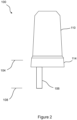
- Figure 2 shows a second example of the apparatus 100.
- the housing 110 comprises a skirt portion 114 that is configured to extend from the bottom of the housing 110.
- the first sensor 102 is substantially located within a recess defined by the skirt portion 114. As the fluid level rises from normal conditions to abnormal conditions, then the presence of the skirt portion 114 reduces the risk that the first sensor 102 will be submerged in the fluid and so will not require cleaning.
- the second sensor 106 may protrude below the extent of the skirt portion 114 such that the second threshold 108 is below the bottom of the skirt portion 114.
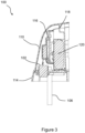
- Figure 3 shows a cross sectional view through the apparatus 100.
- the housing 110 may be substantially hollow to define a cavity in which electronic components are located.
- the apparatus 100 includes one or more of a PCB well assembly 116, a cable entry point 118 and power source 120, such as a battery.
- the battery has an expected operating life of 5 years, in another example, the battery has an expected operating life of 10 years.
- the apparatus 100 in the example shown in Figure 3 includes a connector 122 for an external antenna (not shown).
- the apparatus 100 comprises a data logger for recording the data obtained by the first sensor 102 and the second sensor 106.
- the first sensor 102 and the second sensor 106 may be configured to output data indicative of the fluid level on a single data line. The obviates the requirement for there to be multiple data lines for each of the sensors.
- the apparatus 100 includes a processor for processing the obtained data to determine the fluid level in situ.
- the apparatus 100 may also comprise a transmitter for transmitting the obtained data to an external receiver and processing of the data may occur at the external receiver.
- the processor uses artificially intelligent decision-making systems which use learning algorithms to monitor and analyse fluid level data. It has become increasingly important to measure and deliver accurate, high quality, high resolution Level data during normal operating conditions - to enable the machine-learning processes to develop their understanding of normality. It also continues to be critically important to deliver high quality, reliable Depth data during exceptional operating conditions - for example, during high-levels caused by wet weather or blockages.
- the apparatus 100 complies with the ATEX/IECEx Zone 0 Certification (DSEAR) and is configured to operate with any appropriately certified datalogger or telemetry outstation which can deliver its modest power requirements.
- the apparatus 100 may be configured to communicate with the datalogger using a number of serial data transfer protocols including Modbus.
- the apparatus 100 includes a built-in Datalogger and transmitter, such as a NB-IoT modem (2G fall-back option) with a high-performance internal antenna. For marginal conditions where signal strength is really poor, there may be a connector for an optional external antenna.
- the apparatus complies with ATEX/IECEx Zone 0 Certification and is configured to fit into the "Manhole at the bottom of the garden".
- the apparatus 100 has a range of simple mounting options suited to both flat-walled, (brick-built) chambers and the more modern 350mm and 600mm diameter prefabricated plastic chambers. It is ideal for shallow (350mm minimum depth) manhole applications, can be configured for further cost-saving by using one or other of the Level or Depth sensors (rather than both).
- the apparatus 100 is particularly suited for use in a sewer network for monitoring the sewage level.
- the apparatus 100 may be used in wastewater sewer network monitoring applications.
- the apparatus 100 enables better operational management and pollution prevention objectives.
- the apparatus 100 may also be used for monitoring domestic sewer manholes for blockages to help prevent internal sewer-flooding and localised pollution.
- the apparatus 100 may be used for river and other channel water course depth observation/environmental monitoring and early-warning flood prevention applications.
- the apparatus 100 may be used in storm-water drainage network to monitor storm water levels.
- Figure 4 shows a view from the underside of the apparatus 100.
- the apparatus 100 may include a plate 124 that is located towards the bottom of the apparatus 100.
- a skirt extends beyond the plate 124.
- the first sensor 102 and the second sensor 106 may be coupled with the plate 124.
- the apparatus 100 in the example shown in Figure 4 includes a connector 122 for an external antenna (not shown).
- Figures 5A to 5D show various views of the apparatus.
- Figure 5A shows a front elevation of the apparatus 100.
- the apparatus 100 includes a mount 126, such as a bracket for mounting the apparatus 100 to a wall of a chamber.
- the mounting 126 may be used to mount the apparatus to flat-walled brick-built chambers.
- the mounting 126 may also be used to mount the apparatus 100 to more modern circular chambers, for example chambers having a diameter of between 350mm and 600mm.
- the apparatus is ideal for use with shallow (350mm minimum depth) manhole applications,
- Figures 5B to 5D show various perspective views of the apparatus 100.
- Figure 6 shows an example of the steps for measuring a fluid level in an open-channel system.
- data indicative of the fluid level below a second threshold level 108, which is lower than a first threshold level is obtaining at a first sensor 102.
- data indicative of fluid level between the first threshold level 104 and the second threshold level 108 is obtained at both the first sensor 102 and a second sensor 106.
- data indicative of fluid level above the first threshold level 104 is obtained at the second sensor 106.
- the method may also include the step of calibrating the data indicative of the fluid level obtained by the second sensor 106 based on the data obtained by the first sensor 102 indicative of the fluid level.
- a computer-readable storage medium comprising instructions, which when executed by a computer, cause the computer to carry out the method of measuring a fluid level in an open-channel system identified above.
- a computer program product comprising instructions, which when the program is executed by a computer, cause the computer to carry out the method of measuring a fluid level in an open-channel system identified above.
Landscapes
- Physics & Mathematics (AREA)
- Fluid Mechanics (AREA)
- General Physics & Mathematics (AREA)
- Acoustics & Sound (AREA)
- Electromagnetism (AREA)
- Thermal Sciences (AREA)
- Measurement Of Levels Of Liquids Or Fluent Solid Materials (AREA)
- Indicating Or Recording The Presence, Absence, Or Direction Of Movement (AREA)
Priority Applications (3)
| Application Number | Priority Date | Filing Date | Title |
|---|---|---|---|
| RS20250602A RS66926B1 (sr) | 2020-01-23 | 2021-01-18 | Aparat za praćenje protoka u otvorenom kanalu |
| SM20250231T SMT202500231T1 (it) | 2020-01-23 | 2021-01-18 | Apparato di monitoraggio di flusso a canale aperto |
| HRP20250720TT HRP20250720T1 (hr) | 2020-01-23 | 2021-01-18 | Uređaj za nadzor protoka u otvorenom kanalu |
Applications Claiming Priority (2)
| Application Number | Priority Date | Filing Date | Title |
|---|---|---|---|
| GB2000998.1A GB2591274B (en) | 2020-01-23 | 2020-01-23 | Open channel flow monitoring apparatus |
| PCT/GB2021/050106 WO2021148778A1 (en) | 2020-01-23 | 2021-01-18 | Open channel flow monitoring apparatus |
Publications (3)
| Publication Number | Publication Date |
|---|---|
| EP4094053A1 EP4094053A1 (en) | 2022-11-30 |
| EP4094053C0 EP4094053C0 (en) | 2025-04-30 |
| EP4094053B1 true EP4094053B1 (en) | 2025-04-30 |
Family
ID=69725955
Family Applications (1)
| Application Number | Title | Priority Date | Filing Date |
|---|---|---|---|
| EP21700809.3A Active EP4094053B1 (en) | 2020-01-23 | 2021-01-18 | Open channel flow monitoring apparatus |
Country Status (13)
| Country | Link |
|---|---|
| US (1) | US12422299B2 (pl) |
| EP (1) | EP4094053B1 (pl) |
| AU (1) | AU2021211183B2 (pl) |
| CA (1) | CA3163309A1 (pl) |
| ES (1) | ES3034194T3 (pl) |
| GB (1) | GB2591274B (pl) |
| HR (1) | HRP20250720T1 (pl) |
| HU (1) | HUE071578T2 (pl) |
| PL (1) | PL4094053T3 (pl) |
| RS (1) | RS66926B1 (pl) |
| SM (1) | SMT202500231T1 (pl) |
| WO (1) | WO2021148778A1 (pl) |
| ZA (1) | ZA202207054B (pl) |
Families Citing this family (2)
| Publication number | Priority date | Publication date | Assignee | Title |
|---|---|---|---|---|
| WO2001020865A1 (en) | 1999-09-15 | 2001-03-22 | Aware, Inc. | Multicarrier system with dynamic switching between active application sets |
| NL2036238B1 (en) * | 2023-11-10 | 2025-05-20 | Ireckon Water B V | Ultrasonic monitoring of filling levels in drainage elements |
Family Cites Families (18)
| Publication number | Priority date | Publication date | Assignee | Title |
|---|---|---|---|---|
| US5633809A (en) | 1989-12-22 | 1997-05-27 | American Sigma, Inc. | Multi-function flow monitoring apparatus with area velocity sensor capability |
| US5184510A (en) * | 1991-12-23 | 1993-02-09 | Ford Motor Company | Liquid level sensor |
| JP3201140B2 (ja) | 1994-05-31 | 2001-08-20 | ソニー株式会社 | 電子機器装置 |
| GB2334782B (en) | 1998-02-25 | 2002-02-13 | Federal Ind Ind Group Inc | Acoustic transducers |
| DE10119471A1 (de) * | 2001-04-20 | 2002-10-31 | Micronas Gmbh | Verfahren und Zweidrahtsensor zur Messung einer physikalischen Größe |
| US6986389B2 (en) * | 2003-05-02 | 2006-01-17 | Weatherford/Lamb, Inc. | Adjustable deployment apparatus for an actively clamped tubing-conveyed in-well seismic station |
| FR2922625B1 (fr) * | 2007-10-18 | 2009-12-04 | Valcap Valence Capteur | Dispositif et procede de surveillance d'un reseau de conduites de liquides et reseau equipe d'un tel dispositif |
| US8385155B2 (en) * | 2010-03-05 | 2013-02-26 | Exelis Inc. | Digital hydrophone |
| EP2889589A1 (en) * | 2013-12-24 | 2015-07-01 | Honeywell International Inc. | Bulk acoustic wave (BAW) sensors for liquid level measurements |
| CN203949779U (zh) * | 2014-06-19 | 2014-11-19 | 湖南高速铁路职业技术学院 | 铁路轨枕检测数据采集装置 |
| US20160054164A1 (en) * | 2014-08-19 | 2016-02-25 | Honeywell International Inc. | Compensated fluid level transmitter |
| CN104316140A (zh) | 2014-11-12 | 2015-01-28 | 成都蓝宇科维科技有限公司 | 一种水位监测器 |
| CN205301889U (zh) * | 2015-09-06 | 2016-06-08 | 浙江科技学院 | 一种适用于多种接口类型传感器的数模混合接口电路 |
| JP3201140U (ja) * | 2015-09-11 | 2015-11-19 | ペンタフ株式会社 | 平水時洪水時兼用水位計 |
| US11261722B2 (en) * | 2017-09-29 | 2022-03-01 | Bp Corporation North America Inc. | Systems and methods for monitoring components of a well |
| DE202017106083U1 (de) * | 2017-10-06 | 2019-01-17 | Acs-Control-System Gmbh | Pegelmessvorrichtung |
| KR102037873B1 (ko) * | 2018-06-18 | 2019-10-29 | (주)수인테크 | 다중 수위 입력방식의 침적식 초음파유량계 |
| CN110530456B (zh) * | 2019-10-10 | 2025-06-10 | 南京墨行信息技术有限公司 | 一种用于水位测量用压力传感器零漂校准装置 |
-
2020
- 2020-01-23 GB GB2000998.1A patent/GB2591274B/en active Active
-
2021
- 2021-01-18 CA CA3163309A patent/CA3163309A1/en active Pending
- 2021-01-18 EP EP21700809.3A patent/EP4094053B1/en active Active
- 2021-01-18 RS RS20250602A patent/RS66926B1/sr unknown
- 2021-01-18 HR HRP20250720TT patent/HRP20250720T1/hr unknown
- 2021-01-18 AU AU2021211183A patent/AU2021211183B2/en active Active
- 2021-01-18 HU HUE21700809A patent/HUE071578T2/hu unknown
- 2021-01-18 WO PCT/GB2021/050106 patent/WO2021148778A1/en not_active Ceased
- 2021-01-18 US US17/794,689 patent/US12422299B2/en active Active
- 2021-01-18 ES ES21700809T patent/ES3034194T3/es active Active
- 2021-01-18 PL PL21700809.3T patent/PL4094053T3/pl unknown
- 2021-01-18 SM SM20250231T patent/SMT202500231T1/it unknown
-
2022
- 2022-06-24 ZA ZA2022/07054A patent/ZA202207054B/en unknown
Also Published As
| Publication number | Publication date |
|---|---|
| HUE071578T2 (hu) | 2025-09-28 |
| RS66926B1 (sr) | 2025-07-31 |
| CA3163309A1 (en) | 2021-07-29 |
| EP4094053A1 (en) | 2022-11-30 |
| NZ791436A (en) | 2025-02-28 |
| WO2021148778A1 (en) | 2021-07-29 |
| GB202000998D0 (en) | 2020-03-11 |
| US20230044547A1 (en) | 2023-02-09 |
| EP4094053C0 (en) | 2025-04-30 |
| SMT202500231T1 (it) | 2025-07-22 |
| AU2021211183A1 (en) | 2022-09-15 |
| ES3034194T3 (en) | 2025-08-13 |
| HRP20250720T1 (hr) | 2025-08-15 |
| US12422299B2 (en) | 2025-09-23 |
| GB2591274A (en) | 2021-07-28 |
| PL4094053T3 (pl) | 2025-10-13 |
| ZA202207054B (en) | 2024-12-18 |
| GB2591274B (en) | 2022-02-23 |
| AU2021211183B2 (en) | 2023-12-21 |
Similar Documents
| Publication | Publication Date | Title |
|---|---|---|
| EP4094053B1 (en) | Open channel flow monitoring apparatus | |
| US8100006B2 (en) | Liquid level measurement device and installation incorporating the same | |
| EP2545344B1 (en) | Determining a blockage of a waste water conduit | |
| US8215183B2 (en) | Augmented surface sensor for measuring flow velocity | |
| KR101888188B1 (ko) | 누수감지가 가능한 초음파 수도미터기, 이를 구비한 누수 감지시스템 및 이를 이용한 누수위치 감지방법 | |
| US20170234717A1 (en) | Water amount measurement device and water amount monitoring system | |
| KR101452716B1 (ko) | 초음파 센서의 수신 주파수 필터링을 통해 디펜스 기능을 갖는 초음파 수위측정장치 및 수위측정방법 | |
| CN105527456A (zh) | 窨井排水状态监测系统及方法 | |
| CN109084864B (zh) | 一种细长直管型超声波液位测量装置及测量方法 | |
| JP2015129709A (ja) | 水位センサ、水位検知システム、水分量センサおよび水分量検知システム。 | |
| WO2009037501A1 (en) | Measurement of flow in a channel | |
| KR101608819B1 (ko) | 토양, 지하수오염 예방을 위한 주유소의 누유 검출장치 및 누유 검출시스템 | |
| KR20210012360A (ko) | 오접감지 및 수질/유량측정이 가능한 오수용 맨홀 | |
| CA2598215C (en) | Liquid level measurement device and installation incorporating the same | |
| KR101845238B1 (ko) | 복합 센싱 구조의 유량검출 장치 | |
| CN213984978U (zh) | 一种导波式雷达管井沉积物厚度检测装置 | |
| US20220326107A1 (en) | Method for locating a leak in a water supply network | |
| CN212363318U (zh) | 基于物联网的排水管道监测装置 | |
| NZ791436B2 (en) | Open channel flow monitoring apparatus | |
| JP2019066358A (ja) | 水位計測装置 | |
| JP3752340B2 (ja) | 超音波ドップラー流速・流量計 | |
| JP3244175B2 (ja) | 流量測定装置 | |
| CN219977525U (zh) | 一种城市内涝与排水监测雷达式液位装置 | |
| JP2000009508A (ja) | 超音波ドップラー流速計 | |
| CN216431276U (zh) | 管道监测装置和系统 |
Legal Events
| Date | Code | Title | Description |
|---|---|---|---|
| REG | Reference to a national code |
Ref country code: HR Ref legal event code: TUEP Ref document number: P20250720T Country of ref document: HR |
|
| STAA | Information on the status of an ep patent application or granted ep patent |
Free format text: STATUS: UNKNOWN |
|
| STAA | Information on the status of an ep patent application or granted ep patent |
Free format text: STATUS: THE INTERNATIONAL PUBLICATION HAS BEEN MADE |
|
| PUAI | Public reference made under article 153(3) epc to a published international application that has entered the european phase |
Free format text: ORIGINAL CODE: 0009012 |
|
| STAA | Information on the status of an ep patent application or granted ep patent |
Free format text: STATUS: REQUEST FOR EXAMINATION WAS MADE |
|
| 17P | Request for examination filed |
Effective date: 20220715 |
|
| AK | Designated contracting states |
Kind code of ref document: A1 Designated state(s): AL AT BE BG CH CY CZ DE DK EE ES FI FR GB GR HR HU IE IS IT LI LT LU LV MC MK MT NL NO PL PT RO RS SE SI SK SM TR |
|
| DAV | Request for validation of the european patent (deleted) | ||
| DAX | Request for extension of the european patent (deleted) | ||
| REG | Reference to a national code |
Ref country code: DE Ref legal event code: R079 Ref document number: 602021029966 Country of ref document: DE Free format text: PREVIOUS MAIN CLASS: G01F0023140000 Ipc: G01F0025000000 |
|
| GRAP | Despatch of communication of intention to grant a patent |
Free format text: ORIGINAL CODE: EPIDOSNIGR1 |
|
| STAA | Information on the status of an ep patent application or granted ep patent |
Free format text: STATUS: GRANT OF PATENT IS INTENDED |
|
| RIC1 | Information provided on ipc code assigned before grant |
Ipc: G01F 25/20 20220101ALI20240703BHEP Ipc: G01F 23/14 20060101ALI20240703BHEP Ipc: G01F 23/296 20220101ALI20240703BHEP Ipc: G01F 25/00 20220101AFI20240703BHEP |
|
| INTG | Intention to grant announced |
Effective date: 20240724 |
|
| GRAJ | Information related to disapproval of communication of intention to grant by the applicant or resumption of examination proceedings by the epo deleted |
Free format text: ORIGINAL CODE: EPIDOSDIGR1 |
|
| STAA | Information on the status of an ep patent application or granted ep patent |
Free format text: STATUS: REQUEST FOR EXAMINATION WAS MADE |
|
| GRAP | Despatch of communication of intention to grant a patent |
Free format text: ORIGINAL CODE: EPIDOSNIGR1 |
|
| STAA | Information on the status of an ep patent application or granted ep patent |
Free format text: STATUS: GRANT OF PATENT IS INTENDED |
|
| INTC | Intention to grant announced (deleted) | ||
| INTG | Intention to grant announced |
Effective date: 20241219 |
|
| GRAS | Grant fee paid |
Free format text: ORIGINAL CODE: EPIDOSNIGR3 |
|
| RAP3 | Party data changed (applicant data changed or rights of an application transferred) |
Owner name: DETECTRONIC LIMITED |
|
| GRAA | (expected) grant |
Free format text: ORIGINAL CODE: 0009210 |
|
| STAA | Information on the status of an ep patent application or granted ep patent |
Free format text: STATUS: THE PATENT HAS BEEN GRANTED |
|
| AK | Designated contracting states |
Kind code of ref document: B1 Designated state(s): AL AT BE BG CH CY CZ DE DK EE ES FI FR GB GR HR HU IE IS IT LI LT LU LV MC MK MT NL NO PL PT RO RS SE SI SK SM TR |
|
| REG | Reference to a national code |
Ref country code: CH Ref legal event code: EP Ref country code: GB Ref legal event code: FG4D |
|
| REG | Reference to a national code |
Ref country code: IE Ref legal event code: FG4D |
|
| REG | Reference to a national code |
Ref country code: DE Ref legal event code: R096 Ref document number: 602021029966 Country of ref document: DE |
|
| RAP4 | Party data changed (patent owner data changed or rights of a patent transferred) |
Owner name: DETECTRONIC LIMITED |
|
| U01 | Request for unitary effect filed |
Effective date: 20250529 |
|
| U07 | Unitary effect registered |
Designated state(s): AT BE BG DE DK EE FI FR IT LT LU LV MT NL PT RO SE SI Effective date: 20250611 |
|
| REG | Reference to a national code |
Ref country code: ES Ref legal event code: FG2A Ref document number: 3034194 Country of ref document: ES Kind code of ref document: T3 Effective date: 20250813 Ref country code: SK Ref legal event code: T3 Ref document number: E 46582 Country of ref document: SK |
|
| REG | Reference to a national code |
Ref country code: HR Ref legal event code: T1PR Ref document number: P20250720 Country of ref document: HR |
|
| REG | Reference to a national code |
Ref country code: GR Ref legal event code: EP Ref document number: 20250401223 Country of ref document: GR Effective date: 20250707 |
|
| REG | Reference to a national code |
Ref country code: HU Ref legal event code: AG4A Ref document number: E071578 Country of ref document: HU |