EP4093595B1 - Finish of a preform and a container formed from the preform - Google Patents
Finish of a preform and a container formed from the preform Download PDFInfo
- Publication number
- EP4093595B1 EP4093595B1 EP20920442.9A EP20920442A EP4093595B1 EP 4093595 B1 EP4093595 B1 EP 4093595B1 EP 20920442 A EP20920442 A EP 20920442A EP 4093595 B1 EP4093595 B1 EP 4093595B1
- Authority
- EP
- European Patent Office
- Prior art keywords
- finish
- preform
- undersurface
- brim
- support flange
- Prior art date
- Legal status (The legal status is an assumption and is not a legal conclusion. Google has not performed a legal analysis and makes no representation as to the accuracy of the status listed.)
- Active
Links
Images


Classifications
-
- B—PERFORMING OPERATIONS; TRANSPORTING
- B29—WORKING OF PLASTICS; WORKING OF SUBSTANCES IN A PLASTIC STATE IN GENERAL
- B29C—SHAPING OR JOINING OF PLASTICS; SHAPING OF MATERIAL IN A PLASTIC STATE, NOT OTHERWISE PROVIDED FOR; AFTER-TREATMENT OF THE SHAPED PRODUCTS, e.g. REPAIRING
- B29C49/00—Blow-moulding, i.e. blowing a preform or parison to a desired shape within a mould; Apparatus therefor
- B29C49/071—Preforms or parisons characterised by their configuration, e.g. geometry, dimensions or physical properties
-
- B—PERFORMING OPERATIONS; TRANSPORTING
- B29—WORKING OF PLASTICS; WORKING OF SUBSTANCES IN A PLASTIC STATE IN GENERAL
- B29B—PREPARATION OR PRETREATMENT OF THE MATERIAL TO BE SHAPED; MAKING GRANULES OR PREFORMS; RECOVERY OF PLASTICS OR OTHER CONSTITUENTS OF WASTE MATERIAL CONTAINING PLASTICS
- B29B11/00—Making preforms
- B29B11/14—Making preforms characterised by structure or composition
-
- B—PERFORMING OPERATIONS; TRANSPORTING
- B29—WORKING OF PLASTICS; WORKING OF SUBSTANCES IN A PLASTIC STATE IN GENERAL
- B29C—SHAPING OR JOINING OF PLASTICS; SHAPING OF MATERIAL IN A PLASTIC STATE, NOT OTHERWISE PROVIDED FOR; AFTER-TREATMENT OF THE SHAPED PRODUCTS, e.g. REPAIRING
- B29C49/00—Blow-moulding, i.e. blowing a preform or parison to a desired shape within a mould; Apparatus therefor
- B29C49/02—Combined blow-moulding and manufacture of the preform or the parison
- B29C2049/024—Combined blow-moulding and manufacture of the preform or the parison not using inherent heat of the preform, i.e. 2 step blow moulding
-
- B—PERFORMING OPERATIONS; TRANSPORTING
- B29—WORKING OF PLASTICS; WORKING OF SUBSTANCES IN A PLASTIC STATE IN GENERAL
- B29C—SHAPING OR JOINING OF PLASTICS; SHAPING OF MATERIAL IN A PLASTIC STATE, NOT OTHERWISE PROVIDED FOR; AFTER-TREATMENT OF THE SHAPED PRODUCTS, e.g. REPAIRING
- B29C2949/00—Indexing scheme relating to blow-moulding
- B29C2949/07—Preforms or parisons characterised by their configuration
- B29C2949/0715—Preforms or parisons characterised by their configuration the preform having one end closed
-
- B—PERFORMING OPERATIONS; TRANSPORTING
- B29—WORKING OF PLASTICS; WORKING OF SUBSTANCES IN A PLASTIC STATE IN GENERAL
- B29C—SHAPING OR JOINING OF PLASTICS; SHAPING OF MATERIAL IN A PLASTIC STATE, NOT OTHERWISE PROVIDED FOR; AFTER-TREATMENT OF THE SHAPED PRODUCTS, e.g. REPAIRING
- B29C2949/00—Indexing scheme relating to blow-moulding
- B29C2949/07—Preforms or parisons characterised by their configuration
- B29C2949/076—Preforms or parisons characterised by their configuration characterised by the shape
- B29C2949/0768—Preforms or parisons characterised by their configuration characterised by the shape characterised by the shape of specific parts of preform
- B29C2949/0769—Preforms or parisons characterised by their configuration characterised by the shape characterised by the shape of specific parts of preform characterised by the lip, i.e. very top of preform neck
-
- B—PERFORMING OPERATIONS; TRANSPORTING
- B29—WORKING OF PLASTICS; WORKING OF SUBSTANCES IN A PLASTIC STATE IN GENERAL
- B29C—SHAPING OR JOINING OF PLASTICS; SHAPING OF MATERIAL IN A PLASTIC STATE, NOT OTHERWISE PROVIDED FOR; AFTER-TREATMENT OF THE SHAPED PRODUCTS, e.g. REPAIRING
- B29C2949/00—Indexing scheme relating to blow-moulding
- B29C2949/07—Preforms or parisons characterised by their configuration
- B29C2949/076—Preforms or parisons characterised by their configuration characterised by the shape
- B29C2949/0768—Preforms or parisons characterised by their configuration characterised by the shape characterised by the shape of specific parts of preform
- B29C2949/077—Preforms or parisons characterised by their configuration characterised by the shape characterised by the shape of specific parts of preform characterised by the neck
- B29C2949/0771—Wide-mouth
-
- B—PERFORMING OPERATIONS; TRANSPORTING
- B29—WORKING OF PLASTICS; WORKING OF SUBSTANCES IN A PLASTIC STATE IN GENERAL
- B29C—SHAPING OR JOINING OF PLASTICS; SHAPING OF MATERIAL IN A PLASTIC STATE, NOT OTHERWISE PROVIDED FOR; AFTER-TREATMENT OF THE SHAPED PRODUCTS, e.g. REPAIRING
- B29C2949/00—Indexing scheme relating to blow-moulding
- B29C2949/07—Preforms or parisons characterised by their configuration
- B29C2949/076—Preforms or parisons characterised by their configuration characterised by the shape
- B29C2949/0768—Preforms or parisons characterised by their configuration characterised by the shape characterised by the shape of specific parts of preform
- B29C2949/0778—Preforms or parisons characterised by their configuration characterised by the shape characterised by the shape of specific parts of preform characterised by the flange
-
- B—PERFORMING OPERATIONS; TRANSPORTING
- B29—WORKING OF PLASTICS; WORKING OF SUBSTANCES IN A PLASTIC STATE IN GENERAL
- B29C—SHAPING OR JOINING OF PLASTICS; SHAPING OF MATERIAL IN A PLASTIC STATE, NOT OTHERWISE PROVIDED FOR; AFTER-TREATMENT OF THE SHAPED PRODUCTS, e.g. REPAIRING
- B29C2949/00—Indexing scheme relating to blow-moulding
- B29C2949/07—Preforms or parisons characterised by their configuration
- B29C2949/081—Specified dimensions, e.g. values or ranges
- B29C2949/082—Diameter
- B29C2949/0821—Diameter of the lip, i.e. the very top of the preform neck
-
- B—PERFORMING OPERATIONS; TRANSPORTING
- B29—WORKING OF PLASTICS; WORKING OF SUBSTANCES IN A PLASTIC STATE IN GENERAL
- B29C—SHAPING OR JOINING OF PLASTICS; SHAPING OF MATERIAL IN A PLASTIC STATE, NOT OTHERWISE PROVIDED FOR; AFTER-TREATMENT OF THE SHAPED PRODUCTS, e.g. REPAIRING
- B29C2949/00—Indexing scheme relating to blow-moulding
- B29C2949/07—Preforms or parisons characterised by their configuration
- B29C2949/081—Specified dimensions, e.g. values or ranges
- B29C2949/082—Diameter
- B29C2949/0822—Diameter of the neck
-
- B—PERFORMING OPERATIONS; TRANSPORTING
- B29—WORKING OF PLASTICS; WORKING OF SUBSTANCES IN A PLASTIC STATE IN GENERAL
- B29C—SHAPING OR JOINING OF PLASTICS; SHAPING OF MATERIAL IN A PLASTIC STATE, NOT OTHERWISE PROVIDED FOR; AFTER-TREATMENT OF THE SHAPED PRODUCTS, e.g. REPAIRING
- B29C2949/00—Indexing scheme relating to blow-moulding
- B29C2949/07—Preforms or parisons characterised by their configuration
- B29C2949/081—Specified dimensions, e.g. values or ranges
- B29C2949/082—Diameter
- B29C2949/0825—Diameter of the flange
-
- B—PERFORMING OPERATIONS; TRANSPORTING
- B29—WORKING OF PLASTICS; WORKING OF SUBSTANCES IN A PLASTIC STATE IN GENERAL
- B29C—SHAPING OR JOINING OF PLASTICS; SHAPING OF MATERIAL IN A PLASTIC STATE, NOT OTHERWISE PROVIDED FOR; AFTER-TREATMENT OF THE SHAPED PRODUCTS, e.g. REPAIRING
- B29C2949/00—Indexing scheme relating to blow-moulding
- B29C2949/07—Preforms or parisons characterised by their configuration
- B29C2949/081—Specified dimensions, e.g. values or ranges
- B29C2949/082—Diameter
- B29C2949/0826—Diameter of the body
-
- B—PERFORMING OPERATIONS; TRANSPORTING
- B29—WORKING OF PLASTICS; WORKING OF SUBSTANCES IN A PLASTIC STATE IN GENERAL
- B29C—SHAPING OR JOINING OF PLASTICS; SHAPING OF MATERIAL IN A PLASTIC STATE, NOT OTHERWISE PROVIDED FOR; AFTER-TREATMENT OF THE SHAPED PRODUCTS, e.g. REPAIRING
- B29C49/00—Blow-moulding, i.e. blowing a preform or parison to a desired shape within a mould; Apparatus therefor
- B29C49/02—Combined blow-moulding and manufacture of the preform or the parison
- B29C49/06—Injection blow-moulding
-
- B—PERFORMING OPERATIONS; TRANSPORTING
- B29—WORKING OF PLASTICS; WORKING OF SUBSTANCES IN A PLASTIC STATE IN GENERAL
- B29K—INDEXING SCHEME ASSOCIATED WITH SUBCLASSES B29B, B29C OR B29D, RELATING TO MOULDING MATERIALS OR TO MATERIALS FOR MOULDS, REINFORCEMENTS, FILLERS OR PREFORMED PARTS, e.g. INSERTS
- B29K2623/00—Use of polyalkenes or derivatives thereof for preformed parts, e.g. for inserts
- B29K2623/04—Polymers of ethylene
- B29K2623/06—PE, i.e. polyethylene
- B29K2623/0608—PE, i.e. polyethylene characterised by its density
- B29K2623/065—HDPE, i.e. high density polyethylene
-
- B—PERFORMING OPERATIONS; TRANSPORTING
- B29—WORKING OF PLASTICS; WORKING OF SUBSTANCES IN A PLASTIC STATE IN GENERAL
- B29L—INDEXING SCHEME ASSOCIATED WITH SUBCLASS B29C, RELATING TO PARTICULAR ARTICLES
- B29L2031/00—Other particular articles
- B29L2031/712—Containers; Packaging elements or accessories, Packages
- B29L2031/7158—Bottles
-
- B—PERFORMING OPERATIONS; TRANSPORTING
- B29—WORKING OF PLASTICS; WORKING OF SUBSTANCES IN A PLASTIC STATE IN GENERAL
- B29L—INDEXING SCHEME ASSOCIATED WITH SUBCLASS B29C, RELATING TO PARTICULAR ARTICLES
- B29L2031/00—Other particular articles
- B29L2031/712—Containers; Packaging elements or accessories, Packages
- B29L2031/7158—Bottles
- B29L2031/716—Bottles of the wide mouth type, i.e. the diameters of the bottle opening and its body are substantially identical
Definitions
- the present disclosure relates to a finish of a preform and a container formed from the preform.
- Polymeric containers are used to store various types of liquid food and beverages. Such containers are typically formed from a preform using various processes. One such process involves simultaneously forming the container from a preform and filling the container with any suitable product. This process is commonly referred to as Liquiform ® . To simultaneously form and fill the container, a forming/filling head is placed into cooperation with a finish of the preform, and the preform is stretched into a mold of the container in response to the liquid product being injected under pressure into the container.
- preforms While existing preforms are suitable for their intended use, issues sometimes arise with preforms having relatively larger finishes, such as 48mm in diameter, and formed of high-density polyethylene (HDPE), which is less rigid than other materials, such as Polyethylene Terephthalate (PET).
- HDPE high-density polyethylene
- PET Polyethylene Terephthalate
- Finishes of a preforms and a containers formed from the preforms are for example disclosed in WO 2014/028998 A1 , JP 4 103224 B2 , US 2005/139569 A1 , US 2006/073293 A1 , EP 2 100 707 A1 , US 2015/191269 A1 , US 2003/136084 A1 .
- WO 2014/028998 A1 discloses: A finish of a preform and a container formed from the preform, the finish comprising: a brim defining an opening of the finish, the brim configured to provide a sealing surface with a forming and filling head for forming the container from the preform and filling the container with a product; and a support flange extending from an outer side surface of the finish, the support flange including an undersurface having an inner portion that is directly opposite to the brim; wherein the inner portion of the undersurface of the support flange is closer to an axial center of the finish than an innermost portion of the outer side surface.
- the minimum outer diameter of the finish outer surface 34' is aligned with the maximum outer diameter of the body 14' where the body 14' is adjacent to the finish 12'.
- the present disclosure thus advantageously eliminates, or greatly reduces, the possibility of the failure condition illustrated in prior art FIG. 4 by configuring the support flange 50 as described above.
- first, second, third, etc. may be used herein to describe various elements, components, regions, layers and/or sections, these elements, components, regions, layers and/or sections should not be limited by these terms. These terms may be only used to distinguish one element, component, region, layer or section from another region, layer or section. Terms such as “first,” “second,” and other numerical terms when used herein do not imply a sequence or order unless clearly indicated by the context. Thus, a first element, component, region, layer or section discussed below could be termed a second element, component, region, layer or section without departing from the teachings of the example embodiments.
Landscapes
- Engineering & Computer Science (AREA)
- Mechanical Engineering (AREA)
- Manufacturing & Machinery (AREA)
- Physics & Mathematics (AREA)
- Geometry (AREA)
- Blow-Moulding Or Thermoforming Of Plastics Or The Like (AREA)
- Moulds For Moulding Plastics Or The Like (AREA)
- Processing And Handling Of Plastics And Other Materials For Molding In General (AREA)
Description
- The present disclosure relates to a finish of a preform and a container formed from the preform.
- This section provides background information related to the present disclosure, which is not necessarily prior art.
- Polymeric containers are used to store various types of liquid food and beverages. Such containers are typically formed from a preform using various processes. One such process involves simultaneously forming the container from a preform and filling the container with any suitable product. This process is commonly referred to as Liquiform®. To simultaneously form and fill the container, a forming/filling head is placed into cooperation with a finish of the preform, and the preform is stretched into a mold of the container in response to the liquid product being injected under pressure into the container.
- While existing preforms are suitable for their intended use, issues sometimes arise with preforms having relatively larger finishes, such as 48mm in diameter, and formed of high-density polyethylene (HDPE), which is less rigid than other materials, such as Polyethylene Terephthalate (PET).
- Finishes of a preforms and a containers formed from the preforms are for example disclosed in
WO 2014/028998 A1 ,JP 4 103224 B2 US 2005/139569 A1 ,US 2006/073293 A1 ,EP 2 100 707 A1 ,US 2015/191269 A1 ,US 2003/136084 A1 .WO 2014/028998 A1 discloses:
A finish of a preform and a container formed from the preform, the finish comprising: a brim defining an opening of the finish, the brim configured to provide a sealing surface with a forming and filling head for forming the container from the preform and filling the container with a product; and a support flange extending from an outer side surface of the finish, the support flange including an undersurface having an inner portion that is directly opposite to the brim; wherein the inner portion of the undersurface of the support flange is closer to an axial center of the finish than an innermost portion of the outer side surface. - With such finishes, a support flange thereof has been observed to deflect into the mold that the preform is stretched and blown into. Deflection of the support flange results in leakage between a sealing surface at a brim of the preform and the forming/filling head during forming and filling. The inability to establish a consistent and lasting seal between the sealing surface at the brim of the finish and the forming/filling head may result in an inability to hold pressure on the container during forming and decreased "definition" in the container post-forming. The present disclosure advantageously includes an improved finish of a preform and a container formed from the preform that overcomes the issues described above, and provides numerous additional advantages and unexpected results as explained herein and as one skilled in the art will appreciate.
- This section provides a general summary of the disclosure, and is not a comprehensive disclosure of its full scope or all of its features. The invention relates to a finish and the invention is defined by the features of claim 1.
- The present disclosure includes a finish of a preform and a container formed from the preform. The finish has a brim defining an opening of the finish. The brim is configured to provide a sealing surface with a forming and filling head for forming the container from the preform and filling the container with a product. A support flange extends from an outer side surface of the finish. The support flange includes an undersurface having an inner portion that is directly opposite to the brim.
- The present disclosure also includes a finish of a preform and a container formed from the preform. The finish has a brim defining an opening of the finish. The brim is configured to provide a sealing surface with a forming and filling head for forming the container from the preform and filling the container with a product. A support flange extends from an outer side surface of the preform. The support flange includes an undersurface and an upper surface opposite to the under surface. The undersurface has a larger radial area than the upper surface.
- Further areas of applicability will become apparent from the description provided herein. The description and specific examples in this summary are intended for purposes of illustration only and are not intended to limit the scope of the present disclosure.
- The drawings described herein are for illustrative purposes only of selected embodiments and not all possible implementations, and are not intended to limit the scope of the present disclosure.
-
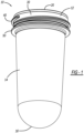
FIG. 1 is a perspective view of a preform in accordance with the present disclosure from which a container can be formed; -
FIG. 2 is a cross-sectional view of the preform ofFIG. 1 ; -
FIG. 3 illustrates cooperation between a support flange of the preform ofFIG. 1 and a mold for forming the container from the preform; and -
FIG. 4 is a cross-sectional view of interaction between a support flange of a prior art preform and a mold for forming a container from the prior art preform. - Corresponding reference numerals indicate corresponding parts throughout the several views of the drawings.
- Example embodiments will now be described more fully with reference to the accompanying drawings.
-
FIG. 1 illustrates apreform 10 in accordance with the present disclosure. Thepreform 10 is configured to be formed into a container for storing any suitable product by way of any suitable forming process. One such process is known as Liquiform®, whereby thepreform 10 is simultaneously stretched into a blow mold 110 (seeFIG. 3 ) and filled with any suitable product. Suitable products include, but are not limited to, water, sports drinks, juices, sauces, any suitable foodstuffs, etc. Thepreform 10 and resulting container may be formed of any suitable polymeric material, such as polyethylene terephthalate, low-density polyethylene, high-density polyethylene, polypropylene, and polystyrene, for example. - The
preform 10 generally includes afinish 12, abody 14, and abase 16. Thefinish 12 remains the same, or substantially the same, throughout the forming and filling process. Thebody 14 is blown into theblow mold 110 to form a body of the container. Thebase 16 forms a base of the container. - The
finish 12 includes abrim 20, which is an annular brim defining anopening 22 of thefinish 12, which is ultimately an opening of the container formed from thepreform 10. At thebrim 20, thefinish 12 may have any suitable diameter, such as 48mm, about 48mm or at least 48mm. Thebrim 20 provides a sealing surface against which any suitable forming and filling head of a Liquiform® forming and filling machine can seal against. With the forming and filling head sealed to thebrim 20, any suitable product can be injected into thepreform 10 at high pressure to expand thebody 14 and thebase 16 into theblow mold 110 to form and fill the container. - The
finish 12 includes anouter surface 30. At theouter surface 30 arethreads 40. Thethreads 40 may extend from theouter surface 30 as illustrated, or be recessed within theouter surface 30. Thethreads 40 are configured to cooperate with any suitable closure for closing theopening 22. - The
finish 12 further includes asupport flange 50. Thesupport flange 50 is configured to support thepreform 10 against theblow mold 110 during the forming and filling process, as illustrated inFIG. 3 . Thesupport flange 50 includes anundersurface 52, which is opposite to anupper surface 54. Theundersurface 52 includes aninner portion 56 and anouter portion 58. Theinner portion 56 is inboard relative to theouter portion 58. Thus relative to an axial center of thefinish 12 and theoverall preform 10, through which a longitudinal axis A extends, theinner portion 56 is closer to the axial center than theouter portion 58. - The
inner portion 56 is directly opposite to thebrim 20, such that theinner surface 56 is linearly and vertically aligned with thebrim 20. Theouter portion 58 is vertically offset from thebrim 20, and is thus outboard of thebrim 20 relative to the axial center of thefinish 12. Thesupport flange 50 is an annular flange with theundersurface 52 having a larger radial area as compared to theupper surface 54. Theundersurface 52 is radially longer than theupper surface 54. -
FIGS. 2 and3 include a linear line B extending parallel to the longitudinal axis A along an innermost portion of theouter surface 30. Line B is also aligned with an outermost portion of thebrim 20. Thus line B extends along a minimum outer diameter of thefinish 12. At a portion of thebody 14 directly adjacent to thefinish 12, thepreform body 14 has a maximum outer diameter that is less than the minimum outer diameter of thefinish 14 along which line B extends. Thus where thebody 14 meets thefinish 12, a maximum outer diameter of thebody 14 is less than a minimum outer diameter of thefinish 12. - As illustrated in
FIG. 3 , when thepreform 10 is seated in theblow mold 110, such that thesupport flange 50 sits on an exterior surface of theblow mold 110, the blow mold 110 (and specifically a striker plate thereof) is aligned with thebrim 20, and is directly opposite to thebrim 20. This configuration reinforces thefinish 12. Thus, when the filling and forming head seals against thebrim 20 and applies force against thebrim 20, thesupport flange 50 will not deform. This is in contrast to prior art preforms, such as the preform 10' ofFIG. 4 , which may experience deformation at the finish 12'. - The prior art preform 10' is illustrated in prior art
FIG. 4 with portions thereof that are similar to thepreform 10 identified inFIG. 4 using the same reference numbers of thepreform 10, but with the prime (') designation. Unlike thesupport flange 50 of thepreform 10, no portion of the prior art support flange 50' is opposite to the brim 20'. The undersurface 52' and upper surface 54' of the support flange 50' have the same radial area and the same radial length. Furthermore, where the body 14' is adjacent to the finish 12', the body 14' has a maximum outer diameter that is the same as a minimum outer diameter of the finish 12'. With respect to line B', which extends parallel to a longitudinal axis of the preform 10', the minimum outer diameter of the finish outer surface 34' is aligned with the maximum outer diameter of the body 14' where the body 14' is adjacent to the finish 12'. Thus the priorart support flange 50 is not reinforced, and is subject to being deformed to position 50" when a forming and filling head applies pressure to thebrim 20. The present disclosure thus advantageously eliminates, or greatly reduces, the possibility of the failure condition illustrated in prior artFIG. 4 by configuring thesupport flange 50 as described above. - Maintaining the
support flange 50 intact advantageously allows for a consistent and lasting seal between thebrim 20 and the forming/filling head, which advantageously results in the ability to hold pressure on thefinish 12 during forming and increased definition in the formed container. One skilled in the art will appreciate that the present disclosure provides numerous additional advantages and unexpected results as well. - The foregoing description of the embodiments has been provided for purposes of illustration and description. It is not intended to be exhaustive or to limit the disclosure. Individual elements or features of a particular embodiment are generally not limited to that particular embodiment, but, where applicable, are interchangeable and can be used in a selected embodiment, even if not specifically shown or described. The same may also be varied in many ways. Such variations are not to be regarded as a departure from the disclosure, and all such modifications are intended to be included within the scope of the disclosure.
- Example embodiments are provided so that this disclosure will be thorough, and will fully convey the scope to those who are skilled in the art. Numerous specific details are set forth such as examples of specific components, devices, and methods, to provide a thorough understanding of embodiments of the present disclosure. It will be apparent to those skilled in the art that specific details need not be employed, that example embodiments may be embodied in many different forms and that neither should be construed to limit the scope of the disclosure. In some example embodiments, well-known processes, well-known device structures, and well-known technologies are not described in detail.
- The terminology used herein is for the purpose of describing particular example embodiments only and is not intended to be limiting. As used herein, the singular forms "a," "an," and "the" may be intended to include the plural forms as well, unless the context clearly indicates otherwise. The terms "comprises," "comprising," "including," and "having," are inclusive and therefore specify the presence of stated features, integers, steps, operations, elements, and/or components, but do not preclude the presence or addition of one or more other features, integers, steps, operations, elements, components, and/or groups thereof. The method steps, processes, and operations described herein are not to be construed as necessarily requiring their performance in the particular order discussed or illustrated, unless specifically identified as an order of performance. It is also to be understood that additional or alternative steps may be employed.
- When an element or layer is referred to as being "on," "engaged to," "connected to," or "coupled to" another element or layer, it may be directly on, engaged, connected or coupled to the other element or layer, or intervening elements or layers may be present. In contrast, when an element is referred to as being "directly on," "directly engaged to," "directly connected to," or "directly coupled to" another element or layer, there may be no intervening elements or layers present. Other words used to describe the relationship between elements should be interpreted in a like fashion (e.g., "between" versus "directly between," "adjacent" versus "directly adjacent," etc.). As used herein, the term "and/or" includes any and all combinations of one or more of the associated listed items.
- Although the terms first, second, third, etc. may be used herein to describe various elements, components, regions, layers and/or sections, these elements, components, regions, layers and/or sections should not be limited by these terms. These terms may be only used to distinguish one element, component, region, layer or section from another region, layer or section. Terms such as "first," "second," and other numerical terms when used herein do not imply a sequence or order unless clearly indicated by the context. Thus, a first element, component, region, layer or section discussed below could be termed a second element, component, region, layer or section without departing from the teachings of the example embodiments.
- Spatially relative terms, such as "inner," "outer," "beneath," "below," "lower," "above," "upper," and the like, may be used herein for ease of description to describe one element or feature's relationship to another element(s) or feature(s) as illustrated in the figures. Spatially relative terms may be intended to encompass different orientations of the device in use or operation in addition to the orientation depicted in the figures. For example, if the device in the figures is turned over, elements described as "below" or "beneath" other elements or features would then be oriented "above" the other elements or features. Thus, the example term "below" can encompass both an orientation of above and below. The device may be otherwise oriented (rotated 90 degrees or at other orientations) and the spatially relative descriptors used herein interpreted accordingly.
Claims (12)
- A finish (12) of a preform (10) and a container formed from the preform (10), the finish (12) comprising:a brim (20) defining an opening (22) of the finish (12), the brim (20) configured to provide a sealing surface with a forming and filling head for forming the container from the preform (10) and filling the container with a product; anda support flange (50) extending from an outer side surface (30) of the finish (12), the support flange (50) including an undersurface (52) having an inner portion (56) that is directly opposite to the brim (20);wherein the inner portion (56) of the undersurface (52) of the support flange (50) is closer to an axial center of the finish (12) than an innermost portion of the outer side surface (30),characterized in that essentially the whole inner portion (56) of the undersurface (52) of the support flange (50) is linearly aligned with essentially the whole sealing surface of the brim (20), and the inner portion (56) of the undersurface (52) of the support flange (50) is inboard of an outer portion (58) of the undersurface (52) of the support flange (50) relative to the axial center of the finish (12); andthe outer portion (58) is outboard of the brim (20) relative to the axial center of the finish (12).
- The finish (12) of Claim 1,
characterized in that
the finish (12) further comprising threads at the outer side surface (30) of the preform (10), the threads configured to cooperate with a closure for closing the opening (22) of the finish (12). - The finish (12) of Claim 1 or 2,
characterized in that
the inner portion (56) of the undersurface (52) of the support flange (50) is vertically inset relative to the innermost portion of the outer side surface (30). - The finish (12) of one of the preceding Claims,
characterized in that
the finish (12) further comprising a preform (10) body extending from the finish (12);
wherein directly adjacent to the finish (12) the preform (10) body has a maximum outer diameter that is less than a minimum outer diameter of the finish (12). - The finish (12) of one of the preceding Claims,
characterized in that
the support flange (50) further includes an upper surface (54) opposite to the undersurface (52), the undersurface (52) is longer radially than the upper surface (54). - The finish (12) of Claim 5,
characterized in that
the upper surface (54) is linearly offset from the brim (20) and outboard of the brim (20) relative to the axial center of the finish (12). - The finish (12) of one of the preceding Claims,
characterized in that
the finish (12) has a diameter of at least 48mm. - The finish (12) of one of the preceding Claims
characterized in that
the support flange (50) including an upper surface (54) opposite to the undersurface (52), the undersurface (52) has a larger radial area than the upper surface (54). - The finish (12) of Claim 8,
characterized in that
the inner portion (56) of the undersurface (52) is opposite to a body of the finish (12). - The finish (12) of Claim 8 or 9,
characterized in that
the finish (12) further comprising a preform (10) body extending from the finish (12);
wherein directly adjacent to the finish (12) the preform (10) body has a maximum outer diameter that is less than a minimum outer diameter of the finish (12). - The finish (12) of one of Claims 8 to 10,
characterized in that
the finish (12) has a diameter of 48mm. - The finish (12) of one of Claims 1 to 6 and 8 to 11,
characterized in that
the preform (10) and finish (12) are formed of high-density polyethylene (HDPE) and the finish (12) has a diameter of at least 48 mm, wherein preferably the finish (12) has a diameter of 48 mm.
Applications Claiming Priority (1)
| Application Number | Priority Date | Filing Date | Title |
|---|---|---|---|
| PCT/US2020/019137 WO2021167616A1 (en) | 2020-02-21 | 2020-02-21 | Finish of a preform and a container formed from the preform |
Publications (3)
| Publication Number | Publication Date |
|---|---|
| EP4093595A1 EP4093595A1 (en) | 2022-11-30 |
| EP4093595A4 EP4093595A4 (en) | 2024-02-28 |
| EP4093595B1 true EP4093595B1 (en) | 2025-07-02 |
Family
ID=77392219
Family Applications (1)
| Application Number | Title | Priority Date | Filing Date |
|---|---|---|---|
| EP20920442.9A Active EP4093595B1 (en) | 2020-02-21 | 2020-02-21 | Finish of a preform and a container formed from the preform |
Country Status (6)
| Country | Link |
|---|---|
| US (1) | US12466121B2 (en) |
| EP (1) | EP4093595B1 (en) |
| BR (1) | BR112022015957A2 (en) |
| CA (1) | CA3168757A1 (en) |
| MX (1) | MX2022010277A (en) |
| WO (1) | WO2021167616A1 (en) |
Family Cites Families (17)
| Publication number | Priority date | Publication date | Assignee | Title |
|---|---|---|---|---|
| JP4103224B2 (en) * | 1999-01-26 | 2008-06-18 | 東洋製罐株式会社 | Pre-molded body blow-molded into containers |
| US6568156B2 (en) * | 2000-06-30 | 2003-05-27 | Schmalbach-Lubeca Ag | Method of providing a thermally-processed commodity within a plastic container |
| US6536617B2 (en) * | 2001-02-15 | 2003-03-25 | Colgate-Palmolive Company | Bottle with closure holding structure |
| US7097061B2 (en) * | 2003-08-14 | 2006-08-29 | Graham Packaging Pet Technologies Inc. | Plastic container which is hot-fillable and/or having neck finish adapted for receipt of handle |
| US20050139569A1 (en) * | 2003-12-24 | 2005-06-30 | Larsen W. B. | Swage-forming of container or preform internal threads |
| US20050142311A1 (en) * | 2003-12-24 | 2005-06-30 | Nahill Thomas E. | Finish assembly for a plastic container or preform |
| US20060073293A1 (en) * | 2004-10-04 | 2006-04-06 | Nahill Thomas E | Finish assembly, preform assembly, container assembly, and method of manufacture |
| US8308002B2 (en) * | 2006-01-27 | 2012-11-13 | Amcor Limited | Preform and container having thread groove of varying depth |
| US7740792B2 (en) * | 2006-08-03 | 2010-06-22 | Medrad, Inc. | Methods of molding a syringe |
| US8308005B2 (en) | 2008-01-30 | 2012-11-13 | Amcor Limited | Preform and container having debossed support flange |
| US20090223920A1 (en) * | 2008-03-07 | 2009-09-10 | Graham Packaging Company, Lp | Abuse resistant preform and container neck finish |
| EP2100707A1 (en) * | 2008-03-13 | 2009-09-16 | La Seda De Barcelona S.A. | Plastic preform having a low weight sealable neck finish |
| CN104023941B (en) * | 2011-10-27 | 2017-02-01 | 帝斯克玛股份有限公司 | Method and apparatus for forming and filling a container |
| WO2013188560A2 (en) * | 2012-06-12 | 2013-12-19 | Calello Patrick M | Lightweight preform having a decreased weight support ring |
| BR102012021280B1 (en) * | 2012-08-24 | 2022-05-17 | Bernardo Ary Romcy De Sanford Lima | Plastic packaging for carbonated drinks and food, with a large diameter plastic lid, manual opening method, tamper-evident security systems and definitive closing and opening systems |
| CH706889A2 (en) | 2012-09-10 | 2014-03-14 | Alpla Werke | Preform for producing plastic containers in a stretch blow molding. |
| US11247381B2 (en) * | 2013-06-28 | 2022-02-15 | Dai Nippon Printing Co., Ltd. | Composite container, inner label and plastic member |
-
2020
- 2020-02-21 BR BR112022015957A patent/BR112022015957A2/en not_active Application Discontinuation
- 2020-02-21 US US17/800,510 patent/US12466121B2/en active Active
- 2020-02-21 MX MX2022010277A patent/MX2022010277A/en unknown
- 2020-02-21 WO PCT/US2020/019137 patent/WO2021167616A1/en not_active Ceased
- 2020-02-21 CA CA3168757A patent/CA3168757A1/en active Pending
- 2020-02-21 EP EP20920442.9A patent/EP4093595B1/en active Active
Also Published As
| Publication number | Publication date |
|---|---|
| US12466121B2 (en) | 2025-11-11 |
| MX2022010277A (en) | 2022-09-19 |
| BR112022015957A2 (en) | 2022-10-11 |
| US20230087929A1 (en) | 2023-03-23 |
| CA3168757A1 (en) | 2021-08-26 |
| EP4093595A4 (en) | 2024-02-28 |
| WO2021167616A1 (en) | 2021-08-26 |
| EP4093595A1 (en) | 2022-11-30 |
Similar Documents
| Publication | Publication Date | Title |
|---|---|---|
| US10723519B2 (en) | Closure for a package | |
| US7963088B2 (en) | Plastic container base structure and method for hot filling a plastic container | |
| US8651307B2 (en) | Hot-fill container | |
| US10518924B2 (en) | Container base including hemispherical actuating diaphragm | |
| EP3206956B1 (en) | Container with base multi-function | |
| EP3347282B1 (en) | Lightweight polymeric container | |
| CA3079406C (en) | Closure and package that vents at high pressure | |
| EP2259905B1 (en) | Plastic preform having a low weigth heat sealable neck finish | |
| EP3140205B1 (en) | Plastic container with flexible base portion | |
| WO2017195190A1 (en) | Pressurized gas container | |
| MX2015002002A (en) | A cap for containers. | |
| US12466121B2 (en) | Finish of a preform and a container formed from the preform | |
| EP3911576B1 (en) | Vertical displacement container base | |
| US10836561B2 (en) | Aerosol dispenser | |
| US5647495A (en) | Heat-resistant construction of a neck of a synthetic resin container | |
| US20240182215A1 (en) | Closure assembly for filling a container under isolated conditions | |
| AU2004312420A1 (en) | A plastic container or a preform | |
| EP4093596B1 (en) | Container preform and forming/filling nozzle each configured to provide a seal therebetween | |
| US12522416B2 (en) | Container closure with flexible membrane | |
| US10961043B1 (en) | Aerosol container with spaced sealing beads | |
| JPH02122909A (en) | Vessel made of plastic and its manufacture | |
| MXPA06005764A (en) | A preform of a plastic container particularly for packaging foodstuffs |
Legal Events
| Date | Code | Title | Description |
|---|---|---|---|
| STAA | Information on the status of an ep patent application or granted ep patent |
Free format text: STATUS: THE INTERNATIONAL PUBLICATION HAS BEEN MADE |
|
| PUAI | Public reference made under article 153(3) epc to a published international application that has entered the european phase |
Free format text: ORIGINAL CODE: 0009012 |
|
| STAA | Information on the status of an ep patent application or granted ep patent |
Free format text: STATUS: REQUEST FOR EXAMINATION WAS MADE |
|
| 17P | Request for examination filed |
Effective date: 20220823 |
|
| AK | Designated contracting states |
Kind code of ref document: A1 Designated state(s): AL AT BE BG CH CY CZ DE DK EE ES FI FR GB GR HR HU IE IS IT LI LT LU LV MC MK MT NL NO PL PT RO RS SE SI SK SM TR |
|
| DAV | Request for validation of the european patent (deleted) | ||
| DAX | Request for extension of the european patent (deleted) | ||
| REG | Reference to a national code |
Ref country code: DE Ref legal event code: R079 Free format text: PREVIOUS MAIN CLASS: B29C0049000000 Ipc: B29B0011140000 Ref document number: 602020054023 Country of ref document: DE |
|
| A4 | Supplementary search report drawn up and despatched |
Effective date: 20240125 |
|
| RIC1 | Information provided on ipc code assigned before grant |
Ipc: B29L 31/00 20060101ALN20240119BHEP Ipc: B29K 623/00 20060101ALN20240119BHEP Ipc: B29C 49/06 20060101ALN20240119BHEP Ipc: B29B 11/14 20060101AFI20240119BHEP |
|
| REG | Reference to a national code |
Ref country code: DE Ref legal event code: R079 Free format text: PREVIOUS MAIN CLASS: B29B0011140000 Ipc: B29C0049000000 Ref document number: 602020054023 Country of ref document: DE |
|
| GRAP | Despatch of communication of intention to grant a patent |
Free format text: ORIGINAL CODE: EPIDOSNIGR1 |
|
| STAA | Information on the status of an ep patent application or granted ep patent |
Free format text: STATUS: GRANT OF PATENT IS INTENDED |
|
| RIC1 | Information provided on ipc code assigned before grant |
Ipc: B29L 31/00 20060101ALN20250210BHEP Ipc: B29K 623/00 20060101ALN20250210BHEP Ipc: B29C 49/06 20060101ALN20250210BHEP Ipc: B29B 11/14 20060101ALI20250210BHEP Ipc: B29C 49/00 20060101AFI20250210BHEP |
|
| INTG | Intention to grant announced |
Effective date: 20250221 |
|
| GRAS | Grant fee paid |
Free format text: ORIGINAL CODE: EPIDOSNIGR3 |
|
| GRAA | (expected) grant |
Free format text: ORIGINAL CODE: 0009210 |
|
| STAA | Information on the status of an ep patent application or granted ep patent |
Free format text: STATUS: THE PATENT HAS BEEN GRANTED |
|
| AK | Designated contracting states |
Kind code of ref document: B1 Designated state(s): AL AT BE BG CH CY CZ DE DK EE ES FI FR GB GR HR HU IE IS IT LI LT LU LV MC MK MT NL NO PL PT RO RS SE SI SK SM TR |
|
| REG | Reference to a national code |
Ref country code: GB Ref legal event code: FG4D |
|
| REG | Reference to a national code |
Ref country code: CH Ref legal event code: EP |
|
| REG | Reference to a national code |
Ref country code: DE Ref legal event code: R096 Ref document number: 602020054023 Country of ref document: DE |
|
| REG | Reference to a national code |
Ref country code: IE Ref legal event code: FG4D |
|
| P01 | Opt-out of the competence of the unified patent court (upc) registered |
Free format text: CASE NUMBER: UPC_APP_3674_4093595/2025 Effective date: 20250819 |
|
| REG | Reference to a national code |
Ref country code: NL Ref legal event code: MP Effective date: 20250702 |
|
| PG25 | Lapsed in a contracting state [announced via postgrant information from national office to epo] |
Ref country code: PT Free format text: LAPSE BECAUSE OF FAILURE TO SUBMIT A TRANSLATION OF THE DESCRIPTION OR TO PAY THE FEE WITHIN THE PRESCRIBED TIME-LIMIT Effective date: 20251103 |
|
| PG25 | Lapsed in a contracting state [announced via postgrant information from national office to epo] |
Ref country code: NL Free format text: LAPSE BECAUSE OF FAILURE TO SUBMIT A TRANSLATION OF THE DESCRIPTION OR TO PAY THE FEE WITHIN THE PRESCRIBED TIME-LIMIT Effective date: 20250702 |
|
| REG | Reference to a national code |
Ref country code: AT Ref legal event code: MK05 Ref document number: 1808762 Country of ref document: AT Kind code of ref document: T Effective date: 20250702 |
|
| PG25 | Lapsed in a contracting state [announced via postgrant information from national office to epo] |
Ref country code: IS Free format text: LAPSE BECAUSE OF FAILURE TO SUBMIT A TRANSLATION OF THE DESCRIPTION OR TO PAY THE FEE WITHIN THE PRESCRIBED TIME-LIMIT Effective date: 20251102 |
|
| PG25 | Lapsed in a contracting state [announced via postgrant information from national office to epo] |
Ref country code: NO Free format text: LAPSE BECAUSE OF FAILURE TO SUBMIT A TRANSLATION OF THE DESCRIPTION OR TO PAY THE FEE WITHIN THE PRESCRIBED TIME-LIMIT Effective date: 20251002 |
|
| REG | Reference to a national code |
Ref country code: LT Ref legal event code: MG9D |
|
| PG25 | Lapsed in a contracting state [announced via postgrant information from national office to epo] |
Ref country code: AT Free format text: LAPSE BECAUSE OF FAILURE TO SUBMIT A TRANSLATION OF THE DESCRIPTION OR TO PAY THE FEE WITHIN THE PRESCRIBED TIME-LIMIT Effective date: 20250702 |
|
| PG25 | Lapsed in a contracting state [announced via postgrant information from national office to epo] |
Ref country code: FI Free format text: LAPSE BECAUSE OF FAILURE TO SUBMIT A TRANSLATION OF THE DESCRIPTION OR TO PAY THE FEE WITHIN THE PRESCRIBED TIME-LIMIT Effective date: 20250702 |
|
| PG25 | Lapsed in a contracting state [announced via postgrant information from national office to epo] |
Ref country code: HR Free format text: LAPSE BECAUSE OF FAILURE TO SUBMIT A TRANSLATION OF THE DESCRIPTION OR TO PAY THE FEE WITHIN THE PRESCRIBED TIME-LIMIT Effective date: 20250702 |
|
| PGFP | Annual fee paid to national office [announced via postgrant information from national office to epo] |
Ref country code: FR Payment date: 20251222 Year of fee payment: 7 |
|
| PG25 | Lapsed in a contracting state [announced via postgrant information from national office to epo] |
Ref country code: GR Free format text: LAPSE BECAUSE OF FAILURE TO SUBMIT A TRANSLATION OF THE DESCRIPTION OR TO PAY THE FEE WITHIN THE PRESCRIBED TIME-LIMIT Effective date: 20251003 |
|
| PG25 | Lapsed in a contracting state [announced via postgrant information from national office to epo] |
Ref country code: SE Free format text: LAPSE BECAUSE OF FAILURE TO SUBMIT A TRANSLATION OF THE DESCRIPTION OR TO PAY THE FEE WITHIN THE PRESCRIBED TIME-LIMIT Effective date: 20250702 Ref country code: CZ Free format text: LAPSE BECAUSE OF FAILURE TO SUBMIT A TRANSLATION OF THE DESCRIPTION OR TO PAY THE FEE WITHIN THE PRESCRIBED TIME-LIMIT Effective date: 20250702 |
|
| PG25 | Lapsed in a contracting state [announced via postgrant information from national office to epo] |
Ref country code: LV Free format text: LAPSE BECAUSE OF FAILURE TO SUBMIT A TRANSLATION OF THE DESCRIPTION OR TO PAY THE FEE WITHIN THE PRESCRIBED TIME-LIMIT Effective date: 20250702 |
|
| PG25 | Lapsed in a contracting state [announced via postgrant information from national office to epo] |
Ref country code: BG Free format text: LAPSE BECAUSE OF FAILURE TO SUBMIT A TRANSLATION OF THE DESCRIPTION OR TO PAY THE FEE WITHIN THE PRESCRIBED TIME-LIMIT Effective date: 20250702 Ref country code: PL Free format text: LAPSE BECAUSE OF FAILURE TO SUBMIT A TRANSLATION OF THE DESCRIPTION OR TO PAY THE FEE WITHIN THE PRESCRIBED TIME-LIMIT Effective date: 20250702 |
|
| PG25 | Lapsed in a contracting state [announced via postgrant information from national office to epo] |
Ref country code: RS Free format text: LAPSE BECAUSE OF FAILURE TO SUBMIT A TRANSLATION OF THE DESCRIPTION OR TO PAY THE FEE WITHIN THE PRESCRIBED TIME-LIMIT Effective date: 20251002 |
|
| PG25 | Lapsed in a contracting state [announced via postgrant information from national office to epo] |
Ref country code: ES Free format text: LAPSE BECAUSE OF FAILURE TO SUBMIT A TRANSLATION OF THE DESCRIPTION OR TO PAY THE FEE WITHIN THE PRESCRIBED TIME-LIMIT Effective date: 20250702 |
|
| REG | Reference to a national code |
Ref country code: CH Ref legal event code: U11 Free format text: ST27 STATUS EVENT CODE: U-0-0-U10-U11 (AS PROVIDED BY THE NATIONAL OFFICE) Effective date: 20260301 |
|
| PG25 | Lapsed in a contracting state [announced via postgrant information from national office to epo] |
Ref country code: SM Free format text: LAPSE BECAUSE OF FAILURE TO SUBMIT A TRANSLATION OF THE DESCRIPTION OR TO PAY THE FEE WITHIN THE PRESCRIBED TIME-LIMIT Effective date: 20250702 |
|
| PG25 | Lapsed in a contracting state [announced via postgrant information from national office to epo] |
Ref country code: DK Free format text: LAPSE BECAUSE OF FAILURE TO SUBMIT A TRANSLATION OF THE DESCRIPTION OR TO PAY THE FEE WITHIN THE PRESCRIBED TIME-LIMIT Effective date: 20250702 |
|
| PGFP | Annual fee paid to national office [announced via postgrant information from national office to epo] |
Ref country code: DE Payment date: 20251230 Year of fee payment: 7 |
|
| PGFP | Annual fee paid to national office [announced via postgrant information from national office to epo] |
Ref country code: IT Payment date: 20260122 Year of fee payment: 7 |
|
| PGFP | Annual fee paid to national office [announced via postgrant information from national office to epo] |
Ref country code: CH Payment date: 20260301 Year of fee payment: 7 |
|
| PG25 | Lapsed in a contracting state [announced via postgrant information from national office to epo] |
Ref country code: SK Free format text: LAPSE BECAUSE OF FAILURE TO SUBMIT A TRANSLATION OF THE DESCRIPTION OR TO PAY THE FEE WITHIN THE PRESCRIBED TIME-LIMIT Effective date: 20250702 Ref country code: EE Free format text: LAPSE BECAUSE OF FAILURE TO SUBMIT A TRANSLATION OF THE DESCRIPTION OR TO PAY THE FEE WITHIN THE PRESCRIBED TIME-LIMIT Effective date: 20250702 |
|
| PLBE | No opposition filed within time limit |
Free format text: ORIGINAL CODE: 0009261 |
|
| STAA | Information on the status of an ep patent application or granted ep patent |
Free format text: STATUS: NO OPPOSITION FILED WITHIN TIME LIMIT |