EP4093479B1 - Balloon protectors and balloon-catheter assemblies - Google Patents
Balloon protectors and balloon-catheter assemblies Download PDFInfo
- Publication number
- EP4093479B1 EP4093479B1 EP21705375.0A EP21705375A EP4093479B1 EP 4093479 B1 EP4093479 B1 EP 4093479B1 EP 21705375 A EP21705375 A EP 21705375A EP 4093479 B1 EP4093479 B1 EP 4093479B1
- Authority
- EP
- European Patent Office
- Prior art keywords
- balloon
- distal
- catheter
- protector
- piece
- Prior art date
- Legal status (The legal status is an assumption and is not a legal conclusion. Google has not performed a legal analysis and makes no representation as to the accuracy of the status listed.)
- Active
Links
Images


Classifications
-
- A—HUMAN NECESSITIES
- A61—MEDICAL OR VETERINARY SCIENCE; HYGIENE
- A61M—DEVICES FOR INTRODUCING MEDIA INTO, OR ONTO, THE BODY; DEVICES FOR TRANSDUCING BODY MEDIA OR FOR TAKING MEDIA FROM THE BODY; DEVICES FOR PRODUCING OR ENDING SLEEP OR STUPOR
- A61M25/00—Catheters; Hollow probes
- A61M25/10—Balloon catheters
-
- A—HUMAN NECESSITIES
- A61—MEDICAL OR VETERINARY SCIENCE; HYGIENE
- A61M—DEVICES FOR INTRODUCING MEDIA INTO, OR ONTO, THE BODY; DEVICES FOR TRANSDUCING BODY MEDIA OR FOR TAKING MEDIA FROM THE BODY; DEVICES FOR PRODUCING OR ENDING SLEEP OR STUPOR
- A61M25/00—Catheters; Hollow probes
- A61M25/01—Introducing, guiding, advancing, emplacing or holding catheters
- A61M25/06—Body-piercing guide needles or the like
- A61M25/0662—Guide tubes
- A61M25/0668—Guide tubes splittable, tear apart
-
- A—HUMAN NECESSITIES
- A61—MEDICAL OR VETERINARY SCIENCE; HYGIENE
- A61M—DEVICES FOR INTRODUCING MEDIA INTO, OR ONTO, THE BODY; DEVICES FOR TRANSDUCING BODY MEDIA OR FOR TAKING MEDIA FROM THE BODY; DEVICES FOR PRODUCING OR ENDING SLEEP OR STUPOR
- A61M25/00—Catheters; Hollow probes
- A61M25/01—Introducing, guiding, advancing, emplacing or holding catheters
- A61M25/06—Body-piercing guide needles or the like
- A61M25/0662—Guide tubes
- A61M25/0668—Guide tubes splittable, tear apart
- A61M2025/0675—Introducing-sheath slitters
-
- A—HUMAN NECESSITIES
- A61—MEDICAL OR VETERINARY SCIENCE; HYGIENE
- A61M—DEVICES FOR INTRODUCING MEDIA INTO, OR ONTO, THE BODY; DEVICES FOR TRANSDUCING BODY MEDIA OR FOR TAKING MEDIA FROM THE BODY; DEVICES FOR PRODUCING OR ENDING SLEEP OR STUPOR
- A61M25/00—Catheters; Hollow probes
- A61M25/10—Balloon catheters
- A61M2025/1043—Balloon catheters with special features or adapted for special applications
- A61M2025/105—Balloon catheters with special features or adapted for special applications having a balloon suitable for drug delivery, e.g. by using holes for delivery, drug coating or membranes
-
- A—HUMAN NECESSITIES
- A61—MEDICAL OR VETERINARY SCIENCE; HYGIENE
- A61M—DEVICES FOR INTRODUCING MEDIA INTO, OR ONTO, THE BODY; DEVICES FOR TRANSDUCING BODY MEDIA OR FOR TAKING MEDIA FROM THE BODY; DEVICES FOR PRODUCING OR ENDING SLEEP OR STUPOR
- A61M25/00—Catheters; Hollow probes
- A61M25/10—Balloon catheters
- A61M2025/1043—Balloon catheters with special features or adapted for special applications
- A61M2025/1068—Balloon catheters with special features or adapted for special applications having means for varying the length or diameter of the deployed balloon, this variations could be caused by excess pressure
-
- A—HUMAN NECESSITIES
- A61—MEDICAL OR VETERINARY SCIENCE; HYGIENE
- A61M—DEVICES FOR INTRODUCING MEDIA INTO, OR ONTO, THE BODY; DEVICES FOR TRANSDUCING BODY MEDIA OR FOR TAKING MEDIA FROM THE BODY; DEVICES FOR PRODUCING OR ENDING SLEEP OR STUPOR
- A61M25/00—Catheters; Hollow probes
- A61M25/10—Balloon catheters
- A61M2025/1043—Balloon catheters with special features or adapted for special applications
- A61M2025/1081—Balloon catheters with special features or adapted for special applications having sheaths or the like for covering the balloon but not forming a permanent part of the balloon, e.g. retractable, dissolvable or tearable sheaths
Definitions
- Atherosclerosis is characterized by one or more intravascular lesions formed in part of plaque including blood-borne substances such as fat, cholesterol, and calcium.
- An intravascular lesion such as an arterial lesion can form on a wall of an arterial lumen and build out across the lumen to an opposite wall thereof. A last point of patency often occurs at a boundary between the arterial lesion and the opposite wall of the arterial lumen.
- Surgical procedures for atherosclerosis such as balloon angioplasty with drug-coated balloons can be used to restore patency and blood flow lost to the one or more intravascular lesions.
- Balloon protectors are designed to cover and protect the drug-coated balloons of balloon catheters during shipping or preoperative handling, which is needed to maintain integrity of the balloon catheters for the surgical procedures for which they are designed.
- balloon protectors protect clinicians and others from inadvertently coming into contact with anti-proliferative drugs of the drug-coated balloons when handling the balloon catheters before the surgical procedures. While the foregoing needs for balloon protectors continue to exist, additional needs exist such as a need to safeguard against advancing a balloon catheter through an introducer sheath without first removing the balloon protector thereof.
- US 6,110,146 discloses a balloon protector for the balloon of a dilatation catheter including a distally extending flared section that defines a funnel receptive to a guidewire in order to facilitate backloading of the guidewire into the catheter.
- WO2014/179767 discloses a peelable protective sheath for protecting balloon of angioplasty dilatation catheter for treating blockages in arteries of patient, has tab extending axially from body portion and including textured surface on side facing away from axis.
- balloon protectors Disclosed herein are balloon protectors, balloon catheters including the balloon protectors, and methods thereof that meet or exceed the foregoing needs.
- the present invention is directed to the catheter assembly of claim 1.
- the dependent claims refer to preferred embodiments.
- the balloon protector includes a balloon-covering section and a tabbed section proximal of the balloon-covering section.
- the balloon-covering section is configured to cover a drug-coated balloon of the balloon catheter.
- the balloon-covering section includes a tip piece of the balloon protector.
- the tabbed section includes a pair of tabs configured to be continuously pulled away from each other to progressively split the balloon protector along the balloon-covering section until the balloon protector is completely peeled off the balloon.
- the tip piece has a tapered portion having an inner-diameter taper (configured to be) commensurate with an outer diameter of a distal shoulder of the balloon.
- the inner-diameter taper of the tip piece is configured to maintain concentricity between an opening in a distal end of the tip piece and an opening in a distal end of a shaft of the balloon catheter for threading a guidewire therethrough.
- the tip piece has an overlapping portion over the distal-end portion of the body piece.
- the overlapping portion partially overlaps the distal-end portion of the body piece.
- the overlapping portion has an outer diameter greater than that of an immediately proximal portion of the balloon-covering section.
- the outer diameter of the overlapping portion of the tip piece is configured to provide a stop to prevent insertion of the balloon catheter into an introducer sheath while the balloon protector is covering the balloon.
- the tip piece includes a longitudinal gap on each side of two opposing sides of the balloon protector.
- the longitudinal gap has a length greater than or equal to that of the overlapping portion of the tip piece.
- the balloon protector is configured such that the length of the longitudinal gap allows the distal-end portion of the body piece to be split through a distal end of the body piece without an increase in applied peel force.
- the length of the longitudinal gap is greater than that of the overlapping portion of the tip piece. Due to the length of the longitudinal gap, the balloon protector is configured such that a through hole is formed between a distal end of the longitudinal gap and the distal end of the body piece.
- the balloon protector is configured such that the through hole is configured to provide a break in the applied peel force when splitting the balloon protector along the balloon-covering section, the break signaling splitting through the distal end of the body piece.
- both the body piece and the tip piece of the balloon-covering section include a pair of opposing longitudinal lines of weakness aligned with the tabs.
- the balloon protector is configured such that the balloon-covering section is configured to split along each line of the lines of weakness.
- the balloon-covering section further includes a transitional section configured to cover a proximal shoulder of the balloon.
- the transitional section has an outer-diameter flare from an (immediately) distal portion of the balloon-covering section to a distal end of the tabbed section.
- the outer-diameter flare is configured to increase a distance between the tabs. This is optional for making the tabs easier to grasp.
- each tab of the pair of tabs includes an inner surface and an outer surface.
- the inner and outer surfaces of each tab are optionally textured. This is optional for making the tabs easier to grasp.
- the catheter assembly of claim 1 includes a balloon catheter and a balloon protector.
- the balloon catheter includes a shaft and a drug-coated balloon in an uninflated state disposed about a distal-end portion of the shaft.
- the balloon protector can be the balloon protector of any of the foregoing paragraphs [0004] to [0012].
- the balloon protector includes a balloon-covering section and a tabbed section proximal of the balloon-covering section.
- the balloon-covering section covers the balloon of the balloon catheter.
- the balloon-covering section includes a tip piece of the balloon protector coupled to a distal-end portion of a body piece of the balloon protector.
- the tabbed section includes a pair of tabs configured to be continuously pulled away from each other to progressively split the balloon protector along the balloon-covering section until the balloon protector is completely peeled off the balloon.
- the tip piece has a tapered portion having an inner-diameter taper commensurate with an outer diameter of a distal shoulder of the balloon.
- the inner-diameter taper of the tip piece is configured to maintain concentricity between an opening in a distal end of the tip piece and an opening in a distal end of a shaft of the balloon catheter for threading a guidewire therethrough.
- the catheter assembly further includes a stylet disposed in a guidewire lumen of the shaft of the balloon catheter such that the catheter assembly is configured to maintain integrity of the catheter assembly during shipping or preoperative handling.
- the stylet has a coiled distal-end portion extending from the opening in the distal end of the tip piece of the balloon protector configured to be grasped for pulling the stylet out of the catheter assembly.
- the tip piece has an overlapping portion over the distal-end portion of the body piece.
- the overlapping portion has an outer diameter greater than that of an immediately proximal portion of the balloon-covering section.
- the outer diameter of the overlapping portion of the tip piece is configured to provide a stop to prevent insertion of the balloon catheter into an introducer sheath while the balloon protector is covering the balloon.
- the tip piece includes a longitudinal gap on each side of two opposing sides of the balloon protector.
- the longitudinal gap has a length greater than or equal to that of the overlapping portion of the tip piece. The length of the longitudinal gap allows the distal-end portion of the body piece to be split through a distal end of the body piece without an increase in applied peel force.
- the length of the longitudinal gap is greater than that of the overlapping portion of the tip piece. Due to the length of the longitudinal gap, a through hole is formed between a distal end of the longitudinal gap and the distal end of the body piece.
- the through hole is configured to provide a break in the applied peel force when splitting the balloon protector along the balloon-covering section, the break signaling splitting through the distal end of the body piece.
- both the body piece and the tip piece of the balloon-covering section include a pair of opposing longitudinal lines of weakness aligned with the tabs.
- the balloon-covering section is configured to split along each line of the lines of weakness.
- the balloon-covering section further includes a transitional section configured to cover a proximal shoulder of the balloon.
- the transitional section has an outer-diameter flare from an immediately distal portion of the balloon-covering section to a distal end of the tabbed section.
- the outer-diameter flare is configured to increase a distance between the tabs making the tabs easier to grasp.
- each tab of the pair of tabs includes an inner surface and an outer surface.
- the inner and outer surfaces of each tab are optionally textured making the tabs easier to grasp.
- the balloon catheter further includes a bifurcated hub about a proximal-end portion of the shaft.
- the bifurcated hub has an inflation port fluidly connected to the balloon by way of an inflation lumen of the shaft.
- the catheter assembly can be a catheter assembly of any of the preceding paragraphs [0013] to [0023].
- the catheter assembly includes a balloon catheter, a balloon protector, and a stylet.
- the balloon catheter includes a shaft having a guidewire lumen and a drug-coated balloon in an uninflated state disposed about a distal-end portion of the shaft.
- the balloon protector can be a balloon protector of any of the preceding paragraphs [0004] to [0012].
- the balloon protector includes a balloon-covering section covering the balloon.
- the balloon-covering section includes a tip piece of the balloon protector coupled to a distal-end portion of a body piece of the balloon protector.
- the stylet is disposed in the guidewire lumen of the shaft of the balloon catheter.
- the stylet has a coiled distal-end portion extending from an opening in a distal end of the tip piece of the balloon protector.
- the method also includes a pulling step of pulling the stylet out of the catheter assembly by the coiled distal-end portion.
- the method also includes a threading step of threading a proximal-end portion of a guidewire through the opening in the distal end of the tip piece of the balloon protector and into the guidewire lumen of the balloon catheter.
- the tip piece of the balloon protector has a tapered portion having an inner-diameter taper commensurate with an outer diameter of a distal shoulder of the balloon.
- the inner-diameter taper of the tip piece is configured to maintain concentricity between the opening in the distal end of the tip piece and an opening in a distal end of the shaft of the balloon catheter. Maintaining concentricity facilitates the threading of the guidewire into the guidewire lumen of the balloon catheter.
- a distal-end portion of the guidewire is disposed in a blood vessel of a patient about a narrowed or obstructed portion of the blood vessel in need of balloon angioplasty.
- the method further includes a balloon-catheter advancing step of advancing the balloon catheter over the guidewire to the narrowed or obstructed portion of the blood vessel in need of balloon angioplasty.
- the method also includes an inflating step of inflating the balloon to widen the narrowed or obstructed portion of the blood vessel.
- the balloon catheter includes a bifurcated hub over a proximal-end portion of the shaft including an inflation port fluidly connected to the balloon by way of an inflation lumen of the shaft.
- the method further includes a catheter-assembly advancing step of advancing the catheter assembly over the guidewire up to an opening in a proximal end of an introducer sheath.
- the tip piece of the balloon protector has an overlapping portion over the distal-end portion of the body piece with an outer diameter greater than that of an immediately proximal portion of the balloon-covering section. The overlapping portion is configured to stop the advancing of the catheter assembly into the introducer sheath with the balloon protector covering the balloon.
- the method further includes a peeling step of peeling the balloon protector off the balloon catheter by continuously pulling a pair of tabs away from each other to progressively split the balloon protector.
- the balloon protector includes a tabbed section proximal of the balloon-covering section including the pair of tabs.
- both the body piece and the tip piece of the balloon-covering section of the balloon protector include a pair of opposing longitudinal lines of weakness aligned with the tabs.
- the balloon-covering section is configured to split along each line of the lines of weakness.
- Labels such as “left,” “right,” “front,” “back,” “top,” “bottom,” “proximal,” “distal,” and the like, are used for convenience and are not intended to imply, for example, any particular fixed location, orientation, or direction. Instead, such labels are used to reflect, for example, relative location, orientation, or directions. Singular forms of “a,” “an,” and “the” include plural references unless the context clearly dictates otherwise.
- proximal portion or a “proximal-end portion” of, for example, a catheter disclosed herein includes a portion of the catheter intended to be near a clinician when the catheter is used on a patient.
- proximal length of, for example, the catheter includes a length of the catheter intended to be near the clinician when the catheter is used on the patient.
- proximal end of, for example, the catheter includes an end of the catheter intended to be near the clinician when the catheter is used on the patient.
- the proximal portion, the proximal-end portion, or the proximal length of the catheter can include the proximal end of the catheter; however, the proximal portion, the proximal-end portion, or the proximal length of the catheter need not include the proximal end of the catheter. That is, unless context suggests otherwise, the proximal portion, the proximal-end portion, or the proximal length of the catheter is not a terminal portion or terminal length of the catheter.
- a “distal portion” or a “distal-end portion” of, for example, a catheter disclosed herein includes a portion of the catheter intended to be near or in a patient when the catheter is used on the patient.
- a “distal length” of, for example, the catheter includes a length of the catheter intended to be near or in the patient when the catheter is used on the patient.
- a “distal end” of, for example, the catheter includes an end of the catheter intended to be near or in the patient when the catheter is used on the patient.
- the distal portion, the distal-end portion, or the distal length of the catheter can include the distal end of the catheter; however, the distal portion, the distal-end portion, or the distal length of the catheter need not include the distal end of the catheter. That is, unless context suggests otherwise, the distal portion, the distal-end portion, or the distal length of the catheter is not a terminal portion or terminal length of the catheter.
- balloon protectors are designed to cover and protect the drug-coated balloons of balloon catheters during shipping or preoperative handling, which is needed to maintain integrity of the balloon catheters for the surgical procedures for which they are designed.
- balloon protectors protect clinicians and others from inadvertently coming into contact with anti-proliferative drugs of the drug-coated balloons when handling the balloon catheters before the surgical procedures. While the foregoing needs for balloon protectors continue to exist, additional needs exist such as a need to safeguard against advancing a balloon catheter through an introducer sheath without first removing the balloon protector thereof.
- balloon protectors Disclosed herein are balloon protectors, balloon catheters including the balloon protectors, and methods thereof that meet or exceed the foregoing needs.
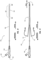
- FIGS. 1 and 2 illustrate side and top or bottom views of a balloon protector 100 in accordance with some embodiments.
- FIGS. 3 and 4 illustrate detailed side and top or bottom views of a distal-end portion of the balloon protector 100 in accordance with some embodiments.
- FIG. 5 illustrates a longitudinal cross section of the distal-end portion of the balloon protector 100;
- FIG. 6 illustrates a transverse cross section of the distal-end portion of the balloon protector where a tip piece 104 overlaps a distal-end portion of a body piece 102;
- FIG. 7 illustrates a transverse cross section of a distal-end portion of the tip piece 104 of the balloon protector 100 in accordance with some embodiments.
- the balloon protector 100 is configured to cover and protect a drug-coated balloon of a balloon catheter (e.g., the balloon catheter 800 of FIG. 8 ) during shipping or preoperative handling, which is needed to maintain integrity of the balloon catheter for the surgical procedures for which it is designed.
- a drug-coated balloon of a balloon catheter e.g., the balloon catheter 800 of FIG. 8
- the balloon protector 100 includes the body piece 102 and the tip piece 104 coupled to a distal-end portion of the body piece 102.
- Each piece of the body piece 102 and the tip piece 104 is unitary in that it is one continuous piece.
- a balloon-covering section 106 of the balloon protector 100 includes the tip piece 104 and a distal portion of the body piece 102.
- the balloon-covering section 106 also includes a transitional section 108 of the body piece 102 opposite the tip piece 104.
- a tabbed section 110 of the balloon protector 100 includes a proximal portion of the body piece 102.
- the balloon-covering section 106 is configured to cover a balloon of a balloon catheter, which balloon is typically disposed about a distal-end portion of a shaft of the balloon catheter.
- the balloon-covering section 106 is configured to cover the balloon of such a balloon catheter with at least a clearance fit (e.g., a sliding fit, location fit, etc.) up to a transition fit (e.g., tight fit), thereby holding the balloon in an uninflated, folded configuration without compressing the balloon up to minimally compressing the balloon.
- the balloon-covering section 106 of the balloon protector 100 has an inner diameter minimally larger than an outer diameter of the balloon in the uninflated, folded configuration.
- the inner diameter of the balloon-covering section 106 is negligibly larger than the outer diameter of the balloon in the uninflated, folded configuration. ( See International Organization for Standardization ["ISO"] 2768 for such tolerances.)
- the tip piece 104 of the balloon protector 100 is configured to cover a distal shoulder of a balloon of a balloon catheter, which shoulder typically does not include a drug coating.
- the tip piece 104 is coupled (e.g., adhered, solvent bonded, heat welded, etc.) to a distal-end portion of the body piece 102 of the balloon protector 100 such that the tip piece 104 has an overlapping portion 112 over the distal-end portion of the body piece 102.
- the overlapping portion 112 has an outer diameter greater than that of an immediately proximal portion of the balloon-covering section 106 of the balloon protector 100.
- the outer diameter of the overlapping portion 112 of the tip piece 104 is configured to provide a stop to prevent insertion of the balloon catheter into an introducer sheath while the balloon protector 100 is covering the balloon.
- the stop is advantageous in that it is preferential to leave a balloon protector over a balloon of a balloon catheter up until the very moment the balloon catheter is inserted into the introducer sheath in order to protect the balloon from fluids (e.g., saline, bodily fluids, etc.), wet instruments, wet hands, or the like.
- the stop allows a clinician to leave the balloon protector over the balloon of the balloon catheter as long as desired without a risk of inadvertently inserting the balloon catheter into the introducer sheath while the balloon protector 100 is covering the balloon.
- the tip piece 104 has a tapered portion 114 tapering from the overlapping portion 112 of the tip piece 104 to a distal tip 116 of the tip piece 104.
- the tapered portion 114 of the tip piece 104 has an inner-diameter taper commensurate with an outer diameter of a distal shoulder of a balloon of a balloon catheter.
- the inner-diameter taper of the tapered portion 114 is configured to maintain concentricity between an opening 118 in the distal tip 116 and an opening in a distal end of a shaft of the balloon catheter for threading a guidewire therethrough.
- the tapered portion 114 also has an outer-diameter taper.
- the outer-diameter taper can be greater than, equal to, or less than the inner-diameter taper.
- the outer-diameter taper is greater than the inner-diameter taper of the balloon protector 100 shown in FIG. 5 .
- the tip piece 104 and the tapered portion 114 thereof facilitate stylet removal.
- the tip piece 104 includes a longitudinal gap 120 on each side of two opposing sides of the balloon protector 100.
- the longitudinal gap 120 of the tip piece 104 has a length equal to or greater than that of the overlapping portion 112 of the tip piece 104 as measured from a proximal end of the tip piece 104.
- the length of the longitudinal gap 120 allows the distal-end portion of the body piece 102 of the balloon protector 100 to be split through a distal end thereof without the increase in applied peel force that would otherwise be required to split through both the overlapping portion 112 of the tip piece 104 and the distal-end portion of the body piece 102 thereunder.
- a window or through hole 121 is formed between a distal end of the longitudinal gap 120 and the distal end of the body piece 102.
- the through hole 121 advantageously provides a momentary break in the applied peel force (e.g., ⁇ 1.5 lbf to 0 lbf) when splitting the balloon protector 100 in a distal direction along the balloon-covering section 106 thereof.
- the break signals the distal end of the body piece 102 has been split through, which, in turn, signals near completion of the splitting with commencement of the splitting through the tip piece 104.
- the transitional section 108 of the balloon protector 100 is configured to cover a proximal shoulder of a balloon of a balloon catheter, which shoulder typically does not include a drug coating.
- the transitional section 108 has a flare in at least an outer diameter thereof from an immediately distal portion of the balloon-covering section 106 of the balloon protector 100 to a distal end of the tabbed section 110 of the balloon protector 100.
- the flare of the transitional section 108 is configured to increase a distance between each tab of a pair of tabs 122 of the tabbed section 110 of the balloon protector 100, thereby making the tabs 122 easier to grasp for splitting the balloon protector 100.
- the flare of the transitional section 108 is also configured to facilitate manufacturing of catheter assemblies such as the catheter assembly 900 set forth below.
- the flare of the transitional section 108 ensures the drug coating 833 of the balloon 832 is not unnecessarily scraped off when the balloon protector 100 is disposed over the balloon 832.
- the transitional section 108 minimizes any potential for damage of the balloon 832 while in the uninflated state.
- the tabbed section 110 of the balloon protector 100 includes the pair of tabs 122, which tabs 122 are configured to provide a starting point from which to split the balloon-covering section 106 of the balloon protector 100 along the pairs of lines of weakness 124 and 126 set forth below. Indeed, the tabs 122 are configured to be grasped and continuously pulled away from each other to progressively split the balloon protector 100 in a distal direction along the balloon-covering section 106 of the balloon protector 100 until the balloon protector 100 is completely peeled off a balloon of a balloon catheter.
- the tabbed section 110 has a flare configured to increase a distance between each tab of the pair of tabs 122 of the tabbed section 110, thereby making the tabs 122 easier to grasp for splitting the balloon protector 100.
- each tab of the pair of tabs 122 includes an inner surface and an outer surface. Any surface of the inner and outer surfaces of each tab or both surfaces of each tab can be textured making the tabs 122 easier to grasp for splitting the balloon protector 100. In the embodiment of the balloon protector 100 shown in at least FIGS. 1, 2 , and 9 , both the inner surface and the outer surface of each tab of the pair of tabs 122 is textured.
- the body piece 102 along the balloon-covering section 106 of the balloon protector 100 includes a pair of opposing longitudinal lines of weakness 124 aligned with the tabs 122, along which the body piece 102 is configured to split.
- the tip piece 104 of the balloon-covering section 106 of the balloon protector 100 includes a pair of opposing longitudinal lines of weakness 126 aligned with the tabs 122, along which the tip piece 104 is configured to split.
- each line of weakness of the lines of weakness 124 of the body piece 102 extends into the longitudinal gap 120 of the tip piece 104 through the distal end of the body piece 102.
- Each line of weakness of the lines of weakness 126 of the tip piece 104 extends from the distal end of the longitudinal gap 120 of the tip piece 104 through a distal end of the distal tip 116 of the tip piece 104. Should the through hole 121 be present in each side of the balloon protector 100, the through holes provide breaks between the lines of weakness 124 and the lines of weakness 126.
- the lines of weakness 124 and 126 can be scores or perforations along the balloon-covering section 106, wherein the perforations include a series of longitudinal slits akin to a dashed line, a series of through holes akin to a dotted line, or a combination thereof.
- the body piece 102 of the balloon protector 100 lacks the pair of lines of weakness 124
- the tip piece 104 of the balloon protector 100 lacks the pair of lines of weakness 126
- both the body piece 102 and the tip piece 104 lack their respective pair of lines of weakness.
- the body piece 102, the tip piece 104, or each piece of the body piece 102 and the tip piece 104 is formed of a polymeric material in which main chains of the polymeric material are oriented along a length of the body piece 102 or the tip piece 104.
- the main chains of the polymeric material are configured to facilitate splitting from a starting point provided by, for example, the pair of tabs 122 when pulled away from each other, through a remainder of the body piece 102 or the tip piece 104 without transversely tearing the body piece 102 or the tip piece 104.
- Each piece of the body piece 102 and the tip piece 104 of the balloon protector 100 can be of a polymeric material including, but not limited to, high-density polyethylene (“HDPE”) or expanded polytetrafluoroethylene (“ePTFE").
- HDPE high-density polyethylene
- ePTFE expanded polytetrafluoroethylene
- main chains of the ePTFE can be oriented along the length of the body piece 102 or the tip piece 104 to facilitate splitting thereof without the pair of lines of weakness 124 or 126 as set for the above.
- the body piece 102 or the tip piece 104 is molded from the polymeric material, the body piece 102 or the tip piece 104 is characteristic of the molding process used such as injection molding, extrusion molding, compression molding, bladder molding, or the like.
- FIG. 8 illustrates a balloon catheter 800 in accordance with some embodiments.
- FIG. 9 illustrates a catheter assembly 900 including the balloon catheter 800 and the balloon protector 100 in accordance with some embodiments.
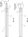
- FIG. 10 illustrates a detailed side view of the catheter assembly 900 including a stylet 928 in accordance with some embodiments.
- the catheter assembly 900 includes the balloon catheter 800, the balloon protector 100, and, optionally, the stylet 928 to maintain integrity of the catheter assembly 900 during shipping or preoperative handling.
- the balloon catheter 800 includes a shaft 830, a balloon 832 in an uninflated state disposed about a distal-end portion of the shaft 830, and a bifurcated hub 834 about a proximal-end portion of the shaft 830.
- the balloon 832 of the balloon catheter 800 can be a drug-coated balloon, wherein a drug coating 833 of the balloon 832 is a coating of an anti-proliferative or anti-restenotic drug such as paclitaxel or rapamycin.
- the balloon 832 includes a proximal shoulder 836 and a distal shoulder 838, between which shoulders 836 and 838 the drug coating 833 of the balloon 832 is typically applied. That is, the proximal shoulder 836 and the distal shoulder 838 of the balloon 832 do not typically include the drug coating 833. This is because the proximal and distal shoulders 836 and 838 are not typically placed in apposition to an arterial-lumen wall during a surgical intervention for atherosclerosis. Notwithstanding the foregoing, the balloon 832 need not include the drug coating 833 in some embodiments.
- the bifurcated hub 834 has an inflation port 840 fluidly connected to the balloon 832 of the balloon catheter 800 by way of an inflation lumen of the shaft 830 of the balloon catheter 800.
- the bifurcated hub 834 also has a guidewire port 842 connected to a guidewire lumen 844 extending along an entire length of the shaft 830 to an opening in a distal end of a shaft 830.
- FIGS. 9 and 10 show the stylet 928 within at least a distal-end portion of the guidewire lumen 844 of the shaft 830.
- the balloon protector 100 is described as set forth above, which includes details with respect to configuration of the balloon protector 100 over a balloon of a balloon catheter such as the balloon catheter 800, as well as details for how the balloon protector 100 is configured to be removed from such a balloon catheter.
- the stylet 928 when present in the catheter assembly 900, is disposed within both the tip piece 104 of the balloon protector 100 and the guidewire lumen 844 of the shaft 830 of the balloon catheter 800 to maintain the integrity of the catheter assembly 900 during shipping or preoperative handling thereof, for example, to prevent collapse of the guidewire lumen 844 of the shaft 830.
- the stylet 928 can be metal (e.g., stainless steel) with a coiled distal-end portion extending from the opening in the distal tip 116 of the tip piece 104 of the balloon protector 100 configured to prevent the stylet 928 from irretrievably slipping into the guidewire lumen 844 of the shaft 830.
- the coiled distal-end portion of the stylet 928 is also configured to provide a handle for grasping and pulling the stylet 928 out of the catheter assembly 900 before use of the catheter assembly 900.
- the tip piece 104 of the balloon protector 100 and the tapered portion 114 thereof advantageously facilitates grasping and pulling the stylet 928 out of the catheter assembly 900, which can be difficult with catheter assemblies such as that of FIG. 11 .
- the catheter assembly of FIG. 11 has a balloon protector with a flared distal-end portion - not a tapered distal-end portion like that of the balloon protector 100.
- the coiled distal-end portion of the stylet 928 can coil into and conceal itself in the flared distal-end portion of the balloon protector of the catheter assembly of FIG. 11 making it difficult to grasp and pull the stylet 928 out of the catheter assembly. Due to the configuration of the tip piece 104, however, the coiled distal-end portion of the stylet 928 remains exposed, thereby facilitating the grasping and pulling of the stylet 928 out of the catheter assembly 900.
- the catheter assembly 900 can be sterilely packaged and ready for immediate use.
- Methods the catheter assembly 900 include a method of using the catheter assembly 900.
- the method of using the catheter assembly 900 includes a removing step of removing the catheter assembly 900 from a package including the catheter assembly 900.
- the catheter assembly 900 includes the balloon catheter 800, the balloon protector 100, and the stylet 928.
- the balloon catheter 800 includes the shaft 830 having the guidewire lumen 844 and the balloon 832 in an uninflated state disposed about the distal-end portion of the shaft 830.
- the balloon 832 includes the drug coating 833 thereon.
- the balloon protector 100 includes the balloon-covering section 106 covering the balloon 832.
- the balloon-covering section 106 includes the tip piece 104 of the balloon protector 100 coupled to the distal-end portion of the body piece 102 of the balloon protector 100.
- the stylet 928 is disposed in the guidewire lumen 844 of the shaft 830 of the balloon catheter 800 to maintain integrity of the catheter assembly 900 during shipping or preoperative handling.
- the stylet 928 has the coiled distal-end portion extending from the opening in the distal tip 116 of the tip piece 104 of the balloon protector 100.
- the method includes a pulling step of pulling the stylet 928 out of the catheter assembly 900 after the removing step.
- the pulling step includes pulling the stylet 928 out of the catheter assembly 900 by the coiled distal-end portion of the stylet 928.
- the method includes a threading step of threading a proximal-end portion of a guidewire through the opening in the distal tip 116 of the tip piece 104 of the balloon protector 100 and into the guidewire lumen 844 of the balloon catheter 800.
- the distal-end portion of the guidewire is typically already disposed in a blood vessel of a patient about a narrowed or obstructed portion of the blood vessel in need of balloon angioplasty.
- the catheter assembly of FIG. 11 has a balloon protector with a flared distal-end portion - not a tapered distal-end portion like that of the balloon protector 100.
- the flared distal-end portion of the balloon protector can conceal a distal-end portion of a shaft of a balloon catheter and an opening of a guidewire lumen thereof making the threading step difficult with a lot of poking around.
- the tapered portion 114 of the tip piece 104 has the inner-diameter taper commensurate with the outer diameter of the distal shoulder 838 of the balloon 832, which maintains concentricity between the opening 118 in the distal tip 116 of the tip piece 104 and the opening in the distal end of the shaft 830 of the balloon catheter 800, thereby further facilitating the threading step.
- the method includes a catheter-assembly advancing step of advancing the catheter assembly 900 over the guidewire up to an opening in a proximal end of an introducer sheath.
- the tip piece 104 of the balloon protector 100 has the overlapping portion 112 over the distal-end portion of the body piece 102 of the balloon protector 100 with an outer diameter greater than that of an immediately proximal portion of the balloon-covering section 106 of the balloon protector 100.
- the overlapping portion 112 is configured to stop the advancing of the catheter assembly 900 into the introducer sheath with the balloon protector 100 covering the balloon 832.
- the method includes a peeling step of peeling the balloon protector 100 off the balloon catheter 800 by continuously pulling the pair of tabs 122 of the tabbed section 110 of the balloon protector 100 away from each other to progressively split the balloon protector 100.
- both the body piece 102 and the tip piece 104 of the balloon-covering section 106 of the balloon protector 100 include the pairs of lines of weakness 124 and 126 aligned with the tabs 122.
- the balloon-covering section 106 is configured to split along each line of the lines of weakness 124 and 126.
- the method can further include a balloon-catheter advancing step of advancing the balloon 832 of the balloon catheter 800 over the guidewire to the narrowed or obstructed portion of the blood vessel in need of balloon angioplasty.
- the method can include an inflating step of inflating the balloon 832 to widen the narrowed or obstructed portion of the blood vessel.
- the balloon catheter 800 includes the bifurcated hub 834 over a proximal-end portion of the shaft 830 including the inflation port 840 fluidly connected to the balloon 832 by way of the inflation lumen of the shaft 830, which inflation port 840 is used for the inflating step.
Landscapes
- Health & Medical Sciences (AREA)
- Life Sciences & Earth Sciences (AREA)
- Heart & Thoracic Surgery (AREA)
- Biomedical Technology (AREA)
- Biophysics (AREA)
- Pulmonology (AREA)
- Engineering & Computer Science (AREA)
- Anesthesiology (AREA)
- Hematology (AREA)
- Animal Behavior & Ethology (AREA)
- General Health & Medical Sciences (AREA)
- Public Health (AREA)
- Veterinary Medicine (AREA)
- Child & Adolescent Psychology (AREA)
- Media Introduction/Drainage Providing Device (AREA)
- Ultra Sonic Daignosis Equipment (AREA)
Description
- This application claims the benefit of priority to
U.S. Patent Application No. 62/969,900, filed February 4, 2020 - Atherosclerosis is characterized by one or more intravascular lesions formed in part of plaque including blood-borne substances such as fat, cholesterol, and calcium. An intravascular lesion such as an arterial lesion can form on a wall of an arterial lumen and build out across the lumen to an opposite wall thereof. A last point of patency often occurs at a boundary between the arterial lesion and the opposite wall of the arterial lumen. Surgical procedures for atherosclerosis such as balloon angioplasty with drug-coated balloons can be used to restore patency and blood flow lost to the one or more intravascular lesions.
- Balloon protectors are designed to cover and protect the drug-coated balloons of balloon catheters during shipping or preoperative handling, which is needed to maintain integrity of the balloon catheters for the surgical procedures for which they are designed. In addition, balloon protectors protect clinicians and others from inadvertently coming into contact with anti-proliferative drugs of the drug-coated balloons when handling the balloon catheters before the surgical procedures. While the foregoing needs for balloon protectors continue to exist, additional needs exist such as a need to safeguard against advancing a balloon catheter through an introducer sheath without first removing the balloon protector thereof.
-
US 6,110,146 discloses a balloon protector for the balloon of a dilatation catheter including a distally extending flared section that defines a funnel receptive to a guidewire in order to facilitate backloading of the guidewire into the catheter.WO2014/179767 discloses a peelable protective sheath for protecting balloon of angioplasty dilatation catheter for treating blockages in arteries of patient, has tab extending axially from body portion and including textured surface on side facing away from axis. - Disclosed herein are balloon protectors, balloon catheters including the balloon protectors, and methods thereof that meet or exceed the foregoing needs.
- The present invention is directed to the catheter assembly of claim 1. The dependent claims refer to preferred embodiments.
- Disclosed herein is a balloon protector for a balloon catheter. The balloon protector includes a balloon-covering section and a tabbed section proximal of the balloon-covering section. The balloon-covering section is configured to cover a drug-coated balloon of the balloon catheter. The balloon-covering section includes a tip piece of the balloon protector. The tabbed section includes a pair of tabs configured to be continuously pulled away from each other to progressively split the balloon protector along the balloon-covering section until the balloon protector is completely peeled off the balloon.
- In some embodiments, the tip piece has a tapered portion having an inner-diameter taper (configured to be) commensurate with an outer diameter of a distal shoulder of the balloon. The inner-diameter taper of the tip piece is configured to maintain concentricity between an opening in a distal end of the tip piece and an opening in a distal end of a shaft of the balloon catheter for threading a guidewire therethrough.
- In some embodiments, the tip piece has an overlapping portion over the distal-end portion of the body piece. In other words, the overlapping portion partially overlaps the distal-end portion of the body piece. The overlapping portion has an outer diameter greater than that of an immediately proximal portion of the balloon-covering section. The outer diameter of the overlapping portion of the tip piece is configured to provide a stop to prevent insertion of the balloon catheter into an introducer sheath while the balloon protector is covering the balloon.
- In some embodiments, the tip piece includes a longitudinal gap on each side of two opposing sides of the balloon protector. The longitudinal gap has a length greater than or equal to that of the overlapping portion of the tip piece. The balloon protector is configured such that the length of the longitudinal gap allows the distal-end portion of the body piece to be split through a distal end of the body piece without an increase in applied peel force.
- In some embodiments, the length of the longitudinal gap is greater than that of the overlapping portion of the tip piece. Due to the length of the longitudinal gap, the balloon protector is configured such that a through hole is formed between a distal end of the longitudinal gap and the distal end of the body piece.
- In some embodiments, the balloon protector is configured such that the through hole is configured to provide a break in the applied peel force when splitting the balloon protector along the balloon-covering section, the break signaling splitting through the distal end of the body piece.
- In some embodiments, both the body piece and the tip piece of the balloon-covering section include a pair of opposing longitudinal lines of weakness aligned with the tabs. The balloon protector is configured such that the balloon-covering section is configured to split along each line of the lines of weakness.
- In some embodiments, the balloon-covering section further includes a transitional section configured to cover a proximal shoulder of the balloon. The transitional section has an outer-diameter flare from an (immediately) distal portion of the balloon-covering section to a distal end of the tabbed section. The outer-diameter flare is configured to increase a distance between the tabs. This is optional for making the tabs easier to grasp.
- In some embodiments, each tab of the pair of tabs includes an inner surface and an outer surface. The inner and outer surfaces of each tab are optionally textured. This is optional for making the tabs easier to grasp.
- The catheter assembly of claim 1 includes a balloon catheter and a balloon protector. The balloon catheter includes a shaft and a drug-coated balloon in an uninflated state disposed about a distal-end portion of the shaft. The balloon protector can be the balloon protector of any of the foregoing paragraphs [0004] to [0012]. The balloon protector includes a balloon-covering section and a tabbed section proximal of the balloon-covering section. The balloon-covering section covers the balloon of the balloon catheter. The balloon-covering section includes a tip piece of the balloon protector coupled to a distal-end portion of a body piece of the balloon protector. The tabbed section includes a pair of tabs configured to be continuously pulled away from each other to progressively split the balloon protector along the balloon-covering section until the balloon protector is completely peeled off the balloon.
- According to claim 1, the tip piece has a tapered portion having an inner-diameter taper commensurate with an outer diameter of a distal shoulder of the balloon. The inner-diameter taper of the tip piece is configured to maintain concentricity between an opening in a distal end of the tip piece and an opening in a distal end of a shaft of the balloon catheter for threading a guidewire therethrough.
- In some embodiments, the catheter assembly further includes a stylet disposed in a guidewire lumen of the shaft of the balloon catheter such that the catheter assembly is configured to maintain integrity of the catheter assembly during shipping or preoperative handling. The stylet has a coiled distal-end portion extending from the opening in the distal end of the tip piece of the balloon protector configured to be grasped for pulling the stylet out of the catheter assembly.
- In some embodiments, the tip piece has an overlapping portion over the distal-end portion of the body piece. The overlapping portion has an outer diameter greater than that of an immediately proximal portion of the balloon-covering section. The outer diameter of the overlapping portion of the tip piece is configured to provide a stop to prevent insertion of the balloon catheter into an introducer sheath while the balloon protector is covering the balloon.
- In some embodiments, the tip piece includes a longitudinal gap on each side of two opposing sides of the balloon protector. The longitudinal gap has a length greater than or equal to that of the overlapping portion of the tip piece. The length of the longitudinal gap allows the distal-end portion of the body piece to be split through a distal end of the body piece without an increase in applied peel force.
- In some embodiments, the length of the longitudinal gap is greater than that of the overlapping portion of the tip piece. Due to the length of the longitudinal gap, a through hole is formed between a distal end of the longitudinal gap and the distal end of the body piece.
- In some embodiments, the through hole is configured to provide a break in the applied peel force when splitting the balloon protector along the balloon-covering section, the break signaling splitting through the distal end of the body piece.
- In some embodiments, both the body piece and the tip piece of the balloon-covering section include a pair of opposing longitudinal lines of weakness aligned with the tabs. The balloon-covering section is configured to split along each line of the lines of weakness.
- In some embodiments, the balloon-covering section further includes a transitional section configured to cover a proximal shoulder of the balloon. The transitional section has an outer-diameter flare from an immediately distal portion of the balloon-covering section to a distal end of the tabbed section. The outer-diameter flare is configured to increase a distance between the tabs making the tabs easier to grasp.
- In some embodiments, each tab of the pair of tabs includes an inner surface and an outer surface. The inner and outer surfaces of each tab are optionally textured making the tabs easier to grasp.
- In some embodiments, the balloon catheter further includes a bifurcated hub about a proximal-end portion of the shaft. The bifurcated hub has an inflation port fluidly connected to the balloon by way of an inflation lumen of the shaft.
- Also disclosed herein is a method of a catheter assembly including, in some embodiments, a removing step of removing the catheter assembly from a catheter-assembly package. The catheter assembly can be a catheter assembly of any of the preceding paragraphs [0013] to [0023]. For example, the catheter assembly includes a balloon catheter, a balloon protector, and a stylet. The balloon catheter includes a shaft having a guidewire lumen and a drug-coated balloon in an uninflated state disposed about a distal-end portion of the shaft. The balloon protector can be a balloon protector of any of the preceding paragraphs [0004] to [0012]. For example, the balloon protector includes a balloon-covering section covering the balloon. The balloon-covering section includes a tip piece of the balloon protector coupled to a distal-end portion of a body piece of the balloon protector. The stylet is disposed in the guidewire lumen of the shaft of the balloon catheter. The stylet has a coiled distal-end portion extending from an opening in a distal end of the tip piece of the balloon protector. The method also includes a pulling step of pulling the stylet out of the catheter assembly by the coiled distal-end portion. The method also includes a threading step of threading a proximal-end portion of a guidewire through the opening in the distal end of the tip piece of the balloon protector and into the guidewire lumen of the balloon catheter.
- In the invention, the tip piece of the balloon protector has a tapered portion having an inner-diameter taper commensurate with an outer diameter of a distal shoulder of the balloon. The inner-diameter taper of the tip piece is configured to maintain concentricity between the opening in the distal end of the tip piece and an opening in a distal end of the shaft of the balloon catheter. Maintaining concentricity facilitates the threading of the guidewire into the guidewire lumen of the balloon catheter.
- In some examples, a distal-end portion of the guidewire is disposed in a blood vessel of a patient about a narrowed or obstructed portion of the blood vessel in need of balloon angioplasty.
- In some examples, the method further includes a balloon-catheter advancing step of advancing the balloon catheter over the guidewire to the narrowed or obstructed portion of the blood vessel in need of balloon angioplasty. The method also includes an inflating step of inflating the balloon to widen the narrowed or obstructed portion of the blood vessel. The balloon catheter includes a bifurcated hub over a proximal-end portion of the shaft including an inflation port fluidly connected to the balloon by way of an inflation lumen of the shaft.
- In some examples, the method further includes a catheter-assembly advancing step of advancing the catheter assembly over the guidewire up to an opening in a proximal end of an introducer sheath. The tip piece of the balloon protector has an overlapping portion over the distal-end portion of the body piece with an outer diameter greater than that of an immediately proximal portion of the balloon-covering section. The overlapping portion is configured to stop the advancing of the catheter assembly into the introducer sheath with the balloon protector covering the balloon.
- In some examples, the method further includes a peeling step of peeling the balloon protector off the balloon catheter by continuously pulling a pair of tabs away from each other to progressively split the balloon protector. The balloon protector includes a tabbed section proximal of the balloon-covering section including the pair of tabs.
- In some examples, both the body piece and the tip piece of the balloon-covering section of the balloon protector include a pair of opposing longitudinal lines of weakness aligned with the tabs. The balloon-covering section is configured to split along each line of the lines of weakness.
- These and other features of the concepts provided herein will become more apparent to those of skill in the art in view of the accompanying drawings and following description, which disclose particular embodiments of such concepts in greater detail.
-
-
FIG. 1 illustrates a side view of a balloon protector in accordance with some embodiments. -
FIG. 2 illustrates a top or bottom view of the balloon protector in accordance with some embodiments. -
FIG. 3 illustrates a detailed side view of a distal-end portion of the balloon protector in accordance with some embodiments. -
FIG. 4 illustrates a detailed top or bottom view of the distal-end portion of the balloon protector in accordance with some embodiments. -
FIG. 5 illustrates a longitudinal cross section of the distal-end portion of the balloon protector in accordance with the invention. -
FIG. 6 illustrates a transverse cross section of the distal-end portion of the balloon protector where a tip piece overlaps a distal-end portion of a body piece in accordance with some embodiments. -
FIG. 7 illustrates a transverse cross section of a distal-end portion of the tip piece of the balloon protector in accordance with some embodiments. -
FIG. 8 illustrates an exemplary balloon catheter. -
FIG. 9 illustrates a catheter assembly including the balloon catheter and the balloon protector in accordance with some embodiments. -
FIG. 10 illustrates a detailed side view of the catheter assembly including a stylet in accordance with some embodiments. -
FIG. 11 illustrates a detailed side view of an existing catheter assembly including a stylet in accordance with some examples. - Before some particular embodiments are disclosed in greater detail, it should be understood that the particular embodiments disclosed herein do not limit the scope of the concepts provided herein. It should also be understood that a particular embodiment disclosed herein can have features that can be readily separated from the particular embodiment and optionally combined with or substituted for features of any of a number of other embodiments disclosed herein.
- Regarding terms used herein, it should also be understood the terms are for the purpose of describing some particular embodiments, and the terms do not limit the scope of the concepts provided herein. Ordinal numbers (e.g., first, second, third, etc.) are generally used to distinguish or identify different features or steps in a group of features or steps, and do not supply a serial or numerical limitation. For example, "first," "second," and "third" features or steps need not necessarily appear in that order, and the particular embodiments including such features or steps need not necessarily be limited to the three features or steps. Labels such as "left," "right," "front," "back," "top," "bottom," "proximal," "distal," and the like, are used for convenience and are not intended to imply, for example, any particular fixed location, orientation, or direction. Instead, such labels are used to reflect, for example, relative location, orientation, or directions. Singular forms of "a," "an," and "the" include plural references unless the context clearly dictates otherwise.
- With respect to "proximal," a "proximal portion" or a "proximal-end portion" of, for example, a catheter disclosed herein includes a portion of the catheter intended to be near a clinician when the catheter is used on a patient. Likewise, a "proximal length" of, for example, the catheter includes a length of the catheter intended to be near the clinician when the catheter is used on the patient. A "proximal end" of, for example, the catheter includes an end of the catheter intended to be near the clinician when the catheter is used on the patient. The proximal portion, the proximal-end portion, or the proximal length of the catheter can include the proximal end of the catheter; however, the proximal portion, the proximal-end portion, or the proximal length of the catheter need not include the proximal end of the catheter. That is, unless context suggests otherwise, the proximal portion, the proximal-end portion, or the proximal length of the catheter is not a terminal portion or terminal length of the catheter.
- With respect to "distal," a "distal portion" or a "distal-end portion" of, for example, a catheter disclosed herein includes a portion of the catheter intended to be near or in a patient when the catheter is used on the patient. Likewise, a "distal length" of, for example, the catheter includes a length of the catheter intended to be near or in the patient when the catheter is used on the patient. A "distal end" of, for example, the catheter includes an end of the catheter intended to be near or in the patient when the catheter is used on the patient. The distal portion, the distal-end portion, or the distal length of the catheter can include the distal end of the catheter; however, the distal portion, the distal-end portion, or the distal length of the catheter need not include the distal end of the catheter. That is, unless context suggests otherwise, the distal portion, the distal-end portion, or the distal length of the catheter is not a terminal portion or terminal length of the catheter.
- Unless defined otherwise, all technical and scientific terms used herein have the same meaning as commonly understood by those of ordinary skill in the art.
- Again, balloon protectors are designed to cover and protect the drug-coated balloons of balloon catheters during shipping or preoperative handling, which is needed to maintain integrity of the balloon catheters for the surgical procedures for which they are designed. In addition, balloon protectors protect clinicians and others from inadvertently coming into contact with anti-proliferative drugs of the drug-coated balloons when handling the balloon catheters before the surgical procedures. While the foregoing needs for balloon protectors continue to exist, additional needs exist such as a need to safeguard against advancing a balloon catheter through an introducer sheath without first removing the balloon protector thereof.
- Disclosed herein are balloon protectors, balloon catheters including the balloon protectors, and methods thereof that meet or exceed the foregoing needs.
-
FIGS. 1 and 2 illustrate side and top or bottom views of aballoon protector 100 in accordance with some embodiments.FIGS. 3 and 4 illustrate detailed side and top or bottom views of a distal-end portion of theballoon protector 100 in accordance with some embodiments.FIG. 5 illustrates a longitudinal cross section of the distal-end portion of theballoon protector 100;FIG. 6 illustrates a transverse cross section of the distal-end portion of the balloon protector where atip piece 104 overlaps a distal-end portion of abody piece 102; andFIG. 7 illustrates a transverse cross section of a distal-end portion of thetip piece 104 of theballoon protector 100 in accordance with some embodiments. - The
balloon protector 100 is configured to cover and protect a drug-coated balloon of a balloon catheter (e.g., theballoon catheter 800 ofFIG. 8 ) during shipping or preoperative handling, which is needed to maintain integrity of the balloon catheter for the surgical procedures for which it is designed. - As shown, the
balloon protector 100 includes thebody piece 102 and thetip piece 104 coupled to a distal-end portion of thebody piece 102. Each piece of thebody piece 102 and thetip piece 104 is unitary in that it is one continuous piece. A balloon-coveringsection 106 of theballoon protector 100 includes thetip piece 104 and a distal portion of thebody piece 102. The balloon-coveringsection 106 also includes atransitional section 108 of thebody piece 102 opposite thetip piece 104. A tabbedsection 110 of theballoon protector 100 includes a proximal portion of thebody piece 102. - The balloon-covering
section 106 is configured to cover a balloon of a balloon catheter, which balloon is typically disposed about a distal-end portion of a shaft of the balloon catheter. The balloon-coveringsection 106 is configured to cover the balloon of such a balloon catheter with at least a clearance fit (e.g., a sliding fit, location fit, etc.) up to a transition fit (e.g., tight fit), thereby holding the balloon in an uninflated, folded configuration without compressing the balloon up to minimally compressing the balloon. With respect to the clearance fit, the balloon-coveringsection 106 of theballoon protector 100 has an inner diameter minimally larger than an outer diameter of the balloon in the uninflated, folded configuration. With respect to the transition fit, the inner diameter of the balloon-coveringsection 106 is negligibly larger than the outer diameter of the balloon in the uninflated, folded configuration. (See International Organization for Standardization ["ISO"] 2768 for such tolerances.) - The
tip piece 104 of theballoon protector 100 is configured to cover a distal shoulder of a balloon of a balloon catheter, which shoulder typically does not include a drug coating. Thetip piece 104 is coupled (e.g., adhered, solvent bonded, heat welded, etc.) to a distal-end portion of thebody piece 102 of theballoon protector 100 such that thetip piece 104 has an overlappingportion 112 over the distal-end portion of thebody piece 102. The overlappingportion 112 has an outer diameter greater than that of an immediately proximal portion of the balloon-coveringsection 106 of theballoon protector 100. The outer diameter of the overlappingportion 112 of thetip piece 104 is configured to provide a stop to prevent insertion of the balloon catheter into an introducer sheath while theballoon protector 100 is covering the balloon. The stop is advantageous in that it is preferential to leave a balloon protector over a balloon of a balloon catheter up until the very moment the balloon catheter is inserted into the introducer sheath in order to protect the balloon from fluids (e.g., saline, bodily fluids, etc.), wet instruments, wet hands, or the like. The stop allows a clinician to leave the balloon protector over the balloon of the balloon catheter as long as desired without a risk of inadvertently inserting the balloon catheter into the introducer sheath while theballoon protector 100 is covering the balloon. - The
tip piece 104 has a taperedportion 114 tapering from the overlappingportion 112 of thetip piece 104 to adistal tip 116 of thetip piece 104. The taperedportion 114 of thetip piece 104 has an inner-diameter taper commensurate with an outer diameter of a distal shoulder of a balloon of a balloon catheter. The inner-diameter taper of the taperedportion 114 is configured to maintain concentricity between anopening 118 in thedistal tip 116 and an opening in a distal end of a shaft of the balloon catheter for threading a guidewire therethrough. The taperedportion 114 also has an outer-diameter taper. Depending upon the outer diameter of the overlappingportion 112 of thetip piece 104, a length of thetip piece 104, or the like, the outer-diameter taper can be greater than, equal to, or less than the inner-diameter taper. The outer-diameter taper is greater than the inner-diameter taper of theballoon protector 100 shown inFIG. 5 . As set forth herein below, thetip piece 104 and the taperedportion 114 thereof facilitate stylet removal. - The
tip piece 104 includes alongitudinal gap 120 on each side of two opposing sides of theballoon protector 100. Thelongitudinal gap 120 of thetip piece 104 has a length equal to or greater than that of the overlappingportion 112 of thetip piece 104 as measured from a proximal end of thetip piece 104. The length of thelongitudinal gap 120 allows the distal-end portion of thebody piece 102 of theballoon protector 100 to be split through a distal end thereof without the increase in applied peel force that would otherwise be required to split through both the overlappingportion 112 of thetip piece 104 and the distal-end portion of thebody piece 102 thereunder. The length of thelongitudinal gap 120 in the embodiment of theballoon protector 100 shown in at leastFIGS. 1 ,3 , and5 is greater than that of the overlappingportion 112. In such embodiments, a window or throughhole 121 is formed between a distal end of thelongitudinal gap 120 and the distal end of thebody piece 102. The throughhole 121 advantageously provides a momentary break in the applied peel force (e.g., ~1.5 lbf to 0 lbf) when splitting theballoon protector 100 in a distal direction along the balloon-coveringsection 106 thereof. The break signals the distal end of thebody piece 102 has been split through, which, in turn, signals near completion of the splitting with commencement of the splitting through thetip piece 104. - The
transitional section 108 of theballoon protector 100 is configured to cover a proximal shoulder of a balloon of a balloon catheter, which shoulder typically does not include a drug coating. Thetransitional section 108 has a flare in at least an outer diameter thereof from an immediately distal portion of the balloon-coveringsection 106 of theballoon protector 100 to a distal end of the tabbedsection 110 of theballoon protector 100. The flare of thetransitional section 108 is configured to increase a distance between each tab of a pair oftabs 122 of the tabbedsection 110 of theballoon protector 100, thereby making thetabs 122 easier to grasp for splitting theballoon protector 100. The flare of thetransitional section 108 is also configured to facilitate manufacturing of catheter assemblies such as thecatheter assembly 900 set forth below. Indeed, the flare of thetransitional section 108 ensures thedrug coating 833 of theballoon 832 is not unnecessarily scraped off when theballoon protector 100 is disposed over theballoon 832. In addition, thetransitional section 108 minimizes any potential for damage of theballoon 832 while in the uninflated state. - The tabbed
section 110 of theballoon protector 100 includes the pair oftabs 122, whichtabs 122 are configured to provide a starting point from which to split the balloon-coveringsection 106 of theballoon protector 100 along the pairs of lines ofweakness tabs 122 are configured to be grasped and continuously pulled away from each other to progressively split theballoon protector 100 in a distal direction along the balloon-coveringsection 106 of theballoon protector 100 until theballoon protector 100 is completely peeled off a balloon of a balloon catheter. Like the flare of thetransitional section 108 of theballoon protector 100, the tabbedsection 110 has a flare configured to increase a distance between each tab of the pair oftabs 122 of the tabbedsection 110, thereby making thetabs 122 easier to grasp for splitting theballoon protector 100. In addition, each tab of the pair oftabs 122 includes an inner surface and an outer surface. Any surface of the inner and outer surfaces of each tab or both surfaces of each tab can be textured making thetabs 122 easier to grasp for splitting theballoon protector 100. In the embodiment of theballoon protector 100 shown in at leastFIGS. 1, 2 , and9 , both the inner surface and the outer surface of each tab of the pair oftabs 122 is textured. - The
body piece 102 along the balloon-coveringsection 106 of theballoon protector 100 includes a pair of opposing longitudinal lines ofweakness 124 aligned with thetabs 122, along which thebody piece 102 is configured to split. Likewise, thetip piece 104 of the balloon-coveringsection 106 of theballoon protector 100 includes a pair of opposing longitudinal lines ofweakness 126 aligned with thetabs 122, along which thetip piece 104 is configured to split. Notably, each line of weakness of the lines ofweakness 124 of thebody piece 102 extends into thelongitudinal gap 120 of thetip piece 104 through the distal end of thebody piece 102. Each line of weakness of the lines ofweakness 126 of thetip piece 104 extends from the distal end of thelongitudinal gap 120 of thetip piece 104 through a distal end of thedistal tip 116 of thetip piece 104. Should the throughhole 121 be present in each side of theballoon protector 100, the through holes provide breaks between the lines ofweakness 124 and the lines ofweakness 126. The lines ofweakness section 106, wherein the perforations include a series of longitudinal slits akin to a dashed line, a series of through holes akin to a dotted line, or a combination thereof. - In an alternative to the foregoing, the
body piece 102 of theballoon protector 100 lacks the pair of lines ofweakness 124, thetip piece 104 of theballoon protector 100 lacks the pair of lines ofweakness 126, or both thebody piece 102 and thetip piece 104 lack their respective pair of lines of weakness. Instead, thebody piece 102, thetip piece 104, or each piece of thebody piece 102 and thetip piece 104, as the case might be, is formed of a polymeric material in which main chains of the polymeric material are oriented along a length of thebody piece 102 or thetip piece 104. The main chains of the polymeric material are configured to facilitate splitting from a starting point provided by, for example, the pair oftabs 122 when pulled away from each other, through a remainder of thebody piece 102 or thetip piece 104 without transversely tearing thebody piece 102 or thetip piece 104. - Each piece of the
body piece 102 and thetip piece 104 of theballoon protector 100 can be of a polymeric material including, but not limited to, high-density polyethylene ("HDPE") or expanded polytetrafluoroethylene ("ePTFE"). When either thebody piece 102 or thetip piece 104 is of ePTFE, main chains of the ePTFE can be oriented along the length of thebody piece 102 or thetip piece 104 to facilitate splitting thereof without the pair of lines ofweakness body piece 102 or thetip piece 104 is molded from the polymeric material, thebody piece 102 or thetip piece 104 is characteristic of the molding process used such as injection molding, extrusion molding, compression molding, bladder molding, or the like. -
FIG. 8 illustrates aballoon catheter 800 in accordance with some embodiments.FIG. 9 illustrates acatheter assembly 900 including theballoon catheter 800 and theballoon protector 100 in accordance with some embodiments.FIG. 10 illustrates a detailed side view of thecatheter assembly 900 including astylet 928 in accordance with some embodiments. - The
catheter assembly 900 includes theballoon catheter 800, theballoon protector 100, and, optionally, thestylet 928 to maintain integrity of thecatheter assembly 900 during shipping or preoperative handling. - The
balloon catheter 800 includes ashaft 830, aballoon 832 in an uninflated state disposed about a distal-end portion of theshaft 830, and abifurcated hub 834 about a proximal-end portion of theshaft 830. - The
balloon 832 of theballoon catheter 800 can be a drug-coated balloon, wherein adrug coating 833 of theballoon 832 is a coating of an anti-proliferative or anti-restenotic drug such as paclitaxel or rapamycin. Theballoon 832 includes aproximal shoulder 836 and adistal shoulder 838, between which shoulders 836 and 838 thedrug coating 833 of theballoon 832 is typically applied. That is, theproximal shoulder 836 and thedistal shoulder 838 of theballoon 832 do not typically include thedrug coating 833. This is because the proximal anddistal shoulders balloon 832 need not include thedrug coating 833 in some embodiments. - The
bifurcated hub 834 has aninflation port 840 fluidly connected to theballoon 832 of theballoon catheter 800 by way of an inflation lumen of theshaft 830 of theballoon catheter 800. Thebifurcated hub 834 also has aguidewire port 842 connected to aguidewire lumen 844 extending along an entire length of theshaft 830 to an opening in a distal end of ashaft 830.FIGS. 9 and10 show thestylet 928 within at least a distal-end portion of theguidewire lumen 844 of theshaft 830. - The
balloon protector 100 is described as set forth above, which includes details with respect to configuration of theballoon protector 100 over a balloon of a balloon catheter such as theballoon catheter 800, as well as details for how theballoon protector 100 is configured to be removed from such a balloon catheter. - The
stylet 928, when present in thecatheter assembly 900, is disposed within both thetip piece 104 of theballoon protector 100 and theguidewire lumen 844 of theshaft 830 of theballoon catheter 800 to maintain the integrity of thecatheter assembly 900 during shipping or preoperative handling thereof, for example, to prevent collapse of theguidewire lumen 844 of theshaft 830. Thestylet 928 can be metal (e.g., stainless steel) with a coiled distal-end portion extending from the opening in thedistal tip 116 of thetip piece 104 of theballoon protector 100 configured to prevent thestylet 928 from irretrievably slipping into theguidewire lumen 844 of theshaft 830. The coiled distal-end portion of thestylet 928 is also configured to provide a handle for grasping and pulling thestylet 928 out of thecatheter assembly 900 before use of thecatheter assembly 900. - As shown by contrast between
FIGS. 10 and 11 , thetip piece 104 of theballoon protector 100 and the taperedportion 114 thereof advantageously facilitates grasping and pulling thestylet 928 out of thecatheter assembly 900, which can be difficult with catheter assemblies such as that ofFIG. 11 . For example, the catheter assembly ofFIG. 11 has a balloon protector with a flared distal-end portion - not a tapered distal-end portion like that of theballoon protector 100. The coiled distal-end portion of thestylet 928 can coil into and conceal itself in the flared distal-end portion of the balloon protector of the catheter assembly ofFIG. 11 making it difficult to grasp and pull thestylet 928 out of the catheter assembly. Due to the configuration of thetip piece 104, however, the coiled distal-end portion of thestylet 928 remains exposed, thereby facilitating the grasping and pulling of thestylet 928 out of thecatheter assembly 900. - The
catheter assembly 900 can be sterilely packaged and ready for immediate use. - Methods the
catheter assembly 900 include a method of using thecatheter assembly 900. - For example, the method of using the
catheter assembly 900 includes a removing step of removing thecatheter assembly 900 from a package including thecatheter assembly 900. For the purpose of this example method, thecatheter assembly 900 includes theballoon catheter 800, theballoon protector 100, and thestylet 928. Theballoon catheter 800 includes theshaft 830 having theguidewire lumen 844 and theballoon 832 in an uninflated state disposed about the distal-end portion of theshaft 830. Theballoon 832 includes thedrug coating 833 thereon. Theballoon protector 100 includes the balloon-coveringsection 106 covering theballoon 832. The balloon-coveringsection 106 includes thetip piece 104 of theballoon protector 100 coupled to the distal-end portion of thebody piece 102 of theballoon protector 100. Thestylet 928 is disposed in theguidewire lumen 844 of theshaft 830 of theballoon catheter 800 to maintain integrity of thecatheter assembly 900 during shipping or preoperative handling. Thestylet 928 has the coiled distal-end portion extending from the opening in thedistal tip 116 of thetip piece 104 of theballoon protector 100. - The method includes a pulling step of pulling the
stylet 928 out of thecatheter assembly 900 after the removing step. The pulling step includes pulling thestylet 928 out of thecatheter assembly 900 by the coiled distal-end portion of thestylet 928. - The method includes a threading step of threading a proximal-end portion of a guidewire through the opening in the
distal tip 116 of thetip piece 104 of theballoon protector 100 and into theguidewire lumen 844 of theballoon catheter 800. The distal-end portion of the guidewire is typically already disposed in a blood vessel of a patient about a narrowed or obstructed portion of the blood vessel in need of balloon angioplasty. - While not expressly shown, the contrast between
FIGS. 10 and 11 alludes to how thetip piece 104 of theballoon protector 100 and the taperedportion 114 thereof advantageously facilitates the threading step, which can be difficult with catheter assemblies such as that ofFIG. 11 . As set forth above, the catheter assembly ofFIG. 11 has a balloon protector with a flared distal-end portion - not a tapered distal-end portion like that of theballoon protector 100. The flared distal-end portion of the balloon protector can conceal a distal-end portion of a shaft of a balloon catheter and an opening of a guidewire lumen thereof making the threading step difficult with a lot of poking around. Indeed, clinicians often remove such a balloon protector before it is desired to do so in order to perform the threading step, which risks exposing the balloon of the balloon catheter to fluids (e.g., saline, bodily fluids, etc.), wet instruments, wet hands, or the like. Due to the configuration of thetip piece 104, however, theopening 118 in thedistal tip 116 of thetip piece 104 remains exposed, thereby facilitating the threading step (i.e., threading the proximal-end portion of the guidewire through theopening 118 in thedistal tip 116 of thetip piece 104 of theballoon protector 100 and into theguidewire lumen 844 of the balloon catheter 800). Of course, the taperedportion 114 of thetip piece 104 has the inner-diameter taper commensurate with the outer diameter of thedistal shoulder 838 of theballoon 832, which maintains concentricity between the opening 118 in thedistal tip 116 of thetip piece 104 and the opening in the distal end of theshaft 830 of theballoon catheter 800, thereby further facilitating the threading step. - The method includes a catheter-assembly advancing step of advancing the
catheter assembly 900 over the guidewire up to an opening in a proximal end of an introducer sheath. As set forth above, thetip piece 104 of theballoon protector 100 has the overlappingportion 112 over the distal-end portion of thebody piece 102 of theballoon protector 100 with an outer diameter greater than that of an immediately proximal portion of the balloon-coveringsection 106 of theballoon protector 100. The overlappingportion 112 is configured to stop the advancing of thecatheter assembly 900 into the introducer sheath with theballoon protector 100 covering theballoon 832. - The method includes a peeling step of peeling the
balloon protector 100 off theballoon catheter 800 by continuously pulling the pair oftabs 122 of the tabbedsection 110 of theballoon protector 100 away from each other to progressively split theballoon protector 100. As set forth above, both thebody piece 102 and thetip piece 104 of the balloon-coveringsection 106 of theballoon protector 100 include the pairs of lines ofweakness tabs 122. The balloon-coveringsection 106 is configured to split along each line of the lines ofweakness - The method can further include a balloon-catheter advancing step of advancing the
balloon 832 of theballoon catheter 800 over the guidewire to the narrowed or obstructed portion of the blood vessel in need of balloon angioplasty. - The method can include an inflating step of inflating the
balloon 832 to widen the narrowed or obstructed portion of the blood vessel. As set forth above, theballoon catheter 800 includes thebifurcated hub 834 over a proximal-end portion of theshaft 830 including theinflation port 840 fluidly connected to theballoon 832 by way of the inflation lumen of theshaft 830, whichinflation port 840 is used for the inflating step. - While some particular embodiments have been disclosed herein, and while the particular embodiments have been disclosed in some detail, it is not the intention for the particular embodiments to limit the scope of the concepts provided herein. Additional adaptations and/or modifications can appear to those of ordinary skill in the art, and, in broader aspects, these adaptations and/or modifications are encompassed as well. Accordingly, departures may be made from the particular embodiments disclosed herein without departing from the scope of the concepts provided herein.
Claims (10)
- A catheter assembly (900), comprising:a balloon catheter (800) including:a shaft (830); anda drug-coated balloon (832) in an uninflated state disposed about a distal-end portion of the shaft; anda balloon protector (100) including:a balloon-covering section (106) covering the balloon (832), the balloon-covering section (106) including a tip piece (104) of the balloon protector (100) coupled to a distal-end portion of a body piece (102) of the balloon protector (100); anda tabbed section (110) proximal of the balloon-covering section (106), the tabbed section including a pair of tabs (122) configured to be continuously pulled away from each other to progressively split the balloon protector (100) along the balloon-covering section (106) until the balloon protector (100) is completely peeled off the balloon (832),wherein the tip piece (104) has a tapered portion (114) having an inner-diameter taper commensurate with an outer diameter of a distal shoulder (838) of the balloon (832), the inner-diameter taper of the tip piece (104) configured to maintain concentricity between an opening in a distal end (116) of the tip piece (104) and an opening in a distal end of the balloon catheter (800) for threading a guidewire therethrough.
- The catheter assembly of claim 1, further comprising a stylet (928) disposed in a guidewire lumen (844) of the shaft (830) of the balloon catheter (800) to maintain integrity of the catheter assembly (900) during shipping or preoperative handling, the stylet (928) having a coiled distal-end portion extending from the opening in the distal end (116) of the tip piece (104) of the balloon protector configured to be grasped for pulling the stylet (928) out of the catheter assembly (900).
- The catheter assembly of any claim of claims 1-2, wherein the tip piece (104) has an overlapping portion (112) over the distal-end portion of the body piece (102) having an outer diameter greater than that of an immediately proximal portion of the balloon-covering section (112), the outer diameter of the overlapping portion (112) of the tip piece (104) configured to provide a stop to prevent insertion of the balloon catheter (800) into an introducer sheath while the balloon protector (100) is covering the balloon.
- The catheter assembly of claim 3, wherein the tip piece (104) includes a longitudinal gap (120) on each side of two opposing sides of the balloon protector (100), the longitudinal gap (120) having a length greater than or equal to that of the overlapping portion (112) of the tip piece (104) allowing the distal-end portion of the body piece to be split through a distal end of the body piece (102) without an increase in applied peel force.
- The catheter assembly of claim 4, wherein the length of the longitudinal gap (120) is greater than that of the overlapping portion (112) of the tip piece (104), thereby forming a through hole (121) between a distal end of the longitudinal gap (120) and the distal end of the body piece (102).
- The catheter assembly of claim 5, wherein the through hole (121) is configured to provide a break in the applied peel force when splitting the balloon protector (100) along the balloon-covering section, the break signaling splitting through the distal end of the body piece (102).
- The catheter assembly of any claim of claims 1-6, wherein both the body piece (102) and the tip piece (104) of the balloon-covering section include a pair of opposing longitudinal lines of weakness (126) aligned with the tabs (122), the balloon-covering section configured to split along each line of the lines of weakness (126).
- The catheter assembly of any claim of claims 1-7, the balloon-covering section (106) further including a transitional section (108) configured to cover a proximal shoulder (836) of the balloon, the transitional section (108) having an outer-diameter flare from an immediately distal portion of the balloon-covering section (106) to a distal end of the tabbed section (110) configured to increase a distance between the tabs (122) making the tabs easier to grasp.
- The catheter assembly of any claim of claims 1-8, wherein each tab (122) of the pair of tabs includes an inner surface and an outer surface, the inner and outer surfaces of each tab (122) are textured including making the tabs easier to grasp.
- The catheter assembly of any claim of claims 1-9, wherein the balloon catheter (800) further includes a bifurcated hub (834) about a proximal-end portion of the shaft, the bifurcated hub (834) having an inflation port (840) fluidly connected to the balloon by way of an inflation lumen of the shaft (830).
Applications Claiming Priority (2)
| Application Number | Priority Date | Filing Date | Title |
|---|---|---|---|
| US202062969900P | 2020-02-04 | 2020-02-04 | |
| PCT/US2021/014384 WO2021158375A1 (en) | 2020-02-04 | 2021-01-21 | Balloon protectors and balloon-catheter assemblies |
Publications (3)
| Publication Number | Publication Date |
|---|---|
| EP4093479A1 EP4093479A1 (en) | 2022-11-30 |
| EP4093479B1 true EP4093479B1 (en) | 2025-06-18 |
| EP4093479C0 EP4093479C0 (en) | 2025-06-18 |
Family
ID=74595447
Family Applications (1)
| Application Number | Title | Priority Date | Filing Date |
|---|---|---|---|
| EP21705375.0A Active EP4093479B1 (en) | 2020-02-04 | 2021-01-21 | Balloon protectors and balloon-catheter assemblies |
Country Status (7)
| Country | Link |
|---|---|
| US (1) | US20230089857A1 (en) |
| EP (1) | EP4093479B1 (en) |
| JP (1) | JP7711072B2 (en) |
| CN (1) | CN115052652B (en) |
| AU (1) | AU2021216851B2 (en) |
| MX (1) | MX2022009639A (en) |
| WO (1) | WO2021158375A1 (en) |
Families Citing this family (2)
| Publication number | Priority date | Publication date | Assignee | Title |
|---|---|---|---|---|
| US12194255B2 (en) * | 2021-07-09 | 2025-01-14 | Covidien Lp | Expandable-mouth catheter introducer tool |
| WO2025255487A1 (en) * | 2024-06-07 | 2025-12-11 | Terumo Corporation | Loading tool for drug coated balloon |
Citations (3)
| Publication number | Priority date | Publication date | Assignee | Title |
|---|---|---|---|---|
| US20100228333A1 (en) * | 2009-03-04 | 2010-09-09 | William Joseph Drasler | Drug eluting surface covering |
| US20160058983A1 (en) * | 2013-05-03 | 2016-03-03 | C.R. Bard, Inc. | Peelable Protective Sheath |
| US11389627B1 (en) * | 2018-10-02 | 2022-07-19 | Lutonix Inc. | Balloon protectors, balloon-catheter assemblies, and methods thereof |
Family Cites Families (6)
| Publication number | Priority date | Publication date | Assignee | Title |
|---|---|---|---|---|
| US5569294A (en) * | 1994-09-26 | 1996-10-29 | Medtronic, Inc. | Two piece balloon protector |
| JPH1024098A (en) * | 1996-07-10 | 1998-01-27 | Terumo Corp | Balloon and balloon catheter |
| US6110146A (en) * | 1998-09-30 | 2000-08-29 | Medtronic Ave, Inc. | Protector for catheter balloon with guidewire backloading system |
| US20080082083A1 (en) * | 2006-09-28 | 2008-04-03 | Forde Sean T | Perforated expandable implant recovery sheath |
| US10905577B2 (en) * | 2017-04-28 | 2021-02-02 | Covidien Lp | Stent delivery system |
| JP2021036924A (en) * | 2017-12-27 | 2021-03-11 | テルモ株式会社 | Balloon catheter |
-
2021
- 2021-01-21 EP EP21705375.0A patent/EP4093479B1/en active Active
- 2021-01-21 AU AU2021216851A patent/AU2021216851B2/en active Active
- 2021-01-21 MX MX2022009639A patent/MX2022009639A/en unknown
- 2021-01-21 WO PCT/US2021/014384 patent/WO2021158375A1/en not_active Ceased
- 2021-01-21 JP JP2022547280A patent/JP7711072B2/en active Active
- 2021-01-21 US US17/797,416 patent/US20230089857A1/en active Pending
- 2021-01-21 CN CN202180012725.0A patent/CN115052652B/en active Active
Patent Citations (3)
| Publication number | Priority date | Publication date | Assignee | Title |
|---|---|---|---|---|
| US20100228333A1 (en) * | 2009-03-04 | 2010-09-09 | William Joseph Drasler | Drug eluting surface covering |
| US20160058983A1 (en) * | 2013-05-03 | 2016-03-03 | C.R. Bard, Inc. | Peelable Protective Sheath |
| US11389627B1 (en) * | 2018-10-02 | 2022-07-19 | Lutonix Inc. | Balloon protectors, balloon-catheter assemblies, and methods thereof |
Also Published As
| Publication number | Publication date |
|---|---|
| US20230089857A1 (en) | 2023-03-23 |
| JP7711072B2 (en) | 2025-07-22 |
| WO2021158375A1 (en) | 2021-08-12 |
| AU2021216851A1 (en) | 2022-09-01 |
| JP2023514985A (en) | 2023-04-12 |
| EP4093479A1 (en) | 2022-11-30 |
| MX2022009639A (en) | 2022-09-07 |
| CN115052652A (en) | 2022-09-13 |
| CA3168798A1 (en) | 2021-08-12 |
| CN115052652B (en) | 2026-01-06 |
| AU2021216851B2 (en) | 2025-10-09 |
| EP4093479C0 (en) | 2025-06-18 |
Similar Documents
| Publication | Publication Date | Title |
|---|---|---|
| US6110146A (en) | Protector for catheter balloon with guidewire backloading system | |
| JP6723313B2 (en) | Protective sheath that can be peeled off | |
| USRE36857E (en) | Interlocking peel-away dilation catheter | |
| US6613067B1 (en) | Balloon protector | |
| EP2678066B1 (en) | Guidewire loading tool for a catheter | |
| JPH06197972A (en) | Rapidly exchangeable catheter system | |
| CN102573982A (en) | Side branch balloon | |
| US20150265310A1 (en) | Vascular introducer including expandable passage member | |
| CN219323767U (en) | Catheter placement system | |
| AU2021216851B2 (en) | Balloon protectors and balloon-catheter assemblies | |
| US12324883B2 (en) | Expandable balloon sheaths | |
| US20150297875A1 (en) | Vascular dilator systems, kits, and methods | |
| EP3522824B1 (en) | Balloon catheter | |
| CA3168798C (en) | Balloon protectors and balloon-catheter assemblies | |
| US11389627B1 (en) | Balloon protectors, balloon-catheter assemblies, and methods thereof | |
| EP4454609A1 (en) | Peelable advancer for delivery system |
Legal Events
| Date | Code | Title | Description |
|---|---|---|---|
| STAA | Information on the status of an ep patent application or granted ep patent |
Free format text: STATUS: UNKNOWN |
|
| STAA | Information on the status of an ep patent application or granted ep patent |
Free format text: STATUS: THE INTERNATIONAL PUBLICATION HAS BEEN MADE |
|
| PUAI | Public reference made under article 153(3) epc to a published international application that has entered the european phase |
Free format text: ORIGINAL CODE: 0009012 |
|
| STAA | Information on the status of an ep patent application or granted ep patent |
Free format text: STATUS: REQUEST FOR EXAMINATION WAS MADE |
|
| 17P | Request for examination filed |
Effective date: 20220823 |
|
| AK | Designated contracting states |
Kind code of ref document: A1 Designated state(s): AL AT BE BG CH CY CZ DE DK EE ES FI FR GB GR HR HU IE IS IT LI LT LU LV MC MK MT NL NO PL PT RO RS SE SI SK SM TR |
|
| DAV | Request for validation of the european patent (deleted) | ||
| DAX | Request for extension of the european patent (deleted) | ||
| GRAP | Despatch of communication of intention to grant a patent |
Free format text: ORIGINAL CODE: EPIDOSNIGR1 |
|
| STAA | Information on the status of an ep patent application or granted ep patent |
Free format text: STATUS: GRANT OF PATENT IS INTENDED |
|
| INTG | Intention to grant announced |
Effective date: 20250211 |
|
| GRAS | Grant fee paid |
Free format text: ORIGINAL CODE: EPIDOSNIGR3 |
|
| GRAA | (expected) grant |
Free format text: ORIGINAL CODE: 0009210 |
|
| STAA | Information on the status of an ep patent application or granted ep patent |
Free format text: STATUS: THE PATENT HAS BEEN GRANTED |
|
| AK | Designated contracting states |
Kind code of ref document: B1 Designated state(s): AL AT BE BG CH CY CZ DE DK EE ES FI FR GB GR HR HU IE IS IT LI LT LU LV MC MK MT NL NO PL PT RO RS SE SI SK SM TR |
|
| REG | Reference to a national code |
Ref country code: GB Ref legal event code: FG4D |
|
| REG | Reference to a national code |
Ref country code: CH Ref legal event code: EP |
|
| REG | Reference to a national code |
Ref country code: DE Ref legal event code: R096 Ref document number: 602021032427 Country of ref document: DE |
|
| REG | Reference to a national code |
Ref country code: CH Ref legal event code: EP |
|
| REG | Reference to a national code |
Ref country code: IE Ref legal event code: FG4D |
|
| U01 | Request for unitary effect filed |
Effective date: 20250618 |
|
| U07 | Unitary effect registered |
Designated state(s): AT BE BG DE DK EE FI FR IT LT LU LV MT NL PT RO SE SI Effective date: 20250626 |
|
| PG25 | Lapsed in a contracting state [announced via postgrant information from national office to epo] |
Ref country code: NO Free format text: LAPSE BECAUSE OF FAILURE TO SUBMIT A TRANSLATION OF THE DESCRIPTION OR TO PAY THE FEE WITHIN THE PRESCRIBED TIME-LIMIT Effective date: 20250918 Ref country code: GR Free format text: LAPSE BECAUSE OF FAILURE TO SUBMIT A TRANSLATION OF THE DESCRIPTION OR TO PAY THE FEE WITHIN THE PRESCRIBED TIME-LIMIT Effective date: 20250919 |
|
| PG25 | Lapsed in a contracting state [announced via postgrant information from national office to epo] |
Ref country code: HR Free format text: LAPSE BECAUSE OF FAILURE TO SUBMIT A TRANSLATION OF THE DESCRIPTION OR TO PAY THE FEE WITHIN THE PRESCRIBED TIME-LIMIT Effective date: 20250618 |
|
| PG25 | Lapsed in a contracting state [announced via postgrant information from national office to epo] |
Ref country code: RS Free format text: LAPSE BECAUSE OF FAILURE TO SUBMIT A TRANSLATION OF THE DESCRIPTION OR TO PAY THE FEE WITHIN THE PRESCRIBED TIME-LIMIT Effective date: 20250918 |
|
| PG25 | Lapsed in a contracting state [announced via postgrant information from national office to epo] |
Ref country code: IS Free format text: LAPSE BECAUSE OF FAILURE TO SUBMIT A TRANSLATION OF THE DESCRIPTION OR TO PAY THE FEE WITHIN THE PRESCRIBED TIME-LIMIT Effective date: 20251018 |
|
| PG25 | Lapsed in a contracting state [announced via postgrant information from national office to epo] |
Ref country code: SM Free format text: LAPSE BECAUSE OF FAILURE TO SUBMIT A TRANSLATION OF THE DESCRIPTION OR TO PAY THE FEE WITHIN THE PRESCRIBED TIME-LIMIT Effective date: 20250618 |
|
| PG25 | Lapsed in a contracting state [announced via postgrant information from national office to epo] |
Ref country code: CZ Free format text: LAPSE BECAUSE OF FAILURE TO SUBMIT A TRANSLATION OF THE DESCRIPTION OR TO PAY THE FEE WITHIN THE PRESCRIBED TIME-LIMIT Effective date: 20250618 |
|
| PG25 | Lapsed in a contracting state [announced via postgrant information from national office to epo] |
Ref country code: PL Free format text: LAPSE BECAUSE OF FAILURE TO SUBMIT A TRANSLATION OF THE DESCRIPTION OR TO PAY THE FEE WITHIN THE PRESCRIBED TIME-LIMIT Effective date: 20250618 |
|
| PG25 | Lapsed in a contracting state [announced via postgrant information from national office to epo] |
Ref country code: SK Free format text: LAPSE BECAUSE OF FAILURE TO SUBMIT A TRANSLATION OF THE DESCRIPTION OR TO PAY THE FEE WITHIN THE PRESCRIBED TIME-LIMIT Effective date: 20250618 |
|
| PG25 | Lapsed in a contracting state [announced via postgrant information from national office to epo] |
Ref country code: ES Free format text: LAPSE BECAUSE OF FAILURE TO SUBMIT A TRANSLATION OF THE DESCRIPTION OR TO PAY THE FEE WITHIN THE PRESCRIBED TIME-LIMIT Effective date: 20250618 |
|
| PGFP | Annual fee paid to national office [announced via postgrant information from national office to epo] |
Ref country code: GB Payment date: 20260320 Year of fee payment: 6 |
|
| PLBE | No opposition filed within time limit |
Free format text: ORIGINAL CODE: 0009261 |
|
| STAA | Information on the status of an ep patent application or granted ep patent |
Free format text: STATUS: NO OPPOSITION FILED WITHIN TIME LIMIT |
|
| U21 | Renewal fee for the european patent with unitary effect paid with additional fee |
Year of fee payment: 6 Effective date: 20260319 |
|
| REG | Reference to a national code |
Ref country code: CH Ref legal event code: L10 Free format text: ST27 STATUS EVENT CODE: U-0-0-L10-L00 (AS PROVIDED BY THE NATIONAL OFFICE) Effective date: 20260430 |