EP4093262B1 - Kompaktes untersuchungsgerät mit gesichtsfeldperimetrie- und skotomfähigkeit - Google Patents
Kompaktes untersuchungsgerät mit gesichtsfeldperimetrie- und skotomfähigkeit Download PDFInfo
- Publication number
- EP4093262B1 EP4093262B1 EP21701185.7A EP21701185A EP4093262B1 EP 4093262 B1 EP4093262 B1 EP 4093262B1 EP 21701185 A EP21701185 A EP 21701185A EP 4093262 B1 EP4093262 B1 EP 4093262B1
- Authority
- EP
- European Patent Office
- Prior art keywords
- examination apparatus
- optical assembly
- examination
- assembly
- curved surface
- Prior art date
- Legal status (The legal status is an assumption and is not a legal conclusion. Google has not performed a legal analysis and makes no representation as to the accuracy of the status listed.)
- Active
Links
Images


Classifications
-
- A—HUMAN NECESSITIES
- A61—MEDICAL OR VETERINARY SCIENCE; HYGIENE
- A61B—DIAGNOSIS; SURGERY; IDENTIFICATION
- A61B3/00—Apparatus for testing the eyes; Instruments for examining the eyes
- A61B3/02—Subjective types, i.e. testing apparatus requiring the active assistance of the patient
- A61B3/024—Subjective types, i.e. testing apparatus requiring the active assistance of the patient for determining the visual field, e.g. perimeter types
Definitions
- the present invention relates to a compact examination apparatus with visual field perimetry and blind spot capabilities.
- the general purpose of the present invention is an examination apparatus with visual field perimetry and blind spot capabilities being compact, relatively simple, and providing accurate examination results.
- the examination apparatus should be head-mounted.
- the examination apparatus should have a simple optical assembly, i.e. including few lenses.
- the examination apparatus should be simple in the sense of avoiding any auto-focus capabilities.
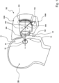
- Fig. 1 shows an embodiment of an examination apparatus 10 according to the present invention.
- examination apparatus 10 is associated with a patient 20 to be examined, but the position of apparatus 10 with respect to patient 20 does not correspond exactly to an operating condition; in fact, its mechanical assembly 1000, i.e. the internal frame and the external casing, is not in touch with the face of the patient but is distant about 1 cm (the same is true for Fig. 2 and Fig. 4 ).
- the mechanical assembly is arranged to contact a front side of a face of a patient under examination when the examination apparatus is in use; according to the embodiment of Fig. 1 , mechanical assembly 1000 is designed to contact at the top forehead 21 and at the bottom upper lip 22 (i.e. the region where the philtrum is located) and/or cheeks 23 on both sides of nose 24.
- the examination apparatus is head-mounted and the mechanical assembly 1000 is designed to contact not only a front side of a head of a patient, but also a top side and a back side (see e.g. Fig. 5 and Fig. 6 ).
- the examination apparatus may be resting on a table or on a floor through e.g. a base.
- the apparatus according to the present invention has two basic components: an optical assembly (labelled 100 in Fig. 1 ) and a dome device (labelled 200 in Fig. 1 ) for the visual field perimetry capabilities; typically and advantageously, there is only one optical assembly and only dome device.
- an optical assembly labelled 100 in Fig. 1
- a dome device labelled 200 in Fig. 1
- a mirror 500 is evident and a display 600 is omitted (but see Fig. 7 ) as the explanation of the blind spot capabilities follows. It is to be noted that the mirror is highly advantageous.
- Optical assembly 100 is fixed-focus (i.e. there are no auto-focus capabilities) and mounted (directly or indirectly) to mechanical assembly 1000; it is arranged to be located opposite to eye 25 of patient 20 under examination when examination apparatus 10 is in use.
- Dome device 200 is fixed-position and is mounted (directly or indirectly) to mechanical assembly 1000.
- Dome device 200 has a curved surface 210; for the sake of simplicity, curved surface 210 may be a spherical surface (more accurate shapes may be considered).
- Dome device 200 is associated to a plurality of light emitting devices 220 (only two devices are associated to the reference numeral in Fig.
- micro-LEDs that may be arranged similarly to a traditional "Goldmann perimeter"; specifically, light emitting devices 220 are arranged so to emit light from curved surface 210 towards optical assembly 100; according to an embodiment, curved surface 210 belongs to a curved plate having a plurality of holes wherein a corresponding plurality of light emitting devices are inserted typically from the back of the curved plate.
- Dome device 200 is arranged to be located behind optical assembly 100 at a fixed position (therefore also at a fixed distance) therefrom and coaxial thereto when examination apparatus 10 is in use.
- a front side of examination apparatus 10 is configured so that, when it is in use, a volume 300, that may be called “front volume”, is defined between the front side of the examination apparatus and the front side of a face of patient 20 under examination sufficient for housing spectacles of patient 20 (see in particular Fig. 3A and Fig. 3B ).
- Such examination apparatus is very compact and light; in fact, it may take the form of a head-mounted equipment (see the figures).
- the optical assembly may be very simple, for example it may correspond to a single lens or more preferably to a doublet (see in particular Fig. 7 ), still providing accurate examination results.
- this embodiment of the examination apparatus looks similar to a diving mask or, even more, to a virtual reality goggle, even if it has nothing to do with such apparatuses.
- a mechanical assembly 1000 with a closed shell 50 mechanical assembly 1000 is arranged to be located in front of the eyes 25R and 25L of a patient to be examined; shell 50 is hollow and houses typically only one integrated assembly 2000 (see in particular Fig. 5 ).
- Shell 50 has a front portion designed to contact a front side of a face of a patient.
- shell 50 is associated with a coupling element 55 (that may be made of a rigid or flexible material) surrounding the front portion of shell 50 and designed to avoid (or at least limit) that ambient light reaches the eyes of the patent under examination; coupling element 55 may be designed to contact or at least get very close to front side of a face of a patient.
- Mechanical assembly 1000 comprises a belt or band to secure examination assembly 10 to the head of a patient to be examined; in particular, the belt or band contacts the back of the head (see Fig. 5 and Fig. 6 ). Another belt or band may be provided contacting the top of the head (see Fig. 5 and Fig. 6 ).
- the examination apparatus is head-mounted and the mechanical assembly is designed to contact not only a front side of a head of a patient, but also a top side and a back side (see e.g. Fig. 5 and Fig. 6 ).
- the examination apparatus may be resting on a table or on a floor through e.g. a base.
- examination apparatus 10 may comprise an electric push-button (not shown in the figures) for patient feedback that may be electrically connected to the first electric and electronic circuitry so that feedback from the patient may be transferred to external computer.
- both the electric and electronic circuitry and the electric push-button are parts of the examination apparatus.
- a frustoconical (or approximately frustoconical) volume 400 is defined between optical assembly 100 at a first end thereof (close to the eye) and dome device 200 at a second end thereof (remote from the eye); such volume is used for transferring light signals typically from dome device 200 to optical assembly 100 and then through optical assembly 100 to eye 25 of patient 20 under examination.
- volume 400 may be cylindrical (or approximately cylindrical).
- Optical assembly 100 and dome device 200 are preferably parts of a same integrated assembly; an embodiment of such assembly is shown in Fig. 7 and labelled 2000.
- Assembly 2000 comprises a hollow assembly shell 2050 used for housing and mounting several components including optical assembly 100 and dome device 200.
- examination apparatus 10 comprises a hollow apparatus shell 50 for housing and mounting at least one assembly shell 2050.
- examination apparatus 10 comprises only one integrated assembly 2000; in this way, weight is reduced, cost is reduced and the integrated assembly may be a bit bigger (as there is not another integrated assembly adjacent thereto).
- integrated assembly 2000 may be relocated so to be opposite to a right eye 25R or to a left eye 25L of a patient 20 under examination;
- Fig. 6 shows a lever 2060 (to be acted upon manually) for relocating integrated assembly 2000 between eyes.
- a transversal position of optical assembly 100 may be adjusted so to align the assembly with pupil 26 of eye 25 of a patient 20 under examination.
- first examination apparatus 10 is mounted on the head of a patient 20 to be examined, and then such adjustment is made.
- Fig. 6 shows two knobs 2070 (to be acted upon manually) for carrying out adjustments respectively according to a first axis and to a second axis, the first axis and the second axis being perpendicular to each other and both perpendicular to the optical axis of optical assembly 100.
- the position of the whole integrated assembly 2000 may be adjusted; in fact, by moving integrated assembly 2000 also optical assembly 100 is correspondingly moved.
- the axial position of optical assembly 100 may be not adjusted; in other words, the solution according to the present invention as set out above does not require an axial adjustment of optical assembly 100. Specifically, with reference to the embodiment of the figures, the solution according to the present invention as set out above does not require an axial adjustment of integrated assembly 2000. Furthermore, considering integrated assembly 2000, the relative position of optical assembly 100 and dome device 200 is fixed and not adjustable.
- Examination apparatus 10 comprises an illumination device 230 arranged to illuminate curved surface 210 from a distance in a uniform manner.
- illumination device is typically a single LED; in order to obtain a uniform illumination with a single LED on a curved surface, the LED is not directed to the center of the curved surface but to a point located in a boundary region of the curved surface (see arrow in Fig. 7 ).
- the illumination device is highly advantageous but not strictly necessary for the present invention.
- illumination device 230 is located outside of internal volume 400 so to that light signals transferred from dome device 200 to optical assembly 100 do not hit illumination device 230.
- illumination device 230 is located laterally to internal volume 400; in particular, when examination apparatus 10 is in use, illumination device 230 is located above volume 400.
- optical assembly 100 is very simple and, in particular, comprises a lens 110 being a doublet (see Fig. 7 ) in order to compensate aberrations; it is to be noted that, in the field of optics, the term "lens" is often used to indicate a small set of associated lenses.
- the examination apparatus according to the present invention is arranged so that a distance between a front surface of optical assembly 100 and pupil 26 is in the range between 20 mm and 40 mm, preferably about 30 mm; in this way, the apparatus has a very compact size while at the same time this distance is sufficient for housing spectacles of a patient 20.
- curved surface 210 has a circular perimeter and has a diameter in the range between 55 mm and 80 mm, preferably about 65 mm; in this way, the apparatus has a very compact size.
- a distance between a lens 110 of optical assembly 100 and curved surface 210 corresponds (about) to a back focal length of a lens of optical assembly 100.
- a distance between a rear surface of optical assembly 100 and curved surface 210 is advantageously in the range between 55 mm and 75 mm, preferably about 65 mm; in this way, the apparatus has a very compact size.
- a distance between a lens 110 of optical assembly 100 and curved surface 210 is such as to create an image of curved surface 210 in the eye 25 of a patient 20 under examination as if curved surface 210 would be at (about) 30 cm from eye 25.
- a distance between a rear surface of optical assembly 100 and curved surface 210 is advantageously in the range between 45 mm and 65 mm, preferably about 55 mm; in this way, the apparatus has a very compact size.
- optical assembly 100 comprises a lens 110 having a focal distance in the range between 60 mm and 90 mm.
- examination apparatus 10 comprises a semi-transparent mirror 500 located between optical assembly 100 and dome device 200, specifically inside internal volume 400; light from optical assembly 100 is transmitted and light from dome device 200 is reflected.
- Mirror 500 is useful for carrying out one or more functions (in particular examinations) additional to visual field perimetry.
- semi-transparent mirror 500 is fixedly mounted to integrated assembly 2000.
- semi-transparent mirror 500 is preferably arranged so to fully exploit the surface of the lenses of spectacles of a patient 20 under examination; specifically, when the examination apparatus is in use, mirror 500 reflects downwardly light coming from optical assembly 100.
- semi-transparent mirror 500 is inclined of an angle with respect to an axis A of optical assembly 100; this angle is in the range from 30° to 60°, preferably about 45°.
- semi-transparent mirror 500 has a transmissivity in the range from 70% to 90% (preferably about 80%) and a reflectivity in the range from 30% to 10% (preferably about 20%) in the visible spectrum.
- semi-transparent mirror 500 has a transmissivity of about 0% and a reflectivity of about 100% in the IR spectrum.
- the examination apparatus 10 comprises an electronic display 600; display 600 is preferably an OLED display due to its high darkness when it is switched off; the images generated on this display are directed towards mirror 500, reflected by mirror 500, directed towards optical assembly 100, focused by optical assembly 100, and finally directed towards eye 25.
- Display 600 is useful for carrying out blind spot examinations and preferably furthermore for providing instructions and/or information to a patient 20 under examination. It is to be noted that the electronic display is advantageous but not strictly necessary for the present invention.
- electronic display 600 is located outside of internal volume 400 so to that light signals transferred from dome device 200 to optical assembly 100 do not hit electronic display 600.
- electronic display 600 is located laterally to internal volume 400; in particular, when examination apparatus 10 is in use, electronic display 600 is located below volume 400.
- electronic display 600 is fixedly mounted to integrated assembly 2000.
- examination apparatus 10 comprises a camera 700 for gaze tracking specifically outside of internal volume 400; camera 700 typically consists of a CMOS device and a lens; images of eye 25 coming from optical assembly 100 are directed towards mirror 500, reflected by mirror 500, directed towards camera 700.
- camera 700 is located outside of internal volume 400 so that light signals transferred from dome device 200 to optical assembly 100 do not hit camera 700.
- camera 700 is located laterally to internal volume 400; in particular, when examination apparatus 10 is in use, camera 700 is located below volume 400.
- camera 700 is fixedly mounted to integrated assembly 2000.
- examination apparatus 10 comprises IR illumination devices 120 (for example IR LEDs) arranged to illuminate pupil 26 of eye 25 of patient 20 under examination; in this case, camera 20 is an IR camera.
- Devices 120 may be associated to optical assembly 100 and may be arranged around a front lens of optical assembly 100.
- examination apparatus 10 comprises one fixation light source 810 for visual field perimetry examination.
- examination apparatus 10 may comprise other two fixation light sources for blind spot examination.
- fixation light sources are single LEDs.
- fixation light sources are associated to curved surface 210; in particular, each fixation light source may be inserted from the back of curved plate 210 into a corresponding hole of curved plate 210; fixation light source 810 should be in the center of curved plate 210 while fixation light sources for blind spot examination should be respectively a bit (e. g. 1 cm) to the right and bit (e. g. 1 cm) to the left.
Landscapes
- Life Sciences & Earth Sciences (AREA)
- Health & Medical Sciences (AREA)
- Medical Informatics (AREA)
- Biophysics (AREA)
- Ophthalmology & Optometry (AREA)
- Engineering & Computer Science (AREA)
- Biomedical Technology (AREA)
- Heart & Thoracic Surgery (AREA)
- Physics & Mathematics (AREA)
- Molecular Biology (AREA)
- Surgery (AREA)
- Animal Behavior & Ethology (AREA)
- General Health & Medical Sciences (AREA)
- Public Health (AREA)
- Veterinary Medicine (AREA)
- Eye Examination Apparatus (AREA)
Claims (14)
- Untersuchungsgerät (10) mit Gesichtsfeldperimetrie und Toter-Winkel-Funktionen, umfassend:- eine mechanische Baugruppe (1000), die so angeordnet ist, dass sie eine Vorderseite eines Gesichts eines zu untersuchenden Patienten (20) berührt, wenn das Untersuchungsgerät (10) in Gebrauch ist,- eine optische Baugruppe (100) mit festem Fokus, die an der mechanischen Baugruppe (1000) montiert und so angeordnet ist, dass sie sich gegenüber einem Auge (25) eines zu untersuchenden Patienten (20) befindet, wenn das Untersuchungsgerät (10) in Gebrauch ist,- eine ortsfeste Kuppelvorrichtung (200), die an der mechanischen Baugruppe (1000) montiert ist und eine gekrümmte Oberfläche (210) aufweist, die mit einer Vielzahl von lichtemittierenden Vorrichtungen (220) assoziiert ist, wobei die Kuppelvorrichtung (200) so angeordnet ist, dass sie sich hinter der optischen Baugruppe (100) an einer festen Position davon befindet und koaxial dazu ist, wenn das Untersuchungsgerät (10) in Gebrauch ist, und- eine Beleuchtungsvorrichtung (230), die angeordnet ist, um die gekrümmte Oberfläche (210) der Kuppelvorrichtung (200) gleichmäßig zu beleuchten,wobei eine Vorderseite des Untersuchungsgeräts (10) so konfiguriert ist, dass bei Gebrauch des Untersuchungsgeräts (10) ein Volumen (300) zwischen der Vorderseite des Untersuchungsgeräts (10) und einer Vorderseite eines Gesichts eines zu untersuchenden Patienten (20) definiert ist, das ausreicht, um eine Brille eines zu untersuchenden Patienten (20) aufzunehmen; wobei eine Querposition der optischen Baugruppe (100) so eingestellt werden kann, dass sie mit einer Pupille (26) eines Auges (25) eines zu untersuchenden Patienten (20) ausgerichtet wird;
gekennzeichnet durch- einen halbdurchlässigen Spiegel (500), der sich zwischen der optischen Baugruppe (100) und der Kuppelvorrichtung (200) befindet und angeordnet ist, um Licht von der Kuppelvorrichtung (200) zu der optischen Baugruppe (100) zu übertragen, und- eine elektronische Anzeige (600) zur Untersuchung des toten Winkels, die so angeordnet ist, dass die von ihr erzeugten Bilder durch Reflexion durch den halbdurchlässigen Spiegel (500) auf die optische Baugruppe (100) gerichtet sind. - Untersuchungsgerät (10) nach Anspruch 1, wobei die optische Baugruppe (100) und die Kuppelvorrichtung (200) Teile derselben integrierten Baugruppe (2000) sind.
- Untersuchungsgerät (10) nach Anspruch 2, wobei die integrierte Baugruppe (2000) einzigartig ist und so verlagert werden kann, dass sie einem rechten Auge (25R) oder einem linken Auge (25L) eines zu untersuchenden Patienten (20) gegenüberliegt.
- Untersuchungsgerät (10) nach Anspruch 1 oder 2 oder 3, wobei eine axiale Position der optischen Baugruppe (100) oder der integrierten Baugruppe (2000) nicht eingestellt werden kann.
- Untersuchungsgerät (10) nach einem der vorhergehenden Ansprüche, wobei die optische Baugruppe (100) eine Linse (110) umfasst, die ein Dublett ist.
- Untersuchungsgerät (10) nach einem der vorhergehenden Ansprüche, das so angeordnet ist, dass ein Abstand zwischen einer Vorderoberfläche der optischen Baugruppe (100) und einer Pupille (26) eines Auges (25) eines zu untersuchenden Patienten (20) im Bereich zwischen 20 mm und 40 mm, vorzugsweise etwa 30 mm, liegt.
- Untersuchungsgerät (10) nach einem der vorhergehenden Ansprüche, wobei die gekrümmte Oberfläche (210) einen kreisförmigen Umfang aufweist und einen Durchmesser im Bereich zwischen 55 mm und 80 mm, vorzugsweise etwa 65 mm, aufweist.
- Untersuchungsgerät (10) nach einem der vorhergehenden Ansprüche 1 bis 7, wobei ein Abstand zwischen einer Linse (110) der optischen Baugruppe (100) und der gekrümmten Oberfläche (210) einer hinteren Brennweite einer Linse der optischen Baugruppe (100) entspricht.
- Untersuchungsgerät (10) nach Anspruch 8, wobei ein Abstand zwischen einer Rückoberfläche der optischen Baugruppe (100) und der gekrümmten Oberfläche (210) im Bereich zwischen 55 mm und 75 mm, vorzugsweise etwa 65 mm, liegt.
- Untersuchungsgerät (10) nach einem der vorhergehenden Ansprüche 1 bis 7, wobei ein Abstand zwischen einer Linse (110) der optischen Baugruppe (100) und der gekrümmten Oberfläche (210) derart ist, dass ein Bild der gekrümmten Oberfläche (210) in dem Auge (25) eines zu untersuchenden Patienten (20) erzeugt wird, als ob die gekrümmte Oberfläche (210) 30 cm von dem Auge (25) entfernt wäre.
- Untersuchungsgerät (10) nach Anspruch 10, wobei ein Abstand zwischen einer Rückoberfläche der optischen Baugruppe (100) und der gekrümmten Oberfläche (210) im Bereich zwischen 45 mm und 65 mm, vorzugsweise etwa 55 mm, liegt.
- Untersuchungsgerät (10) nach einem der vorhergehenden Ansprüche, wobei die optische Baugruppe (100) eine Linse (110) mit einer Fokaldistanz im Bereich zwischen 60 mm und 90 mm umfasst.
- Untersuchungsgerät (10) nach einem der vorhergehenden Ansprüche, ferner umfassend eine Kamera (700) zur Blickverfolgung.
- Untersuchungsgerät (10) nach einem der vorhergehenden Ansprüche, ferner umfassend eine Fixierlichtquelle (810) zur Gesichtsfeldperimetrieuntersuchung.
Applications Claiming Priority (2)
| Application Number | Priority Date | Filing Date | Title |
|---|---|---|---|
| IT102020000001255A IT202000001255A1 (it) | 2020-01-23 | 2020-01-23 | Strumento compatto per l'esame perimetrico del campo visivo |
| PCT/IB2021/050505 WO2021149006A1 (en) | 2020-01-23 | 2021-01-22 | Compact examination apparatus with visual field perimetry and blind spot capabilities |
Publications (2)
| Publication Number | Publication Date |
|---|---|
| EP4093262A1 EP4093262A1 (de) | 2022-11-30 |
| EP4093262B1 true EP4093262B1 (de) | 2024-01-10 |
Family
ID=70155215
Family Applications (1)
| Application Number | Title | Priority Date | Filing Date |
|---|---|---|---|
| EP21701185.7A Active EP4093262B1 (de) | 2020-01-23 | 2021-01-22 | Kompaktes untersuchungsgerät mit gesichtsfeldperimetrie- und skotomfähigkeit |
Country Status (3)
| Country | Link |
|---|---|
| EP (1) | EP4093262B1 (de) |
| IT (1) | IT202000001255A1 (de) |
| WO (1) | WO2021149006A1 (de) |
Families Citing this family (2)
| Publication number | Priority date | Publication date | Assignee | Title |
|---|---|---|---|---|
| TWI824868B (zh) * | 2022-12-07 | 2023-12-01 | 張朝凱 | 視野範圍之檢測系統 |
| CN116939907B (zh) * | 2023-07-21 | 2026-03-27 | 维沃移动通信有限公司 | 灯带的驱动方法、装置、电子设备及可读存储介质 |
Family Cites Families (4)
| Publication number | Priority date | Publication date | Assignee | Title |
|---|---|---|---|---|
| DE69709709D1 (de) * | 1996-03-15 | 2002-02-21 | Retinal Display Cayman Ltd | Verfahren und vorrichtung zur betrachtung eines bildes |
| WO2016132804A1 (ja) * | 2015-02-17 | 2016-08-25 | ローム株式会社 | 視力検査装置および視力検査システム |
| DE102015217682A1 (de) * | 2015-09-16 | 2017-03-16 | Carl Zeiss Ag | Vorrichtung zur Augenuntersuchung |
| FR3065820B1 (fr) * | 2017-04-28 | 2021-09-17 | Essilor Int | Procede de determination d'un filtre de lumiere applique a un verre de lunettes ; dispositif d'affichage et casque de realite virtuelle associes |
-
2020
- 2020-01-23 IT IT102020000001255A patent/IT202000001255A1/it unknown
-
2021
- 2021-01-22 WO PCT/IB2021/050505 patent/WO2021149006A1/en not_active Ceased
- 2021-01-22 EP EP21701185.7A patent/EP4093262B1/de active Active
Also Published As
| Publication number | Publication date |
|---|---|
| WO2021149006A1 (en) | 2021-07-29 |
| IT202000001255A1 (it) | 2021-07-23 |
| EP4093262A1 (de) | 2022-11-30 |
Similar Documents
| Publication | Publication Date | Title |
|---|---|---|
| US11033184B2 (en) | Self-illuminated handheld lens for retinal examination and photography and related method thereof | |
| US10078226B2 (en) | Portable eye viewing device enabled for enhanced field of view | |
| EP0346846A1 (de) | Augenbewegungsinspektionsgerät | |
| US9392938B2 (en) | Ophthalmoscope | |
| US5163420A (en) | Headlight system | |
| US7553020B2 (en) | Medical diagnostic instrument with variable focus liquid lens | |
| US20080309586A1 (en) | Viewing System for Augmented Reality Head Mounted Display | |
| US9513479B2 (en) | Virtual image display apparatus | |
| WO1999020172A1 (en) | Portable fundus viewing system for an undilated eye | |
| KR20180113449A (ko) | 헤드 마운트 디스플레이 장치 | |
| JP2008512217A (ja) | 可撓ビデオ内視鏡延長具および方法 | |
| US10426340B2 (en) | Self-illuminated handheld lens for retinal examination and photography and related method thereof | |
| EP4093262A1 (de) | Kompaktes untersuchungsgerät mit gesichtsfeldperimetrie- und skotomfähigkeit | |
| EP2912993B1 (de) | Lichtquellenvorrichtung für Endoskopsystem | |
| CN110811542A (zh) | 眼底相机 | |
| JP2010063485A (ja) | 内視鏡用照明光学系及び内視鏡 | |
| CN107468208B (zh) | 一种便携式眼部诊断专用成像系统 | |
| JP2022142763A (ja) | 時計職人用ルーペ | |
| US20250331711A1 (en) | Optical system for visual field testing | |
| JP3761834B2 (ja) | 画像表示装置 | |
| JP2003315725A (ja) | 画像表示装置 | |
| US5652639A (en) | Indirect ophthalmoscope producing an erect stereoscopic image | |
| US20160242643A1 (en) | Transparent Camera for Imaging the Eye | |
| KR20230070931A (ko) | 망막상 관찰을 위한 안저카메라 및 이를 이용하는 조명 및 이미지 처리방법 | |
| JP2021023542A (ja) | 眼科装置 |
Legal Events
| Date | Code | Title | Description |
|---|---|---|---|
| STAA | Information on the status of an ep patent application or granted ep patent |
Free format text: STATUS: UNKNOWN |
|
| STAA | Information on the status of an ep patent application or granted ep patent |
Free format text: STATUS: THE INTERNATIONAL PUBLICATION HAS BEEN MADE |
|
| PUAI | Public reference made under article 153(3) epc to a published international application that has entered the european phase |
Free format text: ORIGINAL CODE: 0009012 |
|
| STAA | Information on the status of an ep patent application or granted ep patent |
Free format text: STATUS: REQUEST FOR EXAMINATION WAS MADE |
|
| 17P | Request for examination filed |
Effective date: 20220721 |
|
| AK | Designated contracting states |
Kind code of ref document: A1 Designated state(s): AL AT BE BG CH CY CZ DE DK EE ES FI FR GB GR HR HU IE IS IT LI LT LU LV MC MK MT NL NO PL PT RO RS SE SI SK SM TR |
|
| DAV | Request for validation of the european patent (deleted) | ||
| DAX | Request for extension of the european patent (deleted) | ||
| P01 | Opt-out of the competence of the unified patent court (upc) registered |
Effective date: 20230519 |
|
| GRAP | Despatch of communication of intention to grant a patent |
Free format text: ORIGINAL CODE: EPIDOSNIGR1 |
|
| STAA | Information on the status of an ep patent application or granted ep patent |
Free format text: STATUS: GRANT OF PATENT IS INTENDED |
|
| RIN1 | Information on inventor provided before grant (corrected) |
Inventor name: SCATTOLIN, NIKITA Inventor name: PETTINELLO, CRISTIANO Inventor name: PAJARO, RONNYE Inventor name: MINOZZI, MATTIA Inventor name: DE GIUSTI, ANDREA Inventor name: CODOGNO, NICOLA Inventor name: CARRARO, FEDERICO Inventor name: TANASSI, CESARE Inventor name: PASCOLINI, MICHELE |
|
| INTG | Intention to grant announced |
Effective date: 20230925 |
|
| GRAS | Grant fee paid |
Free format text: ORIGINAL CODE: EPIDOSNIGR3 |
|
| GRAA | (expected) grant |
Free format text: ORIGINAL CODE: 0009210 |
|
| STAA | Information on the status of an ep patent application or granted ep patent |
Free format text: STATUS: THE PATENT HAS BEEN GRANTED |
|
| AK | Designated contracting states |
Kind code of ref document: B1 Designated state(s): AL AT BE BG CH CY CZ DE DK EE ES FI FR GB GR HR HU IE IS IT LI LT LU LV MC MK MT NL NO PL PT RO RS SE SI SK SM TR |
|
| REG | Reference to a national code |
Ref country code: GB Ref legal event code: FG4D |
|
| REG | Reference to a national code |
Ref country code: CH Ref legal event code: EP |
|
| REG | Reference to a national code |
Ref country code: DE Ref legal event code: R096 Ref document number: 602021008523 Country of ref document: DE |
|
| REG | Reference to a national code |
Ref country code: IE Ref legal event code: FG4D |
|
| REG | Reference to a national code |
Ref country code: LT Ref legal event code: MG9D |
|
| REG | Reference to a national code |
Ref country code: NL Ref legal event code: MP Effective date: 20240110 |
|
| REG | Reference to a national code |
Ref country code: AT Ref legal event code: MK05 Ref document number: 1648201 Country of ref document: AT Kind code of ref document: T Effective date: 20240110 |
|
| PG25 | Lapsed in a contracting state [announced via postgrant information from national office to epo] |
Ref country code: NL Free format text: LAPSE BECAUSE OF FAILURE TO SUBMIT A TRANSLATION OF THE DESCRIPTION OR TO PAY THE FEE WITHIN THE PRESCRIBED TIME-LIMIT Effective date: 20240110 |
|
| PG25 | Lapsed in a contracting state [announced via postgrant information from national office to epo] |
Ref country code: NL Free format text: LAPSE BECAUSE OF FAILURE TO SUBMIT A TRANSLATION OF THE DESCRIPTION OR TO PAY THE FEE WITHIN THE PRESCRIBED TIME-LIMIT Effective date: 20240110 |
|
| PG25 | Lapsed in a contracting state [announced via postgrant information from national office to epo] |
Ref country code: IS Free format text: LAPSE BECAUSE OF FAILURE TO SUBMIT A TRANSLATION OF THE DESCRIPTION OR TO PAY THE FEE WITHIN THE PRESCRIBED TIME-LIMIT Effective date: 20240510 |
|
| PG25 | Lapsed in a contracting state [announced via postgrant information from national office to epo] |
Ref country code: LT Free format text: LAPSE BECAUSE OF FAILURE TO SUBMIT A TRANSLATION OF THE DESCRIPTION OR TO PAY THE FEE WITHIN THE PRESCRIBED TIME-LIMIT Effective date: 20240110 |
|
| PG25 | Lapsed in a contracting state [announced via postgrant information from national office to epo] |
Ref country code: GR Free format text: LAPSE BECAUSE OF FAILURE TO SUBMIT A TRANSLATION OF THE DESCRIPTION OR TO PAY THE FEE WITHIN THE PRESCRIBED TIME-LIMIT Effective date: 20240411 |
|
| PG25 | Lapsed in a contracting state [announced via postgrant information from national office to epo] |
Ref country code: HR Free format text: LAPSE BECAUSE OF FAILURE TO SUBMIT A TRANSLATION OF THE DESCRIPTION OR TO PAY THE FEE WITHIN THE PRESCRIBED TIME-LIMIT Effective date: 20240110 Ref country code: RS Free format text: LAPSE BECAUSE OF FAILURE TO SUBMIT A TRANSLATION OF THE DESCRIPTION OR TO PAY THE FEE WITHIN THE PRESCRIBED TIME-LIMIT Effective date: 20240410 |
|
| PG25 | Lapsed in a contracting state [announced via postgrant information from national office to epo] |
Ref country code: ES Free format text: LAPSE BECAUSE OF FAILURE TO SUBMIT A TRANSLATION OF THE DESCRIPTION OR TO PAY THE FEE WITHIN THE PRESCRIBED TIME-LIMIT Effective date: 20240110 |
|
| PG25 | Lapsed in a contracting state [announced via postgrant information from national office to epo] |
Ref country code: AT Free format text: LAPSE BECAUSE OF FAILURE TO SUBMIT A TRANSLATION OF THE DESCRIPTION OR TO PAY THE FEE WITHIN THE PRESCRIBED TIME-LIMIT Effective date: 20240110 |
|
| PG25 | Lapsed in a contracting state [announced via postgrant information from national office to epo] |
Ref country code: RS Free format text: LAPSE BECAUSE OF FAILURE TO SUBMIT A TRANSLATION OF THE DESCRIPTION OR TO PAY THE FEE WITHIN THE PRESCRIBED TIME-LIMIT Effective date: 20240410 Ref country code: NO Free format text: LAPSE BECAUSE OF FAILURE TO SUBMIT A TRANSLATION OF THE DESCRIPTION OR TO PAY THE FEE WITHIN THE PRESCRIBED TIME-LIMIT Effective date: 20240410 Ref country code: LT Free format text: LAPSE BECAUSE OF FAILURE TO SUBMIT A TRANSLATION OF THE DESCRIPTION OR TO PAY THE FEE WITHIN THE PRESCRIBED TIME-LIMIT Effective date: 20240110 Ref country code: IS Free format text: LAPSE BECAUSE OF FAILURE TO SUBMIT A TRANSLATION OF THE DESCRIPTION OR TO PAY THE FEE WITHIN THE PRESCRIBED TIME-LIMIT Effective date: 20240510 Ref country code: HR Free format text: LAPSE BECAUSE OF FAILURE TO SUBMIT A TRANSLATION OF THE DESCRIPTION OR TO PAY THE FEE WITHIN THE PRESCRIBED TIME-LIMIT Effective date: 20240110 Ref country code: GR Free format text: LAPSE BECAUSE OF FAILURE TO SUBMIT A TRANSLATION OF THE DESCRIPTION OR TO PAY THE FEE WITHIN THE PRESCRIBED TIME-LIMIT Effective date: 20240411 Ref country code: ES Free format text: LAPSE BECAUSE OF FAILURE TO SUBMIT A TRANSLATION OF THE DESCRIPTION OR TO PAY THE FEE WITHIN THE PRESCRIBED TIME-LIMIT Effective date: 20240110 Ref country code: BG Free format text: LAPSE BECAUSE OF FAILURE TO SUBMIT A TRANSLATION OF THE DESCRIPTION OR TO PAY THE FEE WITHIN THE PRESCRIBED TIME-LIMIT Effective date: 20240110 Ref country code: AT Free format text: LAPSE BECAUSE OF FAILURE TO SUBMIT A TRANSLATION OF THE DESCRIPTION OR TO PAY THE FEE WITHIN THE PRESCRIBED TIME-LIMIT Effective date: 20240110 |
|
| PG25 | Lapsed in a contracting state [announced via postgrant information from national office to epo] |
Ref country code: PL Free format text: LAPSE BECAUSE OF FAILURE TO SUBMIT A TRANSLATION OF THE DESCRIPTION OR TO PAY THE FEE WITHIN THE PRESCRIBED TIME-LIMIT Effective date: 20240110 Ref country code: PT Free format text: LAPSE BECAUSE OF FAILURE TO SUBMIT A TRANSLATION OF THE DESCRIPTION OR TO PAY THE FEE WITHIN THE PRESCRIBED TIME-LIMIT Effective date: 20240510 |
|
| PG25 | Lapsed in a contracting state [announced via postgrant information from national office to epo] |
Ref country code: SE Free format text: LAPSE BECAUSE OF FAILURE TO SUBMIT A TRANSLATION OF THE DESCRIPTION OR TO PAY THE FEE WITHIN THE PRESCRIBED TIME-LIMIT Effective date: 20240110 Ref country code: PT Free format text: LAPSE BECAUSE OF FAILURE TO SUBMIT A TRANSLATION OF THE DESCRIPTION OR TO PAY THE FEE WITHIN THE PRESCRIBED TIME-LIMIT Effective date: 20240510 Ref country code: PL Free format text: LAPSE BECAUSE OF FAILURE TO SUBMIT A TRANSLATION OF THE DESCRIPTION OR TO PAY THE FEE WITHIN THE PRESCRIBED TIME-LIMIT Effective date: 20240110 Ref country code: LV Free format text: LAPSE BECAUSE OF FAILURE TO SUBMIT A TRANSLATION OF THE DESCRIPTION OR TO PAY THE FEE WITHIN THE PRESCRIBED TIME-LIMIT Effective date: 20240110 |
|
| REG | Reference to a national code |
Ref country code: CH Ref legal event code: PL |
|
| PG25 | Lapsed in a contracting state [announced via postgrant information from national office to epo] |
Ref country code: LU Free format text: LAPSE BECAUSE OF NON-PAYMENT OF DUE FEES Effective date: 20240122 |
|
| PG25 | Lapsed in a contracting state [announced via postgrant information from national office to epo] |
Ref country code: LU Free format text: LAPSE BECAUSE OF NON-PAYMENT OF DUE FEES Effective date: 20240122 |
|
| PG25 | Lapsed in a contracting state [announced via postgrant information from national office to epo] |
Ref country code: DK Free format text: LAPSE BECAUSE OF FAILURE TO SUBMIT A TRANSLATION OF THE DESCRIPTION OR TO PAY THE FEE WITHIN THE PRESCRIBED TIME-LIMIT Effective date: 20240110 |
|
| REG | Reference to a national code |
Ref country code: DE Ref legal event code: R097 Ref document number: 602021008523 Country of ref document: DE |
|
| PG25 | Lapsed in a contracting state [announced via postgrant information from national office to epo] |
Ref country code: SM Free format text: LAPSE BECAUSE OF FAILURE TO SUBMIT A TRANSLATION OF THE DESCRIPTION OR TO PAY THE FEE WITHIN THE PRESCRIBED TIME-LIMIT Effective date: 20240110 |
|
| PG25 | Lapsed in a contracting state [announced via postgrant information from national office to epo] |
Ref country code: BE Free format text: LAPSE BECAUSE OF NON-PAYMENT OF DUE FEES Effective date: 20240131 |
|
| PG25 | Lapsed in a contracting state [announced via postgrant information from national office to epo] |
Ref country code: CH Free format text: LAPSE BECAUSE OF NON-PAYMENT OF DUE FEES Effective date: 20240131 |
|
| PG25 | Lapsed in a contracting state [announced via postgrant information from national office to epo] |
Ref country code: EE Free format text: LAPSE BECAUSE OF FAILURE TO SUBMIT A TRANSLATION OF THE DESCRIPTION OR TO PAY THE FEE WITHIN THE PRESCRIBED TIME-LIMIT Effective date: 20240110 Ref country code: CZ Free format text: LAPSE BECAUSE OF FAILURE TO SUBMIT A TRANSLATION OF THE DESCRIPTION OR TO PAY THE FEE WITHIN THE PRESCRIBED TIME-LIMIT Effective date: 20240110 |
|
| PG25 | Lapsed in a contracting state [announced via postgrant information from national office to epo] |
Ref country code: SK Free format text: LAPSE BECAUSE OF FAILURE TO SUBMIT A TRANSLATION OF THE DESCRIPTION OR TO PAY THE FEE WITHIN THE PRESCRIBED TIME-LIMIT Effective date: 20240110 |
|
| PG25 | Lapsed in a contracting state [announced via postgrant information from national office to epo] |
Ref country code: SM Free format text: LAPSE BECAUSE OF FAILURE TO SUBMIT A TRANSLATION OF THE DESCRIPTION OR TO PAY THE FEE WITHIN THE PRESCRIBED TIME-LIMIT Effective date: 20240110 Ref country code: SK Free format text: LAPSE BECAUSE OF FAILURE TO SUBMIT A TRANSLATION OF THE DESCRIPTION OR TO PAY THE FEE WITHIN THE PRESCRIBED TIME-LIMIT Effective date: 20240110 Ref country code: RO Free format text: LAPSE BECAUSE OF FAILURE TO SUBMIT A TRANSLATION OF THE DESCRIPTION OR TO PAY THE FEE WITHIN THE PRESCRIBED TIME-LIMIT Effective date: 20240110 Ref country code: EE Free format text: LAPSE BECAUSE OF FAILURE TO SUBMIT A TRANSLATION OF THE DESCRIPTION OR TO PAY THE FEE WITHIN THE PRESCRIBED TIME-LIMIT Effective date: 20240110 Ref country code: DK Free format text: LAPSE BECAUSE OF FAILURE TO SUBMIT A TRANSLATION OF THE DESCRIPTION OR TO PAY THE FEE WITHIN THE PRESCRIBED TIME-LIMIT Effective date: 20240110 Ref country code: CZ Free format text: LAPSE BECAUSE OF FAILURE TO SUBMIT A TRANSLATION OF THE DESCRIPTION OR TO PAY THE FEE WITHIN THE PRESCRIBED TIME-LIMIT Effective date: 20240110 Ref country code: CH Free format text: LAPSE BECAUSE OF NON-PAYMENT OF DUE FEES Effective date: 20240131 Ref country code: BE Free format text: LAPSE BECAUSE OF NON-PAYMENT OF DUE FEES Effective date: 20240131 |
|
| REG | Reference to a national code |
Ref country code: BE Ref legal event code: MM Effective date: 20240131 |
|
| PG25 | Lapsed in a contracting state [announced via postgrant information from national office to epo] |
Ref country code: MC Free format text: LAPSE BECAUSE OF FAILURE TO SUBMIT A TRANSLATION OF THE DESCRIPTION OR TO PAY THE FEE WITHIN THE PRESCRIBED TIME-LIMIT Effective date: 20240110 |
|
| PLBE | No opposition filed within time limit |
Free format text: ORIGINAL CODE: 0009261 |
|
| STAA | Information on the status of an ep patent application or granted ep patent |
Free format text: STATUS: NO OPPOSITION FILED WITHIN TIME LIMIT |
|
| PG25 | Lapsed in a contracting state [announced via postgrant information from national office to epo] |
Ref country code: MC Free format text: LAPSE BECAUSE OF FAILURE TO SUBMIT A TRANSLATION OF THE DESCRIPTION OR TO PAY THE FEE WITHIN THE PRESCRIBED TIME-LIMIT Effective date: 20240110 |
|
| 26N | No opposition filed |
Effective date: 20241011 |
|
| PG25 | Lapsed in a contracting state [announced via postgrant information from national office to epo] |
Ref country code: FR Free format text: LAPSE BECAUSE OF NON-PAYMENT OF DUE FEES Effective date: 20240310 |
|
| PG25 | Lapsed in a contracting state [announced via postgrant information from national office to epo] |
Ref country code: IE Free format text: LAPSE BECAUSE OF NON-PAYMENT OF DUE FEES Effective date: 20240122 |
|
| PG25 | Lapsed in a contracting state [announced via postgrant information from national office to epo] |
Ref country code: IE Free format text: LAPSE BECAUSE OF NON-PAYMENT OF DUE FEES Effective date: 20240122 Ref country code: FR Free format text: LAPSE BECAUSE OF NON-PAYMENT OF DUE FEES Effective date: 20240310 |
|
| PG25 | Lapsed in a contracting state [announced via postgrant information from national office to epo] |
Ref country code: SI Free format text: LAPSE BECAUSE OF FAILURE TO SUBMIT A TRANSLATION OF THE DESCRIPTION OR TO PAY THE FEE WITHIN THE PRESCRIBED TIME-LIMIT Effective date: 20240110 |
|
| PG25 | Lapsed in a contracting state [announced via postgrant information from national office to epo] |
Ref country code: CY Free format text: LAPSE BECAUSE OF FAILURE TO SUBMIT A TRANSLATION OF THE DESCRIPTION OR TO PAY THE FEE WITHIN THE PRESCRIBED TIME-LIMIT; INVALID AB INITIO Effective date: 20210122 |
|
| PG25 | Lapsed in a contracting state [announced via postgrant information from national office to epo] |
Ref country code: HU Free format text: LAPSE BECAUSE OF FAILURE TO SUBMIT A TRANSLATION OF THE DESCRIPTION OR TO PAY THE FEE WITHIN THE PRESCRIBED TIME-LIMIT; INVALID AB INITIO Effective date: 20210122 |
|
| GBPC | Gb: european patent ceased through non-payment of renewal fee |
Effective date: 20250122 |
|
| PG25 | Lapsed in a contracting state [announced via postgrant information from national office to epo] |
Ref country code: FI Free format text: LAPSE BECAUSE OF FAILURE TO SUBMIT A TRANSLATION OF THE DESCRIPTION OR TO PAY THE FEE WITHIN THE PRESCRIBED TIME-LIMIT Effective date: 20240110 |
|
| PG25 | Lapsed in a contracting state [announced via postgrant information from national office to epo] |
Ref country code: GB Free format text: LAPSE BECAUSE OF NON-PAYMENT OF DUE FEES Effective date: 20250122 |
|
| PG25 | Lapsed in a contracting state [announced via postgrant information from national office to epo] |
Ref country code: TR Free format text: LAPSE BECAUSE OF FAILURE TO SUBMIT A TRANSLATION OF THE DESCRIPTION OR TO PAY THE FEE WITHIN THE PRESCRIBED TIME-LIMIT Effective date: 20240110 |
|
| PGFP | Annual fee paid to national office [announced via postgrant information from national office to epo] |
Ref country code: DE Payment date: 20251203 Year of fee payment: 6 |
|
| PGFP | Annual fee paid to national office [announced via postgrant information from national office to epo] |
Ref country code: IT Payment date: 20251219 Year of fee payment: 6 |