EP4093071A1 - Audio transmission method and electronic device - Google Patents
Audio transmission method and electronic device Download PDFInfo
- Publication number
- EP4093071A1 EP4093071A1 EP21771311.4A EP21771311A EP4093071A1 EP 4093071 A1 EP4093071 A1 EP 4093071A1 EP 21771311 A EP21771311 A EP 21771311A EP 4093071 A1 EP4093071 A1 EP 4093071A1
- Authority
- EP
- European Patent Office
- Prior art keywords
- radio frequency
- electronic device
- sub
- frequency signal
- audio
- Prior art date
- Legal status (The legal status is an assumption and is not a legal conclusion. Google has not performed a legal analysis and makes no representation as to the accuracy of the status listed.)
- Pending
Links
Images

Classifications
-
- H—ELECTRICITY
- H04—ELECTRIC COMMUNICATION TECHNIQUE
- H04B—TRANSMISSION
- H04B1/00—Details of transmission systems, not covered by a single one of groups H04B3/00 - H04B13/00; Details of transmission systems not characterised by the medium used for transmission
- H04B1/005—Details of transmission systems, not covered by a single one of groups H04B3/00 - H04B13/00; Details of transmission systems not characterised by the medium used for transmission adapting radio receivers, transmitters andtransceivers for operation on two or more bands, i.e. frequency ranges
-
- H—ELECTRICITY
- H04—ELECTRIC COMMUNICATION TECHNIQUE
- H04W—WIRELESS COMMUNICATION NETWORKS
- H04W4/00—Services specially adapted for wireless communication networks; Facilities therefor
- H04W4/80—Services using short range communication, e.g. near-field communication [NFC], radio-frequency identification [RFID] or low energy communication
-
- H—ELECTRICITY
- H04—ELECTRIC COMMUNICATION TECHNIQUE
- H04B—TRANSMISSION
- H04B1/00—Details of transmission systems, not covered by a single one of groups H04B3/00 - H04B13/00; Details of transmission systems not characterised by the medium used for transmission
- H04B1/06—Receivers
- H04B1/16—Circuits
- H04B1/1646—Circuits adapted for the reception of stereophonic signals
-
- H—ELECTRICITY
- H04—ELECTRIC COMMUNICATION TECHNIQUE
- H04B—TRANSMISSION
- H04B1/00—Details of transmission systems, not covered by a single one of groups H04B3/00 - H04B13/00; Details of transmission systems not characterised by the medium used for transmission
- H04B1/005—Details of transmission systems, not covered by a single one of groups H04B3/00 - H04B13/00; Details of transmission systems not characterised by the medium used for transmission adapting radio receivers, transmitters andtransceivers for operation on two or more bands, i.e. frequency ranges
- H04B1/0067—Details of transmission systems, not covered by a single one of groups H04B3/00 - H04B13/00; Details of transmission systems not characterised by the medium used for transmission adapting radio receivers, transmitters andtransceivers for operation on two or more bands, i.e. frequency ranges with one or more circuit blocks in common for different bands
-
- H—ELECTRICITY
- H04—ELECTRIC COMMUNICATION TECHNIQUE
- H04L—TRANSMISSION OF DIGITAL INFORMATION, e.g. TELEGRAPHIC COMMUNICATION
- H04L27/00—Modulated-carrier systems
- H04L27/10—Frequency-modulated carrier systems, i.e. using frequency-shift keying
- H04L27/16—Frequency regulation arrangements
-
- H—ELECTRICITY
- H04—ELECTRIC COMMUNICATION TECHNIQUE
- H04W—WIRELESS COMMUNICATION NETWORKS
- H04W76/00—Connection management
- H04W76/10—Connection setup
- H04W76/14—Direct-mode setup
-
- H—ELECTRICITY
- H04—ELECTRIC COMMUNICATION TECHNIQUE
- H04L—TRANSMISSION OF DIGITAL INFORMATION, e.g. TELEGRAPHIC COMMUNICATION
- H04L27/00—Modulated-carrier systems
- H04L27/10—Frequency-modulated carrier systems, i.e. using frequency-shift keying
Definitions
- the present invention relates to the field of communication technologies, and in particular, to an audio transmission method and an electronic device.
- the radio transmission technology of the audio (for example, the Bluetooth transmission technology) is applied more and more widely in wireless communications.
- audio streams are usually transmitted to different wireless devices at different times. In this way, utilization of the wireless transmission frequency band is low, resulting in a low wireless transmission rate of audio data.
- Embodiments of the present invention provide an audio transmission method and an electronic device, so as to solve the problem that when the existing electronic device transmits audio to a plurality of wireless devices, utilization of the wireless transmission frequency band is low, resulting in a low wireless transmission rate of audio data.
- an embodiment of the present invention provides an audio transmission method, applied to a first electronic device, and the audio transmission method includes:
- an embodiment of the present invention further provides an electronic device, where the electronic device is a first electronic device and includes:
- an embodiment of the present invention further provides an electronic device, including a processor, a memory, and a computer program stored in the memory and executable on the processor, and when the computer program is executed by the processor, steps of the audio transmission method according to the first aspect are implemented.
- an embodiment of the present invention further provides a computer-readable storage medium, where the computer-readable storage medium stores a computer program, and when the computer program is executed by a processor, steps of the audio transmission method according to the first aspect are implemented.
- an audio signal transmitted to the second electronic device is modulated into at least two target radio frequency signals; and the at least two target radio frequency signals are combined in a first slot, and a combined radio frequency signal is output to the second electronic device, where frequency bands of the at least two target radio frequency signals in the first slot are different.
- the first electronic device can realize concurrency of a plurality of radio frequency signals in a same slot, thereby improving frequency band utilization and a data transmission rate of the first electronic device.
- FIG. 1 is a flowchart of an audio transmission method according to an embodiment of the present invention.
- the audio transmission method is applied to a first electronic device, and the first electronic device is connected to a second electronic device through wireless connections, such as a Bluetooth connection.
- wireless connections such as a Bluetooth connection.
- the first electronic device and the second electronic device are not specified.
- the first electronic device may be the second electronic device, and the second electronic device may also be used as the first electronic device.
- the audio transmission method includes following steps.
- Step 101 Modulate, when the first electronic device transmits audio to a second electronic device, an audio signal transmitted to the second electronic device into at least two target radio frequency signals.
- the first electronic device and the second electronic device are connected through Bluetooth.
- an audio signal transmitted to the second electronic device is modulated into target radio frequency signals, where frequency bands of the at least two target radio frequency signals are different from each other.
- the audio transmitted from the first electronic device to the second electronic device can be transmitted through at least two target radio frequency signals, which expands the transmission channel in the audio transmission process, thereby improving the transmission rate.
- the manner and principle of modulating the audio signal into the radio frequency signal by the first electronic device may be referred to the related art. Details are not described herein again in this embodiment of the present invention.
- Step 102 Combine the at least two target radio frequency signals in a first slot, and output a combined radio frequency signal to the second electronic device.
- the at least two target radio frequency signals in the first slot may occupy at least two different frequency bands in the first slot, thus expanding the transmission channel of audio transmission.
- the audio transmission of Bluetooth is taken as an example.
- the FHSS Frequency-Hopping Spread Spectrum
- the Bluetooth transmission process only one of the channel frequency bands is used in each slot for communication, and the electronic device can only use different slots to send audio streams to the Bluetooth device, resulting in a relatively low audio transmission rate.
- At least two target radio frequency signals transmitted to the second electronic device can be modulated to different frequency bands in a same slot.
- utilization of frequency bands in a same slot is improved, so that in each slot, there are at least two or more information flows concurrently in different frequency bands.
- the second electronic device includes a first sub-device and a second sub-device.
- the step 101 includes:
- the audio transmitted from the first electronic device to the first sub-device and the audio transmitted from the first electronic device to the second sub-device may be a same piece of audio, or may be different pieces of audio.
- the first electronic device is separately connected to the first sub-device and the second sub-device via Bluetooth.
- the audio signal transmitted to the first sub-device is modulated into a first radio frequency signal
- the audio signal transmitted to the second sub-device is modulated into a second radio frequency signal
- a frequency band of the first radio frequency signal is different from a frequency band of the second radio frequency signal in the first slot.
- the radio frequency signal transmitted from the first electronic device to the first sub-device and the radio frequency signal transmitted from the first electronic device to the second sub-device are transmitted through different frequency bands in the same slot without overlapping, which improves the frequency band utilization in the same slot, and can also improve the transmission rate.
- first electronic device may respectively send three first radio frequency signals to the three first sub-devices, and the three first radio frequency signals are corresponding to different frequency bands in a same slot, to avoid overlapping of information flows of different devices in the same slot, thereby improving the frequency band utilization in the same slot.
- a quantity of the second radio frequency signals is consistent with a quantity of the second sub-devices, and each of the second radio frequency signals has a different frequency band in the first slot.
- the first radio frequency signal transmitted from the first electronic device to the first sub-device (the black square box in FIG. 2 ) and the second radio frequency signal (the white square box in FIG. 2 ) transmitted from the first electronic device to the second sub-device are modulated in different frequency bands, and in different slots, both the first radio frequency signal and the second radio frequency signal are corresponding to different frequency bands, thereby improving the frequency band utilization in the same slot.
- the first electronic device After the first electronic device modulates the first radio frequency signal and the second radio frequency signal to different frequency bands in the first slot, the first radio frequency signal and the second radio frequency signal are combined by a combiner in the first slot, and then the combined radio frequency signal is output to the first sub-device and the second sub-device. In this way, the first electronic device can communicate with different devices in a same slot, thereby improving frequency band utilization of the first electronic device.
- the second electronic device is an earphone
- the first sub-device is a left earphone of the earphone
- the second sub-device is a right earphone of the earphone
- the first radio frequency signal is a left-channel radio frequency signal
- the second radio frequency signal is a right-channel radio frequency signal.
- the first electronic device may be an electronic device that can output an audio signal to an earphone, such as a mobile phone, a tablet computer, and the like.
- the first electronic device is a mobile phone
- Bluetooth and WIFI in the mobile phone coexist in a time-division manner.
- an antenna is used to transmit a WIFI signal
- the antenna is used to transmit a Bluetooth signal.
- the mobile phone When the mobile phone separately establishes a Bluetooth connection with the left earphone and the right earphone, and is used to transmit an audio signal to the left earphone and the right earphone, the mobile phone can separately modulate a left-channel radio frequency signal transmitted to the left earphone and a right-channel radio frequency signal transmitted to the right earphone to different frequency bands in a same slot, so that the mobile phone can simultaneously send a signal to the left earphone and the right earphone by using different frequency bands in the same slot.
- the solution provided in the embodiments of the present invention improves frequency band utilization, thereby improving a data transmission rate, and a data throughput rate of the mobile phone for the left earphone and the right earphone.
- an audio signal transmitted to the second electronic device is modulated into at least two target radio frequency signals; and the at least two target radio frequency signals are combined in a first slot, and a combined radio frequency signal is output to the second electronic device, where frequency bands of the at least two target radio frequency signals in the first slot are different.
- the first electronic device can realize concurrency of a plurality of radio frequency signals in a same slot, thereby improving frequency band utilization and a data transmission rate of the first electronic device.
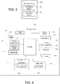
- FIG. 3 is a structural diagram of an electronic device according to an embodiment of the present invention.
- the electronic device is a first electronic device, and as shown in FIG. 3 , the electronic device 300 includes:
- the second electronic device includes a first sub-device and a second sub-device
- the modulation module is further configured to:
- a quantity of first radio frequency signals is consistent with a quantity of the first sub-devices, and each of the first radio frequency signals has a different frequency band in the first slot.
- the second electronic device is an earphone
- the first sub-device is a left earphone of the earphone
- the second sub-device is a right earphone of the earphone
- the first radio frequency signal is a left-channel radio frequency signal
- the second radio frequency signal is a right-channel radio frequency signal.
- the electronic device 300 can implement processes of the audio transmission method embodiment shown in FIG. 1 and achieve a same technical effect. To avoid repetition, details are not described herein again.
- an audio signal transmitted to the second electronic device is modulated into at least two target radio frequency signals; and the at least two target radio frequency signals are combined in a first slot, and a combined radio frequency signal is output to the second electronic device, where frequency bands of the at least two target radio frequency signals in the first slot are different.
- the electronic device 300 can realize concurrency of a plurality of radio frequency signals in a same slot, thereby improving frequency band utilization and a data transmission rate of the electronic device 300.
- FIG. 4 is a structural diagram of another electronic device for implementing an embodiment of the present invention.
- the electronic device 400 can implement processes of the audio transmission method embodiment shown in FIG. 1 and achieve a same technical effect.
- the electronic device 400 includes but is not limited to: a radio frequency unit 401, a network module 402, an audio output unit 403, an input unit 404, a sensor 405, a display unit 406, a user input unit 407, an interface unit 408, a memory 409, a processor 410, a power supply 411, and other components.
- a radio frequency unit 401 a radio frequency unit 401
- a network module 402 an audio output unit 403
- an input unit 404 a sensor 405
- a display unit 406 a user input unit 407
- an interface unit 408 a memory 409
- a processor 410 a power supply 411
- FIG. 4 A person skilled in the art may understand that a structure of the electronic device shown in FIG.
- the electronic device 4 constitutes no limitation on the electronic device, and the electronic device may include more or fewer components than those shown in the figure, or have a combination of some components, or have a different component arrangement.
- the electronic device includes but is not limited to a mobile phone, a tablet computer, a notebook computer, a palmtop computer, an in-vehicle terminal, a wearable device, a pedometer, and the like.
- the processor 410 is configured to:
- the second electronic device includes a first sub-device and a second sub-device
- the processor 410 is further configured to:
- a quantity of first radio frequency signals is consistent with a quantity of the first sub-devices, and each of the first radio frequency signals has a different frequency band in the first slot.
- the second electronic device is an earphone
- the first sub-device is a left earphone of the earphone
- the second sub-device is a right earphone of the earphone
- the first radio frequency signal is a left-channel radio frequency signal
- the second radio frequency signal is a right-channel radio frequency signal.
- an audio signal transmitted to the second electronic device is modulated into at least two target radio frequency signals; and the at least two target radio frequency signals are combined in a first slot, and a combined radio frequency signal is output to the second electronic device, where frequency bands of the at least two target radio frequency signals in the first slot are different.
- the electronic device 400 can realize concurrency of a plurality of radio frequency signals in a same slot, thereby improving frequency band utilization and a data transmission rate of the electronic device 400.
- the radio frequency unit 401 may be configured to receive and send information or receive and send a signal in a call process. Specifically, after downlink data from a base station is received, the processor 410 processes the downlink data. In addition, uplink data is sent to the base station.
- the radio frequency unit 401 includes but is not limited to an antenna, at least one amplifier, a transceiver, a coupler, a low noise amplifier, a duplexer, and the like.
- the radio frequency unit 401 may communicate with a network and another device through a wireless communication system.
- the electronic device 400 provides wireless broadband Internet access for the user by using the network module 402, for example, helping the user to send and receive an e-mail, brows a web page, and access streaming media.
- the audio output unit 403 may convert audio data received by the radio frequency unit 401 or the network module 402 or stored in the memory 409 into an audio signal and output the audio signal as a sound. Moreover, the audio output unit 403 may further provide audio output related to a specific function performed by the electronic device 400 (for example, a call signal receiving sound and a message receiving sound).
- the audio output unit 403 includes a loudspeaker, a buzzer, a telephone receiver, and the like.
- the input unit 404 is configured to receive an audio signal or a video signal.
- the input unit 404 may include a graphics processing unit (Graphics Processing Unit, GPU) 4041 and a microphone 4042.
- the graphics processing unit 4041 processes image data of a static image or a video obtained by an image capturing apparatus (for example, a camera) in a video capturing mode or an image capturing mode.
- a processed image frame may be displayed on the display unit 406.
- the image frame processed by the graphics processing unit 4041 can be stored in the memory 409 (or another computer readable storage medium) or sent via the radio frequency unit 401 or the network module 402.
- the microphone 4042 may receive sound and can process such sound into audio data.
- the processed audio data may be converted in a call mode into a format that can be sent by the radio frequency unit 401 to a mobile communication base station for outputting.
- the electronic device 400 further includes at least one sensor 405 such as a light sensor, a motion sensor, and another sensor.
- the light sensor includes an ambient light sensor and a proximity sensor.
- the ambient light sensor may adjust luminance of the display panel 4041 based on brightness of ambient light.
- the proximity sensor may turn off the display panel 4041 and/or backlight when the electronic device 400 moves close to an ear.
- an accelerometer sensor may detect magnitude of acceleration in various directions (usually three axes), may detect magnitude and the direction of gravity when stationary, may be configured to identify electronic device postures (such as switching between a landscape mode and a portrait mode, related games, and magnetometer posture calibration), may perform functions related to vibration identification (such as a pedometer and a knock), and the like.
- the sensor 405 may further include a fingerprint sensor, a pressure sensor, an iris sensor, a molecular sensor, a gyroscope, a barometer, a hygrometer, a thermometer, an infrared sensor, or the like. Details are not described herein again.
- the display unit 406 is configured to display information input by a user or information provided for a user.
- the display unit 406 may include the display panel 4041, and the display panel 4041 may be configured in a form of a liquid crystal display (Liquid Crystal Display, LCD), an organic light-emitting diode (Organic Light-Emitting Diode, OLED), or the like.
- LCD Liquid Crystal Display
- OLED Organic Light-Emitting Diode
- the user input unit 407 may be configured to: receive entered digital or character information, and generate key signal input related to a user setting and function control of the electronic device 400.
- the user input unit 407 includes a touch panel 4071 and another input device 4072.
- the touch panel 4071 is also referred to as a touchscreen, and may collect a touch operation performed by a user on or near the touch panel 4071 (for example, an operation performed by a user on the touch panel 4071 or near the touch panel 4071 by using any proper object or accessory, for example, a finger or a stylus).
- the touch panel 4071 may include two parts: a touch detection apparatus and a touch controller.
- the touch detection apparatus detects a touch location of the user, detects a signal brought by the touch operation, and sends the signal to the touch controller.
- the touch controller receives touch information from the touch detection apparatus, converts the touch information into touch point coordinates, sends the touch point coordinates to the processor 410, and receives and executes a command sent by the processor 410.
- the touch panel 4071 may be implemented in various types such as a resistor, a capacitor, an infrared ray, or a surface acoustic wave.
- the user input unit 407 may include other input devices 4072 in addition to the touch panel 4071.
- the another input device 4072 may include but is not limited to: a physical keyboard, function keys (for example, a volume control key and an on/off key), a trackball, a mouse, or a joystick. Details are not described herein.
- the touch panel 4071 may cover the display panel 4041.
- the touch panel 4071 transmits the touch operation to the processor 410 to determine a type of a touch event, and then the processor 410 provides corresponding visual output on the display panel 4041 based on the type of the touch event.
- the touch panel 4071 and the display panel 4041 in FIG. 4 are configured as two independent components to implement input and output functions of the electronic device 400, in some embodiments, the touch panel 4071 and the display panel 4041 may be integrated to implement the input and output functions of the electronic device 400. Details are not limited herein.
- the interface unit 408 is an interface for connecting an external apparatus with the electronic device 400.
- the external apparatus may include a wired or wireless headphone port, an external power supply (or a battery charger) port, a wired or wireless data port, a storage card port, a port used to connect to an apparatus having an identity module, an audio input/output (I/O) port, a video I/O port, a headset port, and the like.
- the interface unit 408 may be configured to receive an input (for example, data information and power) from an external apparatus and transmit the received input to one or more elements in the electronic device 400 or may be configured to transmit data between the electronic device 400 and the external apparatus.
- the memory 409 may be configured to store a software program and various data.
- the memory 409 may mainly include a program storage area and a data storage area.
- the program storage area may store an operating system, an application required by at least one function (for example, a sound play function or an image display function), and the like.
- the data storage area may store data (for example, audio data or an address book) or the like created based on use of a mobile phone.
- the memory 409 may include a high-speed random access memory, and may further include a nonvolatile memory, for example, at least one magnetic disk storage device, a flash storage device, or another volatile solid-state storage device.
- the processor 410 is a control center of the electronic device 400, connects all parts of the entire electronic device 400 by using various interfaces and lines, and performs various functions of the electronic device 400 and data processing by running or executing a software program and/or a module that are/is stored in the memory 409 and by invoking data stored in the memory 409, thereby performing overall monitoring on the electronic device 400.
- the processor 410 may include one or more processing units.
- an application processor and a modem processor may be integrated into the processor 410.
- the application processor mainly processes an operating system, a user interface, an application, and the like.
- the modem processor mainly processes wireless communications. It can be understood that, alternatively, the modem processor may not be integrated into the processor 410.
- the electronic device 400 may further include the power supply 411 (for example, a battery) supplying power to each component.
- the power supply 411 may be logically connected to the processor 410 by using a power management system, so as to implement functions such as charging management, discharging management, and power consumption management by using the power management system.
- the electronic device 400 includes some function modules not shown. Details are not described herein.
- an embodiment of the present invention further provides an electronic device, including a processor, a memory, and a computer program stored in the memory and executable on the processor.
- an electronic device including a processor, a memory, and a computer program stored in the memory and executable on the processor.
- the computer program is executed by the processor, processes of the audio transmission method embodiment shown in FIG. 1 are implemented, and a same technical effect can be achieved. To avoid repetition, details are not described herein again.
- An embodiment of the present invention further provides a computer-readable storage medium.
- the computer-readable storage medium stores a computer program, where when the computer program is executed by a processor, processes of the audio transmission method embodiment shown in FIG. 1 are implemented, and a same technical effect can be achieved. To avoid repetition, details are not described herein again.
- the computer-readable storage medium includes a read-only memory (Read-only Memory, ROM for short), a random access memory (Random Access Memory, RAM for short), a magnetic disk, an optical disc, or the like.
- the embodiments described in the present disclosure may be implemented by hardware, software, firmware, middleware, microcode, or a combination thereof.
- the module, unit, submodule, and subunit may be implemented in one or more application specific integrated circuits (Application Specific Integrated Circuits, ASIC), a digital signal processor (Digital Signal Processing, DSP), a digital signal processing device (DSP Device, DSPD), a programmable logic device (Programmable Logic Device, PLD), a field-programmable gate array (Field-Programmable Gate Array, FPGA), general processors, controllers, micro-controllers, micro-processors, and other electronic units for implementing the functions of the present application, or their combinations.
- ASIC Application Specific Integrated Circuits
- DSP Digital Signal Processing
- DSP Device digital signal processing device
- PLD programmable logic device
- FPGA field-programmable gate array
- general processors controllers, micro-controllers, micro-processors, and other electronic units for implementing the functions of the present application, or
- the computer software product is stored in a storage medium (such as a ROM/RAM, a magnetic disk, or an optical disc) and includes several instructions for instructing a terminal (which may be a mobile phone, a computer, a server, an air conditioner, or a network device) to execute the methods described in the embodiments of the present invention.
- a storage medium such as a ROM/RAM, a magnetic disk, or an optical disc
- a terminal which may be a mobile phone, a computer, a server, an air conditioner, or a network device
Landscapes
- Engineering & Computer Science (AREA)
- Computer Networks & Wireless Communication (AREA)
- Signal Processing (AREA)
- Telephone Function (AREA)
- Mobile Radio Communication Systems (AREA)
Abstract
Description
- This application claims priority to
Chinese Patent Application No. 202010180161.9 filed in China on March 16, 2020 - The present invention relates to the field of communication technologies, and in particular, to an audio transmission method and an electronic device.
- With the rapid development of wireless communication technology and the gradual expansion of the market, the radio transmission technology of the audio (for example, the Bluetooth transmission technology) is applied more and more widely in wireless communications. Currently, when an electronic device transmits audio to a plurality of wireless devices, audio streams are usually transmitted to different wireless devices at different times. In this way, utilization of the wireless transmission frequency band is low, resulting in a low wireless transmission rate of audio data.
- Embodiments of the present invention provide an audio transmission method and an electronic device, so as to solve the problem that when the existing electronic device transmits audio to a plurality of wireless devices, utilization of the wireless transmission frequency band is low, resulting in a low wireless transmission rate of audio data.
- To resolve the foregoing technical problem, the embodiments of the present invention are implemented as follows.
- According to a first aspect, an embodiment of the present invention provides an audio transmission method, applied to a first electronic device, and the audio transmission method includes:
- modulating, when the first electronic device transmits audio to a second electronic device, an audio signal transmitted to the second electronic device into at least two target radio frequency signals; and
- combining the at least two target radio frequency signals in a first slot, and outputting a combined radio frequency signal to the second electronic device, where
- frequency bands of the at least two target radio frequency signals in the first slot are different.
- According to a second aspect, an embodiment of the present invention further provides an electronic device, where the electronic device is a first electronic device and includes:
- a modulation module, configured to modulate, when the first electronic device transmits audio to a second electronic device, an audio signal transmitted to the second electronic device into at least two target radio frequency signals; and
- an outputting module, configured to: combine the at least two target radio frequency signals in a first slot, and output a combined radio frequency signal to the second electronic device, where
- frequency bands of the at least two target radio frequency signals in the first slot are different.
- According to a third aspect, an embodiment of the present invention further provides an electronic device, including a processor, a memory, and a computer program stored in the memory and executable on the processor, and when the computer program is executed by the processor, steps of the audio transmission method according to the first aspect are implemented.
- According to a fourth aspect, an embodiment of the present invention further provides a computer-readable storage medium, where the computer-readable storage medium stores a computer program, and when the computer program is executed by a processor, steps of the audio transmission method according to the first aspect are implemented.
- In the embodiments of the present invention, when the first electronic device transmits audio to the second electronic device, an audio signal transmitted to the second electronic device is modulated into at least two target radio frequency signals; and the at least two target radio frequency signals are combined in a first slot, and a combined radio frequency signal is output to the second electronic device, where frequency bands of the at least two target radio frequency signals in the first slot are different. In this way, the first electronic device can realize concurrency of a plurality of radio frequency signals in a same slot, thereby improving frequency band utilization and a data transmission rate of the first electronic device.
- To describe the technical solutions of the embodiments of the present invention more clearly, the following briefly describes the accompanying drawings required for describing the embodiments of the present invention. Apparently, the accompanying drawings in the following description show merely some embodiments of the present invention, and a person of ordinary skill in the art may still derive other drawings from these accompanying drawings without creative efforts.
-
FIG. 1 is a flowchart of an audio transmission method according to an embodiment of the present invention; -
FIG. 2 is a schematic diagram of a frequency band and a slot of a radio frequency signal to which an audio transmission method provided inFIG. 1 is applied; -
FIG. 3 is a structural diagram of an electronic device according to an embodiment of the present invention; and -
FIG. 4 is a structural diagram of another electronic device according to an embodiment of the present invention. - The following clearly and completely describes the technical solutions in the embodiments of the present invention with reference to the accompanying drawings in the embodiments of the present invention. Apparently, the described embodiments are some rather than all of the embodiments of the present invention. All other embodiments obtained by a person of ordinary skill in the art based on the embodiments of the present invention without creative efforts shall fall within the protection scope of the present invention.
- Referring to
FIG. 1, FIG. 1 is a flowchart of an audio transmission method according to an embodiment of the present invention. The audio transmission method is applied to a first electronic device, and the first electronic device is connected to a second electronic device through wireless connections, such as a Bluetooth connection. It should be noted that the first electronic device and the second electronic device are not specified. In other application scenarios, the first electronic device may be the second electronic device, and the second electronic device may also be used as the first electronic device. - As shown in
FIG. 1 , the audio transmission method includes following steps. -
Step 101. Modulate, when the first electronic device transmits audio to a second electronic device, an audio signal transmitted to the second electronic device into at least two target radio frequency signals. - It should be noted that there may be one or more second electronic devices.
- In this embodiment of the present invention, the first electronic device and the second electronic device are connected through Bluetooth. When the first electronic device transmits audio to the second electronic device, an audio signal transmitted to the second electronic device is modulated into target radio frequency signals, where frequency bands of the at least two target radio frequency signals are different from each other. In this way, the audio transmitted from the first electronic device to the second electronic device can be transmitted through at least two target radio frequency signals, which expands the transmission channel in the audio transmission process, thereby improving the transmission rate.
- Optionally, the manner and principle of modulating the audio signal into the radio frequency signal by the first electronic device may be referred to the related art. Details are not described herein again in this embodiment of the present invention.
-
Step 102. Combine the at least two target radio frequency signals in a first slot, and output a combined radio frequency signal to the second electronic device. - In this embodiment of the present invention, if the frequency bands of the at least two target radio frequency signals in the first slot are different, correspondingly, the at least two target radio frequency signals may occupy at least two different frequency bands in the first slot, thus expanding the transmission channel of audio transmission.
- For example, the audio transmission of Bluetooth is taken as an example. Currently, the FHSS (Frequency-Hopping Spread Spectrum) is used in the Bluetooth to transmit the radio frequency signal. Although an entire frequency band of 2.4G is occupied, during the Bluetooth transmission process, only one of the channel frequency bands is used in each slot for communication, and the electronic device can only use different slots to send audio streams to the Bluetooth device, resulting in a relatively low audio transmission rate.
- However, in this embodiment of the present invention, in a case that the first electronic device is connected to the second electronic device via Bluetooth, at least two target radio frequency signals transmitted to the second electronic device can be modulated to different frequency bands in a same slot. As a result, utilization of frequency bands in a same slot is improved, so that in each slot, there are at least two or more information flows concurrently in different frequency bands.
- It should be noted that there may be one or more second electronic devices. For example, the second electronic device includes a first sub-device and a second sub-device. In this case, the
step 101 includes: - when the first electronic device transmits audio to the first sub-device and the second sub-device, modulating an audio signal transmitted to the first sub-device into a first radio frequency signal, and modulating an audio signal transmitted to the second sub-device into a second radio frequency signal; and
- the
step 102 includes:
combining the first radio frequency signal and the second radio frequency signal in the first slot, and outputting a combined radio frequency signal to the first sub-device and the second sub-device. - It should be noted that the audio transmitted from the first electronic device to the first sub-device and the audio transmitted from the first electronic device to the second sub-device may be a same piece of audio, or may be different pieces of audio. The first electronic device is separately connected to the first sub-device and the second sub-device via Bluetooth. When the first electronic device transmits audio to the first sub-device, the audio signal transmitted to the first sub-device is modulated into a first radio frequency signal, the audio signal transmitted to the second sub-device is modulated into a second radio frequency signal, and a frequency band of the first radio frequency signal is different from a frequency band of the second radio frequency signal in the first slot. In this way, the radio frequency signal transmitted from the first electronic device to the first sub-device and the radio frequency signal transmitted from the first electronic device to the second sub-device are transmitted through different frequency bands in the same slot without overlapping, which improves the frequency band utilization in the same slot, and can also improve the transmission rate.
- It should be noted that there may be a plurality of first sub-devices. At this time, a quantity of the first radio frequency signals is consistent with a quantity of the first sub-devices, and each of the first radio frequency signals has a different frequency band in the first slot. For example, if there are three first sub-devices, the first electronic device may respectively send three first radio frequency signals to the three first sub-devices, and the three first radio frequency signals are corresponding to different frequency bands in a same slot, to avoid overlapping of information flows of different devices in the same slot, thereby improving the frequency band utilization in the same slot.
- It can be understood that there may also be a plurality of second sub-devices, a quantity of the second radio frequency signals is consistent with a quantity of the second sub-devices, and each of the second radio frequency signals has a different frequency band in the first slot.
- Referring to
FIG. 2 , it is assumed that there is one first sub-device and one second sub-device. As shown inFIG. 2 , in a same slot (slot), the first radio frequency signal transmitted from the first electronic device to the first sub-device (the black square box inFIG. 2 ) and the second radio frequency signal (the white square box inFIG. 2 ) transmitted from the first electronic device to the second sub-device are modulated in different frequency bands, and in different slots, both the first radio frequency signal and the second radio frequency signal are corresponding to different frequency bands, thereby improving the frequency band utilization in the same slot. - After the first electronic device modulates the first radio frequency signal and the second radio frequency signal to different frequency bands in the first slot, the first radio frequency signal and the second radio frequency signal are combined by a combiner in the first slot, and then the combined radio frequency signal is output to the first sub-device and the second sub-device. In this way, the first electronic device can communicate with different devices in a same slot, thereby improving frequency band utilization of the first electronic device.
- As a specific implementation, the second electronic device is an earphone, the first sub-device is a left earphone of the earphone, the second sub-device is a right earphone of the earphone, the first radio frequency signal is a left-channel radio frequency signal, and the second radio frequency signal is a right-channel radio frequency signal. The first electronic device may be an electronic device that can output an audio signal to an earphone, such as a mobile phone, a tablet computer, and the like.
- For example, the first electronic device is a mobile phone, and Bluetooth and WIFI in the mobile phone coexist in a time-division manner. In a slot of the WIFI, an antenna is used to transmit a WIFI signal, and in a slot of the Bluetooth, the antenna is used to transmit a Bluetooth signal. When the mobile phone separately establishes a Bluetooth connection with the left earphone and the right earphone, and is used to transmit an audio signal to the left earphone and the right earphone, the mobile phone can separately modulate a left-channel radio frequency signal transmitted to the left earphone and a right-channel radio frequency signal transmitted to the right earphone to different frequency bands in a same slot, so that the mobile phone can simultaneously send a signal to the left earphone and the right earphone by using different frequency bands in the same slot. Compared with the existing Bluetooth transmission mode, in which only one frequency band can be used to send a signal to the left earphone or the right earphone in the same slot, the solution provided in the embodiments of the present invention improves frequency band utilization, thereby improving a data transmission rate, and a data throughput rate of the mobile phone for the left earphone and the right earphone.
- In the embodiments of the present invention, when the first electronic device transmits audio to the second electronic device, an audio signal transmitted to the second electronic device is modulated into at least two target radio frequency signals; and the at least two target radio frequency signals are combined in a first slot, and a combined radio frequency signal is output to the second electronic device, where frequency bands of the at least two target radio frequency signals in the first slot are different. In this way, the first electronic device can realize concurrency of a plurality of radio frequency signals in a same slot, thereby improving frequency band utilization and a data transmission rate of the first electronic device.
- Referring to
FIG. 3, FIG. 3 is a structural diagram of an electronic device according to an embodiment of the present invention. The electronic device is a first electronic device, and as shown inFIG. 3 , theelectronic device 300 includes: - a
modulation module 301, configured to modulate, when the first electronic device transmits audio to a second electronic device, an audio signal transmitted to the second electronic device into at least two target radio frequency signals; and - an
outputting module 302, configured to: combine the at least two target radio frequency signals in a first slot, and output a combined radio frequency signal to the second electronic device, where - frequency bands of the at least two target radio frequency signals in the first slot are different.
- Optionally, the second electronic device includes a first sub-device and a second sub-device, and the modulation module is further configured to:
- when the first electronic device transmits audio to the first sub-device and the second sub-device, modulate an audio signal transmitted to the first sub-device into a first radio frequency signal, and modulate an audio signal transmitted to the second sub-device into a second radio frequency signal; and
- the outputting module is further configured to: combine the first radio frequency signal and the second radio frequency signal in the first slot, and output a combined radio frequency signal to the first sub-device and the second sub-device.
- Optionally, there are a plurality of first sub-devices; a quantity of first radio frequency signals is consistent with a quantity of the first sub-devices, and each of the first radio frequency signals has a different frequency band in the first slot.
- Optionally, the second electronic device is an earphone, the first sub-device is a left earphone of the earphone, the second sub-device is a right earphone of the earphone, the first radio frequency signal is a left-channel radio frequency signal, and the second radio frequency signal is a right-channel radio frequency signal.
- It should be noted that the
electronic device 300 can implement processes of the audio transmission method embodiment shown inFIG. 1 and achieve a same technical effect. To avoid repetition, details are not described herein again. - In the embodiments of the present invention, when the
electronic device 300 transmits audio to the second electronic device, an audio signal transmitted to the second electronic device is modulated into at least two target radio frequency signals; and the at least two target radio frequency signals are combined in a first slot, and a combined radio frequency signal is output to the second electronic device, where frequency bands of the at least two target radio frequency signals in the first slot are different. In this way, theelectronic device 300 can realize concurrency of a plurality of radio frequency signals in a same slot, thereby improving frequency band utilization and a data transmission rate of theelectronic device 300. - Referring to
FIG. 4, FIG. 4 is a structural diagram of another electronic device for implementing an embodiment of the present invention. Theelectronic device 400 can implement processes of the audio transmission method embodiment shown inFIG. 1 and achieve a same technical effect. As shown inFIG. 4 , theelectronic device 400 includes but is not limited to: aradio frequency unit 401, anetwork module 402, anaudio output unit 403, aninput unit 404, asensor 405, adisplay unit 406, auser input unit 407, aninterface unit 408, amemory 409, aprocessor 410, apower supply 411, and other components. A person skilled in the art may understand that a structure of the electronic device shown inFIG. 4 constitutes no limitation on the electronic device, and the electronic device may include more or fewer components than those shown in the figure, or have a combination of some components, or have a different component arrangement. In this embodiment of the present invention, the electronic device includes but is not limited to a mobile phone, a tablet computer, a notebook computer, a palmtop computer, an in-vehicle terminal, a wearable device, a pedometer, and the like. - The
processor 410 is configured to: - modulate, when the first electronic device transmits audio to a second electronic device, an audio signal transmitted to the second electronic device into at least two target radio frequency signals; and
- the
radio frequency unit 401 is configured to: combine the at least two target radio frequency signals in a first slot, and output a combined radio frequency signal to the second electronic device, where - frequency bands of the at least two target radio frequency signals in the first slot are different.
- Optionally, the second electronic device includes a first sub-device and a second sub-device, and the
processor 410 is further configured to: - when the first electronic device transmits audio to the first sub-device and the second sub-device, modulate an audio signal transmitted to the first sub-device into a first radio frequency signal, and modulate an audio signal transmitted to the second sub-device into a second radio frequency signal; and
- the
radio frequency unit 401 is further configured to: combine the first radio frequency signal and the second radio frequency signal in the first slot, and output a combined radio frequency signal to the first sub-device and the second sub-device. - Optionally, there are a plurality of first sub-devices; a quantity of first radio frequency signals is consistent with a quantity of the first sub-devices, and each of the first radio frequency signals has a different frequency band in the first slot.
- Optionally, the second electronic device is an earphone, the first sub-device is a left earphone of the earphone, the second sub-device is a right earphone of the earphone, the first radio frequency signal is a left-channel radio frequency signal, and the second radio frequency signal is a right-channel radio frequency signal.
- In the embodiments of the present invention, when the
electronic device 400 transmits audio to the second electronic device, an audio signal transmitted to the second electronic device is modulated into at least two target radio frequency signals; and the at least two target radio frequency signals are combined in a first slot, and a combined radio frequency signal is output to the second electronic device, where frequency bands of the at least two target radio frequency signals in the first slot are different. In this way, theelectronic device 400 can realize concurrency of a plurality of radio frequency signals in a same slot, thereby improving frequency band utilization and a data transmission rate of theelectronic device 400. - It should be understood that, in this embodiment of the present invention, the
radio frequency unit 401 may be configured to receive and send information or receive and send a signal in a call process. Specifically, after downlink data from a base station is received, theprocessor 410 processes the downlink data. In addition, uplink data is sent to the base station. Usually, theradio frequency unit 401 includes but is not limited to an antenna, at least one amplifier, a transceiver, a coupler, a low noise amplifier, a duplexer, and the like. In addition, theradio frequency unit 401 may communicate with a network and another device through a wireless communication system. - The
electronic device 400 provides wireless broadband Internet access for the user by using thenetwork module 402, for example, helping the user to send and receive an e-mail, brows a web page, and access streaming media. - The
audio output unit 403 may convert audio data received by theradio frequency unit 401 or thenetwork module 402 or stored in thememory 409 into an audio signal and output the audio signal as a sound. Moreover, theaudio output unit 403 may further provide audio output related to a specific function performed by the electronic device 400 (for example, a call signal receiving sound and a message receiving sound). Theaudio output unit 403 includes a loudspeaker, a buzzer, a telephone receiver, and the like. - The
input unit 404 is configured to receive an audio signal or a video signal. Theinput unit 404 may include a graphics processing unit (Graphics Processing Unit, GPU) 4041 and amicrophone 4042. Thegraphics processing unit 4041 processes image data of a static image or a video obtained by an image capturing apparatus (for example, a camera) in a video capturing mode or an image capturing mode. A processed image frame may be displayed on thedisplay unit 406. The image frame processed by thegraphics processing unit 4041 can be stored in the memory 409 (or another computer readable storage medium) or sent via theradio frequency unit 401 or thenetwork module 402. Themicrophone 4042 may receive sound and can process such sound into audio data. The processed audio data may be converted in a call mode into a format that can be sent by theradio frequency unit 401 to a mobile communication base station for outputting. - The
electronic device 400 further includes at least onesensor 405 such as a light sensor, a motion sensor, and another sensor. Specifically, the light sensor includes an ambient light sensor and a proximity sensor. The ambient light sensor may adjust luminance of thedisplay panel 4041 based on brightness of ambient light. The proximity sensor may turn off thedisplay panel 4041 and/or backlight when theelectronic device 400 moves close to an ear. As a motion sensor, an accelerometer sensor may detect magnitude of acceleration in various directions (usually three axes), may detect magnitude and the direction of gravity when stationary, may be configured to identify electronic device postures (such as switching between a landscape mode and a portrait mode, related games, and magnetometer posture calibration), may perform functions related to vibration identification (such as a pedometer and a knock), and the like. Thesensor 405 may further include a fingerprint sensor, a pressure sensor, an iris sensor, a molecular sensor, a gyroscope, a barometer, a hygrometer, a thermometer, an infrared sensor, or the like. Details are not described herein again. - The
display unit 406 is configured to display information input by a user or information provided for a user. Thedisplay unit 406 may include thedisplay panel 4041, and thedisplay panel 4041 may be configured in a form of a liquid crystal display (Liquid Crystal Display, LCD), an organic light-emitting diode (Organic Light-Emitting Diode, OLED), or the like. - The
user input unit 407 may be configured to: receive entered digital or character information, and generate key signal input related to a user setting and function control of theelectronic device 400. Specifically, theuser input unit 407 includes atouch panel 4071 and anotherinput device 4072. Thetouch panel 4071 is also referred to as a touchscreen, and may collect a touch operation performed by a user on or near the touch panel 4071 (for example, an operation performed by a user on thetouch panel 4071 or near thetouch panel 4071 by using any proper object or accessory, for example, a finger or a stylus). Thetouch panel 4071 may include two parts: a touch detection apparatus and a touch controller. The touch detection apparatus detects a touch location of the user, detects a signal brought by the touch operation, and sends the signal to the touch controller. The touch controller receives touch information from the touch detection apparatus, converts the touch information into touch point coordinates, sends the touch point coordinates to theprocessor 410, and receives and executes a command sent by theprocessor 410. In addition, thetouch panel 4071 may be implemented in various types such as a resistor, a capacitor, an infrared ray, or a surface acoustic wave. Theuser input unit 407 may includeother input devices 4072 in addition to thetouch panel 4071. Specifically, the anotherinput device 4072 may include but is not limited to: a physical keyboard, function keys (for example, a volume control key and an on/off key), a trackball, a mouse, or a joystick. Details are not described herein. - Further, the
touch panel 4071 may cover thedisplay panel 4041. When detecting the touch operation on or near thetouch panel 4071, thetouch panel 4071 transmits the touch operation to theprocessor 410 to determine a type of a touch event, and then theprocessor 410 provides corresponding visual output on thedisplay panel 4041 based on the type of the touch event. Although thetouch panel 4071 and thedisplay panel 4041 inFIG. 4 are configured as two independent components to implement input and output functions of theelectronic device 400, in some embodiments, thetouch panel 4071 and thedisplay panel 4041 may be integrated to implement the input and output functions of theelectronic device 400. Details are not limited herein. - The
interface unit 408 is an interface for connecting an external apparatus with theelectronic device 400. For example, the external apparatus may include a wired or wireless headphone port, an external power supply (or a battery charger) port, a wired or wireless data port, a storage card port, a port used to connect to an apparatus having an identity module, an audio input/output (I/O) port, a video I/O port, a headset port, and the like. Theinterface unit 408 may be configured to receive an input (for example, data information and power) from an external apparatus and transmit the received input to one or more elements in theelectronic device 400 or may be configured to transmit data between theelectronic device 400 and the external apparatus. - The
memory 409 may be configured to store a software program and various data. Thememory 409 may mainly include a program storage area and a data storage area. The program storage area may store an operating system, an application required by at least one function (for example, a sound play function or an image display function), and the like. The data storage area may store data (for example, audio data or an address book) or the like created based on use of a mobile phone. In addition, thememory 409 may include a high-speed random access memory, and may further include a nonvolatile memory, for example, at least one magnetic disk storage device, a flash storage device, or another volatile solid-state storage device. - The
processor 410 is a control center of theelectronic device 400, connects all parts of the entireelectronic device 400 by using various interfaces and lines, and performs various functions of theelectronic device 400 and data processing by running or executing a software program and/or a module that are/is stored in thememory 409 and by invoking data stored in thememory 409, thereby performing overall monitoring on theelectronic device 400. Theprocessor 410 may include one or more processing units. Preferably, an application processor and a modem processor may be integrated into theprocessor 410. The application processor mainly processes an operating system, a user interface, an application, and the like. The modem processor mainly processes wireless communications. It can be understood that, alternatively, the modem processor may not be integrated into theprocessor 410. - The
electronic device 400 may further include the power supply 411 (for example, a battery) supplying power to each component. Preferably, thepower supply 411 may be logically connected to theprocessor 410 by using a power management system, so as to implement functions such as charging management, discharging management, and power consumption management by using the power management system. - In addition, the
electronic device 400 includes some function modules not shown. Details are not described herein. - Optionally, an embodiment of the present invention further provides an electronic device, including a processor, a memory, and a computer program stored in the memory and executable on the processor. When the computer program is executed by the processor, processes of the audio transmission method embodiment shown in
FIG. 1 are implemented, and a same technical effect can be achieved. To avoid repetition, details are not described herein again. - An embodiment of the present invention further provides a computer-readable storage medium. The computer-readable storage medium stores a computer program, where when the computer program is executed by a processor, processes of the audio transmission method embodiment shown in
FIG. 1 are implemented, and a same technical effect can be achieved. To avoid repetition, details are not described herein again. The computer-readable storage medium includes a read-only memory (Read-only Memory, ROM for short), a random access memory (Random Access Memory, RAM for short), a magnetic disk, an optical disc, or the like. - It can be understood that the embodiments described in the present disclosure may be implemented by hardware, software, firmware, middleware, microcode, or a combination thereof. For implementation with hardware, the module, unit, submodule, and subunit may be implemented in one or more application specific integrated circuits (Application Specific Integrated Circuits, ASIC), a digital signal processor (Digital Signal Processing, DSP), a digital signal processing device (DSP Device, DSPD), a programmable logic device (Programmable Logic Device, PLD), a field-programmable gate array (Field-Programmable Gate Array, FPGA), general processors, controllers, micro-controllers, micro-processors, and other electronic units for implementing the functions of the present application, or their combinations.
- It should be noted that, in this specification, the terms "include", "comprise", or any of their variants are intended to cover a non-exclusive inclusion, such that a process, a method, an article, or an apparatus that includes a list of elements not only includes those elements but also includes other elements that are not expressly listed, or further includes elements inherent to such process, method, article, or apparatus. Without more restrictions, an element defined by the statement "including a..." does not exclude another same element in this process, method, article, or apparatus that includes the element.
- By means of the foregoing description of the embodiments, a person skilled in the art may clearly understand that the method in the foregoing embodiments may be implemented by software in addition to a necessary universal hardware platform. Certainly, the method in the foregoing embodiments may also be implemented by hardware. However, in many cases, the former is a preferred embodiment. Based on such an understanding, the technical solutions of the present invention essentially or the part contributing to existing technologies may be implemented in a form of a software product. The computer software product is stored in a storage medium (such as a ROM/RAM, a magnetic disk, or an optical disc) and includes several instructions for instructing a terminal (which may be a mobile phone, a computer, a server, an air conditioner, or a network device) to execute the methods described in the embodiments of the present invention.
- The foregoing descriptions are merely specific implementations of the present invention, but are not intended to limit the protection scope of the present invention. Any variation or replacement readily figured out by a person skilled in the art within the technical scope disclosed in the present invention shall fall within the protection scope of the present invention. Therefore, the protection scope of the present invention shall be subject to the protection scope of the claims.
Claims (10)
- An audio transmission method, applied to a first electronic device and comprising:modulating, in a case that the first electronic device transmits audio to a second electronic device, an audio signal transmitted to the second electronic device into at least two target radio frequency signals; andcombining the at least two target radio frequency signals in a first slot, and outputting a combined radio frequency signal to the second electronic device, whereinfrequency bands of the at least two target radio frequency signals in the first slot are different.
- The method according to claim 1, wherein the second electronic device comprises a first sub-device and a second sub-device, and the modulating, in a case that the first electronic device transmits audio to the second electronic device, the audio signal transmitted to the second electronic device into the at least two target radio frequency signals comprises:in a case that the first electronic device transmits audio to the first sub-device and the second sub-device, modulating an audio signal transmitted to the first sub-device into a first radio frequency signal, and modulating an audio signal transmitted to the second sub-device into a second radio frequency signal; andthe combining the at least two target radio frequency signals in the first slot, and outputting the combined radio frequency signal to the second electronic device comprises:
combining the first radio frequency signal and the second radio frequency signal in the first slot, and outputting a combined radio frequency signal to the first sub-device and the second sub-device. - The method according to claim 2, wherein there are a plurality of first sub-devices; a quantity of first radio frequency signals is consistent with a quantity of the first sub-devices, and each of the first radio frequency signals has a different frequency band in the first slot.
- The method according to claim 2, wherein the second electronic device is an earphone, the first sub-device is a left earphone of the earphone, the second sub-device is a right earphone of the earphone, the first radio frequency signal is a left-channel radio frequency signal, and the second radio frequency signal is a right-channel radio frequency signal.
- An electronic device, wherein the electronic device is a first electronic device and comprises:a modulation module, configured to: modulate, in a case that the first electronic device transmits audio to a second electronic device, an audio signal transmitted to the second electronic device into at least two target radio frequency signals; andan outputting module, configured to: combine the at least two target radio frequency signals in a first slot, and output a combined radio frequency signal to the second electronic device, whereinfrequency bands of the at least two target radio frequency signals in the first slot are different.
- The electronic device according to claim 5, wherein the second electronic device comprises a first sub-device and a second sub-device, and the modulation module is further configured to:in a case that the first electronic device transmits audio to the first sub-device and the second sub-device, modulate an audio signal transmitted to the first sub-device into a first radio frequency signal, and modulate an audio signal transmitted to the second sub-device into a second radio frequency signal; andthe outputting module is further configured to: combine the first radio frequency signal and the second radio frequency signal in the first slot, and output a combined radio frequency signal to the first sub-device and the second sub-device.
- The electronic device according to claim 6, wherein there are a plurality of first sub-devices; a quantity of first radio frequency signals is consistent with a quantity of the first sub-devices, and each of the first radio frequency signals has a different frequency band in the first slot.
- The electronic device according to claim 6, wherein the second electronic device is an earphone, the first sub-device is a left earphone of the earphone, the second sub-device is a right earphone of the earphone, the first radio frequency signal is a left-channel radio frequency signal, and the second radio frequency signal is a right-channel radio frequency signal.
- An electronic device, comprising a processor, a memory, and a computer program stored in the memory and executable on the processor, wherein when the computer program is executed by the processor, steps of the audio transmission method according to any one of claims 1 to 4 are implemented.
- A computer-readable storage medium, storing a computer program, wherein when the computer program is executed by a processor, steps of the audio transmission method according to any one of claims 1 to 4 are implemented.
Applications Claiming Priority (2)
| Application Number | Priority Date | Filing Date | Title |
|---|---|---|---|
| CN202010180161.9A CN113490187A (en) | 2020-03-16 | 2020-03-16 | Audio transmission method and electronic equipment |
| PCT/CN2021/079656 WO2021185117A1 (en) | 2020-03-16 | 2021-03-09 | Audio transmission method and electronic device |
Publications (2)
| Publication Number | Publication Date |
|---|---|
| EP4093071A1 true EP4093071A1 (en) | 2022-11-23 |
| EP4093071A4 EP4093071A4 (en) | 2023-07-19 |
Family
ID=77769797
Family Applications (1)
| Application Number | Title | Priority Date | Filing Date |
|---|---|---|---|
| EP21771311.4A Pending EP4093071A4 (en) | 2020-03-16 | 2021-03-09 | AUDIO TRANSMISSION METHOD AND ELECTRONIC DEVICE |
Country Status (4)
| Country | Link |
|---|---|
| US (1) | US12463674B2 (en) |
| EP (1) | EP4093071A4 (en) |
| CN (1) | CN113490187A (en) |
| WO (1) | WO2021185117A1 (en) |
Family Cites Families (21)
| Publication number | Priority date | Publication date | Assignee | Title |
|---|---|---|---|---|
| KR900002352B1 (en) * | 1984-04-28 | 1990-04-12 | 니뽕 빅터 가부시끼가이샤 | Audio signal processing device in rotary type recording system |
| JP2768377B2 (en) * | 1986-04-09 | 1998-06-25 | ソニー株式会社 | Video signal recording and playback device |
| JPH0479537A (en) * | 1990-07-19 | 1992-03-12 | Iwatsu Electric Co Ltd | Secret device for time division time compression multiplex mobile communications |
| CN2325945Y (en) * | 1997-12-31 | 1999-06-23 | Tcl王牌电子(深圳)有限公司 | Infrared stereophonic head phone for TV set |
| CN1265678C (en) * | 2001-07-11 | 2006-07-19 | 凯马无线技术公司 | Multiple signal carrier transmission apparatus and method |
| KR101449434B1 (en) * | 2008-03-04 | 2014-10-13 | 삼성전자주식회사 | Method and apparatus for encoding/decoding multi-channel audio using plurality of variable length code tables |
| US9203533B2 (en) * | 2008-07-24 | 2015-12-01 | Line 6, Inc. | System and method for real-time wireless transmission of digital audio at multiple radio frequencies |
| WO2013150334A1 (en) * | 2012-04-03 | 2013-10-10 | Nokia Corporation | Apparatus for splitting and outputting multi-channel composite audio signals |
| CN103514425A (en) * | 2013-08-22 | 2014-01-15 | 厦门英诺尔信息科技有限公司 | Method and device for reading RFID/UHF labels based on audio interface |
| CN103595437B (en) * | 2013-11-14 | 2015-08-26 | 泉州市琪祥电子科技有限公司 | A kind of multimedia multiband can receive the intercom of analog and digital signal simultaneously |
| CN104320188A (en) * | 2014-09-25 | 2015-01-28 | 北京广厦网络技术股份公司 | Stereo wireless transmission system |
| CN104540084A (en) * | 2014-12-16 | 2015-04-22 | 广东欧珀移动通信有限公司 | Stereo voice communication method and system |
| CN105791961B (en) * | 2014-12-23 | 2018-12-07 | 深圳Tcl数字技术有限公司 | Wireless transmission method and system for audio data between terminal and surround sound |
| CN106301455A (en) * | 2015-05-28 | 2017-01-04 | 上海蓝湾信息技术有限公司 | A kind of multiple-frequency signal generates method and system |
| US10715898B2 (en) * | 2017-05-11 | 2020-07-14 | Bestechnic (Shanghai) Co., Ltd. | Dual-band wireless headphones |
| CN108200495A (en) * | 2018-01-23 | 2018-06-22 | 恒玄科技(上海)有限公司 | A kind of method realized bluetooth headset and be played simultaneously |
| CN108429949A (en) * | 2018-03-21 | 2018-08-21 | 恒玄科技(上海)有限公司 | A kind of Bluetooth audio frequency mixed communication method suitable for bluetooth headset |
| US11063664B2 (en) * | 2018-05-25 | 2021-07-13 | Christopher J. Wheeler | Wireless mobile entertainment system |
| CN109445740B (en) * | 2018-09-30 | 2022-05-20 | Oppo广东移动通信有限公司 | Audio playback method, device, electronic device and storage medium |
| CN109830242B (en) * | 2019-03-20 | 2021-11-05 | 蔡冠业 | A method and system for encoding communication using audio |
| CN110290412B (en) * | 2019-08-26 | 2019-11-29 | 恒玄科技(北京)有限公司 | A kind of audio sync playback method, device and loudspeaker apparatus, wireless headset |
-
2020
- 2020-03-16 CN CN202010180161.9A patent/CN113490187A/en active Pending
-
2021
- 2021-03-09 WO PCT/CN2021/079656 patent/WO2021185117A1/en not_active Ceased
- 2021-03-09 EP EP21771311.4A patent/EP4093071A4/en active Pending
-
2022
- 2022-09-14 US US17/945,057 patent/US12463674B2/en active Active
Also Published As
| Publication number | Publication date |
|---|---|
| EP4093071A4 (en) | 2023-07-19 |
| WO2021185117A1 (en) | 2021-09-23 |
| US12463674B2 (en) | 2025-11-04 |
| US20230016243A1 (en) | 2023-01-19 |
| CN113490187A (en) | 2021-10-08 |
Similar Documents
| Publication | Publication Date | Title |
|---|---|---|
| US11848773B2 (en) | Transmit antenna switching method and terminal device | |
| US11496835B2 (en) | Speaker control method and mobile terminal | |
| EP4071607B1 (en) | Method for sharing application, electronic apparatus, and computer readable storage medium | |
| US12542844B2 (en) | Electronic device and control method thereof | |
| CN109587789B (en) | Random access method, mobile terminal and network device | |
| US11936474B2 (en) | Transmission antenna switching method and terminal device | |
| CN111459456B (en) | Audio control method and electronic device | |
| CN111083684A (en) | Method for controlling electronic equipment and electronic equipment | |
| EP3713279B1 (en) | Adjacent cell rrm measurement control method, mobile communication terminal, and network side device | |
| US12177702B2 (en) | Measurement gap processing method, terminal, and network node | |
| US12224792B2 (en) | Audio transmission method and electronic device | |
| CN111093137B (en) | A volume control method, device and computer-readable storage medium | |
| CN110990172A (en) | Application sharing method, first electronic device and computer-readable storage medium | |
| WO2021147718A1 (en) | Audio transmission method and electronic device | |
| US20230037238A1 (en) | Audio output mode switching method and electronic device | |
| WO2020052635A1 (en) | Communication method for mobile terminal, and mobile terminal | |
| US12463674B2 (en) | Audio transmission method and electronic device | |
| CN110381491B (en) | Signal transmission method and terminal | |
| CN109474299B (en) | Antenna determination method and mobile terminal | |
| US12262189B2 (en) | Audio transmission method and electronic device | |
| CN116017383B (en) | A method, device, and computer-readable storage medium for dynamic configuration of a Bluetooth device. | |
| US11800545B2 (en) | Control method and terminal | |
| CN118259864A (en) | Multi-window audio separation method, equipment and computer readable storage medium |
Legal Events
| Date | Code | Title | Description |
|---|---|---|---|
| STAA | Information on the status of an ep patent application or granted ep patent |
Free format text: STATUS: THE INTERNATIONAL PUBLICATION HAS BEEN MADE |
|
| PUAI | Public reference made under article 153(3) epc to a published international application that has entered the european phase |
Free format text: ORIGINAL CODE: 0009012 |
|
| STAA | Information on the status of an ep patent application or granted ep patent |
Free format text: STATUS: REQUEST FOR EXAMINATION WAS MADE |
|
| 17P | Request for examination filed |
Effective date: 20220819 |
|
| AK | Designated contracting states |
Kind code of ref document: A1 Designated state(s): AL AT BE BG CH CY CZ DE DK EE ES FI FR GB GR HR HU IE IS IT LI LT LU LV MC MK MT NL NO PL PT RO RS SE SI SK SM TR |
|
| DAV | Request for validation of the european patent (deleted) | ||
| DAX | Request for extension of the european patent (deleted) | ||
| A4 | Supplementary search report drawn up and despatched |
Effective date: 20230619 |
|
| RIC1 | Information provided on ipc code assigned before grant |
Ipc: H04W 4/80 20180101AFI20230613BHEP |