EP4092886A1 - Inspection device for rotating electric machine and inspection system for rotating electric machine - Google Patents
Inspection device for rotating electric machine and inspection system for rotating electric machine Download PDFInfo
- Publication number
- EP4092886A1 EP4092886A1 EP20914636.4A EP20914636A EP4092886A1 EP 4092886 A1 EP4092886 A1 EP 4092886A1 EP 20914636 A EP20914636 A EP 20914636A EP 4092886 A1 EP4092886 A1 EP 4092886A1
- Authority
- EP
- European Patent Office
- Prior art keywords
- link
- linear motion
- inspection device
- connection portion
- electric machine
- Prior art date
- Legal status (The legal status is an assumption and is not a legal conclusion. Google has not performed a legal analysis and makes no representation as to the accuracy of the status listed.)
- Pending
Links
Images





Classifications
-
- H—ELECTRICITY
- H02—GENERATION; CONVERSION OR DISTRIBUTION OF ELECTRIC POWER
- H02K—DYNAMO-ELECTRIC MACHINES
- H02K15/00—Processes or apparatus specially adapted for manufacturing, assembling, maintaining or repairing of dynamo-electric machines
-
- G—PHYSICS
- G01—MEASURING; TESTING
- G01M—TESTING STATIC OR DYNAMIC BALANCE OF MACHINES OR STRUCTURES; TESTING OF STRUCTURES OR APPARATUS, NOT OTHERWISE PROVIDED FOR
- G01M99/00—Subject matter not provided for in other groups of this subclass
-
- H—ELECTRICITY
- H02—GENERATION; CONVERSION OR DISTRIBUTION OF ELECTRIC POWER
- H02K—DYNAMO-ELECTRIC MACHINES
- H02K11/00—Structural association of dynamo-electric machines with electric components or with devices for shielding, monitoring or protection
- H02K11/20—Structural association of dynamo-electric machines with electric components or with devices for shielding, monitoring or protection for measuring, monitoring, testing, protecting or switching
Definitions
- the present disclosure relates to an inspection device for a rotary electric machine and an inspection system for a rotary electric machine.
- a rotor wedge for holding a copper winding is inserted in a rotor of a large-sized rotary electric machine used as an electric generator.
- a defect such as a crack at a surface of the rotor wedge may cause a failure in the rotary electric machine.
- the rotor needs to be removed from the rotary electric machine in order to inspect the rotor wedge for the defect.
- many problems arise. For example, the rotary electric machine is stopped for a long time period, or the rotor or a stator may be damaged when the rotor is dismounted or mounted.
- a method in which, in a state where the rotor is mounted to the rotary electric machine, an inspection device is inserted in a gap between the rotor and the stator and the inspection device is operated by a remote device to inspect the rotor wedge for a defect, is disclosed as a method for addressing these problems.
- the inspection device includes an extending/contracting mechanism having an inspection sensor mounted at the end thereof. The inspection device is inserted into the rotary electric machine in a state where the extending/contracting mechanism is contracted. When the inspection device has reached an inspection position, the extending/contracting mechanism of the inspection device is extended to bring the inspection sensor into close contact with the rotor (for example, see Patent Document 1).
- Patent Document 1 Japanese Laid-Open Patent Publication No. 2017-138315
- a rotor fastening ring is disposed at the end portion of the rotor.
- the outer diameter of the rotor fastening ring is set to be greater than the rotor outer diameter in the rotor. Therefore, a gap between the rotor fastening ring and the stator at the end portion of the rotary electric machine is narrower than a gap between the rotor and the stator inside the rotary electric machine.
- a conventional inspection device stops in a state where an extending/contracting mechanism is extended in a case where a failure occurs in a drive unit for the extending/contracting mechanism in a state where the extending/contracting mechanism is extended after the inspection device has been inserted into the rotary electric machine. Therefore, the inspection device cannot pass through the gap between the rotor fastening ring and the stator. Accordingly, the rotor needs to be removed from the rotary electric machine in order to remove the inspection device without causing damage to the rotary electric machine and the inspection device.
- the present disclosure has been made in order to solve the aforementioned problems, and an inspection device of the present disclosure can be removed from a rotary electric machine without removing a rotor even in a case where a failure occurs in a drive unit for an extending/contracting mechanism in a state where the inspection device has been inserted in the rotary electric machine.
- An inspection device of the present disclosure includes: a base; a linear motion mechanism mounted to the base for performing linear motion; a link mechanism which has a driving link, and a driven link that is connected to the base, and which extends/contracts, by the linear motion performed by the linear motion mechanism, in a direction intersecting a direction of the linear motion; a connection mechanism for connecting between the driving link of the link mechanism and the linear motion mechanism; and a sensor mounted to the link mechanism.
- the connection mechanism has a link connection portion connected to the driving link, and an interlocking portion that is connected to the link connection portion and that moves in conjunction with the linear motion performed by the linear motion mechanism. When a force higher than or equal to a predetermined force is applied to the link mechanism, the link connection portion and the interlocking portion are disconnected, and the link connection portion is separated from the interlocking portion so as to contract the link mechanism.
- the inspection device of the present disclosure includes the connection mechanism in which, when a force higher than or equal to a predetermined force is applied to the link mechanism, the link connection portion and the interlocking portion are disconnected and the link connection portion is separated from the interlocking portion so as to contract the link mechanism. Therefore, even in a case where the linear motion mechanism does not operate normally, the link mechanism can be contracted. As a result, even in a case where a failure occurs in the drive unit for the extending/contracting mechanism in the inspection device after the inspection device has been inserted in a rotary electric machine, the inspection device can be removed without removing the rotor from the rotary electric machine.
- FIG. 1 is a schematic diagram illustrating a cross-section of a rotary electric machine to be inspected by an inspection device according to embodiment 1.
- the rotary electric machine in FIG. 1 is a large-sized rotary electric machine used as, for example, an electric generator.
- a rotary electric machine 1 is composed of a stator 2 and a rotor 3.
- the stator 2 has a cylindrical shape.
- the rotor 3 has a columnar shape, is disposed in the stator 2, and is rotatable relative to the stator 2.
- the rotor 3 includes a rotor shaft 31, a rotor wedge 32, and a rotor fastening ring 33.
- the rotor wedge 32 is disposed on the surface of the rotor shaft 31, and has a function of holding a winding of the rotor 3.
- the entire surface of the rotor wedge 32 may not necessarily be disposed at the same position as the surface of the rotor shaft 31, and some surfaces of the rotor wedge 32 may be disposed at a deeper side position relative to the inner diameter than the surface of the rotor shaft 31.
- An outer diameter of the rotor fastening ring 33 is set to be greater than an outer diameter of the rotor shaft 31. Therefore, a gap between the stator 2 and the rotor 3 at the end portion of the rotary electric machine 1 is narrower than a gap between the stator 2 and the rotor 3 inside the rotary electric machine 1.
- the gap between the stator 2 and the rotor 3 at the end portion at which the rotor fastening ring 33 is disposed is about 2 cm.
- An inspection device 11 of the present embodiment is inserted into the gap between the stator 2 and the rotor 3 by using an insertion bar 22.
- the inspection device 11 is fixed to the tip of the insertion bar 22.
- FIG. 2 is a schematic diagram illustrating the inspection device according to the present embodiment.
- the inspection device 11 is composed of an elongated base 12, a linear motion mechanism 13, a connection mechanism 14, a link mechanism 15, and an inspection sensor 16.
- the base 12 is, for example, a metal member to which the linear motion mechanism 13, the link mechanism 15, and the like are mounted.
- the linear motion mechanism 13 is, for example, a ball screw mechanism, and is composed of a ball screw 13a, a motor 13b, and a bearing 13c.
- the connection mechanism 14 is connected to the ball screw 13a.
- the linear motion mechanism 13 rotates the motor 13b in response to a signal from an external remote device 17, and linearly moves the connection mechanism 14 through the ball screw 13a.
- the connection mechanism 14 is composed of a link connection portion 14a, a magnet 14b, and a ball nut 14c.
- the ball nut 14c is linearly moved by rotation of the ball screw 13a of the linear motion mechanism 13. That is, the ball nut 14c is an interlocking portion that moves in conjunction with the linear motion performed by the linear motion mechanism 13 at the connection mechanism 14.
- the magnet 14b is fixed to the ball nut 14c.
- the link connection portion 14a is formed as a metal magnetic body, and is connected to the ball nut 14c by a magnetic attraction force of the magnet 14b.
- the link connection portion 14a may be structured to incorporate a magnet other than the magnet 14b.
- the link connection portion 14a does not move in direct conjunction with the linear motion performed through the ball screw 13a by the linear motion mechanism 13, and is retained with a certain degree of freedom in the direction of the linear motion performed by the linear motion mechanism 13. That is, the link connection portion 14a is a separate portion relative to the linear motion mechanism 13 at the connection mechanism 14.
- the link connection portion 14a is supported by a not-illustrated linear motion guide disposed parallel to the direction of the linear motion performed by the linear motion mechanism 13.
- the link connection portion 14a has a through hole through which the ball screw 13a penetrates, and the link connection portion 14a is supported by the ball screw 13a via the through hole.
- the link connection portion 14a and the ball nut 14c of the connection mechanism 14 are connected by a magnetic attraction force of the magnet 14b. Then, the connection mechanism 14 moves in conjunction with the linear motion performed by the linear motion mechanism 13, and the connection mechanism 14 and the linear motion mechanism 13 integrally move. From the viewpoint that the link connection portion 14a and the ball nut 14c need to be connected by a magnetic attraction force, the magnet 14b may be fixed to the link connection portion 14a. In this case, the ball nut 14c needs to be formed as a magnetic body or needs to incorporate another magnet.
- a maximum connecting force between the link connection portion 14a and the ball nut 14c by the magnetic attraction force is set to be higher than a force applied to a force application point in the link mechanism 15 for allowing the inspection sensor 16 to have a pressing force as described below, and lower than a force applied to a force application point in the link mechanism 15 for contracting the link mechanism 15 in an emergency operation.
- the link mechanism 15 is composed of a first link 15a and a second link 15b.
- the first link 15a and the second link 15b each include joints at both ends.
- One of the joints of the first link 15a is connected to the base 12.
- the inspection sensor 16 is connected to the other of the joints of the first link 15a.
- One of the joints of the second link 15b is connected to the link connection portion 14a.
- the other of the joints of the second link 15b is connected to the first link 15a in a rotatable manner.
- the first link 15a acts as a driven link and the second link 15b acts as a driving link.
- the link mechanism 15 transforms the left-rightward movement of the connection mechanism 14 according to the linear motion performed by the linear motion mechanism 13 to the up-downward movement of the inspection sensor 16.
- an operation of the link mechanism 15 for moving the inspection sensor 16 in a direction intersecting a direction of the linear motion performed by the linear motion mechanism 13, is referred to as an extending/contracting operation of the link mechanism 15.
- An operation of the link mechanism 15 for moving the inspection sensor 16 away from the base 12 is referred to as an extending operation of the link mechanism 15, and an operation of the link mechanism 15 for moving the inspection sensor 16 close to the base 12 is referred to as a contracting operation of the link mechanism 15.
- a stroke of the linear motion mechanism 13 needs to be set such that the link mechanism 15 can be most contracted to be minimized. That is, the stroke of the linear motion mechanism 13 is set as a length greater than or equal to the total of a distance between paired portions of the first link 15a and a distance between paired portions of the second link 15b.
- the paired portions refer to portions at which two links as a pair are joined with a degree of freedom for relative movement in the link mechanism.
- the paired portions of the first link 15a are a joint between the first link 15a and the base 12 and a joint between the first link 15a and the second link 15b.
- the paired portions of the second link 15b are a joint between the second link 15b and the link connection portion 14a and a joint between the second link 15b and the first link 15a.
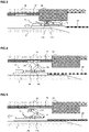
- FIG. 3 to FIG. 5 are each a schematic diagram illustrating the normal operation of the inspection device 11 according to the present embodiment.
- FIG. 3 is a schematic diagram illustrating insertion of the inspection device 11 into the rotary electric machine.
- the link mechanism 15 is in the most contracted state so as to allow the inspection device 11 to pass through the narrowest gap between the stator 2 and the rotor fastening ring 33.
- no external force is applied between the link connection portion 14a and the ball nut 14c of the connection mechanism 14 in the compression direction and the separating direction. Therefore, the link connection portion 14a and the ball nut 14c are connected to each other by a magnetic attraction force of the magnet 14b.
- the link mechanism 15 and the linear motion mechanism 13 are connected at the connection mechanism 14.
- FIG. 4 is a schematic diagram illustrating inspection of the rotor wedge 32 by the inspection device 11.
- the link mechanism 15 extends such that the inspection device 11 presses the inspection sensor 16 against the rotor wedge 32.
- an external force is applied between the link connection portion 14a and the ball nut 14c of the connection mechanism 14 in the separating direction.
- the external force is a force for allowing the inspection sensor 16 to have a pressing force for the inspection.
- connection between the link connection portion 14a and the ball nut 14c by the magnetic attraction force of the magnet 14b is maintained.
- FIG. 5 is a schematic diagram illustrating movement of the inspection device 11 to a subsequent inspection position.
- the inspection device 11 contracts the link mechanism 15 to an intermediate position so as to separate the inspection sensor 16 from the rotor wedge 32.
- no external force is applied between the link connection portion 14a and the ball nut 14c of the connection mechanism 14 in the compression direction and the separating direction, and the link connection portion 14a and the ball nut 14c are thus connected by the magnetic attraction force of the magnet 14b.
- the link mechanism 15 and the linear motion mechanism 13 are connected at the connection mechanism 14.
- the inspection device 11 is moved to a subsequent inspection position by the insertion bar 22.
- FIG. 6 to FIG. 8 are each a schematic diagram illustrating the emergency operation for the inspection device 11 according to the present embodiment.
- the emergency operation represents an operation of removing the inspection device 11 from the rotary electric machine in a case where abnormality occurs in the inspection device when the inspection device 11 is inspecting the rotor wedge 32.
- the abnormality in the inspection device represents a state where the linear motion mechanism 13 as a drive unit for the link mechanism 15 does not operate normally and the extending/contracting operation of the link mechanism 15 cannot be controlled.
- the linear motion mechanism 13 cannot operate normally due to, for example, a transmission path of a signal from the remote device 17 being disconnected or power supply to the linear motion mechanism 13 being stopped.
- FIG. 6 is a schematic diagram illustrating removal of the inspection device 11 with use of the insertion bar 22.
- the link mechanism 15 comes into contact with the rotor fastening ring 33.
- a force in the direction opposite to the removal direction acts on the link mechanism 15.
- the force acting on the link mechanism 15 acts so as to contract the link mechanism 15.
- a force in the direction opposite to the removal direction acts on the link connection portion 14a through the link mechanism 15.
- the link connection portion 14a When the force acting on the link connection portion 14a becomes higher than the magnetic attraction force by which the link connection portion 14a and the ball nut 14c are connected, the link connection portion 14a separates from the ball nut 14c. That is, the maximum connecting force between the link connection portion 14a and the ball nut 14c is a predetermined force, and, when a force higher than the predetermined force acts on the link mechanism 15, the link connection portion 14a and the ball nut 14c are disconnected.
- the link connection portion 14a has a certain degree of freedom in the linear motion direction, and is thus separated from the ball nut 14c along the linear motion direction.
- FIG. 7 illustrates a state where the link connection portion 14a is separated from the ball nut 14c.
- FIG. 8 illustrates a state where the inspection device 11 passes through the gap between the rotor fastening ring 33 and the stator 2.
- the inspection device having such a structure, in a case where an overload acts on the connection mechanism, the link connection portion and the ball nut are disconnected and the link connection portion is separated from the ball nut. Therefore, even in a case where the linear motion mechanism as the drive unit for an operation of extending/contracting the link mechanism does not operate normally, the link mechanism contracts. As a result, the inspection device can be removed without removing the rotor from the rotary electric machine and causing damage to the rotary electric machine and the inspection device.
- the overload acting on the connection mechanism is also generated by, for example, a reaction force of an excessive pressing force of the inspection sensor against the rotor wedge, in addition to a reaction force generated when the link mechanism comes into contact with the rotor fastening ring or a reaction force generated when the inspection sensor comes into contact with a stepped portion of the rotor wedge.
- the link connection portion is separated from the ball nut and moves so as to contract the link mechanism, whereby the pressing force of the inspection sensor is lowered.
- a connection force between the link connection portion and the ball nut is obtained by the magnetic attraction force of the magnet. Therefore, if the link connection portion and the ball nut are disconnected and the link connection portion and the ball nut are separated from each other in the rotary electric machine, the linear motion mechanism can move the ball nut close to the link connection portion separated therefrom and connect again the link connection portion and the ball nut to each other by using the magnetic attraction force of the magnet.
- the structure of the link mechanism is not limited to the structure illustrated in FIG. 2 , and the link mechanism may have another structure as long as the operation at all the paired portions except for the force application point and the fulcrum of the link mechanism has a movement component in a direction perpendicular to or the same direction as a direction in which a force acts on the force application point.
- the structure in which the link mechanism has two force application points can be a structure that satisfies the above-described condition on the assumption that one of the force application points is regarded as the fulcrum and a force is applied only to the other of the force application points.
- the link mechanism satisfying these conditions is, for example, the link mechanism 15 illustrated in FIG. 9 .
- the link mechanism 15 having one force application point is illustrated on the left side in FIG.
- the ball screw mechanism is used as the linear motion mechanism.
- Another mechanism such as a linear motor instead of the ball screw mechanism may be used as the linear motion mechanism.
- the link connection portion and the ball nut are connected by the magnetic attraction force of the magnet.
- the present disclosure is not limited thereto.
- the link connection portion and the ball nut may be fitted to each other by using an elastically deformable member and thus connected.
- the maximum connecting force by the fitting is set to be higher than a force applied to the force application point in the link mechanism for allowing the inspection sensor to have a pressing force for the inspection, and lower than a force applied to the force application point in the link mechanism for contracting the link mechanism in the emergency operation.
- FIG. 10 is a schematic diagram illustrating an inspection device according to embodiment 2.
- the inspection device 11 of the present embodiment is similar to the inspection device of embodiment 1, the base 12 has a holding magnet 18.
- the holding magnet 18 is disposed so as to come into contact with the connection mechanism 14 when the link mechanism 15 is in the most contracted state.
- FIG. 10 illustrates the inspection device 11 of the present embodiment in the most contracted state.
- the holding magnet 18 holds the link connection portion 14a of the connection mechanism 14 by a magnetic attraction force.
- the magnetic attraction force of the holding magnet 18 is set to be lower than the magnetic attraction force of the magnet 14b acting between the link connection portion 14a and the ball nut 14c.
- the holding magnet 18 attracts the link connection portion 14a by the magnetic attraction force to retain the link mechanism 15 in the most contracted state. Therefore, in the emergency operation, the link mechanism 15 can be prevented from unnecessarily extending. As a result, unnecessary contact between the rotor fastening ring 33, and the link mechanism 15 or the inspection sensor 16 can be prevented when the inspection device 11 is removed.
- the magnetic attraction force acting between the holding magnet 18 and the link connection portion 14a is set to be lower than the magnetic attraction force of the magnet 14b acting between the link connection portion 14a and the ball nut 14c. Therefore, the magnetic attraction force of the holding magnet 18 does not exert an influence on the extending/contracting operation of the link mechanism 15 according to the linear motion performed by the linear motion mechanism 13 in the normal operation.
- the holding magnet 18 is disposed so as to be separated from the bearing 13c of the linear motion mechanism 13, the holding magnet 18 may be disposed so as to be in contact with the bearing 13c.
- FIG. 11 is a schematic diagram illustrating an inspection device according to embodiment 3.
- the inspection device 11 of the present embodiment is similar to the inspection device of embodiment 1, the structure of the link mechanism 15 is different.
- the link mechanism 15 of the present embodiment is composed of the first link 15a, the second link 15b, and an expansion link 15c.
- the first link 15a acts as a driven link
- the second link 15b acts as a driving link
- the first link 15a and the second link 15b form a main link.
- the first link 15a, the second link 15b, and the expansion link 15c each include joints at both ends. One of the joints of the first link 15a is connected to the base 12.
- One of the joints of the expansion link 15c is connected to the other of the joints of the first link 15a.
- the inspection sensor 16 is connected to the other of the joints of the expansion link 15c.
- One of the joints of the second link 15b is connected to the link connection portion 14a.
- the other of the joints of the second link 15b is connected to the other of the joints of the first link 15a in a rotatable manner.
- the length of the expansion link 15c is greater than the length of each of the first link 15a and the second link 15b.
- the width of the expansion link 15c is shown to be greater than the width of each of the first link 15a and the second link 15b for facilitating the discrimination in the drawings. There is no problem also when the width of the expansion link 15c is equal to the width of each of the first link 15a and the second link 15b.
- FIG. 12 and FIG. 13 are each a schematic diagram illustrating an operation of the link mechanism according to the present embodiment.
- a state where the link mechanism 15 is contracted is illustrated on the left side
- a state where the link mechanism 15 is extended is illustrated on the right side.
- FIG. 12 illustrates an operation of the link mechanism 15 in which the expansion link 15c is fixed to the first link 15a.
- FIG. 13 illustrates an operation of the link mechanism 15 in which the expansion link 15c is fixed to the inspection sensor 16.
- a distance between paired portions is equal among the first link 15a, the second link 15b, and the expansion link 15c.
- a moving distance L1 of the inspection sensor 16 in a direction orthogonal to a direction of the motion performed by the linear motion mechanism 13 is almost equal to a distance L2 of the motion performed by the linear motion mechanism 13.
- a moving distance L3 of the inspection sensor 16 in a direction orthogonal to a direction of the motion performed by the linear motion mechanism 13 is about 1/2 of a distance L4 of the motion performed by the linear motion mechanism 13.
- a thrust force through the link mechanism is known to be inversely proportional to a ratio between a moving distance of the force application point and a moving distance of a point of action.
- the link mechanism 15 illustrated in FIG. 12 and FIG. 13 in a case where a thrust force generated at the linear motion mechanism 13 is equal, the closer the link mechanism 15 is to the most contracted state, the lower a pressing force of the inspection sensor 16 is.
- the pressing force of the inspection sensor 16 needs to be set with reference to the rotary electric machine having the specifications in which a distance from the inner circumferential surface of the stator to the rotor wedge is shortest.
- a moving distance of the inspection sensor 16 can be changed relative to a distance of the motion performed by the linear motion mechanism 13.
- the minimum thrust force required for the linear motion mechanism can be reduced.
- the size of the linear motion mechanism can be reduced and the thickness of the inspection device can be reduced.
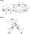
- FIG. 14 is a schematic diagram illustrating another link mechanism of the present embodiment.
- the link mechanism 15 illustrated in FIG. 14 is composed of the first link 15a, the second link 15b, and three expansion links 15c, 15d, and 15e.
- the first link 15a acts as a driven link
- the second link 15b acts as a driving link
- the first link 15a and the second link 15b form a main link.
- the first link 15a, the second link 15b, and the three expansion links 15c, 15d, and 15e each have joints at both ends.
- One of the joints of the first link 15a is connected to one of the joints of the expansion link 15d.
- the other of the joints of the expansion link 15d is connected to the base.
- the other of the joints of the first link 15a is connected to one of the joints of the expansion link 15c.
- the inspection sensor 16 is connected to the other of the joints of the expansion link 15c.
- One of the joints of the second link 15b is connected to one of the joints of the expansion link 15e.
- the other of the joints of the expansion link 15e is connected to the link connection portion.
- the other of the joints of the second link 15b is connected to the other of the joints of the first link 15a in a rotatable manner.
- the length of each of the expansion links 15c, 15d, and 15e is greater than the length of each of the first link 15a and the second link 15b.
- the width of each of the expansion links 15c, 15d, and 15e is shown to be greater than the width of each of the first link 15a and the second link 15b for facilitating the discrimination in the drawings. There is no problem also when the width of each of the expansion links 15c, 15d, and 15e is equal to the width of each of the first link 15a and the second link 15b.
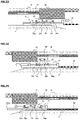
- FIG. 15, FIG. 16, and FIG. 17 are each a schematic diagram illustrating an operation of another link mechanism of the present embodiment.
- a state where the link mechanism 15 is contracted is illustrated on the left side
- a state where the link mechanism 15 is extended is illustrated on the right side.
- FIG. 15 illustrates an operation of the link mechanism 15 in which the expansion link 15c and the expansion link 15d are fixed to the first link 15a, and the expansion link 15e is fixed to the second link 15b.
- FIG. 16 illustrates an operation of the link mechanism 15 in which the expansion link 15c is fixed to the inspection sensor 16, the expansion link 15d is fixed to the first link 15a, and the expansion link 15e is fixed to the second link 15b.
- FIG. 15 illustrates an operation of the link mechanism 15 in which the expansion link 15c is fixed to the inspection sensor 16, the expansion link 15d is fixed to the first link 15a, and the expansion link 15e is fixed to the second link 15b.
- FIG. 17 illustrates an operation of the link mechanism 15 in which the expansion link 15e is fixed to the link connection portion, and the expansion link 15d is fixed to the base.
- a distance between the paired portions is equal among the first link 15a, the second link 15b, and the expansion links 15c, 15d, and 15e.
- a moving distance L3 of the inspection sensor 16 in a direction orthogonal to a direction of the motion performed by the linear motion mechanism 13 is about 1/2 of a distance L4 of the motion performed by the linear motion mechanism 13.
- a moving distance L5 of the inspection sensor 16 in a direction orthogonal to a direction of the motion performed by the linear motion mechanism 13 is about 1/2 of a distance L6 of the motion performed by the linear motion mechanism 13.
- the moving distance of the inspection sensor 16 can be changed relative to the distance of the motion performed by the linear motion mechanism 13.
- the minimum thrust force required for the linear motion mechanism 13 can be reduced.
- the size of the linear motion mechanism can be reduced and the thickness of the inspection device can be reduced.
- a movable distance obtained by the linear motion mechanism in the link mechanism 15 illustrated in FIG. 17 is about half a movable distance obtained by the linear motion mechanism in the link mechanisms 15 illustrated in FIG. 15 and FIG. 16 .
- a speed of the motion performed by the linear motion mechanism is equal, rising of the extension of the link mechanism 15 illustrated in FIG. 17 occurs in a shorter time period than that of the link mechanisms 15 illustrated in FIG. 15 and FIG. 16 . Therefore, the link mechanism 15 illustrated in FIG. 17 can enhance a pressing force of the inspection sensor 16 at a shorter distance of the linear motion performed by the linear motion mechanism.
- the expansion links 15c, 15d, and 15e are disposed so as to interpose the first link 15a and the second link 15b therebetween.
- the link mechanism of the present embodiment is not limited to such a structure.
- a link mechanism including at least one of the expansion links 15c, 15d, and 15e of the link mechanism illustrated in FIG. 14 may be used.
- a link mechanism including at least two of the expansion links 15c, 15d, and 15e of the link mechanism illustrated in FIG. 14 may be used.
- the expansion links 15c, 15d, and 15e may be each formed of a plurality of links.
- FIG. 18 is a schematic diagram illustrating an inspection device according to embodiment 4.
- the inspection device 11 of the present embodiment includes the base 12, an opposing-movement-type linear motion mechanism 23, a first connection mechanism 24, a second connection mechanism 26, a link mechanism 25, and the inspection sensor 16.
- the opposing-movement-type linear motion mechanism 23 is, for example, a ball screw mechanism, and is composed of a ball screw 23a, a motor 23b, and a bearing 23c. To the ball screw 23a, the first connection mechanism 24 and the second connection mechanism 26 are connected.
- the opposing-movement-type linear motion mechanism 23 has a function of linearly moving the first connection mechanism 24 and the second connection mechanism 26 connected to the ball screw 23a over the same distance in opposite directions at the same time. Examples of the mechanism for such an operation include a pair of normal-thread and reverse-thread ball screw mechanisms.
- the motor 23b rotates in response to a signal from an external remote device 17, and linearly moves the first connection mechanism 24 and the second connection mechanism 26 through the ball screw 23a over the same distance in opposite directions at the same time. For example, when the motor 23b rotates forward, the opposing-movement-type linear motion mechanism 23 moves the first connection mechanism 24 leftward and simultaneously moves the second connection mechanism 26 rightward. When the motor 23b rotates reversely, the opposing-movement-type linear motion mechanism 23 moves the first connection mechanism 24 rightward and simultaneously moves the second connection mechanism 26 leftward.
- the first connection mechanism 24 is composed of a first link connection portion 24a, a magnet 24b, and a ball nut 24c.
- the ball nut 24c is linearly moved by rotation of the ball screw 23a of the opposing-movement-type linear motion mechanism 23. That is, the ball nut 24c is an interlocking portion that moves in conjunction with the linear motion performed by the opposing-movement-type linear motion mechanism 23 at the first connection mechanism 24.
- the first link connection portion 24a is formed as a metal magnetic body, and is connected to the ball nut 24c by a magnetic attraction force of the magnet 24b.
- the first link connection portion 24a does not move in direct conjunction with the linear motion performed through the ball screw 23a by the opposing-movement-type linear motion mechanism 23, and is retained with a certain degree of freedom in the direction of the linear motion performed by the opposing-movement-type linear motion mechanism.
- the first link connection portion 24a is supported by a not-illustrated linear motion guide disposed parallel to a direction of the linear motion performed by the opposing-movement-type linear motion mechanism 23.
- the first link connection portion 24a has a through hole through which the ball screw 23a penetrates, and the first link connection portion 24a is supported by the ball screw 23a via the through hole.
- the second connection mechanism 26 is composed of a second link connection portion 26a, a magnet 26b, and a ball nut 26c.
- the structure of the second connection mechanism 26 is almost the same as the structure of the first connection mechanism 24.
- the ball nut 26c is linearly moved by rotation of the ball screw 23a of the opposing-movement-type linear motion mechanism 23. That is, the ball nut 26c is an interlocking portion that moves in conjunction with the linear motion performed by the opposing-movement-type linear motion mechanism 23 at the second connection mechanism 26.
- the second link connection portion 26a does not move in direct conjunction with the linear motion performed through the ball screw 23a by the opposing-movement-type linear motion mechanism 23, and is retained with a certain degree of freedom in the direction of the linear motion performed by the opposing-movement-type linear motion mechanism.
- the first link connection portion 24a and the second link connection portion 26a are disposed outward of the ball nut 24c and the ball nut 26c, respectively.
- a maximum connecting force between the first link connection portion 24a and the ball nut 24c by the magnetic attraction force is set to be higher than a force applied to a force application point in the link mechanism 25 for allowing the inspection sensor 16 to have a pressing force for the inspection, and lower than a force applied to a force application point in the link mechanism 25 for contracting the link mechanism 25 in an emergency operation.
- a maximum connecting force between the second link connection portion 26a and the ball nut 26c by the magnetic attraction force is set to be higher than a force applied to a force application point in the link mechanism 25 for allowing the inspection sensor 16 to have a pressing force for the inspection and lower than a force applied to a force application point in the link mechanism 25 for contacting the link mechanism 25 in an emergency operation.
- the link mechanism 25 is composed of a first link 25a and a second link 25b.
- the link mechanism 25 is structured to have no fulcrum and move by two force application points.
- the first link 25a and the second link 25b each include joints at both ends.
- One of the joints of the first link 25a is connected to the first link connection portion 24a.
- the inspection sensor 16 is connected to the other of the joints of the first link 25a.
- One of the joints of the second link 25b is connected to the second link connection portion 26a.
- the inspection sensor 16 is connected to the other of the joints of the second link 25b.
- the link mechanism 25 transforms the movement of the first link connection portion 24a and the second link connection portion 26a in the left-right direction in FIG. 18 to the movement of the inspection sensor 16 in the up-down direction in FIG.
- a stroke of the opposing-movement-type linear motion mechanism 23 needs to be set such that the link mechanism 25 can linearly move and the link mechanism 25 can be most contracted to be minimized.
- the stroke of the opposing-movement-type linear motion mechanism 23 is set as a length that is four or more times the distance between the paired portions.
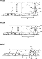
- FIG. 19 to FIG. 21 are each a schematic diagram illustrating the normal operation of the inspection device 11 according to the present embodiment.
- FIG. 19 is a schematic diagram illustrating insertion of the inspection device 11 into the rotary electric machine. As illustrated in FIG. 19 , when the inspection device 11 is inserted into the rotary electric machine, the link mechanism 25 is in the most contracted state so as to allow the inspection device 11 to pass through the narrowest gap between the stator 2 and the rotor fastening ring 33. At this time, no external force is applied between the first link connection portion 24a and the ball nut 24c of the first connection mechanism 24 in the compression direction and the separating direction.
- the first link connection portion 24a and the ball nut 24c are connected to each other by the magnetic attraction force of the magnet 24b.
- no external force is applied between the second link connection portion 26a and the ball nut 26c of the second connection mechanism 26 in the compression direction and the separating direction. Therefore, the second link connection portion 26a and the ball nut 26c are connected to each other by the magnetic attraction force of the magnet 26b.
- the link mechanism 25 and the opposing-movement-type linear motion mechanism 23 are connected at the first connection mechanism 24 and the second connection mechanism 26.
- FIG. 20 is a schematic diagram illustrating inspection of the rotor wedge 32 by the inspection device 11.
- the link mechanism 25 extends such that the inspection device 11 presses the inspection sensor 16 against the rotor wedge 32.
- an external force is applied between the first link connection portion 24a and the ball nut 24c of the first connection mechanism 24 in the separating direction.
- connection between the first link connection portion 24a and the ball nut 24c is maintained.
- connection between the second link connection portion 26a and the ball nut 26c is maintained.
- the link mechanism 25 and the opposing-movement-type linear motion mechanism 23 are connected at the first connection mechanism 24 and the second connection mechanism 26.
- FIG. 21 is a schematic diagram illustrating movement of the inspection device 11 to a subsequent inspection position.
- the inspection device 11 contracts the link mechanism 25 to the intermediate position so as to separate the inspection sensor 16 from the rotor wedge 32.
- No external force is applied between the first link connection portion 24a and the ball nut 24c of the first connection mechanism 24 in the compression direction and the separating direction, and the first link connection portion 24a and the ball nut 24c are thus connected by the magnetic attraction force of the magnet 24b.
- the second link connection portion 26a and the ball nut 26c are connected by the magnetic attraction force of the magnet 26b.
- the link mechanism 25 and the opposing-movement-type linear motion mechanism 23 are connected at the first connection mechanism 24 and the second connection mechanism 26.
- the inspection device 11 is moved to a subsequent inspection position by the insertion bar 22.
- FIG. 20 to FIG. 21 are repeated, whereby the inspection device 11 can inspect the rotary electric machine.
- the first link connection portion 24a, the magnet 24b, and the ball nut 24c are integrally moved in the first connection mechanism 24, and, similarly, the second link connection portion 26a, the magnet 26b, and the ball nut 26c are integrally moved in the second connection mechanism 26.
- FIG. 22 to FIG. 25 are each a schematic diagram illustrating the emergency operation for the inspection device 11 according to the present embodiment.
- the emergency operation represents an operation of removing the inspection device 11 from the rotary electric machine in a case where abnormality occurs in the inspection device when the inspection device 11 is inspecting the rotor wedge 32.
- the abnormality in the inspection device represents a state where the opposing-movement-type linear motion mechanism 23 does not operate normally and the extending/contracting operation of the link mechanism 25 cannot be controlled.
- a case where abnormality occurs in the inspection device 11 in the state illustrated in FIG. 21 is assumed.
- the link mechanism 25 has been extended to the intermediate position.
- the first link connection portion 24a and the ball nut 24c of the first connection mechanism 24 are connected by the magnetic attraction force of the magnet 24b.
- the second link connection portion 26a and the ball nut 26c of the second connection mechanism 26 are connected by the magnetic attraction force of the magnet 26b.
- FIG. 22 is a schematic diagram illustrating removal of the inspection device 11 from the right side with use of the insertion bar 22.
- the link mechanism 25 of the inspection device 11 has been extended, so that the link mechanism 25 comes into contact with the rotor fastening ring 33 on the right side.
- a force in the direction opposite to the removal direction acts on the link mechanism 25.
- a force in the direction opposite to the removal direction acts on the first link connection portion 24a through the link mechanism 25.
- the first link connection portion 24a When the force acting on the first link connection portion 24a becomes higher than the magnetic attraction force by which the first link connection portion 24a and the ball nut 24c are connected, the first link connection portion 24a separates from the ball nut 24c. That is, the maximum connecting force between the first link connection portion 24a and the ball nut 24c is a predetermined force, and, when a force higher than the predetermined force acts on the link mechanism 25, the first link connection portion 24a and the ball nut 24c are disconnected.
- the first link connection portion 24a has a certain degree of freedom in the linear motion direction, and is thus separated from the ball nut 24c along the linear motion direction.
- FIG. 22 illustrates a state where the first link connection portion 24a is separated from the ball nut 24c.
- the first link connection portion 24a is moved so as to be separated from the ball nut 24c, whereby the link mechanism 25 contracts.
- the position of the inspection sensor 16 is lowered, and the link mechanism 25 contracts so as to allow the inspection device 11 to pass through a gap between the rotor fastening ring 33 on the right side and the stator 2.
- FIG. 23 illustrates a state where the inspection device 11 passes through the gap between the rotor fastening ring 33 on the right side and the stator 2.
- FIG. 24 is a schematic diagram illustrating removal of the inspection device 11 from the left side with use of the insertion bar 22.
- the link mechanism 25 of the inspection device 11 has been extended, so that the link mechanism 25 comes into contact with the rotor fastening ring 33 on the left side.
- a force in the direction opposite to the removal direction acts on the link mechanism 25.
- a force in the direction opposite to the removal direction acts on the second link connection portion 26a through the link mechanism 25.
- the second link connection portion 26a When the force acting on the second link connection portion 26a becomes higher than the magnetic attraction force by which the second link connection portion 26a and the ball nut 26c are connected, the second link connection portion 26a separates from the ball nut 26c. That is, the maximum connecting force between the second link connection portion 26a and the ball nut 26c is a predetermined force, and, when a force higher than the predetermined force acts on the link mechanism 25, the second link connection portion 26a and the ball nut 26c are disconnected.
- the second link connection portion 26a has a certain degree of freedom in the linear motion direction, and is thus separated from the ball nut 26c along the linear motion direction.
- FIG. 24 illustrates a state where the second link connection portion 26a is separated from the ball nut 26c.
- the second link connection portion 26a is moved so as to be separated from the ball nut 26c, whereby the link mechanism 25 contracts.
- the position of the inspection sensor 16 is lowered, and the link mechanism 25 contracts so as to allow the inspection device 11 to pass through a gap between the rotor fastening ring 33 on the left side and the stator 2.
- FIG. 25 illustrates a state where the inspection device 11 passes through the gap between the rotor fastening ring 33 on the left side and the stator 2.
- the inspection device having such a structure, in a case where an overload acts on the first connection mechanism or the second connection mechanism, the ball nut and the first link connection portion or the second link connection portion are disconnected, and the first link connection portion or the second link connection portion is separated from the ball nut, whereby the link mechanism 25 contracts.
- the inspection device can be removed without removing the rotor from the rotary electric machine and causing damage to the rotary electric machine and the inspection device.
- the inspection device can be removed by moving the inspection device in either direction. Therefore, the inspection device can be quickly removed from the end portion, of the rotary electric machine, closer to a position at which abnormality has occurred.
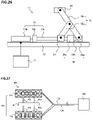
- FIG. 26 is a schematic diagram illustrating an inspection device according to embodiment 5.
- the inspection device 11 is composed of the elongated base 12, the linear motion mechanism 13, a third connection mechanism 34, the link mechanism 15, a fourth connection mechanism 36, and the inspection sensor 16.
- the base 12 is, for example, a metal member to which the linear motion mechanism 13, the fourth connection mechanism 36, and the like are mounted.
- the linear motion mechanism 13 is, for example, a ball screw mechanism, and is composed of a ball screw 13a, a motor 13b, and a bearing 13c.
- the third connection mechanism 34 is connected to the ball screw 13a.
- the linear motion mechanism 13 rotates the motor 13b in response to a signal from an external remote device 17 and linearly moves the third connection mechanism 34 through the ball screw 13a.
- the third connection mechanism 34 moves in conjunction with the linear motion performed by the linear motion mechanism 13.
- the fourth connection mechanism 36 is composed of a link connection portion 36a, a magnet 36b, and a fixing portion 36c.
- the fixing portion 36c is fixed to the base 12.
- the magnet 36b is fixed to the fixing portion 36c.
- the link connection portion 36a is formed as a metal magnetic body, and is connected to the fixing portion 36c by a magnetic attraction force of the magnet 36b.
- the link connection portion 36a may be structured to incorporate a magnet other than the magnet 36b.
- the link connection portion 36a is not connected directly to the base 12 and is connected to the fixing portion 36c by the magnetic attraction force of the magnet 36b. That is, the link connection portion 36a is a separable portion in the fourth connection mechanism 36.
- the link connection portion 36a and the fixing portion 36c of the fourth connection mechanism 36 are connected by the magnetic attraction force of the magnet 36b.
- the magnet 36b may be fixed to the link connection portion 36a.
- the fixing portion 36c needs to be formed as a magnetic body or needs to incorporate another magnet.
- a maximum connecting force between the link connection portion 36a and the fixing portion 36c by the magnetic attraction force is set to be higher than a force applied to a force application point in the link mechanism 15 for allowing the inspection sensor 16 to have a pressing force and lower than a force applied to a force application point in the link mechanism 15 for contracting the link mechanism 15 in an emergency operation.
- the link mechanism 15 is composed of a first link 15a and a second link 15b.
- the first link 15a and the second link 15b each include joints at both ends.
- One of the joints of the first link 15a is connected to the link connection portion 36a.
- the inspection sensor 16 is connected to the other of the joints of the first link 15a.
- One of the joints of the second link 15b is connected to the third connection mechanism 34.
- the other of the joints of the second link 15b is connected to almost the center of the first link 15a in a rotatable manner.
- the first link 15a acts as a driven link and the second link 15b acts as a driving link.
- the maximum connecting force between the link connection portion 36a and the fixing portion 36c is a predetermined force, and, when a force higher than the predetermined force acts on the link mechanism 15, the link connection portion 36a and the fixing portion 36c are disconnected.
- the link connection portion 36a is moved so as to be separated from the fixing portion 36c, whereby the link mechanism 15 contracts.
- the position of the inspection sensor 16 is lowered, and the link mechanism 15 contracts so as to allow the inspection device 11 to pass through a gap between the rotor fastening ring and the stator.
- the inspection device 11 can be removed from the rotary electric machine.
- the inspection device having such a structure, in a case where an overload acts on the fourth connection mechanism, the link connection portion and the fixing portion are disconnected and the link connection portion is separated from the fixing portion. Therefore, even in a case where the linear motion mechanism as the drive unit for an operation of extending/contracting the link mechanism does not operate normally, the link mechanism contracts. As a result, the inspection device can be removed without removing the rotor from the rotary electric machine and causing damage to the rotary electric machine and the inspection device.
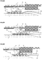
- FIG. 27 is a schematic diagram illustrating an inspection system according to embodiment 6.
- the inspection system of the present embodiment includes the inspection device of embodiment 1.
- an inspection system 100 of the present embodiment includes the inspection device 11, a movable body 101, a control unit 102, a control cable 103, and an emergency rope 104.
- the movable body 101 is composed of a first movable body 101a and a second movable body 101b.
- the first movable body 101a and the second movable body 101b each include a traveling apparatus such as an endless track.
- the inspection device 11 is joined to the first movable body 101a and the second movable body 101b at a position between the first movable body 101a and the second movable body 101b by using connecting members 105.
- the control unit 102 outputs control signals for controlling the movable body 101 and the inspection device 11.
- the control cable 103 transmits control signals outputted by the control unit 102 to the movable body 101 and the inspection device 11.
- the emergency rope 104 is connected to the movable body 101, and is used when the movable body 101 is removed from the rotary electric machine in a case where a failure occurs in the traveling apparatus of the movable body 101.
- the control cable 103 and the emergency rope 104 are connected to the movable body 101, the control cable 103 and the emergency rope 104 may be connected to the inspection device 11.
- the control cable 103 may serve also as the emergency rope 104 without providing the emergency rope 104.
- FIG. 28 to FIG. 30 are each a schematic diagram illustrating an example of an operation of the inspection system 100 of the present embodiment.
- the inspection system 100 moves in a state where the movable body 101 is in contact with the inner circumferential surface of the stator 2.
- the inspection system 100 presses the inspection sensor 16 of the inspection device 11 against the rotor wedge 32 and preforms the inspection.
- FIG. 28 illustrates a normal operation of the inspection system 100.
- the inspection system 100 is moved, by the movable body 101, to an inspection position.
- the inspection system 100 repeatedly performs an operation of extending the link mechanism for pressing the inspection sensor 16 against the rotor wedge 32, and an operation of contracting the link mechanism for separating the inspection sensor 16 from the rotor wedge 32.
- the inspection system 100 inspects the rotor 3 while moving on the inner circumferential surface of the stator 2.
- FIG. 29 illustrates a state where abnormality has occurred in the linear motion mechanism of the inspection device 11.
- the inspection system 100 is moved to the end portion of the rotor fastening ring 33.
- the emergency rope 104 provided in the inspection system 100 is pulled from the outside of the rotary electric machine, to move the inspection system 100 to the end portion of the rotor fastening ring 33.
- FIG. 30 illustrates a state where the inspection system 100 passes through a gap between the rotor fastening ring 33 and the stator 2.
- the inspection system 100 that has reached the end portion of the rotor fastening ring 33 further moves the movable body 101 backward.
- a function of the emergency operation for the inspection device 11 operates. That is, the link connection portion and the ball nut of the connection mechanism of the inspection device 11 are disconnected, and the link connection portion is separated from the ball nut, whereby the link mechanism 15 contracts.
- the inspection system 100 can pass through the gap between the rotor fastening ring 33 and the stator 2.
- the inspection system of the present embodiment includes the inspection device of embodiment 1.
- the inspection system may include the inspection device of any of embodiments 2 to 5 instead of the inspection device of embodiment 1.
Landscapes
- Engineering & Computer Science (AREA)
- Power Engineering (AREA)
- Microelectronics & Electronic Packaging (AREA)
- Physics & Mathematics (AREA)
- General Physics & Mathematics (AREA)
- Manufacturing & Machinery (AREA)
- Testing Of Devices, Machine Parts, Or Other Structures Thereof (AREA)
- Manufacture Of Motors, Generators (AREA)
- Transmission Devices (AREA)
Abstract
Description
- The present disclosure relates to an inspection device for a rotary electric machine and an inspection system for a rotary electric machine.
- A rotor wedge for holding a copper winding is inserted in a rotor of a large-sized rotary electric machine used as an electric generator. A defect such as a crack at a surface of the rotor wedge may cause a failure in the rotary electric machine. In general, the rotor needs to be removed from the rotary electric machine in order to inspect the rotor wedge for the defect. In a case where the rotor is removed from the rotary electric machine and inspected, many problems arise. For example, the rotary electric machine is stopped for a long time period, or the rotor or a stator may be damaged when the rotor is dismounted or mounted.
- A method in which, in a state where the rotor is mounted to the rotary electric machine, an inspection device is inserted in a gap between the rotor and the stator and the inspection device is operated by a remote device to inspect the rotor wedge for a defect, is disclosed as a method for addressing these problems. The inspection device includes an extending/contracting mechanism having an inspection sensor mounted at the end thereof. The inspection device is inserted into the rotary electric machine in a state where the extending/contracting mechanism is contracted. When the inspection device has reached an inspection position, the extending/contracting mechanism of the inspection device is extended to bring the inspection sensor into close contact with the rotor (for example, see Patent Document 1).
- Patent Document 1:
Japanese Laid-Open Patent Publication No. 2017-138315 - In general, a rotor fastening ring is disposed at the end portion of the rotor. In general, the outer diameter of the rotor fastening ring is set to be greater than the rotor outer diameter in the rotor. Therefore, a gap between the rotor fastening ring and the stator at the end portion of the rotary electric machine is narrower than a gap between the rotor and the stator inside the rotary electric machine.
- A conventional inspection device stops in a state where an extending/contracting mechanism is extended in a case where a failure occurs in a drive unit for the extending/contracting mechanism in a state where the extending/contracting mechanism is extended after the inspection device has been inserted into the rotary electric machine. Therefore, the inspection device cannot pass through the gap between the rotor fastening ring and the stator. Accordingly, the rotor needs to be removed from the rotary electric machine in order to remove the inspection device without causing damage to the rotary electric machine and the inspection device.
- The present disclosure has been made in order to solve the aforementioned problems, and an inspection device of the present disclosure can be removed from a rotary electric machine without removing a rotor even in a case where a failure occurs in a drive unit for an extending/contracting mechanism in a state where the inspection device has been inserted in the rotary electric machine.
- An inspection device of the present disclosure includes: a base; a linear motion mechanism mounted to the base for performing linear motion; a link mechanism which has a driving link, and a driven link that is connected to the base, and which extends/contracts, by the linear motion performed by the linear motion mechanism, in a direction intersecting a direction of the linear motion; a connection mechanism for connecting between the driving link of the link mechanism and the linear motion mechanism; and a sensor mounted to the link mechanism. The connection mechanism has a link connection portion connected to the driving link, and an interlocking portion that is connected to the link connection portion and that moves in conjunction with the linear motion performed by the linear motion mechanism. When a force higher than or equal to a predetermined force is applied to the link mechanism, the link connection portion and the interlocking portion are disconnected, and the link connection portion is separated from the interlocking portion so as to contract the link mechanism.
- The inspection device of the present disclosure includes the connection mechanism in which, when a force higher than or equal to a predetermined force is applied to the link mechanism, the link connection portion and the interlocking portion are disconnected and the link connection portion is separated from the interlocking portion so as to contract the link mechanism. Therefore, even in a case where the linear motion mechanism does not operate normally, the link mechanism can be contracted. As a result, even in a case where a failure occurs in the drive unit for the extending/contracting mechanism in the inspection device after the inspection device has been inserted in a rotary electric machine, the inspection device can be removed without removing the rotor from the rotary electric machine.
-
- [
FIG. 1] FIG. 1 is a schematic diagram illustrating a cross-section of a rotary electric machine according toembodiment 1. - [
FIG. 2] FIG. 2 is a schematic diagram illustrating an inspection device according toembodiment 1. - [
FIG. 3] FIG. 3 is a schematic diagram illustrating a normal operation of the inspection device according toembodiment 1. - [
FIG. 4] FIG. 4 is a schematic diagram illustrating the normal operation of the inspection device according toembodiment 1. - [
FIG. 5] FIG. 5 is a schematic diagram illustrating the normal operation of the inspection device according toembodiment 1. - [
FIG. 6] FIG. 6 is a schematic diagram illustrating an emergency operation for the inspection device according toembodiment 1. - [
FIG. 7] FIG. 7 is a schematic diagram illustrating the emergency operation for the inspection device according toembodiment 1. - [
FIG. 8] FIG. 8 is a schematic diagram illustrating the emergency operation for the inspection device according toembodiment 1. - [
FIG. 9] FIG. 9 is a schematic diagram illustrating a structure of a link mechanism according toembodiment 1; - [
FIG. 10] FIG. 10 is a schematic diagram illustrating an inspection device according toembodiment 2. - [
FIG. 11] FIG. 11 is a schematic diagram illustrating an inspection device according toembodiment 3. - [
FIG. 12] FIG. 12 is a schematic diagram illustrating an operation of a link mechanism according toembodiment 3. - [
FIG. 13] FIG. 13 is a schematic diagram illustrating an operation of the link mechanism according toembodiment 3. - [
FIG. 14] FIG. 14 is a schematic diagram illustrating the link mechanism according toembodiment 3. - [
FIG. 15] FIG. 15 is a schematic diagram illustrating an operation of the link mechanism according toembodiment 3. - [
FIG. 16] FIG. 16 is a schematic diagram illustrating an operation of the link mechanism according toembodiment 3. - [
FIG. 17] FIG. 17 is a schematic diagram illustrating an operation of the link mechanism according toembodiment 3. - [
FIG. 18] FIG. 18 is a schematic diagram illustrating an inspection device according to embodiment 4. - [
FIG. 19] FIG. 19 is a schematic diagram illustrating a normal operation of the inspection device according to embodiment 4. - [
FIG. 20] FIG. 20 is a schematic diagram illustrating the normal operation of the inspection device according to embodiment 4. - [
FIG. 21] FIG. 21 is a schematic diagram illustrating the normal operation of the inspection device according to embodiment 4. - [
FIG. 22] FIG. 22 is a schematic diagram illustrating an emergency operation for the inspection device according to embodiment 4. - [
FIG. 23] FIG. 23 is a schematic diagram illustrating the emergency operation for the inspection device according to embodiment 4. - [
FIG. 24] FIG. 24 is a schematic diagram illustrating the emergency operation for the inspection device according to embodiment 4. - [
FIG. 25] FIG. 25 is a schematic diagram illustrating the emergency operation for the inspection device according to embodiment 4. - [
FIG. 26] FIG. 26 is a schematic diagram illustrating an inspection device according toembodiment 5. - [
FIG. 27] FIG. 27 is a schematic diagram illustrating an inspection system according to embodiment 6. - [
FIG. 28] FIG. 28 is a schematic diagram illustrating an operation of the inspection system according to embodiment 6. - [
FIG. 29] FIG. 29 is a schematic diagram illustrating the operation of the inspection system according to embodiment 6. - [
FIG. 30] FIG. 30 is a schematic diagram illustrating the operation of the inspection system according to embodiment 6. - An inspection device for a rotary electric machine and an inspection system for a rotary electric machine according to an embodiment for implementing the present disclosure will be described below in detail with reference to the drawings. The same or corresponding components throughout the drawings are denoted by the same reference characters.
-
FIG. 1 is a schematic diagram illustrating a cross-section of a rotary electric machine to be inspected by an inspection device according toembodiment 1. The rotary electric machine inFIG. 1 is a large-sized rotary electric machine used as, for example, an electric generator. A rotaryelectric machine 1 is composed of astator 2 and arotor 3. Thestator 2 has a cylindrical shape. Therotor 3 has a columnar shape, is disposed in thestator 2, and is rotatable relative to thestator 2. Therotor 3 includes arotor shaft 31, arotor wedge 32, and arotor fastening ring 33. Therotor wedge 32 is disposed on the surface of therotor shaft 31, and has a function of holding a winding of therotor 3. The entire surface of therotor wedge 32 may not necessarily be disposed at the same position as the surface of therotor shaft 31, and some surfaces of therotor wedge 32 may be disposed at a deeper side position relative to the inner diameter than the surface of therotor shaft 31. An outer diameter of therotor fastening ring 33 is set to be greater than an outer diameter of therotor shaft 31. Therefore, a gap between thestator 2 and therotor 3 at the end portion of the rotaryelectric machine 1 is narrower than a gap between thestator 2 and therotor 3 inside the rotaryelectric machine 1. For example, the gap between thestator 2 and therotor 3 at the end portion at which therotor fastening ring 33 is disposed is about 2 cm. Aninspection device 11 of the present embodiment is inserted into the gap between thestator 2 and therotor 3 by using aninsertion bar 22. Theinspection device 11 is fixed to the tip of theinsertion bar 22. -
FIG. 2 is a schematic diagram illustrating the inspection device according to the present embodiment. Theinspection device 11 is composed of anelongated base 12, alinear motion mechanism 13, aconnection mechanism 14, alink mechanism 15, and aninspection sensor 16. Thebase 12 is, for example, a metal member to which thelinear motion mechanism 13, thelink mechanism 15, and the like are mounted. - The
linear motion mechanism 13 is, for example, a ball screw mechanism, and is composed of aball screw 13a, amotor 13b, and abearing 13c. Theconnection mechanism 14 is connected to theball screw 13a. Thelinear motion mechanism 13 rotates themotor 13b in response to a signal from an externalremote device 17, and linearly moves theconnection mechanism 14 through theball screw 13a. - The
connection mechanism 14 is composed of alink connection portion 14a, amagnet 14b, and aball nut 14c. Theball nut 14c is linearly moved by rotation of theball screw 13a of thelinear motion mechanism 13. That is, theball nut 14c is an interlocking portion that moves in conjunction with the linear motion performed by thelinear motion mechanism 13 at theconnection mechanism 14. Themagnet 14b is fixed to theball nut 14c. Thelink connection portion 14a is formed as a metal magnetic body, and is connected to theball nut 14c by a magnetic attraction force of themagnet 14b. Thelink connection portion 14a may be structured to incorporate a magnet other than themagnet 14b. Thelink connection portion 14a does not move in direct conjunction with the linear motion performed through theball screw 13a by thelinear motion mechanism 13, and is retained with a certain degree of freedom in the direction of the linear motion performed by thelinear motion mechanism 13. That is, thelink connection portion 14a is a separate portion relative to thelinear motion mechanism 13 at theconnection mechanism 14. For example, thelink connection portion 14a is supported by a not-illustrated linear motion guide disposed parallel to the direction of the linear motion performed by thelinear motion mechanism 13. Alternatively, thelink connection portion 14a has a through hole through which theball screw 13a penetrates, and thelink connection portion 14a is supported by theball screw 13a via the through hole. Therefore, in a case where no external force is applied, thelink connection portion 14a and theball nut 14c of theconnection mechanism 14 are connected by a magnetic attraction force of themagnet 14b. Then, theconnection mechanism 14 moves in conjunction with the linear motion performed by thelinear motion mechanism 13, and theconnection mechanism 14 and thelinear motion mechanism 13 integrally move. From the viewpoint that thelink connection portion 14a and theball nut 14c need to be connected by a magnetic attraction force, themagnet 14b may be fixed to thelink connection portion 14a. In this case, theball nut 14c needs to be formed as a magnetic body or needs to incorporate another magnet. - A maximum connecting force between the
link connection portion 14a and theball nut 14c by the magnetic attraction force is set to be higher than a force applied to a force application point in thelink mechanism 15 for allowing theinspection sensor 16 to have a pressing force as described below, and lower than a force applied to a force application point in thelink mechanism 15 for contracting thelink mechanism 15 in an emergency operation. - The
link mechanism 15 is composed of afirst link 15a and asecond link 15b. Thefirst link 15a and thesecond link 15b each include joints at both ends. One of the joints of thefirst link 15a is connected to thebase 12. Theinspection sensor 16 is connected to the other of the joints of thefirst link 15a. One of the joints of thesecond link 15b is connected to thelink connection portion 14a. The other of the joints of thesecond link 15b is connected to thefirst link 15a in a rotatable manner. In thelink mechanism 15 having such a structure, thefirst link 15a acts as a driven link and thesecond link 15b acts as a driving link. - As illustrated in
FIG. 2 , thelink mechanism 15 transforms the left-rightward movement of theconnection mechanism 14 according to the linear motion performed by thelinear motion mechanism 13 to the up-downward movement of theinspection sensor 16. Hereinafter, an operation of thelink mechanism 15 for moving theinspection sensor 16 in a direction intersecting a direction of the linear motion performed by thelinear motion mechanism 13, is referred to as an extending/contracting operation of thelink mechanism 15. An operation of thelink mechanism 15 for moving theinspection sensor 16 away from thebase 12 is referred to as an extending operation of thelink mechanism 15, and an operation of thelink mechanism 15 for moving theinspection sensor 16 close to thebase 12 is referred to as a contracting operation of thelink mechanism 15. - A stroke of the
linear motion mechanism 13 needs to be set such that thelink mechanism 15 can be most contracted to be minimized. That is, the stroke of thelinear motion mechanism 13 is set as a length greater than or equal to the total of a distance between paired portions of thefirst link 15a and a distance between paired portions of thesecond link 15b. The paired portions refer to portions at which two links as a pair are joined with a degree of freedom for relative movement in the link mechanism. Specifically, inFIG. 2 , the paired portions of thefirst link 15a are a joint between thefirst link 15a and thebase 12 and a joint between thefirst link 15a and thesecond link 15b. The paired portions of thesecond link 15b are a joint between thesecond link 15b and thelink connection portion 14a and a joint between thesecond link 15b and thefirst link 15a. - Next, a normal operation of the
inspection device 11 and an emergency operation therefor will be sequentially described. For simplifying the description, influence of gravity is not referred to in the following description. - Firstly, the normal operation of the
inspection device 11 will be described.FIG. 3 to FIG. 5 are each a schematic diagram illustrating the normal operation of theinspection device 11 according to the present embodiment.FIG. 3 is a schematic diagram illustrating insertion of theinspection device 11 into the rotary electric machine. As illustrated inFIG. 3 , when the inspection device is inserted into the rotary electric machine, thelink mechanism 15 is in the most contracted state so as to allow theinspection device 11 to pass through the narrowest gap between thestator 2 and therotor fastening ring 33. At this time, no external force is applied between thelink connection portion 14a and theball nut 14c of theconnection mechanism 14 in the compression direction and the separating direction. Therefore, thelink connection portion 14a and theball nut 14c are connected to each other by a magnetic attraction force of themagnet 14b. As a result, thelink mechanism 15 and thelinear motion mechanism 13 are connected at theconnection mechanism 14. -
FIG. 4 is a schematic diagram illustrating inspection of therotor wedge 32 by theinspection device 11. As illustrated inFIG. 4 , when the rotary electric machine is inspected, thelink mechanism 15 extends such that theinspection device 11 presses theinspection sensor 16 against therotor wedge 32. At this time, an external force is applied between thelink connection portion 14a and theball nut 14c of theconnection mechanism 14 in the separating direction. The external force is a force for allowing theinspection sensor 16 to have a pressing force for the inspection. As described above, since the magnetic attraction force of themagnet 14b is higher than the external force, connection between thelink connection portion 14a and theball nut 14c by the magnetic attraction force of themagnet 14b is maintained. -
FIG. 5 is a schematic diagram illustrating movement of theinspection device 11 to a subsequent inspection position. As illustrated inFIG. 5 , theinspection device 11 contracts thelink mechanism 15 to an intermediate position so as to separate theinspection sensor 16 from therotor wedge 32. At this time, no external force is applied between thelink connection portion 14a and theball nut 14c of theconnection mechanism 14 in the compression direction and the separating direction, and thelink connection portion 14a and theball nut 14c are thus connected by the magnetic attraction force of themagnet 14b. As a result, thelink mechanism 15 and thelinear motion mechanism 13 are connected at theconnection mechanism 14. Theinspection device 11 is moved to a subsequent inspection position by theinsertion bar 22. - Thus, the operations in
FIG. 4 to FIG. 5 are repeated, whereby theinspection device 11 can inspect the rotary electric machine. During the normal operation of theinspection device 11, in theconnection mechanism 14, thelink connection portion 14a, themagnet 14b, and theball nut 14c are integrally moved. - Next, an emergency operation for the
inspection device 11 will be described.FIG. 6 to FIG. 8 are each a schematic diagram illustrating the emergency operation for theinspection device 11 according to the present embodiment. The emergency operation represents an operation of removing theinspection device 11 from the rotary electric machine in a case where abnormality occurs in the inspection device when theinspection device 11 is inspecting therotor wedge 32. The abnormality in the inspection device represents a state where thelinear motion mechanism 13 as a drive unit for thelink mechanism 15 does not operate normally and the extending/contracting operation of thelink mechanism 15 cannot be controlled. For example, thelinear motion mechanism 13 cannot operate normally due to, for example, a transmission path of a signal from theremote device 17 being disconnected or power supply to thelinear motion mechanism 13 being stopped. A case where abnormality occurs in theinspection device 11 in the state illustrated inFIG. 5 is assumed. In a case where abnormality occurs in theinspection device 11 in the state illustrated inFIG. 5 , thelink mechanism 15 has been extended to the intermediate position. Thelink connection portion 14a and theball nut 14c of theconnection mechanism 14 are connected by the magnetic attraction force of themagnet 14b. -
FIG. 6 is a schematic diagram illustrating removal of theinspection device 11 with use of theinsertion bar 22. As illustrated inFIG. 6 , in a case where theinspection device 11 is moved in the removal direction, since thelink mechanism 15 of theinspection device 11 has been extended, thelink mechanism 15 comes into contact with therotor fastening ring 33. In a case where a force is further applied in this state to theinspection device 11 in the removal direction by using theinsertion bar 22, a force in the direction opposite to the removal direction acts on thelink mechanism 15. The force acting on thelink mechanism 15 acts so as to contract thelink mechanism 15. At this time, a force in the direction opposite to the removal direction acts on thelink connection portion 14a through thelink mechanism 15. When the force acting on thelink connection portion 14a becomes higher than the magnetic attraction force by which thelink connection portion 14a and theball nut 14c are connected, thelink connection portion 14a separates from theball nut 14c. That is, the maximum connecting force between thelink connection portion 14a and theball nut 14c is a predetermined force, and, when a force higher than the predetermined force acts on thelink mechanism 15, thelink connection portion 14a and theball nut 14c are disconnected. Thelink connection portion 14a has a certain degree of freedom in the linear motion direction, and is thus separated from theball nut 14c along the linear motion direction.FIG. 7 illustrates a state where thelink connection portion 14a is separated from theball nut 14c. Thelink connection portion 14a is moved so as to be separated from theball nut 14c, whereby thelink mechanism 15 contracts. As a result, the position of theinspection sensor 16 is lowered, and thelink mechanism 15 contracts so as to allow theinspection device 11 to pass through a gap between therotor fastening ring 33 and thestator 2.FIG. 8 illustrates a state where theinspection device 11 passes through the gap between therotor fastening ring 33 and thestator 2. Thus, even in a case where abnormality occurs in theinspection device 11, theinspection device 11 can be removed from the rotary electric machine. - For the emergency operation, a case where abnormality occurs in the
inspection device 11 in the state illustrated inFIG. 5 has been described. In a case where abnormality occurs in the state illustrated inFIG. 4 , when theinspection device 11 is moved in the removal direction by using theinsertion bar 22, theinspection sensor 16 comes into contact with a stepped portion of therotor wedge 32. Also in this case, in a case where a force is further applied to theinspection device 11 in the removal direction by using theinsertion bar 22, a force in the direction opposite to the removal direction acts on thelink mechanism 15 through theinspection sensor 16. Thelink connection portion 14a is separated from theball nut 14c by this force, whereby thelink mechanism 15 contracts. As a result, theinspection device 11 can be removed from the rotary electric machine. - In the inspection device having such a structure, in a case where an overload acts on the connection mechanism, the link connection portion and the ball nut are disconnected and the link connection portion is separated from the ball nut. Therefore, even in a case where the linear motion mechanism as the drive unit for an operation of extending/contracting the link mechanism does not operate normally, the link mechanism contracts. As a result, the inspection device can be removed without removing the rotor from the rotary electric machine and causing damage to the rotary electric machine and the inspection device.
- The overload acting on the connection mechanism is also generated by, for example, a reaction force of an excessive pressing force of the inspection sensor against the rotor wedge, in addition to a reaction force generated when the link mechanism comes into contact with the rotor fastening ring or a reaction force generated when the inspection sensor comes into contact with a stepped portion of the rotor wedge. Also in this case, the link connection portion is separated from the ball nut and moves so as to contract the link mechanism, whereby the pressing force of the inspection sensor is lowered. As a result, damage to the rotor wedge due to an excessive pressing force of the inspection sensor can also be prevented.
- A connection force between the link connection portion and the ball nut is obtained by the magnetic attraction force of the magnet. Therefore, if the link connection portion and the ball nut are disconnected and the link connection portion and the ball nut are separated from each other in the rotary electric machine, the linear motion mechanism can move the ball nut close to the link connection portion separated therefrom and connect again the link connection portion and the ball nut to each other by using the magnetic attraction force of the magnet.
- The structure of the link mechanism is not limited to the structure illustrated in
FIG. 2 , and the link mechanism may have another structure as long as the operation at all the paired portions except for the force application point and the fulcrum of the link mechanism has a movement component in a direction perpendicular to or the same direction as a direction in which a force acts on the force application point. The structure in which the link mechanism has two force application points can be a structure that satisfies the above-described condition on the assumption that one of the force application points is regarded as the fulcrum and a force is applied only to the other of the force application points. The link mechanism satisfying these conditions is, for example, thelink mechanism 15 illustrated inFIG. 9 . Thelink mechanism 15 having one force application point is illustrated on the left side inFIG. 9 and thelink mechanism 15 having two force application points is illustrated on the right side inFIG. 9 . As long as the above-described condition is satisfied, a link mechanism in which a plurality of or various types of link mechanisms are combined can be used as the link mechanism of the inspection device. - In the present embodiment, the ball screw mechanism is used as the linear motion mechanism. Another mechanism such as a linear motor instead of the ball screw mechanism may be used as the linear motion mechanism.
- In the present embodiment, the link connection portion and the ball nut are connected by the magnetic attraction force of the magnet. However, the present disclosure is not limited thereto. For example, the link connection portion and the ball nut may be fitted to each other by using an elastically deformable member and thus connected. In this case, the maximum connecting force by the fitting is set to be higher than a force applied to the force application point in the link mechanism for allowing the inspection sensor to have a pressing force for the inspection, and lower than a force applied to the force application point in the link mechanism for contracting the link mechanism in the emergency operation.
-
FIG. 10 is a schematic diagram illustrating an inspection device according toembodiment 2. Although theinspection device 11 of the present embodiment is similar to the inspection device ofembodiment 1, thebase 12 has a holdingmagnet 18. The holdingmagnet 18 is disposed so as to come into contact with theconnection mechanism 14 when thelink mechanism 15 is in the most contracted state.FIG. 10 illustrates theinspection device 11 of the present embodiment in the most contracted state. The holdingmagnet 18 holds thelink connection portion 14a of theconnection mechanism 14 by a magnetic attraction force. The magnetic attraction force of the holdingmagnet 18 is set to be lower than the magnetic attraction force of themagnet 14b acting between thelink connection portion 14a and theball nut 14c. - In the inspection device having such a structure, when the
link connection portion 14a and theball nut 14c are disconnected in the emergency operation, the holdingmagnet 18 attracts thelink connection portion 14a by the magnetic attraction force to retain thelink mechanism 15 in the most contracted state. Therefore, in the emergency operation, thelink mechanism 15 can be prevented from unnecessarily extending. As a result, unnecessary contact between therotor fastening ring 33, and thelink mechanism 15 or theinspection sensor 16 can be prevented when theinspection device 11 is removed. - The magnetic attraction force acting between the holding
magnet 18 and thelink connection portion 14a is set to be lower than the magnetic attraction force of themagnet 14b acting between thelink connection portion 14a and theball nut 14c. Therefore, the magnetic attraction force of the holdingmagnet 18 does not exert an influence on the extending/contracting operation of thelink mechanism 15 according to the linear motion performed by thelinear motion mechanism 13 in the normal operation. - Furthermore, although, in
FIG. 10 , the holdingmagnet 18 is disposed so as to be separated from the bearing 13c of thelinear motion mechanism 13, the holdingmagnet 18 may be disposed so as to be in contact with thebearing 13c. -
FIG. 11 is a schematic diagram illustrating an inspection device according toembodiment 3. Although theinspection device 11 of the present embodiment is similar to the inspection device ofembodiment 1, the structure of thelink mechanism 15 is different. As illustrated inFIG. 11 , thelink mechanism 15 of the present embodiment is composed of thefirst link 15a, thesecond link 15b, and anexpansion link 15c. In thelink mechanism 15 having such a structure, thefirst link 15a acts as a driven link, thesecond link 15b acts as a driving link, and thefirst link 15a and thesecond link 15b form a main link. Thefirst link 15a, thesecond link 15b, and theexpansion link 15c each include joints at both ends. One of the joints of thefirst link 15a is connected to thebase 12. One of the joints of theexpansion link 15c is connected to the other of the joints of thefirst link 15a. Theinspection sensor 16 is connected to the other of the joints of theexpansion link 15c. One of the joints of thesecond link 15b is connected to thelink connection portion 14a. The other of the joints of thesecond link 15b is connected to the other of the joints of thefirst link 15a in a rotatable manner. The length of theexpansion link 15c is greater than the length of each of thefirst link 15a and thesecond link 15b. InFIG. 11 , the width of theexpansion link 15c is shown to be greater than the width of each of thefirst link 15a and thesecond link 15b for facilitating the discrimination in the drawings. There is no problem also when the width of theexpansion link 15c is equal to the width of each of thefirst link 15a and thesecond link 15b. -
FIG. 12 andFIG. 13 are each a schematic diagram illustrating an operation of the link mechanism according to the present embodiment. InFIG. 12 andFIG. 13 , a state where thelink mechanism 15 is contracted is illustrated on the left side, and a state where thelink mechanism 15 is extended is illustrated on the right side.FIG. 12 illustrates an operation of thelink mechanism 15 in which theexpansion link 15c is fixed to thefirst link 15a.FIG. 13 illustrates an operation of thelink mechanism 15 in which theexpansion link 15c is fixed to theinspection sensor 16. In the link mechanism illustrated in each ofFIG. 12 andFIG. 13 , a distance between paired portions is equal among thefirst link 15a, thesecond link 15b, and theexpansion link 15c. - As illustrated in
FIG. 12 , in thelink mechanism 15 in which theexpansion link 15c is fixed to thefirst link 15a, since a distance between the paired portions is equal among the links, a moving distance L1 of theinspection sensor 16 in a direction orthogonal to a direction of the motion performed by thelinear motion mechanism 13 is almost equal to a distance L2 of the motion performed by thelinear motion mechanism 13. Meanwhile, as illustrated inFIG. 13 , in thelink mechanism 15 in which theexpansion link 15c is fixed to theinspection sensor 16, since a distance between the paired portions is equal among the links, a moving distance L3 of theinspection sensor 16 in a direction orthogonal to a direction of the motion performed by thelinear motion mechanism 13 is about 1/2 of a distance L4 of the motion performed by thelinear motion mechanism 13. - In general, a thrust force through the link mechanism is known to be inversely proportional to a ratio between a moving distance of the force application point and a moving distance of a point of action. In the
link mechanism 15 illustrated inFIG. 12 andFIG. 13 , in a case where a thrust force generated at thelinear motion mechanism 13 is equal, the closer thelink mechanism 15 is to the most contracted state, the lower a pressing force of theinspection sensor 16 is. In order to use the inspection device in the rotary electric machines having various specifications, the pressing force of theinspection sensor 16 needs to be set with reference to the rotary electric machine having the specifications in which a distance from the inner circumferential surface of the stator to the rotor wedge is shortest. In the inspection device of the present embodiment, by selecting a component to which theexpansion link 15c is to be fixed, a moving distance of theinspection sensor 16 can be changed relative to a distance of the motion performed by thelinear motion mechanism 13. For example, as illustrated inFIG. 13 , by adopting the link mechanism in which the expansion link is fixed to the inspection sensor, the minimum thrust force required for the linear motion mechanism can be reduced. As a result, the size of the linear motion mechanism can be reduced and the thickness of the inspection device can be reduced. -
FIG. 14 is a schematic diagram illustrating another link mechanism of the present embodiment. Thelink mechanism 15 illustrated inFIG. 14 is composed of thefirst link 15a, thesecond link 15b, and threeexpansion links link mechanism 15 having such a structure, thefirst link 15a acts as a driven link, thesecond link 15b acts as a driving link, and thefirst link 15a and thesecond link 15b form a main link. Thefirst link 15a, thesecond link 15b, and the threeexpansion links first link 15a is connected to one of the joints of theexpansion link 15d. The other of the joints of theexpansion link 15d is connected to the base. The other of the joints of thefirst link 15a is connected to one of the joints of theexpansion link 15c. Theinspection sensor 16 is connected to the other of the joints of theexpansion link 15c. One of the joints of thesecond link 15b is connected to one of the joints of theexpansion link 15e. The other of the joints of theexpansion link 15e is connected to the link connection portion. The other of the joints of thesecond link 15b is connected to the other of the joints of thefirst link 15a in a rotatable manner. The length of each of theexpansion links first link 15a and thesecond link 15b. InFIG. 14 , the width of each of theexpansion links first link 15a and thesecond link 15b for facilitating the discrimination in the drawings. There is no problem also when the width of each of theexpansion links first link 15a and thesecond link 15b. -
FIG. 15, FIG. 16, and FIG. 17 are each a schematic diagram illustrating an operation of another link mechanism of the present embodiment. InFIG. 15, FIG. 16, and FIG. 17 , a state where thelink mechanism 15 is contracted is illustrated on the left side, and a state where thelink mechanism 15 is extended is illustrated on the right side.FIG. 15 illustrates an operation of thelink mechanism 15 in which theexpansion link 15c and theexpansion link 15d are fixed to thefirst link 15a, and theexpansion link 15e is fixed to thesecond link 15b.FIG. 16 illustrates an operation of thelink mechanism 15 in which theexpansion link 15c is fixed to theinspection sensor 16, theexpansion link 15d is fixed to thefirst link 15a, and theexpansion link 15e is fixed to thesecond link 15b.FIG. 17 illustrates an operation of thelink mechanism 15 in which theexpansion link 15e is fixed to the link connection portion, and theexpansion link 15d is fixed to the base. In the link mechanisms illustrated inFIG. 15, FIG. 16, and FIG. 17 , a distance between the paired portions is equal among thefirst link 15a, thesecond link 15b, and theexpansion links - As illustrated in
FIG. 15 , in thelink mechanism 15 in which theexpansion link 15c and theexpansion link 15d are fixed to thefirst link 15a, and theexpansion link 15e is fixed to thesecond link 15b, since the distance between the paired portions is equal among the links, a moving distance L1 of theinspection sensor 16 in a direction orthogonal to a direction of the motion performed by thelinear motion mechanism 13 is almost equal to a distance L2 of the motion performed by thelinear motion mechanism 13. As illustrated inFIG. 16 , in thelink mechanism 15 in which theexpansion link 15c is fixed to theinspection sensor 16, theexpansion link 15d is fixed to thefirst link 15a, and theexpansion link 15e is fixed to thesecond link 15b, since a distance between the paired portions is equal among the links, a moving distance L3 of theinspection sensor 16 in a direction orthogonal to a direction of the motion performed by thelinear motion mechanism 13 is about 1/2 of a distance L4 of the motion performed by thelinear motion mechanism 13. As illustrated inFIG. 17 , in thelink mechanism 15 in which theexpansion link 15e is fixed to the link connection portion and theexpansion link 15d is fixed to the base, since a distance between the paired portions is equal among the links, a moving distance L5 of theinspection sensor 16 in a direction orthogonal to a direction of the motion performed by thelinear motion mechanism 13 is about 1/2 of a distance L6 of the motion performed by thelinear motion mechanism 13. - In the inspection device of the present embodiment, by selecting components to which the
expansion links inspection sensor 16 can be changed relative to the distance of the motion performed by thelinear motion mechanism 13. For example, as illustrated inFIG. 17 , by adopting the link mechanism in which theexpansion link 15e is fixed to the link connection portion and theexpansion link 15d is fixed to the base, the minimum thrust force required for thelinear motion mechanism 13 can be reduced. As a result, the size of the linear motion mechanism can be reduced and the thickness of the inspection device can be reduced. - A movable distance obtained by the linear motion mechanism in the
link mechanism 15 illustrated inFIG. 17 is about half a movable distance obtained by the linear motion mechanism in thelink mechanisms 15 illustrated inFIG. 15 and FIG. 16 . In a case where a speed of the motion performed by the linear motion mechanism is equal, rising of the extension of thelink mechanism 15 illustrated inFIG. 17 occurs in a shorter time period than that of thelink mechanisms 15 illustrated inFIG. 15 and FIG. 16 . Therefore, thelink mechanism 15 illustrated inFIG. 17 can enhance a pressing force of theinspection sensor 16 at a shorter distance of the linear motion performed by the linear motion mechanism. - In the
link mechanism 15 illustrated inFIG. 14 , theexpansion links first link 15a and thesecond link 15b therebetween. However, the link mechanism of the present embodiment is not limited to such a structure. For example, as another link mechanism, a link mechanism including at least one of theexpansion links FIG. 14 , may be used. Furthermore, as another link mechanism, a link mechanism including at least two of theexpansion links FIG. 14 , may be used. Moreover, theexpansion links -
FIG. 18 is a schematic diagram illustrating an inspection device according to embodiment 4. Theinspection device 11 of the present embodiment includes thebase 12, an opposing-movement-typelinear motion mechanism 23, afirst connection mechanism 24, asecond connection mechanism 26, alink mechanism 25, and theinspection sensor 16. - The opposing-movement-type
linear motion mechanism 23 is, for example, a ball screw mechanism, and is composed of aball screw 23a, amotor 23b, and abearing 23c. To theball screw 23a, thefirst connection mechanism 24 and thesecond connection mechanism 26 are connected. The opposing-movement-typelinear motion mechanism 23 has a function of linearly moving thefirst connection mechanism 24 and thesecond connection mechanism 26 connected to theball screw 23a over the same distance in opposite directions at the same time. Examples of the mechanism for such an operation include a pair of normal-thread and reverse-thread ball screw mechanisms. In the opposing-movement-typelinear motion mechanism 23, themotor 23b rotates in response to a signal from an externalremote device 17, and linearly moves thefirst connection mechanism 24 and thesecond connection mechanism 26 through theball screw 23a over the same distance in opposite directions at the same time. For example, when themotor 23b rotates forward, the opposing-movement-typelinear motion mechanism 23 moves thefirst connection mechanism 24 leftward and simultaneously moves thesecond connection mechanism 26 rightward. When themotor 23b rotates reversely, the opposing-movement-typelinear motion mechanism 23 moves thefirst connection mechanism 24 rightward and simultaneously moves thesecond connection mechanism 26 leftward. - The
first connection mechanism 24 is composed of a firstlink connection portion 24a, amagnet 24b, and aball nut 24c. Theball nut 24c is linearly moved by rotation of theball screw 23a of the opposing-movement-typelinear motion mechanism 23. That is, theball nut 24c is an interlocking portion that moves in conjunction with the linear motion performed by the opposing-movement-typelinear motion mechanism 23 at thefirst connection mechanism 24. The firstlink connection portion 24a is formed as a metal magnetic body, and is connected to theball nut 24c by a magnetic attraction force of themagnet 24b. The firstlink connection portion 24a does not move in direct conjunction with the linear motion performed through theball screw 23a by the opposing-movement-typelinear motion mechanism 23, and is retained with a certain degree of freedom in the direction of the linear motion performed by the opposing-movement-type linear motion mechanism. For example, the firstlink connection portion 24a is supported by a not-illustrated linear motion guide disposed parallel to a direction of the linear motion performed by the opposing-movement-typelinear motion mechanism 23. Alternatively, the firstlink connection portion 24a has a through hole through which theball screw 23a penetrates, and the firstlink connection portion 24a is supported by theball screw 23a via the through hole. Thesecond connection mechanism 26 is composed of a secondlink connection portion 26a, amagnet 26b, and aball nut 26c. The structure of thesecond connection mechanism 26 is almost the same as the structure of thefirst connection mechanism 24. Theball nut 26c is linearly moved by rotation of theball screw 23a of the opposing-movement-typelinear motion mechanism 23. That is, theball nut 26c is an interlocking portion that moves in conjunction with the linear motion performed by the opposing-movement-typelinear motion mechanism 23 at thesecond connection mechanism 26. The secondlink connection portion 26a does not move in direct conjunction with the linear motion performed through theball screw 23a by the opposing-movement-typelinear motion mechanism 23, and is retained with a certain degree of freedom in the direction of the linear motion performed by the opposing-movement-type linear motion mechanism. The firstlink connection portion 24a and the secondlink connection portion 26a are disposed outward of theball nut 24c and theball nut 26c, respectively. - A maximum connecting force between the first
link connection portion 24a and theball nut 24c by the magnetic attraction force is set to be higher than a force applied to a force application point in thelink mechanism 25 for allowing theinspection sensor 16 to have a pressing force for the inspection, and lower than a force applied to a force application point in thelink mechanism 25 for contracting thelink mechanism 25 in an emergency operation. Similarly, a maximum connecting force between the secondlink connection portion 26a and theball nut 26c by the magnetic attraction force is set to be higher than a force applied to a force application point in thelink mechanism 25 for allowing theinspection sensor 16 to have a pressing force for the inspection and lower than a force applied to a force application point in thelink mechanism 25 for contacting thelink mechanism 25 in an emergency operation. - The
link mechanism 25 is composed of afirst link 25a and asecond link 25b. Thelink mechanism 25 is structured to have no fulcrum and move by two force application points. Thefirst link 25a and thesecond link 25b each include joints at both ends. One of the joints of thefirst link 25a is connected to the firstlink connection portion 24a. Theinspection sensor 16 is connected to the other of the joints of thefirst link 25a. One of the joints of thesecond link 25b is connected to the secondlink connection portion 26a. Theinspection sensor 16 is connected to the other of the joints of thesecond link 25b. Thelink mechanism 25 transforms the movement of the firstlink connection portion 24a and the secondlink connection portion 26a in the left-right direction inFIG. 18 to the movement of theinspection sensor 16 in the up-down direction inFIG. 18 . That is, when the firstlink connection portion 24a and the secondlink connection portion 26a linearly move so as to be separated from each other, thelink mechanism 25 contracts. When the firstlink connection portion 24a and the secondlink connection portion 26a linearly move so as to be close to each other, thelink mechanism 25 extends. - A stroke of the opposing-movement-type
linear motion mechanism 23 needs to be set such that thelink mechanism 25 can linearly move and thelink mechanism 25 can be most contracted to be minimized. In a case where a distance between paired portions of thefirst link 25a and a distance between paired portions of thesecond link 25b are equal to each other, the stroke of the opposing-movement-typelinear motion mechanism 23 is set as a length that is four or more times the distance between the paired portions. - Next, a normal operation of the
inspection device 11 and an emergency operation therefor will be sequentially described. For simplifying the description, influence of gravity is not referred to in the following description. - Firstly, the normal operation of the
inspection device 11 will be described.FIG. 19 to FIG. 21 are each a schematic diagram illustrating the normal operation of theinspection device 11 according to the present embodiment.FIG. 19 is a schematic diagram illustrating insertion of theinspection device 11 into the rotary electric machine. As illustrated inFIG. 19 , when theinspection device 11 is inserted into the rotary electric machine, thelink mechanism 25 is in the most contracted state so as to allow theinspection device 11 to pass through the narrowest gap between thestator 2 and therotor fastening ring 33. At this time, no external force is applied between the firstlink connection portion 24a and theball nut 24c of thefirst connection mechanism 24 in the compression direction and the separating direction. Therefore, the firstlink connection portion 24a and theball nut 24c are connected to each other by the magnetic attraction force of themagnet 24b. Similarly, no external force is applied between the secondlink connection portion 26a and theball nut 26c of thesecond connection mechanism 26 in the compression direction and the separating direction. Therefore, the secondlink connection portion 26a and theball nut 26c are connected to each other by the magnetic attraction force of themagnet 26b. As a result, thelink mechanism 25 and the opposing-movement-typelinear motion mechanism 23 are connected at thefirst connection mechanism 24 and thesecond connection mechanism 26. -
FIG. 20 is a schematic diagram illustrating inspection of therotor wedge 32 by theinspection device 11. As illustrated inFIG. 20 , when the rotary electric machine is inspected, thelink mechanism 25 extends such that theinspection device 11 presses theinspection sensor 16 against therotor wedge 32. At this time, an external force is applied between the firstlink connection portion 24a and theball nut 24c of thefirst connection mechanism 24 in the separating direction. However, as described above, since the magnetic attraction force of themagnet 24b is higher than the external force, connection between the firstlink connection portion 24a and theball nut 24c is maintained. Similarly, connection between the secondlink connection portion 26a and theball nut 26c is maintained. As a result, thelink mechanism 25 and the opposing-movement-typelinear motion mechanism 23 are connected at thefirst connection mechanism 24 and thesecond connection mechanism 26. -
FIG. 21 is a schematic diagram illustrating movement of theinspection device 11 to a subsequent inspection position. As illustrated inFIG. 21 , theinspection device 11 contracts thelink mechanism 25 to the intermediate position so as to separate theinspection sensor 16 from therotor wedge 32. No external force is applied between the firstlink connection portion 24a and theball nut 24c of thefirst connection mechanism 24 in the compression direction and the separating direction, and the firstlink connection portion 24a and theball nut 24c are thus connected by the magnetic attraction force of themagnet 24b. Similarly, the secondlink connection portion 26a and theball nut 26c are connected by the magnetic attraction force of themagnet 26b. As a result, thelink mechanism 25 and the opposing-movement-typelinear motion mechanism 23 are connected at thefirst connection mechanism 24 and thesecond connection mechanism 26. Theinspection device 11 is moved to a subsequent inspection position by theinsertion bar 22. - Thus, the operations in
FIG. 20 to FIG. 21 are repeated, whereby theinspection device 11 can inspect the rotary electric machine. During the normal operation of theinspection device 11, the firstlink connection portion 24a, themagnet 24b, and theball nut 24c are integrally moved in thefirst connection mechanism 24, and, similarly, the secondlink connection portion 26a, themagnet 26b, and theball nut 26c are integrally moved in thesecond connection mechanism 26. - Next, the emergency operation for the
inspection device 11 will be described.FIG. 22 to FIG. 25 are each a schematic diagram illustrating the emergency operation for theinspection device 11 according to the present embodiment. The emergency operation represents an operation of removing theinspection device 11 from the rotary electric machine in a case where abnormality occurs in the inspection device when theinspection device 11 is inspecting therotor wedge 32. The abnormality in the inspection device represents a state where the opposing-movement-typelinear motion mechanism 23 does not operate normally and the extending/contracting operation of thelink mechanism 25 cannot be controlled. A case where abnormality occurs in theinspection device 11 in the state illustrated inFIG. 21 is assumed. In a case where abnormality occurs in theinspection device 11 in the state illustrated inFIG. 21 , thelink mechanism 25 has been extended to the intermediate position. The firstlink connection portion 24a and theball nut 24c of thefirst connection mechanism 24 are connected by the magnetic attraction force of themagnet 24b. Similarly, the secondlink connection portion 26a and theball nut 26c of thesecond connection mechanism 26 are connected by the magnetic attraction force of themagnet 26b. -
FIG. 22 is a schematic diagram illustrating removal of theinspection device 11 from the right side with use of theinsertion bar 22. As illustrated inFIG. 22 , thelink mechanism 25 of theinspection device 11 has been extended, so that thelink mechanism 25 comes into contact with therotor fastening ring 33 on the right side. In a case where a force is further applied in this state to theinspection device 11 in the rightward removal direction by using theinsertion bar 22, a force in the direction opposite to the removal direction acts on thelink mechanism 25. At this time, a force in the direction opposite to the removal direction acts on the firstlink connection portion 24a through thelink mechanism 25. When the force acting on the firstlink connection portion 24a becomes higher than the magnetic attraction force by which the firstlink connection portion 24a and theball nut 24c are connected, the firstlink connection portion 24a separates from theball nut 24c. That is, the maximum connecting force between the firstlink connection portion 24a and theball nut 24c is a predetermined force, and, when a force higher than the predetermined force acts on thelink mechanism 25, the firstlink connection portion 24a and theball nut 24c are disconnected. The firstlink connection portion 24a has a certain degree of freedom in the linear motion direction, and is thus separated from theball nut 24c along the linear motion direction.FIG. 22 illustrates a state where the firstlink connection portion 24a is separated from theball nut 24c. The firstlink connection portion 24a is moved so as to be separated from theball nut 24c, whereby thelink mechanism 25 contracts. As a result, the position of theinspection sensor 16 is lowered, and thelink mechanism 25 contracts so as to allow theinspection device 11 to pass through a gap between therotor fastening ring 33 on the right side and thestator 2.FIG. 23 illustrates a state where theinspection device 11 passes through the gap between therotor fastening ring 33 on the right side and thestator 2. Thus, even in a case where abnormality occurs in theinspection device 11, theinspection device 11 can be removed from the rotary electric machine. -
FIG. 24 is a schematic diagram illustrating removal of theinspection device 11 from the left side with use of theinsertion bar 22. As illustrated inFIG. 24 , thelink mechanism 25 of theinspection device 11 has been extended, so that thelink mechanism 25 comes into contact with therotor fastening ring 33 on the left side. In a case where a force is further applied in this state to theinspection device 11 in the leftward removal direction by using theinsertion bar 22, a force in the direction opposite to the removal direction acts on thelink mechanism 25. At this time, a force in the direction opposite to the removal direction acts on the secondlink connection portion 26a through thelink mechanism 25. When the force acting on the secondlink connection portion 26a becomes higher than the magnetic attraction force by which the secondlink connection portion 26a and theball nut 26c are connected, the secondlink connection portion 26a separates from theball nut 26c. That is, the maximum connecting force between the secondlink connection portion 26a and theball nut 26c is a predetermined force, and, when a force higher than the predetermined force acts on thelink mechanism 25, the secondlink connection portion 26a and theball nut 26c are disconnected. The secondlink connection portion 26a has a certain degree of freedom in the linear motion direction, and is thus separated from theball nut 26c along the linear motion direction.FIG. 24 illustrates a state where the secondlink connection portion 26a is separated from theball nut 26c. The secondlink connection portion 26a is moved so as to be separated from theball nut 26c, whereby thelink mechanism 25 contracts. As a result, the position of theinspection sensor 16 is lowered, and thelink mechanism 25 contracts so as to allow theinspection device 11 to pass through a gap between therotor fastening ring 33 on the left side and thestator 2.FIG. 25 illustrates a state where theinspection device 11 passes through the gap between therotor fastening ring 33 on the left side and thestator 2. Thus, even in a case where abnormality occurs in theinspection device 11, theinspection device 11 can be removed from the rotary electric machine. - For the emergency operation, a case where abnormality occurs in the
inspection device 11 in the state illustrated inFIG. 21 has been described. In a case where abnormality occurs in the state illustrated inFIG. 20 , when theinspection device 11 is removed by using theinsertion bar 22, theinspection sensor 16 comes into contact with the stepped portion of therotor wedge 32. Also in this case, in a case where a force is further applied to theinspection device 11 in the removal direction by using theinsertion bar 22, a force in the direction opposite to the removal direction acts on thelink mechanism 25 through theinspection sensor 16. By the force, the firstlink connection portion 24a is separated from theball nut 24c or the secondlink connection portion 26a is separated from theball nut 26c, so that thelink mechanism 25 contracts. As a result, theinspection device 11 can be removed from the rotary electric machine. - In the inspection device having such a structure, in a case where an overload acts on the first connection mechanism or the second connection mechanism, the ball nut and the first link connection portion or the second link connection portion are disconnected, and the first link connection portion or the second link connection portion is separated from the ball nut, whereby the
link mechanism 25 contracts. As a result, even in a case where the opposing-movement-type linear motion mechanism as the drive unit for an operation of extending/contracting the link mechanism does not operate normally, the inspection device can be removed without removing the rotor from the rotary electric machine and causing damage to the rotary electric machine and the inspection device. Furthermore, the inspection device can be removed by moving the inspection device in either direction. Therefore, the inspection device can be quickly removed from the end portion, of the rotary electric machine, closer to a position at which abnormality has occurred. -
FIG. 26 is a schematic diagram illustrating an inspection device according toembodiment 5. Theinspection device 11 is composed of theelongated base 12, thelinear motion mechanism 13, athird connection mechanism 34, thelink mechanism 15, afourth connection mechanism 36, and theinspection sensor 16. Thebase 12 is, for example, a metal member to which thelinear motion mechanism 13, thefourth connection mechanism 36, and the like are mounted. - The
linear motion mechanism 13 is, for example, a ball screw mechanism, and is composed of aball screw 13a, amotor 13b, and abearing 13c. Thethird connection mechanism 34 is connected to theball screw 13a. Thelinear motion mechanism 13 rotates themotor 13b in response to a signal from an externalremote device 17 and linearly moves thethird connection mechanism 34 through theball screw 13a. Thethird connection mechanism 34 moves in conjunction with the linear motion performed by thelinear motion mechanism 13. - The
fourth connection mechanism 36 is composed of alink connection portion 36a, amagnet 36b, and a fixingportion 36c. The fixingportion 36c is fixed to thebase 12. Themagnet 36b is fixed to the fixingportion 36c. Thelink connection portion 36a is formed as a metal magnetic body, and is connected to the fixingportion 36c by a magnetic attraction force of themagnet 36b. Thelink connection portion 36a may be structured to incorporate a magnet other than themagnet 36b. Thelink connection portion 36a is not connected directly to thebase 12 and is connected to the fixingportion 36c by the magnetic attraction force of themagnet 36b. That is, thelink connection portion 36a is a separable portion in thefourth connection mechanism 36. In a case where no external force is applied, thelink connection portion 36a and the fixingportion 36c of thefourth connection mechanism 36 are connected by the magnetic attraction force of themagnet 36b. Form the viewpoint that thelink connection portion 36a and the fixingportion 36c need to be connected by a magnetic attraction force, themagnet 36b may be fixed to thelink connection portion 36a. In this case, the fixingportion 36c needs to be formed as a magnetic body or needs to incorporate another magnet. - A maximum connecting force between the
link connection portion 36a and the fixingportion 36c by the magnetic attraction force is set to be higher than a force applied to a force application point in thelink mechanism 15 for allowing theinspection sensor 16 to have a pressing force and lower than a force applied to a force application point in thelink mechanism 15 for contracting thelink mechanism 15 in an emergency operation. - The
link mechanism 15 is composed of afirst link 15a and asecond link 15b. Thefirst link 15a and thesecond link 15b each include joints at both ends. One of the joints of thefirst link 15a is connected to thelink connection portion 36a. Theinspection sensor 16 is connected to the other of the joints of thefirst link 15a. One of the joints of thesecond link 15b is connected to thethird connection mechanism 34. The other of the joints of thesecond link 15b is connected to almost the center of thefirst link 15a in a rotatable manner. In thelink mechanism 15 having such a structure, thefirst link 15a acts as a driven link and thesecond link 15b acts as a driving link. - In the normal operation of the
inspection device 11 having such a structure, when thelink mechanism 15 extends to press theinspection sensor 16 against therotor wedge 32, an external force is applied between thelink connection portion 36a and the fixingportion 36c of thefourth connection mechanism 36 in the separating direction. In this case, since the magnetic attraction force of themagnet 36b is higher than the external force, connection between thelink connection portion 36a and the fixingportion 36c by the magnetic attraction force of themagnet 36b is maintained. - Next, in the emergency operation for the
inspection device 11, in a case where theinspection device 11 is moved in the removal direction, since thelink mechanism 15 of theinspection device 11 has been extended, thelink mechanism 15 comes into contact with the rotor fastening ring. In a case where a force is further applied in this state to theinspection device 11 in the removal direction, a force in the direction opposite to the removal direction acts on thelink mechanism 15. At this time, a force in the same direction as the removal direction acts on thelink connection portion 36a of thefourth connection mechanism 36 through thelink mechanism 15. When the force acting on thelink connection portion 36a becomes higher than the magnetic attraction force by which thelink connection portion 36a and the fixingportion 36c are connected, thelink connection portion 36a is separated from the fixingportion 36c. That is, the maximum connecting force between thelink connection portion 36a and the fixingportion 36c is a predetermined force, and, when a force higher than the predetermined force acts on thelink mechanism 15, thelink connection portion 36a and the fixingportion 36c are disconnected. Thelink connection portion 36a is moved so as to be separated from the fixingportion 36c, whereby thelink mechanism 15 contracts. As a result, the position of theinspection sensor 16 is lowered, and thelink mechanism 15 contracts so as to allow theinspection device 11 to pass through a gap between the rotor fastening ring and the stator. Thus, even in a case where abnormality occurs in theinspection device 11, theinspection device 11 can be removed from the rotary electric machine. - In the inspection device having such a structure, in a case where an overload acts on the fourth connection mechanism, the link connection portion and the fixing portion are disconnected and the link connection portion is separated from the fixing portion. Therefore, even in a case where the linear motion mechanism as the drive unit for an operation of extending/contracting the link mechanism does not operate normally, the link mechanism contracts. As a result, the inspection device can be removed without removing the rotor from the rotary electric machine and causing damage to the rotary electric machine and the inspection device.
-
FIG. 27 is a schematic diagram illustrating an inspection system according to embodiment 6. The inspection system of the present embodiment includes the inspection device ofembodiment 1. As illustrated inFIG. 27 , aninspection system 100 of the present embodiment includes theinspection device 11, amovable body 101, acontrol unit 102, acontrol cable 103, and anemergency rope 104. Themovable body 101 is composed of a firstmovable body 101a and a secondmovable body 101b. The firstmovable body 101a and the secondmovable body 101b each include a traveling apparatus such as an endless track. Theinspection device 11 is joined to the firstmovable body 101a and the secondmovable body 101b at a position between the firstmovable body 101a and the secondmovable body 101b by using connectingmembers 105. Thecontrol unit 102 outputs control signals for controlling themovable body 101 and theinspection device 11. Thecontrol cable 103 transmits control signals outputted by thecontrol unit 102 to themovable body 101 and theinspection device 11. Theemergency rope 104 is connected to themovable body 101, and is used when themovable body 101 is removed from the rotary electric machine in a case where a failure occurs in the traveling apparatus of themovable body 101. Although, inFIG. 27 , thecontrol cable 103 and theemergency rope 104 are connected to themovable body 101, thecontrol cable 103 and theemergency rope 104 may be connected to theinspection device 11. Thecontrol cable 103 may serve also as theemergency rope 104 without providing theemergency rope 104. -
FIG. 28 to FIG. 30 are each a schematic diagram illustrating an example of an operation of theinspection system 100 of the present embodiment. Theinspection system 100 moves in a state where themovable body 101 is in contact with the inner circumferential surface of thestator 2. When theinspection system 100 has reached a predetermined position, theinspection system 100 presses theinspection sensor 16 of theinspection device 11 against therotor wedge 32 and preforms the inspection. -
FIG. 28 illustrates a normal operation of theinspection system 100. Theinspection system 100 is moved, by themovable body 101, to an inspection position. Theinspection system 100 repeatedly performs an operation of extending the link mechanism for pressing theinspection sensor 16 against therotor wedge 32, and an operation of contracting the link mechanism for separating theinspection sensor 16 from therotor wedge 32. Thus, theinspection system 100 inspects therotor 3 while moving on the inner circumferential surface of thestator 2. -
FIG. 29 illustrates a state where abnormality has occurred in the linear motion mechanism of theinspection device 11. In this state, by moving themovable body 101 backward, theinspection system 100 is moved to the end portion of therotor fastening ring 33. In a case where abnormality occurs in the traveling apparatus of themovable body 101 in addition to abnormality occurring in the linear motion mechanism, theemergency rope 104 provided in theinspection system 100 is pulled from the outside of the rotary electric machine, to move theinspection system 100 to the end portion of therotor fastening ring 33. -
FIG. 30 illustrates a state where theinspection system 100 passes through a gap between therotor fastening ring 33 and thestator 2. Theinspection system 100 that has reached the end portion of therotor fastening ring 33 further moves themovable body 101 backward. Alternatively, by further pulling theemergency rope 104, a function of the emergency operation for theinspection device 11 operates. That is, the link connection portion and the ball nut of the connection mechanism of theinspection device 11 are disconnected, and the link connection portion is separated from the ball nut, whereby thelink mechanism 15 contracts. As a result, as illustrated inFIG. 30 , theinspection system 100 can pass through the gap between therotor fastening ring 33 and thestator 2. - The inspection system of the present embodiment includes the inspection device of
embodiment 1. The inspection system may include the inspection device of any ofembodiments 2 to 5 instead of the inspection device ofembodiment 1. - Although the present disclosure is described above in terms of various exemplary embodiments and implementations, it should be understood that the various features, aspects, and functionality described in one or more of the individual embodiments are not limited in their applicability to the particular embodiment with which they are described, but instead can be applied, alone or in various combinations to one or more of the embodiments of the present disclosure.
- It is therefore understood that numerous modifications which have not been exemplified can be devised without departing from the scope of the present disclosure. For example, at least one of the constituent components may be modified, added, or eliminated. At least one of the constituent components mentioned in at least one of the preferred embodiments may be selected and combined with the constituent components mentioned in another preferred embodiment.
-
- 1
- rotary electric machine
- 2
- stator
- 3
- rotor
- 11
- inspection device
- 12
- base
- 13
- linear motion mechanism
- 13a, 23a
- ball screw
- 13b, 23b
- motor
- 13c, 23c
- bearing
- 14
- connection mechanism
- 14a, 36a
- link connection portion
- 14b, 24b, 26b, 36b
- magnet
- 14c, 24c, 26c
- ball nut
- 15, 25
- link mechanism
- 15a, 25a
- first link
- 15b, 25b
- second link
- 15c, 15d, 15e
- expansion link
- 16
- inspection sensor
- 17
- remote device
- 18
- holding magnet
- 22
- insertion bar
- 23
- opposing-movement-type linear motion mechanism
- 24
- first connection mechanism
- 24a
- first link connection portion
- 26
- second connection mechanism
- 26a
- second link connection portion
- 31
- rotor shaft
- 32
- rotor wedge
- 33
- rotor fastening ring
- 34
- third connection mechanism
- 36
- fourth connection mechanism
- 36c
- fixing portion
- 100
- inspection system
- 101
- movable body
- 102
- control unit
- 103
- control cable
- 104
- emergency rope
- 105
- connecting member
Claims (12)
- An inspection device for a rotary electric machine, the inspection device comprising:a base;a linear motion mechanism mounted to the base for performing linear motion;a link mechanism which has a driving link, and a driven link that is connected to the base, and which extends/contracts, by the linear motion performed by the linear motion mechanism, in a direction intersecting a direction of the linear motion;a connection mechanism for connecting between the driving link of the link mechanism and the linear motion mechanism; anda sensor mounted to the link mechanism, whereinthe connection mechanism has a link connection portion connected to the driving link, and an interlocking portion that is connected to the link connection portion and that moves in conjunction with the linear motion performed by the linear motion mechanism, andwhen a force higher than or equal to a predetermined force is applied to the link mechanism, the link connection portion and the interlocking portion are disconnected, and the link connection portion is separated from the interlocking portion so as to contract the link mechanism.
- The inspection device, for a rotary electric machine, according to claim 1, whereinthe connection mechanism includes a magnet, andthe link connection portion and the interlocking portion are connected by a magnetic attraction force of the magnet.
- The inspection device, for a rotary electric machine, according to claim 1 or 2, wherein the base further includes a holding magnet for holding the link connection portion by a magnetic attraction force when the link mechanism is in a most contracted state.
- The inspection device, for a rotary electric machine, according to any one of claims 1 to 3, whereinthe link mechanism includes a main link having the driving link and the driven link, and a first expansion link for connecting between the main link and the sensor, andthe first expansion link is fixed to the main link or the sensor.
- The inspection device, for a rotary electric machine, according to claim 4, wherein the first expansion link is composed of a plurality of links.
- The inspection device, for a rotary electric machine, according to any one of claims 1 to 3, whereinthe link mechanism includes a main link having the driving link and the driven link, and a second expansion link for connecting between the driven link and the base, andthe second expansion link is fixed to the driven link or the base.
- The inspection device, for a rotary electric machine, according to claim 6, wherein the second expansion link is composed of a plurality of links.
- The inspection device, for a rotary electric machine, according to any one of claims 1 to 3, whereinthe link mechanism includes a main link having the driving link and the driven link, and a third expansion link for connecting between the driving link and the link connection portion, andthe third expansion link is fixed to the driving link or the link connection portion.
- The inspection device, for a rotary electric machine, according to claim 8, wherein the third expansion link is composed of a plurality of links.
- An inspection device for a rotary electric machine, the inspection device comprising:a base;an opposing-movement-type linear motion mechanism mounted to the base for performing linear motion;a link mechanism which has a first link and a second link each having at least one joint, and which extends/contracts, by the linear motion performed by the opposing-movement-type linear motion mechanism, in a direction intersecting a direction of the linear motion;two connection mechanisms for connecting between one of the joints of the first link and the opposing-movement-type linear motion mechanism, and between one of the joints of the second link and the opposing-movement-type linear motion mechanism; anda sensor mounted to the link mechanism, whereinthe opposing-movement-type linear motion mechanism has a function of linearly moving the two connection mechanisms over a same distance in opposite directions at a same time,the two connection mechanisms each have a link connection portion connected to one of the joints, and an interlocking portion that is connected to the link connection portion and that moves in conjunction with the linear motion performed by the opposing-movement-type linear motion mechanism, and,when a force higher than or equal to a predetermined force is applied to the link mechanism, the link connection portion and the interlocking portion of one of the connection mechanisms are disconnected, and the link connection portion is separated from the interlocking portion so as to contract the link mechanism.
- An inspection device for a rotary electric machine, the inspection device comprising:a base;a linear motion mechanism mounted to the base for performing linear motion;a link mechanism which has a driving link connected to the linear motion mechanism, and a driven link, and which extends/contracts, by the linear motion performed by the linear motion mechanism, in a direction intersecting a direction of the linear motion;a connection mechanism for connecting between the driven link and the base; anda sensor mounted to the link mechanism, whereinthe connection mechanism has a link connection portion connected to the driven link, and a fixing portion that is connected to the link connection portion and that is fixed to the base, and,when a force higher than or equal to a predetermined force is applied to the link mechanism, the link connection portion and the fixing portion are disconnected, and the link connection portion is separated from the fixing portion so as to contract the link mechanism.
- An inspection system for a rotary electric machine, the inspection system comprising:the inspection device, for a rotary electric machine, according to any one of claims 1 to 11;a movable body joined to the inspection device;a control unit for outputting a control signal for controlling each of the inspection device and the movable body; anda control cable, connected between the control unit and at least one of the inspection device and the movable body, for transmitting the control signal.
Applications Claiming Priority (1)
| Application Number | Priority Date | Filing Date | Title |
|---|---|---|---|
| PCT/JP2020/001275 WO2021144917A1 (en) | 2020-01-16 | 2020-01-16 | Inspection device for rotating electric machine and inspection system for rotating electric machine |
Publications (2)
| Publication Number | Publication Date |
|---|---|
| EP4092886A1 true EP4092886A1 (en) | 2022-11-23 |
| EP4092886A4 EP4092886A4 (en) | 2023-01-11 |
Family
ID=76864554
Family Applications (1)
| Application Number | Title | Priority Date | Filing Date |
|---|---|---|---|
| EP20914636.4A Pending EP4092886A4 (en) | 2020-01-16 | 2020-01-16 | ROTARY ELECTRIC MACHINE INSPECTION DEVICE AND ROTARY ELECTRIC MACHINE INSPECTION SYSTEM |
Country Status (6)
| Country | Link |
|---|---|
| US (1) | US12306072B2 (en) |
| EP (1) | EP4092886A4 (en) |
| JP (1) | JP7250177B2 (en) |
| CN (1) | CN114902542B (en) |
| CA (1) | CA3153834C (en) |
| WO (1) | WO2021144917A1 (en) |
Families Citing this family (1)
| Publication number | Priority date | Publication date | Assignee | Title |
|---|---|---|---|---|
| JP7785651B2 (en) * | 2022-09-30 | 2025-12-15 | 株式会社東芝 | Inspection Equipment |
Family Cites Families (9)
| Publication number | Priority date | Publication date | Assignee | Title |
|---|---|---|---|---|
| US5650579A (en) * | 1995-12-05 | 1997-07-22 | General Electric Company | Miniature air gap inspection crawler |
| US6568869B1 (en) * | 1999-11-09 | 2003-05-27 | Agency Of Industrial Science & Technology | Three dimensional universal unit for movable structure |
| JP3891187B2 (en) * | 2004-04-12 | 2007-03-14 | 株式会社日立製作所 | Coil inspection device |
| NL2010428C2 (en) * | 2013-03-11 | 2014-09-16 | Mci Mirror Controls Int Nl Bv | ADJUSTMENT DEVICE, METHOD OF ADJUSTING, MOTOR VEHICLE. |
| US10197538B2 (en) * | 2016-02-02 | 2019-02-05 | Siemens Energy, Inc. | Systems and apparatus for inspection of electric generator rotor slot wedges in-situ and methods of using the same |
| JP6799946B2 (en) * | 2016-05-26 | 2020-12-16 | Ntn株式会社 | Electric linear actuator |
| US10596713B2 (en) * | 2017-07-18 | 2020-03-24 | General Electric Company | Actuated sensor module and method for in situ gap inspection robots |
| JP6807821B2 (en) * | 2017-10-31 | 2021-01-06 | 株式会社東芝 | Inspection system |
| JP6889099B2 (en) * | 2017-12-27 | 2021-06-18 | 株式会社東芝 | Inspection equipment and inspection method |
-
2020
- 2020-01-16 EP EP20914636.4A patent/EP4092886A4/en active Pending
- 2020-01-16 CN CN202080091152.0A patent/CN114902542B/en active Active
- 2020-01-16 US US17/764,749 patent/US12306072B2/en active Active
- 2020-01-16 WO PCT/JP2020/001275 patent/WO2021144917A1/en not_active Ceased
- 2020-01-16 JP JP2021570566A patent/JP7250177B2/en active Active
- 2020-01-16 CA CA3153834A patent/CA3153834C/en active Active
Also Published As
| Publication number | Publication date |
|---|---|
| US20220381650A1 (en) | 2022-12-01 |
| EP4092886A4 (en) | 2023-01-11 |
| WO2021144917A1 (en) | 2021-07-22 |
| CN114902542A (en) | 2022-08-12 |
| CA3153834A1 (en) | 2021-07-22 |
| JPWO2021144917A1 (en) | 2021-07-22 |
| US12306072B2 (en) | 2025-05-20 |
| JP7250177B2 (en) | 2023-03-31 |
| CA3153834C (en) | 2025-05-27 |
| CN114902542B (en) | 2025-11-11 |
Similar Documents
| Publication | Publication Date | Title |
|---|---|---|
| CN103313846B (en) | Electric cylinder and electric cylinder system | |
| JP4990202B2 (en) | Elevator emergency stop device and inspection method thereof | |
| JP5208432B2 (en) | Linear motor | |
| CN103314237A (en) | Electric cylinder system | |
| EP4092886A1 (en) | Inspection device for rotating electric machine and inspection system for rotating electric machine | |
| US20150276029A1 (en) | High reliability actuator | |
| WO2010021168A1 (en) | Linear motor | |
| US11408491B2 (en) | Electromechanical actuator assembly | |
| KR20080083297A (en) | XY Table Actuator | |
| US20190181721A1 (en) | Electric motor device | |
| US20100078270A1 (en) | Automatic System Brake | |
| CN101375145A (en) | Method for continuously determining the pulling force F in a cable of a parking brake | |
| CN109391118B (en) | Axial rotation linear motor | |
| EP3330570B1 (en) | Control system for an actuator | |
| JP2010142895A (en) | Swinging joint mechanism and method for controlling the same | |
| US11773541B2 (en) | Conveying path switching device and elevator apparatus | |
| IT202200020793A1 (en) | Improved linear electromechanical actuator | |
| JP2018159406A (en) | Electric actuator | |
| CN106321668A (en) | Secondary drive coupling for use with a shaft | |
| JP2007006590A (en) | Motor with built-in holding brake | |
| RU2275314C1 (en) | Rotation apparatus working in conditions of microgravitation | |
| CN111770827A (en) | Electric injection molding machine | |
| IT201900001029A1 (en) | AN ELECTRIC SPINDLE | |
| JPH10109851A (en) | Linear motor gap detection device and linear motor elevator control device | |
| CN118402868A (en) | Drive unit and surgical robot |
Legal Events
| Date | Code | Title | Description |
|---|---|---|---|
| STAA | Information on the status of an ep patent application or granted ep patent |
Free format text: STATUS: THE INTERNATIONAL PUBLICATION HAS BEEN MADE |
|
| PUAI | Public reference made under article 153(3) epc to a published international application that has entered the european phase |
Free format text: ORIGINAL CODE: 0009012 |
|
| STAA | Information on the status of an ep patent application or granted ep patent |
Free format text: STATUS: REQUEST FOR EXAMINATION WAS MADE |
|
| 17P | Request for examination filed |
Effective date: 20220330 |
|
| AK | Designated contracting states |
Kind code of ref document: A1 Designated state(s): AL AT BE BG CH CY CZ DE DK EE ES FI FR GB GR HR HU IE IS IT LI LT LU LV MC MK MT NL NO PL PT RO RS SE SI SK SM TR |
|
| A4 | Supplementary search report drawn up and despatched |
Effective date: 20221214 |
|
| RIC1 | Information provided on ipc code assigned before grant |
Ipc: H02K 15/00 20060101ALI20221208BHEP Ipc: G01M 99/00 20110101ALI20221208BHEP Ipc: H02K 15/02 20060101AFI20221208BHEP |
|
| DAV | Request for validation of the european patent (deleted) | ||
| DAX | Request for extension of the european patent (deleted) | ||
| RAP1 | Party data changed (applicant data changed or rights of an application transferred) |
Owner name: MITSUBISHI GENERATOR CO., LTD. |
|
| STAA | Information on the status of an ep patent application or granted ep patent |
Free format text: STATUS: EXAMINATION IS IN PROGRESS |
|
| 17Q | First examination report despatched |
Effective date: 20251030 |
|
| GRAP | Despatch of communication of intention to grant a patent |
Free format text: ORIGINAL CODE: EPIDOSNIGR1 |
|
| STAA | Information on the status of an ep patent application or granted ep patent |
Free format text: STATUS: GRANT OF PATENT IS INTENDED |
|
| INTG | Intention to grant announced |
Effective date: 20260311 |