EP4092793A1 - Battery cell and method for manufacturing same - Google Patents
Battery cell and method for manufacturing same Download PDFInfo
- Publication number
- EP4092793A1 EP4092793A1 EP21886546.7A EP21886546A EP4092793A1 EP 4092793 A1 EP4092793 A1 EP 4092793A1 EP 21886546 A EP21886546 A EP 21886546A EP 4092793 A1 EP4092793 A1 EP 4092793A1
- Authority
- EP
- European Patent Office
- Prior art keywords
- electrode plate
- negative electrode
- tab
- separator
- positive electrode
- Prior art date
- Legal status (The legal status is an assumption and is not a legal conclusion. Google has not performed a legal analysis and makes no representation as to the accuracy of the status listed.)
- Pending
Links
Images
Classifications
-
- H—ELECTRICITY
- H01—ELECTRIC ELEMENTS
- H01M—PROCESSES OR MEANS, e.g. BATTERIES, FOR THE DIRECT CONVERSION OF CHEMICAL ENERGY INTO ELECTRICAL ENERGY
- H01M50/00—Constructional details or processes of manufacture of the non-active parts of electrochemical cells other than fuel cells, e.g. hybrid cells
- H01M50/40—Separators; Membranes; Diaphragms; Spacing elements inside cells
- H01M50/46—Separators, membranes or diaphragms characterised by their combination with electrodes
- H01M50/461—Separators, membranes or diaphragms characterised by their combination with electrodes with adhesive layers between electrodes and separators
-
- H—ELECTRICITY
- H01—ELECTRIC ELEMENTS
- H01M—PROCESSES OR MEANS, e.g. BATTERIES, FOR THE DIRECT CONVERSION OF CHEMICAL ENERGY INTO ELECTRICAL ENERGY
- H01M10/00—Secondary cells; Manufacture thereof
- H01M10/05—Accumulators with non-aqueous electrolyte
- H01M10/058—Construction or manufacture
- H01M10/0585—Construction or manufacture of accumulators having only flat construction elements, i.e. flat positive electrodes, flat negative electrodes and flat separators
-
- H—ELECTRICITY
- H01—ELECTRIC ELEMENTS
- H01M—PROCESSES OR MEANS, e.g. BATTERIES, FOR THE DIRECT CONVERSION OF CHEMICAL ENERGY INTO ELECTRICAL ENERGY
- H01M10/00—Secondary cells; Manufacture thereof
- H01M10/05—Accumulators with non-aqueous electrolyte
- H01M10/052—Li-accumulators
-
- H—ELECTRICITY
- H01—ELECTRIC ELEMENTS
- H01M—PROCESSES OR MEANS, e.g. BATTERIES, FOR THE DIRECT CONVERSION OF CHEMICAL ENERGY INTO ELECTRICAL ENERGY
- H01M50/00—Constructional details or processes of manufacture of the non-active parts of electrochemical cells other than fuel cells, e.g. hybrid cells
- H01M50/40—Separators; Membranes; Diaphragms; Spacing elements inside cells
- H01M50/46—Separators, membranes or diaphragms characterised by their combination with electrodes
-
- H—ELECTRICITY
- H01—ELECTRIC ELEMENTS
- H01M—PROCESSES OR MEANS, e.g. BATTERIES, FOR THE DIRECT CONVERSION OF CHEMICAL ENERGY INTO ELECTRICAL ENERGY
- H01M50/00—Constructional details or processes of manufacture of the non-active parts of electrochemical cells other than fuel cells, e.g. hybrid cells
- H01M50/50—Current conducting connections for cells or batteries
- H01M50/531—Electrode connections inside a battery casing
-
- H—ELECTRICITY
- H01—ELECTRIC ELEMENTS
- H01M—PROCESSES OR MEANS, e.g. BATTERIES, FOR THE DIRECT CONVERSION OF CHEMICAL ENERGY INTO ELECTRICAL ENERGY
- H01M50/00—Constructional details or processes of manufacture of the non-active parts of electrochemical cells other than fuel cells, e.g. hybrid cells
- H01M50/50—Current conducting connections for cells or batteries
- H01M50/531—Electrode connections inside a battery casing
- H01M50/54—Connection of several leads or tabs of plate-like electrode stacks, e.g. electrode pole straps or bridges
-
- H—ELECTRICITY
- H01—ELECTRIC ELEMENTS
- H01M—PROCESSES OR MEANS, e.g. BATTERIES, FOR THE DIRECT CONVERSION OF CHEMICAL ENERGY INTO ELECTRICAL ENERGY
- H01M50/00—Constructional details or processes of manufacture of the non-active parts of electrochemical cells other than fuel cells, e.g. hybrid cells
- H01M50/50—Current conducting connections for cells or batteries
- H01M50/572—Means for preventing undesired use or discharge
- H01M50/584—Means for preventing undesired use or discharge for preventing incorrect connections inside or outside the batteries
- H01M50/586—Means for preventing undesired use or discharge for preventing incorrect connections inside or outside the batteries inside the batteries, e.g. incorrect connections of electrodes
-
- H—ELECTRICITY
- H01—ELECTRIC ELEMENTS
- H01M—PROCESSES OR MEANS, e.g. BATTERIES, FOR THE DIRECT CONVERSION OF CHEMICAL ENERGY INTO ELECTRICAL ENERGY
- H01M50/00—Constructional details or processes of manufacture of the non-active parts of electrochemical cells other than fuel cells, e.g. hybrid cells
- H01M50/10—Primary casings; Jackets or wrappings
- H01M50/102—Primary casings; Jackets or wrappings characterised by their shape or physical structure
- H01M50/105—Pouches or flexible bags
-
- H—ELECTRICITY
- H01—ELECTRIC ELEMENTS
- H01M—PROCESSES OR MEANS, e.g. BATTERIES, FOR THE DIRECT CONVERSION OF CHEMICAL ENERGY INTO ELECTRICAL ENERGY
- H01M50/00—Constructional details or processes of manufacture of the non-active parts of electrochemical cells other than fuel cells, e.g. hybrid cells
- H01M50/50—Current conducting connections for cells or batteries
- H01M50/572—Means for preventing undesired use or discharge
- H01M50/584—Means for preventing undesired use or discharge for preventing incorrect connections inside or outside the batteries
- H01M50/59—Means for preventing undesired use or discharge for preventing incorrect connections inside or outside the batteries characterised by the protection means
- H01M50/591—Covers
-
- Y—GENERAL TAGGING OF NEW TECHNOLOGICAL DEVELOPMENTS; GENERAL TAGGING OF CROSS-SECTIONAL TECHNOLOGIES SPANNING OVER SEVERAL SECTIONS OF THE IPC; TECHNICAL SUBJECTS COVERED BY FORMER USPC CROSS-REFERENCE ART COLLECTIONS [XRACs] AND DIGESTS
- Y02—TECHNOLOGIES OR APPLICATIONS FOR MITIGATION OR ADAPTATION AGAINST CLIMATE CHANGE
- Y02E—REDUCTION OF GREENHOUSE GAS [GHG] EMISSIONS, RELATED TO ENERGY GENERATION, TRANSMISSION OR DISTRIBUTION
- Y02E60/00—Enabling technologies; Technologies with a potential or indirect contribution to GHG emissions mitigation
- Y02E60/10—Energy storage using batteries
-
- Y—GENERAL TAGGING OF NEW TECHNOLOGICAL DEVELOPMENTS; GENERAL TAGGING OF CROSS-SECTIONAL TECHNOLOGIES SPANNING OVER SEVERAL SECTIONS OF THE IPC; TECHNICAL SUBJECTS COVERED BY FORMER USPC CROSS-REFERENCE ART COLLECTIONS [XRACs] AND DIGESTS
- Y02—TECHNOLOGIES OR APPLICATIONS FOR MITIGATION OR ADAPTATION AGAINST CLIMATE CHANGE
- Y02P—CLIMATE CHANGE MITIGATION TECHNOLOGIES IN THE PRODUCTION OR PROCESSING OF GOODS
- Y02P70/00—Climate change mitigation technologies in the production process for final industrial or consumer products
- Y02P70/50—Manufacturing or production processes characterised by the final manufactured product
Definitions
- the present disclosure relates to a battery cell and a manufacturing method thereof, and more particularly to a battery cell that realizes sealing technologies and a manufacturing method thereof.
- the demand for the lithium secondary battery such as a lithium ion battery or a lithium ion polymer battery, which have advantages such as a high energy density, a discharge voltage, an output stability, and the like is high.
- the secondary battery may be classified based on how the electrode assembly, having a structure in which a positive electrode, a negative electrode, and a separator interposed between the positive electrode and the negative electrode are stacked, is structured.
- the electrode assembly may include a jelly-roll (wound) type electrode assembly in which long sheet type positive electrodes and long sheet type negative electrodes are wound with a separator being interposed therebetween, and a stacked (laminated) type electrode assembly in which a plurality of positive electrodes and negative electrodes, cut into predetermined unit sizes, are sequentially stacked with separators being interposed therebetween, and the like.
- the secondary battery is classified based on the shape of a battery case into a cylindrical battery having an electrode assembly mounted in a cylindrical case, a prismatic battery having an electrode assembly mounted in a prismatic case, and a pouch-shaped case having an electrode assembly mounted in a pouch-shaped case formed of an aluminum laminate sheet.
- the electrode assembly stacked in the order of a separator, a negative electrode, a separator, and a positive electrode is inserted into the pouch case, and then the pouch case can be sealed together with an electrolytic solution, and adhesion between the separators may also be required.
- Fig. 1 is a view showing an adhesion method between separators according to the related art.
- the sealing member 50 herein is formed in a straight shape, a relatively weak adhesive force is acted on the corner portions of the separators corresponding to both end parts of the sealing member 50, which may cause a folding phenomenon of the separators. Further, the portion where the sealing member is pressed during the sealing process and the portion where the negative electrode plate or the positive electrode plate is formed overlap with each other, whereby an interference phenomenon due to the pressing of the sealing member may occur on the negative electrode or the positive electrode is likely to occur.
- a battery cell comprising:
- the positive electrode plate and the negative electrode plate may not interfere with the adhered portions of the first and second separators. More specifically, a recessed portion corresponding to the adhesive shape may be formed at the four corners of the negative electrode plate, so that the negative electrode plate does not interfere with a portion to which a part of both side edge portions of the first and second separators are adhered.
- a method for manufacturing a battery cell comprising the steps of:
- the sealing member may be formed of a sealing bar.
- the sealing member may be formed in a shape corresponding to the edge portions of the first and second separators on which the positive electrode tab and the negative electrode tab are formed, so as to press the whole of the tab edge portions of the first and second separators located on the surface on which the positive electrode tab and the negative electrode tab are formed and a part of the both side edge portions connected to the tab edge portion
- a heating means may be formed inside the sealing member.
- the sealing member may press the first and second separators so as not to interfere with the positive electrode plate and the negative electrode plate.
- the method may further include forming a recessed portion in the four corner portions of the negative electrode plate, before forming the electrode assembly.
- the folded portion of the sealing member may press the first and second separators so as to correspond to the recessed portion in the four corner portions of the negative electrode plate.
- a battery module comprising the above-mentioned battery cell.
- terms such as first, second, and the like may be used to describe various components, and the components are not limited by the terms. The terms are used only to discriminate one component from another component.
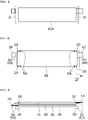
- Fig. 2 is a view showing a state in which the sealing member presses the electrode assembly according to an embodiment of the present disclosure.
- Fig. 3 is a side view of Fig. 2 .
- the battery cell includes an electrode assembly formed by sequentially stacking a first separator 100, a negative electrode plate 200, a second separator 300 and a positive electrode plate 400 having a rectangular shape, a negative electrode tab 210 formed to protrude from the negative electrode plate 200, and a positive electrode tab 410 formed to protrude from the positive electrode plate 400.
- the battery cell is a secondary battery and may be configured into a pouch-type secondary battery.
- a battery cell can be configured by a plurality of numbers, and the plurality of battery cells can be stacked together so as to be electrically connected to each other, thereby forming a battery cell stack.
- the battery cell may include an electrode lead protruding from the electrode assembly and a pouch case including the electrode assembly.
- the pouch case is for packaging the electrode assembly, and may be formed of a laminate sheet including a resin layer and a metal layer.
- the electrode assembly can be composed of a positive electrode plate, a negative electrode plate, and a separator. More specifically, as shown in Fig. 3 , the first separator 100, the negative electrode plate 200, the second separator 300, and the positive electrode plate 400 having a rectangular shape can be sequentially stacked to form an electrode assembly. At this time, the first separator 100 and the second separator 300 have larger size in all four surfaces than the negative electrode plate 200 and the positive electrode plate 400, and therefore, they can be adhered to each other to fix the position of the electrode assembly and the electrode tabs connected thereto.
- the first separator 100 and the second separator 300 are adhered by pressing with the sealing member 500 having a folded portion 520 in which the width at both ends is formed wider than the width at the central portion. Therefore, the first separator 100 and the second separator 300 can formed such that the whole of the tab edge portions 110 and 310 of the first and second separators 100 and 300 located on the surface on which the positive electrode tab 410 and the negative electrode tab 210 are formed, and a part of the both side edge portions 120 and 320 connected to the tab edge portions 110 and 310 are adhered to each other, whereby the inward adhesion width W1 at the tab edge portions 110 and 310 is about 2% to 50%, specifically 10% to 20% smaller than the inward adhesion width at both ends where the tab edge portions 110 and 310 and the both side edges portions 120 and 320 are connected.
- the sealing member 500 may be formed of a sealing bar.
- a heating means can be formed inside the sealing member 500.
- the separators is adhered by pressing the sealing member 500, and at the same time, the separators is heated via a heating means, so that the separators can be adhered to each other by heat fusion.
- the first separator 100 and the second separator 300 are adhered by pressing the formation portion of the negative electrode tab 210 and the positive electrode tab 410 by using a sealing member 500 having a folded portion 520 having a shape corresponding to the edge portion of the first separator 100 and the second separator 300 on which the negative electrode tab 210 and the positive electrode tab 410 are formed, whereby the pressing force through the sealing member 500 can be strongly applied even to the corner portion of the separator, thereby normally realizing the adhesion between the separators even at the corner portion, and preventing the folding phenomenon of the separators at the corner portion.
- the sealing member 500 is formed so that the adhesion portion of the first separator 100 and the second separator 300 does not interfere with the negative electrode plate 200 and the positive electrode plate 400.
- the first separator 100 and the second separator 300 are pressed so that they do not interfere with the positive electrode plate 200 and the positive electrode plate 400.
- the method of forming the adhesion portion of the first separator 100 and the second separator 300 so as not to interfere with the negative electrode plate 200 and the positive electrode plate 400 is most basically not shown in the drawings, but the size of the first separator 100 and the second separator 300 is made larger in four surfaces than the negative electrode plate 200 and the positive electrode plate 400, which can be carried out by an adhesion method using the sealing member 500 so as not to overlap even at any portion.
- the first separator 100 and the second separator 300 can be made larger than the negative electrode plate 200 and the positive electrode plate 400, or the region pressed and adhered by the sealing member 500 can be made smaller.
- a recessed portion 220 corresponding to the adhesive shape can be formed so that the negative electrode plate does not interfere with the portion where a part of the edges 120 and 320 on both side surfaces of the first separator 100 and the second separator 300 are adhered. Since the seal member 500 is formed so that the width at both ends is wider than the width at the central portion, and thus has a folded portion 520, interference occurs between the folded portion 520 of the sealing member 500 and the negative electrode plate 200 during the pressing of the first and second separators 100 and 300.
- the recessed portion 220 is pressed so as to correspond to the portion where the folded portion 520 presses and the four corner portions of the negative electrode plate 200 positioned, whereby even when the sealing member 500 presses the separators, the negative electrode plate 200 may not interfere with the pressed portion. Therefore, it is possible to prevent safety problems such as damage to the negative electrode plate 200 due to the pressing of the sealing member 500.
- the battery cells described above can be included in a battery module, and these battery modules can be included in a battery pack.
- the battery pack may have a structure in which one or more of the battery modules according to the embodiment of the present disclosure are gathered, and packed together with a battery management system (BMS) and a cooling device that control and manage battery's temperature, voltage, etc.
- BMS battery management system
- the battery pack can be applied to various devices.
- a device may be applied to a vehicle means such as an electric bicycle, an electric vehicle, or a hybrid vehicle, but the present disclosure is not limited thereto, and is applicable to various devices that can use a battery module, which also belongs to the scope of the present disclosure.
- a battery cell and a method for manufacturing the same according to an embodiment of the present disclosure provide an effect of preventing a folding phenomenon of the separator during an adhesion process between the separators, and adhering the separators so as not to occur interference with the electrode.
Landscapes
- Chemical & Material Sciences (AREA)
- Chemical Kinetics & Catalysis (AREA)
- Electrochemistry (AREA)
- General Chemical & Material Sciences (AREA)
- Engineering & Computer Science (AREA)
- Manufacturing & Machinery (AREA)
- Secondary Cells (AREA)
Abstract
Description
- This application claims the benefit of
Korean Patent Application No. 10-2020-0140347 filed on October 27, 2020 Korean Patent Application No. 10-2021-0117898 filed on September 3, 2021 - The present disclosure relates to a battery cell and a manufacturing method thereof, and more particularly to a battery cell that realizes sealing technologies and a manufacturing method thereof.
- Recently, as energy source price is increasing due to the depletion of fossil fuels and increasing interest is being paid to environmental pollution, the demand for environmentally-friendly alternative energy sources is bound to play an important role in the future life. Thus, research into techniques for generating various kinds of power, such as nuclear energy, solar energy, wind energy, and tidal power, is underway, and power storage apparatuses for more efficient use of the generated energy are also drawing much attention.
- In particular, as technology development and demands for mobile devices increase, the demand for batteries as energy sources is rapidly increasing, and accordingly, many researches on batteries capable of meeting diverse demands have been conducted.
- Typically, the demand for the lithium secondary battery, such as a lithium ion battery or a lithium ion polymer battery, which have advantages such as a high energy density, a discharge voltage, an output stability, and the like is high.
- Further, the secondary battery may be classified based on how the electrode assembly, having a structure in which a positive electrode, a negative electrode, and a separator interposed between the positive electrode and the negative electrode are stacked, is structured. Typically, the electrode assembly may include a jelly-roll (wound) type electrode assembly in which long sheet type positive electrodes and long sheet type negative electrodes are wound with a separator being interposed therebetween, and a stacked (laminated) type electrode assembly in which a plurality of positive electrodes and negative electrodes, cut into predetermined unit sizes, are sequentially stacked with separators being interposed therebetween, and the like.
- Further, the secondary battery is classified based on the shape of a battery case into a cylindrical battery having an electrode assembly mounted in a cylindrical case, a prismatic battery having an electrode assembly mounted in a prismatic case, and a pouch-shaped case having an electrode assembly mounted in a pouch-shaped case formed of an aluminum laminate sheet.
- In the case of a pouch-type battery cell, the electrode assembly stacked in the order of a separator, a negative electrode, a separator, and a positive electrode is inserted into the pouch case, and then the pouch case can be sealed together with an electrolytic solution, and adhesion between the separators may also be required.
-
Fig. 1 is a view showing an adhesion method between separators according to the related art. - Referring to
Fig. 1 , conventionally, in order to press the separator 20 interposed between the negative electrode plate and the positive electrode plate 10 and on one side thereof to adhere the separators to each other, an adhesion process between the separators was performed by pressing the separators using astraight sealing member 50 on the portion where the negative electrode tab and the positive electrode tab were formed. - However, since the sealing
member 50 herein is formed in a straight shape, a relatively weak adhesive force is acted on the corner portions of the separators corresponding to both end parts of the sealingmember 50, which may cause a folding phenomenon of the separators. Further, the portion where the sealing member is pressed during the sealing process and the portion where the negative electrode plate or the positive electrode plate is formed overlap with each other, whereby an interference phenomenon due to the pressing of the sealing member may occur on the negative electrode or the positive electrode is likely to occur. - It is an object of the present disclosure to provide a battery cell for preventing folding of the separator during the separator adhesion process, and a manufacturing method thereof.
- The objects of the present disclosure are not limited to the aforementioned objects, and other objects which are not described herein should be clearly understood by those skilled in the art from the following detailed description.
- In order to achieve the above object, according to one embodiment of the present disclosure, there is provided a battery cell comprising:
- an electrode assembly formed by sequentially stacking a first separator, a negative electrode plate, a second separator and a positive electrode plate having a rectangular shape;
- a negative electrode tab formed to protrude from the negative electrode plate; and
- a positive electrode tab formed to protrude from the positive electrode plate,
- wherein the first separator and the second separator have larger size in all four surfaces than the negative electrode plate and the positive electrode plate, and the whole of the tab edge portions of the first and second separators located on the surface on which the positive electrode tab and the negative electrode tab are formed and a part of the both side edge portions connected to the tab edge portion are adhered to each other, whereby the inward adhesion width at the tab edge portion is smaller than the inward adhesion width at both ends where the tab edge portion and the both side edges portions are connected. At this time, the inward adhesion width at the tab edge portion may be 2% to 50% smaller than the inward adhesion width at both ends where the tab edge portion and the both side edges portions are connected.
- The positive electrode plate and the negative electrode plate may not interfere with the adhered portions of the first and second separators. More specifically, a recessed portion corresponding to the adhesive shape may be formed at the four corners of the negative electrode plate, so that the negative electrode plate does not interfere with a portion to which a part of both side edge portions of the first and second separators are adhered.
- In order to achieve the above object, according to another embodiment of the present disclosure, there is provided a method for manufacturing a battery cell comprising the steps of:
- sequentially stacking a first separator, a negative electrode plate, a second separator and a positive electrode plate to form an electrode assembly; and
- pressing and sealing the first and second separators by using a sealing member having a folded portion in which the width at both ends is formed wider than the width at the central portion.
- Here, the sealing member may be formed of a sealing bar.
- More specifically, in the step of pressing and sealing the first and second separators using the sealing member, the sealing member may be formed in a shape corresponding to the edge portions of the first and second separators on which the positive electrode tab and the negative electrode tab are formed, so as to press the whole of the tab edge portions of the first and second separators located on the surface on which the positive electrode tab and the negative electrode tab are formed and a part of the both side edge portions connected to the tab edge portion
- Further, a heating means may be formed inside the sealing member.
- The sealing member may press the first and second separators so as not to interfere with the positive electrode plate and the negative electrode plate. The method may further include forming a recessed portion in the four corner portions of the negative electrode plate, before forming the electrode assembly. At this time, in the step of pressing and sealing the first and second separators using the sealing member, the folded portion of the sealing member may press the first and second separators so as to correspond to the recessed portion in the four corner portions of the negative electrode plate.
- According to yet another embodiment of the present disclosure, there is provided a battery module comprising the above-mentioned battery cell.
-
-
Fig. 1 is a view showing an adhesion method between separators according to the related art; -
Fig. 2 is a view showing a state in which the sealing member presses the electrode assembly according to an embodiment of the present disclosure; and -
Fig. 3 is a side view ofFig. 2 . - It should be appreciated that the exemplary embodiments, which will be described below, are illustratively described to help understand the present disclosure, and the present disclosure may be variously modified to be carried out differently from the exemplary embodiments described herein. However, in the description of the present disclosure, the specific descriptions and illustrations of publicly known functions or constituent elements will be omitted when it is determined that the specific descriptions and illustrations may unnecessarily obscure the subject matter of the present disclosure. In addition, in order to help understand the present disclosure, the accompanying drawings are not illustrated based on actual scales, but parts of the constituent elements may be exaggerated in size.
- As used herein, terms such as first, second, and the like may be used to describe various components, and the components are not limited by the terms. The terms are used only to discriminate one component from another component.
- Further, the terms used herein are used only to describe specific exemplary embodiments, and are not intended to limit the scope of the present disclosure. A singular expression includes a plural expression unless they have definitely opposite meanings in the context. It should be understood that the terms "comprise", "include", and "have" as used herein are intended to designate the presence of stated features, numbers, steps, constitutional elements, or combinations thereof, but it should be understood that they do not preclude a possibility of existence or addition of one or more other features, numbers, steps, constitutional elements, or combinations thereof.
- Now, the battery cell according to an embodiment of the present disclosure will be described with reference to
Figs. 2 and 3 . -
Fig. 2 is a view showing a state in which the sealing member presses the electrode assembly according to an embodiment of the present disclosure.Fig. 3 is a side view ofFig. 2 . - Referring to
Figs. 2 and 3 , the battery cell according to an embodiment of the present disclosure includes an electrode assembly formed by sequentially stacking afirst separator 100, anegative electrode plate 200, asecond separator 300 and apositive electrode plate 400 having a rectangular shape, anegative electrode tab 210 formed to protrude from thenegative electrode plate 200, and apositive electrode tab 410 formed to protrude from thepositive electrode plate 400. - The battery cell is a secondary battery and may be configured into a pouch-type secondary battery. Such a battery cell can be configured by a plurality of numbers, and the plurality of battery cells can be stacked together so as to be electrically connected to each other, thereby forming a battery cell stack. The battery cell may include an electrode lead protruding from the electrode assembly and a pouch case including the electrode assembly. The pouch case is for packaging the electrode assembly, and may be formed of a laminate sheet including a resin layer and a metal layer.
- According to the present embodiment, the electrode assembly can be composed of a positive electrode plate, a negative electrode plate, and a separator. More specifically, as shown in
Fig. 3 , thefirst separator 100, thenegative electrode plate 200, thesecond separator 300, and thepositive electrode plate 400 having a rectangular shape can be sequentially stacked to form an electrode assembly. At this time, thefirst separator 100 and thesecond separator 300 have larger size in all four surfaces than thenegative electrode plate 200 and thepositive electrode plate 400, and therefore, they can be adhered to each other to fix the position of the electrode assembly and the electrode tabs connected thereto. - According to the present embodiment, of the
first separator 100 and thesecond separator 300 are adhered by pressing with the sealingmember 500 having a foldedportion 520 in which the width at both ends is formed wider than the width at the central portion. Therefore, thefirst separator 100 and thesecond separator 300 can formed such that the whole of the tab edge portions 110 and 310 of the first andsecond separators positive electrode tab 410 and thenegative electrode tab 210 are formed, and a part of the both side edge portions 120 and 320 connected to the tab edge portions 110 and 310 are adhered to each other, whereby the inward adhesion width W1 at the tab edge portions 110 and 310 is about 2% to 50%, specifically 10% to 20% smaller than the inward adhesion width at both ends where the tab edge portions 110 and 310 and the both side edges portions 120 and 320 are connected. - At this time, the sealing
member 500 may be formed of a sealing bar. - Further, according to the present embodiment, a heating means can be formed inside the sealing
member 500. The separators is adhered by pressing the sealingmember 500, and at the same time, the separators is heated via a heating means, so that the separators can be adhered to each other by heat fusion. - Conventionally, for adhesion between separators, a separator adhesion process was performed in which the edge portions of the separators located at the portion where the electrode tabs are formed is pressed using a straight sealing member to adhere the separators. However, when the sealing member is formed in a straight shape to adhere only the tab corners of the separators, a relatively weak adhesive force is acted on the corner portions of the separators, which may cause a folding phenomenon of the separators.
- Thereby, according to the present embodiment, the
first separator 100 and thesecond separator 300 are adhered by pressing the formation portion of thenegative electrode tab 210 and thepositive electrode tab 410 by using a sealingmember 500 having a foldedportion 520 having a shape corresponding to the edge portion of thefirst separator 100 and thesecond separator 300 on which thenegative electrode tab 210 and thepositive electrode tab 410 are formed, whereby the pressing force through the sealingmember 500 can be strongly applied even to the corner portion of the separator, thereby normally realizing the adhesion between the separators even at the corner portion, and preventing the folding phenomenon of the separators at the corner portion. - Further, according to the present embodiment, the sealing
member 500 is formed so that the adhesion portion of thefirst separator 100 and thesecond separator 300 does not interfere with thenegative electrode plate 200 and thepositive electrode plate 400. Thefirst separator 100 and thesecond separator 300 are pressed so that they do not interfere with thepositive electrode plate 200 and thepositive electrode plate 400. - As described above, the method of forming the adhesion portion of the
first separator 100 and thesecond separator 300 so as not to interfere with thenegative electrode plate 200 and thepositive electrode plate 400 is most basically not shown in the drawings, but the size of thefirst separator 100 and thesecond separator 300 is made larger in four surfaces than thenegative electrode plate 200 and thepositive electrode plate 400, which can be carried out by an adhesion method using the sealingmember 500 so as not to overlap even at any portion. - In this case, the
first separator 100 and thesecond separator 300 can be made larger than thenegative electrode plate 200 and thepositive electrode plate 400, or the region pressed and adhered by the sealingmember 500 can be made smaller. - Alternatively, as shown in
Fig. 2 of the present disclosure, before the step of forming the electrode assembly, at the four corner portions of thenegative electrode plate 200 interposed between thefirst separator 100 and thesecond separator 300, a recessedportion 220 corresponding to the adhesive shape can be formed so that the negative electrode plate does not interfere with the portion where a part of the edges 120 and 320 on both side surfaces of thefirst separator 100 and thesecond separator 300 are adhered. Since theseal member 500 is formed so that the width at both ends is wider than the width at the central portion, and thus has a foldedportion 520, interference occurs between the foldedportion 520 of the sealingmember 500 and thenegative electrode plate 200 during the pressing of the first andsecond separators portion 220 is pressed so as to correspond to the portion where the foldedportion 520 presses and the four corner portions of thenegative electrode plate 200 positioned, whereby even when the sealingmember 500 presses the separators, thenegative electrode plate 200 may not interfere with the pressed portion. Therefore, it is possible to prevent safety problems such as damage to thenegative electrode plate 200 due to the pressing of the sealingmember 500. - The battery cells described above can be included in a battery module, and these battery modules can be included in a battery pack. The battery pack may have a structure in which one or more of the battery modules according to the embodiment of the present disclosure are gathered, and packed together with a battery management system (BMS) and a cooling device that control and manage battery's temperature, voltage, etc.
- The battery pack can be applied to various devices. Such a device may be applied to a vehicle means such as an electric bicycle, an electric vehicle, or a hybrid vehicle, but the present disclosure is not limited thereto, and is applicable to various devices that can use a battery module, which also belongs to the scope of the present disclosure.
- Although preferred embodiments of the present disclosure have been shown and described above, the scope of the present disclosure is not limited thereto, and numerous other modifications and embodiments can be devised by those skilled in the art that will fall within the spirit and scope of the principles of the invention described in the appended claims. Further, these modified embodiments should not be understood individually from the technical spirit or perspective of the present disclosure.
-
- 100:
- first separator
- 200:
- negative electrode plate
- 210:
- negative electrode tab
- 220:
- recessed portion
- 300:
- second separator
- 400:
- positive electrode plate
- 410:
- positive electrode tab
- 500:
- sealing member
- 510:
- main portion
- 520:
- two folded portions
- A battery cell and a method for manufacturing the same according to an embodiment of the present disclosure provide an effect of preventing a folding phenomenon of the separator during an adhesion process between the separators, and adhering the separators so as not to occur interference with the electrode.
- The effects of the present disclosure are not limited to the effects mentioned above and additional other effects not described above will be clearly understood from the description of the appended claims by those skilled in the art.
Claims (12)
- A battery cell comprising:an electrode assembly formed by sequentially stacking a first separator, a negative electrode plate, a second separator and a positive electrode plate having a rectangular shape;a negative electrode tab formed to protrude from the negative electrode plate; anda positive electrode tab formed to protrude from the positive electrode plate,wherein the first separator and the second separator have larger size in all four surfaces than the negative electrode plate and the positive electrode plate, and the whole of the tab edge portions of the first and second separators located on the surface on which the positive electrode tab and the negative electrode tab are formed and a part of the both side edge portions connected to the tab edge portion are adhered to each other, whereby the inward adhesion width at the tab edge portion is smaller than the inward adhesion width at both ends where the tab edge portion and the both side edges portions are connected.
- The battery cell according to claim 1, wherein:
the inward adhesion width at the tab edge portion is 2% to 50% smaller than the inward adhesion width at both ends where the tab edge portion and the both side edges portions are connected. - The battery cell according to claim 1, wherein:
the positive electrode plate and the negative electrode plate do not interfere with the adhered portions of the first and second separators. - The battery cell according to claim 1, wherein:
the positive electrode plate has larger size in all four surfaces than the negative electrode plate, and a recessed portion corresponding to the adhesive shape is formed at the four corners of the negative electrode plate, so that the negative electrode plate does not interfere with a portion to which a part of both side edge portions of the first and second separators are adhered. - A method for manufacturing a battery cell comprising the steps of:sequentially stacking a first separator, a negative electrode plate, a second separator and a positive electrode plate to form an electrode assembly; andpressing and sealing the first and second separators by using a sealing member having a folded portion in which the width at both ends is formed wider than the width at the central portion.
- The method for manufacturing a battery cell according to claim 5, wherein:
the sealing member is formed of a sealing bar. - The method for manufacturing a battery cell according to claim 5, wherein:in the step of pressing and sealing the first and second separators using the sealing member,the sealing member is formed in a shape corresponding to the edge portions of the first and second separators on which the positive electrode tab and the negative electrode tab are formed, so as to press the whole of the tab edge portions of the first and second separators located on the surface on which the positive electrode tab and the negative electrode tab are formed and a part of the both side edge portions connected to the tab edge portion
- The method for manufacturing a battery cell according to claim 5, wherein:
a heating means is formed inside the sealing member. - The method for manufacturing a battery cell according to claim 5, wherein:
the sealing member presses the first and second separators so as not to interfere with the positive electrode plate and the negative electrode plate. - The method for manufacturing a battery cell according to claim 5,
which further comprises forming a recessed portion in the four corner portions of the negative electrode plate, before forming the electrode assembly. - The method for manufacturing a battery cell according to claim 10,in the step of pressing and sealing the first and second separators using the sealing member,the folded portion of the sealing member presses the first and second separators so as to correspond to the recessed portion in the four corner portions of the negative electrode plate.
- A battery module comprising the battery cell according to claim 1.
Applications Claiming Priority (3)
| Application Number | Priority Date | Filing Date | Title |
|---|---|---|---|
| KR20200140347 | 2020-10-27 | ||
| KR1020210117898A KR20220056104A (en) | 2020-10-27 | 2021-09-03 | Battery cell and manufacturing method thereof |
| PCT/KR2021/012227 WO2022092549A1 (en) | 2020-10-27 | 2021-09-08 | Battery cell and method for manufacturing same |
Publications (2)
| Publication Number | Publication Date |
|---|---|
| EP4092793A1 true EP4092793A1 (en) | 2022-11-23 |
| EP4092793A4 EP4092793A4 (en) | 2023-09-20 |
Family
ID=81382864
Family Applications (1)
| Application Number | Title | Priority Date | Filing Date |
|---|---|---|---|
| EP21886546.7A Pending EP4092793A4 (en) | 2020-10-27 | 2021-09-08 | BATTERY CELL AND MANUFACTURING METHOD THEREFOR |
Country Status (4)
| Country | Link |
|---|---|
| US (1) | US20230275321A1 (en) |
| EP (1) | EP4092793A4 (en) |
| CN (1) | CN115398691B (en) |
| WO (1) | WO2022092549A1 (en) |
Family Cites Families (14)
| Publication number | Priority date | Publication date | Assignee | Title |
|---|---|---|---|---|
| JPH09213377A (en) * | 1996-01-30 | 1997-08-15 | Ricoh Co Ltd | Prismatic battery |
| JP3511443B2 (en) * | 1996-12-20 | 2004-03-29 | 株式会社リコー | Battery device |
| KR101014817B1 (en) * | 2007-12-14 | 2011-02-14 | 주식회사 엘지화학 | Stacked / Foldable Electrode Assembly with Safety Member and Method of Manufacturing the Same |
| DE102009013345A1 (en) * | 2009-03-16 | 2010-09-23 | Li-Tec Battery Gmbh | Electrode stack for a galvanic cell |
| KR101084909B1 (en) * | 2009-12-07 | 2011-11-17 | 삼성에스디아이 주식회사 | Electrode assembly block and its manufacturing method, secondary battery and its manufacturing method |
| JP5101655B2 (en) * | 2010-05-06 | 2012-12-19 | 三菱重工業株式会社 | battery |
| KR101182432B1 (en) * | 2010-11-15 | 2012-09-12 | 삼성에스디아이 주식회사 | Seperater sealing apparatus and manufacturing method using the same |
| JP2016038995A (en) * | 2014-08-06 | 2016-03-22 | 株式会社豊田自動織機 | Power storage device and method for manufacturing power storage device |
| KR102112670B1 (en) * | 2015-10-28 | 2020-05-19 | 주식회사 엘지화학 | Battery Cell of Venting Structure Using Taping |
| KR101950464B1 (en) * | 2015-11-30 | 2019-02-20 | 주식회사 엘지화학 | Battery Cell of Irregular Structure with Improved Sealing Reliability of Cell Case |
| KR101963313B1 (en) * | 2016-05-02 | 2019-03-28 | 주식회사 엘지화학 | Manufacturing method of secondary battery and manufacturing method of electrode assembly |
| JP6685983B2 (en) * | 2017-09-21 | 2020-04-22 | 株式会社東芝 | Electrode group, secondary battery, battery pack, and vehicle |
| KR102347901B1 (en) * | 2017-10-17 | 2022-01-06 | 주식회사 엘지에너지솔루션 | Pouch-Type Battery Case Having Structure to Prevent Crack and Method for Preparing the Same |
| KR102173032B1 (en) * | 2017-11-13 | 2020-11-02 | 주식회사 엘지화학 | Electrode assembly and manufacturing method for the same |
-
2021
- 2021-09-08 WO PCT/KR2021/012227 patent/WO2022092549A1/en not_active Ceased
- 2021-09-08 EP EP21886546.7A patent/EP4092793A4/en active Pending
- 2021-09-08 US US17/924,246 patent/US20230275321A1/en active Pending
- 2021-09-08 CN CN202180028909.6A patent/CN115398691B/en active Active
Also Published As
| Publication number | Publication date |
|---|---|
| CN115398691A (en) | 2022-11-25 |
| EP4092793A4 (en) | 2023-09-20 |
| WO2022092549A1 (en) | 2022-05-05 |
| US20230275321A1 (en) | 2023-08-31 |
| CN115398691B (en) | 2025-11-14 |
Similar Documents
| Publication | Publication Date | Title |
|---|---|---|
| EP2602840B1 (en) | Secondary battery pouch having improved stability, pouch-type secondary battery using same, and medium- or large-sized battery pack | |
| TWI713245B (en) | Battery cell of venting structure using taping, battery pack and device using the same | |
| US9299500B2 (en) | Power storage module | |
| US11158895B2 (en) | Battery module, battery pack including battery module, and vehicle including battery pack | |
| KR101328354B1 (en) | Lithium ion secondary battery, vehicle, and device equipped with battery | |
| US12463276B2 (en) | Pouch type secondary battery and battery module including the same | |
| US11302902B2 (en) | Method for manufacturing an electrode assembly for a battery cell and battery cell | |
| EP3731302B1 (en) | Battery module, battery pack comprising same battery module, and vehicle comprising same battery pack | |
| KR20140041057A (en) | Pouch-type secondary battery | |
| JP7222589B2 (en) | Battery modules and battery packs containing the same | |
| KR20170062845A (en) | Battery Module Comprising Unit Module Having Simple Structure | |
| EP3998217A1 (en) | Battery cell and battery module | |
| KR102792207B1 (en) | Battery module and method of manufacturing the same | |
| US20230275321A1 (en) | Battery Cell and Manufacturing Method Thereof | |
| EP4175020A1 (en) | Battery module and battery pack including same | |
| EP3582293B1 (en) | Battery cell and method for manufacturing electrode lead | |
| US20240097177A1 (en) | Electrode Assembly and Battery Cell Including the Same | |
| KR20170138305A (en) | Electrode Assembly Comprising Separator Having Sealed Edge Portion | |
| EP4187683A1 (en) | Battery module and manufacturing method thereof | |
| KR20220056104A (en) | Battery cell and manufacturing method thereof | |
| KR102006899B1 (en) | Method for Manufacturing Battery Pack Comprising Protect Assembly Having Safety Element for Protection against Overheating | |
| KR101735805B1 (en) | Battery Cell Comprising the Cell Case Having a Thermally-Welded Portion Bent | |
| KR20190112582A (en) | Battery cell cartridge having uniformity surface pressure | |
| KR20190112569A (en) | Unit battery module and battery module comprising the same | |
| KR20220041425A (en) | Battery cell and battery module including the same |
Legal Events
| Date | Code | Title | Description |
|---|---|---|---|
| STAA | Information on the status of an ep patent application or granted ep patent |
Free format text: STATUS: THE INTERNATIONAL PUBLICATION HAS BEEN MADE |
|
| PUAI | Public reference made under article 153(3) epc to a published international application that has entered the european phase |
Free format text: ORIGINAL CODE: 0009012 |
|
| STAA | Information on the status of an ep patent application or granted ep patent |
Free format text: STATUS: REQUEST FOR EXAMINATION WAS MADE |
|
| 17P | Request for examination filed |
Effective date: 20220819 |
|
| AK | Designated contracting states |
Kind code of ref document: A1 Designated state(s): AL AT BE BG CH CY CZ DE DK EE ES FI FR GB GR HR HU IE IS IT LI LT LU LV MC MK MT NL NO PL PT RO RS SE SI SK SM TR |
|
| REG | Reference to a national code |
Ref country code: DE Ref legal event code: R079 Free format text: PREVIOUS MAIN CLASS: H01M0010040000 Ipc: H01M0010052000 |
|
| A4 | Supplementary search report drawn up and despatched |
Effective date: 20230822 |
|
| RIC1 | Information provided on ipc code assigned before grant |
Ipc: H01M 50/586 20210101ALI20230816BHEP Ipc: H01M 50/531 20210101ALI20230816BHEP Ipc: H01M 50/46 20210101ALI20230816BHEP Ipc: H01M 10/0585 20100101ALI20230816BHEP Ipc: H01M 10/052 20100101AFI20230816BHEP |
|
| DAV | Request for validation of the european patent (deleted) | ||
| DAX | Request for extension of the european patent (deleted) | ||
| GRAP | Despatch of communication of intention to grant a patent |
Free format text: ORIGINAL CODE: EPIDOSNIGR1 |
|
| STAA | Information on the status of an ep patent application or granted ep patent |
Free format text: STATUS: GRANT OF PATENT IS INTENDED |
|
| GRAJ | Information related to disapproval of communication of intention to grant by the applicant or resumption of examination proceedings by the epo deleted |
Free format text: ORIGINAL CODE: EPIDOSDIGR1 |
|
| STAA | Information on the status of an ep patent application or granted ep patent |
Free format text: STATUS: REQUEST FOR EXAMINATION WAS MADE |
|
| INTG | Intention to grant announced |
Effective date: 20260220 |
|
| INTC | Intention to grant announced (deleted) | ||
| GRAP | Despatch of communication of intention to grant a patent |
Free format text: ORIGINAL CODE: EPIDOSNIGR1 |
|
| STAA | Information on the status of an ep patent application or granted ep patent |
Free format text: STATUS: GRANT OF PATENT IS INTENDED |