EP4092588A1 - Information processing apparatus, storage medium and information processing method - Google Patents
Information processing apparatus, storage medium and information processing method Download PDFInfo
- Publication number
- EP4092588A1 EP4092588A1 EP22174418.8A EP22174418A EP4092588A1 EP 4092588 A1 EP4092588 A1 EP 4092588A1 EP 22174418 A EP22174418 A EP 22174418A EP 4092588 A1 EP4092588 A1 EP 4092588A1
- Authority
- EP
- European Patent Office
- Prior art keywords
- scoring
- answer
- information
- determination region
- information processing
- Prior art date
- Legal status (The legal status is an assumption and is not a legal conclusion. Google has not performed a legal analysis and makes no representation as to the accuracy of the status listed.)
- Granted
Links
Images




Classifications
-
- G—PHYSICS
- G09—EDUCATION; CRYPTOGRAPHY; DISPLAY; ADVERTISING; SEALS
- G09B—EDUCATIONAL OR DEMONSTRATION APPLIANCES; APPLIANCES FOR TEACHING, OR COMMUNICATING WITH, THE BLIND, DEAF OR MUTE; MODELS; PLANETARIA; GLOBES; MAPS; DIAGRAMS
- G09B7/00—Electrically-operated teaching apparatus or devices working with questions and answers
-
- G—PHYSICS
- G06—COMPUTING OR CALCULATING; COUNTING
- G06Q—INFORMATION AND COMMUNICATION TECHNOLOGY [ICT] SPECIALLY ADAPTED FOR ADMINISTRATIVE, COMMERCIAL, FINANCIAL, MANAGERIAL OR SUPERVISORY PURPOSES; SYSTEMS OR METHODS SPECIALLY ADAPTED FOR ADMINISTRATIVE, COMMERCIAL, FINANCIAL, MANAGERIAL OR SUPERVISORY PURPOSES, NOT OTHERWISE PROVIDED FOR
- G06Q10/00—Administration; Management
-
- G—PHYSICS
- G09—EDUCATION; CRYPTOGRAPHY; DISPLAY; ADVERTISING; SEALS
- G09B—EDUCATIONAL OR DEMONSTRATION APPLIANCES; APPLIANCES FOR TEACHING, OR COMMUNICATING WITH, THE BLIND, DEAF OR MUTE; MODELS; PLANETARIA; GLOBES; MAPS; DIAGRAMS
- G09B7/00—Electrically-operated teaching apparatus or devices working with questions and answers
- G09B7/02—Electrically-operated teaching apparatus or devices working with questions and answers of the type wherein the student is expected to construct an answer to the question which is presented or wherein the machine gives an answer to the question presented by a student
-
- G—PHYSICS
- G06—COMPUTING OR CALCULATING; COUNTING
- G06F—ELECTRIC DIGITAL DATA PROCESSING
- G06F3/00—Input arrangements for transferring data to be processed into a form capable of being handled by the computer; Output arrangements for transferring data from processing unit to output unit, e.g. interface arrangements
- G06F3/01—Input arrangements or combined input and output arrangements for interaction between user and computer
- G06F3/048—Interaction techniques based on graphical user interfaces [GUI]
- G06F3/0481—Interaction techniques based on graphical user interfaces [GUI] based on specific properties of the displayed interaction object or a metaphor-based environment, e.g. interaction with desktop elements like windows or icons, or assisted by a cursor's changing behaviour or appearance
- G06F3/04817—Interaction techniques based on graphical user interfaces [GUI] based on specific properties of the displayed interaction object or a metaphor-based environment, e.g. interaction with desktop elements like windows or icons, or assisted by a cursor's changing behaviour or appearance using icons
-
- G—PHYSICS
- G06—COMPUTING OR CALCULATING; COUNTING
- G06F—ELECTRIC DIGITAL DATA PROCESSING
- G06F3/00—Input arrangements for transferring data to be processed into a form capable of being handled by the computer; Output arrangements for transferring data from processing unit to output unit, e.g. interface arrangements
- G06F3/01—Input arrangements or combined input and output arrangements for interaction between user and computer
- G06F3/048—Interaction techniques based on graphical user interfaces [GUI]
- G06F3/0481—Interaction techniques based on graphical user interfaces [GUI] based on specific properties of the displayed interaction object or a metaphor-based environment, e.g. interaction with desktop elements like windows or icons, or assisted by a cursor's changing behaviour or appearance
- G06F3/0482—Interaction with lists of selectable items, e.g. menus
-
- G—PHYSICS
- G06—COMPUTING OR CALCULATING; COUNTING
- G06F—ELECTRIC DIGITAL DATA PROCESSING
- G06F3/00—Input arrangements for transferring data to be processed into a form capable of being handled by the computer; Output arrangements for transferring data from processing unit to output unit, e.g. interface arrangements
- G06F3/01—Input arrangements or combined input and output arrangements for interaction between user and computer
- G06F3/048—Interaction techniques based on graphical user interfaces [GUI]
- G06F3/0484—Interaction techniques based on graphical user interfaces [GUI] for the control of specific functions or operations, e.g. selecting or manipulating an object, an image or a displayed text element, setting a parameter value or selecting a range
- G06F3/04845—Interaction techniques based on graphical user interfaces [GUI] for the control of specific functions or operations, e.g. selecting or manipulating an object, an image or a displayed text element, setting a parameter value or selecting a range for image manipulation, e.g. dragging, rotation, expansion or change of colour
-
- G—PHYSICS
- G06—COMPUTING OR CALCULATING; COUNTING
- G06T—IMAGE DATA PROCESSING OR GENERATION, IN GENERAL
- G06T11/00—Two-dimensional [2D] image generation
- G06T11/20—Drawing from basic elements
- G06T11/23—Drawing from basic elements using straight lines or curves
-
- G—PHYSICS
- G06—COMPUTING OR CALCULATING; COUNTING
- G06T—IMAGE DATA PROCESSING OR GENERATION, IN GENERAL
- G06T11/00—Two-dimensional [2D] image generation
- G06T11/20—Drawing from basic elements
- G06T11/26—Drawing of charts or graphs
Definitions
- the present disclosure relates to an information processing apparatus, a storage medium and an information processing method.
- a scoring criterion(s) representing a correct answer range, in which answers are determined to be correct needs to be set in advance so that answer figures approximate to a model answer are determined to be correct. If, in setting such a scoring criterion(s), a conventional method of specifying a range on a coordinate plane by a user specifying numerical values is used, an error is likely to occur, and also it is troublesome.
- an information processing apparatus including:
- a non-transitory computer-readable storage medium storing a program that causes a processor of an information processing apparatus to generate scoring criterion information that is referenced in a scoring process of an answer figure to a problem that requires drawing of a figure in a Cartesian coordinate system that is a coordinate plane or a coordinate space, wherein in response to a reference figure being drawn in the Cartesian coordinate system based on a user operation, the Cartesian coordinate system being displayed on a display, the scoring criterion information including information on a scoring criterion determined based on the reference figure is generated.
- an information processing method that is performed by a computer, including:
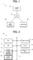
- FIG. 1 is a schematic configuration diagram of a scoring system 1 according to an embodiment(s).
- the scoring system 1 includes a scoring server 10 (information processing apparatus), a client terminal 20 and a client server 30.
- the scoring server 10, the client terminal 20 and the client server 30 are connected to one another via a communication network N to perform information communications.
- the communication network N is, for example, the Internet, but not limited thereto and may be another network, such as a LAN (Local Area Network).
- the scoring system 1 is a computer system that provides automatic scoring services in CBT.
- the scoring system 1 of this embodiment can perform automatic scoring of answers to problems (questions) that each require drawing of a figure(s) in a Cartesian coordinate system that is a coordinate plane.
- the scoring system 1 may also be able to perform automatic scoring of answers to problems in other formats (e.g., problem that requires selection of a correct answer from multiple choices, problem that requires input of a numerical value as an answer, etc.).
- the scoring server 10 of the scoring system 1 In response to a request from the client terminal 20, the scoring server 10 of the scoring system 1 generates scoring criterion data 332 (scoring criterion information) (shown in FIG.
- scoring server 10 determines a score of an answer figure to a problem and sends scoring result data 335 including information on a scoring result to the client server 30 (scoring process).
- scoring server 10 references the scoring criterion included in the scoring criterion data 332. Details of these processes will be described later.
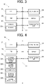
- FIG. 2 is a block diagram showing a functional configuration of the scoring server 10.
- the scoring server 10 includes a CPU (Central Processing Unit) 11, a RAM (Random Access Memory) 12, a storage 13, an operation unit 14, a display 15, a communication unit 16 and a bus 17.
- the components of the scoring server 10 are connected to one another via the bus 17.
- the CPU 11 is a processor that controls operation of the components of the scoring server 10.
- the CPU 11 reads a scoring criterion generation program 131, a scoring program 132 or the like among various programs stored in the storage 13, loads the read program to a work area of the RAM 12, and performs a process among various processes in accordance with the loaded program.
- the CPU 11 executes the scoring criterion generation program 131 to provide the client terminal 20 with a UI (User Interface) for generating scoring criteria, and also generate scoring criterion data 332 based on user operations at the client terminal 20 and send it to the client server 30.
- UI User Interface
- the scoring server 10 may have two or more processors (e.g., two or more CPUs), and these processors may perform processes that the CPU 11 of this embodiment performs. In this case, the processors may be involved in each process, or may independently perform different processes in parallel.
- the RAM 12 provides the CPU 11 with a memory space for working, and stores temporary data.
- the RAM 12 may include a nonvolatile memory.
- the storage 13 is a non-transitory computer-readable storage medium that stores programs, data and so forth readable by the CPU 11 as a computer, and is configured by an HDD (Hard Disk Drive), an SSD (Solid State Drive) or the like.
- the storage 13 stores programs that are executed by the CPU 11, such as the scoring criterion generation program 131 and the scoring program 132, data that is referenced in execution of the programs, and so forth.
- the programs are stored in the storage 13 in the form of computer-readable program codes.
- the operation unit 14 includes a pointing device, such as a mouse, and a keyboard, and receives user's point inputs, key inputs and so forth, and outputs information on these operations to the CPU 11.
- a pointing device such as a mouse
- a keyboard receives user's point inputs, key inputs and so forth, and outputs information on these operations to the CPU 11.
- the display 15 includes a display device, such as a liquid crystal display, and displays various kinds of information on the display device in accordance with display control signals from the CPU 11.
- a display device such as a liquid crystal display
- the communication unit 16 includes a router and a network card. Via the communication unit 16, the CPU 11 sends and receives data to and from the client terminal 20 and the client server 30 on the communication network N by communication connection therewith.
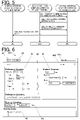
- FIG. 3 is a block diagram showing a functional configuration of the client terminal 20.
- the client terminal 20 is a computer device that is used by a user who uses services of the scoring system 1 (e.g., teacher who manages student answers and scoring results thereof).
- the client terminal 20 is, for example, a laptop PC (Personal Computer), a desktop PC, a tablet terminal, a smartphone or the like.
- the client terminal 20 requests, on a browser 231, the scoring server 10 and the client server 30 to perform various processes in accordance with input operations made by the user, and displays, on a display 25, process results sent from the scoring server 10 and so forth.
- the client terminal 20 includes a CPU 21, a RAM 22, a storage 23, an operation unit 24, a display 25, a communication unit 26 and a bus 27.
- the components of the client terminal 20 are connected to one another via the bus 27.
- the CPU 21 is a processor that controls operation of the components of the client terminal 20.
- the CPU 21 reads a program, such as the browser 231, among various programs stored in the storage 23, loads the read program to a work area of the RAM 22, and performs a process among various processes in accordance with the loaded program.
- the RAM 22 provides the CPU 21 with a memory space for working, and stores temporary data.
- the RAM 22 may include a nonvolatile memory.
- the storage 23 is a non-transitory computer-readable storage medium that stores programs, data and so forth readable by the CPU 21 as a computer, and is configured by an HDD, an SSD or the like.
- the storage 23 stores programs that are executed by the CPU 21, such as the browser 231, data that is referenced in execution of the programs, and so forth.
- the programs are stored in the storage 23 in the form of computer-readable program codes.
- the browser 231 is a program to display, on the display 25, execution results of various programs sent from the scoring server 10 and the client server 30, information on web pages on the Internet, and so forth.
- the operation unit 24, the display 25 and the communication unit 26 are respectively the same as the operation unit 14, the display 15 and the communication unit 16 of the scoring server 10 in configuration, and hence their descriptions will be omitted.
- FIG. 4 is a block diagram showing a functional configuration of the client server 30.
- the client server 30 is a computer device that stores data (e.g., scoring criterion data for each problem, answer data, scoring result data, etc.) managed by the user who uses services of the scoring system 1, and also stores and executes an automatic scoring script(s) generated by the user.
- data e.g., scoring criterion data for each problem, answer data, scoring result data, etc.
- the client server 30 includes a CPU 31, a RAM 32, a storage 33, an operation unit 34, a display 35, a communication unit 36 and a bus 37.
- the components of the client server 30 are connected to one another via the bus 37.
- the CPU 31 is a processor that controls operation of the components of the client server 30.
- the CPU 31 reads a program, such as an automatic scoring script 331, among various programs stored in the storage 33, loads the read program to a work area of the RAM 32, and performs a process among various processes in accordance with the loaded program.
- the CPU 31 executes the automatic scoring script 331 to call the automatic scoring API of the scoring server 10 with individual data for scoring 334 as arguments, thereby causing the scoring server 10 to generate scoring result data 335, and obtains the scoring result data 335.
- programs include scripts that are executable without being compiled.
- the RAM 32 provides the CPU 31 with a memory space for working, and stores temporary data.
- the RAM 32 may include a nonvolatile memory.
- the storage 33 is a non-transitory computer-readable storage medium that stores programs, data and so forth readable by the CPU 31 as a computer, and is configured by an HDD, an SSD or the like.
- the storage 33 stores programs that are executed by the CPU 31, such as the automatic scoring script 331, data that is referenced in execution of the programs, and so forth.
- the programs are stored in the storage 33 in the form of computer-readable program codes.
- the automatic scoring script 331 is usually created by the user of the scoring system 1 for a purpose, but a pre-created one may be used.
- Examples of the data stored in the storage 33 include scoring criterion data 332, answer data 333 (answer information), individual data for scoring 334 and scoring result data 335.
- the scoring criterion data 332 is referenced in the scoring process of an answer figure to a problem that requires drawing of a figure in a Cartesian coordinate system that is a coordinate plane.
- the scoring criterion data 332 includes information on a scoring criterion(s) that is used in the scoring process.
- the scoring criterion data 332 is generated by the scoring server 10 in response to a request from the client terminal 20, and sent to the client server 30 and stored in the storage 33.
- the scoring criterion data 332 is a file in a format referenceable as arguments in execution of the automatic scoring API of the scoring server 10, a file in json format in this embodiment.
- the answer data 333 is data of an answer figure generated by an answerer who tackles a problem, such as a student, with a not-shown terminal device for answering. If there are two or more answerers, the answer data 333 is generated by/for each answerer. Data items included in the answer data 333 are predetermined for each problem.
- the individual data for scoring 334 is data made of the answer data 333 of an answerer (individual) inserted into the scoring criterion data 332. Hence, the individual data for scoring 334 includes the scoring criterion information and the answer information generated by one answerer. If there are two or more answerers, the individual data for scoring 334 is generated for each answerer.
- the individual data for scoring 334 is a file in the same format as the scoring criterion data 332, the json format in this embodiment.
- the scoring result data 335 includes information on a scoring result of an answer.
- the scoring result data 335 is generated by the scoring server 10 with the automatic scoring API called with the individual data for scoring 334 as arguments, and sent to the client server 30.
- the operation unit 34, the display 35 and the communication unit 36 are respectively the same as the operation unit 14, the display 15 and the communication unit 16 of the scoring server 10 in configuration, and hence their descriptions will be omitted.
- the scoring system 1 focusing on operation to generate a scoring criterion(s) and operation to determine a score of an answer using the scoring criterion.
- the main agents of these operations are the CPU 11 of the scoring server 10, the CPU 21 of the client terminal 20 and the CPU 31 of the client server 30, hereinafter the scoring server 10, the client terminal 20 and the client server 30 may be referred to as the main agents for the sake of convenience.
- FIG. 5 is a sequence diagram to explain the scoring criterion generation process.
- FIG. 5 shows flow of signals that are sent and received between the scoring server 10, the client terminal 20 and the client server 30 in the scoring criterion generation process.
- a user who uses a function of automatic scoring provided by the scoring system 1 starts the browser 231 at the client terminal 20, and accesses a predetermined URL.
- the client terminal 20 requests the scoring server 10 to send display data for displaying a scoring criterion setting screen 251 (Step S101).
- the scoring server 10 executes the scoring criterion generation program 131, and sends the display data for displaying the scoring criterion setting screen 251 to the client terminal 20 to cause the client terminal 20 to display the scoring criterion setting screen 251 on the display 25 (Step S102).
- FIG. 6 shows an example of the scoring criterion setting screen 251.
- scoring criterion setting screen 251 On the scoring criterion setting screen 251, reference/correct answer information 41, reference geometry information 42, answer figure information 43, scoring variable information 44, scoring logic information 45, a question ID 461, a subsidiary question ID 462, a save button 47, a reference figure drawing button 48 and so forth are displayed.
- a point having "a" as x-coordinate and "b" as y-coordinate on an x-y coordinate plane that is used for answering a problem is referred to as a point (a, b).
- the reference/correct answer information 41 is information on a correct figure set by the user as a model answer to a problem.
- a straight line L0 having Point 0 (5, 10) and Point 1 (-5, -10) as two endpoints is set as a correct figure.
- the setting "Bind by index” means that scoring is carried out by taking the answering order of multiple answer elements provided after this setting into account.
- a point selected first in answering by an answerer is treated as Point 0
- a point selected second in answering by the answerer is treated as Point 1.
- scoring is carried out without taking the answering order into account.
- the two points selected first and second are treated as "Point 0, Point 1" and "Point 1, Point 0", and both combinations are subjected to scoring. The one having a higher score is adopted as a scoring result.
- the reference geometry information 42 is information on geometries that are referenced in the scoring process.
- "graphBounds" representing a coordinate plane that is used for answering is set.
- the "graphBounds” in this embodiment is a rectangular region (square region, to be more specific) having a length in x-direction of 20 and a length in y-direction of 20 with a point (-10, -10) as the lower left end.
- the "graphBounds" is set, but two or more reference geometries may be set.
- the answer figure information 43 is data on an answerer's answer figure. At the stage where scoring criteria are set, dummy answer figure information 43 is input for providing parts into which an answerer's answer data is to be inserted. In this embodiment, coordinate data of the two endpoints P0 (Point 0), P1 (Point 1) of the straight line L0 as an answer figure is input to correspond to the reference/correct answer information 41.
- the scoring variable information 44 is information on scoring variables to construct scoring logic in the scoring logic information 45.
- a value of the automatic scoring function "equalsAll” is assigned to the scoring variable "correct”.
- the automatic scoring function "equalsAll” is a function to return "true (1)” if data of the reference/correct answer information 41 (in this embodiment, coordinates of Point 0 and Point 1) and data of the answer figure information 43 (same as the above, i.e., coordinates of Point 0 and Point 1) exactly match, and returns "false (0)" if they do not exactly match.
- one scoring variable is used, but two or more scoring variables may be set.
- the scoring logic information 45 is information on the scoring logic using the scoring variable(s) in the scoring variable information 44.
- the data of the reference/correct answer information 41 and the data of the answer figure information 43 do not exactly match, so that the scoring variable "correct” is "false (0)", and the score is "0".
- the question ID 461 is a unique code assigned to a question (problem).
- the question ID 461 can call the scoring criterion data 332 for the problem.
- the subsidiary question ID 462 is a unique code assigned to a subsidiary question (subsidiary problem) included in a problem. If a problem includes two or more subsidiary problems, the scoring criterion data 332 for the problem includes information on two or more sets of scoring criteria for the respective subsidiary problems. In this case, scoring can be carried out, for example, by a method of adding up scores of subsidiary problems of a problem to be the total score of the problem or a method of determining that a problem is correctly answered if all subsidiary problems of the problem are correctly answered.
- the save button 47 is a button for generating scoring criterion data 332 with the contents of the scoring criterion setting screen 251 at the time.
- the reference figure drawing button 48 is a button that is selected to draw, on a graph viewer, reference figures that are used for setting scoring criteria. A method for setting scoring criteria using reference figures will be described later.
- the client terminal 20 sends a request to the scoring server 10 to generate scoring criterion data 332 (Step S103 in FIG. 5 ).
- the scoring server 10 that has received the request performs a process in accordance with the scoring criterion generation program 131, generates scoring criterion data 332 in the json format and sends it to the client server 30 (Step S104).
- the scoring criterion data 332 is stored in the storage 33 of the client server 30 in Step S104, the scoring criterion generation process ends.
- FIG. 7 shows examples of contents of scoring criterion data 332.
- FIG. 7 shows the scoring criterion data 332 reflecting the contents of the scoring criterion setting screen 251 shown in FIG. 6 .
- the scoring criterion data 332 includes a subsidiary question ID, scoring logic, a correct answer (contents of the reference/correct answer information 41), an answerer's answer (contents of the answer figure information 43) and an answerer ID to identify an answerer.
- the scoring criterion data 332 shown in FIG. 7 is merely an example and hence is not limited to the format shown therein.
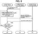
- FIG. 8 is a sequence diagram to explain the scoring process.
- the scoring process is started by a predetermined user operation at the client terminal 20 in a state in which scoring criterion data 332 and answer data 333 are stored in the storage 33 of the client server 30.
- the client terminal 20 requests the client server 30 to start the automatic scoring script 331 (Step S201).
- the client server 30 executes the automatic scoring script 331.
- the client server 30 first inserts one answer data 333 into the scoring criterion data 332 to generate individual data for scoring 334, and stores it in the storage 33 (Step S202).
- Step S202 the client server 30 generates the individual data for scoring 334 by replacing the "Answerer's Answer" in the scoring criterion data 332 shown in FIG. 7 with the contents of the actual answer of an answerer. In this manner, the client server 30 generates the individual data for scoring 334 that includes the information on the scoring criterion included in the scoring criterion data 332 and the answer data 333 of an answerer.
- the client server 30 calls the automatic scoring API of the scoring server 10 with the individual data for scoring 334 generated in Step S202 as arguments (Step S203).
- the scoring server 10 executes the scoring program 132, generates scoring result data 335 and sends it to the client server 30 (Step S204).
- the scoring server 10 determines a score of the answer data 333 included in the received individual data for scoring 334, referencing the scoring criterion of the scoring criterion data 332 included in the individual data for scoring 334. In the case shown in FIG. 6 and FIG.
- the client server 30 determines whether scoring has finished for all answerers (Step S205). If the client server 30 determines that there is at least one answerer for whom scoring has not finished yet (Step S205; "NO"), the client server 30 performs Step S202 again with the answer data 333 of the next answerer. If the client server 30 determines that scoring has finished for all answerers (Step S205; "YES"), the client server 30 exits the automatic scoring script 331. Thus, the scoring process ends.
- scoring system 1 of this embodiment in order to set scoring criteria with the scoring criterion setting screen 251, it is possible to display (draw) reference figures on the display 25 of the client terminal 20 and reflect information on the reference figures in the scoring criteria.
- first to fifth examples of the method for setting scoring criteria with reference figures will be described.
- determination regions are defined by reference figures, and a scoring criterion about a positional relationship between the determination regions and an answer figure is set.
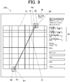
- FIG. 9 shows a reference figure setting screen 252 according to the first example.
- the reference figure setting screen 252 is the graph viewer displayed on the display 25 when the reference figure drawing button 48 is selected on the scoring criterion setting screen 251.
- a coordinate plane 51 Cartesian coordinate system
- a mode selection button 52 On the reference figure setting screen 252, a reference line 61, reference rectangles 62, an answer figure 71 and so forth are displayed.
- the reference line 61 and the reference rectangles 62 are examples of reference figures.
- the coordinate plane 51 corresponds to the "graphBounds" set in the reference geometry information 42 on the scoring criterion setting screen 251.
- the reference line 61, the reference rectangles 62 and the answer figure 71 are drawn, for example.
- the coordinate ranges (x-range, y-range) and grid spacing(s) (x grid spacing, y grid spacing) of the coordinate plane 51 can be changed by inputting numerical values in text boxes 53 provided at the right side on the reference figure setting screen 252. This change is reflected in the contents of the "graphBounds" in the reference geometry information 42 on the scoring criterion setting screen 251.
- reference values can be displayed on the x axis and/or the y axis of the coordinate plane 51 in accordance with to user operations. For example, "0" representing the origin can be displayed at the intersection of the x axis and the y axis.
- the mode selection button 52 is a button for specifying a mode for drawing reference figures on the reference figure setting screen 252.
- a not-shown group of icons representing multiple drawing mode choices is displayed, and the current drawing mode can be changed to another by selecting an icon from the icons.
- the drawing modes include a line drawing mode for drawing reference lines as reference figures, a region specifying mode for specifying regions based on reference lines, and a rectangle drawing mode for drawing reference rectangles as reference figures.
- the reference line 61 corresponds to the straight line L0 (correct figure set by the user as a model answer to a problem) set in the reference/correct answer information 41 on the scoring criterion setting screen 251.
- the reference line 61 can be generated by selecting the line drawing mode with the mode selection button 52, and making an operation(s) to specify two endpoints on the coordinate plane 51 (e.g., operations of putting a mouse cursor on desired points and clicking).
- the snap technique may be employed that limits selectable points to integer coordinates.
- the shape of the reference line 61 may be changed by an operation(s) to change the position(s) of the endpoint(s) of the reference line 61, and this change may be reflected in the reference/correct answer information 41 on the scoring criterion setting screen 251.
- this change may be reflected in the reference line 61 on the reference figure setting screen 252.
- the reference rectangles 62 are rectangles having sides parallel to the coordinate axes of the coordinate plane 51.
- the reference rectangles 62 shown in FIG. 9 are squares having a length of each side of 2 with the two endpoints of the reference line 61 as their respective centers.
- the reference rectangles 62 represent boundaries respectively defining determination regions R0, R1.
- the positional relationship between these determination regions R0, R1 and the answer figure 71 can be set as a scoring criterion.
- the scoring criterion can be set such that the answer figure 71 is determined to be correct if it is partly in each of the determination regions R0, R1.
- the scoring criterion may be set such that the answer figure 71 having predetermined feature points (two endpoints P0, P1) respectively located in the determination regions R0, R1 is determined to be correct.
- the reference rectangles 62 are drawn on the coordinate plane 51 in accordance with user operations in a state in which the rectangle drawing mode is selected with the mode selection button 52.
- the user operations are, for example, operations to specify positions of opposite vertices of the reference rectangles 62 on the coordinate plane 51.
- the CPU 11 identifies the positions of the reference rectangles 62 on the coordinate plane 51.
- the user operations may be drag operations. In this case, the CPU 11 identifies the start point and the end point of each drag operation as the positions of opposite vertices of each reference rectangle 62.
- the snap technique may be employed that limits selectable points to integer coordinates.
- the answer figure 71 corresponds to the straight line L0 in the answer figure information 43 on the scoring criterion setting screen 251. At the stage where criteria are generated, the answer figure 71 is a dummy.
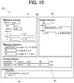
- FIG. 10 shows an example of the scoring criterion setting screen 251 reflecting the contents of the reference figure setting screen 252 shown in FIG. 9 .
- the "graphBounds” representing a coordinate region for answering and the determination regions "R0", “R1” corresponding to the two reference rectangles 62 are defined and displayed.
- the coordinate data or the like representing the determination regions "R0", “R1” in the reference geometry information 42 is calculated by the CPU 11 from the contents of the determination regions R0, R1 on the reference figure setting screen 252 and displayed. This eliminates the need for the user to input coordinate data of the determination regions "R0", “R1” as reference geometries and accordingly saves user time and effort.
- the scoring variables "satisfied_0" and “satisfied_1” are defined and displayed.
- a value of the automatic scoring function "lineHits” with the straight line “L0” in the answer figure information 43 and the determination region “R0”, which is a reference geometry, as arguments is assigned.
- a value of the automatic scoring function "lineHits” with the straight line “L0” in the answer figure information 43 and the determination region “R1”, which is a reference geometry, as arguments is assigned.
- the automatic scoring function "lineHits” is a function to return "true” if a straight line as an argument is partly in a determination region as an argument.
- the scoring logic is defined to make the “score” “1” if the scoring variables "satisfied_0" and “satisfied_1” are both "true".
- the straight line L0 (answer figure 71) in the answer figure information 43 is partly in each of the determination regions R0, R1, so that the "score” calculated is "1".
- the scoring criterion data 332 generated with the scoring criterion setting screen 251 shown in FIG. 10 is used in the scoring process to determine whether the answer figure 71 is partly in each of the determination regions R0, R1.
- FIG. 11 shows another example of the scoring criterion setting screen 251 reflecting the contents of the reference figure setting screen 252 shown in FIG. 9 .
- the scoring variables "in1”, “in2” and “correct” are defined and displayed.
- a value of the automatic scoring function "inBox” with “L0.points[0]” representing one endpoint P0 of the straight line L0 in the answer figure information 43 and the determination region “R0” as arguments is assigned.
- a value of the automatic scoring function "inBox” with "L0.points[1]” representing the other endpoint P1 of the straight line L0 in the answer figure information 43 and the determination region “R1" as arguments is assigned.
- the automatic scoring function "inBox” is a function to return “true” if a point as an argument is located in a determination region as an argument.
- the scoring variable “correct” is defined to be “true” if the scoring variables "in1" and “in2" are both “true”.
- the scoring logic information 45 determines a score.
- the endpoints P0, P1 of the straight line L0 (answer figure 71) in the answer figure information 43 are respectively located in the determination regions R0, R1, so that the scoring variables "in1", “in2” and “correct” are all "true (1)", and the "score” calculated is "1".
- the scoring criterion data 332 generated with the scoring criterion setting screen 251 shown in FIG. 11 is used in the scoring process to determine whether predetermined feature points (two endpoints P0, P1 in the first example) of the answer figure 71 are respectively located in the determination regions R0, R1.
- the definitions of the scoring variables in the scoring variable information 44 and the contents of the scoring logic in the scoring logic information 45 can be freely set by the user in accordance with a desired scoring method.
- the reference rectangles 62 as reference figures respectively define the determination regions R0, R1.
- two or more reference lines as reference figures may define a determination region (R4), serving as its boundary.
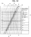
- FIG. 12 shows the reference figure setting screen 252 according to a second example.
- reference lines 63, 64 are displayed.
- the reference lines 63, 64 are examples of reference figures.
- a region with the reference line 63 as its boundary and the y-coordinate being equal to or smaller than that of the reference line 63 is a determination region R2
- a region with the reference line 64 as its boundary and the y-coordinate being equal to larger than that of the reference line 64 is a determination region R3.
- the determination region R2 is a region satisfying y ⁇ 2x + 2
- the determination region R3 is a region satisfying y ⁇ 2x - 2.
- the overlap area of the determination regions R2, R3 is referred to as a determination region R4.
- the determination regions R2, R3 shown in FIG. 12 are set by the following procedure.
- the region specifying mode is selected with the mode selection button 52, and the reference line 63 is drawn.
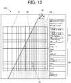
- the reference line 63 can be drawn by a user operation(s) to specify two points on the coordinate plane 51. From this state, a user operation (mouse over operation) is made to put a cursor 55 on one side or the other side of the reference line 63 on the display screen (reference figure setting screen 252), so that the one side or the other side of the reference line 63 can be specified as the determination region R2.
- a user operation mouse over operation
- the cursor 55 is put on the side having the y-coordinate smaller (x-coordinate larger) than that of the reference line 63, so that the determination region R2 is specified.
- the contents of the specified determination region R2 are reflected in an information display section 54 provided at the right side on the reference figure setting screen 252. If the contents input in the text boxes of the information display section 54 are changed, this change may be reflected in the reference line 63 and the determination region R2.
- a confirmation operation such as a click operation, is made in the state shown in FIG. 13 , the reference line 63 and the determination region R2 are fixed and reflected in the reference geometry information 42 on the scoring criterion setting screen 251.
- the user operation to specify the determination region R2 may be an operation other than the mouse over operation.
- the reference line 64 is drawn, and the cursor 55 is put on the side having the y-coordinate larger (x-coordinate smaller) than that of the reference line 64, so that the determination region R3 is specified.
- the reference line 64 and the determination region R3 are fixed.
- the determination region R4 which is the overlap area of the determination regions R2, R3, is fixed.
- FIG. 15 shows an example of the scoring criterion setting screen 251 reflecting the contents of the reference figure setting screen 252 shown in FIG. 14 .
- the "graphBounds" representing a coordinate region for answering and the determination regions "R2", “R3” shown in FIG. 12 to FIG. 14 are defined and displayed.
- the inequalities representing the determination regions "R2", “R3” in the reference geometry information 42 are respectively calculated by the CPU 11 from the contents of the reference lines 63, 64 and the determination regions R2, R3 on the reference figure setting screen 252 and displayed. This eliminates the need for the user to input data for the CPU 11 to identify the determination regions R2, R3 as reference geometries and accordingly saves user time and effort.
- the scoring variables "sati_pt0R2”, “sati_pt0R3”, “sati_pt1R2” and “sati_pt1R3” are defined and displayed.
- a value of the automatic scoring function "satisfies” with "L0.pt0” representing one endpoint P0 of the straight line L0 in the answer figure information 43 and the determination region "R2" as arguments is assigned.
- a value of the automatic scoring function "satisfies" with "L0.pt0" representing one endpoint P0 of the straight line L0 in the answer figure information 43 and the determination region "R3" as arguments is assigned.
- a value of the automatic scoring function "satisfies” with “L0.pt1” representing the other endpoint P1 of the straight line L0 in the answer figure information 43 and the determination region “R2" as arguments is assigned.
- a value of the automatic scoring function "satisfies” with "L0.pt1” representing the other endpoint P1 of the straight line L0 in the answer figure information 43 and the determination region "R3” as arguments is assigned.
- the automatic scoring function "satisfies” is a function to return "true” if a point as an argument is located in a determination region as an argument.
- the scoring logic is defined to make the “score” "1” if the scoring variables "sati_pt0R2", “sati_pt0R3", “sati_pt1R2” and “sati_pt1R3” are all “true”.
- the scoring variables "sati_pt0R2” and “sati_pt1R2” are both “true” if the straight line L0 (answer figure 71) in the answer figure information 43 is (fully) located in the determination region R2, and the scoring variables “sati_pt0R3” and “sati_pt1R3” are both “true” if the straight line L0 (answer figure 71) in the answer figure information 43 is (fully) located in the determination region R3.
- the scoring logic shown in FIG. 15 makes the "score" "1" if the straight line L0 in the answer figure information 43 is (fully) located in the determination region R4, which is the overlap area of the determination regions R2, R3.
- the scoring criterion data 332 generated with the scoring criterion setting screen 251 shown in FIG. 15 is used in the scoring process to determine whether the two endpoints P0, P1 of the answer figure 71 are located in the determination region R4, the boundary of which is defined by the two reference lines 63, 64.
- FIG. 16 shows the reference figure setting screen 252 according to the third example.
- elements other than the coordinate plane 51 are not shown. The same applies to FIG. 18 , FIG. 20 , FIG. 21 and FIG. 22 .
- FIG. 16 as a reference figure, a reference rectangle 65 having a length of each side of 6 with the origin as its center is drawn.
- the reference rectangle 65 represents a boundary defining a determination region R5.
- a rectangular answer figure 75 with four points on the coordinate plane 51 connected is drawn.
- the answer figure 75 represents a boundary defining an answer region U0.
- FIG. 17 shows an example of the scoring criterion setting screen 251 reflecting the contents of the reference figure setting screen 252 shown in FIG. 16 .
- the scoring variable "same” is defined. To the scoring variable “same”, a value of the automatic scoring function "sameRegion” with the answer region "U0" in the answer figure information 43 and the determination region "R5" as arguments is assigned.
- the automatic scoring function "sameRegion” is a function to return “true” if two regions as arguments exactly match.
- a default precision 49 is set.
- the default precision 49 defines an acceptable deviation amount from a correct answer (model answer).
- the default precision 49 is set to "0".
- the value of the automatic scoring function "sameRegion” is "true” if four points of the answer figure 75 shown in FIG. 17 and their corresponding vertices of the reference rectangle 65 exactly match.
- the default precision 49 is set to "1”
- the value of the automatic scoring function "sameRegion” is "true” if the four points of the answer figure 75 deviate from their corresponding vertices of the reference rectangle 65 by 1 or less.
- the setting of the default precision 49 may be included in the scoring criterion setting screen 251 shown in any of FIG. 6 , FIG. 10 , FIG. 11 and FIG. 15 too.
- the scoring logic information 45 determines a score.
- the determination region R5 does not match with the answer region U0 corresponding to the answer figure 75, so that the scoring variable "same” is “false (0)", and the "score” is "0".
- the scoring criterion data 332 generated with the scoring criterion setting screen 251 shown in FIG. 17 is used in the scoring process to make a determination as to the analogy in shape between the answer figure 75 and the reference rectangle 65 as a reference figure.
- FIG. 18 shows the reference figure setting screen 252 according to the fourth example.
- FIG. 18 as a reference figure, a reference rectangle 66 having a length of each side of 6 with the origin as its center is drawn.
- the reference rectangle 66 represents a boundary defining a determination region R6.
- a hexagonal answer figure 76 with six points on the coordinate plane 51 connected is drawn.
- the answer figure 76 represents a boundary defining an answer region U1.
- FIG. 19 shows an example of the scoring criterion setting screen 251 reflecting the contents of the reference figure setting screen 252 shown in FIG. 18 .
- the scoring variable "intersection” is defined. To the scoring variable "intersection”, a value of the automatic scoring function "overlap” with the determination region "R6" and the answer region "U1" in the answer figure information 43 as arguments is assigned.
- the automatic scoring function "overlap” is a function to return the value of "(area of overlap of two regions as arguments) / (area of predetermined one of the two regions as arguments)".
- the scoring logic information 45 determines a score. This makes the “score” “1” if the value of the scoring variable "intersection" is larger than 0.75.
- the scoring criterion data 332 generated with the scoring criterion setting screen 251 shown in FIG. 19 is used in the scoring process to make a determination as to the comparison in area between the answer figure 76 and the reference rectangle 66 as a reference figure.
- FIG. 20 shows an example of the reference figure setting screen 252 according to the fifth example.
- reference lines 67a, 67b representing graphs of two linear functions are drawn.
- the reference lines 67a, 67b are examples of reference figures.
- answer figures 77a, 77b of straight lines respectively for the reference lines 67a, 67b are drawn.
- the scoring variables (i) to (iii) below can be set, and a score can be calculated by the scoring logic of combination of these scoring variables.
- the scoring logic can be set to add a score of "1" if the distance in (i) is 1 or less, add a score of "1” if the distance in (ii) is 1 or less, and add a score of "1” if the intersections 77c, 67c in (iii) match.
- FIG. 21 shows another example of the reference figure setting screen 252 according to the fifth example.
- two reference lines 68a, 68b representing a graph of a hyperbolic function are drawn.
- the reference lines 68a, 68b are examples of reference figures.
- answer figures 78a, 78b of hyperbolae respectively for the reference lines 68a, 68b are drawn.
- the scoring variables (i) to (iv) below can be set, and a score can be calculated by the scoring logic of combination of these scoring variables.
- the scoring logic can be set to add a score of "1" if the value in (i) is 0.75 or larger, add a score of "1” if the value in (ii) is 0.75 or larger, add a score of "1” if (iii) satisfies a predetermined analogy condition, and add a score of "1” if the x-coordinate of the asymptote 78c matches with a predetermined value (or is within a predetermined range).
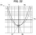
- FIG. 22 shows another example of the reference figure setting screen 252 according to the fifth example.
- a reference line 69a representing a graph of a quadratic function and a reference rectangle 69b with the minimum point of the reference line 69a as its center are drawn.
- the reference rectangle 69b represents a boundary defining a determination region R7.
- the reference line 69a and the reference rectangle 69b are examples of reference figures.
- an answer figure 79a of a curve for the reference line 69a is drawn.
- the scoring variables (i) to (iii) below can be set, and a score can be calculated by the scoring logic of combination of these scoring variables.
- the scoring logic can be set to add a score of "1" if the value in (i) is 0.75 or larger, add a score of "1" if (ii) satisfies a predetermined analogy condition, and add a score of "1" if the minimum point satisfies the positional relationship in (iii).
- the maximum point can be used as a feature point. If the reference line 69a represents a graph of a quadratic function being convex upward, the maximum point can be used as a feature point. If the reference line 69a represents a graph of a cubic function, the maximum point, the minimum point or the inflection point may be used as a feature point.
- the scoring server 10 as the information processing apparatus according to the embodiment includes the CPU 11 (processor) that executes the scoring criterion generation program 131 (program) stored in the storage 13.
- the CPU 11 generates the scoring criterion data 332 (scoring criterion information) that is referenced in the scoring process of an answer figure to a problem that requires drawing of a figure in a Cartesian coordinate system that is the coordinate plane 51, wherein in response to a reference figure(s) (reference line 61, reference rectangles 62, etc.) being drawn on the coordinate plane 51 based on a user operation(s), the coordinate plane 51 being displayed on the display 25 of the client terminal 20, the scoring criterion data 332 including information on a scoring criterion(s) determined based on the reference figure is generated.
- a reference figure(s) reference line 61, reference rectangles 62, etc.
- the reference rectangles 62 as reference figures represent boundaries respectively defining the determination regions R0, R1, and the scoring criterion data 332 is used in the scoring process to determine whether the answer figure 71 is partly in each of the determination regions R0, R1.
- the reference lines 63, 64 as reference figures represent boundaries respectively defining the determination regions R2, R3, and the scoring criterion data 332 is used in the scoring process to determine whether the answer figure 71 is fully in each of the determination regions R2, R3.
- Each of these makes it possible to easily set the correct answer range, which is used as a scoring criterion(s), in a visual and intuitive manner.
- the reference rectangles 62 as reference figures represent boundaries respectively defining the determination regions R0, R1
- the scoring criterion data 332 is used in the scoring process to determine whether the endpoints P0, P1 as feature points of the answer figure 71 are respectively located in the determination regions R0, R1. This makes it possible to easily set the correct answer range, which is used as a scoring criterion (s), in a visual and intuitive manner.
- the answer figures 77a, 77b, 78a, 78b, 79a are each a straight line or a curve of a graph, and a feature point(s) of each answer figure is/are the endpoint(s) of the straight line or the endpoint(s), maximum point, minimum point or inflection point of the curve. This makes it possible to easily and properly set scoring criteria for a problem that requires drawing of a straight line(s) or a curve(s).
- the reference rectangles 62, 65, 66 as reference figures are each a rectangle having sides parallel to the coordinate axes of the coordinate plane 51. This makes it possible for the CPU 11 to identify the positional relationship between a reference figure(s) and an answer figure by a simple process.
- the CPU 11 identifies a position(s) of the reference rectangle(s) 62, 65, 66 on the coordinate plane 51 based on the user operation to specify positions of opposite vertices of the reference rectangle(s) 62, 65, 66 on the coordinate plane 51. This makes it possible to display reference figures by simple operations.
- two reference lines 63, 64 as reference figures represent a boundary defining the determination region R4, and the scoring criterion information 332 is used in the scoring process to determine whether the answer figure 71 is fully in the determination region R4. This makes it possible to easily and flexibly set a determination region by adjusting the slope or intercept of each reference line.
- the CPU 11 sets the determination regions R2, R3 based on the user operation to specify one side or the other side of the respective reference lines 63, 64 on the coordinate plane 51, and the user operation to specify the one side or the other side of the respective reference lines 63, 64 is an operation to put a predetermined cursor, 55, on the one side or the other side of the respective reference lines 63, 64 on, of the display 25, the display screen where the reference lines 63, 64 are displayed. This makes it possible to specify determination regions by simple operations.
- the scoring criterion data 332 is used in the scoring process to make a determination as to an analogy in shape between the answer figure(s) and it/their reference figure (s) . This makes it possible to easily set scoring criteria about the analogy in shape in a visual and intuitive manner.
- the reference rectangle 66 as a reference figure is a figure that encloses a predetermined region on the coordinate plane 51, and the scoring criterion data 332 is used in the scoring process to make a determination as to a comparison in area between the answer figure 76 and the reference rectangle 66. This makes it possible to easily set scoring criteria about the comparison in area in a visual and intuitive manner.
- the scoring criterion data 332 is used in the scoring process to make a determination, for example, as to distance (s) between each endpoint of the respective answer figures 77a, 77b as a feature point and their reference lines 67a, 67b as reference figures shown in FIG. 20 .
- This makes it possible to easily set scoring criteria about the distance from a reference figure (i.e., position of an answer figure) in a visual and intuitive manner.
- the CPU 11 performs the scoring process based on the individual data for scoring 334 that includes the scoring criterion data 332 and the answer data 333 on the answer figure. This makes it possible to perform automatic scoring based on set scoring criteria.
- the storage 13 stores the scoring criterion generation program 131 that causes the CPU 11 of the scoring server 10 to generate the scoring criterion data 332 that is referenced in the scoring process of an answer figure to a problem that requires drawing of a figure in a Cartesian coordinate system that is the coordinate plane 51, wherein in response to a reference figure(s) (reference line 61, reference rectangles 62, etc.) being drawn on the coordinate plane 51 based on a user operation(s), the coordinate plane 51 being displayed on the display 25 of the client terminal 20, the scoring criterion data 332 including information on a scoring criterion(s) determined based on the reference figure is generated.
- This makes it possible to easily set scoring criteria in a visual and intuitive manner.
- the information processing method is performed by, as a computer, the CPU 11 of the scoring server 10, and includes generating the scoring criterion data 332 that is referenced in the scoring process of an answer figure to a problem that requires drawing of a figure in a Cartesian coordinate system that is the coordinate plane 51, wherein in response to a reference figure(s) (reference line 61, reference rectangles 62, etc.) being drawn on the coordinate plane 51 based on a user operation(s), the coordinate plane 51 being displayed on the display 25 of the client terminal 20, the scoring criterion data 332 including information on a scoring criterion(s) determined based on the reference figure is generated.
- a reference figure(s) reference line 61, reference rectangles 62, etc.
- the scoring system 1 includes the scoring server 10, the client terminal 20 and the client server 30, but is not limited thereto.
- the scoring system 1 may have an information processing apparatus provided with the functions of the scoring server 10, the client terminal 20 and the client server 30.
- the functions of the scoring server 10, the client terminal 20 and the client server 30 may be shared by two or more information processing apparatuses.
- part of the functions may be performed by cloud computing.
- a CPU first processor
- a CPU second processor
- scoring criterion generation program 131 scoring program 132
- automatic scoring script 331 scoring criterion data 332, answer data 333, individual data for scoring 334 and scoring result data 335
- answer data 333 individual data for scoring 334 and scoring result data 335
- scoring logic relevant to scoring criteria is not limited to those exemplified above as far as it somehow references the positions and/or shapes of reference figures.
- the scoring process is performed with the individual data for scoring 334 obtained by inserting the answer data 333 into the scoring criterion data 332, but not limited thereto.
- the scoring process can be performed in any manner as far as the scoring criterion information on a scoring criterion(s) and the answer information on an answer are referenced therein.
- figures are drawn in an xy Cartesian coordinate system that is a coordinate plane, but not limited thereto.
- the present disclosure is also applicable to a case where figures are drawn in an xyz Cartesian coordinate system that is a coordinate space.
- reference figures, answer figures and correct figures may be solids in the coordinate space.
- the HDD or SDD of the storage 13 is used as the non-transitory computer-readable storage medium of the present disclosure, it is not limited thereto.
- the non-transitory computer-readable storage medium may be an information storage medium, such as a flash memory or a CD-ROM.
- a carrier wave can be used as a medium to provide data of the programs of the present disclosure via a communication line.
Landscapes
- Engineering & Computer Science (AREA)
- Theoretical Computer Science (AREA)
- General Physics & Mathematics (AREA)
- Physics & Mathematics (AREA)
- General Engineering & Computer Science (AREA)
- Business, Economics & Management (AREA)
- Human Computer Interaction (AREA)
- Educational Administration (AREA)
- Educational Technology (AREA)
- Marketing (AREA)
- Quality & Reliability (AREA)
- Strategic Management (AREA)
- Tourism & Hospitality (AREA)
- General Business, Economics & Management (AREA)
- Operations Research (AREA)
- Human Resources & Organizations (AREA)
- Entrepreneurship & Innovation (AREA)
- Economics (AREA)
- Electrically Operated Instructional Devices (AREA)
Abstract
Description
- The present disclosure relates to an information processing apparatus, a storage medium and an information processing method.
- As disclosed in
JP 2006-251203 A - Regarding problems that require drawing of figures, such as graphs, on coordinate planes, a restriction has been imposed on the degree of freedom of drawing in answering, thereby realizing automatic scoring with simple scoring criteria. For example, in an answering method of selecting two points on a coordinate plane, thereby automatically drawing a straight line that connects the two points, a snap technique that limits selectable points to integer coordinates is used. This enables automatic scoring with a simple scoring criterion according to which an answer is connect if coordinates of the answer and coordinates of a correct answer (model answer) exactly match.
- However, the imposition of the restriction on the degree of freedom in answering cannot always measure examinees' understandings of problems effectively.
- Meanwhile, in order to increase the degree of freedom in answering, a scoring criterion(s) representing a correct answer range, in which answers are determined to be correct, needs to be set in advance so that answer figures approximate to a model answer are determined to be correct. If, in setting such a scoring criterion(s), a conventional method of specifying a range on a coordinate plane by a user specifying numerical values is used, an error is likely to occur, and also it is troublesome.
- According to an aspect of the present disclosure, there is provided an information processing apparatus including:
- a processor that executes a program stored in a storage, and generates scoring criterion information that is referenced in a scoring process of an answer figure to a problem that requires drawing of a figure in a Cartesian coordinate system that is a coordinate plane or a coordinate space,
- wherein in response to a reference figure being drawn in the Cartesian coordinate system based on a user operation, the Cartesian coordinate system being displayed on a display, the scoring criterion information including information on a scoring criterion determined based on the reference figure is generated..
- According to another aspect of the present disclosure, there is provided a non-transitory computer-readable storage medium storing a program that causes a processor of an information processing apparatus to generate scoring criterion information that is referenced in a scoring process of an answer figure to a problem that requires drawing of a figure in a Cartesian coordinate system that is a coordinate plane or a coordinate space,
wherein in response to a reference figure being drawn in the Cartesian coordinate system based on a user operation, the Cartesian coordinate system being displayed on a display, the scoring criterion information including information on a scoring criterion determined based on the reference figure is generated. - According to another aspect of the present disclosure, there is provided an information processing method that is performed by a computer, including:
- generating scoring criterion information that is referenced in a scoring process of an answer figure to a problem that requires drawing of a figure in a Cartesian coordinate system that is a coordinate plane or a coordinate space,
- wherein in response to a reference figure being drawn in the Cartesian coordinate system based on a user operation, the Cartesian coordinate system being displayed on a display, the scoring criterion information including information on a scoring criterion determined based on the reference figure is generated.
- The accompanying drawings, which are incorporated in and constitute a part of the specification, illustrate embodiments, and together with the general description given above and the detailed description of the embodiments given below, serve to explain the principles of the present disclosure, wherein:
-
FIG. 1 shows a schematic configuration diagram of a scoring system; -
FIG. 2 is a block diagram showing a functional configuration of a scoring server; -
FIG. 3 is a block diagram showing a functional configuration of a client terminal; -
FIG. 4 is a block diagram showing a functional configuration of a client server; -
FIG. 5 is a sequence diagram to explain a scoring criterion generation process; -
FIG. 6 shows an example of a scoring criterion setting screen; -
FIG. 7 shows examples of contents of scoring criterion data; -
FIG. 8 is a sequence diagram to explain a scoring process; -
FIG. 9 shows a reference figure setting screen according to a first example; -
FIG. 10 shows an example of the scoring criterion setting screen reflecting the contents of the reference figure setting screen shown inFIG. 9 ; -
FIG. 11 shows another example of the scoring criterion setting screen reflecting the contents of the reference figure setting screen shown inFIG. 9 ; -
FIG. 12 shows the reference figure setting screen according to a second example; -
FIG. 13 is an illustration to explain a determination region setting method; -
FIG. 14 is an illustration to explain the determination region setting method; -
FIG. 15 shows an example of the scoring criterion setting screen reflecting the contents of the reference figure setting screen shown inFIG. 14 ; -
FIG. 16 shows the reference figure setting screen according to a third example; -
FIG. 17 shows an example of the scoring criterion setting screen reflecting the contents of the reference figure setting screen shown inFIG. 16 ; -
FIG. 18 shows the reference figure setting screen according to a fourth example; -
FIG. 19 shows an example of the scoring criterion setting screen reflecting the contents of the reference figure setting screen shown inFIG. 18 ; -
FIG. 20 shows an example of the reference figure setting screen according to a fifth example; -
FIG. 21 shows another example of the reference figure setting screen according to the fifth example; and -
FIG. 22 shows another example of the reference figure setting screen according to the fifth example. - Hereinafter, one or more embodiments of the present disclosure will be described with reference to the drawings.
-
FIG. 1 is a schematic configuration diagram of ascoring system 1 according to an embodiment(s). - The
scoring system 1 includes a scoring server 10 (information processing apparatus), aclient terminal 20 and aclient server 30. Thescoring server 10, theclient terminal 20 and theclient server 30 are connected to one another via a communication network N to perform information communications. The communication network N is, for example, the Internet, but not limited thereto and may be another network, such as a LAN (Local Area Network). - The
scoring system 1 is a computer system that provides automatic scoring services in CBT. Thescoring system 1 of this embodiment can perform automatic scoring of answers to problems (questions) that each require drawing of a figure(s) in a Cartesian coordinate system that is a coordinate plane. Thescoring system 1 may also be able to perform automatic scoring of answers to problems in other formats (e.g., problem that requires selection of a correct answer from multiple choices, problem that requires input of a numerical value as an answer, etc.). In response to a request from theclient terminal 20, thescoring server 10 of thescoring system 1 generates scoring criterion data 332 (scoring criterion information) (shown inFIG. 4 ) including information on a scoring criterion (s) for a problem and sends it to the client server 30 (scoring criterion generation process). Further, in response to a call for an automatic scoring API from theclient server 30, thescoring server 10 determines a score of an answer figure to a problem and sendsscoring result data 335 including information on a scoring result to the client server 30 (scoring process). In the scoring process, thescoring server 10 references the scoring criterion included in thescoring criterion data 332. Details of these processes will be described later. -
FIG. 2 is a block diagram showing a functional configuration of thescoring server 10. Thescoring server 10 includes a CPU (Central Processing Unit) 11, a RAM (Random Access Memory) 12, astorage 13, anoperation unit 14, adisplay 15, acommunication unit 16 and abus 17. The components of thescoring server 10 are connected to one another via thebus 17. - The
CPU 11 is a processor that controls operation of the components of thescoring server 10. TheCPU 11 reads a scoringcriterion generation program 131, ascoring program 132 or the like among various programs stored in thestorage 13, loads the read program to a work area of theRAM 12, and performs a process among various processes in accordance with the loaded program. For example, theCPU 11 executes the scoringcriterion generation program 131 to provide theclient terminal 20 with a UI (User Interface) for generating scoring criteria, and also generate scoringcriterion data 332 based on user operations at theclient terminal 20 and send it to theclient server 30. Further, when the automatic scoring API is called in response to a call from theclient server 30, theCPU 11 executes thescoring program 132 to determine a score of an answer, generate scoringresult data 335 and send it to theclient server 30. The scoringserver 10 may have two or more processors (e.g., two or more CPUs), and these processors may perform processes that theCPU 11 of this embodiment performs. In this case, the processors may be involved in each process, or may independently perform different processes in parallel. - The
RAM 12 provides theCPU 11 with a memory space for working, and stores temporary data. TheRAM 12 may include a nonvolatile memory. - The
storage 13 is a non-transitory computer-readable storage medium that stores programs, data and so forth readable by theCPU 11 as a computer, and is configured by an HDD (Hard Disk Drive), an SSD (Solid State Drive) or the like. Thestorage 13 stores programs that are executed by theCPU 11, such as the scoringcriterion generation program 131 and thescoring program 132, data that is referenced in execution of the programs, and so forth. The programs are stored in thestorage 13 in the form of computer-readable program codes. - The
operation unit 14 includes a pointing device, such as a mouse, and a keyboard, and receives user's point inputs, key inputs and so forth, and outputs information on these operations to theCPU 11. - The
display 15 includes a display device, such as a liquid crystal display, and displays various kinds of information on the display device in accordance with display control signals from theCPU 11. - The
communication unit 16 includes a router and a network card. Via thecommunication unit 16, theCPU 11 sends and receives data to and from theclient terminal 20 and theclient server 30 on the communication network N by communication connection therewith. -
FIG. 3 is a block diagram showing a functional configuration of theclient terminal 20. - The
client terminal 20 is a computer device that is used by a user who uses services of the scoring system 1 (e.g., teacher who manages student answers and scoring results thereof). Theclient terminal 20 is, for example, a laptop PC (Personal Computer), a desktop PC, a tablet terminal, a smartphone or the like. Theclient terminal 20 requests, on abrowser 231, the scoringserver 10 and theclient server 30 to perform various processes in accordance with input operations made by the user, and displays, on adisplay 25, process results sent from the scoringserver 10 and so forth. - The
client terminal 20 includes aCPU 21, aRAM 22, a storage 23, anoperation unit 24, adisplay 25, acommunication unit 26 and abus 27. The components of theclient terminal 20 are connected to one another via thebus 27. - The
CPU 21 is a processor that controls operation of the components of theclient terminal 20. TheCPU 21 reads a program, such as thebrowser 231, among various programs stored in the storage 23, loads the read program to a work area of theRAM 22, and performs a process among various processes in accordance with the loaded program. - The
RAM 22 provides theCPU 21 with a memory space for working, and stores temporary data. TheRAM 22 may include a nonvolatile memory. - The storage 23 is a non-transitory computer-readable storage medium that stores programs, data and so forth readable by the
CPU 21 as a computer, and is configured by an HDD, an SSD or the like. The storage 23 stores programs that are executed by theCPU 21, such as thebrowser 231, data that is referenced in execution of the programs, and so forth. The programs are stored in the storage 23 in the form of computer-readable program codes. Thebrowser 231 is a program to display, on thedisplay 25, execution results of various programs sent from the scoringserver 10 and theclient server 30, information on web pages on the Internet, and so forth. - The
operation unit 24, thedisplay 25 and thecommunication unit 26 are respectively the same as theoperation unit 14, thedisplay 15 and thecommunication unit 16 of the scoringserver 10 in configuration, and hence their descriptions will be omitted. -
FIG. 4 is a block diagram showing a functional configuration of theclient server 30. - The
client server 30 is a computer device that stores data (e.g., scoring criterion data for each problem, answer data, scoring result data, etc.) managed by the user who uses services of thescoring system 1, and also stores and executes an automatic scoring script(s) generated by the user. - The
client server 30 includes aCPU 31, aRAM 32, astorage 33, anoperation unit 34, adisplay 35, acommunication unit 36 and abus 37. The components of theclient server 30 are connected to one another via thebus 37. - The
CPU 31 is a processor that controls operation of the components of theclient server 30. TheCPU 31 reads a program, such as anautomatic scoring script 331, among various programs stored in thestorage 33, loads the read program to a work area of theRAM 32, and performs a process among various processes in accordance with the loaded program. For example, theCPU 31 executes theautomatic scoring script 331 to call the automatic scoring API of the scoringserver 10 with individual data for scoring 334 as arguments, thereby causing the scoringserver 10 to generate scoringresult data 335, and obtains the scoringresult data 335. In this specification, programs include scripts that are executable without being compiled. - The
RAM 32 provides theCPU 31 with a memory space for working, and stores temporary data. TheRAM 32 may include a nonvolatile memory. - The
storage 33 is a non-transitory computer-readable storage medium that stores programs, data and so forth readable by theCPU 31 as a computer, and is configured by an HDD, an SSD or the like. Thestorage 33 stores programs that are executed by theCPU 31, such as theautomatic scoring script 331, data that is referenced in execution of the programs, and so forth. The programs are stored in thestorage 33 in the form of computer-readable program codes. Theautomatic scoring script 331 is usually created by the user of thescoring system 1 for a purpose, but a pre-created one may be used. - Examples of the data stored in the
storage 33 include scoringcriterion data 332, answer data 333 (answer information), individual data for scoring 334 and scoringresult data 335. - The scoring
criterion data 332 is referenced in the scoring process of an answer figure to a problem that requires drawing of a figure in a Cartesian coordinate system that is a coordinate plane. The scoringcriterion data 332 includes information on a scoring criterion(s) that is used in the scoring process. The scoringcriterion data 332 is generated by the scoringserver 10 in response to a request from theclient terminal 20, and sent to theclient server 30 and stored in thestorage 33. The scoringcriterion data 332 is a file in a format referenceable as arguments in execution of the automatic scoring API of the scoringserver 10, a file in json format in this embodiment. - The
answer data 333 is data of an answer figure generated by an answerer who tackles a problem, such as a student, with a not-shown terminal device for answering. If there are two or more answerers, theanswer data 333 is generated by/for each answerer. Data items included in theanswer data 333 are predetermined for each problem. - The individual data for scoring 334 is data made of the
answer data 333 of an answerer (individual) inserted into the scoringcriterion data 332. Hence, the individual data for scoring 334 includes the scoring criterion information and the answer information generated by one answerer. If there are two or more answerers, the individual data for scoring 334 is generated for each answerer. The individual data for scoring 334 is a file in the same format as the scoringcriterion data 332, the json format in this embodiment. - The scoring
result data 335 includes information on a scoring result of an answer. The scoringresult data 335 is generated by the scoringserver 10 with the automatic scoring API called with the individual data for scoring 334 as arguments, and sent to theclient server 30. - The
operation unit 34, thedisplay 35 and thecommunication unit 36 are respectively the same as theoperation unit 14, thedisplay 15 and thecommunication unit 16 of the scoringserver 10 in configuration, and hence their descriptions will be omitted. - Next, operation of the
scoring system 1 will be described, focusing on operation to generate a scoring criterion(s) and operation to determine a score of an answer using the scoring criterion. Although the main agents of these operations are theCPU 11 of the scoringserver 10, theCPU 21 of theclient terminal 20 and theCPU 31 of theclient server 30, hereinafter the scoringserver 10, theclient terminal 20 and theclient server 30 may be referred to as the main agents for the sake of convenience. -
FIG. 5 is a sequence diagram to explain the scoring criterion generation process. -
FIG. 5 shows flow of signals that are sent and received between the scoringserver 10, theclient terminal 20 and theclient server 30 in the scoring criterion generation process. - First, a user who uses a function of automatic scoring provided by the
scoring system 1 starts thebrowser 231 at theclient terminal 20, and accesses a predetermined URL. Theclient terminal 20 then requests the scoringserver 10 to send display data for displaying a scoring criterion setting screen 251 (Step S101). In response to the request, the scoringserver 10 executes the scoringcriterion generation program 131, and sends the display data for displaying the scoringcriterion setting screen 251 to theclient terminal 20 to cause theclient terminal 20 to display the scoringcriterion setting screen 251 on the display 25 (Step S102). -
FIG. 6 shows an example of the scoringcriterion setting screen 251. - On the scoring
criterion setting screen 251, reference/correct answer information 41,reference geometry information 42,answer figure information 43, scoringvariable information 44, scoringlogic information 45, aquestion ID 461, asubsidiary question ID 462, asave button 47, a referencefigure drawing button 48 and so forth are displayed. Hereinafter, a point having "a" as x-coordinate and "b" as y-coordinate on an x-y coordinate plane that is used for answering a problem is referred to as a point (a, b). - The reference/
correct answer information 41 is information on a correct figure set by the user as a model answer to a problem. InFIG. 6 , a straight line L0 having Point 0 (5, 10) and Point 1 (-5, -10) as two endpoints is set as a correct figure. The setting "Bind by index" means that scoring is carried out by taking the answering order of multiple answer elements provided after this setting into account. In the example shown inFIG. 6 , a point selected first in answering by an answerer is treated asPoint 0, and a point selected second in answering by the answerer is treated asPoint 1. If the part "index" in the "Bind by index" is changed from a drop-down list to be "Bind by any", scoring is carried out without taking the answering order into account. In this case, the two points selected first and second are treated as "Point 0,Point 1" and "Point 1,Point 0", and both combinations are subjected to scoring. The one having a higher score is adopted as a scoring result. - The
reference geometry information 42 is information on geometries that are referenced in the scoring process. InFIG. 6 , as a reference geometry, "graphBounds" representing a coordinate plane that is used for answering is set. The "graphBounds" in this embodiment is a rectangular region (square region, to be more specific) having a length in x-direction of 20 and a length in y-direction of 20 with a point (-10, -10) as the lower left end. InFIG. 6 , only one reference geometry, the "graphBounds", is set, but two or more reference geometries may be set. - The
answer figure information 43 is data on an answerer's answer figure. At the stage where scoring criteria are set, dummyanswer figure information 43 is input for providing parts into which an answerer's answer data is to be inserted. In this embodiment, coordinate data of the two endpoints P0 (Point 0), P1 (Point 1) of the straight line L0 as an answer figure is input to correspond to the reference/correct answer information 41. - The scoring
variable information 44 is information on scoring variables to construct scoring logic in thescoring logic information 45. In this embodiment, to the scoring variable "correct", a value of the automatic scoring function "equalsAll" is assigned. The automatic scoring function "equalsAll" is a function to return "true (1)" if data of the reference/correct answer information 41 (in this embodiment, coordinates ofPoint 0 and Point 1) and data of the answer figure information 43 (same as the above, i.e., coordinates ofPoint 0 and Point 1) exactly match, and returns "false (0)" if they do not exactly match. InFIG. 6 , one scoring variable is used, but two or more scoring variables may be set. - The scoring
logic information 45 is information on the scoring logic using the scoring variable(s) in the scoringvariable information 44. InFIG. 6 , the logical formula "score = correct" determines a score. In the example shown inFIG. 6 , the data of the reference/correct answer information 41 and the data of theanswer figure information 43 do not exactly match, so that the scoring variable "correct" is "false (0)", and the score is "0". - The
question ID 461 is a unique code assigned to a question (problem). Thequestion ID 461 can call the scoringcriterion data 332 for the problem. Thesubsidiary question ID 462 is a unique code assigned to a subsidiary question (subsidiary problem) included in a problem. If a problem includes two or more subsidiary problems, the scoringcriterion data 332 for the problem includes information on two or more sets of scoring criteria for the respective subsidiary problems. In this case, scoring can be carried out, for example, by a method of adding up scores of subsidiary problems of a problem to be the total score of the problem or a method of determining that a problem is correctly answered if all subsidiary problems of the problem are correctly answered. - The
save button 47 is a button for generating scoringcriterion data 332 with the contents of the scoringcriterion setting screen 251 at the time. - The reference
figure drawing button 48 is a button that is selected to draw, on a graph viewer, reference figures that are used for setting scoring criteria. A method for setting scoring criteria using reference figures will be described later. - When the
save button 47 is selected, theclient terminal 20 sends a request to the scoringserver 10 to generate scoring criterion data 332 (Step S103 inFIG. 5 ). The scoringserver 10 that has received the request performs a process in accordance with the scoringcriterion generation program 131, generates scoringcriterion data 332 in the json format and sends it to the client server 30 (Step S104). When the scoringcriterion data 332 is stored in thestorage 33 of theclient server 30 in Step S104, the scoring criterion generation process ends. -
FIG. 7 shows examples of contents of scoringcriterion data 332. - As an example,
FIG. 7 shows the scoringcriterion data 332 reflecting the contents of the scoringcriterion setting screen 251 shown inFIG. 6 . The scoringcriterion data 332 includes a subsidiary question ID, scoring logic, a correct answer (contents of the reference/correct answer information 41), an answerer's answer (contents of the answer figure information 43) and an answerer ID to identify an answerer. The scoringcriterion data 332 shown inFIG. 7 is merely an example and hence is not limited to the format shown therein. - Next, the scoring process for automatically determining a score of an answer figure using generated scoring
criterion data 332 will be described. -
FIG. 8 is a sequence diagram to explain the scoring process. - The scoring process is started by a predetermined user operation at the
client terminal 20 in a state in which scoringcriterion data 332 and answerdata 333 are stored in thestorage 33 of theclient server 30. - When the scoring process is started, the
client terminal 20 requests theclient server 30 to start the automatic scoring script 331 (Step S201). - In response to the request, the
client server 30 executes theautomatic scoring script 331. Theclient server 30 first inserts oneanswer data 333 into the scoringcriterion data 332 to generate individual data for scoring 334, and stores it in the storage 33 (Step S202). In Step S202, theclient server 30 generates the individual data for scoring 334 by replacing the "Answerer's Answer" in the scoringcriterion data 332 shown inFIG. 7 with the contents of the actual answer of an answerer. In this manner, theclient server 30 generates the individual data for scoring 334 that includes the information on the scoring criterion included in the scoringcriterion data 332 and theanswer data 333 of an answerer. - Next, the
client server 30 calls the automatic scoring API of the scoringserver 10 with the individual data for scoring 334 generated in Step S202 as arguments (Step S203). In response to the call for the automatic scoring API, the scoringserver 10 executes thescoring program 132, generates scoringresult data 335 and sends it to the client server 30 (Step S204). In this embodiment, the scoringserver 10 determines a score of theanswer data 333 included in the received individual data for scoring 334, referencing the scoring criterion of the scoringcriterion data 332 included in the individual data for scoring 334. In the case shown inFIG. 6 andFIG. 7 , the scoringserver 10 first compares the coordinates in the reference/correct answer information 41 with the coordinates in theanswer figure information 43 corresponding to theanswer data 333, and obtains a value of the scoring variable "correct". The scoringserver 10 then calculates a score in accordance with the scoring logic "score = correct", and generates scoringresult data 335 including information on the score. - When receiving the scoring
result data 335, theclient server 30 determines whether scoring has finished for all answerers (Step S205). If theclient server 30 determines that there is at least one answerer for whom scoring has not finished yet (Step S205; "NO"), theclient server 30 performs Step S202 again with theanswer data 333 of the next answerer. If theclient server 30 determines that scoring has finished for all answerers (Step S205; "YES"), theclient server 30 exits theautomatic scoring script 331. Thus, the scoring process ends. - In the
scoring system 1 of this embodiment, in order to set scoring criteria with the scoringcriterion setting screen 251, it is possible to display (draw) reference figures on thedisplay 25 of theclient terminal 20 and reflect information on the reference figures in the scoring criteria. Hereinafter, first to fifth examples of the method for setting scoring criteria with reference figures will be described. - First, as a first example, a case will be described where determination regions are defined by reference figures, and a scoring criterion about a positional relationship between the determination regions and an answer figure is set.
-
FIG. 9 shows a referencefigure setting screen 252 according to the first example. - The reference
figure setting screen 252 is the graph viewer displayed on thedisplay 25 when the referencefigure drawing button 48 is selected on the scoringcriterion setting screen 251. On the referencefigure setting screen 252, a coordinate plane 51 (Cartesian coordinate system), amode selection button 52, areference line 61,reference rectangles 62, an answer figure 71 and so forth are displayed. Among these, thereference line 61 and thereference rectangles 62 are examples of reference figures. - The coordinate
plane 51 corresponds to the "graphBounds" set in thereference geometry information 42 on the scoringcriterion setting screen 251. On this coordinateplane 51, thereference line 61, thereference rectangles 62 and the answer figure 71 are drawn, for example. The coordinate ranges (x-range, y-range) and grid spacing(s) (x grid spacing, y grid spacing) of the coordinateplane 51 can be changed by inputting numerical values intext boxes 53 provided at the right side on the referencefigure setting screen 252. This change is reflected in the contents of the "graphBounds" in thereference geometry information 42 on the scoringcriterion setting screen 251. Further, reference values can be displayed on the x axis and/or the y axis of the coordinateplane 51 in accordance with to user operations. For example, "0" representing the origin can be displayed at the intersection of the x axis and the y axis. - The
mode selection button 52 is a button for specifying a mode for drawing reference figures on the referencefigure setting screen 252. When themode selection button 52 is selected, a not-shown group of icons representing multiple drawing mode choices is displayed, and the current drawing mode can be changed to another by selecting an icon from the icons. The drawing modes include a line drawing mode for drawing reference lines as reference figures, a region specifying mode for specifying regions based on reference lines, and a rectangle drawing mode for drawing reference rectangles as reference figures. - In this example, the
reference line 61 corresponds to the straight line L0 (correct figure set by the user as a model answer to a problem) set in the reference/correct answer information 41 on the scoringcriterion setting screen 251. Thereference line 61 can be generated by selecting the line drawing mode with themode selection button 52, and making an operation(s) to specify two endpoints on the coordinate plane 51 (e.g., operations of putting a mouse cursor on desired points and clicking). For specifying the endpoints, the snap technique may be employed that limits selectable points to integer coordinates. The shape of thereference line 61 may be changed by an operation(s) to change the position(s) of the endpoint(s) of thereference line 61, and this change may be reflected in the reference/correct answer information 41 on the scoringcriterion setting screen 251. On the contrary, if the coordinate data of one or both of the two endpoints (Point 0, Point 1) in the reference/correct answer information 41 is changed, this change may be reflected in thereference line 61 on the referencefigure setting screen 252. - The
reference rectangles 62 are rectangles having sides parallel to the coordinate axes of the coordinateplane 51. Thereference rectangles 62 shown inFIG. 9 are squares having a length of each side of 2 with the two endpoints of thereference line 61 as their respective centers. Thereference rectangles 62 represent boundaries respectively defining determination regions R0, R1. The positional relationship between these determination regions R0, R1 and the answer figure 71 can be set as a scoring criterion. For example, the scoring criterion can be set such that the answer figure 71 is determined to be correct if it is partly in each of the determination regions R0, R1. In this case, not only the answer figure 71 that exactly matches with thereference line 61 as a correct figure but also the answer figure 71 that is partly in each of the determination regions R0, R1 are determined to be correct. Alternatively, the scoring criterion may be set such that the answer figure 71 having predetermined feature points (two endpoints P0, P1) respectively located in the determination regions R0, R1 is determined to be correct. - The
reference rectangles 62 are drawn on the coordinateplane 51 in accordance with user operations in a state in which the rectangle drawing mode is selected with themode selection button 52. The user operations are, for example, operations to specify positions of opposite vertices of thereference rectangles 62 on the coordinateplane 51. On the basis of these user operations, theCPU 11 identifies the positions of thereference rectangles 62 on the coordinateplane 51. The user operations may be drag operations. In this case, theCPU 11 identifies the start point and the end point of each drag operation as the positions of opposite vertices of eachreference rectangle 62. For specifying the positions of the opposite vertices of thereference rectangles 62, the snap technique may be employed that limits selectable points to integer coordinates. - The answer figure 71 corresponds to the straight line L0 in the
answer figure information 43 on the scoringcriterion setting screen 251. At the stage where criteria are generated, the answer figure 71 is a dummy. -
FIG. 10 shows an example of the scoringcriterion setting screen 251 reflecting the contents of the referencefigure setting screen 252 shown inFIG. 9 . - In the
reference geometry information 42 on the scoringcriterion setting screen 251 shown inFIG. 10 , as reference geometries, the "graphBounds" representing a coordinate region for answering and the determination regions "R0", "R1" corresponding to the tworeference rectangles 62 are defined and displayed. The coordinate data or the like representing the determination regions "R0", "R1" in thereference geometry information 42 is calculated by theCPU 11 from the contents of the determination regions R0, R1 on the referencefigure setting screen 252 and displayed. This eliminates the need for the user to input coordinate data of the determination regions "R0", "R1" as reference geometries and accordingly saves user time and effort. - In the scoring
variable information 44, the scoring variables "satisfied_0" and "satisfied_1" are defined and displayed. To the scoring variable "satisfied_0", a value of the automatic scoring function "lineHits" with the straight line "L0" in theanswer figure information 43 and the determination region "R0", which is a reference geometry, as arguments is assigned. To the scoring variable "satisfied_1", a value of the automatic scoring function "lineHits" with the straight line "L0" in theanswer figure information 43 and the determination region "R1", which is a reference geometry, as arguments is assigned. The automatic scoring function "lineHits" is a function to return "true" if a straight line as an argument is partly in a determination region as an argument. - In the
scoring logic information 45, the scoring logic is defined to make the "score" "1" if the scoring variables "satisfied_0" and "satisfied_1" are both "true". In the case shown inFIG. 9 andFIG. 10 , the straight line L0 (answer figure 71) in theanswer figure information 43 is partly in each of the determination regions R0, R1, so that the "score" calculated is "1". Thus, the scoringcriterion data 332 generated with the scoringcriterion setting screen 251 shown inFIG. 10 is used in the scoring process to determine whether the answer figure 71 is partly in each of the determination regions R0, R1. -
FIG. 11 shows another example of the scoringcriterion setting screen 251 reflecting the contents of the referencefigure setting screen 252 shown inFIG. 9 . - In the scoring
variable information 44 on the scoringcriterion setting screen 251 shown inFIG. 11 , the scoring variables "in1", "in2" and "correct" are defined and displayed. To the scoring variable "in1", a value of the automatic scoring function "inBox" with "L0.points[0]" representing one endpoint P0 of the straight line L0 in theanswer figure information 43 and the determination region "R0" as arguments is assigned. To the scoring variable "in2", a value of the automatic scoring function "inBox" with "L0.points[1]" representing the other endpoint P1 of the straight line L0 in theanswer figure information 43 and the determination region "R1" as arguments is assigned. The automatic scoring function "inBox" is a function to return "true" if a point as an argument is located in a determination region as an argument. The scoring variable "correct" is defined to be "true" if the scoring variables "in1" and "in2" are both "true". - In the
scoring logic information 45, the logical formula "score = correct" determines a score. In the case shown inFIG. 9 andFIG. 11 , the endpoints P0, P1 of the straight line L0 (answer figure 71) in theanswer figure information 43 are respectively located in the determination regions R0, R1, so that the scoring variables "in1", "in2" and "correct" are all "true (1)", and the "score" calculated is "1". Thus, the scoringcriterion data 332 generated with the scoringcriterion setting screen 251 shown inFIG. 11 is used in the scoring process to determine whether predetermined feature points (two endpoints P0, P1 in the first example) of the answer figure 71 are respectively located in the determination regions R0, R1. - As shown in
FIG. 10 andFIG. 11 , the definitions of the scoring variables in the scoringvariable information 44 and the contents of the scoring logic in thescoring logic information 45 can be freely set by the user in accordance with a desired scoring method. - In the first example, the
reference rectangles 62 as reference figures respectively define the determination regions R0, R1. Instead of this, two or more reference lines as reference figures may define a determination region (R4), serving as its boundary. -
FIG. 12 shows the referencefigure setting screen 252 according to a second example. - On the reference
figure setting screen 252 shown inFIG. 12 , instead of thereference rectangles 62 shown inFIG. 9 ,reference lines reference line 63 corresponds to the graph of the function y =2x + 2, and thereference line 64 corresponds to the graph of the function y = 2x - 2. A region with thereference line 63 as its boundary and the y-coordinate being equal to or smaller than that of thereference line 63 is a determination region R2, and a region with thereference line 64 as its boundary and the y-coordinate being equal to larger than that of thereference line 64 is a determination region R3. In other words, the determination region R2 is a region satisfying y ≤ 2x + 2, and the determination region R3 is a region satisfying y ≥ 2x - 2. Hereinafter, the overlap area of the determination regions R2, R3 is referred to as a determination region R4. - The determination regions R2, R3 shown in
FIG. 12 are set by the following procedure. First, as shown inFIG. 13 , the region specifying mode is selected with themode selection button 52, and thereference line 63 is drawn. Thereference line 63 can be drawn by a user operation(s) to specify two points on the coordinateplane 51. From this state, a user operation (mouse over operation) is made to put acursor 55 on one side or the other side of thereference line 63 on the display screen (reference figure setting screen 252), so that the one side or the other side of thereference line 63 can be specified as the determination region R2. InFIG. 13 , thecursor 55 is put on the side having the y-coordinate smaller (x-coordinate larger) than that of thereference line 63, so that the determination region R2 is specified. The contents of the specified determination region R2 are reflected in aninformation display section 54 provided at the right side on the referencefigure setting screen 252. If the contents input in the text boxes of theinformation display section 54 are changed, this change may be reflected in thereference line 63 and the determination region R2. When a confirmation operation, such as a click operation, is made in the state shown inFIG. 13 , thereference line 63 and the determination region R2 are fixed and reflected in thereference geometry information 42 on the scoringcriterion setting screen 251. The user operation to specify the determination region R2 may be an operation other than the mouse over operation. - Next, as shown in
FIG. 14 , thereference line 64 is drawn, and thecursor 55 is put on the side having the y-coordinate larger (x-coordinate smaller) than that of thereference line 64, so that the determination region R3 is specified. When a click operation or the like is made in the state shown inFIG. 14 , thereference line 64 and the determination region R3 are fixed. Also, the determination region R4, which is the overlap area of the determination regions R2, R3, is fixed. -
FIG. 15 shows an example of the scoringcriterion setting screen 251 reflecting the contents of the referencefigure setting screen 252 shown inFIG. 14 . - In the
reference geometry information 42 on the scoringcriterion setting screen 251 shown inFIG. 15 , as reference geometries, the "graphBounds" representing a coordinate region for answering and the determination regions "R2", "R3" shown inFIG. 12 to FIG. 14 are defined and displayed. The inequalities representing the determination regions "R2", "R3" in thereference geometry information 42 are respectively calculated by theCPU 11 from the contents of thereference lines figure setting screen 252 and displayed. This eliminates the need for the user to input data for theCPU 11 to identify the determination regions R2, R3 as reference geometries and accordingly saves user time and effort. - In the scoring
variable information 44, the scoring variables "sati_pt0R2", "sati_pt0R3", "sati_pt1R2" and "sati_pt1R3" are defined and displayed. To the scoring variable "sati_pt0R2", a value of the automatic scoring function "satisfies" with "L0.pt0" representing one endpoint P0 of the straight line L0 in theanswer figure information 43 and the determination region "R2" as arguments is assigned. To the scoring variable "sati_pt0R3", a value of the automatic scoring function "satisfies" with "L0.pt0" representing one endpoint P0 of the straight line L0 in theanswer figure information 43 and the determination region "R3" as arguments is assigned. To the scoring variable "sati_pt1R2", a value of the automatic scoring function "satisfies" with "L0.pt1" representing the other endpoint P1 of the straight line L0 in theanswer figure information 43 and the determination region "R2" as arguments is assigned. To the scoring variable "sati_pt1R3", a value of the automatic scoring function "satisfies" with "L0.pt1" representing the other endpoint P1 of the straight line L0 in theanswer figure information 43 and the determination region "R3" as arguments is assigned. The automatic scoring function "satisfies" is a function to return "true" if a point as an argument is located in a determination region as an argument. - In the
scoring logic information 45, the scoring logic is defined to make the "score" "1" if the scoring variables "sati_pt0R2", "sati_pt0R3", "sati_pt1R2" and "sati_pt1R3" are all "true". The scoring variables "sati_pt0R2" and "sati_pt1R2" are both "true" if the straight line L0 (answer figure 71) in theanswer figure information 43 is (fully) located in the determination region R2, and the scoring variables "sati_pt0R3" and "sati_pt1R3" are both "true" if the straight line L0 (answer figure 71) in theanswer figure information 43 is (fully) located in the determination region R3. That is, the scoring logic shown inFIG. 15 makes the "score" "1" if the straight line L0 in theanswer figure information 43 is (fully) located in the determination region R4, which is the overlap area of the determination regions R2, R3. Thus, the scoringcriterion data 332 generated with the scoringcriterion setting screen 251 shown inFIG. 15 is used in the scoring process to determine whether the two endpoints P0, P1 of the answer figure 71 are located in the determination region R4, the boundary of which is defined by the tworeference lines - Next, as a third example, a case will be described where a scoring criterion about an analogy in shape between a reference figure and an answer figure is set.
-
FIG. 16 shows the referencefigure setting screen 252 according to the third example. InFIG. 16 , elements other than the coordinateplane 51 are not shown. The same applies toFIG. 18 ,FIG. 20 ,FIG. 21 andFIG. 22 . - In
FIG. 16 , as a reference figure, areference rectangle 65 having a length of each side of 6 with the origin as its center is drawn. Thereference rectangle 65 represents a boundary defining a determination region R5. Also, a rectangular answer figure 75 with four points on the coordinateplane 51 connected is drawn. The answer figure 75 represents a boundary defining an answer region U0. -
FIG. 17 shows an example of the scoringcriterion setting screen 251 reflecting the contents of the referencefigure setting screen 252 shown inFIG. 16 . - In the
reference geometry information 42 on the scoringcriterion setting screen 251 shown inFIG. 17 , as reference geometries, the "graphBounds" representing a coordinate region for answering and the determination region "R5" shown inFIG. 16 are defined and displayed. - In the
answer figure information 43, the answer region "U0", the boundary of which is represented by the answer figure 75, is defined. - In the scoring
variable information 44, the scoring variable "same" is defined. To the scoring variable "same", a value of the automatic scoring function "sameRegion" with the answer region "U0" in theanswer figure information 43 and the determination region "R5" as arguments is assigned. The automatic scoring function "sameRegion" is a function to return "true" if two regions as arguments exactly match. - On the scoring
criterion setting screen 251 shown inFIG. 17 , adefault precision 49 is set. Thedefault precision 49 defines an acceptable deviation amount from a correct answer (model answer). InFIG. 17 , thedefault precision 49 is set to "0". Hence, the value of the automatic scoring function "sameRegion" is "true" if four points of the answer figure 75 shown inFIG. 17 and their corresponding vertices of thereference rectangle 65 exactly match. Meanwhile, for example, if thedefault precision 49 is set to "1", the value of the automatic scoring function "sameRegion" is "true" if the four points of the answer figure 75 deviate from their corresponding vertices of thereference rectangle 65 by 1 or less. The setting of thedefault precision 49 may be included in the scoringcriterion setting screen 251 shown in any ofFIG. 6 ,FIG. 10 ,FIG. 11 andFIG. 15 too. - In the
scoring logic information 45, the logical formula "score = correct" determines a score. In the case shown inFIG. 16 and FIG. 17 , the determination region R5 does not match with the answer region U0 corresponding to the answer figure 75, so that the scoring variable "same" is "false (0)", and the "score" is "0". Thus, the scoringcriterion data 332 generated with the scoringcriterion setting screen 251 shown inFIG. 17 is used in the scoring process to make a determination as to the analogy in shape between the answer figure 75 and thereference rectangle 65 as a reference figure. - Next, as a fourth example, a case will be described where a scoring criterion about a comparison in area (square measure) between a reference figure and an answer figure is set.
-
FIG. 18 shows the referencefigure setting screen 252 according to the fourth example. - In
FIG. 18 , as a reference figure, areference rectangle 66 having a length of each side of 6 with the origin as its center is drawn. Thereference rectangle 66 represents a boundary defining a determination region R6. Also, a hexagonal answer figure 76 with six points on the coordinateplane 51 connected is drawn. The answer figure 76 represents a boundary defining an answer region U1. -
FIG. 19 shows an example of the scoringcriterion setting screen 251 reflecting the contents of the referencefigure setting screen 252 shown inFIG. 18 . - In the
reference geometry information 42 on the scoringcriterion setting screen 251 shown inFIG. 19 , as reference geometries, the "graphBounds" representing a coordinate region for answering and the determination region "R6" shown inFIG. 18 are defined and displayed. - In the
answer figure information 43, the answer region "U1", the boundary of which is represented by the answer figure 76, is defined. - In the scoring
variable information 44, the scoring variable "intersection" is defined. To the scoring variable "intersection", a value of the automatic scoring function "overlap" with the determination region "R6" and the answer region "U1" in theanswer figure information 43 as arguments is assigned. The automatic scoring function "overlap" is a function to return the value of "(area of overlap of two regions as arguments) / (area of predetermined one of the two regions as arguments)". - In the
scoring logic information 45, the logical formula "score = intersection > 0.75" determines a score. This makes the "score" "1" if the value of the scoring variable "intersection" is larger than 0.75. Thus, the scoringcriterion data 332 generated with the scoringcriterion setting screen 251 shown inFIG. 19 is used in the scoring process to make a determination as to the comparison in area between the answer figure 76 and thereference rectangle 66 as a reference figure. - Next, as a fifth example, a case will be described where scoring criteria about an analogy in shape, distance and/or the like between a reference figure(s) representing a graph(s) of a predetermined function(s) and an answer figure(s) are set.
-
FIG. 20 shows an example of the referencefigure setting screen 252 according to the fifth example. - On the reference
figure setting screen 252 shown inFIG. 20 ,reference lines reference lines reference lines - (i) Distance (minimum distance) between each endpoint of answer figure 77a and
reference line 67a - (ii) Distance (minimum distance) between each endpoint of answer figure 77b and
reference line 67b - (iii) Difference or distance between
intersection 77c of answer figures 77a, 77b andintersection 67c ofreference lines - For example, the scoring logic can be set to add a score of "1" if the distance in (i) is 1 or less, add a score of "1" if the distance in (ii) is 1 or less, and add a score of "1" if the
intersections -
FIG. 21 shows another example of the referencefigure setting screen 252 according to the fifth example. - On the reference
figure setting screen 252 shown inFIG. 21 , tworeference lines reference lines reference lines - (i) Value of "(area of overlap of smallest rectangles respectively enclosing answer figure 78a and
reference line 68a) / (area of predetermined one of the two rectangles)" - (ii) Value of "(area of overlap of smallest rectangles respectively enclosing answer figure 78b and
reference line 68b) / (area of predetermined one of the two rectangles)" - (iii) Analogy in shape between answer figures 78a, 78b and
reference lines - (iv) x-coordinate of
asymptote 78c of answer figures 78a, 78b - For example, the scoring logic can be set to add a score of "1" if the value in (i) is 0.75 or larger, add a score of "1" if the value in (ii) is 0.75 or larger, add a score of "1" if (iii) satisfies a predetermined analogy condition, and add a score of "1" if the x-coordinate of the
asymptote 78c matches with a predetermined value (or is within a predetermined range). -
FIG. 22 shows another example of the referencefigure setting screen 252 according to the fifth example. - On the reference
figure setting screen 252 shown inFIG. 22 , areference line 69a representing a graph of a quadratic function and areference rectangle 69b with the minimum point of thereference line 69a as its center are drawn. Thereference rectangle 69b represents a boundary defining a determination region R7. Thereference line 69a and thereference rectangle 69b are examples of reference figures. Also, an answer figure 79a of a curve for thereference line 69a is drawn. On the basis of these reference figures, for example, the scoring variables (i) to (iii) below can be set, and a score can be calculated by the scoring logic of combination of these scoring variables. - (i) Value of "(area of overlap of smallest rectangles respectively enclosing answer figure 79a and
reference line 69a) / (area of predetermined one of the two rectangles)" - (ii) Analogy in shape between answer figure 79a and
reference line 69a - (iii) Whether minimum point as feature point of answer figure 79a is located in determination region R7
- For example, the scoring logic can be set to add a score of "1" if the value in (i) is 0.75 or larger, add a score of "1" if (ii) satisfies a predetermined analogy condition, and add a score of "1" if the minimum point satisfies the positional relationship in (iii).
- If the
reference line 69a represents a graph of a quadratic function being convex upward, the maximum point can be used as a feature point. If thereference line 69a represents a graph of a cubic function, the maximum point, the minimum point or the inflection point may be used as a feature point. - As described above, the scoring
server 10 as the information processing apparatus according to the embodiment includes the CPU 11 (processor) that executes the scoring criterion generation program 131 (program) stored in thestorage 13. TheCPU 11 generates the scoring criterion data 332 (scoring criterion information) that is referenced in the scoring process of an answer figure to a problem that requires drawing of a figure in a Cartesian coordinate system that is the coordinateplane 51, wherein in response to a reference figure(s) (reference line 61,reference rectangles 62, etc.) being drawn on the coordinateplane 51 based on a user operation(s), the coordinateplane 51 being displayed on thedisplay 25 of theclient terminal 20, the scoringcriterion data 332 including information on a scoring criterion(s) determined based on the reference figure is generated. This makes the following possible: to easily set scoring criteria in a visual and intuitive manner; to easily adjust scoring criteria by simple operations to adjust the shapes of reference figures displayed; as compared with the conventional method of setting the correct answer range by inputting numerical values only, to easily identify errors in setting scoring criteria if there are any; and to minutely and flexibly set scoring criteria by combining two or more reference figures. - Further, in the first example, the
reference rectangles 62 as reference figures represent boundaries respectively defining the determination regions R0, R1, and the scoringcriterion data 332 is used in the scoring process to determine whether the answer figure 71 is partly in each of the determination regions R0, R1. Further, in the second example, thereference lines criterion data 332 is used in the scoring process to determine whether the answer figure 71 is fully in each of the determination regions R2, R3. Each of these makes it possible to easily set the correct answer range, which is used as a scoring criterion(s), in a visual and intuitive manner. - Further, in the first example, the
reference rectangles 62 as reference figures represent boundaries respectively defining the determination regions R0, R1, and the scoringcriterion data 332 is used in the scoring process to determine whether the endpoints P0, P1 as feature points of the answer figure 71 are respectively located in the determination regions R0, R1. This makes it possible to easily set the correct answer range, which is used as a scoring criterion (s), in a visual and intuitive manner. - Further, in the fifth example, the answer figures 77a, 77b, 78a, 78b, 79a are each a straight line or a curve of a graph, and a feature point(s) of each answer figure is/are the endpoint(s) of the straight line or the endpoint(s), maximum point, minimum point or inflection point of the curve. This makes it possible to easily and properly set scoring criteria for a problem that requires drawing of a straight line(s) or a curve(s).
- Further, in the first, third and fourth examples, the
reference rectangles plane 51. This makes it possible for theCPU 11 to identify the positional relationship between a reference figure(s) and an answer figure by a simple process. - Further, in the first, third and fourth examples, the
CPU 11 identifies a position(s) of the reference rectangle(s) 62, 65, 66 on the coordinateplane 51 based on the user operation to specify positions of opposite vertices of the reference rectangle(s) 62, 65, 66 on the coordinateplane 51. This makes it possible to display reference figures by simple operations. - Further, in the second example, two
reference lines criterion information 332 is used in the scoring process to determine whether the answer figure 71 is fully in the determination region R4. This makes it possible to easily and flexibly set a determination region by adjusting the slope or intercept of each reference line. - Further, in the second example, the
CPU 11 sets the determination regions R2, R3 based on the user operation to specify one side or the other side of therespective reference lines plane 51, and the user operation to specify the one side or the other side of therespective reference lines respective reference lines display 25, the display screen where thereference lines - Further, in the third and fifth examples, the scoring
criterion data 332 is used in the scoring process to make a determination as to an analogy in shape between the answer figure(s) and it/their reference figure (s) . This makes it possible to easily set scoring criteria about the analogy in shape in a visual and intuitive manner. - Further, in the fourth example, the
reference rectangle 66 as a reference figure is a figure that encloses a predetermined region on the coordinateplane 51, and the scoringcriterion data 332 is used in the scoring process to make a determination as to a comparison in area between the answer figure 76 and thereference rectangle 66. This makes it possible to easily set scoring criteria about the comparison in area in a visual and intuitive manner. - Further, in the fifth example, the scoring
criterion data 332 is used in the scoring process to make a determination, for example, as to distance (s) between each endpoint of the respective answer figures 77a, 77b as a feature point and theirreference lines FIG. 20 . This makes it possible to easily set scoring criteria about the distance from a reference figure (i.e., position of an answer figure) in a visual and intuitive manner. - Further, the
CPU 11 performs the scoring process based on the individual data for scoring 334 that includes the scoringcriterion data 332 and theanswer data 333 on the answer figure. This makes it possible to perform automatic scoring based on set scoring criteria. - The storage 13 (non-transitory computer-readable storage medium) according to the embodiment stores the scoring
criterion generation program 131 that causes theCPU 11 of the scoringserver 10 to generate the scoringcriterion data 332 that is referenced in the scoring process of an answer figure to a problem that requires drawing of a figure in a Cartesian coordinate system that is the coordinateplane 51, wherein in response to a reference figure(s) (reference line 61,reference rectangles 62, etc.) being drawn on the coordinateplane 51 based on a user operation(s), the coordinateplane 51 being displayed on thedisplay 25 of theclient terminal 20, the scoringcriterion data 332 including information on a scoring criterion(s) determined based on the reference figure is generated. This makes it possible to easily set scoring criteria in a visual and intuitive manner. - The information processing method according to the embodiment is performed by, as a computer, the
CPU 11 of the scoringserver 10, and includes generating the scoringcriterion data 332 that is referenced in the scoring process of an answer figure to a problem that requires drawing of a figure in a Cartesian coordinate system that is the coordinateplane 51, wherein in response to a reference figure(s) (reference line 61,reference rectangles 62, etc.) being drawn on the coordinateplane 51 based on a user operation(s), the coordinateplane 51 being displayed on thedisplay 25 of theclient terminal 20, the scoringcriterion data 332 including information on a scoring criterion(s) determined based on the reference figure is generated. This makes it possible to easily set scoring criteria in a visual and intuitive manner. - Those described in the above embodiment or the like are not limitations but mere examples of the information processing apparatus, the storage medium and the information processing method of the present disclosure.
- For example, in the above embodiment, the
scoring system 1 includes the scoringserver 10, theclient terminal 20 and theclient server 30, but is not limited thereto. For example, thescoring system 1 may have an information processing apparatus provided with the functions of the scoringserver 10, theclient terminal 20 and theclient server 30. Alternatively, the functions of the scoringserver 10, theclient terminal 20 and theclient server 30 may be shared by two or more information processing apparatuses. Still alternatively, part of the functions may be performed by cloud computing. For example, a CPU (first processor) that provides a UI for generating scoring criteria and generates the scoringcriterion data 332 and a CPU (second processor) that generates the scoringresult data 335 may be provided in separate servers. - Further, the programs and data used in the scoring criterion generation process and the scoring process (e.g., scoring
criterion generation program 131,scoring program 132,automatic scoring script 331, scoringcriterion data 332,answer data 333, individual data for scoring 334 and scoring result data 335) are not necessarily stored in the storages described in the above embodiment, but may be stored in any external file server or the like. - Further, the scoring logic relevant to scoring criteria is not limited to those exemplified above as far as it somehow references the positions and/or shapes of reference figures.
- Further, in the above, the scoring process is performed with the individual data for scoring 334 obtained by inserting the
answer data 333 into the scoringcriterion data 332, but not limited thereto. The scoring process can be performed in any manner as far as the scoring criterion information on a scoring criterion(s) and the answer information on an answer are referenced therein. - Further, in the above embodiment, figures are drawn in an xy Cartesian coordinate system that is a coordinate plane, but not limited thereto. The present disclosure is also applicable to a case where figures are drawn in an xyz Cartesian coordinate system that is a coordinate space. In this case, reference figures, answer figures and correct figures may be solids in the coordinate space.
- Further, although in the above, the HDD or SDD of the
storage 13 is used as the non-transitory computer-readable storage medium of the present disclosure, it is not limited thereto. The non-transitory computer-readable storage medium may be an information storage medium, such as a flash memory or a CD-ROM. Further, as a medium to provide data of the programs of the present disclosure via a communication line, a carrier wave can be used. - It goes without saying that the specific configurations and operations of the components of the
scoring system 1, the scoringserver 10, theclient terminal 20 and theclient server 30 in the above embodiment or the like can be appropriately modified within a range not departing from the scope of the present disclosure. - Although one or more embodiments or the like of the present disclosure have been described above, the scope of the present invention is not limited to the embodiments or the like described above but includes the scope of the present invention described in claims below and the scope of their equivalents.
Claims (15)
- An information processing apparatus comprising:a processor that executes a program stored in a storage, and generates scoring criterion information that is referenced in a scoring process of an answer figure to a problem that requires drawing of a figure in a Cartesian coordinate system that is a coordinate plane or a coordinate space,wherein in response to a reference figure being drawn in the Cartesian coordinate system based on a user operation, the Cartesian coordinate system being displayed on a display, the scoring criterion information including information on a scoring criterion determined based on the reference figure is generated.
- The information processing apparatus according to claim 1, wherein the reference figure represents a boundary defining a predetermined determination region, and
wherein the scoring criterion information is used in the scoring process to determine whether the answer figure is at least partly in the determination region. - The information processing apparatus according to claim 1, wherein the reference figure represents a boundary defining a predetermined determination region, and
wherein the scoring criterion information is used in the scoring process to determine whether a predetermined feature point of the answer figure is located in the determination region. - The information processing apparatus according to claim 3,
wherein the answer figure is a straight line or a curve of a graph, and
wherein the feature point is an endpoint of the straight line or an endpoint, a maximum point, a minimum point or an inflection point of the curve. - The information processing apparatus according to any one of claims 2 to 4, wherein the reference figure is a rectangle having sides parallel to coordinate axes of the Cartesian coordinate system.
- The information processing apparatus according to claim 5, wherein the processor identifies a position of the reference figure in the Cartesian coordinate system based on the user operation to specify positions of opposite vertices of the reference figure in the Cartesian coordinate system.
- The information processing apparatus according to any one of claims 2 to 4,
wherein the reference figure includes a plurality of reference lines that represent the boundary defining the determination region, and wherein the scoring criterion information is used in the scoring process to determine whether the answer figure is fully in the determination region. - The information processing apparatus according to claim 7, wherein the processor sets the determination region based on the user operation to specify one side or other side of the respective reference lines in the Cartesian coordinate system, and
wherein the user operation to specify the one side or the other side of the respective reference lines is an operation to put a predetermined cursor on the one side or the other side of the respective reference lines on, of the display, a display screen where the reference lines are displayed. - The information processing apparatus according to any one of claims 1 to 8, wherein the processor performs the scoring process based on the scoring criterion information and answer information on the answer figure.
- A non-transitory computer-readable storage medium storing a program that causes a processor of an information processing apparatus to generate scoring criterion information that is referenced in a scoring process of an answer figure to a problem that requires drawing of a figure in a Cartesian coordinate system that is a coordinate plane or a coordinate space,
wherein in response to a reference figure being drawn in the Cartesian coordinate system based on a user operation, the Cartesian coordinate system being displayed on a display, the scoring criterion information including information on a scoring criterion determined based on the reference figure is generated. - The non-transitory computer-readable storage medium according to claim 10,wherein the reference figure represents a boundary defining a predetermined determination region, andwherein the scoring criterion information is used in the scoring process to determine whether the answer figure is at least partly in the determination region.
- The non-transitory computer-readable storage medium according to claim 10,wherein the reference figure represents a boundary defining a predetermined determination region, andwherein the scoring criterion information is used in the scoring process to determine whether a predetermined feature point of the answer figure is located in the determination region.
- An information processing method that is performed by a computer, comprising:generating scoring criterion information that is referenced in a scoring process of an answer figure to a problem that requires drawing of a figure in a Cartesian coordinate system that is a coordinate plane or a coordinate space,wherein in response to a reference figure being drawn in the Cartesian coordinate system based on a user operation, the Cartesian coordinate system being displayed on a display, the scoring criterion information including information on a scoring criterion determined based on the reference figure is generated.
- The information processing method according to claim 13, wherein the reference figure represents a boundary defining a predetermined determination region, and
wherein the scoring criterion information is used in the scoring process to determine whether the answer figure is at least partly in the determination region. - The information processing method according to claim 13, wherein the reference figure represents a boundary defining a predetermined determination region, and
wherein the scoring criterion information is used in the scoring process to determine whether a predetermined feature point of the answer figure is located in the determination region.
Applications Claiming Priority (1)
| Application Number | Priority Date | Filing Date | Title |
|---|---|---|---|
| JP2021086126A JP7168032B1 (en) | 2021-05-21 | 2021-05-21 | Information processing device, information processing system, program and information processing method |
Publications (2)
| Publication Number | Publication Date |
|---|---|
| EP4092588A1 true EP4092588A1 (en) | 2022-11-23 |
| EP4092588B1 EP4092588B1 (en) | 2026-02-18 |
Family
ID=81749520
Family Applications (1)
| Application Number | Title | Priority Date | Filing Date |
|---|---|---|---|
| EP22174418.8A Active EP4092588B1 (en) | 2021-05-21 | 2022-05-19 | Information processing apparatus, storage medium and information processing method |
Country Status (4)
| Country | Link |
|---|---|
| US (1) | US12387618B2 (en) |
| EP (1) | EP4092588B1 (en) |
| JP (2) | JP7168032B1 (en) |
| CN (1) | CN115376375A (en) |
Families Citing this family (1)
| Publication number | Priority date | Publication date | Assignee | Title |
|---|---|---|---|---|
| JP7168032B1 (en) | 2021-05-21 | 2022-11-09 | カシオ計算機株式会社 | Information processing device, information processing system, program and information processing method |
Citations (3)
| Publication number | Priority date | Publication date | Assignee | Title |
|---|---|---|---|---|
| US6233351B1 (en) * | 1994-08-12 | 2001-05-15 | Dassault Systemes Of America Corp. | Method and apparatus for processing a freehand sketch |
| JP2002140058A (en) * | 2000-07-25 | 2002-05-17 | Casio Comput Co Ltd | Image display device, image display method, and program |
| JP2006251203A (en) | 2005-03-09 | 2006-09-21 | Mitsubishi Electric Engineering Co Ltd | Cad examination marking system |
Family Cites Families (21)
| Publication number | Priority date | Publication date | Assignee | Title |
|---|---|---|---|---|
| JPH0876681A (en) * | 1994-09-05 | 1996-03-22 | Ricoh Co Ltd | Image processing device and question paper creation / scoring system |
| JP2003233294A (en) | 2002-02-07 | 2003-08-22 | Univ Waseda | Guidance system for learning Kanji |
| JP2006220686A (en) | 2005-02-08 | 2006-08-24 | Matsushita Electric Ind Co Ltd | CAD skill determination system, CAD skill determination method, and program thereof |
| JP4349431B2 (en) | 2006-12-12 | 2009-10-21 | カシオ計算機株式会社 | Graph function computer and its control program |
| JP5080872B2 (en) | 2007-06-13 | 2012-11-21 | 富士ゼロックス株式会社 | Scoring system and scoring program |
| CN101334814A (en) * | 2008-04-28 | 2008-12-31 | 华北电力大学 | An automated scanning and marking system and marking method |
| JP5520505B2 (en) | 2009-03-27 | 2014-06-11 | 株式会社成基総研 | Scoring apparatus, scoring method, and program |
| JP5216811B2 (en) | 2010-06-16 | 2013-06-19 | 株式会社進学研究会 | Answer drawing verification program and method |
| JP2015167001A (en) * | 2014-03-04 | 2015-09-24 | 株式会社リコー | Information processing program, information processing device, information processing system, information processing method, image processor and image processing system |
| US9613102B2 (en) * | 2014-04-01 | 2017-04-04 | Tableau Software, Inc. | Systems and methods for ranking data visualizations |
| JP6256317B2 (en) * | 2014-11-28 | 2018-01-10 | 京セラドキュメントソリューションズ株式会社 | Answer scoring device and answer scoring program |
| US11282410B2 (en) * | 2015-11-20 | 2022-03-22 | Fluidity Software, Inc. | Computerized system and method for enabling a real time shared work space for solving, recording, playing back, and assessing a student's stem problem solving skills |
| JP6638918B2 (en) | 2016-02-25 | 2020-02-05 | 株式会社すららネット | Learning system |
| US20180144654A1 (en) * | 2016-11-23 | 2018-05-24 | SparxTeq Inc | Systems and methods for automated grading of geometric shape assessments |
| JP7087679B2 (en) | 2017-06-26 | 2022-06-21 | カシオ計算機株式会社 | Graph display method, graph generation method, electronic devices and programs |
| CN108536605B (en) * | 2018-04-19 | 2021-08-10 | 广州慧通编程教育科技有限公司 | Method, device and system for automatically testing drawing program |
| CN111062836B (en) * | 2018-10-16 | 2023-03-07 | 杭州海康威视数字技术股份有限公司 | Video-based scoring method and device and electronic equipment |
| JP2020095208A (en) | 2018-12-14 | 2020-06-18 | 京セラドキュメントソリューションズ株式会社 | Information processing system, server |
| CN110765014B (en) * | 2019-10-22 | 2021-01-15 | 北京理工大学 | An automatic evaluation method for Python drawing program questions |
| JP7352456B2 (en) * | 2019-11-29 | 2023-09-28 | キヤノン株式会社 | Electrophotographic photoreceptors, process cartridges, and electrophotographic devices |
| JP7168032B1 (en) | 2021-05-21 | 2022-11-09 | カシオ計算機株式会社 | Information processing device, information processing system, program and information processing method |
-
2021
- 2021-05-21 JP JP2021086126A patent/JP7168032B1/en active Active
-
2022
- 2022-05-11 CN CN202210512684.8A patent/CN115376375A/en active Pending
- 2022-05-19 US US17/748,447 patent/US12387618B2/en active Active
- 2022-05-19 EP EP22174418.8A patent/EP4092588B1/en active Active
- 2022-10-24 JP JP2022169596A patent/JP7726178B2/en active Active
Patent Citations (3)
| Publication number | Priority date | Publication date | Assignee | Title |
|---|---|---|---|---|
| US6233351B1 (en) * | 1994-08-12 | 2001-05-15 | Dassault Systemes Of America Corp. | Method and apparatus for processing a freehand sketch |
| JP2002140058A (en) * | 2000-07-25 | 2002-05-17 | Casio Comput Co Ltd | Image display device, image display method, and program |
| JP2006251203A (en) | 2005-03-09 | 2006-09-21 | Mitsubishi Electric Engineering Co Ltd | Cad examination marking system |
Also Published As
| Publication number | Publication date |
|---|---|
| JP7168032B1 (en) | 2022-11-09 |
| CN115376375A (en) | 2022-11-22 |
| US20220375360A1 (en) | 2022-11-24 |
| EP4092588B1 (en) | 2026-02-18 |
| JP7726178B2 (en) | 2025-08-20 |
| US12387618B2 (en) | 2025-08-12 |
| JP2022189918A (en) | 2022-12-22 |
| JP2022178964A (en) | 2022-12-02 |
Similar Documents
| Publication | Publication Date | Title |
|---|---|---|
| KR20070116594A (en) | Graphical User Interface Management | |
| US11556219B2 (en) | Interactive display of data distributions | |
| US11875025B2 (en) | Visual presentation of multi-dimensional data sets | |
| WO2021120538A1 (en) | Applet code scanning method and apparatus | |
| EP4476633B1 (en) | Code linting in dynamic application environments | |
| EP4092588B1 (en) | Information processing apparatus, storage medium and information processing method | |
| CN113010582A (en) | Data processing method and device, computer readable medium and electronic equipment | |
| US20120141968A1 (en) | Evaluation Assistant for Online Discussion | |
| CN115129315B (en) | Development method and device of customized page, electronic equipment and readable storage medium | |
| US11755817B2 (en) | Systems for generating snap guides relative to glyphs of editable text | |
| JP7504247B2 (en) | Note-creating method and device, electronic device, storage medium, and computer program | |
| KR20210144513A (en) | Method and system for sharing contents among a plirality of devices | |
| CN112596725A (en) | Grading method and grading device for programming works, terminal equipment and storage medium | |
| US20240193076A1 (en) | Injecting Faults by Instrumentation Code | |
| WO2025036016A1 (en) | Benefit information display method and electronic device | |
| JP2019185685A (en) | Computer program, information processing method and computer | |
| US20220092832A1 (en) | Recording medium recording input program, input device, and input method | |
| Snee et al. | Assessing component effects in formulation systems | |
| CN115269074A (en) | Examination and approval information interaction method and device and electronic equipment | |
| CN114510309B (en) | Animation effect setting method, device, equipment and medium | |
| CN115113792B (en) | Method and device for determining touch screen operation complexity of target task | |
| JP2025145857A (en) | Information processing device, display control method, and program | |
| CN119127832A (en) | Migration data verification method, device, equipment and storage medium | |
| TW202546644A (en) | Method, apparatus, and recording medium for providing test code information | |
| WO2025071455A1 (en) | Determining rendering data for a graphical user interface |
Legal Events
| Date | Code | Title | Description |
|---|---|---|---|
| PUAI | Public reference made under article 153(3) epc to a published international application that has entered the european phase |
Free format text: ORIGINAL CODE: 0009012 |
|
| STAA | Information on the status of an ep patent application or granted ep patent |
Free format text: STATUS: REQUEST FOR EXAMINATION WAS MADE |
|
| 17P | Request for examination filed |
Effective date: 20220519 |
|
| AK | Designated contracting states |
Kind code of ref document: A1 Designated state(s): AL AT BE BG CH CY CZ DE DK EE ES FI FR GB GR HR HU IE IS IT LI LT LU LV MC MK MT NL NO PL PT RO RS SE SI SK SM TR |
|
| RBV | Designated contracting states (corrected) |
Designated state(s): AL AT BE BG CH CY CZ DE DK EE ES FI FR GB GR HR HU IE IS IT LI LT LU LV MC MK MT NL NO PL PT RO RS SE SI SK SM TR |
|
| STAA | Information on the status of an ep patent application or granted ep patent |
Free format text: STATUS: EXAMINATION IS IN PROGRESS |
|
| 17Q | First examination report despatched |
Effective date: 20250407 |
|
| GRAP | Despatch of communication of intention to grant a patent |
Free format text: ORIGINAL CODE: EPIDOSNIGR1 |
|
| STAA | Information on the status of an ep patent application or granted ep patent |
Free format text: STATUS: GRANT OF PATENT IS INTENDED |
|
| INTG | Intention to grant announced |
Effective date: 20251006 |
|
| GRAS | Grant fee paid |
Free format text: ORIGINAL CODE: EPIDOSNIGR3 |
|
| GRAA | (expected) grant |
Free format text: ORIGINAL CODE: 0009210 |
|
| STAA | Information on the status of an ep patent application or granted ep patent |
Free format text: STATUS: THE PATENT HAS BEEN GRANTED |
|
| AK | Designated contracting states |
Kind code of ref document: B1 Designated state(s): AL AT BE BG CH CY CZ DE DK EE ES FI FR GB GR HR HU IE IS IT LI LT LU LV MC MK MT NL NO PL PT RO RS SE SI SK SM TR |
|
| REG | Reference to a national code |
Ref country code: CH Ref legal event code: F10 Free format text: ST27 STATUS EVENT CODE: U-0-0-F10-F00 (AS PROVIDED BY THE NATIONAL OFFICE) Effective date: 20260218 Ref country code: GB Ref legal event code: FG4D |
|
| REG | Reference to a national code |
Ref country code: DE Ref legal event code: R096 Ref document number: 602022030439 Country of ref document: DE |
|
| REG | Reference to a national code |
Ref country code: IE Ref legal event code: FG4D |
|
| REG | Reference to a national code |
Ref country code: NL Ref legal event code: MP Effective date: 20260218 |
|
| PG25 | Lapsed in a contracting state [announced via postgrant information from national office to epo] |
Ref country code: RS Free format text: LAPSE BECAUSE OF FAILURE TO SUBMIT A TRANSLATION OF THE DESCRIPTION OR TO PAY THE FEE WITHIN THE PRESCRIBED TIME-LIMIT Effective date: 20260518 |
|
| PG25 | Lapsed in a contracting state [announced via postgrant information from national office to epo] |
Ref country code: ES Free format text: LAPSE BECAUSE OF FAILURE TO SUBMIT A TRANSLATION OF THE DESCRIPTION OR TO PAY THE FEE WITHIN THE PRESCRIBED TIME-LIMIT Effective date: 20260218 |
|
| PG25 | Lapsed in a contracting state [announced via postgrant information from national office to epo] |
Ref country code: PL Free format text: LAPSE BECAUSE OF FAILURE TO SUBMIT A TRANSLATION OF THE DESCRIPTION OR TO PAY THE FEE WITHIN THE PRESCRIBED TIME-LIMIT Effective date: 20260218 |
|
| PGFP | Annual fee paid to national office [announced via postgrant information from national office to epo] |
Ref country code: GB Payment date: 20260410 Year of fee payment: 5 |
|
| PG25 | Lapsed in a contracting state [announced via postgrant information from national office to epo] |
Ref country code: GR Free format text: LAPSE BECAUSE OF FAILURE TO SUBMIT A TRANSLATION OF THE DESCRIPTION OR TO PAY THE FEE WITHIN THE PRESCRIBED TIME-LIMIT Effective date: 20260519 |
|
| REG | Reference to a national code |
Ref country code: LT Ref legal event code: MG9D |
|
| PG25 | Lapsed in a contracting state [announced via postgrant information from national office to epo] |
Ref country code: LT Free format text: LAPSE BECAUSE OF FAILURE TO SUBMIT A TRANSLATION OF THE DESCRIPTION OR TO PAY THE FEE WITHIN THE PRESCRIBED TIME-LIMIT Effective date: 20260218 |
|
| PGFP | Annual fee paid to national office [announced via postgrant information from national office to epo] |
Ref country code: DE Payment date: 20260410 Year of fee payment: 5 |
|
| PG25 | Lapsed in a contracting state [announced via postgrant information from national office to epo] |
Ref country code: NO Free format text: LAPSE BECAUSE OF FAILURE TO SUBMIT A TRANSLATION OF THE DESCRIPTION OR TO PAY THE FEE WITHIN THE PRESCRIBED TIME-LIMIT Effective date: 20260518 |
|
| PG25 | Lapsed in a contracting state [announced via postgrant information from national office to epo] |
Ref country code: FI Free format text: LAPSE BECAUSE OF FAILURE TO SUBMIT A TRANSLATION OF THE DESCRIPTION OR TO PAY THE FEE WITHIN THE PRESCRIBED TIME-LIMIT Effective date: 20260218 Ref country code: AT Free format text: LAPSE BECAUSE OF FAILURE TO SUBMIT A TRANSLATION OF THE DESCRIPTION OR TO PAY THE FEE WITHIN THE PRESCRIBED TIME-LIMIT Effective date: 20260218 Ref country code: SE Free format text: LAPSE BECAUSE OF FAILURE TO SUBMIT A TRANSLATION OF THE DESCRIPTION OR TO PAY THE FEE WITHIN THE PRESCRIBED TIME-LIMIT Effective date: 20260218 |
|
| REG | Reference to a national code |
Ref country code: AT Ref legal event code: MK05 Ref document number: 1888951 Country of ref document: AT Kind code of ref document: T Effective date: 20260218 |
|
| PG25 | Lapsed in a contracting state [announced via postgrant information from national office to epo] |
Ref country code: HR Free format text: LAPSE BECAUSE OF FAILURE TO SUBMIT A TRANSLATION OF THE DESCRIPTION OR TO PAY THE FEE WITHIN THE PRESCRIBED TIME-LIMIT Effective date: 20260218 |
|
| PG25 | Lapsed in a contracting state [announced via postgrant information from national office to epo] |
Ref country code: PT Free format text: LAPSE BECAUSE OF FAILURE TO SUBMIT A TRANSLATION OF THE DESCRIPTION OR TO PAY THE FEE WITHIN THE PRESCRIBED TIME-LIMIT Effective date: 20260618 Ref country code: IS Free format text: LAPSE BECAUSE OF FAILURE TO SUBMIT A TRANSLATION OF THE DESCRIPTION OR TO PAY THE FEE WITHIN THE PRESCRIBED TIME-LIMIT Effective date: 20260618 |
|
| PG25 | Lapsed in a contracting state [announced via postgrant information from national office to epo] |
Ref country code: NL Free format text: LAPSE BECAUSE OF FAILURE TO SUBMIT A TRANSLATION OF THE DESCRIPTION OR TO PAY THE FEE WITHIN THE PRESCRIBED TIME-LIMIT Effective date: 20260218 |
|
| PGFP | Annual fee paid to national office [announced via postgrant information from national office to epo] |
Ref country code: FR Payment date: 20260421 Year of fee payment: 5 |
|
| PG25 | Lapsed in a contracting state [announced via postgrant information from national office to epo] |
Ref country code: LV Free format text: LAPSE BECAUSE OF FAILURE TO SUBMIT A TRANSLATION OF THE DESCRIPTION OR TO PAY THE FEE WITHIN THE PRESCRIBED TIME-LIMIT Effective date: 20260218 |
|
| PG25 | Lapsed in a contracting state [announced via postgrant information from national office to epo] |
Ref country code: BG Free format text: LAPSE BECAUSE OF FAILURE TO SUBMIT A TRANSLATION OF THE DESCRIPTION OR TO PAY THE FEE WITHIN THE PRESCRIBED TIME-LIMIT Effective date: 20260218 |