EP4092481A1 - Light path control member and display device including same - Google Patents
Light path control member and display device including same Download PDFInfo
- Publication number
- EP4092481A1 EP4092481A1 EP21741089.3A EP21741089A EP4092481A1 EP 4092481 A1 EP4092481 A1 EP 4092481A1 EP 21741089 A EP21741089 A EP 21741089A EP 4092481 A1 EP4092481 A1 EP 4092481A1
- Authority
- EP
- European Patent Office
- Prior art keywords
- partition wall
- light
- wall part
- substrate
- control member
- Prior art date
- Legal status (The legal status is an assumption and is not a legal conclusion. Google has not performed a legal analysis and makes no representation as to the accuracy of the status listed.)
- Granted
Links
Images






Classifications
-
- G—PHYSICS
- G02—OPTICS
- G02F—OPTICAL DEVICES OR ARRANGEMENTS FOR THE CONTROL OF LIGHT BY MODIFICATION OF THE OPTICAL PROPERTIES OF THE MEDIA OF THE ELEMENTS INVOLVED THEREIN; NON-LINEAR OPTICS; FREQUENCY-CHANGING OF LIGHT; OPTICAL LOGIC ELEMENTS; OPTICAL ANALOGUE/DIGITAL CONVERTERS
- G02F1/00—Devices or arrangements for the control of the intensity, colour, phase, polarisation or direction of light arriving from an independent light source, e.g. switching, gating or modulating; Non-linear optics
- G02F1/01—Devices or arrangements for the control of the intensity, colour, phase, polarisation or direction of light arriving from an independent light source, e.g. switching, gating or modulating; Non-linear optics for the control of the intensity, phase, polarisation or colour
- G02F1/165—Devices or arrangements for the control of the intensity, colour, phase, polarisation or direction of light arriving from an independent light source, e.g. switching, gating or modulating; Non-linear optics for the control of the intensity, phase, polarisation or colour based on translational movement of particles in a fluid under the influence of an applied field
- G02F1/1675—Constructional details
- G02F1/1679—Gaskets; Spacers; Sealing of cells; Filling or closing of cells
- G02F1/1681—Gaskets; Spacers; Sealing of cells; Filling or closing of cells having two or more microcells partitioned by walls, e.g. of microcup type
-
- G—PHYSICS
- G02—OPTICS
- G02F—OPTICAL DEVICES OR ARRANGEMENTS FOR THE CONTROL OF LIGHT BY MODIFICATION OF THE OPTICAL PROPERTIES OF THE MEDIA OF THE ELEMENTS INVOLVED THEREIN; NON-LINEAR OPTICS; FREQUENCY-CHANGING OF LIGHT; OPTICAL LOGIC ELEMENTS; OPTICAL ANALOGUE/DIGITAL CONVERTERS
- G02F1/00—Devices or arrangements for the control of the intensity, colour, phase, polarisation or direction of light arriving from an independent light source, e.g. switching, gating or modulating; Non-linear optics
- G02F1/01—Devices or arrangements for the control of the intensity, colour, phase, polarisation or direction of light arriving from an independent light source, e.g. switching, gating or modulating; Non-linear optics for the control of the intensity, phase, polarisation or colour
- G02F1/13—Devices or arrangements for the control of the intensity, colour, phase, polarisation or direction of light arriving from an independent light source, e.g. switching, gating or modulating; Non-linear optics for the control of the intensity, phase, polarisation or colour based on liquid crystals, e.g. single liquid crystal display cells
- G02F1/137—Devices or arrangements for the control of the intensity, colour, phase, polarisation or direction of light arriving from an independent light source, e.g. switching, gating or modulating; Non-linear optics for the control of the intensity, phase, polarisation or colour based on liquid crystals, e.g. single liquid crystal display cells characterised by the electro-optical or magneto-optical effect, e.g. field-induced phase transition, orientation effect, guest-host interaction or dynamic scattering
-
- E—FIXED CONSTRUCTIONS
- E06—DOORS, WINDOWS, SHUTTERS, OR ROLLER BLINDS IN GENERAL; LADDERS
- E06B—FIXED OR MOVABLE CLOSURES FOR OPENINGS IN BUILDINGS, VEHICLES, FENCES OR LIKE ENCLOSURES IN GENERAL, e.g. DOORS, WINDOWS, BLINDS, GATES
- E06B9/00—Screening or protective devices for wall or similar openings, with or without operating or securing mechanisms; Closures of similar construction
- E06B9/24—Screens or other constructions affording protection against light, especially against sunshine; Similar screens for privacy or appearance; Slat blinds
-
- G—PHYSICS
- G02—OPTICS
- G02F—OPTICAL DEVICES OR ARRANGEMENTS FOR THE CONTROL OF LIGHT BY MODIFICATION OF THE OPTICAL PROPERTIES OF THE MEDIA OF THE ELEMENTS INVOLVED THEREIN; NON-LINEAR OPTICS; FREQUENCY-CHANGING OF LIGHT; OPTICAL LOGIC ELEMENTS; OPTICAL ANALOGUE/DIGITAL CONVERTERS
- G02F1/00—Devices or arrangements for the control of the intensity, colour, phase, polarisation or direction of light arriving from an independent light source, e.g. switching, gating or modulating; Non-linear optics
- G02F1/01—Devices or arrangements for the control of the intensity, colour, phase, polarisation or direction of light arriving from an independent light source, e.g. switching, gating or modulating; Non-linear optics for the control of the intensity, phase, polarisation or colour
- G02F1/165—Devices or arrangements for the control of the intensity, colour, phase, polarisation or direction of light arriving from an independent light source, e.g. switching, gating or modulating; Non-linear optics for the control of the intensity, phase, polarisation or colour based on translational movement of particles in a fluid under the influence of an applied field
- G02F1/1675—Constructional details
- G02F1/1676—Electrodes
-
- E—FIXED CONSTRUCTIONS
- E06—DOORS, WINDOWS, SHUTTERS, OR ROLLER BLINDS IN GENERAL; LADDERS
- E06B—FIXED OR MOVABLE CLOSURES FOR OPENINGS IN BUILDINGS, VEHICLES, FENCES OR LIKE ENCLOSURES IN GENERAL, e.g. DOORS, WINDOWS, BLINDS, GATES
- E06B9/00—Screening or protective devices for wall or similar openings, with or without operating or securing mechanisms; Closures of similar construction
- E06B9/24—Screens or other constructions affording protection against light, especially against sunshine; Similar screens for privacy or appearance; Slat blinds
- E06B2009/2464—Screens or other constructions affording protection against light, especially against sunshine; Similar screens for privacy or appearance; Slat blinds featuring transparency control by applying voltage, e.g. LCD, electrochromic panels
-
- E—FIXED CONSTRUCTIONS
- E06—DOORS, WINDOWS, SHUTTERS, OR ROLLER BLINDS IN GENERAL; LADDERS
- E06B—FIXED OR MOVABLE CLOSURES FOR OPENINGS IN BUILDINGS, VEHICLES, FENCES OR LIKE ENCLOSURES IN GENERAL, e.g. DOORS, WINDOWS, BLINDS, GATES
- E06B3/00—Window sashes, door leaves, or like elements for closing wall or like openings; Layout of fixed or moving closures, e.g. windows in wall or like openings; Features of rigidly-mounted outer frames relating to the mounting of wing frames
- E06B3/66—Units comprising two or more parallel glass or like panes permanently secured together
- E06B3/67—Units comprising two or more parallel glass or like panes permanently secured together characterised by additional arrangements or devices for heat or sound insulation or for controlled passage of light
- E06B3/6715—Units comprising two or more parallel glass or like panes permanently secured together characterised by additional arrangements or devices for heat or sound insulation or for controlled passage of light specially adapted for increased thermal insulation or for controlled passage of light
- E06B3/6722—Units comprising two or more parallel glass or like panes permanently secured together characterised by additional arrangements or devices for heat or sound insulation or for controlled passage of light specially adapted for increased thermal insulation or for controlled passage of light with adjustable passage of light
-
- G—PHYSICS
- G02—OPTICS
- G02F—OPTICAL DEVICES OR ARRANGEMENTS FOR THE CONTROL OF LIGHT BY MODIFICATION OF THE OPTICAL PROPERTIES OF THE MEDIA OF THE ELEMENTS INVOLVED THEREIN; NON-LINEAR OPTICS; FREQUENCY-CHANGING OF LIGHT; OPTICAL LOGIC ELEMENTS; OPTICAL ANALOGUE/DIGITAL CONVERTERS
- G02F1/00—Devices or arrangements for the control of the intensity, colour, phase, polarisation or direction of light arriving from an independent light source, e.g. switching, gating or modulating; Non-linear optics
- G02F1/01—Devices or arrangements for the control of the intensity, colour, phase, polarisation or direction of light arriving from an independent light source, e.g. switching, gating or modulating; Non-linear optics for the control of the intensity, phase, polarisation or colour
- G02F1/13—Devices or arrangements for the control of the intensity, colour, phase, polarisation or direction of light arriving from an independent light source, e.g. switching, gating or modulating; Non-linear optics for the control of the intensity, phase, polarisation or colour based on liquid crystals, e.g. single liquid crystal display cells
- G02F1/1323—Arrangements for providing a switchable viewing angle
-
- G—PHYSICS
- G02—OPTICS
- G02F—OPTICAL DEVICES OR ARRANGEMENTS FOR THE CONTROL OF LIGHT BY MODIFICATION OF THE OPTICAL PROPERTIES OF THE MEDIA OF THE ELEMENTS INVOLVED THEREIN; NON-LINEAR OPTICS; FREQUENCY-CHANGING OF LIGHT; OPTICAL LOGIC ELEMENTS; OPTICAL ANALOGUE/DIGITAL CONVERTERS
- G02F1/00—Devices or arrangements for the control of the intensity, colour, phase, polarisation or direction of light arriving from an independent light source, e.g. switching, gating or modulating; Non-linear optics
- G02F1/01—Devices or arrangements for the control of the intensity, colour, phase, polarisation or direction of light arriving from an independent light source, e.g. switching, gating or modulating; Non-linear optics for the control of the intensity, phase, polarisation or colour
- G02F1/165—Devices or arrangements for the control of the intensity, colour, phase, polarisation or direction of light arriving from an independent light source, e.g. switching, gating or modulating; Non-linear optics for the control of the intensity, phase, polarisation or colour based on translational movement of particles in a fluid under the influence of an applied field
- G02F1/1675—Constructional details
- G02F1/1677—Structural association of cells with optical devices, e.g. reflectors or illuminating devices
-
- G—PHYSICS
- G02—OPTICS
- G02F—OPTICAL DEVICES OR ARRANGEMENTS FOR THE CONTROL OF LIGHT BY MODIFICATION OF THE OPTICAL PROPERTIES OF THE MEDIA OF THE ELEMENTS INVOLVED THEREIN; NON-LINEAR OPTICS; FREQUENCY-CHANGING OF LIGHT; OPTICAL LOGIC ELEMENTS; OPTICAL ANALOGUE/DIGITAL CONVERTERS
- G02F1/00—Devices or arrangements for the control of the intensity, colour, phase, polarisation or direction of light arriving from an independent light source, e.g. switching, gating or modulating; Non-linear optics
- G02F1/01—Devices or arrangements for the control of the intensity, colour, phase, polarisation or direction of light arriving from an independent light source, e.g. switching, gating or modulating; Non-linear optics for the control of the intensity, phase, polarisation or colour
- G02F1/165—Devices or arrangements for the control of the intensity, colour, phase, polarisation or direction of light arriving from an independent light source, e.g. switching, gating or modulating; Non-linear optics for the control of the intensity, phase, polarisation or colour based on translational movement of particles in a fluid under the influence of an applied field
- G02F1/1675—Constructional details
- G02F2001/1678—Constructional details characterised by the composition or particle type
-
- G—PHYSICS
- G02—OPTICS
- G02F—OPTICAL DEVICES OR ARRANGEMENTS FOR THE CONTROL OF LIGHT BY MODIFICATION OF THE OPTICAL PROPERTIES OF THE MEDIA OF THE ELEMENTS INVOLVED THEREIN; NON-LINEAR OPTICS; FREQUENCY-CHANGING OF LIGHT; OPTICAL LOGIC ELEMENTS; OPTICAL ANALOGUE/DIGITAL CONVERTERS
- G02F2203/00—Function characteristic
- G02F2203/02—Function characteristic reflective
- G02F2203/023—Function characteristic reflective total internal reflection
Definitions
- An embodiment relates to a light route control member, and a display device including the same.
- the light-shielding film may be used for the window of a vehicle, building or the like to shield outside light partially to prevent glare, or to prevent the inside from being visible from the outside.
- the light-shielding film may be a light route control member that controls a movement path of light, block light in a specific direction, and transmit light in a specific direction. Accordingly, by controlling the light transmission angle by the light-shielding film, it is possible to control the viewing angle of the user.
- such a light-shielding film may be a light-shielding film that can always control the viewing angle regardless of the surrounding environment or the user's environment, and switchable light-shielding film that allows the user to turn on/off the viewing angle control according to the surrounding environment or the user's environment may be distinguished.
- the pattern part may be divided into a plurality of pattern part by a plurality of partition wall parts disposed between the pattern parts.
- the pattern part may be formed by forming the shape of the pattern part in a resin material using a mold, and filling the formed pattern part with a dispersion in which light conversion particles are dispersed.
- An embodiment relates to the light route control member having improved front transmittance and side shielding characteristics by controlling the inclination angle of a pattern part and a partition wall part, and a display device including the same.
- a light route control member includes: a first substrate; a first electrode disposed on the first substrate; a second substrate disposed on the first substrate; a second electrode disposed under the second substrate; and a light conversion part disposed between the first electrode and the second electrode, wherein the light conversion part comprises a partition wall part and a receiving part alternately arranged, and the light transmittance of the receiving part is changed according to application of a voltage, and the receiving part includes a dispersion and light conversion particles dispersed in the dispersion, and a contact surface of the partition wall part and the receiving part is inclined with an inclination angle with respect to a reference axis in a direction perpendicular to the upper surface of the first substrate, and the inclination angle is 2° to 10°.
- the light route control member may control the widths of the upper and lower surfaces of the partition wall part and the receiving part according to the movement path of light.
- the width of the lower surface of the partition wall part through which light is incident and the upper surface of the partition wall part through which light is emitted may be different. That is, the inclined surface is formed by forming a certain inclination angle on the side surface of the partition wall part, which is the contact surface of the partition wall part and the receiving part. Accordingly, the width of the upper surface of the partition wall part through which light is emitted may be greater than the width of the lower surface of the partition wall part through which light is incident.
- the front luminance of the light route control member can be improved according to the increase in the movement path of the light.
- the side shielding effect may be improved.
- the terms used in the embodiments of the present invention are for describing the embodiments and are not intended to limit the present invention.
- the singular forms may also include the plural forms unless specifically stated in the phrase, and may include at least one of all combinations that may be combined in A, B, and C when described in "at least one (or more) of A (and), B, and C".
- the "on (over)” or “under (below)” may include not only when two elements are directly connected to each other, but also when one or more other elements are formed or disposed between two elements.
- the first substrate 110 may be a curved or bended substrate. That is, the light route control member including the first substrate 110 may also be formed to have flexible, curved, or bent characteristics. Accordingly, the light route control member according to the embodiment may be changed to various designs.
- the first substrate 110 may have a thickness of 30um to 80um.
- the first electrode 210 may be disposed on one surface of the first substrate 110.
- the first electrode 210 may be disposed on an upper surface of the first substrate 110. That is, the first electrode 210 may be disposed between the first substrate 110 and the second substrate 120.
- the first electrode 210 may contain a transparent conductive material.
- the first electrode 210 may contain a metal oxide such as indium tin oxide, indium zinc oxide, copper oxide, tin oxide, zinc oxide, titanium oxide, etc.
- the first electrode 210 may contain various metals to realize low resistance.
- the first electrode 210 may contain at least one metal of chromium (Cr), nickel (Ni), copper (Cu), aluminum (Al), silver (Ag), molybdenum (Mo). gold (Au), titanium (Ti), and alloys thereof.
- the first electrode 210 may be disposed on the entire surface of one surface of the first substrate 110.
- the first electrode 210 may be disposed as a surface electrode on one surface of the first substrate 110.
- the embodiment is not limited thereto, and the first electrode 210 may be formed of a plurality of pattern electrodes having a predetermined pattern.
- the first electrode 210 may include a plurality of conductive patterns.
- the first electrode 210 may include a plurality of mesh lines intersecting each other and a plurality of mesh openings formed by the mesh lines.
- the first electrode 210 contains a metal, visibility may be improved because the first electrode is not visible from the outside.
- the light transmittance is increased by the openings, so that the brightness of the light route control member according to the embodiment may be improved.
- the second substrate 120 may be disposed on the first substrate 110.
- the second substrate 120 may be disposed on the first electrode 210 on the first substrate 110.
- the second substrate 120 may contain a material capable of transmitting light.
- the second substrate 120 may contain a transparent material.
- the second substrate 120 may contain a material the same as or similar to that of the first substrate 110 described above.
- the second substrate 120 may be a curved or bended substrate. That is, the light route control member including the second substrate 120 may also be formed to have flexible, curved, or bent characteristics. Accordingly, the light route control member according to the embodiment may be changed to various designs.
- the second electrode 220 may be disposed on one surface of the second substrate 120.
- the second electrode 220 may be disposed on a lower surface of the second substrate 120. That is, the second electrode 220 may be disposed on a surface on which the second substrate 120 faces the first substrate 110. That is, the second electrode 220 may be disposed facing the first electrode 210 on the first substrate 110. That is, the second electrode 220 may be disposed between the first electrode 210 and the second substrate 120.
- the second electrode 220 may contain a transparent conductive material.
- the second electrode 220 may contain a metal oxide such as indium tin oxide, indium zinc oxide, copper oxide, tin oxide, zinc oxide, titanium oxide, etc.
- the second electrode 220 may be disposed on the first substrate 110 in a film shape.
- the light transmittance of the second electrode 220 may be about 80% or more.
- the second electrode 220 may have a thickness of about 0.1um to about 0.5um.
- the second electrode 220 may contain various metals to realize low resistance.
- the second electrode 220 may contain at least one metal of chromium (Cr), nickel (Ni), copper (Cu), aluminum (Al), silver (Ag), molybdenum (Mo). gold (Au), titanium (Ti), and alloys thereof.
- the second electrode 220 may be disposed on the entire surface of one surface of the second substrate 120.
- the second electrode 220 may be disposed as a surface electrode on one surface of the second substrate 120.
- the embodiment is not limited thereto, and the second electrode 220 may be formed of a plurality of pattern electrodes having a predetermined pattern.
- the second electrode 220 may include a plurality of conductive patterns.
- the second electrode 220 may include a plurality of mesh lines intersecting each other and a plurality of mesh openings formed by the mesh lines.
- the second electrode 220 contains a metal
- visibility may be improved because the second electrode 220 is not visible from the outside.
- the light transmittance is increased by the openings, so that the brightness of the light route control member according to the embodiment may be improved.
- the light conversion part 300 may be disposed between the first substrate 110 and the second substrate 120. In detail, the light conversion part 300 may be disposed between the first electrode 210 and the second electrode 220.
- An adhesive layer 400 may be disposed at least one of between the light conversion part 300 and the first substrate 110 and between the light conversion part 300 and the second substrate 120, and the first substrate 110, the second substrate 120, and the light conversion part 300 may be adhered to each other by the adhesive layer 400.
- the light conversion part 300 may include a partition wall part 310 and a receiving part 320.
- the partition wall part 310 and the receiving part 320 may be alternately disposed with each other.
- the partition wall part 310 and the receiving part 320 may be disposed to have different widths.
- the width of the partition wall portion 310 may be greater than the width of the receiving part 320.
- the partition wall part 310 and the receiving part 320 may be alternately disposed with each other.
- the partition wall part 310 and the receiving part 320 may be alternately disposed with each other. That is, each of the partition wall portions 310 may be disposed between the receiving parts 320 adjacent to each other, and each of the receiving parts 320 may be disposed between the adjacent partition wall portions 310.
- the partition wall part 310 may contain a resin material.
- the partition wall part 310 may contain a photo-curable resin material.
- the partition wall part 310 may contain a UV resin or a transparent photoresist resin.
- the partition wall part 310 may contain urethane resin or acrylic resin.
- light may be emitted in the direction of the second substrate 120 and may be incident in the direction of the first substrate 110.
- the partition wall part 310 transmits the light, and the transmitted light may move in the direction of the second substrate 120.
- a sealing part 500 sealing the light route control member may be disposed on a side surface of the partition wall part, and a side surface of the light conversion part 300 may be sealed by the sealing part.
- the receiving part 320 may include a light conversion material 330 including a dispersion 320a and light conversion particles 320b.
- the dispersion 320a may be filled in the receiving part 320, and a plurality of light conversion particles 320b may be dispersed in the dispersion 330a.
- the dispersion 320a may be a material for dispersing the light conversion particles 320b.
- the dispersion 320a may contain a transparent material.
- the dispersion 320a may contain a non-polar solvent.
- the dispersion 320a may contain a material capable of transmitting light.
- the dispersion 320a may include at least one of a halocarbon-based oil, a paraffin-based oil, and isopropyl alcohol.
- the light conversion particles 320b may be disposed to be dispersed in the dispersion 330a.
- the plurality of light conversion particles 320b may be disposed to be spaced apart from each other in the dispersion 330a.
- the surface of the light conversion particle 320b may be charged. Accordingly, according to the application of the voltage, the light conversion particles 320b may move in one direction.
- the light transmittance of the receiving part 320 may be changed by the light conversion particles 320b.
- the receiving part 320 may be changed into a light blocking part and a light transmitting part by changing the light transmittance by the light conversion particles 320b. That is, the receiving part 320 may change the transmittance of the light passing through the receiving part 320 by dispersion and aggregation of the light conversion particles 320b disposed therein in the dispersion 320a.
- the receiving part 320 becomes the light transmitting part in the second mode, and in the light route control member according to the embodiment, light may be transmitted through both the partition wall part 310 and the receiving part 320. That is, the viewing angle of the user viewing from the outside may be widened.
- the receiving part 320 may be electrically connected to the first electrode 210 and the second electrode 220.
- the light conversion particles 320b of the receiving part 320 are uniformly dispersed in the dispersion 330a, and light may be blocked by the light conversion particles in the receiving part 320. Accordingly, in the first mode, the receiving part 320 may be driven as the light blocking part.
- the light conversion particles 320b may move.
- the light conversion particles 320b may move toward one end or the other end of the receiving part 320 by a voltage transmitted through the first electrode 210 and the second electrode 220. That is, the light conversion particles 320b may move from the receiving part 320 toward the first electrode or the second electrode.
- the light conversion particles 320b in a negatively charged state can be moved in the direction of the positively charged electrode among the first electrode 210 and the second electrode 220 using the dispersion 320a as a medium.
- the first electrode 210 and/or the second electrode 220 when a voltage is applied to the first electrode 210 and/or the second electrode 220, an electric field is formed between the first electrode 210 and the second electrode 220, and the charged carbon black, that is, the light conversion particles may be moved toward a positive electrode of the first electrode 210 and the second electrode 220 using the dispersion 320a as a medium.
- the light conversion particles 320b may be moved toward the first electrode 210 in the dispersion 330a. That is, the light conversion particles 320b are moved in one direction, and the receiving part 320 may be driven as the light transmitting part.
- the light conversion particles 320b may be uniformly dispersed in the dispersion 320a to drive the receiving part 30202 as the light blocking part.
- the light route control member according to the embodiment may be driven in two modes according to a user's surrounding environment. That is, when the user requires light transmission only at a specific viewing angle, the receiving unit is driven as the light blocking part, or in an environment in which the user requires high brightness, a voltage may be applied to drive the receiving unit as the light transmitting part.
- the light route control member according to the embodiment may be implemented in two modes according to the user's requirement, the light route control member may be applied regardless of the user's environment.
- a width W2a of a lower surface of the partition wall part may be smaller than a width W2b of an upper surface of the partition wall part.
- a width of the lower surface W1a of the receiving part may be greater than the width W1b of the upper surface of the receiving part.
- the partition wall part has a width of the incident surface greater than a width of the light emitting surface, and the receiving part have a width of the emitting surface smaller than a width of the light incident surface
- a width W2b of an upper surface of the partition wall part from which the light is emitted is greater than a width W2a of a lower surface through which the light is incident.
- a width W1b of an upper surface of the receiving part from which the light is emitted may be smaller than a width W1a of a lower surface through which the light is incident.
- the width W2b of the upper surface of the partition wall part 310 may be greater than the width W2a of the lower surface of partition wall part facing the display panel from which the light is emitted.
- the front luminance of the light route control member may be improved.
- the area from which the light is emitted from the light route control member is the area of the partition wall part 310.
- the amount of light emitted toward the second substrate 120 may be increased.
- the partition wall part 310 and the receiving part 320 may have inclined surfaces.
- the partition wall part 310 and the receiving part 320 may include surfaces in contact with each other, and the contact surfaces CS of the partition wall part 310 and the receiving part 320 may have inclined surfaces. That is, the contact surface may be an inclined surface of the partition wall part 310 and an inclined surface of the receiving part 320.
- the partition wall part 310 or the receiving part 320 may include an inclined surface having an inclination angle ⁇ with respect to the reference axis AX, which is a direction perpendicular to the upper surface of the first substrate 110.
- the widths of the inclined surfaces facing each other may be inclined so that the width of the receiving part decreases while extending from the lower surface of the receiving part toward the upper surface of the receiving part.
- the inclined surface may be inclined such that the width of the partition wall part increases and the width of the receiving part decreases while extending in the movement direction of the light.
- the partition wall part 310 or the receiving part 320 It is difficult to implement the inclination angle of the partition wall part 310 or the receiving part 320 at an inclination angle of less than 1° with the reference axis AX, which is a direction perpendicular to the upper surface of the first substrate 110. That is, an imprinting process is performed to form the partition wall part and the receiving part. Due to the characteristics of the mold for forming the partition wall part and the receiving part and materials constituting the partition wall part, the partition wall part and the receiving part have inclined surfaces of a certain inclination angle.
- the amount of emitted light of the light route control member may be reduced, and thus the front luminance of the light route control member may be reduced.
- the partition wall part 310 and the receiving part 320 may have different refractive indices.
- the refractive index of the partition wall part 310 may be 1.64 or less. In detail, the refractive index of the partition wall part 310 may be 1.36 to 1.64. The refractive index of the partition wall part 310 may correspond to the refractive index of the resin composition constituting the partition wall part.
- the light moving from the first substrate 110 to the second substrate 120 direction may have different characteristics when it moves from the partition wall part 310 to the receiving part 320 and when it moves from the receiving part 320 to the partition wall part 310.
- an incident angle ⁇ 1 of the first light L1 moving from the partition wall part 310 to the receiving part 320 and an incident angle ⁇ 2 of the second light L2 moving from the receiving part 320 to partition wall part 310 may be different.
- the first light L1 moving from a region having a large refractive index to a region having a small refractive index may have a small incident angle
- the second light L2 moving from the area having the small refractive index to the area having the large refractive index may have a relatively larger incident angle than the first light L1.
- an inclined surface having a predetermined angle may be formed on the partition wall part 310 and the receiving part 320. Accordingly, the incident angle of the second light L2 moving from the region having the small refractive index to the region having the large refractive index, that is, moving from the receiving part 320 to the partition wall part 310 may be reduced.
- the refractive index of the partition wall part 310 is greater than that of the receiving part 320, the light loss due to total reflection may be greater for the second light L2 than the first light L1. Accordingly, by minimizing the incident angle of the second light L2, total reflection may be reduced. Accordingly, the front luminance of the light route control member in the second mode can be improved.
- the width W2a of the lower surface of the partition wall part and the width W1a of the lower surface of the receiving part may be different from each other.
- the width W2b of the upper surface of the partition wall part and the width W1b of the upper surface of the receiving part may be different from each other.
- the maximum width of the receiving part may be about 10% to 40% of the sum of the widths of the receiving part and the partition wall part, and the maximum width of the partition wall part may be about 60% to 90% of the sum of the widths of the receiving part and the partition wall part.
- the receiving part When the maximum width of the receiving part exceeds 40% of the sum of the widths of the receiving part and the partition wall part, the receiving part may be visually recognized from the outside, and thus the visibility of the light route control member may be reduced. In addition, when the maximum width of the receiving part is less than 10% of the sum of the widths of the receiving part and the partition wall, the width of the receiving part is too narrow, and a defect may occur when injecting the dispersion into the receiving part.
- the receiving part 320 may be disposed in direct contact with the first electrode 210.
- the moving speed of the light conversion particle 320b inside the receiving part 320 can be improved, the driving characteristics of the light route control member can be improved.
- the light route control member may control the widths of the upper and lower surfaces of the partition wall part and the receiving part according to the movement path of light.
- the width of the lower surface of the partition wall part through which light is incident and the upper surface of the partition wall part through which light is emitted may be different. That is, the inclined surface is formed by forming a certain inclination angle on the side surface of the partition wall part, which is the contact surface of the partition wall part and the receiving part. Accordingly, the width of the upper surface of the partition wall part through which light is emitted may be greater than the width of the lower surface of the partition wall part through which light is incident.
- the front luminance of the light route control member can be improved according to the increase in the movement path of the light.
- the side shielding effect may be improved.
- the inclination angle of the partition wall part and the receiving part it is possible to control an incident angle, a refraction angle, and total reflection according to a difference in refractive index between the partition wall part and the receiving part. Accordingly, even when the receiving part of the light route control member is driven to the light transmitting portion, loss of light can be reduced, so that the front luminance of the light route control member can be improved.
- the light path control member described above is manufactured.
- the first electrode was disposed on the first substrate, and the second electrode was disposed on the second substrate. Then, a light conversion part including a partition wall part and a receiving part was disposed on the first electrode and adhered, and the second substrate and the second electrode is disposed and adhered on the light conversion part to form a light route control member.
- the contact surface of the partition wall part and the receiving part is formed as an inclined surface having an inclination angle.
- the inclined surface is inclined so that the width of the receiving part is narrowed, that is, the width of the partition wall part is widened.
- the front transmittance and the side transmittance of the light route control member are measured.
- the light route control member was manufactured in the same manner as in Example.
- the contact surface of the partition wall part and the receiving part is formed as an inclined surface having an inclination angle.
- the light route control member according to the embodiment has a higher front transmittance and lower side transmittance than the light route control member according to the comparative example.
- the light route control member according to another embodiment will be described with reference to FIGS. 9 to 12 .
- descriptions that are similar to those of the light route control member according to the above-described embodiment will be omitted, and the same reference numerals will be given to the same components.
- the surface resistance and the volume resistance of the partition wall part 310 may be controlled in order to implement the improved characteristics of the light conversion part.
- the partition wall part 310 may have a high volume resistance while having a low surface resistance.
- the partition wall part may implement a surface resistance of a certain size range by adding about 0.01 wt% to 10 wt% of an antistatic agent to the entire resin composition forming the partition wall part.
- the antistatic agent may include various antistatic agents such as nano-metal particles such as carbon, ITO, ZTO, and silver, conductive polymers, and low molecular weight polymers.
- the antistatic agent may serve to reduce the surface resistance of the partition wall part by moving to the surface of the partition wall part within the resin composition forming the partition wall part.
- the antistatic agent may be disposed on the surface of the partition wall part inside the partition wall part, and thus, the surface resistance of the partition wall part may be reduced while maintaining the volume resistance of the partition wall part by the antistatic agent.
- the surface resistance of the partition wall part 310 may be 10 12 ⁇ /sq or less.
- the surface resistance of the partition wall part 310 may be 10 5 ⁇ /sq to 10 12 ⁇ /sq.
- the process of implementing the surface resistance of the partition wall part 310 to be less than 10 5 ⁇ /sq may be difficult to implement.
- the surface resistance of the partition wall part 310 exceeds 10 12 ⁇ /sq, a driving voltage for forming a potential difference between the first electrode 210 and the second electrode 220 increases due to the resistance of the partition wall part. Therefore, the driving characteristics may be reduced.
- the surface resistance of the partition wall part of the light route control member according to the embodiment is reduced in a certain range, a potential difference between the first electrode and the second electrode can be formed with a low driving voltage, thereby, it is possible to move the light conversion particles inside the receiving part. That is, since the surface resistance of the interface between the partition wall part and the first electrode and the interface between the partition wall part and the second electrode is reduced, it is possible to move the light conversion particles inside the receiving part with a low driving voltage.
- the partition wall part 310 may be defined as a first partition wall part 310a and a second partition wall part 310b according to positions.
- the first partition wall part 310a may be defined as a region between the second electrode 220 and the receiving part 320. That is, the first partition wall part 310a may be defined as a region between the lower surface of the second electrode 220 and the upper surface of the receiving part 320 among the partition wall part areas.
- the second partition wall part 310b may be defined as a region between the first partition wall part 310a and the first electrode 210. That is, the second partition wall part 310b may be defined as an area between the receiving parts 320 in the area between the first partition wall part 310a and the first electrode 210 among the partition wall part areas.
- first partition wall part 310a and the second partition wall part 310b may be defined as relative positions of the first electrode 210 and the second electrode 220.
- first partition wall part 310a may be defined as a partition wall part disposed closer to the second electrode 220 than the first electrode 210
- second partition wall part 310b may be defined as a partition wall part disposed closer to the first electrode 210 than the second electrode 220.
- first partition wall part 310a may be a base partition wall part disposed close to the second electrode
- second partition wall part 310b may be a separation partition wall part disposed close to the first electrode
- the first partition wall part 310a and the second partition wall part 310b may have different resistances.
- the first partition wall part 310a and the second partition wall part 310b may have different volume resistances and different surface resistances.
- first partition wall part 310a and the second partition wall part 310b may have different surface resistances.
- first partition wall part 310a may have a lower surface resistance than the second partition wall part 310b.
- the content of the antistatic agent included in the partition wall part may be greater in the first partition wall part 310a than the second partition wall part 310b. Accordingly, the surface resistance effect of the antistatic agent may be increased in the first partition wall part 310a.
- the resistance between the first electrode 210 and the second electrode 220 can be reduced. Accordingly, a potential difference between the first electrode 210 and the second electrode 220 may be realized with a low driving voltage.
- first partition wall part 310a and the second partition wall part 310b may have different volume resistances.
- the second partition wall part 310b may have a higher volume resistance than the first partition wall part 310a.
- first partition wall part 310a and the second partition wall part 310b may have the same or similar volume resistance.
- first partition wall part 310a and the second partition wall part 310b may have the same or different resistances in a volume resistance range of 10 15 ⁇ cm to 10 19 ⁇ cm.
- the partition wall part 310 may be defined as a first partition wall part 310a, a second partition wall part 310b, and a third partition wall part 310c according to positions.
- the first partition wall part 310a may be defined as a region between the second electrode 220 and the receiving part 320. That is, the first partition wall part 310a may be defined as a region between the lower surface of the second electrode 220 and the upper surface of the partition wall part 320 among the partition wall areas.
- the second partition wall part 310b and the third partition wall part 310c may be defined as a region between the first partition wall part 310a and the first electrode 210. That is, the second partition wall part 310b and the third partition wall part 310c may be defined as an area between the receiving part 320 at between the first partition wall part 310a and the first electrode 220.
- first partition wall part 310a, the second partition wall part 310b, and the third partition wall part 310c may be defined as relative positions with the first electrode 210 and the second electrode 220.
- first partition wall part 310a may be a base partition wall part disposed close to the second electrode
- second partition wall part 310b and the third partition wall part 310c may be separation partition walls disposed close to the first electrode.
- the third partition wall part 310c may be disposed to have a thickness of 1% to 20% of the thickness of the region between the receiving parts.
- the first partition wall part 310a, the second partition wall part 310b, and the third partition wall part 310c may have different resistances.
- the first partition wall part 310a, the second partition wall part 310b, and the third partition wall part 310c may have different volume resistances and different surface resistances.
- first partition wall part 310a, the third partition wall part 310c, and the second partition wall part 310b may have different surface resistances.
- first partition wall part 310a and the third partition wall part 310c may have a lower surface resistance than the second partition wall part 310b.
- the surface resistance of the first partition wall part 310a, the third partition wall portion 310c, and the second partition wall portion 310b may be control.
- the content of the antistatic agent included in the partition wall part may be greater in the first partition wall part 310a and the third partition wall part 310c than in the second partition wall part 310b. Accordingly, the surface resistance effect of the antistatic agent may be increased in the first partition wall portion 310a and the third partition wall portion 310c.
- the surface resistance of the first partition wall part 310a and the third partition wall part 310c is reduced. Accordingly, the resistance between the first electrode 210 and the second electrode 220 is reduced. Accordingly, a potential difference between the first electrode 210 and the second electrode 220 may be realized with a low driving voltage.
- first partition wall part 310a, the third partition wall part 310c, and the second partition wall part 310b may have different volume resistances.
- the second partition wall part 310b may have a higher volume resistance than the first partition wall part 310a and the third partition wall part 310c.
- first partition wall part 310a, the third partition wall part 310c, and the second partition wall part 310b may have the same or similar volume resistance.
- the volume resistance of the partition wall part between the receiving parts is increased.
- the leakage current that moves from the receiving parts in the direction of the partition wall part is reduced.
- the driving efficiency of the light route control member can be improved.
- FIGS. 13 to 17 a display device and a display apparatus to which the light route control member according to an embodiment is applied will be described.
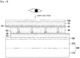
- the light route control member 1000 may be disposed on or under display panel 2000.
- the display panel 2000 and the light route control member 1000 may be disposed to be adhered to each other.
- the display panel 2000 and the light route control member 1000 may be adhered to each other via an adhesive layer 1500.
- the adhesive layer 1500 may be transparent.
- the adhesive layer 1500 may include an adhesive or an adhesive layer containing an optical transparent adhesive material.
- the adhesive layer 1500 may include a release film.
- the light route control member and the display panel may be adhered after the release film is removed.
- one end or one end and the other end of the light route control member may protrude, and the light conversion part may not be disposed on the protruding portion.
- the protrusion region is an electrode connection portion, and may connect an external printed circuit board and the light route control member through the electrode connection portion.
- the display panel 2000 may include a first substrate 2100 and a second substrate 2200.
- the light route control member may be formed under the liquid crystal panel. That is, when the user-viewed side of the liquid crystal panel is defined as the upper portion of the liquid crystal panel, the light route control member may be disposed under the liquid crystal panel.
- the display panel 2000 may be formed in a structure in which the first substrate 2100 including a thin film transistor (TFT) and a pixel electrode and the second substrate 2200 including color filter layers are bonded with a liquid crystal layer interposed therebetween.
- TFT thin film transistor
- the display panel 2000 may be a liquid crystal display panel of a color filter on transistor (COT) structure in which a thin film transistor, a color filter, and a black matrix are formed at the first substrate 2100 and the second substrate 2200 is bonded to the first substrate 2100 with the liquid crystal layer interposed therebetween. That is, a thin film transistor may be formed on the first substrate 2100, a protective film may be formed on the thin film transistor, and a color filter layer may be formed on the protective film. In addition, a pixel electrode in contact with the thin film transistor may be formed on the first substrate 2100. At this point, in order to improve an aperture ratio and simplify a masking process, the black matrix may be omitted, and a common electrode may be formed to function as the black matrix.
- COT color filter on transistor
- the display device may further include a backlight unit providing light from a rear surface of the display panel 2000.
- the light route control member is disposed below the liquid crystal panel and above the backlight unit 3000, and the light route control member may be disposed between the backlight unit 3000 and the display panel 2000.
- the light route control member may be formed on the organic light emitting diode panel. That is, when the surface viewed by the user of the organic light emitting diode panel is defined as the upper portion of the organic light emitting diode panel, the light route control member may be disposed on the organic light emitting diode panel.
- the display panel 2000 may include a self-luminous element that does not require a separate light source.
- a thin film transistor may be formed on the first substrate 2100, and an organic light emitting element in contact with the thin film transistor may be formed.
- the organic light emitting element may include an anode, a cathode, and an organic light emitting layer formed between the anode and the cathode. Further, the second substrate 2200 configured to function as an encapsulation substrate for encapsulation may further be included on the organic light emitting element.
- the light emitted from the display panel 2000 or the backlight unit 3000 may move from the second substrate 120 of the light route control member to the first substrate 110.
- a polarizing plate may be further disposed between the light route control member 1000 and the display panel 2000.
- the polarizing plate may be a linear polarizing plate or an external light reflection preventive polarizing plate.
- the polarizing plate may be the linear polarizing plate.
- the polarizing plate may be the external light reflection preventive polarizing plate.
- an additional functional layer 1300 such as an anti-reflection layer, an anti-glare, or the like may be further disposed on the light route control member 1000.
- the functional layer 1300 may be adhered to one surface of first substrate 110 of the light route control member.
- the functional layer 1300 may be adhered to the first substrate 110 of the light route control member via an adhesive layer.
- a release film for protecting the functional layer may be further disposed on the functional layer 1300.
- the light route control member is disposed at an upper portion of the display panel, but the embodiment is not limited thereto, and the light route control member may be disposed at various positions such as a position in which light is adjustable, that is, a lower portion of the display panel, between a second substrate and a first substrate of the display panel, or the like.
- the light route control member according to the embodiment may be applied to various display devices.
- the light route control member according to the embodiment may be applied to a display device that displays a display.
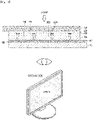
- the receiving unit when power is not applied to the light route control member as shown in FIG. 15 , the receiving unit functions as the light blocking part, so that the display device is driven in a light blocking mode, and when power is applied to the light route control member as shown in FIG. 16 , the receiving unit functions as the light transmitting part, so that the display device may be driven in an open mode.
- a user may easily drive the display device in a privacy mode or a normal mode according to application of power.
- the light emitted from the backlight unit or the self-luminous device may move from the first substrate to the second substrate.
- the light emitted from the backlight unit or the self-luminous device may also move from the second substrate to the first substrate.
- the display device to which the light route control member according to the embodiment is applied may also be applied inside the vehicle.
- the display device including the light route control member may display a video confirming information of the vehicle and a movement route of the vehicle.
- the display device may be disposed between a driver seat and a passenger seat of the vehicle.
- the light route control member according to the embodiment may be applied to a dashboard that displays a speed, an engine, an alarm signal, and the like of the vehicle.
- the light route control member according to the embodiment may be applied to a front glass (FG) of the vehicle or right and left window glasses.
Landscapes
- Physics & Mathematics (AREA)
- Nonlinear Science (AREA)
- General Physics & Mathematics (AREA)
- Optics & Photonics (AREA)
- Engineering & Computer Science (AREA)
- Structural Engineering (AREA)
- Chemical & Material Sciences (AREA)
- Crystallography & Structural Chemistry (AREA)
- Architecture (AREA)
- Civil Engineering (AREA)
- Electrochromic Elements, Electrophoresis, Or Variable Reflection Or Absorption Elements (AREA)
Abstract
Description
- An embodiment relates to a light route control member, and a display device including the same.
- A light-shielding film shields transmitting of light from a light source, and is attached to a front surface of a display panel which is a display device used for a mobile phone, a notebook, a tablet PC, a vehicle navigation device, a vehicle touch, etc., so that the light-shielding film adjusts a viewing angle of light according to an incident angle of light to express a clear image quality at a viewing angle needed by a user when the display transmits a screen.
- In addition, the light-shielding film may be used for the window of a vehicle, building or the like to shield outside light partially to prevent glare, or to prevent the inside from being visible from the outside.
- That is, the light-shielding film may be a light route control member that controls a movement path of light, block light in a specific direction, and transmit light in a specific direction. Accordingly, by controlling the light transmission angle by the light-shielding film, it is possible to control the viewing angle of the user.
- Meanwhile, such a light-shielding film may be a light-shielding film that can always control the viewing angle regardless of the surrounding environment or the user's environment, and switchable light-shielding film that allows the user to turn on/off the viewing angle control according to the surrounding environment or the user's environment may be distinguished.
- Such a switchable light-shielding film may be implemented by adding electrically moving particles to the pattern part and changing the pattern part into a light transmitting portion and a light blocking portion by dispersion and aggregation of the particles.
- Meanwhile, the pattern part may be divided into a plurality of pattern part by a plurality of partition wall parts disposed between the pattern parts.
- The pattern part may be formed by forming the shape of the pattern part in a resin material using a mold, and filling the formed pattern part with a dispersion in which light conversion particles are dispersed.
- At this time, due to the nature of the molding process, the pattern part is formed while extending from the lower part to the upper part and having an inclined surface with a larger width. Accordingly, there is a problem in that the light movement path is reduced by the width of the pattern part above the pattern part from which the light is emitted, so that the front luminance of the light route control member is reduced.
- Accordingly, there is a need for a light route control member having a new structure that can solve the decrease in front luminance according to the inclined surfaces and inclination angles of the partition wall part and the pattern part as described above.
- An embodiment relates to the light route control member having improved front transmittance and side shielding characteristics by controlling the inclination angle of a pattern part and a partition wall part, and a display device including the same.
- A light route control member according to an embodiment includes: a first substrate; a first electrode disposed on the first substrate; a second substrate disposed on the first substrate; a second electrode disposed under the second substrate; and a light conversion part disposed between the first electrode and the second electrode, wherein the light conversion part comprises a partition wall part and a receiving part alternately arranged, and the light transmittance of the receiving part is changed according to application of a voltage, and the receiving part includes a dispersion and light conversion particles dispersed in the dispersion, and a contact surface of the partition wall part and the receiving part is inclined with an inclination angle with respect to a reference axis in a direction perpendicular to the upper surface of the first substrate, and the inclination angle is 2° to 10°.
- The light route control member according to the embodiment may control the widths of the upper and lower surfaces of the partition wall part and the receiving part according to the movement path of light.
- In detail, the width of the lower surface of the partition wall part through which light is incident and the upper surface of the partition wall part through which light is emitted may be different. That is, the inclined surface is formed by forming a certain inclination angle on the side surface of the partition wall part, which is the contact surface of the partition wall part and the receiving part. Accordingly, the width of the upper surface of the partition wall part through which light is emitted may be greater than the width of the lower surface of the partition wall part through which light is incident.
- Therefore, since light incident to the inside of the light route control member and emitted to the outside is emitted through the width of the upper surface of the partition wall part having a relatively large width, the front luminance of the light route control member can be improved according to the increase in the movement path of the light.
- That is, when the receiving part of the light route control member is driven by the light blocking part, the width of the area of the emitting surface in the partition wall part area through which light pass may be increased. Accordingly, the movement path of the light is increased, and thus the front luminance of the light route control member can be improved.
- In addition, by controlling the inclination angle of the partition wall part and the receiving part, it is possible to control an incident angle, a refraction angle, and total reflection according to a difference in refractive index between the partition wall part and the receiving part. Accordingly, by increasing the amount of light incident to the receiving part of the light route control member, the side shielding effect may be improved.
- In addition, by controlling the inclination angle of the partition wall part and the receiving part, it is possible to control an incident angle, a refraction angle, and total reflection according to a difference in refractive index between the partition wall part and the receiving part. Accordingly, even when the receiving part of the light route control member is driven to the light transmitting portion, loss of light can be reduced, so that the front luminance of the light route control member can be improved.
-
-
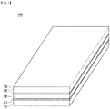
FIG. 1 is a view showing perspective view of a light route control member according to an embodiment. -
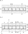
FIGS. 2 and3 are views showing perspective views of a first substrate and a first electrode and a perspective view of a second substrate and a second electrode of the light route control member according to the embodiment, respectively. -
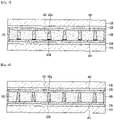
FIGS. 4 and5 are views showing cross-sectional views of the light route control member according to the embodiment. -
FIG. 6 is a view illustrating a cross-sectional view of a light route control member according to an embodiment for explaining a light path. -
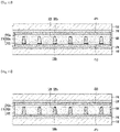
FIGS. 7 and 8 are views showing cross-sectional views of the light route control member according to another embodiment. -
FIGS. 9 to 10 are views showing cross-sectional views of the light route control member according to another embodiment. -
FIGS. 11 to 12 are views showing cross-sectional views of the light route control member according to another embodiment. -
FIGS. 13 and14 are views showing cross-sectional views of a display device to which a light route control member according to an embodiment is applied. -
FIGS. 15 to 17 are views for describing one embodiment of the display device to which the light route control member according to the embodiment is applied. - Hereinafter, embodiments of the present invention will be described in detail with reference to the accompanying drawings. However, the spirit and scope of the present invention is not limited to a part of the embodiments described, and may be implemented in various other forms, and within the spirit and scope of the present invention, one or more of the elements of the embodiments may be selectively combined and replaced.
- In addition, unless expressly otherwise defined and described, the terms used in the embodiments of the present invention (including technical and scientific terms) may be construed the same meaning as commonly understood by one of ordinary skill in the art to which this invention belongs, and the terms such as those defined in commonly used dictionaries may be interpreted as having a meaning that is consistent with their meaning in the context of the relevant art.
- In addition, the terms used in the embodiments of the present invention are for describing the embodiments and are not intended to limit the present invention. In this specification, the singular forms may also include the plural forms unless specifically stated in the phrase, and may include at least one of all combinations that may be combined in A, B, and C when described in "at least one (or more) of A (and), B, and C".
- Further, in describing the elements of the embodiments of the present invention, the terms such as first, second, A, B, (a), and (b) may be used. These terms are only used to distinguish the elements from other elements, and the terms are not limited to the essence, order, or order of the elements.
- In addition, when an element is described as being "connected", "coupled", or "connected" to another element, it may include not only when the element is directly "connected" to, "coupled" to, or "connected" to other elements, but also when the element is "connected", "coupled", or "connected" by another element between the element and other elements.
- Further, when described as being formed or disposed "on (over)" or "under (below)" of each element, the "on (over)" or "under (below)" may include not only when two elements are directly connected to each other, but also when one or more other elements are formed or disposed between two elements.
- Furthermore, when expressed as "on (over)" or "under (below)", it may include not only the upper direction but also the lower direction based on one element.
- Hereinafter, a light route control member according to an embodiment will be described with reference to drawings. The light route control member described below relates to a switchable light route control member that drives in various modes according to the movement of electrophoretic particles application of a voltage.
- Referring to
FIGS. 1 to 3 , a light route control member according to an embodiment may include afirst substrate 110, asecond substrate 120, afirst electrode 210, asecond electrode 220, and alight conversion part 300. - The
first substrate 110 may support thefirst electrode 210. Thefirst substrate 110 may be rigid or flexible. - In addition, the
first substrate 110 may be transparent. For example, thefirst substrate 110 may include a transparent substrate capable of transmitting light. - The
first substrate 110 may include glass, plastic, or a flexible polymer film. For example, the flexible polymer film may be made of any one of polyethylene terephthalate (PET), polycarbonate (PC), acrylonitrile-butadiene-styrene copolymer (ABS), polymethyl methacrylate (PMMA), polyethylene naphthalate (PEN), polyether sulfone (PES), cyclic olefin copolymer (COC), triacetylcellulose (TAC) film, polyvinyl alcohol (PVA) film, polyimide (PI) film, and polystyrene (PS), which is only an example, but the embodiment is not limited thereto. - In addition, the
first substrate 110 may be a flexible substrate having flexible characteristics. - Further, the
first substrate 110 may be a curved or bended substrate. That is, the light route control member including thefirst substrate 110 may also be formed to have flexible, curved, or bent characteristics. Accordingly, the light route control member according to the embodiment may be changed to various designs. - The
first substrate 110 may have a thickness of 30um to 80um. - The
first electrode 210 may be disposed on one surface of thefirst substrate 110. In detail, thefirst electrode 210 may be disposed on an upper surface of thefirst substrate 110. That is, thefirst electrode 210 may be disposed between thefirst substrate 110 and thesecond substrate 120. - The
first electrode 210 may contain a transparent conductive material. For example, thefirst electrode 210 may contain a metal oxide such as indium tin oxide, indium zinc oxide, copper oxide, tin oxide, zinc oxide, titanium oxide, etc. - The
first electrode 210 may be disposed on thefirst substrate 110 in a film shape. In detail, light transmittance of thefirst electrode 210 may be about 80% or more. - The
first electrode 210 may have a thickness of about 0.1um to about 0.5um. - Alternatively, the
first electrode 210 may contain various metals to realize low resistance. For example, thefirst electrode 210 may contain at least one metal of chromium (Cr), nickel (Ni), copper (Cu), aluminum (Al), silver (Ag), molybdenum (Mo). gold (Au), titanium (Ti), and alloys thereof. - The
first electrode 210 may be disposed on the entire surface of one surface of thefirst substrate 110. In detail, thefirst electrode 210 may be disposed as a surface electrode on one surface of thefirst substrate 110. However, the embodiment is not limited thereto, and thefirst electrode 210 may be formed of a plurality of pattern electrodes having a predetermined pattern. - For example, the
first electrode 210 may include a plurality of conductive patterns. In detail, thefirst electrode 210 may include a plurality of mesh lines intersecting each other and a plurality of mesh openings formed by the mesh lines. - Accordingly, even though the
first electrode 210 contains a metal, visibility may be improved because the first electrode is not visible from the outside. In addition, the light transmittance is increased by the openings, so that the brightness of the light route control member according to the embodiment may be improved. - The
second substrate 120 may be disposed on thefirst substrate 110. In detail, thesecond substrate 120 may be disposed on thefirst electrode 210 on thefirst substrate 110. - The
second substrate 120 may contain a material capable of transmitting light. Thesecond substrate 120 may contain a transparent material. Thesecond substrate 120 may contain a material the same as or similar to that of thefirst substrate 110 described above. - For example, the
second substrate 120 may include glass, plastic, or a flexible polymer film. For example, the flexible polymer film may be made of any one of polyethylene terephthalate (PET), polycarbonate (PC), acrylonitrile-butadiene-styrene copolymer (ABS), polymethyl methacrylate (PMMA), polyethylene naphthalate (PEN), polyether sulfone (PES), cyclic olefin copolymer (COC), triacetylcellulose (TAC) film, polyvinyl alcohol (PVA) film, polyimide (PI) film, and polystyrene (PS), which is only an example, but the embodiment is not limited thereto. - In addition, the
second substrate 120 may be a flexible substrate having flexible characteristics. - Further, the
second substrate 120 may be a curved or bended substrate. That is, the light route control member including thesecond substrate 120 may also be formed to have flexible, curved, or bent characteristics. Accordingly, the light route control member according to the embodiment may be changed to various designs. - The
second substrate 120 may have a thickness of 30mm to 80mm. - The
second electrode 220 may be disposed on one surface of thesecond substrate 120. In detail, thesecond electrode 220 may be disposed on a lower surface of thesecond substrate 120. That is, thesecond electrode 220 may be disposed on a surface on which thesecond substrate 120 faces thefirst substrate 110. That is, thesecond electrode 220 may be disposed facing thefirst electrode 210 on thefirst substrate 110. That is, thesecond electrode 220 may be disposed between thefirst electrode 210 and thesecond substrate 120. - The
second electrode 220 may contain a transparent conductive material. For example, thesecond electrode 220 may contain a metal oxide such as indium tin oxide, indium zinc oxide, copper oxide, tin oxide, zinc oxide, titanium oxide, etc. - The
second electrode 220 may be disposed on thefirst substrate 110 in a film shape. In addition, the light transmittance of thesecond electrode 220 may be about 80% or more. - The
second electrode 220 may have a thickness of about 0.1um to about 0.5um. - Alternatively, the
second electrode 220 may contain various metals to realize low resistance. For example, thesecond electrode 220 may contain at least one metal of chromium (Cr), nickel (Ni), copper (Cu), aluminum (Al), silver (Ag), molybdenum (Mo). gold (Au), titanium (Ti), and alloys thereof. - The
second electrode 220 may be disposed on the entire surface of one surface of thesecond substrate 120. In detail, thesecond electrode 220 may be disposed as a surface electrode on one surface of thesecond substrate 120. However, the embodiment is not limited thereto, and thesecond electrode 220 may be formed of a plurality of pattern electrodes having a predetermined pattern. - For example, the
second electrode 220 may include a plurality of conductive patterns. In detail, thesecond electrode 220 may include a plurality of mesh lines intersecting each other and a plurality of mesh openings formed by the mesh lines. - Accordingly, even though the
second electrode 220 contains a metal, visibility may be improved because thesecond electrode 220 is not visible from the outside. In addition, the light transmittance is increased by the openings, so that the brightness of the light route control member according to the embodiment may be improved. - The
light conversion part 300 may be disposed between thefirst substrate 110 and thesecond substrate 120. In detail, thelight conversion part 300 may be disposed between thefirst electrode 210 and thesecond electrode 220. - An adhesive layer 400 may be disposed at least one of between the
light conversion part 300 and thefirst substrate 110 and between thelight conversion part 300 and thesecond substrate 120, and thefirst substrate 110, thesecond substrate 120, and thelight conversion part 300 may be adhered to each other by the adhesive layer 400. - Referring to
FIGS. 4 and5 , theadhesive layer 410 is disposed between thefirst electrode 210 and thelight conversion par 300, whereby thelight conversion part 300 and thefirst electrode 210 may be adhered to each other. - In addition, a
buffer layer 420 for improving adhesion between thelight conversion part 300 and thefirst electrode 210 is disposed between thelight conversion part 300 and thesecond electrode 220, and thelight conversion unit 300 and thesecond electrode 220, which are different materials, may be easily bonded through thebuffer layer 420. - The
light conversion part 300 may include apartition wall part 310 and a receivingpart 320. - The
partition wall part 310 may be defined as a partition wall region that partitions the receiving part. That is, thepartition wall part 310 is a partition wall region partitioning a plurality of receiving parts. And the receivingpart 320 may be defined as a region that changes into a light blocking part and a light transmitting part according to the application of a voltage. - The
partition wall part 310 and the receivingpart 320 may be alternately disposed with each other. Thepartition wall part 310 and the receivingpart 320 may be disposed to have different widths. For example, the width of thepartition wall portion 310 may be greater than the width of the receivingpart 320. - The
partition wall part 310 and the receivingpart 320 may be alternately disposed with each other. In detail, thepartition wall part 310 and the receivingpart 320 may be alternately disposed with each other. That is, each of thepartition wall portions 310 may be disposed between the receivingparts 320 adjacent to each other, and each of the receivingparts 320 may be disposed between the adjacentpartition wall portions 310. - The
partition wall part 310 may contain a transparent material. Thepartition wall part 310 may contain a material that may transmit light. - The
partition wall part 310 may contain a resin material. Thepartition wall part 310 may contain a photo-curable resin material. As an example, thepartition wall part 310 may contain a UV resin or a transparent photoresist resin. Alternatively, thepartition wall part 310 may contain urethane resin or acrylic resin. - The
partition wall part 310 may transmit light incident on any one of thefirst substrate 110 and thesecond substrate 120 toward another substrate. - For example, in
FIGS. 4 and5 , light may be emitted in the direction of thesecond substrate 120 and may be incident in the direction of thefirst substrate 110. Thepartition wall part 310 transmits the light, and the transmitted light may move in the direction of thesecond substrate 120. - A sealing
part 500 sealing the light route control member may be disposed on a side surface of the partition wall part, and a side surface of thelight conversion part 300 may be sealed by the sealing part. - The receiving
part 320 may include a light conversion material 330 including adispersion 320a andlight conversion particles 320b. In detail, thedispersion 320a may be filled in the receivingpart 320, and a plurality oflight conversion particles 320b may be dispersed in the dispersion 330a. - The
dispersion 320a may be a material for dispersing thelight conversion particles 320b. Thedispersion 320a may contain a transparent material. Thedispersion 320a may contain a non-polar solvent. In addition, thedispersion 320a may contain a material capable of transmitting light. For example, thedispersion 320a may include at least one of a halocarbon-based oil, a paraffin-based oil, and isopropyl alcohol. - The
light conversion particles 320b may be disposed to be dispersed in the dispersion 330a. In detail, the plurality oflight conversion particles 320b may be disposed to be spaced apart from each other in the dispersion 330a. - The
light conversion particles 320b may include a material capable of absorbing light. That is, thelight conversion particle 320b may be a light absorbing particle. Thelight conversion particle 320b may have a color. For example, thelight conversion particles 320b may have a black-based color. For example, thelight conversion particles 320b may include carbon black particles. - The surface of the
light conversion particle 320b may be charged. Accordingly, according to the application of the voltage, thelight conversion particles 320b may move in one direction. - The light transmittance of the receiving
part 320 may be changed by thelight conversion particles 320b. In detail, the receivingpart 320 may be changed into a light blocking part and a light transmitting part by changing the light transmittance by thelight conversion particles 320b. That is, the receivingpart 320 may change the transmittance of the light passing through the receivingpart 320 by dispersion and aggregation of thelight conversion particles 320b disposed therein in thedispersion 320a. - For example, the light path member according to the embodiment may be change from the first mode to the second mode or from the second mode to the first mode by a voltage applied to the
first electrode 210 and thesecond electrode 220. - In detail, in the light
route control member 1000 according to the embodiment, the receivingpart 320 becomes the light blocking part in the first mode, and light of a specific angle may be blocked by the receivingpart 320. That is, a viewing angle of the user viewing from the outside may be narrowed. - In addition, in the light
route control member 1000 according to the embodiment, the receivingpart 320 becomes the light transmitting part in the second mode, and in the light route control member according to the embodiment, light may be transmitted through both thepartition wall part 310 and the receivingpart 320. That is, the viewing angle of the user viewing from the outside may be widened. - Switching from the first mode to the second mode, that is, the conversion of the receiving
part 320 from the light blocking part to the light transmitting part may be realized by movement of thelight conversion particles 320b of the receivingpart 320. That is, thelight conversion particles 320b have electric charges on their surface, and may move in the direction of thefirst electrode 210 or thesecond electrode 220 by an applied voltage or by characteristics of the charge. That is, thelight conversion particles 320b may be electrophoretic particles. - In detail, the receiving
part 320 may be electrically connected to thefirst electrode 210 and thesecond electrode 220. - In this case, when a voltage is not applied to the light route control member from the outside, the
light conversion particles 320b of the receivingpart 320 are uniformly dispersed in the dispersion 330a, and light may be blocked by the light conversion particles in the receivingpart 320. Accordingly, in the first mode, the receivingpart 320 may be driven as the light blocking part. - Alternatively, when a voltage is applied to the light route control member from the outside, the
light conversion particles 320b may move. For example, thelight conversion particles 320b may move toward one end or the other end of the receivingpart 320 by a voltage transmitted through thefirst electrode 210 and thesecond electrode 220. That is, thelight conversion particles 320b may move from the receivingpart 320 toward the first electrode or the second electrode. - In detail, when a voltage is applied to the
first electrode 210 and/or thesecond electrode 220, an electric field is formed between thefirst electrode 210 and thesecond electrode 220. And, thelight conversion particles 320b in a negatively charged state can be moved in the direction of the positively charged electrode among thefirst electrode 210 and thesecond electrode 220 using thedispersion 320a as a medium. - In detail, when a voltage is applied to the
first electrode 210 and/or thesecond electrode 220, an electric field is formed between thefirst electrode 210 and thesecond electrode 220, and the charged carbon black, that is, the light conversion particles may be moved toward a positive electrode of thefirst electrode 210 and thesecond electrode 220 using thedispersion 320a as a medium. - That is, when the voltage is applied to the
first electrode 210 and/or thesecond electrode 220, as shown inFIG. 4 , thelight conversion particles 320b may be moved toward thefirst electrode 210 in the dispersion 330a. That is, thelight conversion particles 320b are moved in one direction, and the receivingpart 320 may be driven as the light transmitting part. - In addition, when the voltage is not applied to the
first electrode 210 and/or thesecond electrode 220, as shown inFIG. 5 , thelight conversion particles 320b may be uniformly dispersed in thedispersion 320a to drive the receiving part 30202 as the light blocking part. - Accordingly, the light route control member according to the embodiment may be driven in two modes according to a user's surrounding environment. That is, when the user requires light transmission only at a specific viewing angle, the receiving unit is driven as the light blocking part, or in an environment in which the user requires high brightness, a voltage may be applied to drive the receiving unit as the light transmitting part.
- Therefore, since the light route control member according to the embodiment may be implemented in two modes according to the user's requirement, the light route control member may be applied regardless of the user's environment.
- Meanwhile, in the light route control member according to the embodiment, the
partition wall part 310 and the receivingpart 320 may have opposite shapes. - In detail, when the surface where the
partition wall part 310 and thefirst electrode 210 contact is defined as the lower surface of the partition wall part, and the opposite surface is defined as the upper surface of the partition wall part, a width W2a of a lower surface of the partition wall part may be smaller than a width W2b of an upper surface of the partition wall part. - In addition, when a surface in which the receiving
part 320 and thefirst electrode 210 contact is defined as the lower surface of the receiving part and the opposite surface is defined as the upper surface of the receiving part, a width of the lower surface W1a of the receiving part may be greater than the width W1b of the upper surface of the receiving part. - For example, assuming that light is incident on the lower surface of the
first substrate 110 and the light is emitted toward the upper surface of thesecond substrate 120, the partition wall part has a width of the incident surface greater than a width of the light emitting surface, and the receiving part have a width of the emitting surface smaller than a width of the light incident surface - That is, in the
partition wall part 310, a width W2b of an upper surface of the partition wall part from which the light is emitted is greater than a width W2a of a lower surface through which the light is incident. And, in the receivingpart 320, a width W1b of an upper surface of the receiving part from which the light is emitted may be smaller than a width W1a of a lower surface through which the light is incident. - That is, the width W2b of the upper surface of the
partition wall part 310 may be greater than the width W2a of the lower surface of partition wall part facing the display panel from which the light is emitted. - Accordingly, in the first mode (that is, when a voltage is applied and the
light conversion particles 320b are dispersed in thedispersion 320a, the receivingprat 320 is driven as a light blocking part) of the light route control member according to the embodiment, the front luminance of the light route control member may be improved. - That is, when the light route control member is driven in the first mode, the area from which the light is emitted from the light route control member is the area of the
partition wall part 310. In this case, by increasing the width of the upper surface of the partition wall part from which the light is emitted, the amount of light emitted toward thesecond substrate 120 may be increased. - Accordingly, the light route control member according to the embodiment may increase the amount of emitted light, thereby improving the front luminance of the light route control member.
- Meanwhile, referring to
FIG. 6 , in the light route control member according to the embodiment, thepartition wall part 310 and the receivingpart 320 may have inclined surfaces. In detail, thepartition wall part 310 and the receivingpart 320 may include surfaces in contact with each other, and the contact surfaces CS of thepartition wall part 310 and the receivingpart 320 may have inclined surfaces. That is, the contact surface may be an inclined surface of thepartition wall part 310 and an inclined surface of the receivingpart 320. - In detail, the
partition wall part 310 or the receivingpart 320 may include an inclined surface having an inclination angle θ with respect to the reference axis AX, which is a direction perpendicular to the upper surface of thefirst substrate 110. - In this case, the widths of the inclined surfaces facing each other may be inclined so that the width of the partition wall part increases while extending from the lower surface of the partition wall part toward the upper surface of the partition wall part.
- Alternatively, the widths of the inclined surfaces facing each other may be inclined so that the width of the receiving part decreases while extending from the lower surface of the receiving part toward the upper surface of the receiving part.
- In addition, the inclined surface may be inclined such that the width of the partition wall part increases and the width of the receiving part decreases while extending in the movement direction of the light.
- For example, the contact surface CS, which is an inclined surface of the
partition wall part 310 and the receivingpart 320, may be inclined while having an inclination angle of 10° or less from the reference axis AX, which is a direction perpendicular to the upper surface of thefirst substrate 110. In detail, the inclined surface of thepartition wall part 310 or the receivingpart 320 may be inclined while having an inclination angle of 5° or less from the reference axis AX, which is a direction perpendicular to the upper surface of thefirst substrate 110. In more detail, the inclined surface of thepartition wall part 310 or the receivingpart 320 may be inclined while having an inclination angle of 3° or less from the reference axis AX, which is a direction perpendicular to the upper surface of thefirst substrate 110. In more detail, the inclined surface of thepartition wall part 310 or the receivingpart 320 may be inclined while having an inclination angle of 1° to 3° from the reference axis AX, which is a direction perpendicular to the upper surface of thefirst substrate 110. - It is difficult to implement the inclination angle of the
partition wall part 310 or the receivingpart 320 at an inclination angle of less than 1° with the reference axis AX, which is a direction perpendicular to the upper surface of thefirst substrate 110. That is, an imprinting process is performed to form the partition wall part and the receiving part. Due to the characteristics of the mold for forming the partition wall part and the receiving part and materials constituting the partition wall part, the partition wall part and the receiving part have inclined surfaces of a certain inclination angle. At this time, it may be difficult to form the inclined surface of thepartition wall part 310 or the receivingpart 320 at an inclination angle of less than 2° with the reference axis AX, which is a direction perpendicular to the upper surface of thefirst substrate 110. - In addition, when the inclined surface of the
partition wall part 310 or the receivingpart 320 has an inclination angle exceeding 10° with the reference axis AX, which is a direction perpendicular to the upper surface of thefirst substrate 110, the amount of emitted light of the light route control member may be reduced, and thus the front luminance of the light route control member may be reduced. - The
partition wall part 310 and the receivingpart 320 may have different refractive indices. - In detail, the refractive index of the
partition wall part 310 may be 1.64 or less. In detail, the refractive index of thepartition wall part 310 may be 1.36 to 1.64. The refractive index of thepartition wall part 310 may correspond to the refractive index of the resin composition constituting the partition wall part. - In addition, the refractive index of the receiving
part 320 may be 1.45 or less. In detail, the refractive index of the receivingpart 320 may be 1.42 to 1.45. The refractive index of the receivingpart 320 may correspond to the refractive index of thedispersion 320a contained in the receivingpart 320. - That is, the refractive index of the
partition wall part 310 may be relatively larger than that of the receivingpart 320. - Accordingly, the light moving from the
first substrate 110 to thesecond substrate 120 direction may have different characteristics when it moves from thepartition wall part 310 to the receivingpart 320 and when it moves from the receivingpart 320 to thepartition wall part 310. - For example, an incident angle θ1 of the first light L1 moving from the
partition wall part 310 to the receivingpart 320 and an incident angle θ2 of the second light L2 moving from the receivingpart 320 to partitionwall part 310 may be different. - That is, the first light L1 moving from a region having a large refractive index to a region having a small refractive index may have a small incident angle, and the second light L2 moving from the area having the small refractive index to the area having the large refractive index may have a relatively larger incident angle than the first light L1.
- In this case, an inclined surface having a predetermined angle may be formed on the
partition wall part 310 and the receivingpart 320. Accordingly, the incident angle of the second light L2 moving from the region having the small refractive index to the region having the large refractive index, that is, moving from the receivingpart 320 to thepartition wall part 310 may be reduced. - Accordingly, total reflection of the second light L2 may be reduced, and light loss due to total reflection may be reduced, thereby improving the front luminance of the light route control member.
- That is, since the refractive index of the
partition wall part 310 is greater than that of the receivingpart 320, the light loss due to total reflection may be greater for the second light L2 than the first light L1. Accordingly, by minimizing the incident angle of the second light L2, total reflection may be reduced. Accordingly, the front luminance of the light route control member in the second mode can be improved. - In addition, by forming an inclined surface of a predetermined angle in the above shape on the
partition wall part 310 and the receivingpart 320, the amount of incident light incident into the receivingpart 320 may be increased. Accordingly, the side shielding effect in the first mode can be improved. - The
partition wall part 310 and the receivingpart 320 may be disposed to have different widths. - In detail, the width W2a of the lower surface of the partition wall part and the width W1a of the lower surface of the receiving part may be different from each other. Alternatively, the width W2b of the upper surface of the partition wall part and the width W1b of the upper surface of the receiving part may be different from each other.
- In detail, the maximum width of the receiving part may be about 10% to 40% of the sum of the widths of the receiving part and the partition wall part, and the maximum width of the partition wall part may be about 60% to 90% of the sum of the widths of the receiving part and the partition wall part.
- When the maximum width of the receiving part exceeds 40% of the sum of the widths of the receiving part and the partition wall part, the receiving part may be visually recognized from the outside, and thus the visibility of the light route control member may be reduced. In addition, when the maximum width of the receiving part is less than 10% of the sum of the widths of the receiving part and the partition wall, the width of the receiving part is too narrow, and a defect may occur when injecting the dispersion into the receiving part.
- For example, the sum of the width W2a of the lower surface of the partition wall part and the width W1a of the lower surface of the receiving part or the sum of the width W2b of the upper surface of the partition wall part and the width W1b of the upper surface of the receiving part may be about 100 µm.
- When the sum of the width W2a of the lower surface of the partition wall part and the width W1a of the lower surface of the receiving part or when the sum of the width W2b of the upper surface of the partition wall part and the width W1b of the upper surface of the receiving part exceeds 100 µm, it is difficult to arrange a plurality of receiving part in the light route control member, and the spacing between the receiving part may be reduced, so that the side shielding effect may be reduced.
-
FIGS. 7 to 8 are views illustrating other cross-sectional views of the light route control member according to the embodiment. - Referring to
FIGS. 7 and 8 , in the light route control member according to the embodiment, the receivingpart 320 may be disposed in contact with the electrode differently fromFIGS. 4 and5 . - For example, the receiving
part 320 may be disposed in direct contact with thefirst electrode 210. - Accordingly, the
first electrode 210 and the receivingpart 320 are not spaced apart, but are disposed in direct contact with each other. Accordingly, the voltage applied from thefirst electrode 2100 may be easily transmitted to the receivingpart 320. - Accordingly, since the moving speed of the
light conversion particle 320b inside the receivingpart 320 can be improved, the driving characteristics of the light route control member can be improved. - The light route control member according to the embodiment may control the widths of the upper and lower surfaces of the partition wall part and the receiving part according to the movement path of light.
- In detail, the width of the lower surface of the partition wall part through which light is incident and the upper surface of the partition wall part through which light is emitted may be different. That is, the inclined surface is formed by forming a certain inclination angle on the side surface of the partition wall part, which is the contact surface of the partition wall part and the receiving part. Accordingly, the width of the upper surface of the partition wall part through which light is emitted may be greater than the width of the lower surface of the partition wall part through which light is incident.
- Therefore, since light incident to the inside of the light route control member and emitted to the outside is emitted through the width of the upper surface of the partition wall part having a relatively large width, the front luminance of the light route control member can be improved according to the increase in the movement path of the light.
- That is, when the receiving part of the light route control member is driven by the light blocking part, the width of the area of the emitting surface in the partition wall part area through which light pass may be increased. Accordingly, the movement path of the light is increased, and thus the front luminance of the light route control member can be improved.
- In addition, by controlling the inclination angle of the partition wall part and the receiving part, it is possible to control an incident angle, a refraction angle, and total reflection according to a difference in refractive index between the partition wall part and the receiving part. Accordingly, by increasing the amount of light incident to the receiving part of the light route control member, the side shielding effect may be improved.
- In addition, by controlling the inclination angle of the partition wall part and the receiving part, it is possible to control an incident angle, a refraction angle, and total reflection according to a difference in refractive index between the partition wall part and the receiving part. Accordingly, even when the receiving part of the light route control member is driven to the light transmitting portion, loss of light can be reduced, so that the front luminance of the light route control member can be improved.
- Hereinafter, the present invention will be described in more detail through the transmittance of the light route control member according to the embodiments. These embodiments are merely presented as examples in order to explain the present invention in more detail. Therefore, the present invention is not limited to these examples.
- The light path control member described above is manufactured.
- In detail, the first electrode was disposed on the first substrate, and the second electrode was disposed on the second substrate. Then, a light conversion part including a partition wall part and a receiving part was disposed on the first electrode and adhered, and the second substrate and the second electrode is disposed and adhered on the light conversion part to form a light route control member.
- In this case, the contact surface of the partition wall part and the receiving part is formed as an inclined surface having an inclination angle.
- While extending in the direction of the emitted light from the incident light passing through the light path control member, the inclined surface is inclined so that the width of the receiving part is narrowed, that is, the width of the partition wall part is widened.
- Then, the front transmittance and the side transmittance of the light route control member are measured.
- The light route control member was manufactured in the same manner as in Example.
- In this case, the contact surface of the partition wall part and the receiving part is formed as an inclined surface having an inclination angle.
- While extending in the direction of the emitted light from the incident light passing through the light path control member, the inclined surface is inclined so that the width of the receiving part is widened, that is, the width of the partition wall part is narrowed.
- Then, the front transmittance and the side transmittance of the light route control member are measured.
[Table 1] Front transmittance Minimum Average Maximum Examples 70.0% 78.5% 86.0% Comparative Example 57.1% 66.0% 71.3% [Table 2] Side transmittance Minimum Average Maximum Examples 0.7% 2.6% 6.4% Comparative Examples 1.1% 3.2% 7.1% - Referring to Tables 1 and 2, the light route control member according to the embodiment has a higher front transmittance and lower side transmittance than the light route control member according to the comparative example.
- That is, the light route control member according to the embodiment has better front luminance and side shielding effect than the light route control member according to the comparative example.
- That is, the light route control member according to the embodiment may improve the front luminance and side shielding effect compared to the light route control member by controlling the shapes and inclination angles of the inclined surfaces of the partition wall part and the receiving part.
- Hereinafter, the light route control member according to another embodiment will be described with reference to
FIGS. 9 to 12 . In the description of the light route control member according to another embodiment, descriptions that are similar to those of the light route control member according to the above-described embodiment will be omitted, and the same reference numerals will be given to the same components. - Referring to
FIGS. 9 to 12 , in the light route control member according to another embodiment, the surface resistance and the volume resistance of thepartition wall part 310 may be controlled in order to implement the improved characteristics of the light conversion part. - In detail, the
partition wall part 310 may have a high volume resistance while having a low surface resistance. - The surface resistance of the
partition wall part 310 may be controlled by adding a charged particle agent to the inside of thepartition wall part 310. In detail, thepartition wall part 310 may implement a surface resistance of a certain size range by adding a certain weight % of an antistatic agent to the photocurable resin. - For example, the partition wall part may implement a surface resistance of a certain size range by adding about 0.01 wt% to 10 wt% of an antistatic agent to the entire resin composition forming the partition wall part.
- The antistatic agent may include various antistatic agents such as nano-metal particles such as carbon, ITO, ZTO, and silver, conductive polymers, and low molecular weight polymers.
- The antistatic agent may serve to reduce the surface resistance of the partition wall part by moving to the surface of the partition wall part within the resin composition forming the partition wall part.
- That is, the antistatic agent may be disposed on the surface of the partition wall part inside the partition wall part, and thus, the surface resistance of the partition wall part may be reduced while maintaining the volume resistance of the partition wall part by the antistatic agent.
- For example, the surface resistance of the
partition wall part 310 may be 1012 Ω/sq or less. In detail, the surface resistance of thepartition wall part 310 may be 105 Ω/sq to 1012 Ω/sq. The process of implementing the surface resistance of thepartition wall part 310 to be less than 105 Ω/sq may be difficult to implement. When the surface resistance of thepartition wall part 310 exceeds 1012 Ω/sq, a driving voltage for forming a potential difference between thefirst electrode 210 and thesecond electrode 220 increases due to the resistance of the partition wall part. Therefore, the driving characteristics may be reduced. - In addition, the volume resistance of the
partition wall part 310 may be 1010 Ω·cm or less. In detail, the volume resistance of thepartition wall part 310 may be 105 Ω·cm to 1010 Ω·cm, a leakage current may be increased in thepartition wall part 310 between the receivingparts 320, thereby the driving efficiency of the light route control member may be reduced. In addition, when the volume resistance of thepartition wall part 310 is formed to exceed 1010 Ω·cm, due to the resistance of the partition wall part, a driving voltage increases to form a potential difference between thefirst electrode 210 and thesecond electrode 220, and thereby, there is a problem in that driving characteristics are reduced. - That is, since the surface resistance of the partition wall part of the light route control member according to the embodiment is reduced in a certain range, a potential difference between the first electrode and the second electrode can be formed with a low driving voltage, thereby, it is possible to move the light conversion particles inside the receiving part. That is, since the surface resistance of the interface between the partition wall part and the first electrode and the interface between the partition wall part and the second electrode is reduced, it is possible to move the light conversion particles inside the receiving part with a low driving voltage.
- In addition, it is possible to minimize an increase in leakage current in the direction of the partition wall part between the receiving parts by maintaining the volume resistance of the partition wall part in a constant range.
- Accordingly, the light route control member according to the embodiment can be driven with a low driving voltage, thereby improving driving characteristics, and minimizing leakage current to reduce power consumption, thereby improving driving efficiency.
- Meanwhile, referring to
FIGS. 9 and 10 , thepartition wall part 310 may be defined as a firstpartition wall part 310a and a secondpartition wall part 310b according to positions. - For example, the first
partition wall part 310a may be defined as a region between thesecond electrode 220 and the receivingpart 320. That is, the firstpartition wall part 310a may be defined as a region between the lower surface of thesecond electrode 220 and the upper surface of the receivingpart 320 among the partition wall part areas. - Also, the second
partition wall part 310b may be defined as a region between the firstpartition wall part 310a and thefirst electrode 210. That is, the secondpartition wall part 310b may be defined as an area between the receivingparts 320 in the area between the firstpartition wall part 310a and thefirst electrode 210 among the partition wall part areas. - In addition, the first
partition wall part 310a and the secondpartition wall part 310b may be defined as relative positions of thefirst electrode 210 and thesecond electrode 220. - In detail, the first
partition wall part 310a may be defined as a partition wall part disposed closer to thesecond electrode 220 than thefirst electrode 210, and the secondpartition wall part 310b may be defined as a partition wall part disposed closer to thefirst electrode 210 than thesecond electrode 220. - For example, the first
partition wall part 310a may be a base partition wall part disposed close to the second electrode, and the secondpartition wall part 310b may be a separation partition wall part disposed close to the first electrode. - The first
partition wall part 310a and the secondpartition wall part 310b may have different resistances. In detail, the firstpartition wall part 310a and the secondpartition wall part 310b may have different volume resistances and different surface resistances. - For example, the first
partition wall part 310a and the secondpartition wall part 310b may have different surface resistances. In detail, the firstpartition wall part 310a may have a lower surface resistance than the secondpartition wall part 310b. - For example, by varying the content of the antistatic agent included in the partition wall part for each location, the surface resistance of the first
partition wall part 310a and the secondpartition wall part 310b can be controlled. - In detail, the content of the antistatic agent included in the partition wall part may be greater in the first
partition wall part 310a than the secondpartition wall part 310b. Accordingly, the surface resistance effect of the antistatic agent may be increased in the firstpartition wall part 310a. - Accordingly, by reducing the surface resistance of the first
partition wall part 310a, the resistance between thefirst electrode 210 and thesecond electrode 220 can be reduced. Accordingly, a potential difference between thefirst electrode 210 and thesecond electrode 220 may be realized with a low driving voltage. - Also, the first
partition wall part 310a and the secondpartition wall part 310b may have different volume resistances. In detail, the secondpartition wall part 310b may have a higher volume resistance than the firstpartition wall part 310a. - Alternatively, the first
partition wall part 310a and the secondpartition wall part 310b may have the same or similar volume resistance. - That is, the first
partition wall part 310a and the secondpartition wall part 310b may have the same or different resistances in a volume resistance range of 1015Ω·cm to 1019Ω·cm. - Accordingly, it is possible to increase the volume resistance of the partition wall part between the receiving part, thereby reducing the leakage current flowing from the receiving part to the partition wall part, thereby improving the driving efficiency of the light route control member.
- Meanwhile, referring to
FIGS. 11 and 12 , thepartition wall part 310 may be defined as a firstpartition wall part 310a, a secondpartition wall part 310b, and a third partition wall part 310c according to positions. - For example, the first
partition wall part 310a may be defined as a region between thesecond electrode 220 and the receivingpart 320. That is, the firstpartition wall part 310a may be defined as a region between the lower surface of thesecond electrode 220 and the upper surface of thepartition wall part 320 among the partition wall areas. - Also, the second
partition wall part 310b and the third partition wall part 310c may be defined as a region between the firstpartition wall part 310a and thefirst electrode 210. That is, the secondpartition wall part 310b and the third partition wall part 310c may be defined as an area between the receivingpart 320 at between the firstpartition wall part 310a and thefirst electrode 220. - The second
partition wall part 310b may be defined as an area close to the firstpartition wall part 310a at an area between receiving part, and the third partition wall part 310c may be defined as an area close to thefirst electrode 210 at an area between receiving part. - In addition, the first
partition wall part 310a, the secondpartition wall part 310b, and the third partition wall part 310c may be defined as relative positions with thefirst electrode 210 and thesecond electrode 220. - In detail, the first
partition wall part 310a may be defined as a partition wall part disposed closer to thesecond electrode 220 than thefirst electrode 210, the secondpartition wall part 310b and the third partition wall part 310c may be defined as partition wall parts disposed closer to thefirst electrode 210 than thesecond electrode 220, and the third partition wall part 310c may be defined as a partition wall part disposed closer to thefirst electrode 210 than the second partition wall part. - For example, the first
partition wall part 310a may be a base partition wall part disposed close to the second electrode, and the secondpartition wall part 310b and the third partition wall part 310c may be separation partition walls disposed close to the first electrode. - In the region between the receiving part s 320, the third partition wall part 310c may be disposed to have a thickness of 1% to 20% of the thickness of the region between the receiving parts.
- When the third partition wall part 310c is formed to a thickness of less than 1% of the thickness of the region between the receiving parts, a sufficient amount of the antistatic agent may not be disposed inside the third partition wall part 310c, so that the surface resistance of the third partition wall part 310c may increase. In addition, when the third partition wall part 310c is formed to a thickness of more than 20% of the thickness of the region between the receiving parts, the surface resistance between the receiving pars is reduced by the antistatic agent, so that a leakage current in the direction of the receiving part may be increased.
- The first
partition wall part 310a, the secondpartition wall part 310b, and the third partition wall part 310c may have different resistances. In detail, the firstpartition wall part 310a, the secondpartition wall part 310b, and the third partition wall part 310c may have different volume resistances and different surface resistances. - For example, the first
partition wall part 310a, the third partition wall part 310c, and the secondpartition wall part 310b may have different surface resistances. In detail, the firstpartition wall part 310a and the third partition wall part 310c may have a lower surface resistance than the secondpartition wall part 310b. - For example, by varying the content of the antistatic agent included in the partition wall part for each location, the surface resistance of the first
partition wall part 310a, the third partition wall portion 310c, and the secondpartition wall portion 310b may be control. - In detail, the content of the antistatic agent included in the partition wall part may be greater in the first
partition wall part 310a and the third partition wall part 310c than in the secondpartition wall part 310b. Accordingly, the surface resistance effect of the antistatic agent may be increased in the firstpartition wall portion 310a and the third partition wall portion 310c. - Accordingly, the surface resistance of the first
partition wall part 310a and the third partition wall part 310c is reduced. Accordingly, the resistance between thefirst electrode 210 and thesecond electrode 220 is reduced. Accordingly, a potential difference between thefirst electrode 210 and thesecond electrode 220 may be realized with a low driving voltage. - Also, the first
partition wall part 310a, the third partition wall part 310c, and the secondpartition wall part 310b may have different volume resistances. In detail, the secondpartition wall part 310b may have a higher volume resistance than the firstpartition wall part 310a and the third partition wall part 310c. - Alternatively, the first
partition wall part 310a, the third partition wall part 310c, and the secondpartition wall part 310b may have the same or similar volume resistance. - That is, the first
partition wall portion 310a, the third partition wall portion 310c, and the secondpartition wall portion 310b may have the same or different resistances in a volume resistance range of 1015Ω·cm to 1019Ω·cm. - Accordingly, the volume resistance of the partition wall part between the receiving parts is increased. Thereby, the leakage current that moves from the receiving parts in the direction of the partition wall part is reduced. Thereby, the driving efficiency of the light route control member can be improved.
- Hereinafter, referring to
FIGS. 13 to 17 , a display device and a display apparatus to which the light route control member according to an embodiment is applied will be described. - Referring to
FIGS. 13 and14 , the lightroute control member 1000 according to an embodiment may be disposed on or underdisplay panel 2000. - The
display panel 2000 and the lightroute control member 1000 may be disposed to be adhered to each other. For example, thedisplay panel 2000 and the lightroute control member 1000 may be adhered to each other via anadhesive layer 1500. Theadhesive layer 1500 may be transparent. For example, theadhesive layer 1500 may include an adhesive or an adhesive layer containing an optical transparent adhesive material. - The
adhesive layer 1500 may include a release film. In detail, when adhering the light route control member and the display panel, the light route control member and the display panel may be adhered after the release film is removed. - Meanwhile, referring to
FIGS. 13 and14 , one end or one end and the other end of the light route control member may protrude, and the light conversion part may not be disposed on the protruding portion. The protrusion region is an electrode connection portion, and may connect an external printed circuit board and the light route control member through the electrode connection portion. - The
display panel 2000 may include afirst substrate 2100 and asecond substrate 2200. When thedisplay panel 2000 is a liquid crystal display panel, the light route control member may be formed under the liquid crystal panel. That is, when the user-viewed side of the liquid crystal panel is defined as the upper portion of the liquid crystal panel, the light route control member may be disposed under the liquid crystal panel. Thedisplay panel 2000 may be formed in a structure in which thefirst substrate 2100 including a thin film transistor (TFT) and a pixel electrode and thesecond substrate 2200 including color filter layers are bonded with a liquid crystal layer interposed therebetween. - In addition, the
display panel 2000 may be a liquid crystal display panel of a color filter on transistor (COT) structure in which a thin film transistor, a color filter, and a black matrix are formed at thefirst substrate 2100 and thesecond substrate 2200 is bonded to thefirst substrate 2100 with the liquid crystal layer interposed therebetween. That is, a thin film transistor may be formed on thefirst substrate 2100, a protective film may be formed on the thin film transistor, and a color filter layer may be formed on the protective film. In addition, a pixel electrode in contact with the thin film transistor may be formed on thefirst substrate 2100. At this point, in order to improve an aperture ratio and simplify a masking process, the black matrix may be omitted, and a common electrode may be formed to function as the black matrix. - In addition, when the
display panel 2000 is the liquid crystal display panel, the display device may further include a backlight unit providing light from a rear surface of thedisplay panel 2000. - That is, as shown in
FIG. 13 , the light route control member is disposed below the liquid crystal panel and above thebacklight unit 3000, and the light route control member may be disposed between thebacklight unit 3000 and thedisplay panel 2000. - Alternatively, as shown in
FIG. 14 , when thedisplay panel 2000 is an organic light emitting diode panel, the light route control member may be formed on the organic light emitting diode panel. That is, when the surface viewed by the user of the organic light emitting diode panel is defined as the upper portion of the organic light emitting diode panel, the light route control member may be disposed on the organic light emitting diode panel. thedisplay panel 2000 may include a self-luminous element that does not require a separate light source. In thedisplay panel 2000, a thin film transistor may be formed on thefirst substrate 2100, and an organic light emitting element in contact with the thin film transistor may be formed. The organic light emitting element may include an anode, a cathode, and an organic light emitting layer formed between the anode and the cathode. Further, thesecond substrate 2200 configured to function as an encapsulation substrate for encapsulation may further be included on the organic light emitting element. - That is, the light emitted from the
display panel 2000 or thebacklight unit 3000 may move from thesecond substrate 120 of the light route control member to thefirst substrate 110. - Furthermore, although not shown in drawings, a polarizing plate may be further disposed between the light
route control member 1000 and thedisplay panel 2000. The polarizing plate may be a linear polarizing plate or an external light reflection preventive polarizing plate. For example, when thedisplay panel 2000 is a liquid crystal display panel, the polarizing plate may be the linear polarizing plate. Further, when thedisplay panel 2000 is the organic light emitting display panel, the polarizing plate may be the external light reflection preventive polarizing plate. - In addition, an additional
functional layer 1300 such as an anti-reflection layer, an anti-glare, or the like may be further disposed on the lightroute control member 1000. Specifically, thefunctional layer 1300 may be adhered to one surface offirst substrate 110 of the light route control member. Although not shown in drawings, thefunctional layer 1300 may be adhered to thefirst substrate 110 of the light route control member via an adhesive layer. In addition, a release film for protecting the functional layer may be further disposed on thefunctional layer 1300. - Further, a touch panel may be further disposed between the display panel and the light route control member.
- Although it is shown in the drawings that the light route control member is disposed at an upper portion of the display panel, but the embodiment is not limited thereto, and the light route control member may be disposed at various positions such as a position in which light is adjustable, that is, a lower portion of the display panel, between a second substrate and a first substrate of the display panel, or the like.
- In addition, in the drawings, the light conversion part of the light route control member according to the embodiment is shown in a direction parallel or perpendicular to the outer surface of the second substrate, but the light conversion part may be formed to be inclined at a predetermined angle from the outer surface of the second substrate. Accordingly, a moire phenomenon occurring between the display panel and the light route control member may be reduced.
- Referring to
FIGS. 15 to 17 , the light route control member according to the embodiment may be applied to various display devices. - Referring to
FIGS. 15 to 17 , the light route control member according to the embodiment may be applied to a display device that displays a display. - For example, when power is not applied to the light route control member as shown in
FIG. 15 , the receiving unit functions as the light blocking part, so that the display device is driven in a light blocking mode, and when power is applied to the light route control member as shown inFIG. 16 , the receiving unit functions as the light transmitting part, so that the display device may be driven in an open mode. - Accordingly, a user may easily drive the display device in a privacy mode or a normal mode according to application of power.
- The light emitted from the backlight unit or the self-luminous device may move from the first substrate to the second substrate. Alternatively, the light emitted from the backlight unit or the self-luminous device may also move from the second substrate to the first substrate.
- In addition, referring to
FIG. 17 , the display device to which the light route control member according to the embodiment is applied may also be applied inside the vehicle. - For example, the display device including the light route control member according to the embodiment may display a video confirming information of the vehicle and a movement route of the vehicle. The display device may be disposed between a driver seat and a passenger seat of the vehicle.
- In addition, the light route control member according to the embodiment may be applied to a dashboard that displays a speed, an engine, an alarm signal, and the like of the vehicle.
- Furthermore, the light route control member according to the embodiment may be applied to a front glass (FG) of the vehicle or right and left window glasses.
- The characteristics, structures, effects, and the like described in the above-described embodiments are included in at least one embodiment of the present invention, but are not limited to only one embodiment. Furthermore, the characteristic, structure, and effect illustrated in each embodiment may be combined or modified for other embodiments by a person skilled in the art. Accordingly, it is to be understood that such combination and modification are included in the scope of the present invention.
- In addition, embodiments are mostly described above, but the embodiments are merely examples and do not limit the present invention, and a person skilled in the art may appreciate that several variations and applications not presented above may be made without departing from the essential characteristic of embodiments. For example, each component specifically represented in the embodiments may be varied. In addition, it should be construed that differences related to such a variation and such an application are included in the scope of the present invention defined in the following claims.
Claims (10)
- Alight route control member comprising:a first substrate;a first electrode disposed on the first substrate;a second substrate disposed on the first substrate;a second electrode disposed under the second substrate; anda light conversion part disposed between the first electrode and the second electrode,wherein the light conversion part includes a partition wall part and a receiving part that are alternately arranged,wherein a light transmittance is changed according to the application of the voltage to the receiving part,wherein the receiving part includes a dispersion and light conversion particles dispersed in the dispersion,wherein a contact surface of the partition wall part and the receiving part has an inclination angle with respect to a reference axis in a direction perpendicular to the upper surface of the first substrate,wherein the inclination angle is 2° to 10°.
- The light route control member of claim 1, wherein a light emitted from the light source in the direction of the first substrate and the second substrate is transmitted,
wherein the light moves from the first substrate to the second substrate. - The light route control member of claim 2, wherein an inclined surface of the partition wall part is inclined to increase the width of the partition wall part while extending from the lower surface of the partition wall part toward the upper surface of the partition wall part.
- The light route control member of claim 3, wherein the inclined surface of the partition wall part is inclined to increase the width of the partition wall part while extending in the moving direction of the light.
- The light route control member of claim 2, wherein an inclined surface of the receiving part is inclined to decrease the width of the receiving part while extending from the lower surface of the receiving part toward the upper surface of the receiving part.
- The light route control member of claim 5, wherein the inclined surface of the receiving part is inclined to decrease the width of the receiving part while extending in the moving direction of the light.
- The light route control member of claim 2, wherein a refractive index of the partition wall part and a refractive index of the receiving part are different from each other.
- The light route control member of claim 2, wherein the partition wall part has a refractive index of 1.36 to 1.64,wherein the receiving part has a refractive index of 1.42 to 1.45,wherein the partition wall part is greater than the refractive index of the receiving part within the above range.
- The light route control member of claim 1, wherein a maximum width of the receiving part is 10% to 40% of the sum of the widths of the receiving part and the partition wall part,
wherein a maximum width of the partition wall part is 60% to 90% of the sum of the widths of the receiving part and the partition wall part. - A display device comprising:a display panel; anda light route control member disposed on the display panelwherein the light route control member includes:a first substrate;a first electrode disposed on the first substrate;a second substrate disposed on the first substrate;a second electrode disposed under the second substrate; anda light conversion part disposed between the first electrode and the second electrode,wherein the light conversion part includes a partition wall part and a receiving part that are alternately arranged,wherein a light transmittance is changed according to the application of the voltage to the receiving part,wherein the receiving part includes a dispersion and light conversion particles dispersed in the dispersion,wherein a contact surface of the partition wall part and the receiving part has an inclination angle with respect to a reference axis in a direction perpendicular to the upper surface of the first substrate,wherein a light emitted from the light source in the direction of the first substrate and the second substrate is transmitted,wherein the light moves from the first substrate to the second substrate.
Applications Claiming Priority (3)
| Application Number | Priority Date | Filing Date | Title |
|---|---|---|---|
| KR1020200004838A KR102783585B1 (en) | 2020-01-14 | 2020-01-14 | Light route control member and display having the same |
| KR1020200007802A KR102756139B1 (en) | 2020-01-21 | 2020-01-21 | Light route control member and display having the same |
| PCT/KR2021/000377 WO2021145638A1 (en) | 2020-01-14 | 2021-01-12 | Light path control member and display device including same |
Publications (3)
| Publication Number | Publication Date |
|---|---|
| EP4092481A1 true EP4092481A1 (en) | 2022-11-23 |
| EP4092481A4 EP4092481A4 (en) | 2024-03-06 |
| EP4092481B1 EP4092481B1 (en) | 2025-04-16 |
Family
ID=76864512
Family Applications (1)
| Application Number | Title | Priority Date | Filing Date |
|---|---|---|---|
| EP21741089.3A Active EP4092481B1 (en) | 2020-01-14 | 2021-01-12 | Light route control member and display device comprising same |
Country Status (5)
| Country | Link |
|---|---|
| US (1) | US12523912B2 (en) |
| EP (1) | EP4092481B1 (en) |
| JP (1) | JP7478825B2 (en) |
| CN (1) | CN115004097B (en) |
| WO (1) | WO2021145638A1 (en) |
Family Cites Families (27)
| Publication number | Priority date | Publication date | Assignee | Title |
|---|---|---|---|---|
| KR100390527B1 (en) | 2001-06-26 | 2003-07-04 | 서광석 | Method for Producing Antistatic Layer on The Surface of Adhesive Tapes and Adhesive Tapes thereby |
| GB0322229D0 (en) * | 2003-09-23 | 2003-10-22 | Koninkl Philips Electronics Nv | A display |
| KR100700523B1 (en) | 2005-02-11 | 2007-03-29 | 엘지전자 주식회사 | Collision electrification type electronic paper display device and manufacturing method thereof |
| JP2007057724A (en) | 2005-08-23 | 2007-03-08 | Canon Inc | Particle movement type display device |
| JP4899503B2 (en) | 2006-02-01 | 2012-03-21 | ソニー株式会社 | Display device |
| KR20090021549A (en) | 2007-08-27 | 2009-03-04 | 영보화학 주식회사 | Antistatic surface treated foam sheet for LCD panel protection |
| KR20090035228A (en) | 2007-10-05 | 2009-04-09 | 주식회사 동진쎄미켐 | Electric field drive display |
| KR101413273B1 (en) * | 2007-10-31 | 2014-06-27 | 삼성디스플레이 주식회사 | Optical detection device |
| US8213082B2 (en) | 2007-12-21 | 2012-07-03 | 3M Innovative Properties Company | Light control film |
| KR101534626B1 (en) | 2008-10-23 | 2015-07-08 | 엘지디스플레이 주식회사 | Electrophoretic display device and method of forming the partition wall |
| US8154790B2 (en) | 2008-10-28 | 2012-04-10 | Sipix Imaging, Inc. | Electrophoretic display structures |
| JP2011028186A (en) | 2009-06-26 | 2011-02-10 | Fuji Xerox Co Ltd | Image display medium |
| KR20100106263A (en) | 2010-08-27 | 2010-10-01 | 주식회사 나노브릭 | Method for controlling light transmission and reflection using particles having electical charge |
| KR101241306B1 (en) | 2010-07-29 | 2013-03-11 | 주식회사 이미지앤머터리얼스 | Window filter sheet and window assembly using the same |
| KR20140085465A (en) * | 2011-09-30 | 2014-07-07 | 쓰리엠 이노베이티브 프로퍼티즈 컴파니 | Electronically switchable privacy film and display device having same |
| JP5895677B2 (en) * | 2012-04-10 | 2016-03-30 | セイコーエプソン株式会社 | Display sheet, display sheet manufacturing method, display device, and electronic apparatus |
| JP6123168B2 (en) | 2012-04-17 | 2017-05-10 | セイコーエプソン株式会社 | Display sheet, display sheet manufacturing method, display device, and electronic apparatus |
| JP6443691B2 (en) | 2014-02-17 | 2018-12-26 | Tianma Japan株式会社 | OPTICAL ELEMENT AND MANUFACTURING METHOD THEREOF, DISPLAY DEVICE, ELECTRONIC DEVICE, AND LIGHTING DEVICE HAVING OPTICAL ELEMENT |
| KR101756506B1 (en) | 2014-04-29 | 2017-07-11 | (주)엘지하우시스 | Transmissivity changeable film and display device including the same |
| JP6566304B2 (en) | 2014-09-12 | 2019-08-28 | Tianma Japan株式会社 | OPTICAL ELEMENT AND DISPLAY DEVICE, ELECTRONIC DEVICE, AND LIGHTING DEVICE USING THE SAME |
| JP2016075877A (en) | 2014-10-09 | 2016-05-12 | 三菱鉛筆株式会社 | Electrophoretic display medium sheet and electrophoretic display medium using the same |
| KR101971874B1 (en) | 2015-02-04 | 2019-04-25 | (주)엘지하우시스 | Transmissivity changeable film, display device including the same and method for preparing transmissivity changeable film |
| KR20180004879A (en) * | 2016-07-04 | 2018-01-15 | 삼성디스플레이 주식회사 | Display device |
| KR102374549B1 (en) | 2017-05-16 | 2022-03-14 | 엘지디스플레이 주식회사 | Light controlling device and transparent display device including the same |
| CN109709738B (en) | 2017-10-20 | 2019-11-22 | 京东方科技集团股份有限公司 | Anti-peeping device, manufacturing method thereof, and display device |
| JP6383081B1 (en) * | 2017-12-21 | 2018-08-29 | デクセリアルズ株式会社 | Photocurable resin composition and method for manufacturing image display device |
| JP6753452B2 (en) * | 2018-11-30 | 2020-09-09 | 日亜化学工業株式会社 | Luminous module |
-
2021
- 2021-01-12 WO PCT/KR2021/000377 patent/WO2021145638A1/en not_active Ceased
- 2021-01-12 US US17/758,858 patent/US12523912B2/en active Active
- 2021-01-12 CN CN202180009222.8A patent/CN115004097B/en active Active
- 2021-01-12 EP EP21741089.3A patent/EP4092481B1/en active Active
- 2021-01-12 JP JP2022542277A patent/JP7478825B2/en active Active
Also Published As
| Publication number | Publication date |
|---|---|
| JP2023509219A (en) | 2023-03-07 |
| EP4092481A4 (en) | 2024-03-06 |
| JP7478825B2 (en) | 2024-05-07 |
| US12523912B2 (en) | 2026-01-13 |
| US20230045017A1 (en) | 2023-02-09 |
| CN115004097B (en) | 2025-09-09 |
| CN115004097A (en) | 2022-09-02 |
| EP4092481B1 (en) | 2025-04-16 |
| WO2021145638A1 (en) | 2021-07-22 |
Similar Documents
| Publication | Publication Date | Title |
|---|---|---|
| EP3848743A1 (en) | Optical path control member and display device comprising same | |
| US12372845B2 (en) | Optical path control member and display device comprising same | |
| EP4006620A1 (en) | Light route control member and display device comprising same | |
| US12019319B2 (en) | Optical path control member and display device comprising same | |
| EP4092480B1 (en) | Light route control member and display device comprising same | |
| US12111533B2 (en) | Light route control member and display device having the same | |
| US20250060632A1 (en) | Optical path control member and display device including same | |
| US12242091B2 (en) | Optical path control member and display device comprising same | |
| EP4092481B1 (en) | Light route control member and display device comprising same | |
| KR102756139B1 (en) | Light route control member and display having the same | |
| US12360421B2 (en) | Optical path control member and display device comprising same | |
| KR20210041867A (en) | Light route control member and display having the same | |
| EP4092472B1 (en) | Optical path control member, and display device comprising same | |
| KR102783585B1 (en) | Light route control member and display having the same | |
| US20250199372A1 (en) | Optical path control member and display device comprising same | |
| US20250093733A1 (en) | Light path control member and display device comprising same | |
| KR102756134B1 (en) | Light route control member and display having the same |
Legal Events
| Date | Code | Title | Description |
|---|---|---|---|
| STAA | Information on the status of an ep patent application or granted ep patent |
Free format text: STATUS: THE INTERNATIONAL PUBLICATION HAS BEEN MADE |
|
| PUAI | Public reference made under article 153(3) epc to a published international application that has entered the european phase |
Free format text: ORIGINAL CODE: 0009012 |
|
| STAA | Information on the status of an ep patent application or granted ep patent |
Free format text: STATUS: REQUEST FOR EXAMINATION WAS MADE |
|
| 17P | Request for examination filed |
Effective date: 20220725 |
|
| AK | Designated contracting states |
Kind code of ref document: A1 Designated state(s): AL AT BE BG CH CY CZ DE DK EE ES FI FR GB GR HR HU IE IS IT LI LT LU LV MC MK MT NL NO PL PT RO RS SE SI SK SM TR |
|
| DAV | Request for validation of the european patent (deleted) | ||
| DAX | Request for extension of the european patent (deleted) | ||
| A4 | Supplementary search report drawn up and despatched |
Effective date: 20240205 |
|
| RIC1 | Information provided on ipc code assigned before grant |
Ipc: E06B 9/24 20060101ALN20240130BHEP Ipc: E06B 3/67 20060101ALN20240130BHEP Ipc: B60J 3/04 20060101ALN20240130BHEP Ipc: G02F 1/13 20060101ALN20240130BHEP Ipc: G02F 1/1681 20190101ALI20240130BHEP Ipc: G02F 1/1675 20190101ALI20240130BHEP Ipc: G02F 1/167 20190101AFI20240130BHEP |
|
| GRAP | Despatch of communication of intention to grant a patent |
Free format text: ORIGINAL CODE: EPIDOSNIGR1 |
|
| STAA | Information on the status of an ep patent application or granted ep patent |
Free format text: STATUS: GRANT OF PATENT IS INTENDED |
|
| RIC1 | Information provided on ipc code assigned before grant |
Ipc: E06B 9/24 20060101ALN20241028BHEP Ipc: E06B 3/67 20060101ALN20241028BHEP Ipc: B60J 3/04 20060101ALN20241028BHEP Ipc: G02F 1/13 20060101ALN20241028BHEP Ipc: G02F 1/1681 20190101ALI20241028BHEP Ipc: G02F 1/1675 20190101ALI20241028BHEP Ipc: G02F 1/167 20190101AFI20241028BHEP |
|
| INTG | Intention to grant announced |
Effective date: 20241112 |
|
| GRAS | Grant fee paid |
Free format text: ORIGINAL CODE: EPIDOSNIGR3 |
|
| GRAA | (expected) grant |
Free format text: ORIGINAL CODE: 0009210 |
|
| STAA | Information on the status of an ep patent application or granted ep patent |
Free format text: STATUS: THE PATENT HAS BEEN GRANTED |
|
| AK | Designated contracting states |
Kind code of ref document: B1 Designated state(s): AL AT BE BG CH CY CZ DE DK EE ES FI FR GB GR HR HU IE IS IT LI LT LU LV MC MK MT NL NO PL PT RO RS SE SI SK SM TR |
|
| REG | Reference to a national code |
Ref country code: GB Ref legal event code: FG4D |
|
| REG | Reference to a national code |
Ref country code: CH Ref legal event code: EP Ref country code: DE Ref legal event code: R096 Ref document number: 602021029250 Country of ref document: DE |
|
| REG | Reference to a national code |
Ref country code: IE Ref legal event code: FG4D |
|
| REG | Reference to a national code |
Ref country code: NL Ref legal event code: MP Effective date: 20250416 |
|
| PG25 | Lapsed in a contracting state [announced via postgrant information from national office to epo] |
Ref country code: NL Free format text: LAPSE BECAUSE OF FAILURE TO SUBMIT A TRANSLATION OF THE DESCRIPTION OR TO PAY THE FEE WITHIN THE PRESCRIBED TIME-LIMIT Effective date: 20250416 |
|
| REG | Reference to a national code |
Ref country code: AT Ref legal event code: MK05 Ref document number: 1786128 Country of ref document: AT Kind code of ref document: T Effective date: 20250416 |
|
| PG25 | Lapsed in a contracting state [announced via postgrant information from national office to epo] |
Ref country code: FI Free format text: LAPSE BECAUSE OF FAILURE TO SUBMIT A TRANSLATION OF THE DESCRIPTION OR TO PAY THE FEE WITHIN THE PRESCRIBED TIME-LIMIT Effective date: 20250416 Ref country code: PT Free format text: LAPSE BECAUSE OF FAILURE TO SUBMIT A TRANSLATION OF THE DESCRIPTION OR TO PAY THE FEE WITHIN THE PRESCRIBED TIME-LIMIT Effective date: 20250818 Ref country code: ES Free format text: LAPSE BECAUSE OF FAILURE TO SUBMIT A TRANSLATION OF THE DESCRIPTION OR TO PAY THE FEE WITHIN THE PRESCRIBED TIME-LIMIT Effective date: 20250416 |
|
| REG | Reference to a national code |
Ref country code: LT Ref legal event code: MG9D |
|
| PG25 | Lapsed in a contracting state [announced via postgrant information from national office to epo] |
Ref country code: NO Free format text: LAPSE BECAUSE OF FAILURE TO SUBMIT A TRANSLATION OF THE DESCRIPTION OR TO PAY THE FEE WITHIN THE PRESCRIBED TIME-LIMIT Effective date: 20250716 Ref country code: GR Free format text: LAPSE BECAUSE OF FAILURE TO SUBMIT A TRANSLATION OF THE DESCRIPTION OR TO PAY THE FEE WITHIN THE PRESCRIBED TIME-LIMIT Effective date: 20250717 |
|
| PG25 | Lapsed in a contracting state [announced via postgrant information from national office to epo] |
Ref country code: PL Free format text: LAPSE BECAUSE OF FAILURE TO SUBMIT A TRANSLATION OF THE DESCRIPTION OR TO PAY THE FEE WITHIN THE PRESCRIBED TIME-LIMIT Effective date: 20250416 |
|
| PG25 | Lapsed in a contracting state [announced via postgrant information from national office to epo] |
Ref country code: BG Free format text: LAPSE BECAUSE OF FAILURE TO SUBMIT A TRANSLATION OF THE DESCRIPTION OR TO PAY THE FEE WITHIN THE PRESCRIBED TIME-LIMIT Effective date: 20250416 |
|
| PG25 | Lapsed in a contracting state [announced via postgrant information from national office to epo] |
Ref country code: HR Free format text: LAPSE BECAUSE OF FAILURE TO SUBMIT A TRANSLATION OF THE DESCRIPTION OR TO PAY THE FEE WITHIN THE PRESCRIBED TIME-LIMIT Effective date: 20250416 |
|
| PG25 | Lapsed in a contracting state [announced via postgrant information from national office to epo] |
Ref country code: AT Free format text: LAPSE BECAUSE OF FAILURE TO SUBMIT A TRANSLATION OF THE DESCRIPTION OR TO PAY THE FEE WITHIN THE PRESCRIBED TIME-LIMIT Effective date: 20250416 |
|
| PG25 | Lapsed in a contracting state [announced via postgrant information from national office to epo] |
Ref country code: RS Free format text: LAPSE BECAUSE OF FAILURE TO SUBMIT A TRANSLATION OF THE DESCRIPTION OR TO PAY THE FEE WITHIN THE PRESCRIBED TIME-LIMIT Effective date: 20250716 |
|
| PG25 | Lapsed in a contracting state [announced via postgrant information from national office to epo] |
Ref country code: IS Free format text: LAPSE BECAUSE OF FAILURE TO SUBMIT A TRANSLATION OF THE DESCRIPTION OR TO PAY THE FEE WITHIN THE PRESCRIBED TIME-LIMIT Effective date: 20250816 |
|
| PG25 | Lapsed in a contracting state [announced via postgrant information from national office to epo] |
Ref country code: LV Free format text: LAPSE BECAUSE OF FAILURE TO SUBMIT A TRANSLATION OF THE DESCRIPTION OR TO PAY THE FEE WITHIN THE PRESCRIBED TIME-LIMIT Effective date: 20250416 |
|
| PG25 | Lapsed in a contracting state [announced via postgrant information from national office to epo] |
Ref country code: SM Free format text: LAPSE BECAUSE OF FAILURE TO SUBMIT A TRANSLATION OF THE DESCRIPTION OR TO PAY THE FEE WITHIN THE PRESCRIBED TIME-LIMIT Effective date: 20250416 Ref country code: DK Free format text: LAPSE BECAUSE OF FAILURE TO SUBMIT A TRANSLATION OF THE DESCRIPTION OR TO PAY THE FEE WITHIN THE PRESCRIBED TIME-LIMIT Effective date: 20250416 |
|
| REG | Reference to a national code |
Ref country code: DE Ref legal event code: R097 Ref document number: 602021029250 Country of ref document: DE |
|
| PG25 | Lapsed in a contracting state [announced via postgrant information from national office to epo] |
Ref country code: CZ Free format text: LAPSE BECAUSE OF FAILURE TO SUBMIT A TRANSLATION OF THE DESCRIPTION OR TO PAY THE FEE WITHIN THE PRESCRIBED TIME-LIMIT Effective date: 20250416 |
|
| PG25 | Lapsed in a contracting state [announced via postgrant information from national office to epo] |
Ref country code: EE Free format text: LAPSE BECAUSE OF FAILURE TO SUBMIT A TRANSLATION OF THE DESCRIPTION OR TO PAY THE FEE WITHIN THE PRESCRIBED TIME-LIMIT Effective date: 20250416 |
|
| PG25 | Lapsed in a contracting state [announced via postgrant information from national office to epo] |
Ref country code: SK Free format text: LAPSE BECAUSE OF FAILURE TO SUBMIT A TRANSLATION OF THE DESCRIPTION OR TO PAY THE FEE WITHIN THE PRESCRIBED TIME-LIMIT Effective date: 20250416 |
|
| PG25 | Lapsed in a contracting state [announced via postgrant information from national office to epo] |
Ref country code: IT Free format text: LAPSE BECAUSE OF FAILURE TO SUBMIT A TRANSLATION OF THE DESCRIPTION OR TO PAY THE FEE WITHIN THE PRESCRIBED TIME-LIMIT Effective date: 20250416 |
|
| PLBE | No opposition filed within time limit |
Free format text: ORIGINAL CODE: 0009261 |
|
| STAA | Information on the status of an ep patent application or granted ep patent |
Free format text: STATUS: NO OPPOSITION FILED WITHIN TIME LIMIT |
|
| REG | Reference to a national code |
Ref country code: CH Ref legal event code: L10 Free format text: ST27 STATUS EVENT CODE: U-0-0-L10-L00 (AS PROVIDED BY THE NATIONAL OFFICE) Effective date: 20260225 |
|
| 26N | No opposition filed |
Effective date: 20260119 |
|
| PGFP | Annual fee paid to national office [announced via postgrant information from national office to epo] |
Ref country code: DE Payment date: 20251222 Year of fee payment: 6 |