EP4092370A1 - Vehicle-mounted transformer - Google Patents
Vehicle-mounted transformer Download PDFInfo
- Publication number
- EP4092370A1 EP4092370A1 EP20914198.5A EP20914198A EP4092370A1 EP 4092370 A1 EP4092370 A1 EP 4092370A1 EP 20914198 A EP20914198 A EP 20914198A EP 4092370 A1 EP4092370 A1 EP 4092370A1
- Authority
- EP
- European Patent Office
- Prior art keywords
- flow portions
- air
- air flow
- air intake
- oil
- Prior art date
- Legal status (The legal status is an assumption and is not a legal conclusion. Google has not performed a legal analysis and makes no representation as to the accuracy of the status listed.)
- Granted
Links
Images



Classifications
-
- F—MECHANICAL ENGINEERING; LIGHTING; HEATING; WEAPONS; BLASTING
- F28—HEAT EXCHANGE IN GENERAL
- F28D—HEAT-EXCHANGE APPARATUS, NOT PROVIDED FOR IN ANOTHER SUBCLASS, IN WHICH THE HEAT-EXCHANGE MEDIA DO NOT COME INTO DIRECT CONTACT
- F28D1/00—Heat-exchange apparatus having stationary conduit assemblies for one heat-exchange medium only, the media being in contact with different sides of the conduit wall, in which the other heat-exchange medium is a large body of fluid, e.g. domestic or motor car radiators
- F28D1/02—Heat-exchange apparatus having stationary conduit assemblies for one heat-exchange medium only, the media being in contact with different sides of the conduit wall, in which the other heat-exchange medium is a large body of fluid, e.g. domestic or motor car radiators with heat-exchange conduits immersed in the body of fluid
- F28D1/04—Heat-exchange apparatus having stationary conduit assemblies for one heat-exchange medium only, the media being in contact with different sides of the conduit wall, in which the other heat-exchange medium is a large body of fluid, e.g. domestic or motor car radiators with heat-exchange conduits immersed in the body of fluid with tubular conduits
- F28D1/053—Heat-exchange apparatus having stationary conduit assemblies for one heat-exchange medium only, the media being in contact with different sides of the conduit wall, in which the other heat-exchange medium is a large body of fluid, e.g. domestic or motor car radiators with heat-exchange conduits immersed in the body of fluid with tubular conduits the conduits being straight
- F28D1/05316—Assemblies of conduits connected to common headers, e.g. core type radiators
-
- F—MECHANICAL ENGINEERING; LIGHTING; HEATING; WEAPONS; BLASTING
- F28—HEAT EXCHANGE IN GENERAL
- F28F—DETAILS OF HEAT-EXCHANGE AND HEAT-TRANSFER APPARATUS, OF GENERAL APPLICATION
- F28F19/00—Preventing the formation of deposits or corrosion, e.g. by using filters or scrapers
- F28F19/01—Preventing the formation of deposits or corrosion, e.g. by using filters or scrapers by using means for separating solid materials from heat-exchange fluids, e.g. filters
-
- F—MECHANICAL ENGINEERING; LIGHTING; HEATING; WEAPONS; BLASTING
- F28—HEAT EXCHANGE IN GENERAL
- F28G—CLEANING OF INTERNAL OR EXTERNAL SURFACES OF HEAT-EXCHANGE OR HEAT-TRANSFER CONDUITS, e.g. WATER TUBES OR BOILERS
- F28G1/00—Non-rotary, e.g. reciprocated, appliances
- F28G1/16—Non-rotary, e.g. reciprocated, appliances using jets of fluid for removing debris
- F28G1/166—Non-rotary, e.g. reciprocated, appliances using jets of fluid for removing debris from external surfaces of heat exchange conduits
-
- H—ELECTRICITY
- H01—ELECTRIC ELEMENTS
- H01F—MAGNETS; INDUCTANCES; TRANSFORMERS; SELECTION OF MATERIALS FOR THEIR MAGNETIC PROPERTIES
- H01F27/00—Details of transformers or inductances, in general
- H01F27/08—Cooling; Ventilating
- H01F27/10—Liquid cooling
- H01F27/12—Oil cooling
-
- F—MECHANICAL ENGINEERING; LIGHTING; HEATING; WEAPONS; BLASTING
- F28—HEAT EXCHANGE IN GENERAL
- F28D—HEAT-EXCHANGE APPARATUS, NOT PROVIDED FOR IN ANOTHER SUBCLASS, IN WHICH THE HEAT-EXCHANGE MEDIA DO NOT COME INTO DIRECT CONTACT
- F28D21/00—Heat-exchange apparatus not covered by any of the groups F28D1/00 - F28D20/00
- F28D2021/0019—Other heat exchangers for particular applications; Heat exchange systems not otherwise provided for
- F28D2021/0028—Other heat exchangers for particular applications; Heat exchange systems not otherwise provided for for cooling heat generating elements, e.g. for cooling electronic components or electric devices
- F28D2021/0029—Heat sinks
-
- F—MECHANICAL ENGINEERING; LIGHTING; HEATING; WEAPONS; BLASTING
- F28—HEAT EXCHANGE IN GENERAL
- F28D—HEAT-EXCHANGE APPARATUS, NOT PROVIDED FOR IN ANOTHER SUBCLASS, IN WHICH THE HEAT-EXCHANGE MEDIA DO NOT COME INTO DIRECT CONTACT
- F28D21/00—Heat-exchange apparatus not covered by any of the groups F28D1/00 - F28D20/00
- F28D2021/0019—Other heat exchangers for particular applications; Heat exchange systems not otherwise provided for
- F28D2021/0028—Other heat exchangers for particular applications; Heat exchange systems not otherwise provided for for cooling heat generating elements, e.g. for cooling electronic components or electric devices
- F28D2021/0031—Radiators for recooling a coolant of cooling systems
-
- F—MECHANICAL ENGINEERING; LIGHTING; HEATING; WEAPONS; BLASTING
- F28—HEAT EXCHANGE IN GENERAL
- F28D—HEAT-EXCHANGE APPARATUS, NOT PROVIDED FOR IN ANOTHER SUBCLASS, IN WHICH THE HEAT-EXCHANGE MEDIA DO NOT COME INTO DIRECT CONTACT
- F28D21/00—Heat-exchange apparatus not covered by any of the groups F28D1/00 - F28D20/00
- F28D2021/0019—Other heat exchangers for particular applications; Heat exchange systems not otherwise provided for
- F28D2021/008—Other heat exchangers for particular applications; Heat exchange systems not otherwise provided for for vehicles
-
- F—MECHANICAL ENGINEERING; LIGHTING; HEATING; WEAPONS; BLASTING
- F28—HEAT EXCHANGE IN GENERAL
- F28F—DETAILS OF HEAT-EXCHANGE AND HEAT-TRANSFER APPARATUS, OF GENERAL APPLICATION
- F28F9/00—Casings; Header boxes; Auxiliary supports for elements; Auxiliary members within casings
- F28F9/02—Header boxes; End plates
- F28F2009/0285—Other particular headers or end plates
- F28F2009/029—Other particular headers or end plates with increasing or decreasing cross-section, e.g. having conical shape
-
- F—MECHANICAL ENGINEERING; LIGHTING; HEATING; WEAPONS; BLASTING
- F28—HEAT EXCHANGE IN GENERAL
- F28F—DETAILS OF HEAT-EXCHANGE AND HEAT-TRANSFER APPARATUS, OF GENERAL APPLICATION
- F28F2280/00—Mounting arrangements; Arrangements for facilitating assembling or disassembling of heat exchanger parts
- F28F2280/10—Movable elements, e.g. being pivotable
Definitions
- the present disclosure relates to an on-vehicle transformer.
- Japanese Patent Laying-Open No. S54-47153 discloses a configuration of a cooler.
- the cooler disclosed in PTL 1 is a heat exchanger used in general air conditioners such as refrigerators and fan coil units for cooling and heating.
- the heat exchanger includes a pipe and a fin.
- the fin is divided into fin blocks.
- the heat exchanger includes a member that presses the fin blocks against the pipe.
- the fin blocks are detachably mounted.
- a cooler having air flow portions through which the suctioned outdoor air can flow is also used in a conventional on-vehicle transformer.
- the cooler used in the on-vehicle transformer when the on-vehicle transformer is continuously used, dust accumulates in the air flow portions. This leads to a decrease in cooling performance and an increase in temperature of the insulating oil cooled by the cooler.
- the on-vehicle transformer it is necessary to clean the dust by, for example, blowing air onto the dust accumulated in the air flow portions.
- an air blowing direction is a forward direction with respect to an air flow direction in the air flow portions during the use of the cooler. Therefore, the accumulated dust cannot be sufficiently cleaned.
- an air intake fan is located near the air flow portions, and thus, the cleaning work is not easy, which leads to a decrease in efficiency of the cleaning work.
- the air flow portions it is conceivable to configure the air flow portions to be completely removable from the cooler as in the cooler described in PTL 1.
- the cooler used in the on-vehicle transformer is comparatively large in size, and thus, it is not easy to put the air flow portions completely removed from the cooler back into the cooler.
- the efficiency of the above-described cleaning work rather decreases.
- the present disclosure has been made in light of the above-described problems, and an object of the present disclosure is to provide an on-vehicle transformer including a cooler in which the interior of air flow portions can be efficiently cleaned.
- An on-vehicle transformer based on the present disclosure includes: a transformer main body; a tank; an insulating oil; a cooler; a connection pipe; and a pump.
- the tank houses the transformer main body.
- the insulating oil is filled into the tank to cool the transformer main body.
- the cooler cools the insulating oil.
- the connection pipe connects the tank and the cooler to each other.
- the pump is placed in the connection pipe.
- the pump circulates the insulating oil between the tank and the cooler.
- the cooler includes a heat exchange unit and an air intake unit.
- the air intake unit is integrally connected to the heat exchange unit.
- the heat exchange unit has a plurality of oil flow portions and a plurality of air flow portions. The plurality of oil flow portions allow the insulating oil to flow in one direction.
- Each of the plurality of air flow portions is located between two of the plurality of oil flow portions adj acent to each of the plurality of air flow portions.
- Each of the plurality of air flow portions allows outdoor air to flow toward an interior of the air intake unit in a direction that crosses an oil flow direction of the insulating oil in the plurality of oil flow portions.
- the air intake unit has an air intake fan.
- the air intake fan is located in the air intake unit.
- the air intake fan suctions the outdoor air into the air intake unit through the air flow portions.
- a sliding mechanism is provided between each of the plurality of oil flow portions and a corresponding one of the plurality of air flow portions adjacent to each of the plurality of oil flow portions.
- the sliding mechanism is configured to allow each of the plurality of air flow portions to slide in a direction along an air flow direction of the outdoor air in the plurality of air flow portions.
- each of the plurality of air flow portions can move such that in the air flow direction, an edge of each of the plurality of air flow portions on an air intake unit side is located, toward an opposite side of the air intake unit side, at a distance from an edge of each of the plurality of oil flow portions on the opposite side of the air intake unit side.
- the cleaning can be performed from the edge side of each of the plurality of air flow portions on the air intake unit side, and thus, dust in the plurality of air flow portions can be easily removed. Furthermore, after the above-described cleaning, each of the plurality of air flow portions can be easily housed between two of the plurality of oil flow portions adjacent to each of the plurality of air flow portions by the sliding mechanism. Therefore, the interior of the plurality of air flow portions in the cooler can be efficiently cleaned.
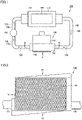
- FIG. 1 shows a configuration of an on-vehicle transformer according to a first embodiment.
- an on-vehicle transformer 100 according to the first embodiment includes a transformer main body 110, a tank 120, an insulating oil 130, a cooler 140, a connection pipe 150, and a pump 160.
- Transformer main body 110 is housed in tank 120. Insulating oil 130 is filled into tank 120 to cool transformer main body 110. Cooler 140 cools insulating oil 130. Connection pipe 150 connects tank 120 and cooler 140 to each other. Pump 160 is placed in connection pipe 150. Pump 160 circulates insulating oil 130 between tank 120 and cooler 140.
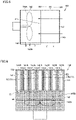
- Fig. 2 is a diagram of the cooler and a part of the connection pipe in the on-vehicle transformer in Fig. 1 , when viewed from an arrow II direction.
- Fig. 3 is a cross-sectional view of the cooler and a part of the connection pipe in the on-vehicle transformer in Fig. 1 , when viewed from a III-III line arrow direction.
- cooler 140 includes a heat exchange unit 141, an air intake unit 142 and an air intake filter 143.
- Air intake unit 142 is integrally connected to heat exchange unit 141.
- heat exchange unit 141 has a plurality of oil flow portions 141A and a plurality of air flow portions 141B.
- the plurality of oil flow portions 141A allow insulating oil 130 to flow in one direction.
- Heat exchange unit 141 is provided with an oil inflow header 141C and an oil outflow header 141D.
- Oil inflow header 141C is connected to one side of connection pipe 150.
- Oil inflow header 141C is provided at upstream ends of the plurality of oil flow portions 141A in the oil flow direction of insulating oil 130.
- Oil outflow header 141D is connected to the other side of connection pipe 150.
- Oil outflow header 141D is provided at downstream ends of the plurality of oil flow portions 141A in the oil flow direction of insulating oil 130.
- Fig. 4 is a diagram of the cooler in Fig. 2 , when viewed from an arrow IV direction.
- Fig. 5 is a diagram of the cooler in Fig. 2 , when viewed from an arrow V direction.
- Fig. 6 is a diagram of the cooler in Fig. 2 , when viewed from an arrow VI direction. Oil inflow header 141C and oil outflow header 141D are not shown in Figs. 4 to 6 .
- each of the plurality of air flow portions 141B is located between two of the plurality of oil flow portions 141A adjacent to each of the plurality of air flow portions 141B.
- a cooling fin 141F is provided in each of the plurality of air flow portions 141B in order to enhance the heat exchange efficiency.
- Each of the plurality of air flow portions 141B allows outdoor air to flow toward an interior of air intake unit 142 in a direction that crosses the oil flow direction of insulating oil 130 in the plurality of oil flow portions 141A.
- insulating oil 130 flows through each of a plurality of oil flow holes partitioned by cooling fin 141F.
- the oil flow direction of insulating oil 130 and the above-described air flow direction of the outdoor air are orthogonal to each other, when viewed from a direction of alignment of the plurality of oil flow portions 141A.
- Air intake unit 142 has an air intake fan 142A. Air intake fan 142A is located in air intake unit 142.
- Air intake fan 142A suctions the outdoor air into air intake unit 142 through air flow portions 141B.
- the outdoor air suctioned into air intake unit 142 by air intake fan 142A is discharged through an air discharge port 142B.
- air discharge port 142B is located on one side of air intake unit 142 in the oil flow direction of insulating oil 130.
- air intake filter 143 is located on the side of heat exchange unit 141 opposite to the air intake unit 142 side. Air intake filter 143 is configured to allow the outdoor air to flow therethrough, and is provided to cover the air-intake-side edges in the air flow direction in the plurality of air flow portions 141B. Air intake filter 143 is configured to be removable from air intake unit 142.
- Cooler 140 further includes an air discharge filter 144.
- Air discharge filter 144 has, for example, a grid-like outer shape. Air discharge filter 144 is configured to allow the outdoor air to flow therethrough, and is provided to cover air discharge port 142B. Air discharge filter 144 can suppress contact of rotating air intake fan 142A with a foreign object. Air discharge filter 144 is configured to be removable from air intake unit 142.
- a sliding mechanism 170 is provided between each of the plurality of oil flow portions 141A and a corresponding one of the plurality of air flow portions 141B adjacent to each of the plurality of oil flow portions 141A.
- Fig. 7 shows a state in which the plurality of air flow portions have been moved by the sliding mechanisms in the on-vehicle transformer according to the first embodiment.
- cooler 140 is shown from the same direction as that in Fig. 4 , and oil inflow header 141C and oil outflow header 141D are not shown.
- sliding mechanism 170 is configured to allow each of the plurality of air flow portions 141B to slide in a direction along the air flow direction of the outdoor air in the plurality of air flow portions 141B.
- air intake filter 143 is removed.
- sliding mechanism 170 has a sliding contact portion 171 and a rail portion 172.
- Sliding contact portion 171 is provided on each of the plurality of oil flow portions 141A.
- a plurality of sliding contact portions 171 are provided as sliding contact portions 171 for each of the plurality of oil flow portions 141A.
- sliding contact portion 171 has a rail shape extending in the above-described air flow direction in the present embodiment, sliding contact portion 171 may be formed of a plurality of rotatable rollers.
- sliding contact portion 171 is also in sliding contact with air flow portion 141B adjacent to oil flow portion 141A of the plurality of oil flow portions 141A provided with sliding contact portion 171.
- the efficiency of heat exchange between the plurality of air flow portions 141B and the plurality of oil flow portions 141A can be enhanced.
- Rail portion 172 is provided on each of the plurality of air flow portions 141B so as to be in sliding contact with sliding contact portion 171 directly or indirectly. Rail portion 172 extends in the direction along the above-described air flow direction.
- a not-shown grease is provided between rail portion 172 and sliding contact portion 171.
- rail portion 172 can smoothly slide with respect to sliding contact portion 171, and the efficiency of heat exchange between the plurality of air flow portions 141B and the plurality of oil flow portions 141A can be enhanced.
- Rail portion 172 may also be in sliding contact with oil flow portion 141A adjacent to air flow portion 141B of the plurality of air flow portions 141B provided with rail portion 172. As a result, the efficiency of heat exchange between the plurality of air flow portions 141B and the plurality of oil flow portions 141A can be enhanced.
- each of the plurality of air flow portions 141B can move such that in the above-described air flow direction, an edge E1 of each of the plurality of air flow portions 141B on the air intake unit 142 side is located, toward an opposite side of the air intake unit 142 side, at a distance from an edge E3 of each of the plurality of oil flow portions 141A on the opposite side of the air intake unit 142 side.
- each of the plurality of air flow portions 141B can be easily housed between two of the plurality of oil flow portions 141A adjacent to each of the plurality of air flow portions 141B by sliding mechanism 170. Therefore, the interior of the plurality of air flow portions 141B in cooler 140 can be efficiently cleaned. Furthermore, it is unnecessary to clean each of the plurality of air flow portions 141B from the inside of air intake unit 142, which can lead to a reduction in internal volume of air intake unit 142 and a reduction in size of air intake unit 142.
- sliding mechanism 170 has sliding contact portion 171 and rail portion 172.
- Sliding contact portion 171 is provided on each of the plurality of oil flow portions 141A.
- Rail portion 172 is provided on each of the plurality of air flow portions 141B so as to be in sliding contact with sliding contact portion 171 directly or indirectly.
- Rail portion 172 extends in the direction along the above-described air flow direction.
- cooler 140 further includes air intake filter 143 located on the side of heat exchange unit 141 opposite to the air intake unit 142 side.
- air intake filter 143 located on the side of heat exchange unit 141 opposite to the air intake unit 142 side.
- on-vehicle transformer according to a second embodiment will be described below.
- the on-vehicle transformer according to the second embodiment is different in configuration of the sliding mechanisms from on-vehicle transformer 100 according to the first embodiment. Therefore, description of features similar to those of on-vehicle transformer 100 according to the first embodiment will not be repeated.
- Fig. 8 is a cross-sectional view showing a part of a cooler in the on-vehicle transformer according to the second embodiment.
- Fig. 9 shows a state in which a plurality of air flow portions have been moved by sliding mechanisms in the on-vehicle transformer according to the second embodiment.
- a part of the cooler is shown in the same cross-sectional view as that of cooler 140 in the first embodiment shown in Fig. 3 , and only one of the plurality of air flow portions 141B is shown, and only oil flow portions 141A of the plurality of oil flow portions 141A adjacent to above-described one air flow portion 141B are shown.
- the state is shown from the same direction as the direction of illustration of cooler 140 in the first embodiment shown in Fig. 7 .
- a sliding mechanism 270 further has an intermediate rail portion 273.
- Intermediate rail portion 273 is provided between sliding contact portion 171 and rail portion 172.
- Intermediate rail portion 273 is slidable with respect to each of sliding contact portion 171 and rail portion 172.
- Intermediate rail portion 273 extends in the direction along the above-described air flow direction.
- edge E1 of each of the plurality of air flow portions 141B on the air intake unit 142 side is spaced, toward the opposite side of the air intake unit 142 side, apart from edge E3 of each of the plurality of oil flow portions 141A on the opposite side of the air intake unit 142 side.
- edge E1 of each of the plurality of air flow portions 141B on the air intake unit 142 side is spaced, toward the opposite side of the air intake unit 142 side, apart from edge E3 of each of the plurality of oil flow portions 141A on the opposite side of the air intake unit 142 side.
- a grease should also be provided between sliding contact portion 171 and intermediate rail portion 273 and between rail portion 172 and intermediate rail portion 273.
- the on-vehicle transformer according to the third embodiment is different from on-vehicle transformer 100 according to the first embodiment in that a cooler further includes a pressing unit. Therefore, description of features similar to those of on-vehicle transformer 100 according to the first embodiment will not be repeated.
- Fig. 10 shows a part of a cooler in the on-vehicle transformer according to the third embodiment.
- a part of the cooler is shown from the same direction as the direction of illustration of cooler 140 in the first embodiment shown in Fig. 4 .
- cooler 140 further includes a pressing unit 345.
- Pressing unit 345 presses heat exchange unit 141 from outside. Pressing unit 345 engages with heat exchange unit 141 to press heat exchange unit 141 from both sides in a direction of alignment of the plurality of oil flow portions 141A in heat exchange unit 141.
- the plurality of air flow portions 141B and the plurality of oil flow portions 141A can be brought into closer contact with each other, with sliding mechanisms 170 being interposed.
- the heat exchange efficiency in heat exchange unit 141 can be enhanced.
- pressing unit 345 has a pair of pressing portions 345A, a coupling member 345B and a support portion 345C.
- Each of the pair of pressing portions 345A is located outside a corresponding one of both ends of heat exchange unit 141 in the direction of alignment of the plurality of oil flow portions 141A.
- Each of the pair of pressing portions 345A is pressed against and coupled to a corresponding one of both ends of heat exchange unit 141 by coupling member 345B.
- Each of the pair of pressing portions 345A is coupled to a corresponding one of both ends of heat exchange unit 141 such that coupling can be released.
- a specific member of coupling member 345B is not particularly limited, examples of coupling member 345B include a bolt and the like.
- support portion 345C is connected to each of the pair of pressing portions 345A.
- pressing unit 345 is configured to be removable from heat exchange unit 141.
- Support portion 345C is located so as not to cover the whole of each of the plurality of air flow portions 141B.
- the on-vehicle transformer according to the fourth embodiment is different from on-vehicle transformer 100 according to the first embodiment in that a heat exchange unit is provided with a handle portion. Therefore, description of features similar to those of on-vehicle transformer 100 according to the first embodiment will not be repeated.
- Fig. 11 shows a state in which a plurality of air flow portions have been moved by sliding mechanisms in the on-vehicle transformer according to the fourth embodiment.
- the state is shown from the same direction as the direction of illustration of cooler 140 according to the first embodiment shown in Fig. 7 .
- a handle portion 441G is connected to an edge of each of the plurality of air flow portions 141B on an opposite side of the air intake unit 142 side.
- Handle portion 441G connects the plurality of air flow portions 141B to each other. Therefore, by pulling out handle portion 441G to the opposite side of the air intake unit 142 side, the plurality of air flow portions 141B can be slid at a time. Thus, the work efficiency of cleaning of the interior of the plurality of air flow portions 141B can be enhanced.
- Handle portion 441G is located so as not to cover the whole of each of the plurality of air flow portions 141B.
- handle portion 441G has a bar-like outer shape extending along a direction of alignment of the plurality of air flow portions 141B in the present embodiment, the outer shape of handle portion 441G is not particularly limited.
- Handle portion 441G may have a frame-like outer shape that covers a part of cooler 140.
- 100 on-vehicle transformer 110 transformer main body; 120 tank; 130 insulating oil; 140 cooler; 141 heat exchange unit; 141A oil flow portion; 141B air flow portion; 141C oil inflow header; 141D oil outflow header; 141F cooling fin; 142 air intake unit; 142A air intake fan; 142B air discharge port; 143 air intake filter; 144 air discharge filter; 150 connection pipe; 160 pump; 170, 270 sliding mechanism; 171 sliding contact portion; 172 rail portion; 273 intermediate rail portion; 345 pressing unit; 345A pressing portion; 345B coupling member; 345C support portion; 441G handle portion.
Landscapes
- Engineering & Computer Science (AREA)
- Mechanical Engineering (AREA)
- General Engineering & Computer Science (AREA)
- Physics & Mathematics (AREA)
- Thermal Sciences (AREA)
- Power Engineering (AREA)
- Chemical & Material Sciences (AREA)
- Combustion & Propulsion (AREA)
- Transformer Cooling (AREA)
Abstract
Description
- The present disclosure relates to an on-vehicle transformer.
-
Japanese Patent Laying-Open No. S54-47153 - PTL 1:
Japanese Patent Laying-Open No. S54-47153 - In order to cool an insulating oil, a cooler having air flow portions through which the suctioned outdoor air can flow is also used in a conventional on-vehicle transformer. As for the cooler used in the on-vehicle transformer, when the on-vehicle transformer is continuously used, dust accumulates in the air flow portions. This leads to a decrease in cooling performance and an increase in temperature of the insulating oil cooled by the cooler.
- Therefore, in the on-vehicle transformer, it is necessary to clean the dust by, for example, blowing air onto the dust accumulated in the air flow portions. In this case, it is conceivable to perform cleaning of the interior of the air flow portions from the edge side of the air flow portions through which the outdoor air flows in. However, when the air is blown from the above-described edge side, an air blowing direction is a forward direction with respect to an air flow direction in the air flow portions during the use of the cooler. Therefore, the accumulated dust cannot be sufficiently cleaned. In addition, it is also conceivable to perform cleaning of the interior of the air flow portions from the side of the air flow portions opposite to the edge side through which the outdoor air flows in. However, on the side opposite to the above-described edge side, an air intake fan is located near the air flow portions, and thus, the cleaning work is not easy, which leads to a decrease in efficiency of the cleaning work.
- Thus, it is conceivable to configure the air flow portions to be completely removable from the cooler as in the cooler described in PTL 1. However, the cooler used in the on-vehicle transformer is comparatively large in size, and thus, it is not easy to put the air flow portions completely removed from the cooler back into the cooler. When such cooler is used in the on-vehicle transformer, the efficiency of the above-described cleaning work rather decreases.
- The present disclosure has been made in light of the above-described problems, and an object of the present disclosure is to provide an on-vehicle transformer including a cooler in which the interior of air flow portions can be efficiently cleaned.
- An on-vehicle transformer based on the present disclosure includes: a transformer main body; a tank; an insulating oil; a cooler; a connection pipe; and a pump. The tank houses the transformer main body. The insulating oil is filled into the tank to cool the transformer main body. The cooler cools the insulating oil. The connection pipe connects the tank and the cooler to each other. The pump is placed in the connection pipe. The pump circulates the insulating oil between the tank and the cooler. The cooler includes a heat exchange unit and an air intake unit. The air intake unit is integrally connected to the heat exchange unit. The heat exchange unit has a plurality of oil flow portions and a plurality of air flow portions. The plurality of oil flow portions allow the insulating oil to flow in one direction. Each of the plurality of air flow portions is located between two of the plurality of oil flow portions adj acent to each of the plurality of air flow portions. Each of the plurality of air flow portions allows outdoor air to flow toward an interior of the air intake unit in a direction that crosses an oil flow direction of the insulating oil in the plurality of oil flow portions. The air intake unit has an air intake fan. The air intake fan is located in the air intake unit. The air intake fan suctions the outdoor air into the air intake unit through the air flow portions. A sliding mechanism is provided between each of the plurality of oil flow portions and a corresponding one of the plurality of air flow portions adjacent to each of the plurality of oil flow portions. The sliding mechanism is configured to allow each of the plurality of air flow portions to slide in a direction along an air flow direction of the outdoor air in the plurality of air flow portions. By sliding each of the plurality of air flow portions along the sliding mechanism, each of the plurality of air flow portions can move such that in the air flow direction, an edge of each of the plurality of air flow portions on an air intake unit side is located, toward an opposite side of the air intake unit side, at a distance from an edge of each of the plurality of oil flow portions on the opposite side of the air intake unit side.
- According to the present disclosure, at the time of cleaning of the interior of the plurality of air flow portions in the cooler, the cleaning can be performed from the edge side of each of the plurality of air flow portions on the air intake unit side, and thus, dust in the plurality of air flow portions can be easily removed. Furthermore, after the above-described cleaning, each of the plurality of air flow portions can be easily housed between two of the plurality of oil flow portions adjacent to each of the plurality of air flow portions by the sliding mechanism. Therefore, the interior of the plurality of air flow portions in the cooler can be efficiently cleaned.
-
-
Fig. 1 shows a configuration of an on-vehicle transformer according to a first embodiment. -
Fig. 2 is a diagram of a cooler and a part of a connection pipe in the on-vehicle transformer inFig. 1 , when viewed from an arrow II direction. -
Fig. 3 is a cross-sectional view of the cooler and a part of the connection pipe in the on-vehicle transformer inFig. 1 , when viewed from a III-III line arrow direction. -
Fig. 4 is a diagram of the cooler inFig. 2 , when viewed from an arrow IV direction. -
Fig. 5 is a diagram of the cooler inFig. 2 , when viewed from an arrow V direction. -
Fig. 6 is a diagram of the cooler inFig. 2 , when viewed from an arrow VI direction. -
Fig. 7 shows a state in which a plurality of air flow portions have been moved by sliding mechanisms in the on-vehicle transformer according to the first embodiment. -
Fig. 8 is a cross-sectional view showing a part of a cooler in an on-vehicle transformer according to a second embodiment. -
Fig. 9 shows a state in which a plurality of air flow portions have been moved by sliding mechanisms in the on-vehicle transformer according to the second embodiment. -
Fig. 10 shows a part of a cooler in an on-vehicle transformer according to a third embodiment. -
Fig. 11 shows a state in which a plurality of air flow portions have been moved by sliding mechanisms in an on-vehicle transformer according to a fourth embodiment. - An on-vehicle transformer according to each embodiment will be described hereinafter with reference to the drawings. In the embodiments described below, the same or corresponding portions in the drawings are denoted by the same reference characters and description thereof will not be repeated.
-
Fig. 1 shows a configuration of an on-vehicle transformer according to a first embodiment. As shown inFig. 1 , an on-vehicle transformer 100 according to the first embodiment includes a transformermain body 110, atank 120, an insulatingoil 130, a cooler 140, aconnection pipe 150, and apump 160. - Transformer
main body 110 is housed intank 120. Insulatingoil 130 is filled intotank 120 to cool transformermain body 110.Cooler 140 cools insulatingoil 130.Connection pipe 150 connectstank 120 and cooler 140 to each other.Pump 160 is placed inconnection pipe 150.Pump 160 circulates insulatingoil 130 betweentank 120 and cooler 140. -
Fig. 2 is a diagram of the cooler and a part of the connection pipe in the on-vehicle transformer inFig. 1 , when viewed from an arrow II direction.Fig. 3 is a cross-sectional view of the cooler and a part of the connection pipe in the on-vehicle transformer inFig. 1 , when viewed from a III-III line arrow direction. - As shown in
Figs. 1 to 3 , cooler 140 includes aheat exchange unit 141, anair intake unit 142 and anair intake filter 143.Air intake unit 142 is integrally connected to heatexchange unit 141. - As shown in
Fig. 3 ,heat exchange unit 141 has a plurality ofoil flow portions 141A and a plurality ofair flow portions 141B. The plurality ofoil flow portions 141A allow insulatingoil 130 to flow in one direction. -
Heat exchange unit 141 is provided with anoil inflow header 141C and anoil outflow header 141D.Oil inflow header 141C is connected to one side ofconnection pipe 150.Oil inflow header 141C is provided at upstream ends of the plurality ofoil flow portions 141A in the oil flow direction of insulatingoil 130.Oil outflow header 141D is connected to the other side ofconnection pipe 150.Oil outflow header 141D is provided at downstream ends of the plurality ofoil flow portions 141A in the oil flow direction of insulatingoil 130. -
Fig. 4 is a diagram of the cooler inFig. 2 , when viewed from an arrow IV direction.Fig. 5 is a diagram of the cooler inFig. 2 , when viewed from an arrow V direction.Fig. 6 is a diagram of the cooler inFig. 2 , when viewed from an arrow VI direction.Oil inflow header 141C andoil outflow header 141D are not shown inFigs. 4 to 6 . - As shown in
Figs. 3 to 6 , each of the plurality ofair flow portions 141B is located between two of the plurality ofoil flow portions 141A adjacent to each of the plurality ofair flow portions 141B. A coolingfin 141F is provided in each of the plurality ofair flow portions 141B in order to enhance the heat exchange efficiency. - Each of the plurality of
air flow portions 141B allows outdoor air to flow toward an interior ofair intake unit 142 in a direction that crosses the oil flow direction of insulatingoil 130 in the plurality ofoil flow portions 141A. In the present embodiment, in each of the plurality ofair flow portions 141B, insulatingoil 130 flows through each of a plurality of oil flow holes partitioned by coolingfin 141F. Specifically, the oil flow direction of insulatingoil 130 and the above-described air flow direction of the outdoor air are orthogonal to each other, when viewed from a direction of alignment of the plurality ofoil flow portions 141A. -
Air intake unit 142 has anair intake fan 142A.Air intake fan 142A is located inair intake unit 142. -
Air intake fan 142A suctions the outdoor air intoair intake unit 142 throughair flow portions 141B. The outdoor air suctioned intoair intake unit 142 byair intake fan 142A is discharged through anair discharge port 142B. In the present embodiment,air discharge port 142B is located on one side ofair intake unit 142 in the oil flow direction of insulatingoil 130. - In the present embodiment,
air intake filter 143 is located on the side ofheat exchange unit 141 opposite to theair intake unit 142 side.Air intake filter 143 is configured to allow the outdoor air to flow therethrough, and is provided to cover the air-intake-side edges in the air flow direction in the plurality ofair flow portions 141B.Air intake filter 143 is configured to be removable fromair intake unit 142. -
Cooler 140 further includes anair discharge filter 144.Air discharge filter 144 has, for example, a grid-like outer shape.Air discharge filter 144 is configured to allow the outdoor air to flow therethrough, and is provided to coverair discharge port 142B.Air discharge filter 144 can suppress contact of rotatingair intake fan 142A with a foreign object.Air discharge filter 144 is configured to be removable fromair intake unit 142. - As shown in
Figs. 3 to 6 , a slidingmechanism 170 is provided between each of the plurality ofoil flow portions 141A and a corresponding one of the plurality ofair flow portions 141B adjacent to each of the plurality ofoil flow portions 141A. -
Fig. 7 shows a state in which the plurality of air flow portions have been moved by the sliding mechanisms in the on-vehicle transformer according to the first embodiment. InFig. 7 , cooler 140 is shown from the same direction as that inFig. 4 , andoil inflow header 141C andoil outflow header 141D are not shown. - As shown in
Figs. 3, 4 and7 , slidingmechanism 170 is configured to allow each of the plurality ofair flow portions 141B to slide in a direction along the air flow direction of the outdoor air in the plurality ofair flow portions 141B. When the plurality ofair flow portions 141B are slid,air intake filter 143 is removed. - In the present embodiment, sliding
mechanism 170 has a slidingcontact portion 171 and arail portion 172. Slidingcontact portion 171 is provided on each of the plurality ofoil flow portions 141A. In the present embodiment, a plurality of slidingcontact portions 171 are provided as slidingcontact portions 171 for each of the plurality ofoil flow portions 141A. Although slidingcontact portion 171 has a rail shape extending in the above-described air flow direction in the present embodiment, slidingcontact portion 171 may be formed of a plurality of rotatable rollers. - In addition, in the present embodiment, sliding
contact portion 171 is also in sliding contact withair flow portion 141B adjacent tooil flow portion 141A of the plurality ofoil flow portions 141A provided with slidingcontact portion 171. As a result, the efficiency of heat exchange between the plurality ofair flow portions 141B and the plurality ofoil flow portions 141A can be enhanced. -
Rail portion 172 is provided on each of the plurality ofair flow portions 141B so as to be in sliding contact with slidingcontact portion 171 directly or indirectly.Rail portion 172 extends in the direction along the above-described air flow direction. - In the present embodiment, a not-shown grease is provided between
rail portion 172 and slidingcontact portion 171. Thus,rail portion 172 can smoothly slide with respect to slidingcontact portion 171, and the efficiency of heat exchange between the plurality ofair flow portions 141B and the plurality ofoil flow portions 141A can be enhanced.Rail portion 172 may also be in sliding contact withoil flow portion 141A adjacent toair flow portion 141B of the plurality ofair flow portions 141B provided withrail portion 172. As a result, the efficiency of heat exchange between the plurality ofair flow portions 141B and the plurality ofoil flow portions 141A can be enhanced. - As shown in
Figs. 4 and7 , in on-vehicle transformer 100 according to the first embodiment, by sliding each of the plurality ofair flow portions 141B along slidingmechanism 170, each of the plurality ofair flow portions 141B can move such that in the above-described air flow direction, an edge E1 of each of the plurality ofair flow portions 141B on theair intake unit 142 side is located, toward an opposite side of theair intake unit 142 side, at a distance from an edge E3 of each of the plurality ofoil flow portions 141A on the opposite side of theair intake unit 142 side. - Therefore, at the time of cleaning of the interior of the plurality of
air flow portions 141B in cooler 140, the cleaning can be performed from the edge E1 side of each of the plurality ofair flow portions 141B on theair intake unit 142 side, and thus, dust in the plurality ofair flow portions 141B can be easily removed. Furthermore, after the above-described cleaning, each of the plurality ofair flow portions 141B can be easily housed between two of the plurality ofoil flow portions 141A adjacent to each of the plurality ofair flow portions 141B by slidingmechanism 170. Therefore, the interior of the plurality ofair flow portions 141B in cooler 140 can be efficiently cleaned. Furthermore, it is unnecessary to clean each of the plurality ofair flow portions 141B from the inside ofair intake unit 142, which can lead to a reduction in internal volume ofair intake unit 142 and a reduction in size ofair intake unit 142. - In addition, in the first embodiment, sliding
mechanism 170 has slidingcontact portion 171 andrail portion 172. Slidingcontact portion 171 is provided on each of the plurality ofoil flow portions 141A.Rail portion 172 is provided on each of the plurality ofair flow portions 141B so as to be in sliding contact with slidingcontact portion 171 directly or indirectly.Rail portion 172 extends in the direction along the above-described air flow direction. Thus, slidingmechanism 170 can be provided in a simple configuration. - In addition, in the first embodiment, cooler 140 further includes
air intake filter 143 located on the side ofheat exchange unit 141 opposite to theair intake unit 142 side. Thus, accumulation of dust inair flow portions 141B can be suppressed. - An on-vehicle transformer according to a second embodiment will be described below. The on-vehicle transformer according to the second embodiment is different in configuration of the sliding mechanisms from on-
vehicle transformer 100 according to the first embodiment. Therefore, description of features similar to those of on-vehicle transformer 100 according to the first embodiment will not be repeated. -
Fig. 8 is a cross-sectional view showing a part of a cooler in the on-vehicle transformer according to the second embodiment.Fig. 9 shows a state in which a plurality of air flow portions have been moved by sliding mechanisms in the on-vehicle transformer according to the second embodiment. InFig. 8 , a part of the cooler is shown in the same cross-sectional view as that of cooler 140 in the first embodiment shown inFig. 3 , and only one of the plurality ofair flow portions 141B is shown, and onlyoil flow portions 141A of the plurality ofoil flow portions 141A adjacent to above-described oneair flow portion 141B are shown. InFig. 9 , the state is shown from the same direction as the direction of illustration of cooler 140 in the first embodiment shown inFig. 7 . - As shown in
Figs. 8 and9 , in the second embodiment, a slidingmechanism 270 further has anintermediate rail portion 273.Intermediate rail portion 273 is provided between slidingcontact portion 171 andrail portion 172.Intermediate rail portion 273 is slidable with respect to each of slidingcontact portion 171 andrail portion 172.Intermediate rail portion 273 extends in the direction along the above-described air flow direction. - The above-described configuration makes it possible to increase a spacing distance when in the above-described air flow direction, edge E1 of each of the plurality of
air flow portions 141B on theair intake unit 142 side is spaced, toward the opposite side of theair intake unit 142 side, apart from edge E3 of each of the plurality ofoil flow portions 141A on the opposite side of theair intake unit 142 side. Thus, the interior ofair flow portions 141B can be cleaned more easily. - It is preferable that a grease should also be provided between sliding
contact portion 171 andintermediate rail portion 273 and betweenrail portion 172 andintermediate rail portion 273. - An on-vehicle transformer according to a third embodiment will be described below. The on-vehicle transformer according to the third embodiment is different from on-
vehicle transformer 100 according to the first embodiment in that a cooler further includes a pressing unit. Therefore, description of features similar to those of on-vehicle transformer 100 according to the first embodiment will not be repeated. -
Fig. 10 shows a part of a cooler in the on-vehicle transformer according to the third embodiment. InFig. 10 , a part of the cooler is shown from the same direction as the direction of illustration of cooler 140 in the first embodiment shown inFig. 4 . - As shown in
Fig. 10 , in the third embodiment, cooler 140 further includes apressing unit 345.Pressing unit 345 pressesheat exchange unit 141 from outside.Pressing unit 345 engages withheat exchange unit 141 to pressheat exchange unit 141 from both sides in a direction of alignment of the plurality ofoil flow portions 141A inheat exchange unit 141. - Therefore, the plurality of
air flow portions 141B and the plurality ofoil flow portions 141A can be brought into closer contact with each other, with slidingmechanisms 170 being interposed. Thus, the heat exchange efficiency inheat exchange unit 141 can be enhanced. - In the present embodiment, pressing
unit 345 has a pair ofpressing portions 345A, acoupling member 345B and asupport portion 345C. Each of the pair ofpressing portions 345A is located outside a corresponding one of both ends ofheat exchange unit 141 in the direction of alignment of the plurality ofoil flow portions 141A. Each of the pair ofpressing portions 345A is pressed against and coupled to a corresponding one of both ends ofheat exchange unit 141 by couplingmember 345B. Each of the pair ofpressing portions 345A is coupled to a corresponding one of both ends ofheat exchange unit 141 such that coupling can be released. Although a specific member ofcoupling member 345B is not particularly limited, examples ofcoupling member 345B include a bolt and the like. In the present embodiment,support portion 345C is connected to each of the pair ofpressing portions 345A. As described above, pressingunit 345 is configured to be removable fromheat exchange unit 141. Thus, when pressingunit 345 is removed, the plurality ofair flow portions 141B can be slid and moved.Support portion 345C is located so as not to cover the whole of each of the plurality ofair flow portions 141B. - An on-vehicle transformer according to a fourth embodiment will be described below. The on-vehicle transformer according to the fourth embodiment is different from on-
vehicle transformer 100 according to the first embodiment in that a heat exchange unit is provided with a handle portion. Therefore, description of features similar to those of on-vehicle transformer 100 according to the first embodiment will not be repeated. -
Fig. 11 shows a state in which a plurality of air flow portions have been moved by sliding mechanisms in the on-vehicle transformer according to the fourth embodiment. InFig. 11 , the state is shown from the same direction as the direction of illustration of cooler 140 according to the first embodiment shown inFig. 7 . - As shown in
Fig. 11 , in the fourth embodiment, ahandle portion 441G is connected to an edge of each of the plurality ofair flow portions 141B on an opposite side of theair intake unit 142 side.Handle portion 441G connects the plurality ofair flow portions 141B to each other. Therefore, by pulling outhandle portion 441G to the opposite side of theair intake unit 142 side, the plurality ofair flow portions 141B can be slid at a time. Thus, the work efficiency of cleaning of the interior of the plurality ofair flow portions 141B can be enhanced. -
Handle portion 441G is located so as not to cover the whole of each of the plurality ofair flow portions 141B. In addition, althoughhandle portion 441G has a bar-like outer shape extending along a direction of alignment of the plurality ofair flow portions 141B in the present embodiment, the outer shape ofhandle portion 441G is not particularly limited.Handle portion 441G may have a frame-like outer shape that covers a part of cooler 140. - In the description of the embodiments above, the combinable features may be combined with each other.
- It is noted that the embodiments disclosed herein are illustrative in every respect, and do not form a basis for restrictive interpretation. Therefore, the technical scope of the present disclosure should not be interpreted based on the foregoing embodiments only, but is defined by the terms of the claims. Further, any modifications within the meaning and scope equivalent to the terms of the claims are encompassed.
- 100 on-vehicle transformer; 110 transformer main body; 120 tank; 130 insulating oil; 140 cooler; 141 heat exchange unit; 141A oil flow portion; 141B air flow portion; 141C oil inflow header; 141D oil outflow header; 141F cooling fin; 142 air intake unit; 142A air intake fan; 142B air discharge port; 143 air intake filter; 144 air discharge filter; 150 connection pipe; 160 pump; 170, 270 sliding mechanism; 171 sliding contact portion; 172 rail portion; 273 intermediate rail portion; 345 pressing unit; 345A pressing portion; 345B coupling member; 345C support portion; 441G handle portion.
Claims (5)
- An on-vehicle transformer comprising:a transformer main body;a tank that houses the transformer main body;an insulating oil filled into the tank to cool the transformer main body;a cooler that cools the insulating oil;a connection pipe that connects the tank and the cooler to each other; anda pump placed in the connection pipe to circulate the insulating oil between the tank and the cooler, whereinthe cooler includes a heat exchange unit, and an air intake unit integrally connected to the heat exchange unit,the heat exchange unit has a plurality of oil flow portions and a plurality of air flow portions, the plurality of oil flow portions allowing the insulating oil to flow in one direction, each of the plurality of air flow portions being located between two of the plurality of oil flow portions adjacent to each of the plurality of air flow portions to allow outdoor air to flow toward an interior of the air intake unit in a direction that crosses an oil flow direction of the insulating oil in the plurality of oil flow portions,the air intake unit has an air intake fan located in the air intake unit to suction the outdoor air into the air intake unit through the air flow portions,a sliding mechanism is provided between each of the plurality of oil flow portions and a corresponding one of the plurality of air flow portions adjacent to each of the plurality of oil flow portions, the sliding mechanism being configured to allow each of the plurality of air flow portions to slide in a direction along an air flow direction of the outdoor air in the plurality of air flow portions, andby sliding each of the plurality of air flow portions along the sliding mechanism, each of the plurality of air flow portions can move such that in the air flow direction, an edge of each of the plurality of air flow portions on an air intake unit side is located, toward an opposite side of the air intake unit side, at a distance from an edge of each of the plurality of oil flow portions on the opposite side of the air intake unit side.
- The on-vehicle transformer according to claim 1, wherein
the sliding mechanism has a sliding contact portion and a rail portion, the sliding contact portion being provided on each of the plurality of oil flow portions, the rail portion being provided on each of the plurality of air flow portions so as to be in sliding contact with the sliding contact portion directly or indirectly, and extending in the direction along the air flow direction. - The on-vehicle transformer according to claim 2, wherein
an intermediate rail portion is further provided between the sliding contact portion and the rail portion, the intermediate rail portion being slidable with respect to each of the sliding contact portion and the rail portion, and extending in the direction along the air flow direction. - The on-vehicle transformer according to any one of claims 1 to 3, whereinthe cooler further includes a pressing unit that presses the heat exchange unit from outside, andthe pressing unit engages with the heat exchange unit to press the heat exchange unit from both sides in a direction of alignment of the plurality of oil flow portions in the heat exchange unit.
- The on-vehicle transformer according to any one of claims 1 to 4, wherein
the cooler further includes an air intake filter located on a side of the heat exchange unit opposite to the air intake unit side.
Applications Claiming Priority (1)
| Application Number | Priority Date | Filing Date | Title |
|---|---|---|---|
| PCT/JP2020/000854 WO2021144837A1 (en) | 2020-01-14 | 2020-01-14 | Vehicle-mounted transformer |
Publications (3)
| Publication Number | Publication Date |
|---|---|
| EP4092370A1 true EP4092370A1 (en) | 2022-11-23 |
| EP4092370A4 EP4092370A4 (en) | 2023-02-08 |
| EP4092370B1 EP4092370B1 (en) | 2024-12-25 |
Family
ID=72829253
Family Applications (1)
| Application Number | Title | Priority Date | Filing Date |
|---|---|---|---|
| EP20914198.5A Active EP4092370B1 (en) | 2020-01-14 | 2020-01-14 | Vehicle-mounted transformer |
Country Status (3)
| Country | Link |
|---|---|
| EP (1) | EP4092370B1 (en) |
| JP (1) | JP6771701B1 (en) |
| WO (1) | WO2021144837A1 (en) |
Families Citing this family (3)
| Publication number | Priority date | Publication date | Assignee | Title |
|---|---|---|---|---|
| CN113205946B (en) * | 2021-05-04 | 2022-03-15 | 广东科源电气股份有限公司 | a power transformer |
| CN113363052B (en) * | 2021-06-07 | 2022-08-30 | 合肥市菲力克斯电子科技有限公司 | Protective device of energy-saving electronic transformer |
| CN113345678B (en) * | 2021-06-07 | 2022-11-22 | 合肥市菲力克斯电子科技有限公司 | Dustproof protection mechanism of electronic transformer |
Family Cites Families (8)
| Publication number | Priority date | Publication date | Assignee | Title |
|---|---|---|---|---|
| JPS5447153A (en) | 1977-09-21 | 1979-04-13 | Hitachi Ltd | Heat exchanger |
| JPS5810583U (en) * | 1981-07-13 | 1983-01-24 | 住友精密工業株式会社 | Heat exchanger |
| JPS5895361U (en) * | 1981-12-22 | 1983-06-28 | 株式会社東芝 | Vehicle electrical equipment cooling system |
| JPS59164890A (en) * | 1983-03-11 | 1984-09-18 | Iseki & Co Ltd | radiator |
| JP2549524B2 (en) * | 1987-07-15 | 1996-10-30 | 株式会社荏原シンワ | cooling tower |
| JPH0588619U (en) * | 1992-05-11 | 1993-12-03 | 株式会社中村自工 | Air-cooled oil cooler filter |
| JPH10267579A (en) * | 1997-03-21 | 1998-10-09 | Daikin Ind Ltd | Heat exchange element |
| EP3796343B1 (en) * | 2018-05-17 | 2025-06-04 | Mitsubishi Electric Corporation | On-vehicle transformer and oil flow relay |
-
2020
- 2020-01-14 JP JP2020523829A patent/JP6771701B1/en active Active
- 2020-01-14 WO PCT/JP2020/000854 patent/WO2021144837A1/en not_active Ceased
- 2020-01-14 EP EP20914198.5A patent/EP4092370B1/en active Active
Also Published As
| Publication number | Publication date |
|---|---|
| WO2021144837A1 (en) | 2021-07-22 |
| EP4092370A4 (en) | 2023-02-08 |
| JP6771701B1 (en) | 2020-10-21 |
| JPWO2021144837A1 (en) | 2021-07-22 |
| EP4092370B1 (en) | 2024-12-25 |
Similar Documents
| Publication | Publication Date | Title |
|---|---|---|
| EP4092370A1 (en) | Vehicle-mounted transformer | |
| US8619424B2 (en) | Electronic device | |
| US20140190673A1 (en) | Heat Exchanger, Particularly For A Motor Vehicle | |
| KR20140037351A (en) | Battery cooling apparatus for vehicle | |
| CN109617375B (en) | Diesel locomotive highly integrated cooling system | |
| EP2799306B1 (en) | Air conditioning device for vehicle | |
| JP2015031501A (en) | Heat exchanger fixing plate and air conditioner | |
| CN215343502U (en) | A water-cooled cooling power cabinet | |
| US20250189231A1 (en) | Cooling module | |
| CN111735116B (en) | Mobile air conditioner | |
| CN212482191U (en) | Flue gas heat exchanger for easy cleaning | |
| CN219876695U (en) | Novel heat abstractor of remote controller | |
| CN108534247A (en) | Package AC plant | |
| CN212619579U (en) | Electric pulse spark machine coolant liquid circulating filter device | |
| CN210624747U (en) | Constant temperature and humidity air conditioning unit | |
| CN115195452A (en) | Air cooling device | |
| CN115066141A (en) | Electromechanical device heat radiation structure | |
| CN204902069U (en) | Dehumidifier | |
| CN218654915U (en) | Self-cooling electromagnetic iron remover | |
| KR100579965B1 (en) | Air conditioner condenser | |
| CN217952850U (en) | Air guide type refrigeration assembly | |
| CN216698031U (en) | Ventilation cooling type lathe transformer | |
| CN223471391U (en) | LED display screen with good heat dissipation efficiency | |
| CN213273294U (en) | New energy automobile water-cooled condenser | |
| CN219028439U (en) | Cooling device for polypropylene production |
Legal Events
| Date | Code | Title | Description |
|---|---|---|---|
| STAA | Information on the status of an ep patent application or granted ep patent |
Free format text: STATUS: THE INTERNATIONAL PUBLICATION HAS BEEN MADE |
|
| PUAI | Public reference made under article 153(3) epc to a published international application that has entered the european phase |
Free format text: ORIGINAL CODE: 0009012 |
|
| STAA | Information on the status of an ep patent application or granted ep patent |
Free format text: STATUS: REQUEST FOR EXAMINATION WAS MADE |
|
| 17P | Request for examination filed |
Effective date: 20220504 |
|
| AK | Designated contracting states |
Kind code of ref document: A1 Designated state(s): AL AT BE BG CH CY CZ DE DK EE ES FI FR GB GR HR HU IE IS IT LI LT LU LV MC MK MT NL NO PL PT RO RS SE SI SK SM TR |
|
| A4 | Supplementary search report drawn up and despatched |
Effective date: 20230109 |
|
| RIC1 | Information provided on ipc code assigned before grant |
Ipc: F28G 1/16 19680901ALI20230102BHEP Ipc: F28F 9/02 19680901ALI20230102BHEP Ipc: F28F 19/01 19950101ALI20230102BHEP Ipc: F28D 21/00 19680901ALI20230102BHEP Ipc: H01F 27/12 19680901ALI20230102BHEP Ipc: F28F 3/08 19680901ALI20230102BHEP Ipc: F28D 1/06 19680901ALI20230102BHEP Ipc: F28D 1/053 19850101AFI20230102BHEP |
|
| DAV | Request for validation of the european patent (deleted) | ||
| DAX | Request for extension of the european patent (deleted) | ||
| GRAP | Despatch of communication of intention to grant a patent |
Free format text: ORIGINAL CODE: EPIDOSNIGR1 |
|
| STAA | Information on the status of an ep patent application or granted ep patent |
Free format text: STATUS: GRANT OF PATENT IS INTENDED |
|
| RIC1 | Information provided on ipc code assigned before grant |
Ipc: F28G 1/16 20060101ALI20240216BHEP Ipc: F28F 9/02 20060101ALI20240216BHEP Ipc: F28F 19/01 20060101ALI20240216BHEP Ipc: F28D 21/00 20060101ALI20240216BHEP Ipc: H01F 27/12 20060101ALI20240216BHEP Ipc: F28F 3/08 20060101ALI20240216BHEP Ipc: F28D 1/06 20060101ALI20240216BHEP Ipc: F28D 1/053 20060101AFI20240216BHEP |
|
| INTG | Intention to grant announced |
Effective date: 20240305 |
|
| GRAJ | Information related to disapproval of communication of intention to grant by the applicant or resumption of examination proceedings by the epo deleted |
Free format text: ORIGINAL CODE: EPIDOSDIGR1 |
|
| STAA | Information on the status of an ep patent application or granted ep patent |
Free format text: STATUS: REQUEST FOR EXAMINATION WAS MADE |
|
| GRAP | Despatch of communication of intention to grant a patent |
Free format text: ORIGINAL CODE: EPIDOSNIGR1 |
|
| STAA | Information on the status of an ep patent application or granted ep patent |
Free format text: STATUS: GRANT OF PATENT IS INTENDED |
|
| INTC | Intention to grant announced (deleted) | ||
| INTG | Intention to grant announced |
Effective date: 20240717 |
|
| GRAS | Grant fee paid |
Free format text: ORIGINAL CODE: EPIDOSNIGR3 |
|
| GRAA | (expected) grant |
Free format text: ORIGINAL CODE: 0009210 |
|
| STAA | Information on the status of an ep patent application or granted ep patent |
Free format text: STATUS: THE PATENT HAS BEEN GRANTED |
|
| AK | Designated contracting states |
Kind code of ref document: B1 Designated state(s): AL AT BE BG CH CY CZ DE DK EE ES FI FR GB GR HR HU IE IS IT LI LT LU LV MC MK MT NL NO PL PT RO RS SE SI SK SM TR |
|
| REG | Reference to a national code |
Ref country code: GB Ref legal event code: FG4D |
|
| REG | Reference to a national code |
Ref country code: CH Ref legal event code: EP |
|
| REG | Reference to a national code |
Ref country code: DE Ref legal event code: R096 Ref document number: 602020043858 Country of ref document: DE |
|
| REG | Reference to a national code |
Ref country code: IE Ref legal event code: FG4D |
|
| REG | Reference to a national code |
Ref country code: LT Ref legal event code: MG9D |
|
| PG25 | Lapsed in a contracting state [announced via postgrant information from national office to epo] |
Ref country code: HR Free format text: LAPSE BECAUSE OF FAILURE TO SUBMIT A TRANSLATION OF THE DESCRIPTION OR TO PAY THE FEE WITHIN THE PRESCRIBED TIME-LIMIT Effective date: 20241225 |
|
| PG25 | Lapsed in a contracting state [announced via postgrant information from national office to epo] |
Ref country code: FI Free format text: LAPSE BECAUSE OF FAILURE TO SUBMIT A TRANSLATION OF THE DESCRIPTION OR TO PAY THE FEE WITHIN THE PRESCRIBED TIME-LIMIT Effective date: 20241225 |
|
| PG25 | Lapsed in a contracting state [announced via postgrant information from national office to epo] |
Ref country code: BG Free format text: LAPSE BECAUSE OF FAILURE TO SUBMIT A TRANSLATION OF THE DESCRIPTION OR TO PAY THE FEE WITHIN THE PRESCRIBED TIME-LIMIT Effective date: 20241225 |
|
| PG25 | Lapsed in a contracting state [announced via postgrant information from national office to epo] |
Ref country code: NO Free format text: LAPSE BECAUSE OF FAILURE TO SUBMIT A TRANSLATION OF THE DESCRIPTION OR TO PAY THE FEE WITHIN THE PRESCRIBED TIME-LIMIT Effective date: 20250325 |
|
| PG25 | Lapsed in a contracting state [announced via postgrant information from national office to epo] |
Ref country code: LV Free format text: LAPSE BECAUSE OF FAILURE TO SUBMIT A TRANSLATION OF THE DESCRIPTION OR TO PAY THE FEE WITHIN THE PRESCRIBED TIME-LIMIT Effective date: 20241225 Ref country code: GR Free format text: LAPSE BECAUSE OF FAILURE TO SUBMIT A TRANSLATION OF THE DESCRIPTION OR TO PAY THE FEE WITHIN THE PRESCRIBED TIME-LIMIT Effective date: 20250326 |
|
| PG25 | Lapsed in a contracting state [announced via postgrant information from national office to epo] |
Ref country code: RS Free format text: LAPSE BECAUSE OF FAILURE TO SUBMIT A TRANSLATION OF THE DESCRIPTION OR TO PAY THE FEE WITHIN THE PRESCRIBED TIME-LIMIT Effective date: 20250325 |
|
| REG | Reference to a national code |
Ref country code: NL Ref legal event code: MP Effective date: 20241225 |
|
| PG25 | Lapsed in a contracting state [announced via postgrant information from national office to epo] |
Ref country code: NL Free format text: LAPSE BECAUSE OF FAILURE TO SUBMIT A TRANSLATION OF THE DESCRIPTION OR TO PAY THE FEE WITHIN THE PRESCRIBED TIME-LIMIT Effective date: 20241225 |
|
| REG | Reference to a national code |
Ref country code: AT Ref legal event code: MK05 Ref document number: 1754468 Country of ref document: AT Kind code of ref document: T Effective date: 20241225 |
|
| PG25 | Lapsed in a contracting state [announced via postgrant information from national office to epo] |
Ref country code: SM Free format text: LAPSE BECAUSE OF FAILURE TO SUBMIT A TRANSLATION OF THE DESCRIPTION OR TO PAY THE FEE WITHIN THE PRESCRIBED TIME-LIMIT Effective date: 20241225 |
|
| PG25 | Lapsed in a contracting state [announced via postgrant information from national office to epo] |
Ref country code: PL Free format text: LAPSE BECAUSE OF FAILURE TO SUBMIT A TRANSLATION OF THE DESCRIPTION OR TO PAY THE FEE WITHIN THE PRESCRIBED TIME-LIMIT Effective date: 20241225 |
|
| PG25 | Lapsed in a contracting state [announced via postgrant information from national office to epo] |
Ref country code: ES Free format text: LAPSE BECAUSE OF FAILURE TO SUBMIT A TRANSLATION OF THE DESCRIPTION OR TO PAY THE FEE WITHIN THE PRESCRIBED TIME-LIMIT Effective date: 20241225 |
|
| PG25 | Lapsed in a contracting state [announced via postgrant information from national office to epo] |
Ref country code: IS Free format text: LAPSE BECAUSE OF FAILURE TO SUBMIT A TRANSLATION OF THE DESCRIPTION OR TO PAY THE FEE WITHIN THE PRESCRIBED TIME-LIMIT Effective date: 20250425 |
|
| PG25 | Lapsed in a contracting state [announced via postgrant information from national office to epo] |
Ref country code: PT Free format text: LAPSE BECAUSE OF FAILURE TO SUBMIT A TRANSLATION OF THE DESCRIPTION OR TO PAY THE FEE WITHIN THE PRESCRIBED TIME-LIMIT Effective date: 20250428 |
|
| PG25 | Lapsed in a contracting state [announced via postgrant information from national office to epo] |
Ref country code: EE Free format text: LAPSE BECAUSE OF FAILURE TO SUBMIT A TRANSLATION OF THE DESCRIPTION OR TO PAY THE FEE WITHIN THE PRESCRIBED TIME-LIMIT Effective date: 20241225 |
|
| PG25 | Lapsed in a contracting state [announced via postgrant information from national office to epo] |
Ref country code: RO Free format text: LAPSE BECAUSE OF FAILURE TO SUBMIT A TRANSLATION OF THE DESCRIPTION OR TO PAY THE FEE WITHIN THE PRESCRIBED TIME-LIMIT Effective date: 20241225 Ref country code: AT Free format text: LAPSE BECAUSE OF FAILURE TO SUBMIT A TRANSLATION OF THE DESCRIPTION OR TO PAY THE FEE WITHIN THE PRESCRIBED TIME-LIMIT Effective date: 20241225 |
|
| PG25 | Lapsed in a contracting state [announced via postgrant information from national office to epo] |
Ref country code: SK Free format text: LAPSE BECAUSE OF FAILURE TO SUBMIT A TRANSLATION OF THE DESCRIPTION OR TO PAY THE FEE WITHIN THE PRESCRIBED TIME-LIMIT Effective date: 20241225 |
|
| PG25 | Lapsed in a contracting state [announced via postgrant information from national office to epo] |
Ref country code: CZ Free format text: LAPSE BECAUSE OF FAILURE TO SUBMIT A TRANSLATION OF THE DESCRIPTION OR TO PAY THE FEE WITHIN THE PRESCRIBED TIME-LIMIT Effective date: 20241225 |
|
| PG25 | Lapsed in a contracting state [announced via postgrant information from national office to epo] |
Ref country code: IT Free format text: LAPSE BECAUSE OF FAILURE TO SUBMIT A TRANSLATION OF THE DESCRIPTION OR TO PAY THE FEE WITHIN THE PRESCRIBED TIME-LIMIT Effective date: 20241225 |
|
| REG | Reference to a national code |
Ref country code: CH Ref legal event code: PL |
|
| PG25 | Lapsed in a contracting state [announced via postgrant information from national office to epo] |
Ref country code: SE Free format text: LAPSE BECAUSE OF FAILURE TO SUBMIT A TRANSLATION OF THE DESCRIPTION OR TO PAY THE FEE WITHIN THE PRESCRIBED TIME-LIMIT Effective date: 20241225 |
|
| PG25 | Lapsed in a contracting state [announced via postgrant information from national office to epo] |
Ref country code: LU Free format text: LAPSE BECAUSE OF NON-PAYMENT OF DUE FEES Effective date: 20250114 Ref country code: MC Free format text: LAPSE BECAUSE OF FAILURE TO SUBMIT A TRANSLATION OF THE DESCRIPTION OR TO PAY THE FEE WITHIN THE PRESCRIBED TIME-LIMIT Effective date: 20241225 |
|
| REG | Reference to a national code |
Ref country code: DE Ref legal event code: R097 Ref document number: 602020043858 Country of ref document: DE |
|
| P01 | Opt-out of the competence of the unified patent court (upc) registered |
Free format text: CASE NUMBER: UPC_APP_4942_4092370/2025 Effective date: 20250827 |
|
| PG25 | Lapsed in a contracting state [announced via postgrant information from national office to epo] |
Ref country code: DK Free format text: LAPSE BECAUSE OF FAILURE TO SUBMIT A TRANSLATION OF THE DESCRIPTION OR TO PAY THE FEE WITHIN THE PRESCRIBED TIME-LIMIT Effective date: 20241225 |
|
| PG25 | Lapsed in a contracting state [announced via postgrant information from national office to epo] |
Ref country code: BE Free format text: LAPSE BECAUSE OF NON-PAYMENT OF DUE FEES Effective date: 20250131 |
|
| PG25 | Lapsed in a contracting state [announced via postgrant information from national office to epo] |
Ref country code: CH Free format text: LAPSE BECAUSE OF NON-PAYMENT OF DUE FEES Effective date: 20250131 |
|
| REG | Reference to a national code |
Ref country code: BE Ref legal event code: MM Effective date: 20250131 |
|
| PLBE | No opposition filed within time limit |
Free format text: ORIGINAL CODE: 0009261 |
|
| STAA | Information on the status of an ep patent application or granted ep patent |
Free format text: STATUS: NO OPPOSITION FILED WITHIN TIME LIMIT |
|
| GBPC | Gb: european patent ceased through non-payment of renewal fee |
Effective date: 20250325 |
|
| 26N | No opposition filed |
Effective date: 20250926 |
|
| PG25 | Lapsed in a contracting state [announced via postgrant information from national office to epo] |
Ref country code: GB Free format text: LAPSE BECAUSE OF NON-PAYMENT OF DUE FEES Effective date: 20250325 |
|
| PGFP | Annual fee paid to national office [announced via postgrant information from national office to epo] |
Ref country code: FR Payment date: 20251128 Year of fee payment: 7 |
|
| PG25 | Lapsed in a contracting state [announced via postgrant information from national office to epo] |
Ref country code: IE Free format text: LAPSE BECAUSE OF NON-PAYMENT OF DUE FEES Effective date: 20250114 |
|
| PGFP | Annual fee paid to national office [announced via postgrant information from national office to epo] |
Ref country code: DE Payment date: 20251203 Year of fee payment: 7 |