EP4092293B1 - Transmission gear assembly with a breather cavity - Google Patents
Transmission gear assembly with a breather cavity Download PDFInfo
- Publication number
- EP4092293B1 EP4092293B1 EP21175369.4A EP21175369A EP4092293B1 EP 4092293 B1 EP4092293 B1 EP 4092293B1 EP 21175369 A EP21175369 A EP 21175369A EP 4092293 B1 EP4092293 B1 EP 4092293B1
- Authority
- EP
- European Patent Office
- Prior art keywords
- perimeter
- transmission gear
- length
- gear assembly
- inlet
- Prior art date
- Legal status (The legal status is an assumption and is not a legal conclusion. Google has not performed a legal analysis and makes no representation as to the accuracy of the status listed.)
- Active
Links
Images

Classifications
-
- F—MECHANICAL ENGINEERING; LIGHTING; HEATING; WEAPONS; BLASTING
- F16—ENGINEERING ELEMENTS AND UNITS; GENERAL MEASURES FOR PRODUCING AND MAINTAINING EFFECTIVE FUNCTIONING OF MACHINES OR INSTALLATIONS; THERMAL INSULATION IN GENERAL
- F16H—GEARING
- F16H57/00—General details of gearing
- F16H57/02—Gearboxes; Mounting gearing therein
- F16H57/027—Gearboxes; Mounting gearing therein characterised by means for venting gearboxes, e.g. air breathers
-
- B—PERFORMING OPERATIONS; TRANSPORTING
- B60—VEHICLES IN GENERAL
- B60K—ARRANGEMENT OR MOUNTING OF PROPULSION UNITS OR OF TRANSMISSIONS IN VEHICLES; ARRANGEMENT OR MOUNTING OF PLURAL DIVERSE PRIME-MOVERS IN VEHICLES; AUXILIARY DRIVES FOR VEHICLES; INSTRUMENTATION OR DASHBOARDS FOR VEHICLES; ARRANGEMENTS IN CONNECTION WITH COOLING, AIR INTAKE, GAS EXHAUST OR FUEL SUPPLY OF PROPULSION UNITS IN VEHICLES
- B60K1/00—Arrangement or mounting of electrical propulsion units
-
- F—MECHANICAL ENGINEERING; LIGHTING; HEATING; WEAPONS; BLASTING
- F16—ENGINEERING ELEMENTS AND UNITS; GENERAL MEASURES FOR PRODUCING AND MAINTAINING EFFECTIVE FUNCTIONING OF MACHINES OR INSTALLATIONS; THERMAL INSULATION IN GENERAL
- F16H—GEARING
- F16H57/00—General details of gearing
- F16H57/04—Features relating to lubrication or cooling or heating
- F16H57/042—Guidance of lubricant
- F16H57/0421—Guidance of lubricant on or within the casing, e.g. shields or baffles for collecting lubricant, tubes, pipes, grooves, channels or the like
- F16H57/0424—Lubricant guiding means in the wall of or integrated with the casing, e.g. grooves, channels, holes
-
- F—MECHANICAL ENGINEERING; LIGHTING; HEATING; WEAPONS; BLASTING
- F16—ENGINEERING ELEMENTS AND UNITS; GENERAL MEASURES FOR PRODUCING AND MAINTAINING EFFECTIVE FUNCTIONING OF MACHINES OR INSTALLATIONS; THERMAL INSULATION IN GENERAL
- F16H—GEARING
- F16H57/00—General details of gearing
- F16H57/04—Features relating to lubrication or cooling or heating
- F16H57/045—Lubricant storage reservoirs, e.g. reservoirs in addition to a gear sump for collecting lubricant in the upper part of a gear case
- F16H57/0452—Oil pans
-
- B—PERFORMING OPERATIONS; TRANSPORTING
- B60—VEHICLES IN GENERAL
- B60K—ARRANGEMENT OR MOUNTING OF PROPULSION UNITS OR OF TRANSMISSIONS IN VEHICLES; ARRANGEMENT OR MOUNTING OF PLURAL DIVERSE PRIME-MOVERS IN VEHICLES; AUXILIARY DRIVES FOR VEHICLES; INSTRUMENTATION OR DASHBOARDS FOR VEHICLES; ARRANGEMENTS IN CONNECTION WITH COOLING, AIR INTAKE, GAS EXHAUST OR FUEL SUPPLY OF PROPULSION UNITS IN VEHICLES
- B60K1/00—Arrangement or mounting of electrical propulsion units
- B60K2001/001—Arrangement or mounting of electrical propulsion units one motor mounted on a propulsion axle for rotating right and left wheels of this axle
-
- F—MECHANICAL ENGINEERING; LIGHTING; HEATING; WEAPONS; BLASTING
- F16—ENGINEERING ELEMENTS AND UNITS; GENERAL MEASURES FOR PRODUCING AND MAINTAINING EFFECTIVE FUNCTIONING OF MACHINES OR INSTALLATIONS; THERMAL INSULATION IN GENERAL
- F16H—GEARING
- F16H57/00—General details of gearing
- F16H57/02—Gearboxes; Mounting gearing therein
- F16H2057/02034—Gearboxes combined or connected with electric machines
-
- F—MECHANICAL ENGINEERING; LIGHTING; HEATING; WEAPONS; BLASTING
- F16—ENGINEERING ELEMENTS AND UNITS; GENERAL MEASURES FOR PRODUCING AND MAINTAINING EFFECTIVE FUNCTIONING OF MACHINES OR INSTALLATIONS; THERMAL INSULATION IN GENERAL
- F16H—GEARING
- F16H57/00—General details of gearing
- F16H57/02—Gearboxes; Mounting gearing therein
- F16H2057/02039—Gearboxes for particular applications
- F16H2057/02043—Gearboxes for particular applications for vehicle transmissions
Definitions
- the invention relates to a transmission gear assembly comprising a housing with an axial center line, the housing having a circumferential wall extending in an axial direction, an end wall at a motor side and a front wall at an output side, the end wall and the front wall extending in a radial direction, the walls defining an oil reservoir having an upper part and a lower part,
- the invention also relates to an electric motor connected to such a transmission gear assembly and to an electric vehicle comprising an electric motor and connected transmission gear assembly.
- a breather For a breather to properly function, a calm area in the oil reservoir is required, especially in the case of concentric planetary gears that are subject to a relatively high degree of oil splashing. In such a case there are no naturally calm areas of the housing to place the breather. Proper placement of a breather becomes more complex when considering, in the design, the factors of: the temperature range and resulting oil viscosity variations; the speed of rotation for forward and reverse driving and the G-forces caused by acceleration; uphill and downhill driving, breaking and turning.
- a transmission gear assembly has a front wall comprising an annular groove that is in fluid communication with the breather opening at an upper side of the front wall, the annular groove being covered by a substantially circular plate having a perimeter at a first distance from the axial center line and with a predetermined length, the perimeter extending near the circumferential wall, with on each transverse side of the axial center line in at least the lower part an air/oil inlet and outlet defined by a recess of the perimeter at a distance from the axial center line that is smaller than the first distance, each recess having a circumferential length and being in fluid communication with the annular groove, and with on each transverse side of the center line in the upper part an air/oil inlet defined by a recess of the perimeter at a distance from the axial center line that is smaller than the first distance and having a circumferential length that is shorter than the circumferential length of the inlet/outlets.
- the calm area of the oil in the reservoir according to the invention is defined by the annular groove and the covering plate overlying the groove, with the peripheral air and oil apertures in the plate providing controlled flow and separation of oil and air.
- An embodiment of a transmission gear according to the invention comprises an air distribution member having air inlet openings that are situated along the circumferential wall in the lower part.
- the air inlet openings allow a controlled flow of air to travel to the front part of the housing defined by the circumferential wall and the front wall, and from there along the perimeter of the plate into the annular groove, and from there to the breather opening.
- Figure 1 shows an isometric view of a housing 2 of a gear assembly 1 with an axial center line 7.
- the housing has a front wall 3 and a circumferential wall 4.
- the front wall 3 extends in the radial direction R and is provided with an opening 5 through which a drive axle of a motor (not shown) can pass, the axle extending in the axial direction A.
- the motor is attached to the housing 2 at a motor side 6.
- the housing 2 comprises a breather 8 that is closed by a cap 9. Through the breather 8, air can travel between the interior of the housing 2 and the ambient for pressure equalization, while its construction prevents oil from exiting from the gear assembly and dirt and water from entering.
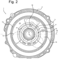
- Figure 2 shows a plan view of the gear assembly 1 from the motor side 6, and shows with dotted lines the gears 12 of a planetary gear system.
- the housing 2 comprises an inner wall 13 that can with its end face sealingly engage with a rear wall at the motor side 6 to form an oil reservoir 14 for the gears 12.
- an annular groove 15 is provided that forms an air channel that is in fluid communication with a breather opening 16.
- the breather opening 16 is provided in an upper part 17 of the oil reservoir 14, situated above the transverse center line 18.
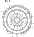
- Figure 3 shows a plate 20 in the oil reservoir 14, covering the annular groove 15.
- the plate 20 is of generally circular shape and has a perimeter 21 that extends in close proximity to the circumferential wall 4.
- the plate has two air/oil inlets 23,24 in the upper part 17 of the oil reservoir 14, and two air/oil inlets and outlets 25, 26 in a lower part 19 of the oil reservoir 14, situated below the transverse center line 18.
- the air/oil inlet and outlet 25 extends in both the upper part 17 and the lower part 19.
- the plate 20 is connected to an air distribution member 30, that is parallel to the circumferential wall 4 and that has three air inlet openings 31,32, 33.
- the plate 20 is fixed to an annular front wall surface 36 via the connecting flange 35.
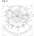
- Figure 4 shows the plate 20 on an enlarged scale with the circular perimeter 21 extending at a distance r from the axial center line 7.
- the distance r of the perimeter 21 is for instance 10-20 cm.
- the air inlet 23 is provided at an angle ⁇ 1 of about 10° and has a length L1 of for instance 3mm.
- the air inlet 24 is provided at an angle ⁇ 2 of 145° and may have a length L2 3mm.
- the air/oil inlet and outlet 25 is provided at an angle ⁇ 3 of 190° and may have a length L3 of 6.5 cm.
- the air/oil inlet and outlet 26 is provided at an angle ⁇ 4 of 340° and may have a length L4 of 3 cm.
- the distances r 1 -r 4 of the bottom of the recesses in the perimeter 21 that form the inlets and outlets 23-26 may be for instance 0.5cm smaller that the distance r of the perimeter 21.
Landscapes
- Engineering & Computer Science (AREA)
- General Engineering & Computer Science (AREA)
- Mechanical Engineering (AREA)
- Chemical & Material Sciences (AREA)
- Combustion & Propulsion (AREA)
- Transportation (AREA)
- General Details Of Gearings (AREA)
Description
- The invention relates to a transmission gear assembly comprising a housing with an axial center line, the housing having a circumferential wall extending in an axial direction, an end wall at a motor side and a front wall at an output side, the end wall and the front wall extending in a radial direction, the walls defining an oil reservoir having an upper part and a lower part,
- an opening being provided in the end wall for receiving an input shaft,
- a gear system being rotatably mounted in the housing and connectable to the input shaft,
- an opening being provided in the front wall for receiving an output shaft that is connectable to the gear system, and
- a breather opening being provided in the circumferential wall.
- The invention also relates to an electric motor connected to such a transmission gear assembly and to an electric vehicle comprising an electric motor and connected transmission gear assembly.
- In transmission gear assemblies, pressure builds up as a consequence of temperature variations. In the transmission gear housing, a breather opening is provided for pressure equalization with the ambient. Air can pass through the breather into and out of the transmission housing while contaminations are prevented from entering and oil is prevented from escaping from the transmission housing. An example of a transmission gear assembly is shown in
WO2015011976A . - For a breather to properly function, a calm area in the oil reservoir is required, especially in the case of concentric planetary gears that are subject to a relatively high degree of oil splashing. In such a case there are no naturally calm areas of the housing to place the breather. Proper placement of a breather becomes more complex when considering, in the design, the factors of: the temperature range and resulting oil viscosity variations; the speed of rotation for forward and reverse driving and the G-forces caused by acceleration; uphill and downhill driving, breaking and turning.
- It is known to provide ring-shaped channels in the oil reservoir of a transmission that are in fluid communication with a breather through a complex system of labyrinth passages that prevent oil from reaching the breather and escaping to ambient. These known constructions are of relatively large volume which makes it hard to package such a transmission gear assembly in a vehicle.
- It is an object of the invention to provide a transmission gear assembly in which the breather is effectively shielded from the oil in the reservoir while allowing a compact construction having a relatively large volume available for accommodating the gears. It is an aim of the invention to provide a transmission gear assembly of a relatively simple design, reducing the number of parts and being suitable for a large variety of transmission gears with minor tuning. It is again an object of the invention to provide a compact transmission gear assembly with a relatively large calm area.
- Hereto a transmission gear assembly according to the invention has a front wall comprising an annular groove that is in fluid communication with the breather opening at an upper side of the front wall, the annular groove being covered by a substantially circular plate having a perimeter at a first distance from the axial center line and with a predetermined length, the perimeter extending near the circumferential wall, with on each transverse side of the axial center line in at least the lower part an air/oil inlet and outlet defined by a recess of the perimeter at a distance from the axial center line that is smaller than the first distance, each recess having a circumferential length and being in fluid communication with the annular groove, and with on each transverse side of the center line in the upper part an air/oil inlet defined by a recess of the perimeter at a distance from the axial center line that is smaller than the first distance and having a circumferential length that is shorter than the circumferential length of the inlet/outlets.
- The calm area of the oil in the reservoir according to the invention is defined by the annular groove and the covering plate overlying the groove, with the peripheral air and oil apertures in the plate providing controlled flow and separation of oil and air. This results in a compact and stable breather design that works well for transmission gears, in particular co-axial or in line planetary transmission gears, of varying designs.
- An embodiment of a transmission gear according to the invention, comprises an air distribution member having air inlet openings that are situated along the circumferential wall in the lower part.
- The air inlet openings allow a controlled flow of air to travel to the front part of the housing defined by the circumferential wall and the front wall, and from there along the perimeter of the plate into the annular groove, and from there to the breather opening.
- In a particular advantageous embodiment of a transmission gear assembly according to the invention,
- a first inlet slot is situated with a midpoint at an angular position of between 35 and 55 (degrees and has a length l1 between 1% and 5 % of the length of the perimeter,
- a second inlet slot is situated with a midpoint at an angular position of between 130 and 150 degrees and has a length l2 between 1% and 5 % of the length of the perimeter,
- a first inlet/outlet slot is situated with a midpoint at an angular position of between 210 and 230 degrees and has a length l3 between 10% and 25 % of the length of the perimeter, and
- a second inlet/outlet slot is situated with a midpoint at an angular position of between 305 and 325 degrees, and has a length l4 between 5% and 20 % of the length of the perimeter.
-
-
Fig. 1 shows an isometric view of the housing of a transmission gear assembly according to the invention, -
Fig. 2 shows a plan view of the housing according to the invention form a motor side, with the plate removed, -
Fig. 3 shows the plan view of the housing offigure 2 , with the plate installed, and -
Fig. 4 shows the view offig. 3 on an enlarged scale. -
Figure 1 shows an isometric view of ahousing 2 of agear assembly 1 with anaxial center line 7. The housing has afront wall 3 and acircumferential wall 4. Thefront wall 3 extends in the radial direction R and is provided with anopening 5 through which a drive axle of a motor (not shown) can pass, the axle extending in the axial direction A. The motor is attached to thehousing 2 at amotor side 6. Thehousing 2 comprises abreather 8 that is closed by a cap 9. Through thebreather 8, air can travel between the interior of thehousing 2 and the ambient for pressure equalization, while its construction prevents oil from exiting from the gear assembly and dirt and water from entering. -
Figure 2 shows a plan view of thegear assembly 1 from themotor side 6, and shows with dotted lines thegears 12 of a planetary gear system. Thehousing 2 comprises aninner wall 13 that can with its end face sealingly engage with a rear wall at themotor side 6 to form anoil reservoir 14 for thegears 12. At thefront wall 3, anannular groove 15 is provided that forms an air channel that is in fluid communication with a breather opening 16. Thebreather opening 16 is provided in anupper part 17 of theoil reservoir 14, situated above the transverse center line 18. -
Figure 3 shows aplate 20 in theoil reservoir 14, covering theannular groove 15. Theplate 20 is of generally circular shape and has aperimeter 21 that extends in close proximity to thecircumferential wall 4. The plate has two air/oil inlets upper part 17 of theoil reservoir 14, and two air/oil inlets andoutlets lower part 19 of theoil reservoir 14, situated below the transverse center line 18. The air/oil inlet andoutlet 25 extends in both theupper part 17 and thelower part 19. - The
plate 20 is connected to anair distribution member 30, that is parallel to thecircumferential wall 4 and that has threeair inlet openings plate 20 is fixed to an annularfront wall surface 36 via the connectingflange 35. -
Figure 4 shows theplate 20 on an enlarged scale with thecircular perimeter 21 extending at a distance r from theaxial center line 7. The distance r of theperimeter 21 is for instance 10-20 cm. Theair inlet 23 is provided at an angle α1 of about 10° and has a length L1 of for instance 3mm. Theair inlet 24 is provided at an angle α2 of 145° and may have a length L2 3mm. The air/oil inlet andoutlet 25 is provided at an angle α3 of 190° and may have a length L3 of 6.5 cm. The air/oil inlet andoutlet 26 is provided at an angle α4 of 340° and may have a length L4 of 3 cm. The distances r1-r4 of the bottom of the recesses in theperimeter 21 that form the inlets and outlets 23-26 may be for instance 0.5cm smaller that the distance r of theperimeter 21.
Claims (7)
- Transmission gear assembly (1) comprising a housing (2) with an axial center line (7), the housing having a circumferential wall (4) extending in an axial direction, an end wall at a motor side (6) and a front wall (3) at an output side, the end wall and the front wall extending in a radial direction, the walls defining an oil reservoir (14) having an upper part (17) and a lower part (19),- an opening being provided in the end wall for receiving an input shaft,- a gear system (12) being rotatably mounted in the housing (2) and connectable to the input shaft,- an opening (5) being provided in the front wall (3) for receiving an output shaft that is connectable to the gear system (12),- a breather opening (8,16) being provided in the circumferential wall (4),the transmission gear assembly characterized in that the front wall (3) comprises an annular groove (15) that is in fluid communication with the breather opening (8,16) at an upper side of the front wall (3), the annular groove (15) being covered by a substantially circular plate (20) having a perimeter (21) at a first distance (r) from the axial center line (7), the perimeter (21) having a predetermined length and extending near the circumferential wall (4), with on each transverse side of the axial center line (7) in at least the lower part (19) an air/oil inlet and outlet (25,26) defined by a recess of the perimeter (21) at a distance (r3,r4) from the axial center (7) line that is smaller than the first distance r, each recess having a circumferential length (L3,L4) and being in fluid communication with the annular groove (15), and with on each transverse side of the axial center line (7) in the upper part (17) an air/oil inlet (23,24) is defined by a recess of the perimeter (21) at a distance (r1,r2) from the axial center line (7) that is smaller than the first distance (r) and having a circumferential length (L1,L2) that is shorter than the circumferential length (L3,L4) of the inlet/outlets (25,26).
- Transmission gear assembly (1) according to claim 1, an air distribution member (30) having air inlet openings (31,32,33), being situated along the circumferential wall (4) in the lower part (19) of the oil reservoir (14).
- Transmission gear assembly (1) according to claim 2, the air distribution member (30) being attached to the perimeter (21) of the plate (20), along a lower side.
- Transmission gear assembly (1) according to claim 1,2 or 3 wherein- a first inlet (23) is situated with a midpoint at an angular position of between 35 and 55 degrees and has a length L1 of between 1% and 5 % of the predetermined length of the perimeter (21),- a second inlet (24) is situated with a midpoint at an angular position of between 130 and 150 degrees and has a length L2 of between 1% and 5 % of the predetermined length of the perimeter (21),- a first inlet/outlet (25) is situated with a midpoint at an angular position of between 210 and 230 degrees and has a length L3 between 10% and 25 % of the predetermined length of the perimeter (21), and- a second inlet/outlet (26) is situated with a midpoint at an angular position of between 305 and 325 degrees, and has a length L4 between 5% and 20 % of the predetermined length of the perimeter (21).
- Transmission gear assembly (1) according to any of the preceding claims comprising a planetary gear system (12).
- Assembly of an electric motor with an output shaft, connected to the transmission gear assembly (1) according to any or the preceding claims, the output shaft of the electric motor being situated on the axial center line (7).
- Electric vehicle comprising the assembly of claim 6.
Priority Applications (3)
| Application Number | Priority Date | Filing Date | Title |
|---|---|---|---|
| EP21175369.4A EP4092293B1 (en) | 2021-05-21 | 2021-05-21 | Transmission gear assembly with a breather cavity |
| US17/747,023 US11879537B2 (en) | 2021-05-21 | 2022-05-18 | Transmission gear assembly with a breather cavity |
| CN202210553383.XA CN115388154B (en) | 2021-05-21 | 2022-05-20 | Transmission gear assembly with ventilation cavity |
Applications Claiming Priority (1)
| Application Number | Priority Date | Filing Date | Title |
|---|---|---|---|
| EP21175369.4A EP4092293B1 (en) | 2021-05-21 | 2021-05-21 | Transmission gear assembly with a breather cavity |
Publications (2)
| Publication Number | Publication Date |
|---|---|
| EP4092293A1 EP4092293A1 (en) | 2022-11-23 |
| EP4092293B1 true EP4092293B1 (en) | 2024-08-21 |
Family
ID=76059792
Family Applications (1)
| Application Number | Title | Priority Date | Filing Date |
|---|---|---|---|
| EP21175369.4A Active EP4092293B1 (en) | 2021-05-21 | 2021-05-21 | Transmission gear assembly with a breather cavity |
Country Status (3)
| Country | Link |
|---|---|
| US (1) | US11879537B2 (en) |
| EP (1) | EP4092293B1 (en) |
| CN (1) | CN115388154B (en) |
Family Cites Families (13)
| Publication number | Priority date | Publication date | Assignee | Title |
|---|---|---|---|---|
| JP2003161363A (en) * | 2001-11-27 | 2003-06-06 | Honda Motor Co Ltd | Breather apparatus for power train of electric automobile |
| JP2008014406A (en) * | 2006-07-06 | 2008-01-24 | Jatco Ltd | Automatic transmission |
| GB2466179A (en) * | 2008-12-05 | 2010-06-16 | Gm Global Tech Operations Inc | Casing having a breather duct with a tank for balancing pressure changes |
| JP5059920B2 (en) * | 2010-08-31 | 2012-10-31 | ジヤトコ株式会社 | Automatic transmission |
| US8783393B2 (en) * | 2011-02-25 | 2014-07-22 | Deere & Company | Interface for a motor and drive assembly |
| JP6137317B2 (en) * | 2013-07-24 | 2017-05-31 | 日産自動車株式会社 | Drive transmission device |
| WO2017102027A1 (en) * | 2015-12-18 | 2017-06-22 | Volvo Truck Corporation | Filter element comprising two offset outlets in communication with filter inner space, as well as corresponding housing |
| DE102016000857A1 (en) * | 2016-01-28 | 2017-08-03 | Mann + Hummel Gmbh | Housing, fluid outlet sealing member, housing cover and connecting part of a device for the separation of at least one fluid from gas and device and device for the separation of a fluid |
| JP6551389B2 (en) * | 2016-12-27 | 2019-07-31 | トヨタ自動車株式会社 | Hybrid vehicle lubrication structure |
| JP2018146000A (en) * | 2017-03-03 | 2018-09-20 | Ntn株式会社 | Breather structure of vehicle motor driving device and in-wheel motor driving device including the same |
| DE102018112315A1 (en) * | 2017-06-06 | 2018-12-06 | Schaeffler Technologies AG & Co. KG | Apparatus for exchanging gases |
| FR3090394B1 (en) * | 2018-12-19 | 2021-12-24 | Safran Trans Systems | Device for separating an air/oil mixture |
| JP7272101B2 (en) * | 2019-05-14 | 2023-05-12 | スズキ株式会社 | Vehicle drive system |
-
2021
- 2021-05-21 EP EP21175369.4A patent/EP4092293B1/en active Active
-
2022
- 2022-05-18 US US17/747,023 patent/US11879537B2/en active Active
- 2022-05-20 CN CN202210553383.XA patent/CN115388154B/en active Active
Also Published As
| Publication number | Publication date |
|---|---|
| EP4092293A1 (en) | 2022-11-23 |
| US11879537B2 (en) | 2024-01-23 |
| CN115388154B (en) | 2025-06-24 |
| CN115388154A (en) | 2022-11-25 |
| US20220373075A1 (en) | 2022-11-24 |
Similar Documents
| Publication | Publication Date | Title |
|---|---|---|
| US20030098204A1 (en) | Breather device for power train of electric vehicle | |
| CN111853210B (en) | Transmission with transmission housing having an exhaust system for commercial vehicles | |
| US10634234B2 (en) | Transmission | |
| KR20110100165A (en) | Air breather mechanism of the transmission | |
| EP1956272B1 (en) | Gear unit and lubricating oil splash preventing method | |
| EP4092293B1 (en) | Transmission gear assembly with a breather cavity | |
| US20240318717A1 (en) | Compact arrangement of e-drive reducer lubrication gutter | |
| KR20120022057A (en) | Automatic transmission | |
| US10792598B2 (en) | Breather | |
| JPH0948251A (en) | Vehicle drive configuration | |
| CN101240841B (en) | Gear unit and lubricating oil splash preventing method | |
| CN111417798B (en) | Drive train unit with internal lubrication system | |
| US10731746B2 (en) | Power transmission apparatus | |
| JP4459854B2 (en) | Automatic transmission | |
| KR101618464B1 (en) | Installation structure of air breather for casing of decelerator | |
| JP2005291263A (en) | Belt type continuously variable transmission | |
| US10731714B2 (en) | Power transmission apparatus | |
| EP3232089B1 (en) | Tractor with improved clutch housing | |
| JP6595118B2 (en) | Air breather chamber structure | |
| US4838764A (en) | Oil pump for transaxle | |
| JP7431056B2 (en) | transaxle structure | |
| KR102081001B1 (en) | Housing for 4WD Automotive Power Take-off Unit | |
| US20240157997A1 (en) | Dust cap for steering system | |
| JP6179272B2 (en) | Vehicle transmission | |
| US12176796B2 (en) | Drive unit and vehicle with a drive unit |
Legal Events
| Date | Code | Title | Description |
|---|---|---|---|
| PUAI | Public reference made under article 153(3) epc to a published international application that has entered the european phase |
Free format text: ORIGINAL CODE: 0009012 |
|
| STAA | Information on the status of an ep patent application or granted ep patent |
Free format text: STATUS: THE APPLICATION HAS BEEN PUBLISHED |
|
| AK | Designated contracting states |
Kind code of ref document: A1 Designated state(s): AL AT BE BG CH CY CZ DE DK EE ES FI FR GB GR HR HU IE IS IT LI LT LU LV MC MK MT NL NO PL PT RO RS SE SI SK SM TR |
|
| STAA | Information on the status of an ep patent application or granted ep patent |
Free format text: STATUS: REQUEST FOR EXAMINATION WAS MADE |
|
| 17P | Request for examination filed |
Effective date: 20230522 |
|
| RBV | Designated contracting states (corrected) |
Designated state(s): AL AT BE BG CH CY CZ DE DK EE ES FI FR GB GR HR HU IE IS IT LI LT LU LV MC MK MT NL NO PL PT RO RS SE SI SK SM TR |
|
| GRAP | Despatch of communication of intention to grant a patent |
Free format text: ORIGINAL CODE: EPIDOSNIGR1 |
|
| STAA | Information on the status of an ep patent application or granted ep patent |
Free format text: STATUS: GRANT OF PATENT IS INTENDED |
|
| INTG | Intention to grant announced |
Effective date: 20240325 |
|
| GRAS | Grant fee paid |
Free format text: ORIGINAL CODE: EPIDOSNIGR3 |
|
| GRAA | (expected) grant |
Free format text: ORIGINAL CODE: 0009210 |
|
| STAA | Information on the status of an ep patent application or granted ep patent |
Free format text: STATUS: THE PATENT HAS BEEN GRANTED |
|
| AK | Designated contracting states |
Kind code of ref document: B1 Designated state(s): AL AT BE BG CH CY CZ DE DK EE ES FI FR GB GR HR HU IE IS IT LI LT LU LV MC MK MT NL NO PL PT RO RS SE SI SK SM TR |
|
| P01 | Opt-out of the competence of the unified patent court (upc) registered |
Free format text: CASE NUMBER: APP_41264/2024 Effective date: 20240712 |
|
| REG | Reference to a national code |
Ref country code: GB Ref legal event code: FG4D |
|
| REG | Reference to a national code |
Ref country code: CH Ref legal event code: EP |
|
| REG | Reference to a national code |
Ref country code: DE Ref legal event code: R096 Ref document number: 602021017404 Country of ref document: DE |
|
| REG | Reference to a national code |
Ref country code: IE Ref legal event code: FG4D |
|
| REG | Reference to a national code |
Ref country code: LT Ref legal event code: MG9D |
|
| REG | Reference to a national code |
Ref country code: NL Ref legal event code: MP Effective date: 20240821 |
|
| PG25 | Lapsed in a contracting state [announced via postgrant information from national office to epo] |
Ref country code: NO Free format text: LAPSE BECAUSE OF FAILURE TO SUBMIT A TRANSLATION OF THE DESCRIPTION OR TO PAY THE FEE WITHIN THE PRESCRIBED TIME-LIMIT Effective date: 20241121 |
|
| REG | Reference to a national code |
Ref country code: AT Ref legal event code: MK05 Ref document number: 1715752 Country of ref document: AT Kind code of ref document: T Effective date: 20240821 |
|
| PG25 | Lapsed in a contracting state [announced via postgrant information from national office to epo] |
Ref country code: PT Free format text: LAPSE BECAUSE OF FAILURE TO SUBMIT A TRANSLATION OF THE DESCRIPTION OR TO PAY THE FEE WITHIN THE PRESCRIBED TIME-LIMIT Effective date: 20241223 Ref country code: GR Free format text: LAPSE BECAUSE OF FAILURE TO SUBMIT A TRANSLATION OF THE DESCRIPTION OR TO PAY THE FEE WITHIN THE PRESCRIBED TIME-LIMIT Effective date: 20241122 Ref country code: NL Free format text: LAPSE BECAUSE OF FAILURE TO SUBMIT A TRANSLATION OF THE DESCRIPTION OR TO PAY THE FEE WITHIN THE PRESCRIBED TIME-LIMIT Effective date: 20240821 Ref country code: PL Free format text: LAPSE BECAUSE OF FAILURE TO SUBMIT A TRANSLATION OF THE DESCRIPTION OR TO PAY THE FEE WITHIN THE PRESCRIBED TIME-LIMIT Effective date: 20240821 Ref country code: FI Free format text: LAPSE BECAUSE OF FAILURE TO SUBMIT A TRANSLATION OF THE DESCRIPTION OR TO PAY THE FEE WITHIN THE PRESCRIBED TIME-LIMIT Effective date: 20240821 |
|
| PG25 | Lapsed in a contracting state [announced via postgrant information from national office to epo] |
Ref country code: BG Free format text: LAPSE BECAUSE OF FAILURE TO SUBMIT A TRANSLATION OF THE DESCRIPTION OR TO PAY THE FEE WITHIN THE PRESCRIBED TIME-LIMIT Effective date: 20240821 |
|
| PG25 | Lapsed in a contracting state [announced via postgrant information from national office to epo] |
Ref country code: LV Free format text: LAPSE BECAUSE OF FAILURE TO SUBMIT A TRANSLATION OF THE DESCRIPTION OR TO PAY THE FEE WITHIN THE PRESCRIBED TIME-LIMIT Effective date: 20240821 |
|
| PG25 | Lapsed in a contracting state [announced via postgrant information from national office to epo] |
Ref country code: IS Free format text: LAPSE BECAUSE OF FAILURE TO SUBMIT A TRANSLATION OF THE DESCRIPTION OR TO PAY THE FEE WITHIN THE PRESCRIBED TIME-LIMIT Effective date: 20241221 Ref country code: AT Free format text: LAPSE BECAUSE OF FAILURE TO SUBMIT A TRANSLATION OF THE DESCRIPTION OR TO PAY THE FEE WITHIN THE PRESCRIBED TIME-LIMIT Effective date: 20240821 |
|
| PG25 | Lapsed in a contracting state [announced via postgrant information from national office to epo] |
Ref country code: HR Free format text: LAPSE BECAUSE OF FAILURE TO SUBMIT A TRANSLATION OF THE DESCRIPTION OR TO PAY THE FEE WITHIN THE PRESCRIBED TIME-LIMIT Effective date: 20240821 |
|
| PG25 | Lapsed in a contracting state [announced via postgrant information from national office to epo] |
Ref country code: ES Free format text: LAPSE BECAUSE OF FAILURE TO SUBMIT A TRANSLATION OF THE DESCRIPTION OR TO PAY THE FEE WITHIN THE PRESCRIBED TIME-LIMIT Effective date: 20240821 Ref country code: RS Free format text: LAPSE BECAUSE OF FAILURE TO SUBMIT A TRANSLATION OF THE DESCRIPTION OR TO PAY THE FEE WITHIN THE PRESCRIBED TIME-LIMIT Effective date: 20241121 |
|
| PG25 | Lapsed in a contracting state [announced via postgrant information from national office to epo] |
Ref country code: RS Free format text: LAPSE BECAUSE OF FAILURE TO SUBMIT A TRANSLATION OF THE DESCRIPTION OR TO PAY THE FEE WITHIN THE PRESCRIBED TIME-LIMIT Effective date: 20241121 Ref country code: PT Free format text: LAPSE BECAUSE OF FAILURE TO SUBMIT A TRANSLATION OF THE DESCRIPTION OR TO PAY THE FEE WITHIN THE PRESCRIBED TIME-LIMIT Effective date: 20241223 Ref country code: PL Free format text: LAPSE BECAUSE OF FAILURE TO SUBMIT A TRANSLATION OF THE DESCRIPTION OR TO PAY THE FEE WITHIN THE PRESCRIBED TIME-LIMIT Effective date: 20240821 Ref country code: NO Free format text: LAPSE BECAUSE OF FAILURE TO SUBMIT A TRANSLATION OF THE DESCRIPTION OR TO PAY THE FEE WITHIN THE PRESCRIBED TIME-LIMIT Effective date: 20241121 Ref country code: NL Free format text: LAPSE BECAUSE OF FAILURE TO SUBMIT A TRANSLATION OF THE DESCRIPTION OR TO PAY THE FEE WITHIN THE PRESCRIBED TIME-LIMIT Effective date: 20240821 Ref country code: LV Free format text: LAPSE BECAUSE OF FAILURE TO SUBMIT A TRANSLATION OF THE DESCRIPTION OR TO PAY THE FEE WITHIN THE PRESCRIBED TIME-LIMIT Effective date: 20240821 Ref country code: IS Free format text: LAPSE BECAUSE OF FAILURE TO SUBMIT A TRANSLATION OF THE DESCRIPTION OR TO PAY THE FEE WITHIN THE PRESCRIBED TIME-LIMIT Effective date: 20241221 Ref country code: HR Free format text: LAPSE BECAUSE OF FAILURE TO SUBMIT A TRANSLATION OF THE DESCRIPTION OR TO PAY THE FEE WITHIN THE PRESCRIBED TIME-LIMIT Effective date: 20240821 Ref country code: GR Free format text: LAPSE BECAUSE OF FAILURE TO SUBMIT A TRANSLATION OF THE DESCRIPTION OR TO PAY THE FEE WITHIN THE PRESCRIBED TIME-LIMIT Effective date: 20241122 Ref country code: FI Free format text: LAPSE BECAUSE OF FAILURE TO SUBMIT A TRANSLATION OF THE DESCRIPTION OR TO PAY THE FEE WITHIN THE PRESCRIBED TIME-LIMIT Effective date: 20240821 Ref country code: ES Free format text: LAPSE BECAUSE OF FAILURE TO SUBMIT A TRANSLATION OF THE DESCRIPTION OR TO PAY THE FEE WITHIN THE PRESCRIBED TIME-LIMIT Effective date: 20240821 Ref country code: BG Free format text: LAPSE BECAUSE OF FAILURE TO SUBMIT A TRANSLATION OF THE DESCRIPTION OR TO PAY THE FEE WITHIN THE PRESCRIBED TIME-LIMIT Effective date: 20240821 Ref country code: AT Free format text: LAPSE BECAUSE OF FAILURE TO SUBMIT A TRANSLATION OF THE DESCRIPTION OR TO PAY THE FEE WITHIN THE PRESCRIBED TIME-LIMIT Effective date: 20240821 |
|
| PG25 | Lapsed in a contracting state [announced via postgrant information from national office to epo] |
Ref country code: RO Free format text: LAPSE BECAUSE OF FAILURE TO SUBMIT A TRANSLATION OF THE DESCRIPTION OR TO PAY THE FEE WITHIN THE PRESCRIBED TIME-LIMIT Effective date: 20240821 Ref country code: DK Free format text: LAPSE BECAUSE OF FAILURE TO SUBMIT A TRANSLATION OF THE DESCRIPTION OR TO PAY THE FEE WITHIN THE PRESCRIBED TIME-LIMIT Effective date: 20240821 Ref country code: SM Free format text: LAPSE BECAUSE OF FAILURE TO SUBMIT A TRANSLATION OF THE DESCRIPTION OR TO PAY THE FEE WITHIN THE PRESCRIBED TIME-LIMIT Effective date: 20240821 |
|
| PG25 | Lapsed in a contracting state [announced via postgrant information from national office to epo] |
Ref country code: EE Free format text: LAPSE BECAUSE OF FAILURE TO SUBMIT A TRANSLATION OF THE DESCRIPTION OR TO PAY THE FEE WITHIN THE PRESCRIBED TIME-LIMIT Effective date: 20240821 |
|
| PG25 | Lapsed in a contracting state [announced via postgrant information from national office to epo] |
Ref country code: CZ Free format text: LAPSE BECAUSE OF FAILURE TO SUBMIT A TRANSLATION OF THE DESCRIPTION OR TO PAY THE FEE WITHIN THE PRESCRIBED TIME-LIMIT Effective date: 20240821 |
|
| PG25 | Lapsed in a contracting state [announced via postgrant information from national office to epo] |
Ref country code: IT Free format text: LAPSE BECAUSE OF FAILURE TO SUBMIT A TRANSLATION OF THE DESCRIPTION OR TO PAY THE FEE WITHIN THE PRESCRIBED TIME-LIMIT Effective date: 20240821 Ref country code: SK Free format text: LAPSE BECAUSE OF FAILURE TO SUBMIT A TRANSLATION OF THE DESCRIPTION OR TO PAY THE FEE WITHIN THE PRESCRIBED TIME-LIMIT Effective date: 20240821 |
|
| REG | Reference to a national code |
Ref country code: DE Ref legal event code: R097 Ref document number: 602021017404 Country of ref document: DE |
|
| PLBE | No opposition filed within time limit |
Free format text: ORIGINAL CODE: 0009261 |
|
| STAA | Information on the status of an ep patent application or granted ep patent |
Free format text: STATUS: NO OPPOSITION FILED WITHIN TIME LIMIT |
|
| PGFP | Annual fee paid to national office [announced via postgrant information from national office to epo] |
Ref country code: DE Payment date: 20250423 Year of fee payment: 5 |
|
| PGFP | Annual fee paid to national office [announced via postgrant information from national office to epo] |
Ref country code: GB Payment date: 20250423 Year of fee payment: 5 |
|
| PGFP | Annual fee paid to national office [announced via postgrant information from national office to epo] |
Ref country code: FR Payment date: 20250423 Year of fee payment: 5 |
|
| 26N | No opposition filed |
Effective date: 20250522 |
|
| PG25 | Lapsed in a contracting state [announced via postgrant information from national office to epo] |
Ref country code: SE Free format text: LAPSE BECAUSE OF FAILURE TO SUBMIT A TRANSLATION OF THE DESCRIPTION OR TO PAY THE FEE WITHIN THE PRESCRIBED TIME-LIMIT Effective date: 20240821 |
|
| REG | Reference to a national code |
Ref country code: CH Ref legal event code: H13 Free format text: ST27 STATUS EVENT CODE: U-0-0-H10-H13 (AS PROVIDED BY THE NATIONAL OFFICE) Effective date: 20251223 |
|
| PG25 | Lapsed in a contracting state [announced via postgrant information from national office to epo] |
Ref country code: LU Free format text: LAPSE BECAUSE OF NON-PAYMENT OF DUE FEES Effective date: 20250521 |
|
| PG25 | Lapsed in a contracting state [announced via postgrant information from national office to epo] |
Ref country code: CH Free format text: LAPSE BECAUSE OF NON-PAYMENT OF DUE FEES Effective date: 20250531 |
|
| REG | Reference to a national code |
Ref country code: BE Ref legal event code: MM Effective date: 20250531 |
|
| PG25 | Lapsed in a contracting state [announced via postgrant information from national office to epo] |
Ref country code: MC Free format text: LAPSE BECAUSE OF FAILURE TO SUBMIT A TRANSLATION OF THE DESCRIPTION OR TO PAY THE FEE WITHIN THE PRESCRIBED TIME-LIMIT Effective date: 20240821 |
|
| PG25 | Lapsed in a contracting state [announced via postgrant information from national office to epo] |
Ref country code: IE Free format text: LAPSE BECAUSE OF NON-PAYMENT OF DUE FEES Effective date: 20250521 |
|
| PG25 | Lapsed in a contracting state [announced via postgrant information from national office to epo] |
Ref country code: BE Free format text: LAPSE BECAUSE OF NON-PAYMENT OF DUE FEES Effective date: 20250531 |