EP4092256A1 - Abgasanlage einer verbrennungskraftmaschine - Google Patents
Abgasanlage einer verbrennungskraftmaschine Download PDFInfo
- Publication number
- EP4092256A1 EP4092256A1 EP22173546.7A EP22173546A EP4092256A1 EP 4092256 A1 EP4092256 A1 EP 4092256A1 EP 22173546 A EP22173546 A EP 22173546A EP 4092256 A1 EP4092256 A1 EP 4092256A1
- Authority
- EP
- European Patent Office
- Prior art keywords
- exhaust gas
- flow
- sensor
- exhaust
- guide vane
- Prior art date
- Legal status (The legal status is an assumption and is not a legal conclusion. Google has not performed a legal analysis and makes no representation as to the accuracy of the status listed.)
- Granted
Links
- 238000002485 combustion reaction Methods 0.000 title claims abstract description 27
- 239000000203 mixture Substances 0.000 claims abstract description 15
- 238000011144 upstream manufacturing Methods 0.000 claims abstract description 12
- 239000000523 sample Substances 0.000 claims description 40
- 239000007789 gas Substances 0.000 description 162
- 230000003197 catalytic effect Effects 0.000 description 22
- 230000001681 protective effect Effects 0.000 description 17
- MWUXSHHQAYIFBG-UHFFFAOYSA-N nitrogen oxide Inorganic materials O=[N] MWUXSHHQAYIFBG-UHFFFAOYSA-N 0.000 description 9
- QVGXLLKOCUKJST-UHFFFAOYSA-N atomic oxygen Chemical compound [O] QVGXLLKOCUKJST-UHFFFAOYSA-N 0.000 description 8
- 239000001301 oxygen Substances 0.000 description 8
- 229910052760 oxygen Inorganic materials 0.000 description 8
- 239000000446 fuel Substances 0.000 description 7
- 238000005259 measurement Methods 0.000 description 7
- 239000003344 environmental pollutant Substances 0.000 description 5
- 239000002245 particle Substances 0.000 description 5
- 231100000719 pollutant Toxicity 0.000 description 5
- 238000013461 design Methods 0.000 description 4
- 230000001133 acceleration Effects 0.000 description 3
- 239000003054 catalyst Substances 0.000 description 3
- 230000000694 effects Effects 0.000 description 3
- 239000012530 fluid Substances 0.000 description 3
- 230000015572 biosynthetic process Effects 0.000 description 2
- 238000010531 catalytic reduction reaction Methods 0.000 description 2
- 238000004140 cleaning Methods 0.000 description 2
- 238000009833 condensation Methods 0.000 description 2
- 230000005494 condensation Effects 0.000 description 2
- 230000001419 dependent effect Effects 0.000 description 2
- 230000009467 reduction Effects 0.000 description 2
- 238000006722 reduction reaction Methods 0.000 description 2
- 230000004044 response Effects 0.000 description 2
- 239000004071 soot Substances 0.000 description 2
- XSQUKJJJFZCRTK-UHFFFAOYSA-N Urea Chemical compound NC(N)=O XSQUKJJJFZCRTK-UHFFFAOYSA-N 0.000 description 1
- 238000010521 absorption reaction Methods 0.000 description 1
- 238000004458 analytical method Methods 0.000 description 1
- 239000006227 byproduct Substances 0.000 description 1
- 238000004364 calculation method Methods 0.000 description 1
- 239000004202 carbamide Substances 0.000 description 1
- 239000000919 ceramic Substances 0.000 description 1
- 230000008859 change Effects 0.000 description 1
- 238000006243 chemical reaction Methods 0.000 description 1
- 239000003638 chemical reducing agent Substances 0.000 description 1
- 230000007423 decrease Effects 0.000 description 1
- 238000001514 detection method Methods 0.000 description 1
- 238000011161 development Methods 0.000 description 1
- 230000018109 developmental process Effects 0.000 description 1
- 238000003745 diagnosis Methods 0.000 description 1
- 238000005516 engineering process Methods 0.000 description 1
- 229930195733 hydrocarbon Natural products 0.000 description 1
- 150000002430 hydrocarbons Chemical class 0.000 description 1
- 230000007246 mechanism Effects 0.000 description 1
- 238000013021 overheating Methods 0.000 description 1
- 230000003647 oxidation Effects 0.000 description 1
- 238000007254 oxidation reaction Methods 0.000 description 1
- 238000012545 processing Methods 0.000 description 1
- 239000007787 solid Substances 0.000 description 1
- 239000000126 substance Substances 0.000 description 1
- 230000007704 transition Effects 0.000 description 1
- XLYOFNOQVPJJNP-UHFFFAOYSA-N water Substances O XLYOFNOQVPJJNP-UHFFFAOYSA-N 0.000 description 1
Images


Classifications
-
- F—MECHANICAL ENGINEERING; LIGHTING; HEATING; WEAPONS; BLASTING
- F01—MACHINES OR ENGINES IN GENERAL; ENGINE PLANTS IN GENERAL; STEAM ENGINES
- F01N—GAS-FLOW SILENCERS OR EXHAUST APPARATUS FOR MACHINES OR ENGINES IN GENERAL; GAS-FLOW SILENCERS OR EXHAUST APPARATUS FOR INTERNAL COMBUSTION ENGINES
- F01N3/00—Exhaust or silencing apparatus having means for purifying, rendering innocuous, or otherwise treating exhaust
- F01N3/08—Exhaust or silencing apparatus having means for purifying, rendering innocuous, or otherwise treating exhaust for rendering innocuous
- F01N3/10—Exhaust or silencing apparatus having means for purifying, rendering innocuous, or otherwise treating exhaust for rendering innocuous by thermal or catalytic conversion of noxious components of exhaust
- F01N3/24—Exhaust or silencing apparatus having means for purifying, rendering innocuous, or otherwise treating exhaust for rendering innocuous by thermal or catalytic conversion of noxious components of exhaust characterised by constructional aspects of converting apparatus
- F01N3/28—Construction of catalytic reactors
- F01N3/2892—Exhaust flow directors or the like, e.g. upstream of catalytic device
-
- F—MECHANICAL ENGINEERING; LIGHTING; HEATING; WEAPONS; BLASTING
- F01—MACHINES OR ENGINES IN GENERAL; ENGINE PLANTS IN GENERAL; STEAM ENGINES
- F01N—GAS-FLOW SILENCERS OR EXHAUST APPARATUS FOR MACHINES OR ENGINES IN GENERAL; GAS-FLOW SILENCERS OR EXHAUST APPARATUS FOR INTERNAL COMBUSTION ENGINES
- F01N13/00—Exhaust or silencing apparatus characterised by constructional features ; Exhaust or silencing apparatus, or parts thereof, having pertinent characteristics not provided for in, or of interest apart from, groups F01N1/00 - F01N5/00, F01N9/00, F01N11/00
- F01N13/008—Mounting or arrangement of exhaust sensors in or on exhaust apparatus
-
- F—MECHANICAL ENGINEERING; LIGHTING; HEATING; WEAPONS; BLASTING
- F01—MACHINES OR ENGINES IN GENERAL; ENGINE PLANTS IN GENERAL; STEAM ENGINES
- F01N—GAS-FLOW SILENCERS OR EXHAUST APPARATUS FOR MACHINES OR ENGINES IN GENERAL; GAS-FLOW SILENCERS OR EXHAUST APPARATUS FOR INTERNAL COMBUSTION ENGINES
- F01N13/00—Exhaust or silencing apparatus characterised by constructional features ; Exhaust or silencing apparatus, or parts thereof, having pertinent characteristics not provided for in, or of interest apart from, groups F01N1/00 - F01N5/00, F01N9/00, F01N11/00
- F01N13/08—Other arrangements or adaptations of exhaust conduits
-
- F—MECHANICAL ENGINEERING; LIGHTING; HEATING; WEAPONS; BLASTING
- F01—MACHINES OR ENGINES IN GENERAL; ENGINE PLANTS IN GENERAL; STEAM ENGINES
- F01N—GAS-FLOW SILENCERS OR EXHAUST APPARATUS FOR MACHINES OR ENGINES IN GENERAL; GAS-FLOW SILENCERS OR EXHAUST APPARATUS FOR INTERNAL COMBUSTION ENGINES
- F01N2240/00—Combination or association of two or more different exhaust treating devices, or of at least one such device with an auxiliary device, not covered by indexing codes F01N2230/00 or F01N2250/00, one of the devices being
- F01N2240/20—Combination or association of two or more different exhaust treating devices, or of at least one such device with an auxiliary device, not covered by indexing codes F01N2230/00 or F01N2250/00, one of the devices being a flow director or deflector
-
- F—MECHANICAL ENGINEERING; LIGHTING; HEATING; WEAPONS; BLASTING
- F01—MACHINES OR ENGINES IN GENERAL; ENGINE PLANTS IN GENERAL; STEAM ENGINES
- F01N—GAS-FLOW SILENCERS OR EXHAUST APPARATUS FOR MACHINES OR ENGINES IN GENERAL; GAS-FLOW SILENCERS OR EXHAUST APPARATUS FOR INTERNAL COMBUSTION ENGINES
- F01N2260/00—Exhaust treating devices having provisions not otherwise provided for
- F01N2260/14—Exhaust treating devices having provisions not otherwise provided for for modifying or adapting flow area or back-pressure
-
- F—MECHANICAL ENGINEERING; LIGHTING; HEATING; WEAPONS; BLASTING
- F01—MACHINES OR ENGINES IN GENERAL; ENGINE PLANTS IN GENERAL; STEAM ENGINES
- F01N—GAS-FLOW SILENCERS OR EXHAUST APPARATUS FOR MACHINES OR ENGINES IN GENERAL; GAS-FLOW SILENCERS OR EXHAUST APPARATUS FOR INTERNAL COMBUSTION ENGINES
- F01N2560/00—Exhaust systems with means for detecting or measuring exhaust gas components or characteristics
- F01N2560/02—Exhaust systems with means for detecting or measuring exhaust gas components or characteristics the means being an exhaust gas sensor
- F01N2560/025—Exhaust systems with means for detecting or measuring exhaust gas components or characteristics the means being an exhaust gas sensor for measuring or detecting O2, e.g. lambda sensors
-
- F—MECHANICAL ENGINEERING; LIGHTING; HEATING; WEAPONS; BLASTING
- F01—MACHINES OR ENGINES IN GENERAL; ENGINE PLANTS IN GENERAL; STEAM ENGINES
- F01N—GAS-FLOW SILENCERS OR EXHAUST APPARATUS FOR MACHINES OR ENGINES IN GENERAL; GAS-FLOW SILENCERS OR EXHAUST APPARATUS FOR INTERNAL COMBUSTION ENGINES
- F01N2560/00—Exhaust systems with means for detecting or measuring exhaust gas components or characteristics
- F01N2560/02—Exhaust systems with means for detecting or measuring exhaust gas components or characteristics the means being an exhaust gas sensor
- F01N2560/026—Exhaust systems with means for detecting or measuring exhaust gas components or characteristics the means being an exhaust gas sensor for measuring or detecting NOx
-
- F—MECHANICAL ENGINEERING; LIGHTING; HEATING; WEAPONS; BLASTING
- F01—MACHINES OR ENGINES IN GENERAL; ENGINE PLANTS IN GENERAL; STEAM ENGINES
- F01N—GAS-FLOW SILENCERS OR EXHAUST APPARATUS FOR MACHINES OR ENGINES IN GENERAL; GAS-FLOW SILENCERS OR EXHAUST APPARATUS FOR INTERNAL COMBUSTION ENGINES
- F01N2560/00—Exhaust systems with means for detecting or measuring exhaust gas components or characteristics
- F01N2560/12—Other sensor principles, e.g. using electro conductivity of substrate or radio frequency
-
- Y—GENERAL TAGGING OF NEW TECHNOLOGICAL DEVELOPMENTS; GENERAL TAGGING OF CROSS-SECTIONAL TECHNOLOGIES SPANNING OVER SEVERAL SECTIONS OF THE IPC; TECHNICAL SUBJECTS COVERED BY FORMER USPC CROSS-REFERENCE ART COLLECTIONS [XRACs] AND DIGESTS
- Y02—TECHNOLOGIES OR APPLICATIONS FOR MITIGATION OR ADAPTATION AGAINST CLIMATE CHANGE
- Y02T—CLIMATE CHANGE MITIGATION TECHNOLOGIES RELATED TO TRANSPORTATION
- Y02T10/00—Road transport of goods or passengers
- Y02T10/10—Internal combustion engine [ICE] based vehicles
- Y02T10/12—Improving ICE efficiencies
Definitions
- the invention relates to an exhaust system of an internal combustion engine in a vehicle, which includes an exhaust gas duct and an exhaust gas aftertreatment system.
- Efficient operation and low pollutant emissions from motor vehicles are subject to constant analysis and consideration in order to reduce fuel consumption and exhaust emissions.
- both raw emissions are significantly reduced through internal engine measures and intelligent engine control concepts as well as emissions released into the environment through improved exhaust aftertreatment systems.
- An important part of achieving this goal is the control of combustion in the vehicle's internal combustion engine.
- the main by-products are the pollutants NO x , CO and HC.
- the amounts of these pollutants contained in the raw exhaust gas are highly dependent on the combustion process and engine operation.
- a variable that has a significant influence on the formation of pollutants is the air ratio ⁇ .
- the correct air ratio - also known as the lambda ratio - is an important parameter for controlling combustion and also for enabling exhaust gas cleaning by catalytic converters.
- the air ratio is 1 if the air mass supplied corresponds exactly to the air mass theoretically required for complete stoichiometric combustion of the fuel supplied.
- ⁇ 1
- An air ratio that is less than 1 is chosen to form a rich air-fuel mixture. This is done, among other things, to protect components in the exhaust system from overheating, e.g. B. to protect during long full-load trips.
- an air ratio greater than 1 can be selected. In this area there is excess air and the result is a lean air-fuel mixture.
- the HC and CO emissions are removed from the diesel exhaust gas by an oxidation catalytic converter.
- nitrogen oxides can be removed with a NOx storage catalytic converter or an SCR catalytic converter (Selective Catalytic Reduction). Soot particles are removed with the help of soot particle filters. In order to use these measures efficiently, the air ratio is varied from time to time.
- a NO x storage catalytic converter stores nitrogen oxides and must therefore be regenerated after a certain time or absorption quantity. For this, there must be a lack of air in the exhaust gas, since the substances CO, H 2 and various hydrocarbons present in the exhaust gas serve as reducing agents.
- Lambda sensors - also known as lambda probes - are used for this purpose, in which a distinction is made between step probes and linear probes (broadband probes).
- the step sensors allow the stoichiometric fuel-air ratio to be controlled around that with an air ratio equal to 1, since they detect the transition from one range to another.
- Broadband probes measure both in the rich and lean range.
- the lambda probe measures the residual oxygen content of the exhaust gas and sends the value in the form of an electrical voltage to the engine control unit. Based on the lambda probe voltage, the control unit recognizes the composition of the mixture and can set the combustion air ratio.
- Lambda sensors can be constructed in different ways. What all designs have in common, however, is that the exhaust gas to be measured flows around them.
- a protective tube is attached to the exhaust gas side of the probe housing to protect sensitive elements. This protects the sensor element from combustion residues and condensation in the exhaust gas.
- the protective tube is provided with holes for gas access. Accordingly, it is of great Meaning that, despite the protective tube, there can be sufficient contact between the measuring elements and the exhaust gas.
- NO x sensors can also be important for efficient exhaust aftertreatment to monitor nitrogen oxide emissions. This can be done by NO x sensors. These are used, among other things, to regulate the metered amount of urea in systems for selective catalytic reduction (SCR) to reduce NO x and to monitor (on-board diagnosis) the SCR components.
- SCR selective catalytic reduction
- the sensor also makes it possible to monitor a NOx storage catalytic converter.
- NO x sensors also include a ceramic sensor element that works according to the amperometric double-chamber principle and is protected by a protective tube.
- JP 2016-121652 A describes an internal combustion engine with an attached exhaust manifold. Starting from the cylinder head, the exhaust gas paths of the respective cylinders are connected via openings to corresponding exhaust gas lines of the exhaust gas manifold and finally open into an exhaust gas collecting pipe of the manifold, where a lambda probe is arranged. A gasket is positioned between the exhaust manifold and the cylinder head. In the area of the exhaust gas paths, the seal includes projections that protrude into the openings and direct the exhaust gas in the direction of the lambda probe.
- JP 2007-247560A describes an internal combustion engine with an exhaust gas turbocharger.
- a bypass line (also called a wastegate) is arranged downstream of the internal combustion engine and upstream of the turbine of the exhaust gas turbocharger, starting from an exhaust gas line, for charge pressure control.
- the bypass line has a bypass valve that adjusts the amount of exhaust gas that is supplied to the turbine.
- a sensor is arranged downstream of the bypass line and upstream of an exhaust gas catalytic converter. After a cold start, the bypass valve is opened to quickly heat the sensor to its operating temperature. So that the exhaust gas flows around the sensor, a guide means is arranged in the downstream area of the bypass line. These are lamellae that are arranged on the bypass valve.
- the guide means are imitated by the convex shape of the exhaust gas duct, which in other words is narrowed at the point mentioned.
- the guiding means are effective when the bypass valve is open, so that the flow passes through the point at which the guiding means is present.
- the invention is now based on the object of providing an exhaust system for an internal combustion engine of a vehicle which at least partially overcomes the disadvantages of the prior art mentioned and ensures that gas sensors for determining the gas composition, which are used in the exhaust systems, provide precise and reliable measured values .
- the exhaust system according to the invention for an internal combustion engine of a vehicle comprises an exhaust gas duct and an exhaust gas aftertreatment system, with at least one sensor for determining the exhaust gas composition being arranged in the exhaust gas duct. Furthermore, a guide vane is arranged upstream of the sensor, the guide vane being designed to increase the flow velocity of the exhaust gas in a local flow cross section of the exhaust gas duct at the level of the sensor.
- the exhaust gas system By increasing the flow speed of the exhaust gas, the exhaust gas is accelerated.
- the exhaust gas system according to the invention increases the flow speed of the exhaust gas in a local flow cross section of the exhaust gas duct at the level of the sensor.
- sensors for determining the exhaust gas composition which are arranged in the exhaust gas flow, include protective tubes which are intended to protect the sensors from combustion residues and water hammer.
- the protective tubes have openings through which the exhaust gas can enter the protective tubes. Accordingly, a sufficiently high flow rate of the exhaust gas at the protective tube of the sensors is desirable.
- the exchange rate of the gas depends to a large extent on the said flow rate.
- the guide vane is arranged upstream of the sensor. Furthermore, the guide vane is designed to increase the flow speed of the exhaust gas in a local flow cross section of the exhaust gas duct at the level of the sensor. This ensures that the flow rate of the exhaust gas that flows around the sensor and is in contact with it assumes sufficiently high values. As a result, it is achieved that the sensors provide accurate and reliable measurement values.
- the enthalpy contained in the exhaust gas that flows over the guide vane is either completely or partially converted into flow energy by the guide vane. The force to accelerate the fluid particles, the pressure gradient force and their work leads to the increase in the kinetic energy of the fluid particles. In other words, the exhaust gas is accelerated by the energy conversion.
- the flow rate of the exhaust gas in the exhaust gas duct is increased at the level of the sensor.
- this local restriction of influencing the flow field of the exhaust gas means that the exhaust gas back pressure is only influenced to a small extent. In particular, this influence occurs exclusively there, where the exhaust gas flow influences the measurement. Other areas remain unaffected.
- the flow cross section of the exhaust gas duct is constant at the height of the sensor.
- constrictions in the area of the sensor that are usual in the prior art can thus be avoided.
- this also enables a space-saving solution that also makes structural adjustments to an entire section of the exhaust gas duct superfluous and therefore also represents an economically more cost-effective solution.
- the sensor for determining the exhaust gas composition is a lambda probe.
- the sensor for determining the exhaust gas composition is an NO x sensor.
- Both sensor types have in common that they contain sensitive measuring elements that require special protection, which is provided by protective tubes.
- these sensors enable optimized operation of the internal combustion engine, which is ensured by precise and reliable measurement due to the sufficiently high flow velocities. At the same time, the sensors are always protected by their design and thus have a longer service life without having a negative effect on their accuracy.
- An advantageous embodiment of the invention provides that the guide vane is designed to increase the flow velocity of the exhaust gas at the level of the sensor to at least 5 m/s, in particular to at least 7 m/s, preferably to at least 10 m/s. It has been shown that flow velocities from a value of 5 m/s and above this value can have a particularly positive influence on the measuring behavior of the sensors in terms of high measuring accuracy and fast response behavior.
- An angle between the guide vane and the exhaust gas duct can preferably be variably adjusted by tilting or raising the guide vane. This design makes it possible to take the actual flow behavior into account. Adjusting this angle affects the magnitude of the pressure gradient force that increases the kinetic energy of the fluid particles in the exhaust gas.
- a possible adjustable angle is the angle that is present between a surface of the guide vane over which the exhaust gas flows in the direction of flow, which faces away from the sensor, and a surface of the exhaust gas duct, which also faces away from the surface of the guide vane over which flow occurs. In this way, different proportions of the enthalpy contained in the exhaust gas can be converted into flow energy. As a result, it is also possible to react to part-load ranges of the internal combustion engine. Thus, depending on an operating point, an ideal flow rate of the exhaust gas in the local flow cross section of the exhaust gas duct can be set at the level of the sensor.
- the angle between the guide vane and the exhaust gas duct is adjusted as a function of a current flow rate of the exhaust gas upstream of the sensor. This makes it possible to determine very precisely and concretely whether the exhaust gas has a sufficiently high flow rate for the sensor to determine reliable measured values. If the flow velocity is too low, the exhaust gas can be progressively accelerated by increasing the angle, so that the exhaust gas has a suitable flow velocity when it flows around the sensor. Conversely, the angle can be reduced if the flow rate of the exhaust gas is sufficiently high or too high. As a result, the pressure loss can be reduced to a minimum value, which is defined by the minimum required flow rate of the exhaust gas at the level of the sensor.
- the flow velocity can be calculated using a model or measured using a flow meter. In both cases it is possible to make precise statements about the flow rate of the exhaust gas upstream of the sensor.
- the adjustment of the angle between the guide vane and the exhaust gas duct can be determined as a function of a plausibility check.
- the lambda probe signal or the measured values originating from the lambda probe are checked for plausibility. If values are determined that do not meet plausibility criteria, for example because they fall outside of a tolerance range of an expected measurement range that is determined using a model, the angle between the guide vane and the exhaust gas duct can be adjusted based on this.
- An OSC measurement of the exhaust gas catalytic converter can preferably also be carried out, on the basis of which the oxygen storage capacity of the exhaust gas catalytic converter is checked. Lambda probe readings are determined by the Oxygen storage capacity of the catalytic converter is influenced, so that a statement on the plausibility of the measured values can also be made using the OSC measurement.
- two side edges of the guide vane that extend in the direction of flow protrude in the direction of the central axis, and a surface of the guide vane over which the exhaust gas flows is channel-shaped.
- Such a surface shape further optimizes the inflow profile of the exhaust gas flow and increases the inflow velocity at the sensor even further.
- a surface of the guide blade over which the exhaust gas flows extends along the direction of flow and rises in a ramp-like manner in the direction of flow of the exhaust gas and in the direction of the central axis of the exhaust gas duct.
- the two aforementioned versions can be combined with one another in a particularly advantageous manner.
- the flow field in the mostly tubular exhaust gas duct can be influenced particularly effectively in this way, since the flow can be influenced in several dimensional axes, with at least one axis along the flow direction of the exhaust gas and the other being a dimensional axis perpendicular to the flow direction.
- the guide vane is preferably connected to the exhaust gas duct in a form-fitting or material-fitting manner.
- various suitable measures for fastening can be used and the location of the guide vane can be flexibly selected.
- there are space-saving mechanisms that can suitably be based on the location of the sensors and are decoupled from other components of the exhaust system.
- FIG 1 shows an exhaust system 2 'according to the prior art, which is arranged downstream of an internal combustion engine (not shown) of a vehicle (also not shown).
- the connection to the internal combustion engine is via an exhaust gas duct 21.
- a first catalytic converter 221 is arranged downstream of the internal combustion engine. Downstream of this is a lambda probe 23, the measuring head of which protrudes into the exhaust gas duct 21, as a result of which the exhaust gas 3 (represented by an arrow, which also represents the flow direction of the exhaust gas) flows around it and the residual oxygen concentration in the exhaust gas 3 is measured.
- a second catalytic converter 222 is also arranged downstream of the first catalytic converter 221 .
- the catalytic converters 221, 222 serve to reduce the exhaust gas emissions and are part of the exhaust gas aftertreatment system 22. All of the components mentioned that carry the exhaust gas 3 are fluidically connected to one another via an exhaust gas duct 21 that is not further subdivided.
- the section 211 of the exhaust gas duct 21, which lies between the catalytic converters 221 and 222 and in which the lambda probe 23 is arranged, has a reduced flow cross section. This is done with the aim of increasing the flow speed of the exhaust gas 3 in the constricted section 211 of the exhaust gas duct 21 so that the lambda probe 23 arranged there provides reliable measured values for the oxygen concentration in the exhaust gas 3 .
- this influencing of the flow affects the entire area within this section 211 of the exhaust gas duct 21 . As a result, the flow resistance also increases, which results in an increased pressure loss and thus in an increasing exhaust gas back pressure.
- FIG. 12 shows an inventive system structure according to an embodiment of the present invention. Shown is an exhaust system 2, which is arranged downstream of an internal combustion engine 1 of a vehicle, not shown. downstream The internal combustion engine 1 has a first catalytic converter 221, which is configured as a three-way catalytic converter in this example. Downstream of this is a flow meter 25 for measuring the exhaust gas mass flow. A lambda probe 23 is arranged downstream of the flow meter 25 and protrudes into the exhaust gas duct 21, as a result of which the exhaust gas 3 (represented by an arrow, which also represents the direction of flow of the exhaust gas) flows around the lambda probe 23 and the residual oxygen concentration in the exhaust gas 3 is measured .
- the exhaust gas 3 represented by an arrow, which also represents the direction of flow of the exhaust gas
- a second catalytic converter 222 is arranged downstream of the lambda probe 23 and is also designed as a three-way catalytic converter in this example.
- the exhaust aftertreatment system 22 includes the catalysts that serve to reduce exhaust emissions. All of the components mentioned that carry exhaust gas 3 are fluidically connected to one another via an exhaust gas duct 21 that is not further subdivided.
- a guide vane 24 is arranged upstream of the lambda probe 23 .
- the guide vane 24 is designed to increase the flow speed of the exhaust gas in a local flow cross section of the exhaust gas channel 21 at the level of the sensor.
- the flow cross section of the exhaust gas duct 21 through which the exhaust gas 3 flows remains constant in the area of the lambda probe 23 . There is no constriction in the area of the lambda probe 23.
- the vehicle also includes an on-board computer or an engine control unit 4. This is used, among other things, for processing and evaluating the signals that are transmitted by the lambda probe 23 and the flow meter 25, among other things.
- the figure 3 shows a side view of an exhaust gas duct section of the exhaust gas duct 21 according to FIG figure 2 illustrated embodiment of the invention.
- This is the exhaust gas duct section on which the lambda probe 23 is arranged.
- a protective tube 231 is attached to the exhaust gas side of the probe housing. This protects the sensor element (not shown) from solid combustion residues and condensation in the exhaust gas 3.
- the protective tube 231 has entry holes 232 for gas access.
- the guide vane 24 is arranged upstream of the lambda probe 23 and is connected to the exhaust gas duct 21, being fastened directly to the duct wall. Two flow-direction-extending side edges 242 of the vane protrude toward central axis 212 .
- a surface 241 of the guide vane 24 over which the exhaust gas 3 flows is channel-shaped. In other words, there is a curvature of the surface 241 over which the flow occurs, which is the case in a perspective directed in the flow direction of the exhaust gas 3 is channel-shaped.
- the surface 241 of the guide vane 24 over which the exhaust gas 3 flows rises in the flow direction of the exhaust gas 3 in a ramp-like manner and in the direction of the central axis 212 of the exhaust gas duct 21 .
- the distance between the central axis 212 and the overflowed surface 241 decreases in the direction of flow.
- the surface 241 preferably rises in such a way that it has a curvature that comes close to a concave shape.
- the exhaust gas 3 is accelerated by the guide vane 24 , which is locally limited only to the flow velocity of the exhaust gas 3 at the level of the lambda probe 23 . This encourages the exhaust gas to enter the measuring volume through the holes 232 in the protective tube 231 of the lambda probe 23 . Nevertheless, the flow cross section 211 of the exhaust gas duct 21 remains unchanged, so that the exhaust gas back pressure does not increase as a result of a constriction of the exhaust gas duct 21 . In addition, no constructive and expensive measures to change the exhaust gas channel geometry are necessary.
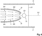
- FIG. 12 shows a view of the top of the lambda probe 23 and the guide vane 24 of the exhaust gas duct section according to FIG figure 2 .
- the perspective of the exhaust duct section was consequently compared to the view in figure 3 rotated by 90° about the central axis 212, so that a view of the top side of the lambda probe 23 and the guide vane 24 is now shown.
- a significant deflection of the exhaust gas 3 is brought about by the described surface 241 .
- the protruding side edges 242 of the guide vane 24, the surface 241 designed in the form of a channel and the ramp-like rise thereof consequently cause the exhaust gas to be deflected in a number of directional axes, so that a particularly pronounced acceleration can take place.
- the guide vane 24 is adjustable so that, among other things, an angle between the in figure 4 surface of the guide vane 24 facing away from the lambda probe 23 and a surface of the exhaust gas duct 21 facing this surface.
- the setting can be specified by an engine control unit 4, with a flow rate measured upstream of the lambda probe 23 using the flow meter 25 serving as the basis for calculation.
- a flow meter could be dispensed with and the flow rate could be determined using a model. That Engine control unit 4 usually models the amount of air, based on which the flow rate of exhaust gas 3 could be calculated.
Landscapes
- Engineering & Computer Science (AREA)
- Chemical & Material Sciences (AREA)
- Combustion & Propulsion (AREA)
- Mechanical Engineering (AREA)
- General Engineering & Computer Science (AREA)
- Chemical Kinetics & Catalysis (AREA)
- Analytical Chemistry (AREA)
- Health & Medical Sciences (AREA)
- Toxicology (AREA)
- Exhaust Silencers (AREA)
Abstract
Description
- Die Erfindung betrifft eine Abgasanlage einer Verbrennungskraftmaschine in einem Fahrzeug, die einen Abgaskanal und ein Abgasnachbehandlungssystem umfasst.
- Der effiziente Betrieb und ein niedriger Schadstoffausstoß von Kraftfahrzeugen unterliegt einer stetigen Analyse und Betrachtung, um den Kraftstoffverbrauch sowie die Abgasemissionen zu reduzieren. Dabei werden sowohl die Rohemissionen durch innermotorische Maßnahmen und intelligente Motorsteuerungskonzepte als auch die in die Umwelt emittierten Emissionen durch verbesserte Abgasnachbehandlungssysteme signifikant reduziert. Ein wichtiger Bestandteil zum Erreichen dieses Ziels ist die Steuerung der Verbrennung in der Verbrennungskraftmaschine des Fahrzeugs. Während der Verbrennung des Luft-Kraftstoff-Gemischs entstehen als Nebenprodukte vorwiegend die Schadstoffe NOx, CO und HC. Die Mengen dieser Schadstoffe, die im Rohabgas enthalten sind, hängen stark vom Brennverfahren und Motorbetrieb ab. Eine Größe, die wesentlichen Einfluss auf die Bildung von Schadstoffen hat, ist die Luftzahl λ. Die korrekte Luftzahl - auch Lambdaverhältnis genannt - ist ein wichtiger Parameter zur Steuerung der Verbrennung und ferner ebenfalls zur Ermöglichung der Abgasreinigung durch Katalysatoren. Darüber hinaus gibt es weitere Kriterien, die die Luftzahl beeinflussen.
- Im Falle eines Benzinmotors liegt definitionsgemäß eine Luftzahl gleich 1 vor, wenn die zugeführte Luftmasse genau der theoretisch erforderlichen Luftmasse zur vollständigen stöchiometrischen Verbrennung des zugeführten Kraftstoffs entspricht. In den meisten Betriebsbereichen werden Motoren mit stöchiometrischem Luft-Kraftstoff-Gemisch (λ = 1) betrieben. In diesem Fall kann beispielsweise ein Dreiwegekatalysator seine bestmögliche Reinigungswirkung entfalten. Eine Luftzahl, die kleiner als 1 ist, wird gewählt, um ein fettes Luft-Kraftstoff-Gemisch zu bilden. Dies erfolgt unter anderem um Bauteile im Abgassystem vor Übertemperatur z. B. bei langen Volllastfahrten zu schützen. Zuletzt ist die Wahl einer Luftzahl größer als 1 möglich. In diesem Bereich herrscht Luftüberschuss und es ergibt sich ein mageres Luft-Kraftstoff-Gemisch. Dieses wird zum Beispiel während des Kaltstarts gewählt, um die HC-Rohemissionen effektiv und schnell mit ausreichend Sauerstoff konvertieren zu können. Dieselmotor arbeiten mit Luftüberschuss. Daher kann der Dreiwegekatalysator nicht zur NOx-Reduktion eingesetzt werden, da im mageren Dieselabgas die HC- und CO-Emissionen am Katalysator bevorzugt dem Restsauerstoff aus dem Abgas und nicht mit NOx reagieren. Die Entfernung der HC- und CO-Emissionen aus dem Dieselabgas erfolgt durch einen Oxidationskatalysator. Die Entfernung der Stickoxide ist grundsätzlich möglich mit einem NOx-Speicherkatalysator oder einem SCR-Katalysator (Selective Catalytic Reduction). Die Entfernung von Rußpartikeln erfolgt mit Hilfe von Rußpartikelfiltern. Zur effizienten Nutzung dieser Maßnahmen wird zeitweise die Luftzahl variiert. Ein NOx-Speicherkatalysator lagert Stickoxide ein und muss daher nach einer bestimmten Zeit bzw. Aufnahmemenge regeneriert werden. Hierfür muss im Abgas Luftmangel herrschen, da als Reduktionsmittel die im Abgas vorhandenen Stoffe CO, H2 und verschiedene Kohlenwasserstoffe dienen.
- Offensichtlich werden die Schadstoffrohemission eines Motors ganz wesentlich durch das Luft-Kraftstoff-Verhältnis (Luftzahl λ) bestimmt. Daher kommt einer genauen und zuverlässigen Erfassung dieser Größe eine herausragende Bedeutung zu. Nur durch genaue Messung und Feststellung der Luftzahl, kann eine für den jeweiligen Betrieb notwendige Gemischbildung eingestellt werden.
- Zu diesem Zweck finden Lambda-Sensoren - auch Lambdasonden genannt - Anwendung, bei denen zwischen Sprungsonden und linearen Sonden (Breitbandsonden) unterschieden wird. Die Sprungsonden ermöglichen eine Regelung des stöchiometrischen Kraftstoff-Luft-Verhältnisses um den mit einer Luftzahl gleich 1, da sie den Übergang von einem zum anderen Bereich feststellen. Breitbandsonden hingegen messen sowohl im fetten als auch mageren Bereich.
- Die Lambdasonde misst den Restsauerstoffgehalt des Abgases und leitet den Wert in Form einer elektrischen Spannung an das Motorsteuergerät. Anhand der Lambdasonden-Spannung erkennt das Steuergerät die Gemisch-Zusammensetzung und kann das Verbrennungsluftverhältnis einstellen.
- Lambdasonden können unterschiedlich aufgebaut sein. Gemein ist allen Ausführungen jedoch, dass sie von dem zu messenden Abgas umspült werden. Zum Schutz empfindlicher Elemente ist am Sondengehäuse abgasseitig ein Schutzrohr angebracht. Dieses schützt das Sensorelement vor Verbrennungsrückständen und Kondenswasser im Abgas. Für den Gaszutritt ist das Schutzrohr mit Löchern versehen. Dementsprechend ist es von großer Bedeutung, dass trotz des Schutzrohrs ausreichend Kontakt der Messelemente mit dem Abgas erfolgen kann.
- Ferner kann für eine effiziente Abgasnachbehandlung wichtig sein, die Stickoxidemissionen zu überwachen. Dies kann durch NOx-Sensoren erfolgen. Diese dienen unter anderem der Regelung der eindosierten Harnstoffmenge in Systemen zur selektiven katalytischen Reduktion (SCR) zur NOx-Reduzierung sowie zur Überwachung (On-Board-Diagnose) der SCR-Komponenten. Der Sensor ermöglicht auch die Überwachung eines NOx-Speicherkatalysators. Auch NOx-Sensoren umfassen ein keramisches Sensorelement, das nach dem amperometrischen Doppelkammerprinzip arbeitet und durch ein Schutzrohr geschützt wird.
-
JP 2016-121652 A -
DE 37 43 295 C1 beschreibt ein Gaslenkblech, das in Strömungsrichtung eines Abgases vor einer Lambda-Sonde angeordnet ist. Dabei ist das Gaslenkblech derartig angeordnet, dass es einen Windschatten für die Lambda-Sonde erzeugt. -
JP 2007-247560 A - Ferner finden Konzepte Anwendung, die zur Gewährleistung ausreichender Strömungsgeschwindigkeiten des Abgases an einer Lambdasonde - insbesondere während des Betriebs in Teillastbereichen - auf einer Verringerung des Strömungsquerschnitts basieren. Dies erfolgt durch eine Einschnürung bzw. Querschnittsreduzierung des Abgaskanals im Bereich einer Lambdasonde. Hierdurch steigt jedoch aufgrund des erhöhten Strömungswiderstands der Abgasgegendruck.
- Der Erfindung liegt nun die Aufgabe zugrunde, eine Abgasanlage für eine Verbrennungskraftmaschine eines Fahrzeugs bereitzustellen, die die genannten Nachteile des Stands der Technik zumindest teilweise überwindet und sicherstellt, dass Gassensoren zur Bestimmung der Gaszusammensetzung, die in der Abgasanlagen Anwendung finden, genaue und zuverlässige Messwerte bereitstellen.
- Diese Aufgabe wird durch eine Abgasanlage mit den Merkmalen des unabhängigen Anspruchs gelöst. Vorteilhafte Ausgestaltungen der Erfindung sind in den Unteransprüchen definiert.
- Die erfindungsgemäße Abgasanlage für eine Verbrennungskraftmaschine eines Fahrzeugs umfasst einen Abgaskanal und ein Abgasnachbehandlungssystem, wobei in dem Abgaskanal mindestens ein Sensor zur Bestimmung der Abgaszusammensetzung angeordnet ist. Weiterhin ist stromaufwärts des Sensors eine Leitschaufel angeordnet, wobei die Leitschaufel ausgebildet ist, die Strömungsgeschwindigkeit des Abgases in einem lokalen Strömungsquerschnitt des Abgaskanals auf Höhe des Sensors zu erhöhen.
- Durch die Erhöhung der Strömungsgeschwindigkeit des Abgases erfährt das Abgas eine Beschleunigung. Insbesondere steigt durch die erfindungsgemäße Abgasanlage die Strömungsgeschwindigkeit des Abgases in einem lokalen Strömungsquerschnitt des Abgaskanals auf Höhe des Sensors. Wie eingangs erläutert, umfassen Sensoren zur Bestimmung der Abgaszusammensetzung, die im Abgasstrom angeordnet sind, Schutzrohre, die die Sensoren vor Verbrennungsrückständen und Wasserschlag schützen sollen. Die Schutzrohre weisen Öffnungen auf, durch die ein Eintritt des Abgases in die Schutzrohre ermöglicht wird. Demzufolge ist eine ausreichend hohe Strömungsgeschwindigkeit des Abgases an dem Schutzrohr der Sensoren wünschenswert. Die Austauschgeschwindigkeit des Gases hängt in hohem Maße von der genannten Strömungsgeschwindigkeit ab. Durch höhere Strömungsgeschwindigkeiten wird ein Eintreten des Abgases in das Messvolumen, das durch das Schutzrohr der Sensoren gebildet wird, erhöht und ersetzt Abgas, das sich bereits für eine gewisse Verweilzeit in dem Volumen befindet. Dieser Austausch wirkt sich auch unmittelbar auf das Messelement der Sensoren aus, da hierdurch die Ansprechzeit der Sensoren verkürzt wird.
- Infolgedessen werden unter anderem direkte Strömungswege sichergestellt und ein verstärkter Impulsaustausch der Gasmoleküle gefördert. Es wird eine schnelle und intensive Vermischung von frisch zuströmendem Abgas mit Abgas, was sich bereits innerhalb des Schutzrohrs des Sensors befindet, ermöglicht. Somit wird eine verbesserte Durchströmung des Schutzrohrs sichergestellt und ferner wird die Verweilzeit von Abgas in dem Schutzrohr verringert. Die Messgenauigkeit und Zuverlässigkeit des Sensors werden dadurch verbessert.
- Demzufolge wird eine ausreichende hohe Strömungsgeschwindigkeit des Abgases, das die Sensoren umströmt und mit diesen in Kontakt ist, sichergestellt. Dabei ist jedoch zu berücksichtigen, dass zu diesem Zweck eine Erhöhung der Strömungsgeschwindigkeit ausschließlich für den beschriebenen, lokalen Bereich um den Sensor ausreichend und ferner auch erwünscht ist. Eine Erhöhung der Strömungsgeschwindigkeit des Abgases in weitergehenden Bereichen des Abgaskanals, in denen das Abgas keinen Einfluss auf die Sensorik und Messgenauigkeit des Sensors nimmt, trägt somit nicht zur Lösung der Aufgabe bei und bewirkt allerdings durch einen Anstieg des Strömungswiderstands einen erhöhten Abgasgegendruck.
- Erfindungsgemäß erfolgt die Anordnung der Leitschaufel stromaufwärts des Sensors. Ferner ist die Leitschaufel ausgebildet, die Strömungsgeschwindigkeit des Abgases in einem lokalen Strömungsquerschnitt des Abgaskanals auf Höhe des Sensors zu erhöhen. Hierdurch wird gewährleistet, dass die Strömungsgeschwindigkeit des Abgases, das den Sensor umströmt und mit diesem in Kontakt steht, ausreichende hohe Werte annimmt. Demzufolge wird erreicht, dass die Sensoren genaue und zuverlässige Messwerte bereitstellen. Durch die Leitschaufel wird die im Abgas, das die Leitschaufel überströmt, enthaltene Enthalpie entweder ganz oder zum Teil in Strömungsenergie umgesetzt. Die Kraft zur Beschleunigung der Fluidteilchen, die Druckgradientkraft und deren Arbeit führt zur Zunahme der kinetischen Energie der Fluidteilchen. Mit anderen Worten erfährt das Abgas durch die Energieumwandlung eine Beschleunigung. Aufgrund der Anordnung der Leitschaufel stromaufwärts des Sensors und seine entsprechende Ausbildung wird somit die Strömungsgeschwindigkeit des Abgases im Abgaskanal auf Höhe des Sensors erhöht. Gleichzeitig wird durch diese lokale Beschränkung der Beeinflussung des Strömungsfelds des Abgases erreicht, dass der Abgasgegendruck nur in geringem Maß beeinflusst wird. Insbesondere erfolgt diese Beeinflussung ausschließlich dort, wo die Abgasströmung Einfluss auf die Messung nimmt. Andere Bereiche bleiben unbeeinflusst.
- In bevorzugter Ausgestaltung der Erfindung ist vorgesehen, dass der Strömungsquerschnitt des Abgaskanals auf Höhe des Sensors konstant ist. In Verbindung mit einer erfindungsgemäßen Leitschaufel können somit im Stand der Technik übliche Einschnürungen im Bereich des Sensors vermieden werden. Neben der effizienten Strömungsbeeinflussung, die sich durch niedrigen Abgasgegendruck auszeichnet, wird hierdurch auch eine platzsparende Lösung ermöglicht, die darüber hinaus konstruktive Anpassungen eines gesamten Abschnitts des Abgaskanals überflüssig machen und daher auch eine wirtschaftlich kostengünstigere Lösung darstellen.
- Gemäß einer bevorzugten Ausführung der Erfindung ist der Sensor zur Bestimmung der Abgaszusammensetzung eine Lambdasonde. In weiterer bevorzugter Ausgestaltung der Erfindung ist vorgesehen, dass der Sensor zur Bestimmung der Abgaszusammensetzung ein NOx-Sensor ist. Beiden Sensortypen ist gemein, dass sie empfindliche Messelemente umfassen, die besonderen Schutz benötigen, der durch Schutzrohre bereitgestellt wird. In Verbindung mit der erfindungsgemäßen Abgasanlage ermöglichen diese Sensoren einen optimierten Betrieb der Verbrennungskraftmaschine, der durch eine genaue und zuverlässige Messung aufgrund der ausreichenden hohen Strömungsgeschwindigkeiten sichergestellt wird. Gleichzeitig sind die Sensoren durch ihren Aufbau stets geschützt und weisen so eine erhöhte Lebensdauer auf, ohne sich negativ auf ihre Genauigkeit auszuwirken.
- In einer vorteilhaften Ausführung der Erfindung ist vorgesehen, dass die Leitschaufel ausgebildet ist, die Strömungsgeschwindigkeit des Abgases auf Höhe des Sensors auf mindestens 5 m/s zu erhöhen, insbesondere auf mindestens 7 m/s, vorzugsweise auf mindestens 10 m/s. Es hat sich gezeigt, dass sich durch Strömungsgeschwindigkeiten ab einem Wert von 5 m/s und oberhalb dieses Werts das Messverhalten der Sensoren im Sinne einer hohen Messgenauigkeit und einem schnellen Ansprechverhalten in besonderem Maße positiv beeinflussen lässt.
- Bevorzugt kann durch Neigen oder Aufrichten der Leitschaufel ein Winkel zwischen der Leitschaufel und dem Abgaskanal variabel verstellt werden. Durch diese Ausführung ist es möglich, das tatsächliche Strömungsverhalten zu berücksichtigen. Eine Anpassung dieses Winkels übt Einfluss auf das Ausmaß der Druckgradientenkraft, die zur Zunahme der kinetischen Energie der Fluidteilchen des Abgases führt, aus. Ein möglicher verstellbarer Winkel ist der Winkel, der zwischen einer in Strömungsrichtung des Abgases überströmten Oberfläche der Leitschaufel, die dem Sensor abgewandt ist, und einer Oberfläche des Abgaskanals, die der überströmten Oberfläche der Leitschaufel ebenfalls abgewandt ist, vorliegt. Somit können verschiedene Anteile der im Abgas enthaltenen Enthalpie in Strömungsenergie umgesetzt werden. Demzufolge kann auch auf Teillastbereiche der Verbrennungskraftmaschine reagiert werden. Somit kann stets in Abhängigkeit eines Betriebspunkts eine ideale Strömungsgeschwindigkeit des Abgases in dem lokalen Strömungsquerschnitt des Abgaskanals auf Höhe des Sensors eingestellt werden.
- In einer weiteren vorteilhaften Ausführung der erfindungsgemäßen Abgasanlage erfolgt die Verstellung des Winkels zwischen der Leitschaufel und dem Abgaskanal in Abhängigkeit einer aktuellen Strömungsgeschwindigkeit des Abgases stromaufwärts des Sensors. Dadurch lässt sich sehr genau und konkret feststellen, ob das Abgas eine ausreichende hohe Strömungsgeschwindigkeit aufweist, damit der Sensor zuverlässige Messwerte feststellt. Liegt eine zu geringe Strömungsgeschwindigkeit vor, lässt sich durch Vergrößern des Winkels eine fortschreitende Beschleunigung des Abgases erzielen, sodass bei Umströmung des Sensors eine geeignete Strömungsgeschwindigkeit des Abgases vorliegt. Umgekehrt lässt sich der Winkel im Fall einer ausreichend hohen bzw. zu hohen Strömungsgeschwindigkeit des Abgases verringern. Demzufolge kann der Druckverlust auf einen Minimalwert, der durch die mindestens notwendige Strömungsgeschwindigkeit des Abgases auf Höhe des Sensors definiert ist, reduziert werden.
- Die Strömungsgeschwindigkeit kann über ein Modell errechnet oder durch ein Durchflussmessgerät gemessen werden. In beiden Fällen ist es möglich, genaue Aussagen zu der Strömungsgeschwindigkeit des Abgases stromaufwärts des Sensors zu treffen.
- Alternativ kann die Verstellung des Winkels zwischen der Leitschaufel und dem Abgaskanal in Abhängigkeit einer Plausibilitätsprüfung bestimmt werden. Dabei wird unter anderem das Lambdasondensignal bzw. die von der Lambdasonde stammenden Messwerte auf Plausibilität überprüft. Werden Werte festgestellt, die Plausibilitätskriterien nicht erfüllen, beispielsweise, da sie aus einem Toleranzbereich eines zu erwartenden Messbereichs fallen, der anhand eines Modells ermittelt wird, kann darauf basierend die Verstellung des Winkels zwischen der Leitschaufel und dem Abgaskanal erfolgen. Bevorzugt kann zusätzlich eine OSC-Messung des Abgaskatalysators erfolgen, anhand derer die Sauerstoffspeicherfähigkeit des Abgaskatalysators geprüft wird. Messwerte der Lambdasonde werden durch die Sauerstoffspeicherfähigkeit des Abgaskatalysators beeinflusst, sodass auch anhand der OSC-Messung eine Aussage zur Plausibilität der Messwerte unternommen werden kann.
- Gemäß einer bevorzugten Ausführung der Erfindung ragen zwei sich in Strömungsrichtung erstreckende Seitenkanten der Leitschaufel in Richtung der Mittelachse vor und eine vom Abgas überströmte Oberfläche der Leitschaufel ist rinnenförmig geformt. Durch eine solche Oberflächenform wird das Anströmprofil des Abgasstroms noch weiter optimiert und die Anströmgeschwindigkeit am Sensor noch weiter erhöht.
- In einer weiteren vorteilhaften Ausführung der erfindungsgemäßen Abgasanlage ist vorgesehen, dass eine sich entlang der Strömungsrichtung erstreckende vom Abgas überströmte Oberfläche der Leitschaufel in Strömungsrichtung des Abgases rampenartig und in Richtung der Mittelachse des Abgaskanals ansteigt. Hierdurch wird eine Leitschaufel mit einer Oberflächenform bereitgestellt, die die Beschleunigung des Abgases noch weiter verbessert.
- Die beiden zuvor genannten Ausführen lassen sich besonders vorteilhaft miteinander kombinieren. Das Strömungsfeld in dem zumeist rohrförmigen Abgaskanal kann hierdurch besonders effektiv beeinflusst werden, da die Strömung in mehreren Dimensionsachsen beeinflusst werden kann, wobei es sich zumindest um eine Achse entlang der Strömungsrichtung des Abgases und zum anderen eine Dimensionsachse senkrecht zu der Strömungsrichtung handelt.
- Bevorzugt ist die Leitschaufel mit dem Abgaskanal form- oder stoffschlüssig verbunden. Dadurch können diverse geeignete Maßnahmen zur Befestigung eingesetzt werden und der Einsatzort der Leitschaufel ist flexibel wählbar. Ferner handelt es sich um bauraumsparende Mechanismen, die sich geeignet nach dem Einsatzort der Sensoren richten können und entkoppelt von anderen Komponenten der Abgasanlage sind.
- Die verschiedenen in dieser Anmeldung genannten Ausführungsformen der Erfindung sind, sofern im Einzelfall nicht anders ausgeführt, mit Vorteil miteinander kombinierbar.
- Die Erfindung wird nachfolgend in Ausführungsbeispielen anhand der zugehörigen Zeichnungen erläutert. Es zeigen:
- Figur 1
- eine Abgasanlage gemäß Stand der Technik in schematischer Ansicht,
- Figur 2
- einen erfindungsgemäßen Systemaufbau gemäß einer Ausführung der Erfindung,
- Figur 3
- eine Seitenansicht eines Abgaskanalabschnitts gemäß der in
Figur 2 dargestellten Ausführung der Erfindung, - Figur 4
- eine Sicht auf die Oberseite der Leitschaufel und der Lambdasonde eines Abgaskanalabschnitts gemäß der in
Figur 2 dargestellten Ausführung der Erfindung. -
Figur 1 zeigt eine Abgasanlage 2' gemäß Stand der Technik, die einer nicht weiter dargestellten Verbrennungskraftmaschine eines ebenfalls nicht gezeigten Fahrzeugs nachgeordnet ist. Die Verbindung mit der Verbrennungskraftmaschine erfolgt über eine Abgaskanal 21. Stromabwärts der Verbrennungskraftmaschine ist ein erster Katalysator 221 angeordnet. Diesem nachgeordnet ist eine Lambdasonde 23, deren Messkopf in den Abgaskanal 21 ragt, wodurch dieser durch das Abgas 3 (dargestellt durch einen Pfeil, der zugleich die Strömungsrichtung des Abgases darstellt) umströmt wird und die Restsauerstoff-Konzentration im Abgas 3 misst. Ebenfalls stromabwärts des ersten Katalysators 221, ist ein zweiter Katalysator 222 angeordnet. Die Katalysatoren 221, 222 dienen der Reduzierung der Abgasemissionen und sind Teil des Abgasnachbehandlungssystems 22. Sämtliche erwähnte Komponenten, die Abgas 3 führen, sind über einen nicht weiter unterteilten Abgaskanal 21 miteinander strömungstechnisch verbunden. - Gemäß dem Stand der Technik weist der Abschnitt 211 des Abgaskanals 21, der zwischen den Katalysatoren 221 und 222 liegt und in dem die Lambdasonde 23 angeordnet ist, einen verringerten Strömungsquerschnitt auf. Dies erfolgt mit dem Ziel, die Strömungsgeschwindigkeit des Abgases 3 in dem eingeschnürten Abschnitt 211 des Abgaskanals 21 zu erhöhen, damit die dort angeordnete Lambdasonde 23 verlässliche Messwerte über die Sauerstoffkonzentration im Abgas 3 bereitstellt. Diese Strömungsbeeinflussung wirkt sich jedoch auf den gesamten Bereich innerhalb dieses Abschnitts 211 des Abgaskanals 21 aus. Demzufolge steigt auch der Strömungswiderstand, was in einem erhöhten Druckverlust und somit in einem steigenden Abgasgegendruck resultiert.
-
Figur 2 zeigt einen erfindungsgemäßen Systemaufbau gemäß einer Ausführung der vorliegenden Erfindung. Dargestellt ist eine Abgasanlage 2, die einer Verbrennungskraftmaschine 1 eines nicht gezeigten Fahrzeugs nachgeordnet ist. Stromabwärts der Verbrennungskraftmaschine 1 ist ein erster Katalysator 221, der in diesem Beispiel als Dreiwegekatalysator ausgestaltet ist, angeordnet. Diesem nachgeordnet ist ein Durchflussmessgerät 25 zur Messung des Abgasmassenstroms. Dem Durchflussmessgerät 25 nachfolgend ist eine Lambdasonde 23 angeordnet, die in den Abgaskanal 21 ragt, wodurch die Lambdasonde 23 durch das Abgas 3 (dargestellt durch einen Pfeil, der zugleich die Strömungsrichtung des Abgases darstellt) umströmt wird und die Restsauerstoff-Konzentration im Abgas 3 misst. Stromab der Lambdasonde 23 ist ein zweiter Katalysator 222 angeordnet, der in diesem Beispiel auch als Dreiwegekatalysator ausgestaltet ist. Das Abgasnachbehandlungssystem 22 umfasst die Katalysatoren, die der Reduzierung der Abgasemissionen dienen. Sämtliche erwähnte Komponenten, die Abgas 3 führen, sind über einen nicht weiter unterteilten Abgaskanal 21 miteinander strömungstechnisch verbunden. - Weiterhin ist stromaufwärts der Lambdasonde 23 eine Leitschaufel 24 angeordnet. Dabei ist die Leitschaufel 24 ausgebildet, die Strömungsgeschwindigkeit des Abgases in einem lokalen Strömungsquerschnitt des Abgaskanals 21 auf Höhe des Sensors zu erhöhen. Dabei bleibt der Strömungsquerschnitt des vom Abgas 3 durchströmten Abgaskanals 21 im Bereich der Lambdasonde 23 konstant. Es erfolgt keine Einschnürung im Bereich der Lambdasonde 23.
- Außerdem umfasst das Fahrzeug einen Bordcomputer bzw. ein Motorsteuergerät 4. Dieses dient unter anderem zur Aufbereitung und Auswertung der Signale, die unter anderem von der Lambdasonde 23 und dem Durchflussmessgerät 25 übermittelt werden.
- Die
Figur 3 zeigt eine Seitenansicht eines Abgaskanalabschnitts des Abgaskanals 21 gemäß der inFigur 2 dargestellten Ausführung der Erfindung. Es handelt sich um den Abgaskanalabschnitt, an dem die Lambdasonde 23 angeordnet ist. Zum Schutz empfindlicher Elemente ist am Sondengehäuse abgasseitig ein Schutzrohr 231 angebracht. Dieses schützt das nicht weiter dargestellte Sensorelement vor festen Verbrennungsrückständen und Kondenswasser im Abgas 3. Für den Gaszutritt verfügt das Schutzrohr 231 über Eintrittslöcher 232. - Stromaufwärts der Lambdasonde 23 ist die Leitschaufel 24 angeordnet, die mit dem Abgaskanal 21 verbunden ist, wobei sie unmittelbar an der Kanalwand befestigt ist. Zwei sich in Strömungsrichtung erstreckende Seitenkanten 242 der Leitschaufel ragen in Richtung der Mittelachse 212 vor. Eine vom Abgas 3 überströmte Oberfläche 241 der Leitschaufel 24 ist dabei rinnenförmig geformt. Mit anderen Worten liegt eine Wölbung der überströmten Oberfläche 241 vor, die bei einer in Strömungsrichtung des Abgases 3 gerichteten Perspektive rinnenförmig ist. Weiterhin steigt die sich entlang der Strömungsrichtung erstreckende vom Abgas 3 überströmte Oberfläche 241 der Leitschaufel 24 in Strömungsrichtung des Abgases 3 rampenartig und in Richtung der Mittelachse 212 des Abgaskanals 21 an. Mit anderen Worten nimmt der Abstand zwischen der Mittelachse 212 und der überströmten Oberfläche 241 in Strömungsrichtung ab. Bevorzugt steigt die Oberfläche 241 dabei derartig an, dass sei eine Wölbung aufweist, die einer konkaven Form nahe kommt.
- Durch die Leitschaufel 24 erfährt das durch Pfeile veranschaulichte Abgas 3 eine Beschleunigung, die sich lokal nur auf die Strömungsgeschwindigkeit des Abgases 3 auf Höhe der Lambdasonde 23 beschränkt. Hierdurch wird ein Zutritt des Abgases durch die Löcher 232 des Schutzrohrs 231 der Lambdasonde 23 in das Messvolumen begünstigt. Dennoch bleibt der Strömungsquerschnitt 211 des Abgaskanals 21 unverändert, sodass der Abgasgegendruck nicht in Folge einer Einschnürung des Abgaskanals 21 steigt. Zusätzlich sind keine konstruktiven und teuren Maßnahmen zur Veränderung der Abgaskanalgeometrie notwendig.
-
Figur 4 zeigt eine Sicht auf die Oberseite der Lambdasonde 23 und der Leitschaufel 24 des Abgaskanalabschnitts gemäßFigur 2 . Die Perspektive auf den Abgaskanalabschnitt wurde folglich gegenüber der Ansicht inFigur 3 um 90° um die Mittelachse 212 rotiert, sodass nun eine Ansicht auf die Oberseite der Lambdasonde 23 und die Leitschaufel 24 dargestellt ist. Durch die beschriebene Oberfläche 241 wird eine wesentliche Umlenkung des Abgases 3 bewirkt. Zusammengenommen verursachen folglich sowohl die vorragenden Seitenkanten 242 der Leitschaufel 24, die rinnenförmige ausgebildete Oberfläche 241 und deren rampenartiger Anstieg eine Umlenkung des Abgases in mehreren Richtungsachsen, sodass eine besonders ausgeprägte Beschleunigung erfolgen kann. - In vorteilhafter Ausgestaltung ist die Leitschaufel 24 verstellbar, sodass unter anderem ein Winkel zwischen der in
Figur 4 der Lambdasonde 23 abgewandten Fläche der Leitschaufel 24 und einer dieser Fläche zugewandten Fläche des Abgaskanals 21 variiert werden kann. Dadurch kann die Stärke der Beschleunigung und somit die Strömungsgeschwindigkeit des Abgases 3 auf Höhe der Lambdasonde angepasst werden. Dies ermöglicht es, auf verschiede Betriebszustände optimal zu reagieren und demzufolge einen minimalen Druckverlust bei gleichzeitig ausreichend hoher Strömungsgeschwindigkeit zuzulassen. Die Einstellung kann durch ein Motorsteuergerät 4 vorgegeben werden, wobei eine mit dem Durchflussmessgerät 25 stromaufwärts der Lambdasonde 23 gemessene Strömungsgeschwindigkeit als Berechnungsgrundlage dient. Alternativ könnte auf ein Durchflussmessgerät verzichtet werden und die Strömungsgeschwindigkeit anhand eines Modells ermittelt werden. Das Motorsteuergerät 4 modelliert üblicherweise die Luftmenge, anhand derer die Strömungsgeschwindigkeit des Abgases 3 berechnet werden könnte. -
- 1
- Verbrennungskraftmaschine
- 2
- Abgasanlage
- 2'
- Abgasanlage gemäß Stand der Technik
- 21
- Abgaskanal
- 211
- Strömungsquerschnitt
- 212
- Mittelachse
- 22
- Abgasnachbehandlungssystem
- 221
- erster Katalysator
- 222
- zweiter Katalysator
- 23
- Lambdasonde
- 231
- Schutzrohr
- 232
- Eintrittslöcher
- 24
- Leitschaufel
- 241
- Oberfläche
- 242
- Kante
- 25
- Durchflussmessgerät
- 3
- Abgas
- 4
- Motorsteuergerät
Claims (10)
- Abgasanlage (2) für eine Verbrennungskraftmaschine (1) eines Fahrzeugs, umfassend einen Abgaskanal (21) und ein Abgasnachbehandlungssystem (22), wobei in dem Abgaskanal (21) mindestens ein Sensor (23) zur Bestimmung der Abgaszusammensetzung angeordnet ist, dadurch gekennzeichnet, dass stromaufwärts des Sensors (23) eine Leitschaufel (24) angeordnet ist, die ausgebildet ist, die Strömungsgeschwindigkeit des Abgases (3) in einem lokalen Strömungsquerschnitt (211) des Abgaskanals (21) auf Höhe des Sensors (23) zu erhöhen.
- Abgasanlage (2) nach Anspruch 1, dadurch gekennzeichnet, dass der Strömungsquerschnitt (211) des Abgaskanals (21) auf Höhe des Sensors (23) konstant ist.
- Abgasanlage (2) nach einem der vorhergehenden Ansprüche, dadurch gekennzeichnet, dass der mindestens eine Sensor (23) zur Bestimmung der Abgaszusammensetzung eine Lambdasonde und/oder ein NOx-Sensor ist.
- Abgasanlage (2) nach einem der vorherigen Ansprüche, dadurch gekennzeichnet, dass die Leitschaufel (24) ausgebildet ist, die Strömungsgeschwindigkeit des Abgases (3) auf Höhe des Sensors (23) auf mindestens 5 m/s zu erhöhen.
- Abgasanlage (2) nach einem der vorherigen Ansprüche, dadurch gekennzeichnet, dass durch Neigen oder Aufrichten der Leitschaufel (24) ein Winkel zwischen der Leitschaufel (24) und dem Abgaskanal (21) variabel verstellbar ist.
- Abgasanlage (2) nach Anspruch 5, dadurch gekennzeichnet, dass die Verstellung des Winkels zwischen der Leitschaufel (24) und dem Abgaskanal (21) in Abhängigkeit einer Strömungsgeschwindigkeit des Abgases (3) auf Höhe des Sensors (23) erfolgt.
- Abgasanlage (2) nach Anspruch 6, dadurch gekennzeichnet, dass die Strömungsgeschwindigkeit über ein Modell errechnet oder durch ein Durchflussmessgerät (25) gemessen wird.
- Abgasanlage (2) nach einem der vorhergehenden Ansprüche, dadurch gekennzeichnet, dass eine sich entlang der Strömungsrichtung erstreckende vom Abgas (3) überströmte Oberfläche (241) der Leitschaufel (24) in Strömungsrichtung des Abgases (3) rampenartig und in Richtung der Mittelachse (212) des Abgaskanals (21) ansteigt.
- Abgasanlage (2) nach einem der vorhergehenden Ansprüche, dadurch gekennzeichnet, dass zwei sich in Strömungsrichtung erstreckende Seitenkanten (242) der Leitschaufel in Richtung der Mittelachse (212) vorragen und eine vom Abgas (3) überströmte Oberfläche (241) der Leitschaufel (24) rinnenförmig geformt ist.
- Abgasanlage (2) nach einem der vorhergehenden Ansprüche, dadurch gekennzeichnet, dass die Leitschaufel (24) mit dem Abgaskanal (21) form- oder stoffschlüssig verbunden ist.
Applications Claiming Priority (1)
| Application Number | Priority Date | Filing Date | Title |
|---|---|---|---|
| DE102021113203.7A DE102021113203A1 (de) | 2021-05-20 | 2021-05-20 | Abgasanlage einer Verbrennungskraftmaschine |
Publications (2)
| Publication Number | Publication Date |
|---|---|
| EP4092256A1 true EP4092256A1 (de) | 2022-11-23 |
| EP4092256B1 EP4092256B1 (de) | 2024-02-28 |
Family
ID=81654909
Family Applications (1)
| Application Number | Title | Priority Date | Filing Date |
|---|---|---|---|
| EP22173546.7A Active EP4092256B1 (de) | 2021-05-20 | 2022-05-16 | Abgasanlage einer verbrennungskraftmaschine |
Country Status (3)
| Country | Link |
|---|---|
| US (1) | US11939898B2 (de) |
| EP (1) | EP4092256B1 (de) |
| DE (1) | DE102021113203A1 (de) |
Citations (8)
| Publication number | Priority date | Publication date | Assignee | Title |
|---|---|---|---|---|
| DE3743295C1 (de) | 1987-12-19 | 1988-07-07 | Daimler Benz Ag | Vorrichtung zur Verlaengerung der Lebensdauer und Verbesserung der Messrepraesentanz einer in dem Abgasstrom eines Verbrennungsmotors eingebauten Lambda-Sonde |
| US20070204597A1 (en) * | 2006-02-27 | 2007-09-06 | Denso Corporation | Exhaust sensor mounting structure |
| JP2007247560A (ja) | 2006-03-16 | 2007-09-27 | Toyota Motor Corp | 内燃機関 |
| DE102013007523A1 (de) * | 2013-05-02 | 2014-11-06 | Daimler Ag | Abgasanlage für einen Kraftwagen |
| JP2016121652A (ja) | 2014-12-25 | 2016-07-07 | 三菱自動車工業株式会社 | 多気筒内燃機関の排気装置 |
| DE102018220131A1 (de) * | 2017-11-24 | 2019-05-29 | Suzuki Motor Corporation | Abgassensor-Anordnungsstruktur und Abgas-Steuersystem |
| DE102018203936A1 (de) * | 2018-03-15 | 2019-09-19 | Audi Ag | Abgasanlage für eine Brennkraftmaschine und entsprechende Brennkraftmaschine |
| EP3767086A1 (de) * | 2019-07-16 | 2021-01-20 | Renault S.A.S. | Sensor zum messen von gaseigenschaften |
Family Cites Families (6)
| Publication number | Priority date | Publication date | Assignee | Title |
|---|---|---|---|---|
| US8418449B2 (en) * | 2008-09-25 | 2013-04-16 | Fev Gmbh | Variable exhaust gas deflector |
| WO2011133155A1 (en) * | 2010-04-22 | 2011-10-27 | International Engine Intellectual Property Company, Llc | Reduction of fouling in after treatment components |
| JP2016151226A (ja) * | 2015-02-18 | 2016-08-22 | 株式会社デンソー | 内燃機関の排気浄化装置 |
| US9932871B2 (en) * | 2015-10-20 | 2018-04-03 | Cummins Emission Solutions Inc. | Variable geometry exhaust conduit |
| JP6701980B2 (ja) * | 2016-06-01 | 2020-05-27 | スズキ株式会社 | 排気ガスセンサの配置構造 |
| GB2558222B (en) * | 2016-12-22 | 2019-05-29 | Perkins Engines Co Ltd | Flow hood assembly |
-
2021
- 2021-05-20 DE DE102021113203.7A patent/DE102021113203A1/de active Pending
-
2022
- 2022-05-16 EP EP22173546.7A patent/EP4092256B1/de active Active
- 2022-05-19 US US17/748,797 patent/US11939898B2/en active Active
Patent Citations (8)
| Publication number | Priority date | Publication date | Assignee | Title |
|---|---|---|---|---|
| DE3743295C1 (de) | 1987-12-19 | 1988-07-07 | Daimler Benz Ag | Vorrichtung zur Verlaengerung der Lebensdauer und Verbesserung der Messrepraesentanz einer in dem Abgasstrom eines Verbrennungsmotors eingebauten Lambda-Sonde |
| US20070204597A1 (en) * | 2006-02-27 | 2007-09-06 | Denso Corporation | Exhaust sensor mounting structure |
| JP2007247560A (ja) | 2006-03-16 | 2007-09-27 | Toyota Motor Corp | 内燃機関 |
| DE102013007523A1 (de) * | 2013-05-02 | 2014-11-06 | Daimler Ag | Abgasanlage für einen Kraftwagen |
| JP2016121652A (ja) | 2014-12-25 | 2016-07-07 | 三菱自動車工業株式会社 | 多気筒内燃機関の排気装置 |
| DE102018220131A1 (de) * | 2017-11-24 | 2019-05-29 | Suzuki Motor Corporation | Abgassensor-Anordnungsstruktur und Abgas-Steuersystem |
| DE102018203936A1 (de) * | 2018-03-15 | 2019-09-19 | Audi Ag | Abgasanlage für eine Brennkraftmaschine und entsprechende Brennkraftmaschine |
| EP3767086A1 (de) * | 2019-07-16 | 2021-01-20 | Renault S.A.S. | Sensor zum messen von gaseigenschaften |
Also Published As
| Publication number | Publication date |
|---|---|
| US20220372906A1 (en) | 2022-11-24 |
| US11939898B2 (en) | 2024-03-26 |
| DE102021113203A1 (de) | 2022-11-24 |
| EP4092256B1 (de) | 2024-02-28 |
Similar Documents
| Publication | Publication Date | Title |
|---|---|---|
| EP1857651B1 (de) | Abgasnachbehandlungseinrichtung für eine Brennkraftmaschine | |
| DE10227838B4 (de) | Katalysatorleistungsabbau-Erfassungsvorrichtung | |
| EP1370759B1 (de) | Verfahren zum betrieb von brennkraftmaschinen | |
| DE102008024177B3 (de) | Verfahren, Vorrichtung und System zur Diagnose eines NOx-Sensors für eine Brennkraftmaschine | |
| DE102012218728B4 (de) | Verfahren zur Überwachung eines Speicherkatalysators einer Brennkraftmaschine | |
| DE19620417C2 (de) | Diagnoseverfahren und Diagnosesystem einer Katalysatoranlage zum Steuern des Abgases bei einem Verbrennungsmotor | |
| EP1767757B1 (de) | Mischglied für eine Abgasanlage | |
| EP2730763B1 (de) | Verfahren und Vorrichtung zum Betrieb eines Sensors zur Bestimmung von Abgaskomponenten, insbesondere für ein Kraftfahrzeug | |
| DE2730770C3 (de) | Ultraschallmeßvorrichtung zur Bestimmung der Strömungsgeschwindigkeit der Luft im Ansaugkanal einer Brennkraftmaschine | |
| DE10332057B4 (de) | Verfahren zur Überprüfung einer Abgasreinigungsanlage | |
| EP1313935B1 (de) | Verfahren zur bestimmung des stickoxidgehalts in sauerstoffhaltigen abgasen von brennkraftmaschinen | |
| DE102009000148A1 (de) | Verfahren zum Überprüfen eines Oxydationskatalysators und Abgasnachbehandlungsanordnung für eine Brennkraftmaschine | |
| EP1818665A2 (de) | Partikelsensor | |
| EP0530655B1 (de) | Verfahren und Vorrichtung zur Regelung eines Otto-Motors und Prüfung eines ihm nachgeschalteten Katalysators | |
| DE102009018525A1 (de) | Abgasrückführsystem für einen Verbrennungsmotor | |
| DE102018203936B4 (de) | Abgasanlage für eine Brennkraftmaschine und entsprechende Brennkraftmaschine | |
| EP4092256B1 (de) | Abgasanlage einer verbrennungskraftmaschine | |
| DE102015200751A1 (de) | Verfahren zur Überwachung einer Abgasnachbehandlungsanlage eines Verbrennungsmotors sowie Steuerungseinrichtung für eine Abgasnachbehandlungsanlage | |
| DE102015200762A1 (de) | Verfahren zur Überwachung einer Abgasnachbehandlungsanlage eines Verbrennungsmotors sowie Steuerungseinrichtung für eine Abgasnachbehandlungsanlage | |
| EP3548719B1 (de) | Verfahren und abgasanlage zur prüfung eines beladungszustands eines partikelfilters | |
| DE102009046391A1 (de) | Verfahren zum Betreiben eines Abgassensors und Abgasanlage mit Abgassensor | |
| DE10233362A1 (de) | Vorrichtung zur Bestimmung der Abgasrückführungsrate einer Brennkraftmaschine | |
| DE10355037B4 (de) | Verfahren zum Optimieren der Abgaswerte einer Brennkraftmaschine | |
| EP1160425B1 (de) | Verfahren und Vorrichtung zur Durchführung einer Regeneration eines NOx-Speicherkatalysators | |
| EP1434049B1 (de) | Verfahren und Vorrichtung zur Überwachung des NOx-Signals eines NOx-Sensors |
Legal Events
| Date | Code | Title | Description |
|---|---|---|---|
| PUAI | Public reference made under article 153(3) epc to a published international application that has entered the european phase |
Free format text: ORIGINAL CODE: 0009012 |
|
| STAA | Information on the status of an ep patent application or granted ep patent |
Free format text: STATUS: THE APPLICATION HAS BEEN PUBLISHED |
|
| AK | Designated contracting states |
Kind code of ref document: A1 Designated state(s): AL AT BE BG CH CY CZ DE DK EE ES FI FR GB GR HR HU IE IS IT LI LT LU LV MC MK MT NL NO PL PT RO RS SE SI SK SM TR |
|
| STAA | Information on the status of an ep patent application or granted ep patent |
Free format text: STATUS: REQUEST FOR EXAMINATION WAS MADE |
|
| 17P | Request for examination filed |
Effective date: 20230523 |
|
| RBV | Designated contracting states (corrected) |
Designated state(s): AL AT BE BG CH CY CZ DE DK EE ES FI FR GB GR HR HU IE IS IT LI LT LU LV MC MK MT NL NO PL PT RO RS SE SI SK SM TR |
|
| STAA | Information on the status of an ep patent application or granted ep patent |
Free format text: STATUS: EXAMINATION IS IN PROGRESS |
|
| 17Q | First examination report despatched |
Effective date: 20230719 |
|
| GRAP | Despatch of communication of intention to grant a patent |
Free format text: ORIGINAL CODE: EPIDOSNIGR1 |
|
| STAA | Information on the status of an ep patent application or granted ep patent |
Free format text: STATUS: GRANT OF PATENT IS INTENDED |
|
| INTG | Intention to grant announced |
Effective date: 20231023 |
|
| GRAS | Grant fee paid |
Free format text: ORIGINAL CODE: EPIDOSNIGR3 |
|
| GRAA | (expected) grant |
Free format text: ORIGINAL CODE: 0009210 |
|
| STAA | Information on the status of an ep patent application or granted ep patent |
Free format text: STATUS: THE PATENT HAS BEEN GRANTED |
|
| AK | Designated contracting states |
Kind code of ref document: B1 Designated state(s): AL AT BE BG CH CY CZ DE DK EE ES FI FR GB GR HR HU IE IS IT LI LT LU LV MC MK MT NL NO PL PT RO RS SE SI SK SM TR |
|
| REG | Reference to a national code |
Ref country code: GB Ref legal event code: FG4D Free format text: NOT ENGLISH |
|
| REG | Reference to a national code |
Ref country code: CH Ref legal event code: EP |
|
| P01 | Opt-out of the competence of the unified patent court (upc) registered |
Effective date: 20240208 |
|
| REG | Reference to a national code |
Ref country code: DE Ref legal event code: R096 Ref document number: 502022000548 Country of ref document: DE |
|
| REG | Reference to a national code |
Ref country code: IE Ref legal event code: FG4D Free format text: LANGUAGE OF EP DOCUMENT: GERMAN |
|
| REG | Reference to a national code |
Ref country code: LT Ref legal event code: MG9D |
|
| PG25 | Lapsed in a contracting state [announced via postgrant information from national office to epo] |
Ref country code: IS Free format text: LAPSE BECAUSE OF FAILURE TO SUBMIT A TRANSLATION OF THE DESCRIPTION OR TO PAY THE FEE WITHIN THE PRESCRIBED TIME-LIMIT Effective date: 20240628 |
|
| REG | Reference to a national code |
Ref country code: NL Ref legal event code: MP Effective date: 20240228 |
|
| PG25 | Lapsed in a contracting state [announced via postgrant information from national office to epo] |
Ref country code: LT Free format text: LAPSE BECAUSE OF FAILURE TO SUBMIT A TRANSLATION OF THE DESCRIPTION OR TO PAY THE FEE WITHIN THE PRESCRIBED TIME-LIMIT Effective date: 20240228 |
|
| PGFP | Annual fee paid to national office [announced via postgrant information from national office to epo] |
Ref country code: DE Payment date: 20240411 Year of fee payment: 5 |
|
| PG25 | Lapsed in a contracting state [announced via postgrant information from national office to epo] |
Ref country code: GR Free format text: LAPSE BECAUSE OF FAILURE TO SUBMIT A TRANSLATION OF THE DESCRIPTION OR TO PAY THE FEE WITHIN THE PRESCRIBED TIME-LIMIT Effective date: 20240529 |
|
| PG25 | Lapsed in a contracting state [announced via postgrant information from national office to epo] |
Ref country code: NL Free format text: LAPSE BECAUSE OF FAILURE TO SUBMIT A TRANSLATION OF THE DESCRIPTION OR TO PAY THE FEE WITHIN THE PRESCRIBED TIME-LIMIT Effective date: 20240228 Ref country code: HR Free format text: LAPSE BECAUSE OF FAILURE TO SUBMIT A TRANSLATION OF THE DESCRIPTION OR TO PAY THE FEE WITHIN THE PRESCRIBED TIME-LIMIT Effective date: 20240228 Ref country code: RS Free format text: LAPSE BECAUSE OF FAILURE TO SUBMIT A TRANSLATION OF THE DESCRIPTION OR TO PAY THE FEE WITHIN THE PRESCRIBED TIME-LIMIT Effective date: 20240528 |
|
| PG25 | Lapsed in a contracting state [announced via postgrant information from national office to epo] |
Ref country code: ES Free format text: LAPSE BECAUSE OF FAILURE TO SUBMIT A TRANSLATION OF THE DESCRIPTION OR TO PAY THE FEE WITHIN THE PRESCRIBED TIME-LIMIT Effective date: 20240228 |
|
| PG25 | Lapsed in a contracting state [announced via postgrant information from national office to epo] |
Ref country code: RS Free format text: LAPSE BECAUSE OF FAILURE TO SUBMIT A TRANSLATION OF THE DESCRIPTION OR TO PAY THE FEE WITHIN THE PRESCRIBED TIME-LIMIT Effective date: 20240528 Ref country code: NO Free format text: LAPSE BECAUSE OF FAILURE TO SUBMIT A TRANSLATION OF THE DESCRIPTION OR TO PAY THE FEE WITHIN THE PRESCRIBED TIME-LIMIT Effective date: 20240528 Ref country code: NL Free format text: LAPSE BECAUSE OF FAILURE TO SUBMIT A TRANSLATION OF THE DESCRIPTION OR TO PAY THE FEE WITHIN THE PRESCRIBED TIME-LIMIT Effective date: 20240228 Ref country code: LT Free format text: LAPSE BECAUSE OF FAILURE TO SUBMIT A TRANSLATION OF THE DESCRIPTION OR TO PAY THE FEE WITHIN THE PRESCRIBED TIME-LIMIT Effective date: 20240228 Ref country code: IS Free format text: LAPSE BECAUSE OF FAILURE TO SUBMIT A TRANSLATION OF THE DESCRIPTION OR TO PAY THE FEE WITHIN THE PRESCRIBED TIME-LIMIT Effective date: 20240628 Ref country code: HR Free format text: LAPSE BECAUSE OF FAILURE TO SUBMIT A TRANSLATION OF THE DESCRIPTION OR TO PAY THE FEE WITHIN THE PRESCRIBED TIME-LIMIT Effective date: 20240228 Ref country code: GR Free format text: LAPSE BECAUSE OF FAILURE TO SUBMIT A TRANSLATION OF THE DESCRIPTION OR TO PAY THE FEE WITHIN THE PRESCRIBED TIME-LIMIT Effective date: 20240529 Ref country code: FI Free format text: LAPSE BECAUSE OF FAILURE TO SUBMIT A TRANSLATION OF THE DESCRIPTION OR TO PAY THE FEE WITHIN THE PRESCRIBED TIME-LIMIT Effective date: 20240228 Ref country code: ES Free format text: LAPSE BECAUSE OF FAILURE TO SUBMIT A TRANSLATION OF THE DESCRIPTION OR TO PAY THE FEE WITHIN THE PRESCRIBED TIME-LIMIT Effective date: 20240228 Ref country code: BG Free format text: LAPSE BECAUSE OF FAILURE TO SUBMIT A TRANSLATION OF THE DESCRIPTION OR TO PAY THE FEE WITHIN THE PRESCRIBED TIME-LIMIT Effective date: 20240228 |
|
| PGFP | Annual fee paid to national office [announced via postgrant information from national office to epo] |
Ref country code: FR Payment date: 20240527 Year of fee payment: 3 |
|
| PG25 | Lapsed in a contracting state [announced via postgrant information from national office to epo] |
Ref country code: PL Free format text: LAPSE BECAUSE OF FAILURE TO SUBMIT A TRANSLATION OF THE DESCRIPTION OR TO PAY THE FEE WITHIN THE PRESCRIBED TIME-LIMIT Effective date: 20240228 Ref country code: PT Free format text: LAPSE BECAUSE OF FAILURE TO SUBMIT A TRANSLATION OF THE DESCRIPTION OR TO PAY THE FEE WITHIN THE PRESCRIBED TIME-LIMIT Effective date: 20240628 |
|
| PG25 | Lapsed in a contracting state [announced via postgrant information from national office to epo] |
Ref country code: SE Free format text: LAPSE BECAUSE OF FAILURE TO SUBMIT A TRANSLATION OF THE DESCRIPTION OR TO PAY THE FEE WITHIN THE PRESCRIBED TIME-LIMIT Effective date: 20240228 Ref country code: PT Free format text: LAPSE BECAUSE OF FAILURE TO SUBMIT A TRANSLATION OF THE DESCRIPTION OR TO PAY THE FEE WITHIN THE PRESCRIBED TIME-LIMIT Effective date: 20240628 Ref country code: PL Free format text: LAPSE BECAUSE OF FAILURE TO SUBMIT A TRANSLATION OF THE DESCRIPTION OR TO PAY THE FEE WITHIN THE PRESCRIBED TIME-LIMIT Effective date: 20240228 Ref country code: LV Free format text: LAPSE BECAUSE OF FAILURE TO SUBMIT A TRANSLATION OF THE DESCRIPTION OR TO PAY THE FEE WITHIN THE PRESCRIBED TIME-LIMIT Effective date: 20240228 |
|
| PG25 | Lapsed in a contracting state [announced via postgrant information from national office to epo] |
Ref country code: DK Free format text: LAPSE BECAUSE OF FAILURE TO SUBMIT A TRANSLATION OF THE DESCRIPTION OR TO PAY THE FEE WITHIN THE PRESCRIBED TIME-LIMIT Effective date: 20240228 |
|
| PG25 | Lapsed in a contracting state [announced via postgrant information from national office to epo] |
Ref country code: SM Free format text: LAPSE BECAUSE OF FAILURE TO SUBMIT A TRANSLATION OF THE DESCRIPTION OR TO PAY THE FEE WITHIN THE PRESCRIBED TIME-LIMIT Effective date: 20240228 |
|
| PG25 | Lapsed in a contracting state [announced via postgrant information from national office to epo] |
Ref country code: EE Free format text: LAPSE BECAUSE OF FAILURE TO SUBMIT A TRANSLATION OF THE DESCRIPTION OR TO PAY THE FEE WITHIN THE PRESCRIBED TIME-LIMIT Effective date: 20240228 Ref country code: CZ Free format text: LAPSE BECAUSE OF FAILURE TO SUBMIT A TRANSLATION OF THE DESCRIPTION OR TO PAY THE FEE WITHIN THE PRESCRIBED TIME-LIMIT Effective date: 20240228 |
|
| PG25 | Lapsed in a contracting state [announced via postgrant information from national office to epo] |
Ref country code: SK Free format text: LAPSE BECAUSE OF FAILURE TO SUBMIT A TRANSLATION OF THE DESCRIPTION OR TO PAY THE FEE WITHIN THE PRESCRIBED TIME-LIMIT Effective date: 20240228 |