EP4092255A1 - Betrieb einer brennkraftmaschine mit einem elektrischen frischgasverdichter und mit einer abgasturbine mit bypassleitung und vtg - Google Patents
Betrieb einer brennkraftmaschine mit einem elektrischen frischgasverdichter und mit einer abgasturbine mit bypassleitung und vtg Download PDFInfo
- Publication number
- EP4092255A1 EP4092255A1 EP22162262.4A EP22162262A EP4092255A1 EP 4092255 A1 EP4092255 A1 EP 4092255A1 EP 22162262 A EP22162262 A EP 22162262A EP 4092255 A1 EP4092255 A1 EP 4092255A1
- Authority
- EP
- European Patent Office
- Prior art keywords
- exhaust gas
- combustion engine
- internal combustion
- fresh
- line
- Prior art date
- Legal status (The legal status is an assumption and is not a legal conclusion. Google has not performed a legal analysis and makes no representation as to the accuracy of the status listed.)
- Granted
Links
Images


Classifications
-
- F—MECHANICAL ENGINEERING; LIGHTING; HEATING; WEAPONS; BLASTING
- F02—COMBUSTION ENGINES; HOT-GAS OR COMBUSTION-PRODUCT ENGINE PLANTS
- F02B—INTERNAL-COMBUSTION PISTON ENGINES; COMBUSTION ENGINES IN GENERAL
- F02B37/00—Engines characterised by provision of pumps driven at least for part of the time by exhaust
- F02B37/04—Engines with exhaust drive and other drive of pumps, e.g. with exhaust-driven pump and mechanically-driven second pump
-
- F—MECHANICAL ENGINEERING; LIGHTING; HEATING; WEAPONS; BLASTING
- F01—MACHINES OR ENGINES IN GENERAL; ENGINE PLANTS IN GENERAL; STEAM ENGINES
- F01N—GAS-FLOW SILENCERS OR EXHAUST APPARATUS FOR MACHINES OR ENGINES IN GENERAL; GAS-FLOW SILENCERS OR EXHAUST APPARATUS FOR INTERNAL-COMBUSTION ENGINES
- F01N3/00—Exhaust or silencing apparatus having means for purifying, rendering innocuous, or otherwise treating exhaust
- F01N3/02—Exhaust or silencing apparatus having means for purifying, rendering innocuous, or otherwise treating exhaust for cooling, or for removing solid constituents of, exhaust
- F01N3/021—Exhaust or silencing apparatus having means for purifying, rendering innocuous, or otherwise treating exhaust for cooling, or for removing solid constituents of, exhaust by means of filters
-
- F—MECHANICAL ENGINEERING; LIGHTING; HEATING; WEAPONS; BLASTING
- F01—MACHINES OR ENGINES IN GENERAL; ENGINE PLANTS IN GENERAL; STEAM ENGINES
- F01N—GAS-FLOW SILENCERS OR EXHAUST APPARATUS FOR MACHINES OR ENGINES IN GENERAL; GAS-FLOW SILENCERS OR EXHAUST APPARATUS FOR INTERNAL-COMBUSTION ENGINES
- F01N3/00—Exhaust or silencing apparatus having means for purifying, rendering innocuous, or otherwise treating exhaust
- F01N3/02—Exhaust or silencing apparatus having means for purifying, rendering innocuous, or otherwise treating exhaust for cooling, or for removing solid constituents of, exhaust
- F01N3/021—Exhaust or silencing apparatus having means for purifying, rendering innocuous, or otherwise treating exhaust for cooling, or for removing solid constituents of, exhaust by means of filters
- F01N3/023—Exhaust or silencing apparatus having means for purifying, rendering innocuous, or otherwise treating exhaust for cooling, or for removing solid constituents of, exhaust by means of filters using means for regenerating the filters, e.g. by burning trapped particles
-
- F—MECHANICAL ENGINEERING; LIGHTING; HEATING; WEAPONS; BLASTING
- F01—MACHINES OR ENGINES IN GENERAL; ENGINE PLANTS IN GENERAL; STEAM ENGINES
- F01N—GAS-FLOW SILENCERS OR EXHAUST APPARATUS FOR MACHINES OR ENGINES IN GENERAL; GAS-FLOW SILENCERS OR EXHAUST APPARATUS FOR INTERNAL-COMBUSTION ENGINES
- F01N3/00—Exhaust or silencing apparatus having means for purifying, rendering innocuous, or otherwise treating exhaust
- F01N3/08—Exhaust or silencing apparatus having means for purifying, rendering innocuous, or otherwise treating exhaust for rendering innocuous
- F01N3/10—Exhaust or silencing apparatus having means for purifying, rendering innocuous, or otherwise treating exhaust for rendering innocuous by thermal or catalytic conversion of noxious components of exhaust
- F01N3/103—Oxidation catalysts for HC and CO only
-
- F—MECHANICAL ENGINEERING; LIGHTING; HEATING; WEAPONS; BLASTING
- F01—MACHINES OR ENGINES IN GENERAL; ENGINE PLANTS IN GENERAL; STEAM ENGINES
- F01N—GAS-FLOW SILENCERS OR EXHAUST APPARATUS FOR MACHINES OR ENGINES IN GENERAL; GAS-FLOW SILENCERS OR EXHAUST APPARATUS FOR INTERNAL-COMBUSTION ENGINES
- F01N3/00—Exhaust or silencing apparatus having means for purifying, rendering innocuous, or otherwise treating exhaust
- F01N3/08—Exhaust or silencing apparatus having means for purifying, rendering innocuous, or otherwise treating exhaust for rendering innocuous
- F01N3/10—Exhaust or silencing apparatus having means for purifying, rendering innocuous, or otherwise treating exhaust for rendering innocuous by thermal or catalytic conversion of noxious components of exhaust
- F01N3/18—Exhaust or silencing apparatus having means for purifying, rendering innocuous, or otherwise treating exhaust for rendering innocuous by thermal or catalytic conversion of noxious components of exhaust characterised by methods of operation; Control
- F01N3/20—Exhaust or silencing apparatus having means for purifying, rendering innocuous, or otherwise treating exhaust for rendering innocuous by thermal or catalytic conversion of noxious components of exhaust characterised by methods of operation; Control specially adapted for catalytic conversion
- F01N3/2006—Periodically heating or cooling catalytic reactors, e.g. at cold starting or overheating
-
- F—MECHANICAL ENGINEERING; LIGHTING; HEATING; WEAPONS; BLASTING
- F01—MACHINES OR ENGINES IN GENERAL; ENGINE PLANTS IN GENERAL; STEAM ENGINES
- F01N—GAS-FLOW SILENCERS OR EXHAUST APPARATUS FOR MACHINES OR ENGINES IN GENERAL; GAS-FLOW SILENCERS OR EXHAUST APPARATUS FOR INTERNAL-COMBUSTION ENGINES
- F01N9/00—Electrical control of exhaust gas treating apparatus
-
- F—MECHANICAL ENGINEERING; LIGHTING; HEATING; WEAPONS; BLASTING
- F02—COMBUSTION ENGINES; HOT-GAS OR COMBUSTION-PRODUCT ENGINE PLANTS
- F02B—INTERNAL-COMBUSTION PISTON ENGINES; COMBUSTION ENGINES IN GENERAL
- F02B37/00—Engines characterised by provision of pumps driven at least for part of the time by exhaust
- F02B37/04—Engines with exhaust drive and other drive of pumps, e.g. with exhaust-driven pump and mechanically-driven second pump
- F02B37/10—Engines with exhaust drive and other drive of pumps, e.g. with exhaust-driven pump and mechanically-driven second pump at least one pump being alternatively or simultaneously driven by exhaust and other drive, e.g. by pressurised fluid from a reservoir or an engine-driven pump
-
- F—MECHANICAL ENGINEERING; LIGHTING; HEATING; WEAPONS; BLASTING
- F02—COMBUSTION ENGINES; HOT-GAS OR COMBUSTION-PRODUCT ENGINE PLANTS
- F02B—INTERNAL-COMBUSTION PISTON ENGINES; COMBUSTION ENGINES IN GENERAL
- F02B37/00—Engines characterised by provision of pumps driven at least for part of the time by exhaust
- F02B37/12—Control of the pumps
- F02B37/18—Control of the pumps by bypassing exhaust from the inlet to the outlet of turbine or to the atmosphere
-
- F—MECHANICAL ENGINEERING; LIGHTING; HEATING; WEAPONS; BLASTING
- F02—COMBUSTION ENGINES; HOT-GAS OR COMBUSTION-PRODUCT ENGINE PLANTS
- F02B—INTERNAL-COMBUSTION PISTON ENGINES; COMBUSTION ENGINES IN GENERAL
- F02B37/00—Engines characterised by provision of pumps driven at least for part of the time by exhaust
- F02B37/12—Control of the pumps
- F02B37/22—Control of the pumps by varying cross-section of exhaust passages or air passages, e.g. by throttling turbine inlets or outlets or by varying effective number of guide conduits
-
- F—MECHANICAL ENGINEERING; LIGHTING; HEATING; WEAPONS; BLASTING
- F02—COMBUSTION ENGINES; HOT-GAS OR COMBUSTION-PRODUCT ENGINE PLANTS
- F02B—INTERNAL-COMBUSTION PISTON ENGINES; COMBUSTION ENGINES IN GENERAL
- F02B37/00—Engines characterised by provision of pumps driven at least for part of the time by exhaust
- F02B37/12—Control of the pumps
- F02B37/24—Control of the pumps by using pumps or turbines with adjustable guide vanes
-
- F—MECHANICAL ENGINEERING; LIGHTING; HEATING; WEAPONS; BLASTING
- F02—COMBUSTION ENGINES; HOT-GAS OR COMBUSTION-PRODUCT ENGINE PLANTS
- F02B—INTERNAL-COMBUSTION PISTON ENGINES; COMBUSTION ENGINES IN GENERAL
- F02B39/00—Component parts, details, or accessories relating to, driven charging or scavenging pumps, not provided for in groups F02B33/00 - F02B37/00
- F02B39/02—Drives of pumps; Varying pump drive gear ratio
- F02B39/08—Non-mechanical drives, e.g. fluid drives having variable gear ratio
- F02B39/10—Non-mechanical drives, e.g. fluid drives having variable gear ratio electric
-
- F—MECHANICAL ENGINEERING; LIGHTING; HEATING; WEAPONS; BLASTING
- F01—MACHINES OR ENGINES IN GENERAL; ENGINE PLANTS IN GENERAL; STEAM ENGINES
- F01N—GAS-FLOW SILENCERS OR EXHAUST APPARATUS FOR MACHINES OR ENGINES IN GENERAL; GAS-FLOW SILENCERS OR EXHAUST APPARATUS FOR INTERNAL-COMBUSTION ENGINES
- F01N2900/00—Details of electrical control or of the monitoring of the exhaust gas treating apparatus
- F01N2900/06—Parameters used for exhaust control or diagnosing
- F01N2900/16—Parameters used for exhaust control or diagnosing said parameters being related to the exhaust apparatus, e.g. particulate filter or catalyst
- F01N2900/1602—Temperature of exhaust gas apparatus
-
- Y—GENERAL TAGGING OF NEW TECHNOLOGICAL DEVELOPMENTS; GENERAL TAGGING OF CROSS-SECTIONAL TECHNOLOGIES SPANNING OVER SEVERAL SECTIONS OF THE IPC; TECHNICAL SUBJECTS COVERED BY FORMER USPC CROSS-REFERENCE ART COLLECTIONS [XRACs] AND DIGESTS
- Y02—TECHNOLOGIES OR APPLICATIONS FOR MITIGATION OR ADAPTATION AGAINST CLIMATE CHANGE
- Y02T—CLIMATE CHANGE MITIGATION TECHNOLOGIES RELATED TO TRANSPORTATION
- Y02T10/00—Road transport of goods or passengers
- Y02T10/10—Internal combustion engine [ICE] based vehicles
- Y02T10/12—Improving ICE efficiencies
Definitions
- the invention relates to a method for operating an internal combustion engine, with an exhaust gas aftertreatment component of the internal combustion engine having an operating temperature that is below a target temperature.
- the exhaust gas aftertreatment components of an exhaust gas aftertreatment device integrated into an exhaust system of the internal combustion engine should always have operating temperatures that are above the respective start temperatures (also called light-off temperatures), from which point they are of sufficient effectiveness with regard to the respective intended exhaust aftertreatment can be assumed.
- the exhaust gas aftertreatment components After a cold start of the internal combustion engine, in which the exhaust gas aftertreatment components have operating temperatures that are well below the respective light-off temperatures, the operating temperatures of at least some of the exhaust gas aftertreatment components should reach the respective light-off temperature as quickly as possible. In order to ensure this, it is known to actively heat individual exhaust gas aftertreatment components.
- heating devices provided for this purpose, which include, for example, electrical heating elements or can be designed as burners.
- internal engine measures can be implemented which aim to generate relatively hot exhaust gas through targeted operation of the internal combustion engine with relatively poor efficiency, so that the exhaust gas can heat up the exhaust gas aftertreatment components relatively quickly.
- the DE 10 2019 200 418 A1 discloses influencing the amount of energy remaining in the exhaust gas downstream of an exhaust gas turbine by means of an electric machine acting on an exhaust gas turbocharger of an internal combustion engine and operating either as an electric motor or as a generator.
- a comparable method is also in the U.S. 2006/0236692 A1 disclosed.
- the DE 10 2018 117 913 A1 describes a method for regenerating a particle filter of an internal combustion engine, with additional air being introduced into the exhaust gas via a blower and additional fuel being introduced into the exhaust system via an injection device Internal combustion engine is injected to increase the temperature of the exhaust gas by oxidizing the fuel with oxygen in the air.
- An exhaust system for a motor vehicle comprises an exhaust manifold, an exhaust gas turbine of an exhaust gas turbocharger connected downstream to the exhaust gas manifold, and an exhaust gas aftertreatment device connected downstream to the exhaust gas turbine, the exhaust gas turbocharger having a bypass channel that can be actuated with the aid of a wastegate valve for charge pressure regulation of the exhaust gas turbocharger. Furthermore, a short-circuit line is provided which is connected to the exhaust manifold and to the exhaust-gas after-treatment device and can be actuated with the aid of a short-circuit valve. Due to the lower heat sink effect of the bypass line compared to the exhaust gas turbocharger, the exhaust aftertreatment device can be heated more quickly to its light-off temperature when exhaust gas is required to be routed via the bypass line and thus does not flow through the exhaust gas turbine.
- the object of the invention is to achieve the fastest possible heating of an exhaust gas aftertreatment component of an internal combustion engine to a setpoint temperature, in particular after a cold start
- a method for operating an internal combustion engine which includes an internal combustion engine, a fresh gas line and an exhaust line.
- At least one fresh-gas compressor is integrated into the fresh-gas line, the fresh-gas compressor being drivable by means of an electric motor.
- At least one exhaust gas turbine which has a variable turbine geometry (VTG), a bypass line with a bypass valve for bypassing the exhaust gas turbine if necessary, and downstream of the exhaust gas turbine and the bypass line, at least one exhaust gas aftertreatment component are integrated into the exhaust line. If, during operation of the internal combustion engine, an operating temperature of the exhaust gas aftertreatment component is below a setpoint temperature, the bypass line is released at least temporarily (by at least partially and preferably completely opening the bypass valve). Furthermore, the fresh gas compressor is then driven by means of the electric motor and the VTG relatively extensively, in particular in at least one 50%, or at least 80%, or at least 90%, or 100% closed position (and held in the appropriate latched position or designated latching range).
- an exhaust gas turbine includes a device by means of which a flow cross section, via which exhaust gas can be guided to a turbine impeller of the exhaust gas turbine, can be changed in terms of effectiveness.
- a flow cross section via which exhaust gas can be guided to a turbine impeller of the exhaust gas turbine, can be changed in terms of effectiveness.
- at least the size of the free flow cross section and preferably also the angle of the flow against blades of the turbine impeller can be variable.
- the more closed the VTG the smaller the free flow cross-section for the flow to the turbine wheel.
- the percentage of the closed position can therefore relate to the ratio of the free flow cross section still available in the respective closed position of the VTG compared to the maximum free flow cross section (when fully open or 0% closed position).
- the percentage specification of the closed position can relate to the strength of an activation of an actuator, by means of which the VTG can be adjusted, this activation preferably taking place by means of pulse width modulation (PWM).
- PWM pulse width modulation
- the aim of the method according to the invention is to heat up the exhaust gas aftertreatment component as quickly as possible until at least the target temperature is reached, in that exhaust gas emitted by the internal combustion engine is routed at least partially and preferably as completely as possible via the bypass line and thus not via the exhaust gas turbine.
- the at least partially and preferably largely or completely closed VTG of the exhaust gas turbine ensures that the resistance for the exhaust gas to flow through the exhaust gas turbine is as high as possible, so that the exhaust gas chooses the path with less resistance via the bypass line as far as possible.
- bypass line can have a significantly smaller thermal mass, so that the cooling of the exhaust gas as it flows through the bypass line can be kept correspondingly low.
- an internal combustion engine operated according to the invention also includes an electric motor for driving the fresh gas compressor, so that sufficient compression of fresh gas that is to be supplied to the internal combustion engine can also be achieved when the exhaust gas is temporarily routed via the bypass line and thus past the exhaust gas turbine becomes.
- the setpoint temperature can preferably be an onset temperature of the exhaust gas aftertreatment component, from which it is assumed that the exhaust gas aftertreatment component is sufficiently effective with regard to the exhaust gas aftertreatment specific to this. According to the invention, it can therefore be provided that the exhaust gas is routed via the bypass line with the aim of heating up the exhaust gas aftertreatment component as quickly as possible when the internal combustion engine is in a warm-up operating phase, which is characterized in that at least one exhaust gas aftertreatment component has an operating temperature that is below the associated light-off temperature.
- the warm-up operating phase can follow a cold start of the internal combustion engine, with a "cold start” being a start-up of the internal combustion engine in which at least the exhaust gas aftertreatment component has an operating temperature which is approximately (i.e.
- a method according to the invention can therefore provide for the exhaust gas to be routed via the bypass line immediately after a cold start of the internal combustion engine with the aim of heating the exhaust gas aftertreatment component as quickly as possible.
- a warm-up operating phase does not always have to follow a cold start or a start-up of the internal combustion engine with an operating temperature of the exhaust gas aftertreatment component that is below the light-off temperature; Rather, a warm-up operating phase can also begin with the internal combustion engine and in particular the internal combustion engine being previously operated in such a way that the previously exceeded light-off temperature is again undershot by a defined extent, as may be the case when the internal combustion engine is idling or overrun for a longer period of time can.
- the setpoint temperature taken into account within the scope of a method according to the invention can also be a regeneration temperature of the exhaust gas aftertreatment component, so that heating of the exhaust gas aftertreatment component, which is supported according to the invention by a flow through with exhaust gas that is still relatively hot, can serve to increase the effectiveness of the exhaust gas aftertreatment component with regard to the for this specific Exhaust aftertreatment, which has decreased as a result of previous operation of the internal combustion engine, to be increased again by thermal regeneration.
- the fresh gas compressor and the exhaust gas turbine of an internal combustion engine operated according to the invention can preferably be coupled mechanically, so that there is a mechanical drive connection between these components, corresponding to the basic structure of an exhaust gas turbocharger.
- a rotation of a turbine impeller of the exhaust gas turbine, which results from exhaust gas flowing through the exhaust gas turbine, can consequently lead directly to a rotation of a compressor impeller of the fresh gas compressor.
- the electric motor assigned to the fresh-gas compressor can then only be provided for a temporary drive of the fresh-gas compressor or the exhaust gas turbocharger, as a result of which this too can be of relatively simple design.
- the VTG is set to the 100% closed position when the bypass line is released in order to supply the exhaust gas aftertreatment component with the hottest possible exhaust gas and when the fresh gas compressor is driven by the electric motor , in order to provide sufficient compression of fresh gas for the operation of the internal combustion engine.
- the fresh gas compressor and the exhaust gas turbine of an internal combustion engine operated according to the invention can also be mechanically decoupled, for example in that the fresh gas compressor can be driven exclusively by means of the electric motor, while the exhaust gas turbine is mechanically coupled to an electric machine that can at least also be operated as a generator and/or to another fresh gas compressor.
- the electrical power to drive the electric motor assigned to the fresh gas compressor can then be provided by the electric machine assigned to the exhaust gas turbine and/or by an electric machine mechanically coupled to the internal combustion engine, with intermediate storage of electrical energy in a storage device that is in a electrical connection between the / the electric machine (s) and the electric motor is involved, can be provided.
- the VTG When operating an internal combustion engine according to the invention with such a mechanical decoupling of the fresh-gas compressor and the exhaust-gas turbine, it can make sense for the VTG not to be set to the 100% closed position or to a position less than 100% closed when the bypass line is released in order to To supply exhaust gas aftertreatment component as hot as possible exhaust gas, and when the fresh gas compressor is driven by the electric motor to provide sufficient compression of fresh gas for the operation of the internal combustion engine.
- This can ensure that the exhaust gas turbine is driven slightly but permanently by a relatively small mass flow of the exhaust gas that flows through it. Disadvantages that could result from a complete standstill of the exhaust gas turbine can be avoided in this way.
- so-called high-pressure exhaust gas recirculation can also be implemented, in which the exhaust gas is branched off from the exhaust line upstream of the exhaust gas turbine and introduced into the fresh gas line downstream of the fresh gas compressor.
- measures may be provided to prevent the fresh gas from flowing over the (high-pressure) exhaust gas recirculation line from the fresh gas line into the exhaust line if the fresh gas compressor is driven by an electric motor as part of the operation of the internal combustion engine according to the invention, so that a correspondingly high boost pressure in the area of a mouth of the Exhaust gas recirculation line into the fresh gas line is present, while in the area of a branching off of the exhaust gas recirculation line from the exhaust line due to the release of the bypass line, there is a relatively low exhaust gas pressure (and therefore a pressure drop across the exhaust gas recirculation line from the fresh gas line to the exhaust line).
- Operation according to the invention of an internal combustion engine with such a (high-pressure) exhaust gas recirculation can therefore possibly require the exhaust gas recirculation line to be temporarily closed by means of a valve integrated into the exhaust gas recirculation line when such a pressure drop is present across the exhaust gas recirculation line.
- the internal combustion engine of an internal combustion engine according to the invention can preferably be a (self-igniting and quality-controlled) diesel engine or a (spark-ignited and quantity-controlled) Otto engine or a combination thereof, i.e. e.g. an internal combustion engine with homogeneous charge compression ignition.
- the internal combustion engine can be operated with both liquid fuel (i.e. diesel or petrol) and gaseous fuel (especially natural gas, LNG or LPG).
- the invention also relates to a motor vehicle, in particular a wheel-based and non-rail-bound motor vehicle (preferably a car or a truck), with an internal combustion engine operated according to the invention or the operation of such a motor vehicle.
- a motor vehicle in particular a wheel-based and non-rail-bound motor vehicle (preferably a car or a truck), with an internal combustion engine operated according to the invention or the operation of such a motor vehicle.
- the internal combustion engine of the internal combustion engine can be provided in particular for the (direct or indirect) provision of the driving power for the motor vehicle.
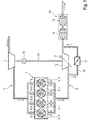
- the 1 shows an internal combustion engine for a motor vehicle that is suitable for operation according to the invention.
- This comprises an internal combustion engine 1, which is designed, for example, in the form of a reciprocating piston engine with four cylinder openings 2 arranged in a row.
- the cylinder openings 2 each delimit a combustion chamber 4 with a movably guided reciprocating piston 3 and a cylinder head (not shown).
- fresh gas is supplied to these combustion chambers 4 via a fresh gas line 5, with the fresh gas being supplied by means of inlet valves 6 , which are assigned to the individual combustion chambers 4, is controlled.
- the fresh gas is exclusively or mainly air that has been sucked in from the environment.
- Exhaust gas that is produced during the combustion of mixture quantities which consists of the fresh gas and fuel injected directly into the combustion chambers 4 via fuel injectors 7, is discharged via an exhaust line 8 of the internal combustion engine, with the exhaust gas being discharged by means of outlet valves 9, which also are assigned to individual combustion chambers 4, is controlled.
- the exhaust gas flows through an exhaust gas after-treatment device 10, which is intended to remove components of the exhaust gas that are regarded as pollutants from the exhaust gas or to convert them into harmless components.
- the quantities of mixture in the combustion chambers 4 can be ignited by means of electrical ignition devices (not shown), which generate ignition sparks (spark plugs), for example, or by self-ignition.
- the internal combustion engine is supercharged, for which purpose a fresh-gas compressor 11 is integrated into the fresh-gas line 5 .
- the fresh gas compressor 11 is part of an exhaust gas turbocharger, which also includes an exhaust gas turbine 12 with variable turbine geometry (VTG) 13 integrated into the exhaust line 9 .
- Exhaust gas that flows through the exhaust gas turbine 12 leads to a rotating drive of a turbine impeller (not shown), which is connected via a shaft 14 in a rotationally driving manner to a compressor impeller (not shown) of the fresh gas compressor 11, so that the result is that the fresh gas compressor 11 is driven by the Exhaust turbine 12 can be done.
- the exhaust gas turbocharger also includes a shaft 14 mechanically coupled electric motor 15, through which, if necessary, the shaft 14 and thus also the compressor impeller of the fresh gas compressor 11 (and the turbine impeller of the exhaust gas turbine 12) can be driven in rotation.
- the exhaust line 8 also includes a bypass line 16 with a bypass valve 17, which branches off from a main line of the exhaust line 8 that integrates the exhaust gas turbine 12 immediately upstream of the exhaust gas turbine 12 and opens back into the main line of the exhaust line 8 immediately downstream of the exhaust gas turbine 12 and thus upstream of the exhaust gas aftertreatment device 10.
- a bypass valve 17 When the bypass valve 17 is open, exhaust gas is routed via the bypass line 16, as a result of which this exhaust gas bypasses the exhaust gas turbine 12 or does not flow through it.
- the exhaust gas aftertreatment device 10 can include, for example, an exhaust gas aftertreatment component in the form of an oxidation catalytic converter 18 and, downstream of the oxidation catalytic converter 18, an exhaust gas aftertreatment component in the form of a particle filter 19.
- the invention provides for the bypass line 16 to be released at least temporarily by at least partially and preferably completely opening the bypass valve 17 and for the VTG 13 to switch to a 100% or as far as possible closed position. As a result, it can be achieved that as far as possible all of the exhaust gas coming from the internal combustion engine 1 is routed via the bypass line 16 and thereby bypasses the exhaust gas turbine 12 .
- the exhaust gas is largely cooled as a result of a flow through the exhaust gas turbine 12, which on the one hand is due to expansion through the exhaust gas turbine 12 and on the other hand to a transfer of thermal energy for heating the also relatively cold exhaust gas turbine 12, which has a relatively large has thermal mass, would be due.
- the bypass line 16 has a relatively small thermal mass, so that a flow through the bypass line 16 leads to only a relatively small cooling of the exhaust gas.
- the exhaust gas therefore arrives at a relatively high temperature in the exhaust gas aftertreatment device 10 and can thus lead to the fastest possible heating of the exhaust gas aftertreatment device 10 or the exhaust gas aftertreatment components comprised by it until at least the respective setpoint temperature is reached.
- the exhaust gas turbine 12 Since the exhaust gas turbine 12 generates little or no drive power for the fresh gas compressor 11 due to the bypass by means of the exhaust gas, during this operation of the internal combustion engine the fresh gas compressor (and due to the mechanical coupling with the exhaust gas turbine 12 also the exhaust gas turbine 12) depending on the requirements of the internal combustion engine 1 driven on fresh gas by means of the electric motor 15. It can thereby be avoided that the bypassing of the exhaust gas turbine 12 with regard to the exhaust gas flow leads to disadvantages in the operating behavior and in particular also with regard to the power output of the internal combustion engine 1 .
- Dashed lines show the behavior of the operation of the same internal combustion engine, in which the exhaust gas is also routed via the bypass line 16 and the fresh gas compressor 11 is driven as required and as required by the electric motor 15, but in which the VTG 13 is in a fully open or closed position 0% closed position is set.
- the operating cycle extends over a period of 900 seconds and is characterized by a variable operation of the internal combustion engine 1, according to the 2 in a greatly fluctuating temperature T 3 of the exhaust gas upstream of the exhaust gas turbine 12 affects.
- the curves of the exhaust gas temperature T 3 for the different internal combustion engines or the different modes of operation of the internal combustion engines are essentially congruent.
- the different modes of operation lead to significantly different mass flows of the exhaust gas through the exhaust gas turbine 12.
- the mass flow of the exhaust gas through the internal combustion engine operated according to the invention is again significantly compared to that in which the bypass line 16 is released but at the same time the VTG 13 is open , is reduced.
- the exhaust gas turbine 12 of the internal combustion engine operated according to the invention heats up significantly more slowly and also to a lesser extent over the course of the operating cycle (cf. 4 ), while the operating temperature T PF of the particle filter 19 of this internal combustion engine rises significantly faster and also to higher values (cf. figure 5 ).
- a disadvantage may be a slightly higher fuel consumption of the internal combustion engine 1, which may be due to the fact that the electrical power required to operate the electric motor 15 driving the fresh-gas compressor 11 is essentially generated by means of a mechanically coupled to the internal combustion engine 1 , generator-driven electric machine (in the 1 not shown) must be generated, which can lead to a higher load during operation of the internal combustion engine 1.
- the exhaust gas in which the exhaust gas is also (partially) routed via the bypass line 16, but in which the VTG 13 is kept open, on the other hand, a higher proportion of the exhaust gas flows through the exhaust gas turbine (cf. 3 ),
- the mechanical coupling to the fresh-gas compressor 11 this covers part of the drive power requirement for the fresh-gas compressor 11, so that correspondingly less drive power has to be provided by the electric motor 15.
Landscapes
- Engineering & Computer Science (AREA)
- Chemical & Material Sciences (AREA)
- Combustion & Propulsion (AREA)
- Mechanical Engineering (AREA)
- General Engineering & Computer Science (AREA)
- Chemical Kinetics & Catalysis (AREA)
- Health & Medical Sciences (AREA)
- Toxicology (AREA)
- Materials Engineering (AREA)
- Supercharger (AREA)
Abstract
Description
- Die Erfindung betrifft ein Verfahren zum Betreiben einer Brennkraftmaschine, wobei eine Abgasnachbehandlungskomponente der Brennkraftmaschine eine Betriebstemperatur aufweist, die unterhalb einer Solltemperatur liegt.
- Um möglichst geringe Schadstoffemissionen einer Brennkraftmaschine zu realisieren, sollten die in einen Abgasstrang der Brennkraftmaschine integrierten Abgasnachbehandlungskomponenten einer Abgasnachbehandlungseinrichtung möglichst stets Betriebstemperaturen aufweisen, die oberhalb der jeweiligen Anspringtemperaturen (auch Light-off-Temperaturen genannt) liegen, ab denen von einer ausreichenden Wirksamkeit hinsichtlich der jeweils vorgesehenen Abgasnachbehandlung ausgegangen werden kann. Nach einem Kaltstart der Brennkraftmaschine, bei dem die Abgasnachbehandlungskomponenten Betriebstemperaturen aufweisen, die deutlich unterhalb der jeweiligen Anspringtemperaturen liegen, sollten die Betriebstemperaturen zumindest einiger der Abgasnachbehandlungskomponenten möglichst schnell die jeweilige Anspringtemperatur erreichen. Um dies zu gewährleisten ist es bekannt, einzelne Abgasnachbehandlungskomponenten aktiv zu beheizen. Dies ist zum einen mittels hierfür vorgesehener Heizvorrichtungen, die beispielsweise elektrische Heizelemente umfassen oder als Brenner ausgebildet sein können, möglich. Weiterhin können sogenannte innermotorische Maßnahmen umgesetzt werden, die darauf abzielen, durch einen gezielten Betrieb des Verbrennungsmotors mit einem relativ schlechten Wirkungsgrad relativ heißes Abgas zu erzeugen, so dass über das Abgas eine relativ schnelle Erwärmung der Abgasnachbehandlungskomponenten erreicht werden kann.
- Die
DE 10 2019 200 418 A1 offenbart, die im Abgas stromabwärts einer Abgasturbine verbleibende Energiemenge mittels einer auf einen Abgasturbolader einer Brennkraftmaschine einwirkenden und wahlweise als Elektromotor oder als Generator arbeitenden Elektromaschine zu beeinflussen. Ein dazu vergleichbares Verfahren ist auch in derUS 2006/0236692 A1 offenbart. - Die
DE 10 2018 117 913 A1 beschreibt ein Verfahren zur Regeneration eines Partikelfilters einer Brennkraftmaschine, wobei über ein Gebläse zusätzliche Luft in das Abgas eingebracht und zusätzlicher Kraftstoff über eine Einspritzvorrichtung in den Abgasstrang der Brennkraftmaschine eingespritzt wird, um durch eine Oxidation des Kraftstoffs mit Sauerstoff der Luft die Temperatur des Abgases zu erhöhen. - Ein Abgassystem für ein Kraftfahrzeug gemäß der
DE 10 2019 102 013 A1 umfasst einen Abgaskrümmer, eine stromabwärts an den Abgaskrümmer angeschlossene Abgasturbine eines Abgasturboladers und eine stromabwärts an der Abgasturbine angeschlossene Abgasnachbehandlungseinrichtung, wobei der Abgasturbolader einen mit Hilfe eines Wastegateventils betätigbaren Bypasskanal zur Ladedruckregelung des Abgasturboladers aufweist. Weiterhin ist eine mit dem Abgaskrümmer und mit der Abgasnachbehandlungseinrichtung verbundene und mit Hilfe eines Kurzschlussventils betätigbare Kurzschlussleitung vorgesehen. Durch den geringeren Wärmesenkeneffekt der Kurzschlussleitung im Vergleich zu dem Abgasturbolader kann die Abgasnachbehandlungseinrichtung schneller auf ihre Anspringtemperatur aufgeheizt werden, wenn Abgas bedarfsweise über die Kurzschlussleitung geführt wird und damit die Abgasturbine nicht durchströmt. - Der Erfindung liegt die Aufgabe zugrunde, ein möglichst schnelles Aufheizen einer Abgasnachbehandlungskomponente einer Brennkraftmaschine auf eine Solltemperatur, insbesondere nach einem Kaltstart, zu erreichen
- Diese Aufgabe wird durch ein Verfahren zum Betreiben einer Brennkraftmaschine gemäß dem Patentanspruch 1 gelöst. Vorteilhafte Ausführungsformen des erfindungsgemäßen Verfahrens sind Gegenstände der weiteren Patentansprüche und ergeben sich aus der nachfolgenden Beschreibung der Erfindung.
- Erfindungsgemäß ist ein Verfahren zum Betreiben einer Brennkraftmaschine, die einen Verbrennungsmotor, einen Frischgasstrang und einen Abgasstrang umfasst, vorgesehen. In den Frischgasstrang ist zumindest ein Frischgasverdichter integriert, wobei der Frischgasverdichter mittels eines Elektromotors antreibbar ist. In den Abgasstrang sind zumindest eine Abgasturbine, die eine variable Turbinengeometrie (VTG) aufweist, eine Bypassleitung mit Bypassventil zur bedarfsweisen Umgehung der Abgasturbine, sowie, stromab der Abgasturbine und der Bypassleitung, zumindest eine Abgasnachbehandlungskomponente integriert. Wenn im Betrieb des Verbrennungsmotors eine Betriebstemperatur der Abgasnachbehandlungskomponente unterhalb einer Solltemperatur liegt, wird zumindest zeitweise die Bypassleitung (durch ein zumindest teilweises und vorzugsweise vollständiges Öffnen des Bypassventils) freigegeben. Weiterhin wird dann der Frischgasverdichter mittels des Elektromotors angetrieben und die VTG relativ weitgehend, insbesondere in eine zu mindestens 50% oder mindestens 80% oder mindestens 90% oder 100% geschlossene Stellung gestellt (und in der entsprechenden Verschlussstellung oder dem vorgesehenen Verschlussbereich gehalten).
- Zur Realisierung einer VTG umfasst eine Abgasturbine eine Vorrichtung, mittels der ein Strömungsquerschnitt, über den Abgas zu einem Turbinenlaufrad der Abgasturbine geführt werden kann, hinsichtlich der Wirksamkeit veränderbar ist. Dazu kann zumindest die Größe des freien Strömungsquerschnitts und vorzugsweise auch der Winkel der Anströmung von Schaufeln des Turbinenlaufrads veränderbar sein. Je weiter geschlossen die VTG ist, desto kleiner ist auch der freie Strömungsquerschnitt zur Anströmung des Turbinenlaufrads. Die prozentuale Angabe der Schließstellung kann sich demnach auf das Verhältnis des in der jeweiligen Schließstellung der VTG noch vorliegenden freien Strömungsquerschnitts im Vergleich zu dem maximalen freien Strömungsquerschnitt (bei vollständig geöffneter beziehungsweise zu 0% geschlossener Stellung) beziehen. Alternativ kann sich die prozentuale Angabe der Schließstellung auf die Stärke einer Ansteuerung eines Aktors, mittels der die VTG verstellt werden kann, beziehen, wobei diese Ansteuerung vorzugsweise mittels Pulsweitenmodulation (PWM) erfolgt.
- Das erfindungsgemäße Verfahren zielt darauf ab, ein möglichst schnelles Aufheizen der Abgasnachbehandlungskomponente bis zumindest zum Erreichen der Solltemperatur zu realisieren, indem von dem Verbrennungsmotor ausgestoßenes Abgas zumindest teilweise und vorzugsweise möglichst vollständig über die Bypassleitung und damit nicht über die Abgasturbine geführt wird. Die zumindest teilweise und vorzugsweise weitestgehend beziehungsweise vollständig geschlossene VTG der Abgasturbine stellt dabei sicher, dass der Widerstand für das Abgas zur Durchströmung der Abgasturbine möglichst hoch ist, so dass das Abgas möglichst weitgehend den widerstandsärmeren Weg über die Bypassleitung wählt. Durch ein Führen von möglichst viel des Abgases über die Bypassleitung kann erreicht werden, dass dieses Abgas bei der Durchströmung der Abgasnachbehandlungskomponente noch eine möglichst hohe Temperatur aufweist. Dabei wird nicht nur eine Abkühlung dieses Abgases, die infolge einer Entspannung in der Abgasturbine auftreten würde, vermieden, sondern auch eine Abkühlung, die daraus resultiert, dass die Abgasturbine, die üblicherweise eine erhebliche thermische Masse aufweist, von dem Abgas erwärmt wird. Im Gegensatz dazu kann die Bypassleitung eine deutlich kleinere thermische Masse aufweisen, so dass die Abkühlung des Abgases beim Durchströmen der Bypassleitung entsprechend gering gehalten werden kann.
- Wenn das Abgas erfindungsgemäß temporär an der Abgasturbine vorbei geleitet wird, wird von der Abgasturbine nur wenig oder keine Antriebsleistung bereitgestellt, die für einen direkten oder indirekten Antrieb des Frischgasverdichters genutzt werden könnte. Vor diesem Hintergrund umfasst eine erfindungsgemäß betriebene Brennkraftmaschine auch einen Elektromotor zum Antreiben des Frischgasverdichters, so dass auch dann eine ausreichende Verdichtung von Frischgas, das dem Verbrennungsmotor zuzuführen ist, erreicht werden kann, wenn das Abgas temporär über die Bypassleitung und damit an der Abgasturbine vorbei geleitet wird.
- Bei der Solltemperatur kann es sich vorzugsweise um eine Anspringtemperatur der Abgasnachbehandlungskomponente handeln, ab der von einer ausreichenden Wirksamkeit der Abgasnachbehandlungskomponente hinsichtlich der für diese spezifischen Abgasnachbehandlung ausgegangen wird. Erfindungsgemäß kann demnach vorgesehen sein, das Abgas über die Bypassleitung mit dem Ziel einer möglichst schnellen Aufheizung der Abgasnachbehandlungskomponente zu führen, wenn sich die Brennkraftmaschine in einer Warmlaufbetriebsphase befindet, die dadurch gekennzeichnet ist, dass zumindest die eine Abgasnachbehandlungskomponente eine Betriebstemperatur aufweist, die unter der dazugehörigen Anspringtemperatur liegt. Die Warmlaufbetriebsphase kann sich dabei an einen Kaltstart der Brennkraftmaschine anschließen, wobei als "Kaltstart" eine Inbetriebnahme der Brennkraftmaschine, bei der zumindest die Abgasnachbehandlungskomponente eine Betriebstemperatur aufweist, die ungefähr (d.h. auch mit einer Abweichung von bis zu 10 K, 20 K oder 30 K) der Umgebungstemperatur entspricht, gilt. Vorzugsweise kann demnach im Rahmen eines erfindungsgemäßen Verfahrens vorgesehen sein, das Abgas unmittelbar im Anschluss an einen Kaltstart der Brennkraftmaschine mit dem Ziel einer möglichst schnellen Aufheizung der Abgasnachbehandlungskomponente über die Bypassleitung zu führen. Eine Warmlaufbetriebsphase muss sich jedoch nicht immer an einen Kaltstart oder an eine Inbetriebnahme der Brennkraftmaschine mit einer unterhalb der Anspringtemperatur liegenden Betriebstemperatur der Abgasnachbehandlungskomponente anschließen; vielmehr kann eine Warmlaufbetriebsphase auch damit beginnen, dass die Brennkraftmaschine und insbesondere der Verbrennungsmotor zuvor derart betrieben wurde, dass die zuvor bereits überschrittene Anspringtemperatur wieder in einem definierten Maße unterschritten wird, wie dies gegebenenfalls bei einem länger andauernden Leerlauf- oder Schubbetrieb des Verbrennungsmotors der Fall sein kann.
- Bei der im Rahmen eines erfindungsgemäßen Verfahrens berücksichtigten Solltemperatur kann es sich auch um eine Regenerationstemperatur der Abgasnachbehandlungskomponente handeln, so dass ein Aufheizen der Abgasnachbehandlungskomponente, das erfindungsgemäß durch eine Durchströmung mit noch relativ heißem Abgas unterstützt wird, dazu dienen kann, die Wirksamkeit der Abgasnachbehandlungskomponente hinsichtlich der für diese spezifischen Abgasnachbehandlung, die infolge eines vorausgegangenen Betriebs der Brennkraftmaschine abgenommen hat, durch eine thermische Regeneration wieder zu erhöhen.
- Der Frischgasverdichter und die Abgasturbine einer erfindungsgemäß betriebenen Brennkraftmaschine können vorzugsweise mechanisch gekoppelt sein, so dass dem grundsätzlichen Aufbau eines Abgasturboladers entsprechend eine mechanische Antriebsverbindung zwischen diesen Komponenten besteht. Eine Rotation eines Turbinenlaufrads der Abgasturbine, die aus einer Durchströmung der Abgasturbine mit Abgas resultiert, kann folglich direkt zu einer Rotation eines Verdichterlaufrads des Frischgasverdichters führen. Dies stellt eine konstruktiv einfache und wirkungsvolle Möglichkeit für einen Antrieb des Frischgasverdichters dar. Der dem Frischgasverdichter zugeordnete Elektromotor kann dann lediglich für einen temporären Antrieb des Frischgasverdichters beziehungsweise des Abgasturboladers vorgesehen sein, wodurch auch dieser konstruktiv relativ einfach ausgestaltet sein kann.
- Bei dem erfindungsgemäßen Betrieb einer Brennkraftmaschine mit einem solchen Abgasturbolader kann vorzugsweise vorgesehen sein, dass die VTG in die 100% geschlossene Stellung gestellt wird, wenn die Bypassleitung freigegeben wird, um der Abgasnachbehandlungskomponente möglichst heißes Abgas zuzuführen, und wenn der Frischgasverdichter mittels des Elektromotors angetrieben wird, um eine ausreichende Verdichtung von Frischgas für den Betrieb des Verbrennungsmotors bereitzustellen. Dadurch kann eine mögliche Sogwirkung, die die Abgasturbine aufgrund des Antriebs des Frischgasverdichters mittels des Elektromotors, der sich durch die mechanische Kopplung auch auf die Abgasturbine überträgt, auf das Abgas aufweist, möglichst gering gehalten und demnach gewährleistet werden, dass möglichst viel des Abgases über die Bypassleitung geführt wird.
- Der Frischgasverdichter und die Abgasturbine einer erfindungsgemäß betriebenen Brennkraftmaschinen können auch mechanisch entkoppelt sein, beispielsweise indem der Frischgasverdichter ausschließlich mittels des Elektromotors antreibbar ist, während die Abgasturbine mit einer zumindest auch als Generator betreibbaren Elektromaschine und/oder mit einem anderen Frischgasverdichter mechanisch gekoppelt ist. Die elektrische Leistung zum Antrieb des dem Frischgasverdichter zugeordneten Elektromotors kann dann durch die der Abgasturbine zugeordnete Elektromaschine und/oder durch eine mit dem Verbrennungsmotor mechanisch gekoppelte Elektromaschine bereitgestellt werden, wobei auch eine Zwischenspeicherung von elektrischer Energie in einer Speichervorrichtung, die in eine elektrische Verbindung zwischen der/den Elektromaschine(n) und dem Elektromotor eingebunden ist, vorgesehen sein kann.
- Bei dem erfindungsgemäßen Betrieb einer Brennkraftmaschine mit einer solchen mechanischen Entkopplung des Frischgasverdichters und der Abgasturbine kann es sinnvoll sein, dass die VTG nicht in die 100% geschlossene beziehungsweise in eine kleiner als 100% geschlossene Stellung gestellt wird, wenn die Bypassleitung freigegeben wird, um der Abgasnachbehandlungskomponente möglichst heißes Abgas zuzuführen, und wenn der Frischgasverdichter mittels des Elektromotors angetrieben wird, um eine ausreichende Verdichtung von Frischgas für den Betrieb des Verbrennungsmotors bereitzustellen. Dadurch kann gewährleistet werden, dass die Abgasturbine geringfügig aber dauerhaft von einem relativ kleinen Massenstrom des Abgases, der diese durchströmt, angetrieben wird. Nachteile, die sich aus einem vollständigen Stillstand der Abgasturbine ergeben könnten, können dadurch vermieden werden. Diese Nachteile können insbesondere eine Unterbrechung einer hydrodynamischen Schmierung der Abgasturbine sein, wodurch bei einer Wiederaufnahme des Betriebs der Abgasturbine kurzzeitig ein relativ großer Verschleiß auftreten kann, der sich nachteilig auf die Lebensdauer der Abgasturbine auswirken kann.
- Zur Erzielung eines möglichst vorteilhaften Schadstoffemissionsverhalten einer erfindungsgemäßen Brennkraftmaschine kann vorzugsweise vorgesehen sein, dass dann, wenn die Bypassleitung freigegeben wird, um der Abgasnachbehandlungskomponente möglichst heißes Abgas zuzuführen, und wenn der Frischgasverdichter mittels des Elektromotors angetrieben wird, um eine ausreichende Verdichtung von Frischgas für den Betrieb des Verbrennungsmotors bereitzustellen, zumindest zeitweise Abgas aus dem Abgasstrang abgezweigt und über einen den Abgasstrang mit dem Frischgasstrang verbindende Abgasrückführleitung in den Frischgasstrang eingeleitet wird. Eine solche Abgasrückführung kann sich insbesondere vorteilhaft hinsichtlich der Stickoxidrohemissionen des Verbrennungsmotors auswirken.
- Weiterhin bevorzugt kann dann vorgesehen sein, dass das Abgas zur Realisierung einer sogenannten Niederdruckabgasrückführung stromab (bezüglich der Strömungsrichtung von Abgas ausgehend von dem Verbrennungsmotor) der Abgasturbine aus dem Abgasstrang abgezweigt und stromauf (bezüglich der Strömungsrichtung von Frischgas in Richtung des Verbrennungsmotors) des Frischgasverdichters in den Frischgasstrang eingeleitet wird. Alternativ dazu ist jedoch auch eine sogenannte Hochdruckabgasrückführung umsetzbar, bei der das Abgas stromauf der Abgasturbine aus dem Abgasstrang abgezweigt und stromab des Frischgasverdichters in den Frischgasstrang eingeleitet wird. In diesem Fall müssten jedoch gegebenenfalls Maßnahmen vorgesehen sein, die verhindern, das Frischgas über die (Hochdruck-)Abgasrückführleitung aus dem Frischgasstrang in den Abgasstrang überströmt, wenn im Rahmen eines erfindungsgemäßen Betriebs der Brennkraftmaschine der Frischgasverdichter elektromotorisch angetrieben wird, so dass ein entsprechend hoher Ladedruck im Bereich einer Mündung der Abgasrückführleitung in den Frischgasstrang vorliegt, während im Bereich einer Abzweigung der Abgasrückführleitung aus dem Abgasstrang infolge der Freigabe der Bypassleitung ein relativ geringer Abgasdruck (und demnach ein Druckgefälle über der Abgasrückführleitung von dem Frischgasstrang zu dem Abgasstrang) vorliegt. Ein erfindungsgemäßer Betrieb einer Brennkraftmaschine mit einer solchen (Hochdruck-)Abgasrückführung kann demnach gegebenenfalls bedingen, dass die Abgasrückführleitung bei dem Vorliegen eines solchen Druckgefälles über der Abgasrückführleitung mittels eines in diese integrierten Ventils temporär verschlossen wird.
- Bei dem Verbrennungsmotor einer erfindungsgemäßen Brennkraftmaschine kann es sich vorzugsweise um einen (selbstzündenden und qualitätsgeregelten) Dieselmotor oder um einen (fremdgezündeten und quantitätsgeregelten) Ottomotor oder um eine Kombination daraus, d.h. z.B. um einen Verbrennungsmotor mit homogener Kompressionszündung, handeln. Der Verbrennungsmotor kann dabei sowohl mit Flüssigkraftstoff (d.h. Diesel oder Benzin) als auch mit einem gasförmigen Kraftstoff (insbesondere Erdgas, LNG oder LPG) betrieben werden.
- Die Erfindung betrifft auch ein Kraftfahrzeug, insbesondere ein radbasiertes und nicht schienengebundenes Kraftfahrzeug (vorzugsweise ein PKW oder ein LKW), mit einer erfindungsgemäß betriebenen Brennkraftmaschine beziehungsweise den Betrieb eines solchen Kraftfahrzeugs. Dabei kann der Verbrennungsmotor der Brennkraftmaschine insbesondere zur (direkten oder indirekten) Bereitstellung der Fahrantriebsleistung für das Kraftfahrzeug vorgesehen sein.
- Die Erfindung wird nachfolgend anhand eines in den Zeichnungen dargestellten Ausführungsbeispiels näher erläutert. In den Zeichnungen zeigt:
- Fig. 1:
- eine erfindungsgemäß betreibbare Brennkraftmaschine in vereinfachter Darstellung;
- Fig. 2:
- die zeitlichen Verläufe der Temperatur T3 des Abgases stromauf einer Abgasturbine bei drei verschiedenartig betriebenen Brennkraftmaschinen während desselben Betriebszyklus;
- Fig. 3:
- entsprechende Verläufe des Massenstroms ṁAT des Abgases durch die jeweilige Abgasturbine bei den drei Brennkraftmaschinen;
- Fig. 4:
- entsprechende Verläufe einer Temperatur TAT der jeweiligen Abgasturbine der drei Brennkraftmaschinen;
- Fig. 5:
- entsprechende Verläufe der Betriebstemperatur TPF eines Partikelfilters der drei Brennkraftmaschinen; und
- Fig. 6:
- entsprechende Verläufe des Kraftstoffverbrauchs FC eine Verbrennungsmotors der drei Brennkraftmaschinen.
- Die
Fig. 1 zeigt eine für einen erfindungsgemäßen Betrieb geeignete Brennkraftmaschine für ein Kraftfahrzeug. Diese umfasst einen Verbrennungsmotor 1, der beispielhaft in Form eines Hubkolbenmotors mit vier in Reihe angeordneten Zylinderöffnungen 2 ausgestaltet ist. Die Zylinderöffnungen 2 begrenzen mit darin beweglich geführten Hubkolben 3 und einem Zylinderkopf (nicht dargestellt) jeweils einen Brennraum 4. Diesen Brennräumen 4 wird im Betrieb des Verbrennungsmotors 1 und damit der Brennkraftmaschine Frischgas über einen Frischgasstrang 5 zugeführt, wobei die Zufuhr des Frischgases mittels Einlassventilen 6, die den einzelnen Brennräumen 4 zugeordnet sind, gesteuert wird. Bei dem Frischgas handelt es sich ausschließlich oder hauptsächlich um Luft, die aus der Umgebung angesaugt wurde. Abgas, das bei der Verbrennung von Gemischmengen entstanden ist, die aus dem Frischgas sowie aus direkt über Kraftstoffinjektoren 7 in die Brennräume 4 eingespritztem Kraftstoff bestehen, wird über einen Abgasstrang 8 der Brennkraftmaschine abgeführt, wobei die Abfuhr des Abgases mittels Auslassventilen 9, die ebenfalls den einzelnen Brennräumen 4 zugeordnet sind, gesteuert wird. Das Abgas durchströmt dabei eine Abgasnachbehandlungseinrichtung 10, die dafür vorgesehen ist, Bestandteile des Abgases, die als Schadstoffe angesehen werden, aus dem Abgas zu entfernen oder in unschädliche Bestandteile umzuwandeln. - Ein Entzünden der Gemischmengen in den Brennräumen 4 kann mittels elektrischer Zündvorrichtungen (nicht dargestellt), die beispielsweise Zündfunken erzeugen (Zündkerzen), oder durch Selbstzündung erfolgen.
- Die Brennkraftmaschine ist aufgeladen ausgestaltet, wozu in den Frischgasstrang 5 ein Frischgasverdichter 11 integriert ist. Der Frischgasverdichter 11 ist Teil eines Abgasturboladers, der weiterhin eine in den Abgasstrang 9 integrierte Abgasturbine 12 mit variabler Turbinengeometrie (VTG) 13 umfasst. Abgas, das die Abgasturbine 12 durchströmt, führt zu einem rotierenden Antrieb eines Turbinenlaufrads (nicht dargestellt), das über eine Welle 14 drehantreibend mit einem Verdichterlaufrad (nicht dargestellt) des Frischgasverdichters 11 verbunden ist, so dass im Ergebnis ein Antrieb des Frischgasverdichters 11 mittels der Abgasturbine 12 erfolgen kann. Der Abgasturbolader umfasst weiterhin einen mit der Welle 14 mechanisch gekoppelten Elektromotor 15, durch den bedarfsweise die Welle 14 und damit auch das Verdichterlaufrad des Frischgasverdichters 11 (sowie das Turbinenlaufrad der Abgasturbine 12) rotierend antreibbar ist.
- Der Abgasstrang 8 umfasst weiterhin eine Bypassleitung 16 mit Bypassventil 17, die unmittelbar stromauf der Abgasturbine 12 aus einem die Abgasturbine12 integrierenden Hauptstrang des Abgasstrangs 8 abzweigt und unmittelbar stromab der Abgasturbine 12 und damit stromauf der Abgasnachbehandlungseinrichtung 10 wieder in den Hauptstrang des Abgasstrangs 8 mündet. Bei geöffnetem Bypassventil 17 wird Abgas über die Bypassleitung 16 geführt, wodurch dieses Abgas die Abgasturbine 12 umgeht beziehungsweise nicht durchströmt.
- Die Abgasnachbehandlungseinrichtung 10 kann beispielsweise eine Abgasnachbehandlungskomponente in Form eines Oxidationskatalysators 18 sowie, stromab des Oxidationskatalysators 18, eine Abgasnachbehandlungskomponente in Form eines Partikelfilters 19 umfassen.
- Sofern zumindest eine dieser Abgasnachbehandlungskomponenten im Betrieb des Verbrennungsmotors 1 eine Betriebstemperatur aufweist, die unterhalb einer definierten Solltemperatur liegt, ist erfindungsgemäß vorgesehen, zumindest temporär die Bypassleitung 16 durch ein zumindest teilweises und vorzugsweise vollständiges Öffnen des Bypassventils 17 freizugeben sowie die VTG 13 in eine 100% beziehungsweise weitestmöglich geschlossene Stellung zu stellen. Dadurch kann erreicht werden, dass möglichst das gesamte von dem Verbrennungsmotor 1 kommende Abgas über die Bypassleitung 16 geführt wird und dadurch die Abgasturbine 12 umgeht. Auf diese Weise kann vermieden werden, dass das Abgas infolge einer Durchströmung der Abgasturbine 12 weitgehend abgekühlt wird, was einerseits auf eine Entspannung durch die Abgasturbine 12 und andererseits auf einen Übergang von Wärmeenergie zum Erwärmen der ebenfalls noch relativ kalten Abgasturbine 12, die eine relativ große thermische Masse aufweist, zurückzuführen wäre. Im Gegensatz dazu weist die Bypassleitung 16 eine relativ kleine thermische Masse auf, so dass ein Durchströmen der Bypassleitung 16 zu einer nur relativ geringen Abkühlung des Abgases führt. Das Abgas gelangt demnach mit einer relativ hohen Temperatur in die Abgasnachbehandlungseinrichtung 10 und kann dadurch zu einer möglichst schnellen Aufheizung der Abgasnachbehandlungseinrichtung 10 beziehungsweise der von dieser umfassten Abgasnachbehandlungskomponenten bis zumindest zum Erreichen der jeweiligen Solltemperatur führen.
- Da die Abgasturbine 12 aufgrund der Umgehung mittels des Abgases kein oder kaum Antriebsleistung für den Frischgasverdichter 11 erzeugt, wird während dieses Betriebs der Brennkraftmaschine der Frischgasverdichter (und aufgrund der mechanischen Kopplung mit der Abgasturbine 12 auch die Abgasturbine 12) in Abhängigkeit von dem Bedarf des Verbrennungsmotors 1 an Frischgas mittels des Elektromotors 15 angetrieben. Dadurch kann vermieden werden, dass die Umgehung der Abgasturbine 12 hinsichtlich des Abgasstroms zu Nachteilen im Betriebsverhalten und insbesondere auch hinsichtlich der Leistungsabgabe des Verbrennungsmotors 1 führt.
- Die
Fig. 2 bis 6 verdeutlichen dieses erfindungsgemäßen Vorgehen und die dabei erzielbaren Vorteile anhand von zeitlichen Verläufen bezüglich der Temperatur T3 des Abgases stromauf der Abgasturbine 12 (vgl.Fig. 2 ), bezüglich des Massenstroms ṁAT des Abgases durch die Abgasturbine 12 (vgl.Fig. 3 ), bezüglich einer Temperatur TAT der Abgasturbine 12 (vgl.Fig. 4 ), bezüglich der Betriebstemperatur TPF des Partikelfilters 19 (vgl.Fig. 5 ) und bezüglich des auf eine Fahrleistung eines die Brennkraftmaschine umfassenden Kraftfahrzeugs bezogenen Kraftstoffverbrauchs FC des Verbrennungsmotors 1 (vgl.Fig. 4 ), jeweils während eines Betriebszyklus der Brennkraftmaschine in einer Warmlaufbetriebsphase, die sich unmittelbar an einen Kaltstart der Brennkraftmaschine bei t = 0 anschließt. - Dabei sind diese Verläufe jeweils mit durgezogener Linienführung für einen erfindungsgemäßen Betrieb einer Brennkraftmaschine gemäß beispielsweise der
Fig. 1 dargestellt, d.h. während des Betriebs wird kontinuierlich Abgas über die Bypassleitung 16 geführt. Weiterhin wird der Frischgasverdichter 11 bedarfsweise und bedarfsgerecht mittels des Elektromotors 15 angetriebenen und die VTG 13 ist in eine zu 95% geschlossene Stellung gestellt. - Mit gestrichelter Linienführung sind dagegen die Verläufe hinsichtlich des Betriebs derselben Brennkraftmaschine dargestellt, bei der das Abgas ebenfalls über die Bypassleitung 16 geführt und der Frischgasverdichter 11 bedarfsweise und bedarfsgerecht mittels des Elektromotors 15 angetrieben wird, bei der jedoch die VTG 13 in eine vollständig geöffnete beziehungsweise zu 0% geschlossene Stellung gestellt ist.
- Und mit gepunkteter Linienführung sind die Verläufe hinsichtlich des Betriebs einer Brennkraftmaschine gezeigt, bei der dem Abgasturbolader kein Elektromotor 15 zugeordnet ist und bei der die für den Betrieb des Verbrennungsmotors 1 gemäß dem Betriebszyklus erforderliche Verdichtung mittels des Frischgasverdichters ausschließlich unter Nutzung von Antriebsleistung erfolgt, die mittels der Abgasturbine 12 bereitgestellt wird, wobei die VTG 13 Abgasturbine 12 in Abhängigkeit von dem Bedarf des Frischgasverdichters 11 an Antriebsleistung verstellt wird. Dabei wird stets das gesamte Abgas über die Abgasturbine 12 geführt. Im Übrigen entspricht diese Brennkraftmaschine der anderen Brennkraftmaschine.
- Der Betriebszyklus erstreckt sich über einen Zeitraum von 900 Sekunden und ist durch einen variablen Betrieb des Verbrennungsmotors 1 gekennzeichnet, der sich gemäß der
Fig. 2 in einer stark schwankenden Temperatur T3 des Abgases stromauf der Abgasturbine 12 auswirkt. Die Verläufe der Abgastemperatur T3 für die verschiedenen Brennkraftmaschinen beziehungsweise die verschiedenen Betriebsweisen die Brennkraftmaschinen sind dabei im Wesentlichen deckungsgleich. - Gemäß der
Fig. 3 führen die unterschiedlichen Betriebsweisen jedoch zu deutlich unterschiedlichen Massenströmen des Abgases durch die Abgasturbine 12. Erkennbar ist, dass der Massenstrom des Abgases durch die erfindungsgemäß betriebene Brennkraftmaschine nochmals deutlich im Vergleich zu derjenigen, bei der die Bypassleitung 16 freigegeben jedoch gleichzeitig auch die VTG 13 geöffnet ist, reduziert ist. Dies führt dazu, dass sich die Abgasturbine 12 der erfindungsgemäß betriebenen Brennkraftmaschine im Verlauf des Betriebszyklus deutlich langsamer und auch in einem geringeren Maße erwärmt (vgl.Fig. 4 ), während die Betriebstemperatur TPF des Partikelfilters 19 dieser Brennkraftmaschine deutlich schneller und auch auf höhere Werte steigt (vgl.Fig. 5 ). Demnach kann durch den erfindungsgemäßen Betrieb der Brennkraftmaschine ein deutlich schnelleres Aufheizen des Partikelfilters 19 beziehungsweise der gesamten Abgasnachbehandlungseinrichtung 10 realisiert werden. Ein Nachteil kann dabei gegebenenfalls in einem geringfügig höheren Kraftstoffverbrauch des Verbrennungsmotors 1 liegen, der darin begründet sein kann, dass die elektrische Leistung, die für den Betrieb des den Frischgasverdichter 11 antreibenden Elektromotors 15 erforderlich ist, im Wesentlichen mittels einer mit dem Verbrennungsmotor 1 mechanisch gekoppelten, generatorisch betriebenen Elektromaschine (in derFig. 1 nicht gezeigt) erzeugt werden muss, was zu einer höheren Last im Betrieb des Verbrennungsmotors 1 führen kann. Bei der Brennkraftmaschine, bei der das Abgas ebenfalls (teilweise) über die Bypassleitung 16 geführt wird, bei der jedoch die VTG 13 geöffnet gehalten ist, strömt dagegen ein höherer Anteil des Abgases durch die Abgasturbine (vgl.Fig. 3 ), wodurch diese infolge der mechanischen Kopplung mit dem Frischgasverdichter 11 einen Teil des Bedarfs an Antriebsleistung für den Frischgasverdichter 11 deckt, so dass entsprechend weniger Antriebsleistung von dem Elektromotor 15 bereitgestellt werden muss. -
- 1
- Verbrennungsmotor
- 2
- Zylinderöffnung
- 3
- Hubkolben
- 4
- Brennraum
- 5
- Frischgasstrang
- 6
- Einlassventil
- 7
- Kraftstoffinjektor
- 8
- Abgasstrang
- 9
- Auslassventil
- 10
- Abgasnachbehandlungseinrichtung
- 11
- Frischgasverdichter
- 12
- Abgasturbine
- 13
- VTG
- 14
- Welle
- 15
- Elektromotor
- 16
- Bypassleitung
- 17
- Bypassventil
- 18
- Oxidationskatalysator
- 19
- Partikelfilter
- T3
- zeitlicher Verlauf der Temperatur des Abgases stromauf der Abgasturbine während eines Betriebszyklus einer Brennkraftmaschine
- ṁAT
- zeitlicher Verlauf des Massenstroms des Abgases durch die Abgasturbine während des Betriebszyklus der Brennkraftmaschine
- TAT
- zeitlicher Verlauf einer Temperatur der Abgasturbine während des Betriebszyklus der Brennkraftmaschine
- TPF
- zeitlicher Verlauf der Betriebstemperatur des Partikelfilters während des Betriebszyklus der Brennkraftmaschine
- FC
- zeitlicher Verlauf des Kraftstoffverbrauchs des Verbrennungsmotors während des Betriebszyklus der Brennkraftmaschine
Claims (10)
- Verfahren zum Betreiben einer Brennkraftmaschine, die• einen Verbrennungsmotor (1),• einen Frischgasstrang (5), in den ein Frischgasverdichter (11) integriert ist, wobei der Frischgasverdichter (11) mittels eines Elektromotors (15) antreibbar ist, und• einen Abgasstrang (8), in den eine Abgasturbine (12), die eine variable Turbinengeometrie (VTG) (13) aufweist, eine Bypassleitung (16) mit Bypassventil (17) zur bedarfsweisen Umgehung der Abgasturbine (12), sowie, stromab der Abgasturbine (12) und der Bypassleitung (16), eine Abgasnachbehandlungskomponente integriert sind,umfasst, dadurch gekennzeichnet, dass dann, wenn im Betrieb des Verbrennungsmotors (1) eine Betriebstemperatur der Abgasnachbehandlungskomponente unterhalb einer Solltemperatur liegt, zumindest zeitweise die Bypassleitung (16) freigegeben, der Frischgasverdichter (11) mittels des Elektromotors (15) angetrieben und die VTG (13) in eine zu mindestens 50% oder mindestens 80% oder mindestens 90% oder 100% geschlossene Stellung gestellt wird.
- Verfahren gemäß Anspruch 1, dadurch gekennzeichnet, dass die Solltemperatur eine Anspringtemperatur der Abgasnachbehandlungskomponente ist.
- Verfahren gemäß Anspruch 1, dadurch gekennzeichnet, dass die Solltemperatur eine Regenerationstemperatur der Abgasnachbehandlungskomponente ist.
- Verfahren gemäß einem der vorhergehenden Ansprüche, dadurch gekennzeichnet, dass unmittelbar nach einem Kaltstart der Brennkraftmaschine der Frischgasverdichter (11) mittels des Elektromotors (15) angetrieben und die VTG (13) in die zu mindestens 50% oder mindestens 80% oder mindestens 90% oder 100% geschlossene Stellung gestellt wird.
- Verfahren gemäß einem der vorhergehenden Ansprüche, dadurch gekennzeichnet, dass der Frischgasverdichter (11) und die Abgasturbine (12) mechanisch gekoppelt sind.
- Verfahren gemäß Anspruch 5, dadurch gekennzeichnet, dass die VTG (13) in die 100% geschlossene Stellung gestellt wird.
- Verfahren gemäß einem der Ansprüche 1 bis 4, dadurch gekennzeichnet, dass der Frischgasverdichter (11) und die Abgasturbine (12) mechanisch entkoppelt sind.
- Verfahren gemäß Anspruch 7, dadurch gekennzeichnet, dass die VTG (13) in eine kleiner als 100% geschlossene Stellung gestellt wird.
- Verfahren gemäß einem der vorhergehenden Ansprüche, dadurch gekennzeichnet, dass dann, wenn die Bypassleitung (16) freigegeben, der Frischgasverdichter (11) mittels des Elektromotors (15) angetrieben und die VTG (13) in die zu mindestens 50% oder mindestens 80% oder mindestens 90% oder 100% geschlossene Stellung gestellt wird, zumindest zweitweise Abgas aus dem Abgasstrang (8) abgezweigt und in den Frischgasstrang (5) eingeleitet wird.
- Verfahren gemäß Anspruch 9, dadurch gekennzeichnet, dass das Abgas stromab der Abgasturbine (12) aus dem Abgasstrang (8) abgezweigt und stromauf des Frischgasverdichters (11) in den Frischgasstrang (5) eingeleitet wird.
Applications Claiming Priority (1)
| Application Number | Priority Date | Filing Date | Title |
|---|---|---|---|
| DE102021205167.7A DE102021205167A1 (de) | 2021-05-20 | 2021-05-20 | Betrieb einer Brennkraftmaschine mit einem elektrischen Frischgasverdichter und mit einer Abgasturbine mit Bypassleitung und VTG |
Publications (2)
| Publication Number | Publication Date |
|---|---|
| EP4092255A1 true EP4092255A1 (de) | 2022-11-23 |
| EP4092255B1 EP4092255B1 (de) | 2024-06-26 |
Family
ID=80780923
Family Applications (1)
| Application Number | Title | Priority Date | Filing Date |
|---|---|---|---|
| EP22162262.4A Active EP4092255B1 (de) | 2021-05-20 | 2022-03-15 | Betrieb einer brennkraftmaschine mit einem elektrischen frischgasverdichter und mit einer abgasturbine mit bypassleitung und vtg |
Country Status (3)
| Country | Link |
|---|---|
| US (1) | US20220372908A1 (de) |
| EP (1) | EP4092255B1 (de) |
| DE (1) | DE102021205167A1 (de) |
Citations (7)
| Publication number | Priority date | Publication date | Assignee | Title |
|---|---|---|---|---|
| US20060236692A1 (en) | 2005-04-25 | 2006-10-26 | Kolavennu Soumitri N | Control of exhaust temperature for after-treatment process in an e-turbo system |
| DE102018117913A1 (de) | 2017-07-26 | 2019-01-31 | Ford Global Technologies, Llc | Verfahren und System zur Partikelfilterregeneration |
| US20200131981A1 (en) * | 2018-10-26 | 2020-04-30 | BMTS Technology GmbH & Co. KG | Method for operating a combustion engine system |
| US20200224614A1 (en) * | 2019-01-16 | 2020-07-16 | Ford Global Technologies, Llc | Method and system for emissions reduction |
| DE102019200418A1 (de) | 2019-01-16 | 2020-07-16 | Ford Global Technologies, Llc | Verfahren zur Beeinflussung der Temperatur eines Abgases, Hybridmotoranordnung und Hybridelektrokraftfahrzeug |
| DE102019102013A1 (de) | 2019-01-28 | 2020-07-30 | Dr. Ing. H.C. F. Porsche Aktiengesellschaft | Abgassystem und Verfahren zum Betrieb eines Abgassystems |
| DE102020006467A1 (de) * | 2020-10-21 | 2020-12-10 | FEV Group GmbH | Abgasstranganordnung für einen Verbrennungsmotor zur Steigerung der Effizienz einer Abgasnachbehandlungskomponente bei einem Kaltstart des Verbrennungsmotors |
Family Cites Families (4)
| Publication number | Priority date | Publication date | Assignee | Title |
|---|---|---|---|---|
| DE2326206A1 (de) * | 1973-05-23 | 1974-12-12 | Daimler Benz Ag | Brennkraftmaschine, insbesondere luftverdichtende einspritzbrennkraftmaschine |
| JP2009257301A (ja) * | 2008-03-19 | 2009-11-05 | Ihi Corp | 排気ガス浄化触媒の暖機方法及びシステム |
| US10920661B2 (en) | 2017-09-06 | 2021-02-16 | Superturbo Technologies, Inc. | Turbine bypass for engine with driven turbocharger |
| US10975790B2 (en) | 2019-08-26 | 2021-04-13 | Ford Global Technologies, Llc | Systems and methods for controlling boost during an engine cold start |
-
2021
- 2021-05-20 DE DE102021205167.7A patent/DE102021205167A1/de active Pending
-
2022
- 2022-03-15 EP EP22162262.4A patent/EP4092255B1/de active Active
- 2022-05-19 US US17/748,951 patent/US20220372908A1/en not_active Abandoned
Patent Citations (7)
| Publication number | Priority date | Publication date | Assignee | Title |
|---|---|---|---|---|
| US20060236692A1 (en) | 2005-04-25 | 2006-10-26 | Kolavennu Soumitri N | Control of exhaust temperature for after-treatment process in an e-turbo system |
| DE102018117913A1 (de) | 2017-07-26 | 2019-01-31 | Ford Global Technologies, Llc | Verfahren und System zur Partikelfilterregeneration |
| US20200131981A1 (en) * | 2018-10-26 | 2020-04-30 | BMTS Technology GmbH & Co. KG | Method for operating a combustion engine system |
| US20200224614A1 (en) * | 2019-01-16 | 2020-07-16 | Ford Global Technologies, Llc | Method and system for emissions reduction |
| DE102019200418A1 (de) | 2019-01-16 | 2020-07-16 | Ford Global Technologies, Llc | Verfahren zur Beeinflussung der Temperatur eines Abgases, Hybridmotoranordnung und Hybridelektrokraftfahrzeug |
| DE102019102013A1 (de) | 2019-01-28 | 2020-07-30 | Dr. Ing. H.C. F. Porsche Aktiengesellschaft | Abgassystem und Verfahren zum Betrieb eines Abgassystems |
| DE102020006467A1 (de) * | 2020-10-21 | 2020-12-10 | FEV Group GmbH | Abgasstranganordnung für einen Verbrennungsmotor zur Steigerung der Effizienz einer Abgasnachbehandlungskomponente bei einem Kaltstart des Verbrennungsmotors |
Also Published As
| Publication number | Publication date |
|---|---|
| EP4092255B1 (de) | 2024-06-26 |
| US20220372908A1 (en) | 2022-11-24 |
| DE102021205167A1 (de) | 2022-11-24 |
Similar Documents
| Publication | Publication Date | Title |
|---|---|---|
| DE102011084782B4 (de) | Verfahren zum Betreiben einer aufgeladenen Brennkraftmaschine mit Abgasrückführung | |
| DE102019115180A1 (de) | System und verfahren zum beschleunigen der motorerwärmung | |
| DE102010027220A1 (de) | Verfahren zum Starten einer Brennkraftmaschine | |
| DE102021111152A1 (de) | Motoranordnung und Verfahren | |
| DE10203025B4 (de) | Vorrichtung und Verfahren zur Steuerung eines Verbrennungsmotors | |
| DE102007058964A1 (de) | System und Verfahren zur Aufladung einer Brennkraftmaschine | |
| DE102021205170A1 (de) | Brennkraftmaschine mit einer stromab eines Frischgasverdichters abzweigenden Sekundärluftleitung | |
| EP3056705A1 (de) | Turbo-aufgeladene brennkraftmaschine mit einem fremdgezündeten verbrennungsmotor und verfahren zum betreiben einer derartigen brennkraftmaschine | |
| EP3947943B1 (de) | Verfahren zum betreiben eines verbrennungsmotors sowie verbrennungsmotor | |
| EP4092255B1 (de) | Betrieb einer brennkraftmaschine mit einem elektrischen frischgasverdichter und mit einer abgasturbine mit bypassleitung und vtg | |
| DE102020213702A1 (de) | Brennkraftmaschine mit Heizvorrichtung im Abgasstrang | |
| EP4063638B1 (de) | Erwärmung einer abgasrückführleitung während eines schubbetriebs eines verbrennungsmotors | |
| DE102018130799B4 (de) | Verbrennungsmotor und Verfahren zum Betreiben eines Verbrennungsmotors | |
| WO2012113425A1 (de) | Abgasturboladeranordnung | |
| DE102012011086A1 (de) | Verbrennungskraftmaschine für einen Kraftwagen sowie Verfahren zum Betreiben einer solchen Verbrennungskraftmaschine | |
| DE102019006494B4 (de) | Abgasanlage für eine Verbrennungskraftmaschine eines Kraftfahrzeugs, Antriebseinrichtung für ein Kraftfahrzeug sowie Kraftfahrzeug | |
| DE102018117124B4 (de) | Verbrennungsmotor und Verfahren zur Abgasnachbehandlung eines solchen Verbrennungsmotors | |
| DE102012200012A1 (de) | Aufgeladene Brennkraftmaschine und Verfahren zum Betreiben einer derartigen Brennkraftmaschine | |
| DE102021213060B4 (de) | Brennkraftmaschine mit elektrisch beheizbarer Abgasnachbehandlungsvorrichtung und Verfahren zum Betreiben einer Brennkraftmaschine | |
| DE102006029370A1 (de) | Verfahren zur Steigerung des Ladedruckaufbaus bei aufgeladenen Verbrennungskraftmaschinen | |
| EP4083399B1 (de) | Brennkraftmaschine mit elektrischer abgasturbine und abgasnachbehandlungseinrichtung stromauf der abgasturbine | |
| DE102021107092A1 (de) | Brennkraftmaschine mit Abgasnachbehandlungskomponente, Heizvorrichtung und Gasfördervorrichtung | |
| DE102019113741A1 (de) | Brennkraftmaschine mit variabler Auslassventilbetätigung und mit elektromotorischer oder mechanischer Aufladung | |
| EP4060168B1 (de) | Abgastemperaturabhängige regeneration eines partikelfilters mittels einer heizvorrichtung | |
| DE102021102240A1 (de) | Abgasnachbehandlung bei einer Brennkraftmaschine |
Legal Events
| Date | Code | Title | Description |
|---|---|---|---|
| PUAI | Public reference made under article 153(3) epc to a published international application that has entered the european phase |
Free format text: ORIGINAL CODE: 0009012 |
|
| STAA | Information on the status of an ep patent application or granted ep patent |
Free format text: STATUS: THE APPLICATION HAS BEEN PUBLISHED |
|
| AK | Designated contracting states |
Kind code of ref document: A1 Designated state(s): AL AT BE BG CH CY CZ DE DK EE ES FI FR GB GR HR HU IE IS IT LI LT LU LV MC MK MT NL NO PL PT RO RS SE SI SK SM TR |
|
| STAA | Information on the status of an ep patent application or granted ep patent |
Free format text: STATUS: REQUEST FOR EXAMINATION WAS MADE |
|
| 17P | Request for examination filed |
Effective date: 20230523 |
|
| RBV | Designated contracting states (corrected) |
Designated state(s): AL AT BE BG CH CY CZ DE DK EE ES FI FR GB GR HR HU IE IS IT LI LT LU LV MC MK MT NL NO PL PT RO RS SE SI SK SM TR |
|
| GRAP | Despatch of communication of intention to grant a patent |
Free format text: ORIGINAL CODE: EPIDOSNIGR1 |
|
| RIC1 | Information provided on ipc code assigned before grant |
Ipc: F02B 39/10 20060101ALI20231221BHEP Ipc: F02B 37/24 20060101ALI20231221BHEP Ipc: F02B 37/18 20060101ALI20231221BHEP Ipc: F02B 37/10 20060101ALI20231221BHEP Ipc: F01N 9/00 20060101ALI20231221BHEP Ipc: F01N 3/10 20060101ALI20231221BHEP Ipc: F01N 3/021 20060101AFI20231221BHEP |
|
| STAA | Information on the status of an ep patent application or granted ep patent |
Free format text: STATUS: GRANT OF PATENT IS INTENDED |
|
| INTG | Intention to grant announced |
Effective date: 20240125 |
|
| GRAS | Grant fee paid |
Free format text: ORIGINAL CODE: EPIDOSNIGR3 |
|
| GRAA | (expected) grant |
Free format text: ORIGINAL CODE: 0009210 |
|
| STAA | Information on the status of an ep patent application or granted ep patent |
Free format text: STATUS: THE PATENT HAS BEEN GRANTED |
|
| P01 | Opt-out of the competence of the unified patent court (upc) registered |
Effective date: 20240513 |
|
| AK | Designated contracting states |
Kind code of ref document: B1 Designated state(s): AL AT BE BG CH CY CZ DE DK EE ES FI FR GB GR HR HU IE IS IT LI LT LU LV MC MK MT NL NO PL PT RO RS SE SI SK SM TR |
|
| REG | Reference to a national code |
Ref country code: GB Ref legal event code: FG4D Free format text: NOT ENGLISH |
|
| REG | Reference to a national code |
Ref country code: CH Ref legal event code: EP |
|
| REG | Reference to a national code |
Ref country code: DE Ref legal event code: R096 Ref document number: 502022001099 Country of ref document: DE |
|
| PG25 | Lapsed in a contracting state [announced via postgrant information from national office to epo] |
Ref country code: BG Free format text: LAPSE BECAUSE OF FAILURE TO SUBMIT A TRANSLATION OF THE DESCRIPTION OR TO PAY THE FEE WITHIN THE PRESCRIBED TIME-LIMIT Effective date: 20240626 |
|
| PG25 | Lapsed in a contracting state [announced via postgrant information from national office to epo] |
Ref country code: FI Free format text: LAPSE BECAUSE OF FAILURE TO SUBMIT A TRANSLATION OF THE DESCRIPTION OR TO PAY THE FEE WITHIN THE PRESCRIBED TIME-LIMIT Effective date: 20240626 Ref country code: HR Free format text: LAPSE BECAUSE OF FAILURE TO SUBMIT A TRANSLATION OF THE DESCRIPTION OR TO PAY THE FEE WITHIN THE PRESCRIBED TIME-LIMIT Effective date: 20240626 |
|
| REG | Reference to a national code |
Ref country code: LT Ref legal event code: MG9D |
|
| PG25 | Lapsed in a contracting state [announced via postgrant information from national office to epo] |
Ref country code: GR Free format text: LAPSE BECAUSE OF FAILURE TO SUBMIT A TRANSLATION OF THE DESCRIPTION OR TO PAY THE FEE WITHIN THE PRESCRIBED TIME-LIMIT Effective date: 20240927 |
|
| PG25 | Lapsed in a contracting state [announced via postgrant information from national office to epo] |
Ref country code: LV Free format text: LAPSE BECAUSE OF FAILURE TO SUBMIT A TRANSLATION OF THE DESCRIPTION OR TO PAY THE FEE WITHIN THE PRESCRIBED TIME-LIMIT Effective date: 20240626 |
|
| REG | Reference to a national code |
Ref country code: NL Ref legal event code: MP Effective date: 20240626 |
|
| PG25 | Lapsed in a contracting state [announced via postgrant information from national office to epo] |
Ref country code: NO Free format text: LAPSE BECAUSE OF FAILURE TO SUBMIT A TRANSLATION OF THE DESCRIPTION OR TO PAY THE FEE WITHIN THE PRESCRIBED TIME-LIMIT Effective date: 20240926 Ref country code: LV Free format text: LAPSE BECAUSE OF FAILURE TO SUBMIT A TRANSLATION OF THE DESCRIPTION OR TO PAY THE FEE WITHIN THE PRESCRIBED TIME-LIMIT Effective date: 20240626 Ref country code: HR Free format text: LAPSE BECAUSE OF FAILURE TO SUBMIT A TRANSLATION OF THE DESCRIPTION OR TO PAY THE FEE WITHIN THE PRESCRIBED TIME-LIMIT Effective date: 20240626 Ref country code: GR Free format text: LAPSE BECAUSE OF FAILURE TO SUBMIT A TRANSLATION OF THE DESCRIPTION OR TO PAY THE FEE WITHIN THE PRESCRIBED TIME-LIMIT Effective date: 20240927 Ref country code: FI Free format text: LAPSE BECAUSE OF FAILURE TO SUBMIT A TRANSLATION OF THE DESCRIPTION OR TO PAY THE FEE WITHIN THE PRESCRIBED TIME-LIMIT Effective date: 20240626 Ref country code: BG Free format text: LAPSE BECAUSE OF FAILURE TO SUBMIT A TRANSLATION OF THE DESCRIPTION OR TO PAY THE FEE WITHIN THE PRESCRIBED TIME-LIMIT Effective date: 20240626 Ref country code: RS Free format text: LAPSE BECAUSE OF FAILURE TO SUBMIT A TRANSLATION OF THE DESCRIPTION OR TO PAY THE FEE WITHIN THE PRESCRIBED TIME-LIMIT Effective date: 20240926 |
|
| PG25 | Lapsed in a contracting state [announced via postgrant information from national office to epo] |
Ref country code: NL Free format text: LAPSE BECAUSE OF FAILURE TO SUBMIT A TRANSLATION OF THE DESCRIPTION OR TO PAY THE FEE WITHIN THE PRESCRIBED TIME-LIMIT Effective date: 20240626 |
|
| PG25 | Lapsed in a contracting state [announced via postgrant information from national office to epo] |
Ref country code: NL Free format text: LAPSE BECAUSE OF FAILURE TO SUBMIT A TRANSLATION OF THE DESCRIPTION OR TO PAY THE FEE WITHIN THE PRESCRIBED TIME-LIMIT Effective date: 20240626 |
|
| PG25 | Lapsed in a contracting state [announced via postgrant information from national office to epo] |
Ref country code: PT Free format text: LAPSE BECAUSE OF FAILURE TO SUBMIT A TRANSLATION OF THE DESCRIPTION OR TO PAY THE FEE WITHIN THE PRESCRIBED TIME-LIMIT Effective date: 20241028 |
|
| PG25 | Lapsed in a contracting state [announced via postgrant information from national office to epo] |
Ref country code: PT Free format text: LAPSE BECAUSE OF FAILURE TO SUBMIT A TRANSLATION OF THE DESCRIPTION OR TO PAY THE FEE WITHIN THE PRESCRIBED TIME-LIMIT Effective date: 20241028 |
|
| PG25 | Lapsed in a contracting state [announced via postgrant information from national office to epo] |
Ref country code: PL Free format text: LAPSE BECAUSE OF FAILURE TO SUBMIT A TRANSLATION OF THE DESCRIPTION OR TO PAY THE FEE WITHIN THE PRESCRIBED TIME-LIMIT Effective date: 20240626 |
|
| PG25 | Lapsed in a contracting state [announced via postgrant information from national office to epo] |
Ref country code: EE Free format text: LAPSE BECAUSE OF FAILURE TO SUBMIT A TRANSLATION OF THE DESCRIPTION OR TO PAY THE FEE WITHIN THE PRESCRIBED TIME-LIMIT Effective date: 20240626 |
|
| PG25 | Lapsed in a contracting state [announced via postgrant information from national office to epo] |
Ref country code: IS Free format text: LAPSE BECAUSE OF FAILURE TO SUBMIT A TRANSLATION OF THE DESCRIPTION OR TO PAY THE FEE WITHIN THE PRESCRIBED TIME-LIMIT Effective date: 20241026 |
|
| PG25 | Lapsed in a contracting state [announced via postgrant information from national office to epo] |
Ref country code: CZ Free format text: LAPSE BECAUSE OF FAILURE TO SUBMIT A TRANSLATION OF THE DESCRIPTION OR TO PAY THE FEE WITHIN THE PRESCRIBED TIME-LIMIT Effective date: 20240626 |
|
| PG25 | Lapsed in a contracting state [announced via postgrant information from national office to epo] |
Ref country code: RO Free format text: LAPSE BECAUSE OF FAILURE TO SUBMIT A TRANSLATION OF THE DESCRIPTION OR TO PAY THE FEE WITHIN THE PRESCRIBED TIME-LIMIT Effective date: 20240626 Ref country code: SK Free format text: LAPSE BECAUSE OF FAILURE TO SUBMIT A TRANSLATION OF THE DESCRIPTION OR TO PAY THE FEE WITHIN THE PRESCRIBED TIME-LIMIT Effective date: 20240626 |
|
| PG25 | Lapsed in a contracting state [announced via postgrant information from national office to epo] |
Ref country code: SM Free format text: LAPSE BECAUSE OF FAILURE TO SUBMIT A TRANSLATION OF THE DESCRIPTION OR TO PAY THE FEE WITHIN THE PRESCRIBED TIME-LIMIT Effective date: 20240626 Ref country code: ES Free format text: LAPSE BECAUSE OF FAILURE TO SUBMIT A TRANSLATION OF THE DESCRIPTION OR TO PAY THE FEE WITHIN THE PRESCRIBED TIME-LIMIT Effective date: 20240626 |
|
| PG25 | Lapsed in a contracting state [announced via postgrant information from national office to epo] |
Ref country code: SM Free format text: LAPSE BECAUSE OF FAILURE TO SUBMIT A TRANSLATION OF THE DESCRIPTION OR TO PAY THE FEE WITHIN THE PRESCRIBED TIME-LIMIT Effective date: 20240626 Ref country code: SK Free format text: LAPSE BECAUSE OF FAILURE TO SUBMIT A TRANSLATION OF THE DESCRIPTION OR TO PAY THE FEE WITHIN THE PRESCRIBED TIME-LIMIT Effective date: 20240626 Ref country code: RO Free format text: LAPSE BECAUSE OF FAILURE TO SUBMIT A TRANSLATION OF THE DESCRIPTION OR TO PAY THE FEE WITHIN THE PRESCRIBED TIME-LIMIT Effective date: 20240626 Ref country code: PL Free format text: LAPSE BECAUSE OF FAILURE TO SUBMIT A TRANSLATION OF THE DESCRIPTION OR TO PAY THE FEE WITHIN THE PRESCRIBED TIME-LIMIT Effective date: 20240626 Ref country code: IS Free format text: LAPSE BECAUSE OF FAILURE TO SUBMIT A TRANSLATION OF THE DESCRIPTION OR TO PAY THE FEE WITHIN THE PRESCRIBED TIME-LIMIT Effective date: 20241026 Ref country code: ES Free format text: LAPSE BECAUSE OF FAILURE TO SUBMIT A TRANSLATION OF THE DESCRIPTION OR TO PAY THE FEE WITHIN THE PRESCRIBED TIME-LIMIT Effective date: 20240626 Ref country code: EE Free format text: LAPSE BECAUSE OF FAILURE TO SUBMIT A TRANSLATION OF THE DESCRIPTION OR TO PAY THE FEE WITHIN THE PRESCRIBED TIME-LIMIT Effective date: 20240626 Ref country code: CZ Free format text: LAPSE BECAUSE OF FAILURE TO SUBMIT A TRANSLATION OF THE DESCRIPTION OR TO PAY THE FEE WITHIN THE PRESCRIBED TIME-LIMIT Effective date: 20240626 |
|
| PG25 | Lapsed in a contracting state [announced via postgrant information from national office to epo] |
Ref country code: IT Free format text: LAPSE BECAUSE OF FAILURE TO SUBMIT A TRANSLATION OF THE DESCRIPTION OR TO PAY THE FEE WITHIN THE PRESCRIBED TIME-LIMIT Effective date: 20240626 |
|
| REG | Reference to a national code |
Ref country code: DE Ref legal event code: R097 Ref document number: 502022001099 Country of ref document: DE |
|
| PG25 | Lapsed in a contracting state [announced via postgrant information from national office to epo] |
Ref country code: DK Free format text: LAPSE BECAUSE OF FAILURE TO SUBMIT A TRANSLATION OF THE DESCRIPTION OR TO PAY THE FEE WITHIN THE PRESCRIBED TIME-LIMIT Effective date: 20240626 |
|
| PLBE | No opposition filed within time limit |
Free format text: ORIGINAL CODE: 0009261 |
|
| STAA | Information on the status of an ep patent application or granted ep patent |
Free format text: STATUS: NO OPPOSITION FILED WITHIN TIME LIMIT |
|
| 26N | No opposition filed |
Effective date: 20250327 |
|
| PG25 | Lapsed in a contracting state [announced via postgrant information from national office to epo] |
Ref country code: SE Free format text: LAPSE BECAUSE OF FAILURE TO SUBMIT A TRANSLATION OF THE DESCRIPTION OR TO PAY THE FEE WITHIN THE PRESCRIBED TIME-LIMIT Effective date: 20240626 |
|
| PG25 | Lapsed in a contracting state [announced via postgrant information from national office to epo] |
Ref country code: MC Free format text: LAPSE BECAUSE OF FAILURE TO SUBMIT A TRANSLATION OF THE DESCRIPTION OR TO PAY THE FEE WITHIN THE PRESCRIBED TIME-LIMIT Effective date: 20240626 |
|
| REG | Reference to a national code |
Ref country code: CH Ref legal event code: H13 Free format text: ST27 STATUS EVENT CODE: U-0-0-H10-H13 (AS PROVIDED BY THE NATIONAL OFFICE) Effective date: 20251023 |
|
| PG25 | Lapsed in a contracting state [announced via postgrant information from national office to epo] |
Ref country code: LU Free format text: LAPSE BECAUSE OF NON-PAYMENT OF DUE FEES Effective date: 20250315 |
|
| REG | Reference to a national code |
Ref country code: BE Ref legal event code: MM Effective date: 20250331 |
|
| PG25 | Lapsed in a contracting state [announced via postgrant information from national office to epo] |
Ref country code: FR Free format text: LAPSE BECAUSE OF NON-PAYMENT OF DUE FEES Effective date: 20250331 |
|
| PG25 | Lapsed in a contracting state [announced via postgrant information from national office to epo] |
Ref country code: BE Free format text: LAPSE BECAUSE OF NON-PAYMENT OF DUE FEES Effective date: 20250331 |
|
| PG25 | Lapsed in a contracting state [announced via postgrant information from national office to epo] |
Ref country code: CH Free format text: LAPSE BECAUSE OF NON-PAYMENT OF DUE FEES Effective date: 20250331 |
|
| PG25 | Lapsed in a contracting state [announced via postgrant information from national office to epo] |
Ref country code: IE Free format text: LAPSE BECAUSE OF NON-PAYMENT OF DUE FEES Effective date: 20250315 |
|
| PGFP | Annual fee paid to national office [announced via postgrant information from national office to epo] |
Ref country code: DE Payment date: 20260331 Year of fee payment: 5 |
|
| PGFP | Annual fee paid to national office [announced via postgrant information from national office to epo] |
Ref country code: AT Payment date: 20260301 Year of fee payment: 5 |