EP4092245A2 - Spiralkolbenanordnung - Google Patents
Spiralkolbenanordnung Download PDFInfo
- Publication number
- EP4092245A2 EP4092245A2 EP22184965.6A EP22184965A EP4092245A2 EP 4092245 A2 EP4092245 A2 EP 4092245A2 EP 22184965 A EP22184965 A EP 22184965A EP 4092245 A2 EP4092245 A2 EP 4092245A2
- Authority
- EP
- European Patent Office
- Prior art keywords
- piston
- cylinder
- load nut
- feature
- inner member
- Prior art date
- Legal status (The legal status is an assumption and is not a legal conclusion. Google has not performed a legal analysis and makes no representation as to the accuracy of the status listed.)
- Granted
Links
Images


Classifications
-
- E—FIXED CONSTRUCTIONS
- E21—EARTH OR ROCK DRILLING; MINING
- E21B—EARTH OR ROCK DRILLING; OBTAINING OIL, GAS, WATER, SOLUBLE OR MELTABLE MATERIALS OR A SLURRY OF MINERALS FROM WELLS
- E21B33/00—Sealing or packing boreholes or wells
- E21B33/02—Surface sealing or packing
- E21B33/03—Well heads; Setting-up thereof
- E21B33/04—Casing heads; Suspending casings or tubings in well heads
- E21B33/0415—Casing heads; Suspending casings or tubings in well heads rotating or floating support for tubing or casing hanger
-
- B—PERFORMING OPERATIONS; TRANSPORTING
- B66—HOISTING; LIFTING; HAULING
- B66F—HOISTING, LIFTING, HAULING OR PUSHING, NOT OTHERWISE PROVIDED FOR, e.g. DEVICES WHICH APPLY A LIFTING OR PUSHING FORCE DIRECTLY TO THE SURFACE OF A LOAD
- B66F3/00—Devices, e.g. jacks, adapted for uninterrupted lifting of loads
- B66F3/24—Devices, e.g. jacks, adapted for uninterrupted lifting of loads fluid-pressure operated
- B66F3/25—Constructional features
-
- E—FIXED CONSTRUCTIONS
- E21—EARTH OR ROCK DRILLING; MINING
- E21B—EARTH OR ROCK DRILLING; OBTAINING OIL, GAS, WATER, SOLUBLE OR MELTABLE MATERIALS OR A SLURRY OF MINERALS FROM WELLS
- E21B33/00—Sealing or packing boreholes or wells
- E21B33/02—Surface sealing or packing
- E21B33/03—Well heads; Setting-up thereof
- E21B33/035—Well heads; Setting-up thereof specially adapted for underwater installations
- E21B33/0355—Control systems, e.g. hydraulic, pneumatic, electric, acoustic, for submerged well heads
-
- E—FIXED CONSTRUCTIONS
- E21—EARTH OR ROCK DRILLING; MINING
- E21B—EARTH OR ROCK DRILLING; OBTAINING OIL, GAS, WATER, SOLUBLE OR MELTABLE MATERIALS OR A SLURRY OF MINERALS FROM WELLS
- E21B33/00—Sealing or packing boreholes or wells
- E21B33/02—Surface sealing or packing
- E21B33/03—Well heads; Setting-up thereof
- E21B33/04—Casing heads; Suspending casings or tubings in well heads
- E21B33/043—Casing heads; Suspending casings or tubings in well heads specially adapted for underwater well heads
Definitions
- the present disclosure is directed to a coiled piston assembly per se, and to a coiled piston assembly for use in a wellhead system which includes a tubing hanger that is landed and locked in a wellhead positioned at the upper end of a well bore.
- the coiled piston assembly is mounted on the tubing hanger and is used to adjust the vertical position of the tubing hanger load shoulder so that the vertical distance between the load shoulder and the tubing hanger lockdown mechanism is the same as the vertical distance between the seat on which the load shoulder is landed and the locking profile in the bore of the wellhead which the lockdown mechanism is configured to engage.
- the present disclosure is also directed to a coiled piston assembly for use in securing an inner member to an outer member which surrounds at least a portion of the inner member.
- Subsea hydrocarbon production systems typically include a wellhead which is positioned at the upper end of a well bore.
- the wellhead comprises a central bore within which a number of casing hangers are landed.
- Each casing hanger is connected to the top of a corresponding one of a number of concentric, successively smaller casing strings which extend into the well bore, with the uppermost casing hanger being connected to the innermost casing string.
- a tubing string is run into the well bore.
- the top of the tubing string is connected to a tubing hanger having a downward facing circumferential load shoulder which lands on a seat formed at the top of the uppermost casing hanger.
- the load shoulder is formed on a load nut which is threadedly connected to the tubing hanger body.
- the tubing hanger is usually secured to the wellhead using a lockdown mechanism, such as a lock ring or a number of locking dogs, both of which comprise a number of axially spaced, circumferential locking ridges.
- the locking dogs are supported on the tubing hanger body and are expandable radially outwardly into a locking profile formed in the bore of the wellhead, such as a number of axially spaced, circumferential locking grooves, each of which is configured to receive a corresponding locking ridge.
- the vertical distance between the load shoulder and the locking dogs must be the same as the vertical distance between the seat and the locking profile, which is commonly referred to as the wellhead space-out.
- the term "the same as” should be interpreted to mean that the vertical distance between the seat and the locking profile is such that the locking ridges can fully engage their corresponding locking grooves.
- the vertical distance between the load shoulder and the locking dogs can be adjusted by rotating the load nut relative to the tubing hanger body.
- the load nut can be rotated until the vertical distance between the load shoulder and the locking dogs is the same as the wellhead space-out.
- a lead impression tool (LIT) is sometimes used to measure the wellhead space-out.
- the LIT is lowered on a drill string and landed on the seat.
- the LIT is then hydraulically actuated to press typically three circumferentially spaced lead impression pads into the locking profile.
- the LIT is retrieved to the surface and mounted on a storage/test stand, which is then manually adjusted to match the lead impression tool.
- the tubing hanger is then mounted on the storage/test stand and the load nut is adjusted until the vertical distance between the load shoulder and the locking dogs is the same as the wellhead space-out.
- the LIT provides a useful means for determining the wellhead space-out
- the time required to run and retrieve the LIT can be relatively long, especially in deep water.
- setting the tubing hanger on the storage/test stand and adjusting the load nut can be a time consuming process and is dependent on human interpretation.
- a tubing hanger assembly which includes a body which comprises an annular outer surface; a lockdown feature which is located on the body; a load nut which is threadedly connected to the body, the load nut comprising a downward facing load shoulder; and a piston assembly.
- This piston assembly includes an elongated cylinder which is positioned circumferentially around the outer surface of the body axially adjacent the load nut, the cylinder comprising a first cylinder end which is connected to the body and an open second cylinder end; an elongated piston which is slidably received in the cylinder, the piston comprising a first piston end which is oriented toward the first cylinder end and a second piston end which is configured to extend through the second cylinder end and engage the load nut such that extension of the piston causes the load nut to rotate relative to the body; and a seal which is positioned between the piston and the cylinder to thereby define a piston chamber between the first cylinder end and the first piston end, the piston chamber being connectable to a source of fluid pressure.
- the piston rotates the load nut to thereby move the load nut axially relative to the body. In this manner, an axial distance between the load shoulder and the lockdown feature is adjustable.
- the piston and the cylinder may each comprise a helical configuration.
- the piston may comprise at least two winds.
- the body may include a first outer surface portion comprising a first diameter and an axially adjacent second outer surface portion comprising a second diameter which is less than the first diameter, and the piston assembly may be positioned around the second outer surface portion.
- the piston assembly may be positioned between the first outer surface portion and the load nut.
- the load nut may comprise an end surface located opposite the load shoulder and a contact surface which extends generally axially from the end surface, and the second piston end may be configured to engage the contact surface.
- the first outer surface portion may comprise a recess which defines a radially extending mounting surface to which the first cylinder end is connected.
- the body may include a fluid conduit which is connectable to the source of fluid pressure and comprises a first conduit end that terminates at the mounting surface, and the first cylinder end may be connected to the first conduit end via a fluid coupling.
- the tubing hanger assembly may be configured to be installed in a wellhead which comprises a central bore in which a casing hanger is positioned, and the load shoulder may be configured to land on a seat which is formed on the casing hanger to thereby support the tubing hanger in the wellhead.
- the central bore may comprise a locking profile and the lockdown feature may comprise a number of locking dogs which are supported on the body and are expandable into the locking profile to thereby secure the tubing hanger assembly to the wellhead.
- the piston rotates the load nut until a distance between the load shoulder and the locking dogs is the same as a distance between the seat and the locking profile.
- the present disclosure is also directed to a method for installing a tubing hanger in a wellhead, the wellhead comprising a first tubing hanger lockdown feature and a central bore in which a casing hanger is positioned, and the tubing hanger comprising a second tubing hanger lockdown feature which is configured to engage the first tubing hanger lockdown feature, an annular body, and a load nut which is threadedly connected to the body, the load nut comprising a downward facing load shoulder which is configured to land on a seat that is formed on the casing hanger.
- the method comprises the steps of lowering the tubing hanger into the wellhead; and then adjusting the axial position of the load nut until an axial distance between the load shoulder and the second tubing hanger lockdown feature is the same as a second axial distance between the seat and the first tubing hanger lockdown feature.
- the method may also comprise the step of engaging the first and second tubing hanger lockdown features to thereby secure the tubing hanger to the wellhead.
- the step of engaging the first tubing hanger lockdown feature with the second tubing hanger lockdown feature may be performed prior to the step of adjusting the axial position of the load nut.
- the tubing hanger further comprises a piston assembly which is positioned circumferentially around the body, the piston assembly comprising an elongated cylinder which is connected to the body and an elongated piston which is slidably received in the cylinder and is configured to extend from the cylinder and engage the load nut such that extension of the piston causes the load nut to rotate relative to the body.
- the step of adjusting the axial position of the load nut is performed by operating the piston assembly.
- the present disclosure is also directed to a piston assembly which includes a helical cylinder which comprises first and second cylinder ends; a helical piston which is slidably received in the cylinder, the piston comprising a first piston end which is oriented toward the first cylinder end and a second piston end which is configured to extend through the second cylinder end; and a seal which is positioned between the piston and the cylinder to thereby define a piston chamber between the first cylinder end and the first piston end; wherein in operation of the piston assembly, pressurization of the piston chamber forces the piston to extend from the cylinder.
- the present disclosure is further directed to a piston assembly for use in securing an inner member to an outer member which surrounds at least a portion of the inner member, the inner member comprising first and second axially spaced inner features and the outer member comprising first and second axially spaced outer features which are configured to engage the first and second inner features, respectively, to secure the inner member to the outer member, one of the first inner feature and the first outer feature being formed on a load nut which is threadedly connected to one of the inner member and the outer member such that rotation of the load nut relative to said one of the inner member and the outer member moves the load nut axially relative to said one of the inner member and the outer member.
- the piston assembly comprises a helical cylinder which is positioned around said one of the inner member and the outer member to which the load nut is connected, the cylinder comprising first and second cylinder ends, the first cylinder end being connected to said one of the inner member and the outer member to which the load nut is connected; and a helical piston which is slidably received in the cylinder, the piston comprising a first piston end which is oriented toward the first cylinder end and a second piston end which is configured to extend through the second cylinder end and engage the load nut wherein with the second inner feature engaged with the second outer feature, the piston assembly is operable to rotate the load nut to thereby move the first inner feature into engagement with the first outer feature to thereby secure the inner member to the outer member.
- the piston assembly further comprises a piston chamber which is formed between the first cylinder end and the first piston end; wherein the piston chamber is selectively connected to a source of fluid pressure to thereby operate the piston assembly.
- the present disclosure is also directed to a method for securing an inner member to an outer member which surrounds at least a portion of the inner member, the inner member comprising first and second axially spaced inner features and the outer member comprising first and second axially spaced outer features which are configured to engage the first and second inner features, respectively, to secure the inner member to the outer member, one of the first inner feature and the first outer feature being formed on a load nut which is threadedly connected to one of the inner member and the outer member such that rotation of the load nut relative to said one of the inner member and the outer member moves the load nut axially relative to said one of the inner member and the outer member.
- the method comprises the steps of providing a piston assembly which comprises a helical cylinder which is positioned around said one of the inner member and the outer member to which the load nut is connected, the cylinder comprising first and second cylinder ends, the first cylinder end being connected to said one of the inner member and the outer member to which the load nut is connected; and a helical piston which is slidably received in the cylinder, the piston comprising a first piston end which is oriented toward the first cylinder end and a second piston end which is configured to extend through the second cylinder end and engage the load nut; inserting the inner member into the outer member until the second inner feature engages the second outer feature; and operating the piston assembly to rotate the load nut to thereby move the first inner feature into engagement with the first outer feature to thereby secure the inner member to the outer member.
- a piston assembly which comprises a helical cylinder which is positioned around said one of the inner member and the outer member to which the load nut is connected, the cylinder comprising first and second cylinder ends
- the method may also comprise the step of applying a preload force on the inner member in a direction opposite to a direction in which the inner member is inserted into the outer member.
- the tubing hanger and coiled piston assembly enables the vertical spacing between the load shoulder and the locking dogs to be adjusted in real time as the tubing hanger is landed and locked in the wellhead.
- the need to measure the wellhead space-out and adjust the position of the load nut before the tubing hanger is run into the wellhead is eliminated, which greatly reduces the time required to install the tubing hanger.
- the wellhead system includes a wellhead 10 (only the upper portion of which is shown) which is positioned at the top of a well bore (not shown).
- the wellhead 10 comprises a central bore 12 within which a number of casing hangers are landed, including an uppermost casing hanger 14 (only the upper portion of which is shown).
- the top of the casing hanger 14 is configured as a seat 16 on which a tubing hanger 18 is landed.
- the tubing hanger 18 includes a cylindrical body 20 and a load nut 22 which is threadedly connected to the body.
- the load nut 22 comprises a load shoulder 24 which engages the seat 16 when the tubing hanger 18 is landed in the wellhead 10.
- a lock ring or a number of expandable locking dogs 26 are supported on a lockdown ring 28 which is connected to the tubing hanger body 20.
- a locking mandrel 30 is actuated to drive the locking dogs 26 into a locking profile 32 which is formed in the central bore 12.
- This action forces a number of axially spaced, circumferential locking ridges 26a formed on the locking dogs 26 into a corresponding number of axially spaced, circumferential locking ridges 32a formed in the locking profile 32 to thereby secure the tubing hanger to the wellhead.
- the vertical distance between the load shoulder 24 and the locking dogs 26 must be the same as the vertical distance between the seat 16 and the locking profile 32 (i.e., the wellhead space-out).
- the wellhead space-out may be determined using, e.g., a lead impression tool (LIT).
- LIT lead impression tool
- the LIT would be lowered on a drill string and landed on the seat 16. The LIT would then be actuated to press a number of circumferentially spaced lead impression pads into the locking profile 32.
- the LIT would be retrieved to the surface and mounted on a storage/test stand, which would then be manually adjusted to match the LIT.
- the tubing hanger 18 would be mounted on the storage/test stand and the load nut 22 would be manually rotated until the vertical distance between the load shoulder 24 and the locking dogs 26 is the same as the vertical distance between the seat and the locking profile.
- this method for determining the wellhead space-out and adjusting the load nut until the vertical distance between the load shoulder and the locking dogs is the same as the wellhead space-out is a relatively time consuming process.
- a tubing hanger and coiled piston assembly which enables the vertical spacing between the load shoulder and the locking dogs to be adjusted in real time as the tubing hanger is landed and locked in the wellhead.
- the need to measure the wellhead space-out and adjust the position of the load nut before the tubing hanger is run into the wellhead is eliminated, which greatly reduces the time required to install the tubing hanger.
- the coiled piston assembly disclosed herein is particularly useful for the above purpose, it may be used in a variety of applications. Therefore, the present disclosure is also directed to the coiled piston assembly per se.
- coiled piston assembly will be described hereafter in the context of a tubing hanger assembly for a subsea hydrocarbon wellhead system. Nevertheless, persons of ordinary skill in the art will readily understand from the following description how the coiled piston assembly may be adapted for use in other applications.
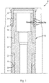
- FIG. 2 the tubing hanger, which is indicated generally by reference number 100, is shown installed in a representative wellhead 10. Similar to the example described above in connection with Figure 1 , the wellhead 10 comprises a central bore 12 within which a number of casing hangers are landed, including an uppermost casing hanger 14 (only the upper portion of which is shown). In this example, the top of the casing hanger 14 is configured as an upward facing seat 16 on which the tubing hanger 100 is landed.
- the tubing hanger 100 includes an axially extending body 102 comprising an annular outer surface.
- a load nut 104 is threadedly connected to the body 102 and includes a downward facing load shoulder 106 which engages the seat 16 when the tubing hanger 100 is landed in the wellhead 10. Due to the threaded connection between the load nut 104 and the body 102, rotation of the load nut relative to the body will result in axial displacement of the load nut relative to the body.
- the tubing hanger 100 is secured to the wellhead 10 by engagement of interacting lockdown features on the tubing hanger and the wellhead.
- the lockdown features may comprise any suitable means for securing the tubing hanger to the wellhead.
- the wellhead may comprise a locking profile in the central bore which is engaged by a lock ring carried on the tubing hanger or on a separate lockdown mandrel or similar device.
- the tubing hanger may comprise a locking profile on the outer surface which is engaged by a number of locking pins or similar devices mounted on the wellhead.
- the tubing hanger lockdown feature comprises a number of expandable locking dogs 108 which are supported on a lockdown ring 110 that is connected to the tubing hanger body 102, and the wellhead lockdown feature comprises a locking profile 32 which is formed in the central bore 12.
- the locking dogs 108 in this example embodiment comprise a number of axially spaced, circumferential locking ridges 108a which are configured to be received in the axially spaced, circumferential locking grooves 32a of the locking profile 32.
- a locking mandrel 112 is actuated to drive the locking ridges 108a into the locking grooves 32a to thereby secure the tubing hanger to the wellhead.
- the vertical distance between the load shoulder 106 and the locking dogs 108 must be the same as the vertical distance between the seat 16 and the locking profile 32.
- the vertical distance between the load shoulder 106 and the locking dogs 108 was adjusted manually.
- the vertical distance between the load shoulder 106 and the locking dogs 108 can be adjusted remotely using a novel coiled piston assembly which will now be described.
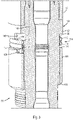
- the coiled piston assembly which is indicated generally by reference number 114, includes an elongated cylinder 116 which is positioned circumferentially around the outer surface of the body 102 axially adjacent the load nut 104, an elongated piston 118 which is slidably received in the cylinder, and a ring-shaped seal 120 which is positioned between the piston and the cylinder.
- the cylinder 116 comprises a first cylinder end 122 which is connected to the body 102 and an open second cylinder end 124.
- the piston 118 comprises a first piston end 126 which is oriented toward the first cylinder end 122 and a second piston end 128 which is configured to extend through the second cylinder end and engage the load nut 104.
- the second piston end 128 may be connected to the load nut 104 by a suitable connector (not shown), or simply configured to bear against the load nut during actuation of the piston assembly 114.
- the seal 120 which may be mounted to either the cylinder 116 or the piston 118, defines a piston chamber 130 between the first cylinder end 122 and the first piston end 126.
- the piston chamber 130 is connectable to a source of fluid pressure (not shown), such as hydraulic fluid, in a manner which will be described below.
- a source of fluid pressure such as hydraulic fluid
- the piston chamber 130 is pressurized to force the piston 118 to extend from the cylinder 116.
- the piston 118 will extend circumferentially relative to the body and generate a torque on the load nut 104 which will cause the load nut to rotate relative to the body. Due to the threaded connection between the load nut 104 and the body 102, this rotation will displace the load nut axially relative to the body and thereby increase the vertical distance between the load shoulder 106 and the locking dogs 108.
- the cylinder 116 and the piston 118 each comprise a helical configuration which is wound around the body 102
- the piston 118 should be made of a material which is capable of maintaining its helical configuration as it extends from the cylinder 116 and winds around the body 102.
- the number of winds the helix of the piston 118 is designed to have will depend on the number of turns the load nut 104 must make to achieve the desired maximum axial displacement of the load nut. In the present embodiment, for example, the piston 118 comprises approximately two full winds.
- the cylinder 116 and the piston 118 are circumferentially aligned with the load nut 104.
- the body 102 includes a first outer surface portion 132 having a first diameter and an axially adjacent second outer surface portion 134 having a second diameter which is less than the first diameter.
- the second outer surface portion 134 defines an annular recessed area between the first outer surface portion 132 and an upper end surface 138 of the load nut 104 within which the piston assembly 114 is positioned.
- the second piston end 128 may be configured to engage a contact surface 138 which extends generally axially from the upper end surface 138 of the load nut 104.
- the second piston end 128 may be connected to or configured to bear against the contact surface 138.
- the piston assembly 114 is operated by communicating fluid pressure to the piston chamber 130 through the first cylinder end 122.
- the first cylinder end 122 is connected to a fluid conduit 140 (shown in phantom) which extends through the body 102 and is connectable to a source of fluid pressure (not shown).
- the first cylinder end 122 may be connected to the fluid conduit 140 by any suitable means, such as a fluid coupling 142.
- the fluid coupling 142 is connected to an end of the fluid conduit 140 which terminates at a radially extending mounting surface 144 that is defined by a recess 146 formed in the first outer surface portion 132 of the body 102.
- the present disclosure is also directed to a method for installing a tubing hanger in a wellhead, such as the wellhead 10 described above.
- the wellhead 10 comprises a first tubing hanger lockdown feature, such as a locking profile 32, and a central bore 10 in which a casing hanger 104 is positioned.
- the tubing hanger which may be similar to the tubing hanger 100 described above, comprises a second tubing hanger lockdown feature, such as a number of locking dogs 108, which is configured to engage the first tubing hanger lockdown feature, an annular body 102, and a load nut 104 which is threadedly connected to the body.
- the load nut 104 comprises a downward facing load shoulder 106 which is configured to land on a seat 16 that is formed on the casing hanger 104.
- the method for installing the tubing hanger 100 in the wellhead 10 comprises the steps of lowering the tubing hanger into the wellhead, and then adjusting the axial position of the load nut 104 until an axial distance between the load shoulder 106 and the second tubing hanger lockdown feature 108 is the same as the axial distance between the seat 16 and the first tubing hanger lockdown feature 32.
- the method also comprises the step of engaging the first and second tubing hanger lockdown features 32, 108 to thereby secure the tubing hanger to the wellhead. This step of engaging the first and second tubing hanger lockdown features 32, 108 may be performed prior to the step of adjusting the axial position of the load nut.
- the method may further comprise the steps of, after the load shoulder 106 is landed on the seat 16 and the first and second lockdown features 32, 108 are engaged, applying a tension to the tubing hanger 100 to obtain a desired preload between the first and second lockdown features, then adjusting the axial position of the load nut 104 until the load shoulder once again engages the seat, and then relieving the tension on the tubing hanger. This action will create a preload between the first and second lockdown features 32, 108 which will tend to rigidize the tubing hanger100 within the wellhead 10.
- the step of adjusting the axial position of the load nut is performed using the piston assembly 114 described above.
- tubing hanger 100 and coiled piston assembly 114 enables the vertical spacing between the load shoulder 106 and the locking dogs 108 to be adjusted in real time as the tubing hanger is landed and locked in the wellhead 10.
- the need to measure the wellhead space-out and adjust the position of the load nut 104 before the tubing hanger is run into the wellhead is eliminated, which greatly reduces the time required to install the tubing hanger.
- the cylinder 116 of the coiled piston assembly 114 is positioned axially adjacent the load nut 104.
- the tubing hanger and coiled piston assembly could be designed such that the cylinder 116 is positioned otherwise relative to the load nut 104.
- the cylinder 116 could be positioned coaxially around the load nut 104.
- an adjustable load nut may comprise outer threads that engage the inner threads of a surrounding member
- the cylinder 116 could be positioned coaxially within the load nut. In each of these examples, the cylinder 116 is considered to be located adjacent the load nut.
- the coiled piston assembly 114 has been described herein in the context of a tubing hanger which is landed on a casing hanger supported in a wellhead, it should be understood that the coiled piston assembly could be used in other applications, either within or outside of the field of subsea hydrocarbon production systems. In the field of subsea hydrocarbon production systems, for example, the coiled piston assembly 114 could be used to obtain proper spacing between any tubular hanger and any component within which the tubular hanger is landed, such as, e.g., a tubing spool or tubing head.
- the present disclosure provides a coiled piston assembly for use in securing an inner member to an outer member that surrounds at least a portion of the inner member.
- the outer member comprises first and second axially spaced outer features and the inner member comprises first and second axially spaced inner features which are configured to engage the outer features to secure the inner member to the outer member.
- the first inner feature is formed on a component which is threadedly connected to the inner member, and the coiled piston assembly is operable to rotate the component to thereby move the first inner feature axially relative to the inner member until the first and second inner features engage the first and second outer features, respectively, to secure the inner member to the outer member.
- the first outer feature may be formed on a component which is threadedly connected to the outer member, and the coiled piston assembly may be operable to rotate the component to thereby move the first outer feature axially relative to the outer member until the first and second inner features engage the first and second outer features, respectively, to secure the inner member to the outer member.
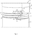
- the coiled piston assembly 114 is shown in conjunction with an inner member 148 which is positioned adjacent an outer member 150.
- the outer member 150 surrounds at least a portion of the inner member 148.
- the inner and outer members 148, 150 may comprise any practical configuration, in Figures 5A and 5B they are each shown to comprise a tubular configuration having a centerline CL.
- the coiled piston assembly 114 is mounted to the inner member 148 adjacent a load nut 152 which is threadedly connected to an outer surface of the inner member such that rotation of the load nut relative to the inner member will result in axial translation of the load nut relative to the inner member.
- the coiled piston assembly 114 includes a cylinder 116 which is connected to the inner member 148, a piston 118 which engages the load nut 152, and a piston chamber 130 which is formed between the first end 122 of the cylinder and the first end 126 of the piston and is connected to a source of pressurized fluid for selective actuation of the piston assembly.
- the outer member 152 comprises first and second axially spaced outer features and the inner member 148 comprises first and second axially spaced inner features which are configured to engage the outer features in order to secure the inner member to the outer member.
- the first outer feature may comprise a seat 154 which is formed on an inner surface of the outer member 150
- the second outer feature may comprise a circumferential groove 156 which is formed on the inner surface of the outer member axially above the seat.
- first inner feature may comprise a shoulder 158 which is formed on an axially lower end of the load nut 152
- second inner feature may comprise a lock ring 160 which is supported on a circular ledge 162 that is formed on an outer surface of the inner member 148 axially above the load nut.
- the inner member is inserted into the outer member until the lock ring 160 is positioned adjacent the groove 156.
- the lock ring 160 is then forced radially outwardly into the groove 156 by means of, e.g., a locking mandrel 164.
- the coiled piston assembly 114 may then be activated to rotate the load nut 152 relative to the inner member 148 to thereby move the load nut axially downward until the shoulder 158 engages the seat 154.
- both the first and second outer features are formed in the outer member 150.
- both the seat on which the tubing hanger is landed and the locking profile for the tubing hanger lockdown mechanism are machined into the axial bore of the tubing head.
- tight tolerances must be maintained in order to ensure that the axial distance between the seat and the locking profile meets the required specifications.
- the manufacturing tolerances can be loosened, because any variation in the axial distance between the seat and the locking profile can be corrected by adjusting the position of the load nut 152 with the coiled piston assembly 114.
- the load nut 152 is threadedly connected to an inner surface of the outer member 150 and the coiled piston assembly 114 is mounted to the outer member adjacent the load nut.
- the first outer feature comprises a seat 168 which is formed on an axially upper end of the load nut 152
- the second outer feature comprises a groove 156 which is formed on the inner surface of the outer member 150 axially above the seat.
- the first inner feature comprises a circumferential shoulder 170 which is formed on the outer surface of the inner member 148
- the second inner feature comprises a lock ring 160 which is supported on the outer surface of the inner member axially above the shoulder.
- the coiled piston assembly 114 includes a cylinder 116 which is connected to the outer member 150, a piston 118 which engages the load nut 152, and a piston chamber 130 which is formed between the first end 122 of the cylinder and the first end 126 of the piston and is connected to a source of pressurized fluid for selective actuation of the piston assembly.
- the inner member is inserted into the outer member until the lock ring 160 is positioned adjacent the groove 156.
- the lock ring 160 is then forced radially outwardly into the groove 156 by, e.g., a locking mandrel 164.
- the coiled piston assembly 114 may then be activated to rotate the load nut 152 relative to the outer member 150 to thereby move the load nut axially upward until the seat 168 engages the shoulder 170.
- a force may be applied to the inner member in a direction opposite to the direction of insertion in order to preload the lock ring against the groove.
- the coiled piston assembly 114 may then be activated to move the load nut 152 axially upward until the seat 168 engages the shoulder 170.
- a tubing hanger assembly which includes:
- Clause 4 The tubing hanger assembly of clause 2, wherein the body includes a first outer surface portion comprising a first diameter and an axially adjacent second outer surface portion comprising a second diameter which is less than the first diameter, and wherein the piston assembly is positioned around the second outer surface portion.
- Clause 7 The tubing hanger assembly of clause 5, wherein the first outer surface portion comprises a recess which defines a radially extending mounting surface to which the first cylinder end is connected.
- Clause 8 The tubing hanger assembly of clause 7, wherein the body includes a fluid conduit which is connectable to the source of fluid pressure and comprises a first conduit end that terminates at the mounting surface, and wherein the first cylinder end is connected to the first conduit end via a fluid coupling.
- tubing hanger assembly of clause 1 wherein the tubing hanger assembly is configured to be installed in a wellhead which comprises a central bore in which a casing hanger is positioned, the load shoulder being configured to land on a seat which is formed on the casing hanger to thereby support the tubing hanger in the wellhead.
- a method for installing a tubing hanger in a wellhead comprising a first tubing hanger lockdown feature and a central bore in which a casing hanger is positioned, and the tubing hanger comprising a second tubing hanger lockdown feature which is configured to engage the first tubing hanger lockdown feature, an annular body, and a load nut which is threadedly connected to the body, the load nut comprising a downward facing load shoulder which is configured to land on a seat that is formed on the casing hanger, the method comprising:
- Clause 13 The method of clause 12, further comprising engaging the first and second tubing hanger lockdown features to thereby secure the tubing hanger to the wellhead.
- Clause 14 The method of clause 13, wherein the step of engaging the first tubing hanger lockdown feature with the second tubing hanger lockdown feature is performed prior to the step of adjusting the axial position of the load nut.
- the tubing hanger further comprises a piston assembly which is positioned circumferentially around the body, the piston assembly comprising an elongated cylinder which is connected to the body and an elongated piston which is slidably received in the cylinder and is configured to extend from the cylinder and engage the load nut such that extension of the piston causes the load nut to rotate relative to the body, and wherein the step of adjusting the axial position of the load nut is performed by operating the piston assembly.
- a piston assembly which includes:
- a piston assembly for use in securing an inner member to an outer member which surrounds at least a portion of the inner member, the inner member comprising first and second axially spaced inner features and the outer member comprising first and second axially spaced outer features which are configured to engage the first and second inner features, respectively, to secure the inner member to the outer member, one of the first inner feature and the first outer feature being formed on a load nut which is threadedly connected to one of the inner member and the outer member such that rotation of the load nut relative to said one of the inner member and the outer member moves the load nut axially relative to said one of the inner member and the outer member, the piston assembly comprising:
- Clause 20 The method of clause 19, further comprising: prior to the step of operating the piston assembly to rotate the load nut to thereby move the first inner feature into engagement with the first outer feature, applying a preload force on the inner member in a direction opposite to a direction in which the inner member is inserted into the outer member.
Landscapes
- Geology (AREA)
- Life Sciences & Earth Sciences (AREA)
- Engineering & Computer Science (AREA)
- Mining & Mineral Resources (AREA)
- Environmental & Geological Engineering (AREA)
- Fluid Mechanics (AREA)
- Physics & Mathematics (AREA)
- General Life Sciences & Earth Sciences (AREA)
- Geochemistry & Mineralogy (AREA)
- Mechanical Engineering (AREA)
- Structural Engineering (AREA)
- Earth Drilling (AREA)
- Actuator (AREA)
- Pivots And Pivotal Connections (AREA)
- Pistons, Piston Rings, And Cylinders (AREA)
Priority Applications (2)
| Application Number | Priority Date | Filing Date | Title |
|---|---|---|---|
| EP24170437.8A EP4375477A3 (de) | 2017-06-09 | 2017-06-09 | Gewickelte kolbenanordnung |
| EP22184965.6A EP4092245B1 (de) | 2017-06-09 | 2017-06-09 | Spiralkolbenanordnung |
Applications Claiming Priority (3)
| Application Number | Priority Date | Filing Date | Title |
|---|---|---|---|
| EP17912601.6A EP3635213B1 (de) | 2017-06-09 | 2017-06-09 | Spiralkolbenanordnung |
| PCT/US2017/036722 WO2018226239A1 (en) | 2017-06-09 | 2017-06-09 | Coiled piston assembly |
| EP22184965.6A EP4092245B1 (de) | 2017-06-09 | 2017-06-09 | Spiralkolbenanordnung |
Related Parent Applications (2)
| Application Number | Title | Priority Date | Filing Date |
|---|---|---|---|
| EP17912601.6A Division EP3635213B1 (de) | 2017-06-09 | 2017-06-09 | Spiralkolbenanordnung |
| EP17912601.6A Division-Into EP3635213B1 (de) | 2017-06-09 | 2017-06-09 | Spiralkolbenanordnung |
Related Child Applications (2)
| Application Number | Title | Priority Date | Filing Date |
|---|---|---|---|
| EP24170437.8A Division EP4375477A3 (de) | 2017-06-09 | 2017-06-09 | Gewickelte kolbenanordnung |
| EP24170437.8A Division-Into EP4375477A3 (de) | 2017-06-09 | 2017-06-09 | Gewickelte kolbenanordnung |
Publications (3)
| Publication Number | Publication Date |
|---|---|
| EP4092245A2 true EP4092245A2 (de) | 2022-11-23 |
| EP4092245A3 EP4092245A3 (de) | 2022-12-21 |
| EP4092245B1 EP4092245B1 (de) | 2024-05-22 |
Family
ID=64567228
Family Applications (3)
| Application Number | Title | Priority Date | Filing Date |
|---|---|---|---|
| EP24170437.8A Pending EP4375477A3 (de) | 2017-06-09 | 2017-06-09 | Gewickelte kolbenanordnung |
| EP22184965.6A Active EP4092245B1 (de) | 2017-06-09 | 2017-06-09 | Spiralkolbenanordnung |
| EP17912601.6A Active EP3635213B1 (de) | 2017-06-09 | 2017-06-09 | Spiralkolbenanordnung |
Family Applications Before (1)
| Application Number | Title | Priority Date | Filing Date |
|---|---|---|---|
| EP24170437.8A Pending EP4375477A3 (de) | 2017-06-09 | 2017-06-09 | Gewickelte kolbenanordnung |
Family Applications After (1)
| Application Number | Title | Priority Date | Filing Date |
|---|---|---|---|
| EP17912601.6A Active EP3635213B1 (de) | 2017-06-09 | 2017-06-09 | Spiralkolbenanordnung |
Country Status (5)
| Country | Link |
|---|---|
| US (2) | US11332995B2 (de) |
| EP (3) | EP4375477A3 (de) |
| AU (1) | AU2017417925B2 (de) |
| BR (1) | BR112019024110B1 (de) |
| WO (1) | WO2018226239A1 (de) |
Families Citing this family (9)
| Publication number | Priority date | Publication date | Assignee | Title |
|---|---|---|---|---|
| US12577846B2 (en) | 2017-10-19 | 2026-03-17 | Innovex International, Inc. | Tubing hanger alignment device and space-out mechanism |
| US12152456B2 (en) | 2019-12-12 | 2024-11-26 | Innovex International, Inc. | Rigidized seal assembly using automated space-out mechanism |
| US10830015B2 (en) | 2017-10-19 | 2020-11-10 | Dril-Quip, Inc. | Tubing hanger alignment device |
| US11180968B2 (en) | 2017-10-19 | 2021-11-23 | Dril-Quip, Inc. | Tubing hanger alignment device |
| US11180969B2 (en) * | 2017-11-07 | 2021-11-23 | Fmc Technologies, Inc. | Spring actuated adjustable load nut |
| GB2611660B (en) * | 2019-01-07 | 2023-10-04 | Dril Quip Inc | One trip lockdown sleeve and running tool |
| GB2591600B (en) | 2019-12-12 | 2023-11-15 | Dril Quip Inc | A system comprising a tubing hanger body and a space-out mechanism and method |
| US12404734B2 (en) | 2019-12-12 | 2025-09-02 | Innovex International, Inc. | Lock ring actuator for tubing hanger installation |
| US12404764B2 (en) | 2023-07-12 | 2025-09-02 | Saudi Arabian Oil Company | Completion nipple identifier tool |
Family Cites Families (14)
| Publication number | Priority date | Publication date | Assignee | Title |
|---|---|---|---|---|
| US1823132A (en) * | 1927-06-08 | 1931-09-15 | Michael J Cunningham | Rotary internal combustion engine |
| US2824757A (en) * | 1955-04-04 | 1958-02-25 | George A Butler | Pipe suspension and sealing means with means to limit compression of the seal |
| US3338137A (en) * | 1965-07-26 | 1967-08-29 | Richard James Cylindrical Moto | Piston power units |
| GB8615200D0 (en) * | 1986-06-21 | 1986-07-23 | Plexus Ocean Syst Ltd | Tie-back hanger |
| CA2141510C (en) | 1995-01-31 | 1997-01-21 | Andrew Wright | Tubing string hanging apparatus |
| GB2347161B (en) | 1999-02-11 | 2000-11-08 | Fmc Corp | Large bore subsea christmas tree and tubing hanger system |
| US6179053B1 (en) | 1999-08-12 | 2001-01-30 | L. Murray Dallas | Lockdown mechanism for well tools requiring fixed-point packoff |
| US7431351B2 (en) * | 2002-04-26 | 2008-10-07 | Russell Larry R | Pressure-containing tubular connections for remote operation |
| US7104345B2 (en) | 2004-06-22 | 2006-09-12 | Pathfinder Energy Services, Inc. | Downhole rotatable-shaft connector assembly and method |
| CN102099542B (zh) * | 2008-07-18 | 2014-03-12 | 诺埃提克技术公司 | 为夹持工具提供改进操作范围和能力的三凸轮轴向扩展 |
| WO2011115601A1 (en) * | 2010-03-15 | 2011-09-22 | Fmc Technologies, Inc. | Optical scanning tool for wellheads |
| GB2516272A (en) * | 2013-07-17 | 2015-01-21 | Ronen Perlin | Piston |
| US10113384B2 (en) * | 2015-03-11 | 2018-10-30 | Cameron International Corporation | Multi-metal seal system |
| EP3563027B1 (de) * | 2016-12-30 | 2023-07-19 | Cameron Technologies Limited | Laufwerkzeuganordnungen und verfahren |
-
2017
- 2017-06-09 EP EP24170437.8A patent/EP4375477A3/de active Pending
- 2017-06-09 BR BR112019024110-8A patent/BR112019024110B1/pt active IP Right Grant
- 2017-06-09 EP EP22184965.6A patent/EP4092245B1/de active Active
- 2017-06-09 WO PCT/US2017/036722 patent/WO2018226239A1/en not_active Ceased
- 2017-06-09 AU AU2017417925A patent/AU2017417925B2/en active Active
- 2017-06-09 US US16/606,679 patent/US11332995B2/en active Active
- 2017-06-09 EP EP17912601.6A patent/EP3635213B1/de active Active
-
2022
- 2022-04-22 US US17/727,467 patent/US11988062B2/en active Active
Also Published As
| Publication number | Publication date |
|---|---|
| BR112019024110A2 (pt) | 2020-06-02 |
| BR112019024110B1 (pt) | 2023-05-09 |
| US11988062B2 (en) | 2024-05-21 |
| EP3635213A1 (de) | 2020-04-15 |
| EP4375477A3 (de) | 2024-08-14 |
| AU2017417925A1 (en) | 2019-11-07 |
| US11332995B2 (en) | 2022-05-17 |
| AU2017417925B2 (en) | 2023-02-16 |
| EP4092245B1 (de) | 2024-05-22 |
| US20220243550A1 (en) | 2022-08-04 |
| EP3635213A4 (de) | 2021-01-27 |
| EP4375477A2 (de) | 2024-05-29 |
| US20210396090A1 (en) | 2021-12-23 |
| EP3635213B1 (de) | 2022-09-07 |
| EP4092245A3 (de) | 2022-12-21 |
| WO2018226239A1 (en) | 2018-12-13 |
Similar Documents
| Publication | Publication Date | Title |
|---|---|---|
| US11988062B2 (en) | Coiled piston assembly | |
| US11920423B2 (en) | Tubing hanger assembly with adjustable load nut | |
| CN108386146B (zh) | 深水钻井用套管头与环空密封装置下入工具及其使用方法 | |
| US6349770B1 (en) | Telescoping tool | |
| EP2374990B1 (de) | Brückenhängervorrichtung und Dichtungseinbauwerkzeug | |
| US7647973B2 (en) | Collapse arrestor tool | |
| US4634152A (en) | Casing hanger running tool | |
| US7231970B2 (en) | Non-rotational casing hanger and seal assembly running tool | |
| US10066456B2 (en) | Well assembly with self-adjusting lockdown assembly | |
| US8261818B2 (en) | Self-inserting seal assembly | |
| US6401827B1 (en) | Tubing hanger running tool | |
| US20140158376A1 (en) | Adjustable hanger system and method | |
| US20020074116A1 (en) | Downhole packer | |
| US20020157824A1 (en) | Downhole tool | |
| WO2026011042A1 (en) | Sting, punch tool, and method for perforating and plugging a downhole tubular | |
| NO20250467A1 (en) | Improved downhole high expansion anchor system | |
| WO2024081100A1 (en) | Drill-through tubing head assembly |
Legal Events
| Date | Code | Title | Description |
|---|---|---|---|
| PUAI | Public reference made under article 153(3) epc to a published international application that has entered the european phase |
Free format text: ORIGINAL CODE: 0009012 |
|
| STAA | Information on the status of an ep patent application or granted ep patent |
Free format text: STATUS: THE APPLICATION HAS BEEN PUBLISHED |
|
| PUAL | Search report despatched |
Free format text: ORIGINAL CODE: 0009013 |
|
| AC | Divisional application: reference to earlier application |
Ref document number: 3635213 Country of ref document: EP Kind code of ref document: P |
|
| AK | Designated contracting states |
Kind code of ref document: A2 Designated state(s): AL AT BE BG CH CY CZ DE DK EE ES FI FR GB GR HR HU IE IS IT LI LT LU LV MC MK MT NL NO PL PT RO RS SE SI SK SM TR |
|
| AK | Designated contracting states |
Kind code of ref document: A3 Designated state(s): AL AT BE BG CH CY CZ DE DK EE ES FI FR GB GR HR HU IE IS IT LI LT LU LV MC MK MT NL NO PL PT RO RS SE SI SK SM TR |
|
| RIC1 | Information provided on ipc code assigned before grant |
Ipc: E21B 33/04 20060101ALI20221114BHEP Ipc: E21B 33/043 20060101AFI20221114BHEP |
|
| STAA | Information on the status of an ep patent application or granted ep patent |
Free format text: STATUS: REQUEST FOR EXAMINATION WAS MADE |
|
| 17P | Request for examination filed |
Effective date: 20230424 |
|
| RBV | Designated contracting states (corrected) |
Designated state(s): AL AT BE BG CH CY CZ DE DK EE ES FI FR GB GR HR HU IE IS IT LI LT LU LV MC MK MT NL NO PL PT RO RS SE SI SK SM TR |
|
| GRAP | Despatch of communication of intention to grant a patent |
Free format text: ORIGINAL CODE: EPIDOSNIGR1 |
|
| STAA | Information on the status of an ep patent application or granted ep patent |
Free format text: STATUS: GRANT OF PATENT IS INTENDED |
|
| INTG | Intention to grant announced |
Effective date: 20240129 |
|
| GRAS | Grant fee paid |
Free format text: ORIGINAL CODE: EPIDOSNIGR3 |
|
| GRAA | (expected) grant |
Free format text: ORIGINAL CODE: 0009210 |
|
| STAA | Information on the status of an ep patent application or granted ep patent |
Free format text: STATUS: THE PATENT HAS BEEN GRANTED |
|
| AC | Divisional application: reference to earlier application |
Ref document number: 3635213 Country of ref document: EP Kind code of ref document: P |
|
| AK | Designated contracting states |
Kind code of ref document: B1 Designated state(s): AL AT BE BG CH CY CZ DE DK EE ES FI FR GB GR HR HU IE IS IT LI LT LU LV MC MK MT NL NO PL PT RO RS SE SI SK SM TR |
|
| REG | Reference to a national code |
Ref country code: GB Ref legal event code: FG4D |
|
| REG | Reference to a national code |
Ref country code: CH Ref legal event code: EP |
|
| REG | Reference to a national code |
Ref country code: DE Ref legal event code: R096 Ref document number: 602017082227 Country of ref document: DE |
|
| REG | Reference to a national code |
Ref country code: IE Ref legal event code: FG4D |
|
| P01 | Opt-out of the competence of the unified patent court (upc) registered |
Effective date: 20240522 |
|
| REG | Reference to a national code |
Ref country code: LT Ref legal event code: MG9D |
|
| REG | Reference to a national code |
Ref country code: NL Ref legal event code: MP Effective date: 20240522 |
|
| PG25 | Lapsed in a contracting state [announced via postgrant information from national office to epo] |
Ref country code: IS Free format text: LAPSE BECAUSE OF FAILURE TO SUBMIT A TRANSLATION OF THE DESCRIPTION OR TO PAY THE FEE WITHIN THE PRESCRIBED TIME-LIMIT Effective date: 20240922 |
|
| PG25 | Lapsed in a contracting state [announced via postgrant information from national office to epo] |
Ref country code: BG Free format text: LAPSE BECAUSE OF FAILURE TO SUBMIT A TRANSLATION OF THE DESCRIPTION OR TO PAY THE FEE WITHIN THE PRESCRIBED TIME-LIMIT Effective date: 20240522 |
|
| PG25 | Lapsed in a contracting state [announced via postgrant information from national office to epo] |
Ref country code: HR Free format text: LAPSE BECAUSE OF FAILURE TO SUBMIT A TRANSLATION OF THE DESCRIPTION OR TO PAY THE FEE WITHIN THE PRESCRIBED TIME-LIMIT Effective date: 20240522 Ref country code: FI Free format text: LAPSE BECAUSE OF FAILURE TO SUBMIT A TRANSLATION OF THE DESCRIPTION OR TO PAY THE FEE WITHIN THE PRESCRIBED TIME-LIMIT Effective date: 20240522 |
|
| PG25 | Lapsed in a contracting state [announced via postgrant information from national office to epo] |
Ref country code: GR Free format text: LAPSE BECAUSE OF FAILURE TO SUBMIT A TRANSLATION OF THE DESCRIPTION OR TO PAY THE FEE WITHIN THE PRESCRIBED TIME-LIMIT Effective date: 20240823 |
|
| PG25 | Lapsed in a contracting state [announced via postgrant information from national office to epo] |
Ref country code: PT Free format text: LAPSE BECAUSE OF FAILURE TO SUBMIT A TRANSLATION OF THE DESCRIPTION OR TO PAY THE FEE WITHIN THE PRESCRIBED TIME-LIMIT Effective date: 20240923 |
|
| REG | Reference to a national code |
Ref country code: AT Ref legal event code: MK05 Ref document number: 1688915 Country of ref document: AT Kind code of ref document: T Effective date: 20240522 |
|
| PG25 | Lapsed in a contracting state [announced via postgrant information from national office to epo] |
Ref country code: NL Free format text: LAPSE BECAUSE OF FAILURE TO SUBMIT A TRANSLATION OF THE DESCRIPTION OR TO PAY THE FEE WITHIN THE PRESCRIBED TIME-LIMIT Effective date: 20240522 |
|
| PG25 | Lapsed in a contracting state [announced via postgrant information from national office to epo] |
Ref country code: ES Free format text: LAPSE BECAUSE OF FAILURE TO SUBMIT A TRANSLATION OF THE DESCRIPTION OR TO PAY THE FEE WITHIN THE PRESCRIBED TIME-LIMIT Effective date: 20240522 |
|
| PG25 | Lapsed in a contracting state [announced via postgrant information from national office to epo] |
Ref country code: AT Free format text: LAPSE BECAUSE OF FAILURE TO SUBMIT A TRANSLATION OF THE DESCRIPTION OR TO PAY THE FEE WITHIN THE PRESCRIBED TIME-LIMIT Effective date: 20240522 |
|
| PG25 | Lapsed in a contracting state [announced via postgrant information from national office to epo] |
Ref country code: PL Free format text: LAPSE BECAUSE OF FAILURE TO SUBMIT A TRANSLATION OF THE DESCRIPTION OR TO PAY THE FEE WITHIN THE PRESCRIBED TIME-LIMIT Effective date: 20240522 |
|
| PG25 | Lapsed in a contracting state [announced via postgrant information from national office to epo] |
Ref country code: LV Free format text: LAPSE BECAUSE OF FAILURE TO SUBMIT A TRANSLATION OF THE DESCRIPTION OR TO PAY THE FEE WITHIN THE PRESCRIBED TIME-LIMIT Effective date: 20240522 |
|
| PG25 | Lapsed in a contracting state [announced via postgrant information from national office to epo] |
Ref country code: PT Free format text: LAPSE BECAUSE OF FAILURE TO SUBMIT A TRANSLATION OF THE DESCRIPTION OR TO PAY THE FEE WITHIN THE PRESCRIBED TIME-LIMIT Effective date: 20240923 Ref country code: PL Free format text: LAPSE BECAUSE OF FAILURE TO SUBMIT A TRANSLATION OF THE DESCRIPTION OR TO PAY THE FEE WITHIN THE PRESCRIBED TIME-LIMIT Effective date: 20240522 Ref country code: NL Free format text: LAPSE BECAUSE OF FAILURE TO SUBMIT A TRANSLATION OF THE DESCRIPTION OR TO PAY THE FEE WITHIN THE PRESCRIBED TIME-LIMIT Effective date: 20240522 Ref country code: LV Free format text: LAPSE BECAUSE OF FAILURE TO SUBMIT A TRANSLATION OF THE DESCRIPTION OR TO PAY THE FEE WITHIN THE PRESCRIBED TIME-LIMIT Effective date: 20240522 Ref country code: IS Free format text: LAPSE BECAUSE OF FAILURE TO SUBMIT A TRANSLATION OF THE DESCRIPTION OR TO PAY THE FEE WITHIN THE PRESCRIBED TIME-LIMIT Effective date: 20240922 Ref country code: HR Free format text: LAPSE BECAUSE OF FAILURE TO SUBMIT A TRANSLATION OF THE DESCRIPTION OR TO PAY THE FEE WITHIN THE PRESCRIBED TIME-LIMIT Effective date: 20240522 Ref country code: GR Free format text: LAPSE BECAUSE OF FAILURE TO SUBMIT A TRANSLATION OF THE DESCRIPTION OR TO PAY THE FEE WITHIN THE PRESCRIBED TIME-LIMIT Effective date: 20240823 Ref country code: FI Free format text: LAPSE BECAUSE OF FAILURE TO SUBMIT A TRANSLATION OF THE DESCRIPTION OR TO PAY THE FEE WITHIN THE PRESCRIBED TIME-LIMIT Effective date: 20240522 Ref country code: ES Free format text: LAPSE BECAUSE OF FAILURE TO SUBMIT A TRANSLATION OF THE DESCRIPTION OR TO PAY THE FEE WITHIN THE PRESCRIBED TIME-LIMIT Effective date: 20240522 Ref country code: BG Free format text: LAPSE BECAUSE OF FAILURE TO SUBMIT A TRANSLATION OF THE DESCRIPTION OR TO PAY THE FEE WITHIN THE PRESCRIBED TIME-LIMIT Effective date: 20240522 Ref country code: AT Free format text: LAPSE BECAUSE OF FAILURE TO SUBMIT A TRANSLATION OF THE DESCRIPTION OR TO PAY THE FEE WITHIN THE PRESCRIBED TIME-LIMIT Effective date: 20240522 Ref country code: RS Free format text: LAPSE BECAUSE OF FAILURE TO SUBMIT A TRANSLATION OF THE DESCRIPTION OR TO PAY THE FEE WITHIN THE PRESCRIBED TIME-LIMIT Effective date: 20240822 |
|
| REG | Reference to a national code |
Ref country code: DE Ref legal event code: R119 Ref document number: 602017082227 Country of ref document: DE |
|
| PG25 | Lapsed in a contracting state [announced via postgrant information from national office to epo] |
Ref country code: DK Free format text: LAPSE BECAUSE OF FAILURE TO SUBMIT A TRANSLATION OF THE DESCRIPTION OR TO PAY THE FEE WITHIN THE PRESCRIBED TIME-LIMIT Effective date: 20240522 |
|
| PG25 | Lapsed in a contracting state [announced via postgrant information from national office to epo] |
Ref country code: EE Free format text: LAPSE BECAUSE OF FAILURE TO SUBMIT A TRANSLATION OF THE DESCRIPTION OR TO PAY THE FEE WITHIN THE PRESCRIBED TIME-LIMIT Effective date: 20240522 |
|
| PG25 | Lapsed in a contracting state [announced via postgrant information from national office to epo] |
Ref country code: CZ Free format text: LAPSE BECAUSE OF FAILURE TO SUBMIT A TRANSLATION OF THE DESCRIPTION OR TO PAY THE FEE WITHIN THE PRESCRIBED TIME-LIMIT Effective date: 20240522 |
|
| PG25 | Lapsed in a contracting state [announced via postgrant information from national office to epo] |
Ref country code: RO Free format text: LAPSE BECAUSE OF FAILURE TO SUBMIT A TRANSLATION OF THE DESCRIPTION OR TO PAY THE FEE WITHIN THE PRESCRIBED TIME-LIMIT Effective date: 20240522 Ref country code: SK Free format text: LAPSE BECAUSE OF FAILURE TO SUBMIT A TRANSLATION OF THE DESCRIPTION OR TO PAY THE FEE WITHIN THE PRESCRIBED TIME-LIMIT Effective date: 20240522 |
|
| PG25 | Lapsed in a contracting state [announced via postgrant information from national office to epo] |
Ref country code: SK Free format text: LAPSE BECAUSE OF FAILURE TO SUBMIT A TRANSLATION OF THE DESCRIPTION OR TO PAY THE FEE WITHIN THE PRESCRIBED TIME-LIMIT Effective date: 20240522 Ref country code: RO Free format text: LAPSE BECAUSE OF FAILURE TO SUBMIT A TRANSLATION OF THE DESCRIPTION OR TO PAY THE FEE WITHIN THE PRESCRIBED TIME-LIMIT Effective date: 20240522 Ref country code: EE Free format text: LAPSE BECAUSE OF FAILURE TO SUBMIT A TRANSLATION OF THE DESCRIPTION OR TO PAY THE FEE WITHIN THE PRESCRIBED TIME-LIMIT Effective date: 20240522 Ref country code: DK Free format text: LAPSE BECAUSE OF FAILURE TO SUBMIT A TRANSLATION OF THE DESCRIPTION OR TO PAY THE FEE WITHIN THE PRESCRIBED TIME-LIMIT Effective date: 20240522 Ref country code: CZ Free format text: LAPSE BECAUSE OF FAILURE TO SUBMIT A TRANSLATION OF THE DESCRIPTION OR TO PAY THE FEE WITHIN THE PRESCRIBED TIME-LIMIT Effective date: 20240522 |
|
| REG | Reference to a national code |
Ref country code: CH Ref legal event code: PL |
|
| PG25 | Lapsed in a contracting state [announced via postgrant information from national office to epo] |
Ref country code: MC Free format text: LAPSE BECAUSE OF FAILURE TO SUBMIT A TRANSLATION OF THE DESCRIPTION OR TO PAY THE FEE WITHIN THE PRESCRIBED TIME-LIMIT Effective date: 20240522 |
|
| PG25 | Lapsed in a contracting state [announced via postgrant information from national office to epo] |
Ref country code: LU Free format text: LAPSE BECAUSE OF NON-PAYMENT OF DUE FEES Effective date: 20240609 |
|
| PLBE | No opposition filed within time limit |
Free format text: ORIGINAL CODE: 0009261 |
|
| STAA | Information on the status of an ep patent application or granted ep patent |
Free format text: STATUS: NO OPPOSITION FILED WITHIN TIME LIMIT |
|
| PG25 | Lapsed in a contracting state [announced via postgrant information from national office to epo] |
Ref country code: DE Free format text: LAPSE BECAUSE OF NON-PAYMENT OF DUE FEES Effective date: 20250101 |
|
| PG25 | Lapsed in a contracting state [announced via postgrant information from national office to epo] |
Ref country code: IE Free format text: LAPSE BECAUSE OF NON-PAYMENT OF DUE FEES Effective date: 20240609 |
|
| PG25 | Lapsed in a contracting state [announced via postgrant information from national office to epo] |
Ref country code: BE Free format text: LAPSE BECAUSE OF NON-PAYMENT OF DUE FEES Effective date: 20240630 Ref country code: SI Free format text: LAPSE BECAUSE OF FAILURE TO SUBMIT A TRANSLATION OF THE DESCRIPTION OR TO PAY THE FEE WITHIN THE PRESCRIBED TIME-LIMIT Effective date: 20240522 Ref country code: CH Free format text: LAPSE BECAUSE OF NON-PAYMENT OF DUE FEES Effective date: 20240630 |
|
| 26N | No opposition filed |
Effective date: 20250225 |
|
| REG | Reference to a national code |
Ref country code: BE Ref legal event code: MM Effective date: 20240630 |
|
| PGFP | Annual fee paid to national office [announced via postgrant information from national office to epo] |
Ref country code: GB Payment date: 20250401 Year of fee payment: 9 |
|
| PGFP | Annual fee paid to national office [announced via postgrant information from national office to epo] |
Ref country code: NO Payment date: 20250610 Year of fee payment: 9 |
|
| PGFP | Annual fee paid to national office [announced via postgrant information from national office to epo] |
Ref country code: IT Payment date: 20250522 Year of fee payment: 9 |
|
| PGFP | Annual fee paid to national office [announced via postgrant information from national office to epo] |
Ref country code: FR Payment date: 20250401 Year of fee payment: 9 |
|
| PG25 | Lapsed in a contracting state [announced via postgrant information from national office to epo] |
Ref country code: SE Free format text: LAPSE BECAUSE OF FAILURE TO SUBMIT A TRANSLATION OF THE DESCRIPTION OR TO PAY THE FEE WITHIN THE PRESCRIBED TIME-LIMIT Effective date: 20240522 |
|
| PG25 | Lapsed in a contracting state [announced via postgrant information from national office to epo] |
Ref country code: SM Free format text: LAPSE BECAUSE OF FAILURE TO SUBMIT A TRANSLATION OF THE DESCRIPTION OR TO PAY THE FEE WITHIN THE PRESCRIBED TIME-LIMIT; INVALID AB INITIO Effective date: 20170609 |
|
| PG25 | Lapsed in a contracting state [announced via postgrant information from national office to epo] |
Ref country code: CY Free format text: LAPSE BECAUSE OF FAILURE TO SUBMIT A TRANSLATION OF THE DESCRIPTION OR TO PAY THE FEE WITHIN THE PRESCRIBED TIME-LIMIT; INVALID AB INITIO Effective date: 20170609 |
|
| PG25 | Lapsed in a contracting state [announced via postgrant information from national office to epo] |
Ref country code: HU Free format text: LAPSE BECAUSE OF FAILURE TO SUBMIT A TRANSLATION OF THE DESCRIPTION OR TO PAY THE FEE WITHIN THE PRESCRIBED TIME-LIMIT; INVALID AB INITIO Effective date: 20170609 |