EP4092175A1 - Window seal for laundry treatment device, and laundry treatment device - Google Patents
Window seal for laundry treatment device, and laundry treatment device Download PDFInfo
- Publication number
- EP4092175A1 EP4092175A1 EP20913996.3A EP20913996A EP4092175A1 EP 4092175 A1 EP4092175 A1 EP 4092175A1 EP 20913996 A EP20913996 A EP 20913996A EP 4092175 A1 EP4092175 A1 EP 4092175A1
- Authority
- EP
- European Patent Office
- Prior art keywords
- groove
- window pad
- drying air
- guide part
- air
- Prior art date
- Legal status (The legal status is an assumption and is not a legal conclusion. Google has not performed a legal analysis and makes no representation as to the accuracy of the status listed.)
- Pending
Links
- 238000001035 drying Methods 0.000 claims abstract description 149
- 230000037303 wrinkles Effects 0.000 claims abstract description 6
- 230000004888 barrier function Effects 0.000 claims description 29
- 238000007789 sealing Methods 0.000 claims description 28
- 238000005406 washing Methods 0.000 abstract description 36
- 239000006260 foam Substances 0.000 abstract description 24
- XLYOFNOQVPJJNP-UHFFFAOYSA-N water Substances O XLYOFNOQVPJJNP-UHFFFAOYSA-N 0.000 abstract description 23
- 238000007605 air drying Methods 0.000 abstract description 4
- 238000009423 ventilation Methods 0.000 abstract description 3
- 238000010586 diagram Methods 0.000 description 5
- 230000009286 beneficial effect Effects 0.000 description 3
- 238000000861 blow drying Methods 0.000 description 3
- 238000007664 blowing Methods 0.000 description 3
- 230000000694 effects Effects 0.000 description 3
- 238000000605 extraction Methods 0.000 description 2
- 238000003780 insertion Methods 0.000 description 2
- 230000037431 insertion Effects 0.000 description 2
- 238000004519 manufacturing process Methods 0.000 description 2
- 239000000463 material Substances 0.000 description 2
- 238000012986 modification Methods 0.000 description 2
- 230000004048 modification Effects 0.000 description 2
- 238000004140 cleaning Methods 0.000 description 1
- 230000007547 defect Effects 0.000 description 1
Images

Classifications
-
- D—TEXTILES; PAPER
- D06—TREATMENT OF TEXTILES OR THE LIKE; LAUNDERING; FLEXIBLE MATERIALS NOT OTHERWISE PROVIDED FOR
- D06F—LAUNDERING, DRYING, IRONING, PRESSING OR FOLDING TEXTILE ARTICLES
- D06F39/00—Details of washing machines not specific to a single type of machines covered by groups D06F9/00 - D06F27/00
-
- D—TEXTILES; PAPER
- D06—TREATMENT OF TEXTILES OR THE LIKE; LAUNDERING; FLEXIBLE MATERIALS NOT OTHERWISE PROVIDED FOR
- D06F—LAUNDERING, DRYING, IRONING, PRESSING OR FOLDING TEXTILE ARTICLES
- D06F37/00—Details specific to washing machines covered by groups D06F21/00 - D06F25/00
- D06F37/26—Casings; Tubs
- D06F37/267—Tubs specially adapted for mounting thereto components or devices not provided for in preceding subgroups
-
- D—TEXTILES; PAPER
- D06—TREATMENT OF TEXTILES OR THE LIKE; LAUNDERING; FLEXIBLE MATERIALS NOT OTHERWISE PROVIDED FOR
- D06F—LAUNDERING, DRYING, IRONING, PRESSING OR FOLDING TEXTILE ARTICLES
- D06F25/00—Washing machines with receptacles, e.g. perforated, having a rotary movement, e.g. oscillatory movement, the receptacle serving both for washing and for centrifugally separating water from the laundry and having further drying means, e.g. using hot air
-
- D—TEXTILES; PAPER
- D06—TREATMENT OF TEXTILES OR THE LIKE; LAUNDERING; FLEXIBLE MATERIALS NOT OTHERWISE PROVIDED FOR
- D06F—LAUNDERING, DRYING, IRONING, PRESSING OR FOLDING TEXTILE ARTICLES
- D06F58/00—Domestic laundry dryers
- D06F58/20—General details of domestic laundry dryers
-
- D—TEXTILES; PAPER
- D06—TREATMENT OF TEXTILES OR THE LIKE; LAUNDERING; FLEXIBLE MATERIALS NOT OTHERWISE PROVIDED FOR
- D06F—LAUNDERING, DRYING, IRONING, PRESSING OR FOLDING TEXTILE ARTICLES
- D06F37/00—Details specific to washing machines covered by groups D06F21/00 - D06F25/00
- D06F37/26—Casings; Tubs
- D06F37/266—Gaskets mounted between tub and casing around the loading opening
-
- D—TEXTILES; PAPER
- D06—TREATMENT OF TEXTILES OR THE LIKE; LAUNDERING; FLEXIBLE MATERIALS NOT OTHERWISE PROVIDED FOR
- D06F—LAUNDERING, DRYING, IRONING, PRESSING OR FOLDING TEXTILE ARTICLES
- D06F58/00—Domestic laundry dryers
- D06F58/02—Domestic laundry dryers having dryer drums rotating about a horizontal axis
Definitions
- the invention belongs to the technical field of laundry treatment devices, and particularly relates to a window pad of a laundry treatment device, and a laundry treatment device.
- the groove structure of the window pad is improved, a water discharge port is formed in the bottom of the groove. But residual water can be partially discharged, and foam existing in the groove cannot be easily removed through the water discharge port.
- the technical problem to be solved by the invention is to overcome the defects in the prior art, and a window pad of a laundry treatment device is provided.
- a part of a groove in the circumferential direction of the window pad is covered with an air guide part to form an air channel for guiding drying air to residual water and foam.
- the ventilation quantity is increased, and foam and residual water accumulated in the groove at the bottom of the window pad can be eliminated in a short time, and thus, the window pad is suitable for promotion and use.
- the invention provides a window pad of a laundry treatment device, wherein a drying air port 4 of the laundry treatment device is formed in a groove 2 formed by wrinkles of a window pad 1, and an air guide part 3 covering the groove 2 is configured to extend from the drying air port 4 to the bottom of the window pad 1 to form an air channel 41 for guiding drying air to the groove 2 at the bottom.
- the window pad is vertically arranged on the front portion of the laundry treatment device.
- a groove structure formed by wrinkles is formed in a circumferential direction of the window pad. Due to the fact that a width of an opening of the groove is small and the opening of the groove is arranged towards a center axis of the window pad, the opening of the groove located at the bottom of the window pad is arranged upwards, and residual water and foam are often accumulated in the groove after washing is finished. If treatment on the residual water and foam is not performed for a long time, dirt accumulated in the groove is difficult to clean, and peculiar smell is generated in a washing drum.
- a drying air port is formed in the groove, drying air can directly enter in the washing drum through the opening of the groove, thus residual water accumulated in the groove at the bottom cannot be forcefully blow-dried.
- the air guide part partially covering the groove is designed on the basis of the groove of the window pad, so that the air guide part and the groove jointly define the air channel capable of guiding drying air, and it is achieved to powerfully blow and dry the groove at the bottom.
- drying air blows and dries the groove at the bottom, and further blows and dries the space in the washing drum because the drying air is not blocked by the air guide part continuously.
- a groove opening 21 and the air guide part 3 are integrally formed to a air channel 41 from the drying air port 4 to the bottom of the window pad 1,and the air channel is closed in a circumferential direction.
- the air guide part and the two sides of the groove opening can be integrally formed to the air channel which is closed in the circumferential direction. Due to the fact that the closed air channel can bear a large pressure, a drying air speed can be increased, and it is achieved to powerfully blow and dry the groove at the bottom.
- the window pad 1 is provided with the air guide part 3 which extends from the drying air port 4 to the bottom of the window pad 1 and is in lap joint above the groove opening 21 to form the air channel 41.
- the invention further provides another air guide part structure which is in lap joint above the groove opening.
- the air guide part is in non-sealed connection with the groove, but can be made of material different from that of the window pad; and the air guide parts with different specifications can be selected according to window pad structures with different sizes, so that the flexibility is improved in use.
- the air guide part can be detachably connected with the window pad so as to cope with different use modes.
- the air guide part 3 includes a corrugated structure 33 which is of a concave-convex shape in a radial direction of the window pad 1.
- the corrugated structure 33 is arranged on one side, facing the groove 2, of the air guide part 3.
- the corrugated structure enables the surface of the air guide part to become uneven, so that drying air blowing through the air guide part generates a turbulent flow to spread over the space in the groove and the washing drum.
- the corrugated structure can also increase the tension on the surface of foam attached to the corrugated structure, and the foam is promoted to be broken.
- the corrugated structure is arranged on one side, facing the groove, of the air guide part, so that the air pressure of drying air in the air channel can be further improved, and residual water and foam in the air channel and at the outlet of the air channel can be forcefully blow-dried.
- a section of the corrugated structure 33 of the air guide part 3 in an axial direction of the window pad 1 is corrugated.
- the section of the corrugated structure in the axial direction of the window pad is corrugated, that is, the corrugated structure is composed of a plurality of convex ribs and grooves which are arranged in the circumferential direction of the window pad and alternately arranged.
- the extending directions of the convex ribs and the grooves are consistent with the air outlet direction of drying air, so that the guiding effect on the drying air can be enhanced.
- one end, close to the bottom of the window pad 1, of the air guide part 3 is bent towards a groove bottom 22.
- the drying air port 4 is formed in the groove 2 close to the top of the window pad 1.
- One end, close to the drying air port 4, of the air guide part 3 is bent towards the drying air port 4.
- one end, close to the drying air port 4, of the air guide part 3 is bent and extends to the drying air port 4, and drying air is separated through the air guide part 3.
- one end, close to the drying air port 4, of the air guide part 3 is provided with a shielding part 34 bent towards the drying air port 4, and the shielding part 34 is arranged on the side of the drying air port 4 opposite to an air inlet direction.
- the air guide part is bent towards the groove bottom on a position being close to the bottom of the window pad, so that the inner diameter of the air channel at the outlet is reduced, the pressure of drying air at the outlet is increased, and residual water and foam at the outlet are forcefully blow-dried.
- the drying air port is arranged on a position close to the top of the window pad, and air is discharged from the bottom of the window pad through the air channel, so that water can be prevented from splashing from the air port when the window pad is sprayed; meanwhile, it is beneficial to increase the air inlet amount, and air drying of the window pad is accelerated.
- the air guide part has a certain thickness.
- One end, close to the drying air port, of the air guide part is aligned to the middle of the drying air port to be bent. Drying air is separated by the end of the air guide part, part of the drying air flows into the air channel to blow-dry the groove at the bottom of the window pad; and the rest of drying air which does not flow into the air channel enters the washing drum along the opening of the groove of the window pad and the corrugated structure of the air guide part.
- one end, close to the drying air port, of the air guide part is bent towards the groove to form a shielding part.
- the shielding part is arranged on the opposite side of the air inlet direction of the drying air port, so as to guide all the drying air into the air channel, and the drying air passes through the air channel to blow-dry the groove at the bottom of the window pad, and then enters the inner space of the washing drum to perform blow-drying .
- the air guide part 3 is a sealing strip 31 integrally formed with the two sides of the groove opening 21 of the window pad 1, and the sealing strip 31 extends downwards from the drying air port 4 to the bottom of the window pad 1 and extends into the groove 2 at a position close to the drying air port 4.
- the sealing strip 31 extends into the groove 2 on the side of the drying air port 4 opposite to the air inlet direction to form a shielding part 34.
- the shielding part 34 is connected with the groove 2 at the bottom of the window pad 1 in a sealed mode.
- the air guide part and the window pad are integrally formed, that is, the air guide part is the sealing strip integrally formed with the two sides of the groove opening of the window pad, and the sealing strip is bent and extends into the groove at a position close to the drying air port.
- one end, close to the drying air port, of the sealing strip is aligned to the middle of the drying air port to be bent, and the one end of the sealing strip can separate the drying air.
- the part, bent and extending into the groove, of the sealing strip forms a shielding part so that the drying air can be completely guided into the air channel, and therefore, the shielding part is connected with the bottom of the groove in a sealed mode at the moment.
- One side, facing the axis of the window pad, of the sealing strip is flush with the two sides of the groove opening of the window pad, which can be understood as that the sealing strip is arranged in the groove.
- the air guide part 3 is a barrier strip 32 which is in lap joint with the two sides of the groove opening 21 of the window pad 1.
- the barrier strip 32 extends downwards from the drying air port 4 to the bottom of the window pad 1 and is connected with the groove bottom 22 through the shielding part 34 at a position close to the drying air port 4.
- a corrugated structure 33 is arranged in the middle of one side, facing the groove 2, of the barrier strip 32, and is embedded into the groove opening 21. Two sides of the corrugated structure 33 are planes which are in lap joint with the two sides of the groove opening 21 of the window pad 1.
- the air guide part is the barrier strip which is in lap joint above the groove opening, and the barrier strip extends into the groove at the position close to the drying air port.
- the part, bent and extending into the groove, of the barrier strip forms a shielding part so that drying air can be completely guided into the air channel. Therefore, the shielding part is connected with the groove bottom at the moment.
- a corrugated structure is arranged on one side, facing the groove, of the barrier strip, planes are arranged on the two sides of the corrugated structure of the barrier strip for being in lap joint with the window pad.
- the corrugated structure can be in interference fit with the two side walls of the groove, so that the barrier strip is clamped in the groove, and the connection firmness is improved.
- One side, facing the axis of the window pad, of the barrier strip protrudes out of the two sides of the groove opening of the window pad, and it can be understood that the whole barrier strip covers the groove.
- a connecting piece connected with the shielding part 34 is arranged on the side of the drying air port 4 opposite to the air inlet direction for allowing a user to mount or dismount the barrier strip 32.
- the air guide part is detachably connected with the connecting piece through the shielding part.
- the connecting piece can be configured to be of a pin structure protruding out of the groove bottom
- the shielding part is configured to include a hole capable of being connected with the pin structure in an inserted mode.
- mounting and dismounting of the air guide part and the connecting piece can be realized through insertion and extraction.
- the invention further provides a laundry treatment device, including the window pad.
- the laundry treatment device has the functions of washing, drying and the like, and is selected from one or a combination of a washing machine, a laundry dryer or a washing and drying machine.
- a drum washing machine with a drying function as an example, a fan is arranged in an area above a washing drum and is downwards connected to a drying air port of a groove at the top of a window pad through an air pipe, and drying air is sequentially blown into the groove of the window pad and the washing drum along with an air channel or is simultaneously blown into the groove of the window pad and the washing drum. And then the drying air is exhausted through an air outlet formed in the rear side of the washing drum.
- a foam anti-overflow structure is also arranged at the air outlet.
- the invention has the following beneficial effects.
- window pad 1, window pad; 2, groove; 21, groove opening; 22, groove bottom; 3, air guide part;31, sealing strip; 32, barrier strip; 33, corrugated structure; 34, shielding part; 4, drying air port; and 41, air channel.
- orientation or position relationship indicated by terms such as “upper”, “lower”, “front”, “rear”, “left”, “right”, “vertical”, “inner”, “outer” and the like is the orientation or position relationship shown in the drawings, only for the convenience of describing the invention and simplifying the description, rather than indicating or implying that the device or element referred to must have a specific orientation and be constructed and operated in a specific orientation, and therefore cannot be understood as a limitation of the present invention.
- install should be understood in a broad sense unless otherwise specified and defined.
- it can be fixed connection, detachable connection or integrated connection; it can be mechanical connection or electrical connection; and it can be direct connection or indirect connection through an intermediate medium.
- install can be fixed connection, detachable connection or integrated connection; it can be mechanical connection or electrical connection; and it can be direct connection or indirect connection through an intermediate medium.
- connect should be understood in specific situations.
- the invention provides a window pad of a laundry treatment device, wherein part of a groove in a circumferential direction of the window pad is covered with an air guide part to form an air channel for guiding drying air to the position where there are residual water and foam.
- the ventilation quantity is increased, and foam and residual water accumulated in the groove at the bottom of the window pad can be eliminated in a short time, and thus, the window pad is suitable for promotion and use.
- a window pad of a laundry treatment device wherein a drying air port 4 of the laundry treatment device is formed in a groove 2 formed by wrinkles of a window pad 1, and an air guide part 3 covering the groove 2 is configured to extend from the drying air port 4 to the bottom of the window pad 1 to form an air channel 41 for guiding drying air to at the bottom of the groove 2.
- the window pad is vertically arranged on the front portion of the laundry treatment device, a groove structure formed by wrinkles is formed in a circumferential direction of the window pad. Due to the fact that a width of an opening of the groove is small and the opening of the groove is arranged towards a center axis of the window pad, the opening of the groove located at the bottom of the window pad is arranged upwards, and residual water and foam are often accumulated in the groove after washing is finished. If treatment on the residual water and foam is not performed for a long time, dirt accumulated in the groove is difficult to clean, and peculiar smell is generated in a washing drum.
- a drying air port is formed in the groove, but due to the existence of the opening of the groove, drying air can directly enter in washing drum through the opening, and residual water accumulated in the groove at the bottom cannot be forcefully blow-dried.
- the air guide part partially covering the groove is designed on the basis of the groove of the window pad, so that the air guide part and the groove jointly define the air channel capable of guiding drying air, and it is achieved to powerful dry of the bottom of the groove.
- the air guide part covering part of the groove is adopted, after the bottom of the groove is blow-dried by drying air, the space in the washing drum can be blow-dried continuously due to the fact that the drying air is not blocked by the air guide part continuously.
- a groove opening 21 and the air guide part 3 are integrally formed from the drying air port 4 to the bottom of the window pad 1 to form the air channel 41 which is closed in a circumferential direction.
- the air guide part and the two sides of the groove opening can be integrally formed to form the air channel which is closed in the circumferential direction. Due to the fact that the closed air channel can bear a large pressure, a drying air speed can be increased, and it is achieved to powerful blow ad dry the bottom of the groove.
- the air guide part 3 includes a corrugated structure 33 which is of a concave-convex shape in a radial direction of the window pad 1.
- the corrugated structure 33 is arranged on one side, facing the groove 2, of the air guide part 3.
- the corrugated structure is arranged on one side, facing the groove, of the air guide part, so that the air pressure of drying air in the air channel is further improved, and residual water and foam in the air channel and at the outlet of the air channel are forcefully blow-dried.
- a section of the corrugated structure 33 of the air guide part 3 in an axial direction of the window pad 1 is corrugated.
- the section of the corrugated structure in the axial direction of the window pad is corrugated, namely, the corrugated structure includes a plurality of convex ribs and grooves which are arranged in the circumferential direction of the window pad and are alternately arranged, and the extension directions of the convex ribs and the grooves are consistent with the air outlet direction of drying air, so that the guiding effect on the drying air is enhanced.
- one end, close to the bottom of the window pad 1, of the air guide part 3 is bent towards a groove bottom 22.
- the drying air port 4 is formed in the groove 2 close to the top of the window pad 1.
- One end, close to the drying air port 4, of the air guide part 3 is bent towards the drying air port 4.
- the one end, close to the drying air port 4, of the air guide part 3 is provided with a shielding part 34 bent towards the drying air port 4, and the shielding part 34 is arranged on the side of the drying air port 4 opposite to the air inlet direction.
- the part, close to the groove at the bottom, of the air guide part is bent towards the groove bottom, so that the inner diameter of the air channel at the outlet is reduced, the pressure of drying air at the outlet is increased, and residual water and foam at the outlet are forcefully blow-dried.
- the drying air port is arranged close to the top of the window pad, and air is discharged from the bottom of the window pad through the air channel, so that water can be prevented from splashing from the air port when the window pad is sprayed; meanwhile, it is beneficial to increase the air inlet amount, and air drying of the window pad is accelerated.
- one end, close to the drying air port, of the air guide part is bent towards the groove to form the shielding part.
- the shielding part is arranged on the side of the drying air port opposite to the air inlet direction so as to guide all the drying air into the air channel.
- the drying air enters the inner space of the washing drum to perform blow-drying after passing through the air channel to blow-dry the bottom of the groove.
- the air guide part 3 is a sealing strip 31 integrally formed with the two sides of the groove opening 21 of the window pad 1.
- the sealing strip 31 is configured to extend downwards from the drying air port 4 to the bottom of the window pad 1 and extend into the groove 2 at a position close to the drying air port 4.
- the sealing strip 31 is configured to extend into the groove 2 on side of the drying air port 4 opposite to the air inlet direction to form a shielding part 34, and the shielding part 34 and the groove 2 at the bottom of the window pad 1 are arranged in a sealed mode.
- the air guide part and the window pad are integrally formed, that is, the air guide part is the sealing strip integrally formed with the two sides of the groove opening of the window pad.
- the sealing strip is bent and extends into the groove at a position close to the drying air port.
- the part, bent and extending into the groove, of the sealing strip forms a shielding part so that drying air can be completely guided into the air channel. Therefore, the shielding part is connected with the bottom of the groove in a sealed mode at the moment.
- One side, facing the axis of the window pad, of the sealing strip is flush with the two sides of the groove opening of the window pad, which can be understood as that the sealing strip is arranged in the groove in a hidden mode.
- the air guide part 3 includes a corrugated structure 33 which is of a concave-convex shape in a radial direction of the window pad 1.
- the corrugated structure is arranged on the two faces, facing the groove and the axis of the window pad, of the air guide part respectively, so that the surface of the air guide part becomes uneven, and drying air blowing through the air guide part is promoted to generate a turbulent flow to spread over the space in the groove and the space in the washing drum.
- the corrugated structure can also increase the tension on the surface of the foam attached to the corrugated structure, and the foam is promoted to be broken.
- one end, close to the bottom of the window pad 1, of the air guide part 3 is bent towards the groove bottom 22.
- the drying air port 4 is formed in the groove 2 close to the top of the window pad 1.
- One end, close to the drying air port 4, of the air guide part 3 is bent towards the drying air port 4.
- the one end, close to the drying air port 4, of the air guide part 3 is bent and extends to the drying air port 4, and drying air is separated through the air guide part 3.
- the air guide part has a certain thickness.
- One end, close to the drying air port, of the air guide part is bent on the middle of the drying air port, so the drying air is separated by the end of the air guide part, part of the drying air flows into the air channel to blow-dry the groove at the bottom, and the rest of drying air which does not flow into the air channel enters in the washing drum along the opening of the groove of the window pad and the corrugated structure of the air guide part.
- the air guide part 3 is a sealing strip 31 integrally formed with the two sides of the groove opening 21 of the window pad 1, and the sealing strip 31 is configured to extend downwards from the drying air port 4 to the bottom of the window pad 1 and extend into the groove 2 at a position close to the drying air port 4.
- the air guide part and the window pad are integrally formed, that is, the air guide part is the sealing strip integrally formed with the two sides of the groove opening of the window pad.
- the sealing strip is bent and extends into the groove at a position close to the drying air port.
- One end, close to the drying air port, of the sealing strip is bent on the middle of the drying air port, so the end of the sealing strip can separate the drying air.
- the window pad 1 is provided with the air guide part 3 which extends from the drying air port 4 to the bottom of the window pad 1 and is in lap joint above the groove opening 21 to form the semi-closed air channel 41.
- the invention further provides another air guide part structure which is in lap joint above the groove opening.
- the air guide part is in non-sealed connection with the groove.
- the air guide part can be made of material different from that of the window pad, and the air guide parts with different specifications can be selected according to window pad structures with different sizes, so that the flexibility is improved in use.
- the air guide part can be detachably connected with the window pad so as to cope with different use modes.
- the air guide part 3 is a barrier strip 32 which is in lap joint with the two sides of the groove opening 21 of the window pad 1.
- the barrier strip 32 is configured to extend downwards from the drying air port 4 to the bottom of the window pad 1 and is connected with the groove bottom 22 through the shielding part 34 at a position close to the drying air port 4.
- a corrugated structure 33 embedded into the groove opening 21 is arranged in the middle of one side, facing the groove 2, of the barrier strip 32, and the two sides of the corrugated structure 33 are planes which are in lap joint with the two sides of the groove opening 21 of the window pad 1.
- the air guide part is the barrier strip which is in lap joint above the groove opening, and the barrier strip is configured to extend into the groove at the position close to the drying air port.
- the part, bent and extending into the groove, of the barrier strip forms a shielding part so that drying air can be completely guided into the air channel. Therefore, the shielding part is connected with the bottom of the groove at the moment.
- a corrugated structure is arranged on one side, facing the groove, of the barrier strip, and planes which are in lap joint with the window pad are formed on the two sides of the corrugated structure of the barrier strip.
- the corrugated structure is in interference fit with the two side walls of the groove, so that the barrier strip is clamped to the groove, and the connection firmness is improved.
- One side, facing the axis of the window pad, of the barrier strip protrudes out of the two sides of the groove opening of the window pad. It can be understood that the whole barrier strip covers the groove.
- a connecting piece connected with the shielding part 34 is arranged on the side of the drying air port 4 opposite to the air inlet direction for allowing a user to mount or dismount the barrier strip 32.
- the air guide part is detachably connected with the connecting piece through the shielding part.
- Mounting and dismounting can be achieved in various connecting modes, for example, the connecting piece can be arranged to be of a pin structure protruding out of the groove bottom, and the shielding part is arranged to include a hole capable of being connected with the pin structure in an inserted mode. And mounting and dismounting of the air guide part and the connecting piece can be realized through insertion and extraction (not shown in the figure).
- This embodiment provides a laundry treatment device, including the window pad of any one of the embodiments 1-3.
- the laundry treatment device has the functions of washing, drying and the like and is selected from one or a combination of a washing machine, a laundry dryer or a washing and drying machine.
- a drum washing machine with a drying function as an example, a fan is arranged in an area above a washing drum and is downwards connected to a drying air port of a groove at the top of a window pad through an air pipe. Drying air is sequentially blown into the groove of the window pad along with an air channel and in the washing drum or is simultaneously blown into the groove of the window pad and the washing drum, and then the drying air is exhausted through an air outlet formed in the rear side of the washing drum.
- a foam anti-overflow structure is also arranged at the air outlet.
Landscapes
- Engineering & Computer Science (AREA)
- Textile Engineering (AREA)
- Detail Structures Of Washing Machines And Dryers (AREA)
- Main Body Construction Of Washing Machines And Laundry Dryers (AREA)
Abstract
Description
- The invention belongs to the technical field of laundry treatment devices, and particularly relates to a window pad of a laundry treatment device, and a laundry treatment device.
- Along with the increase of demands of consumers on multifunctional laundry treatment devices, products with the functions of washing, drying and the like are increasingly favored. However, with the increase of functions, part of structures in the laundry treatment device are limited to the existing design, but new problems are brought about, for example, residual water and foam are remained at the bottom of a groove structure of a window pad of an observation window of a drum washing machine after washing is finished. Due to the fact that an opening of the groove is narrow, residual water cannot be eliminated in a short time by natural air drying and air blow drying.
- In the prior art, the groove structure of the window pad is improved, a water discharge port is formed in the bottom of the groove. But residual water can be partially discharged, and foam existing in the groove cannot be easily removed through the water discharge port.
- In view of this, the invention is specifically proposed.
- The technical problem to be solved by the invention is to overcome the defects in the prior art, and a window pad of a laundry treatment device is provided. A part of a groove in the circumferential direction of the window pad is covered with an air guide part to form an air channel for guiding drying air to residual water and foam. Through the structure provided by the invention, the ventilation quantity is increased, and foam and residual water accumulated in the groove at the bottom of the window pad can be eliminated in a short time, and thus, the window pad is suitable for promotion and use.
- In order to solve the technical problem, a basic conception of the technical solution adopted by the invention is as follows.
- The invention provides a window pad of a laundry treatment device, wherein a
drying air port 4 of the laundry treatment device is formed in a groove 2 formed by wrinkles of awindow pad 1, and an air guide part 3 covering the groove 2 is configured to extend from thedrying air port 4 to the bottom of thewindow pad 1 to form anair channel 41 for guiding drying air to the groove 2 at the bottom. - In the above solution, the window pad is vertically arranged on the front portion of the laundry treatment device. A groove structure formed by wrinkles is formed in a circumferential direction of the window pad. Due to the fact that a width of an opening of the groove is small and the opening of the groove is arranged towards a center axis of the window pad, the opening of the groove located at the bottom of the window pad is arranged upwards, and residual water and foam are often accumulated in the groove after washing is finished. If treatment on the residual water and foam is not performed for a long time, dirt accumulated in the groove is difficult to clean, and peculiar smell is generated in a washing drum. According to part of the solutions in the prior art, a drying air port is formed in the groove, drying air can directly enter in the washing drum through the opening of the groove, thus residual water accumulated in the groove at the bottom cannot be forcefully blow-dried. In this regard, the air guide part partially covering the groove is designed on the basis of the groove of the window pad, so that the air guide part and the groove jointly define the air channel capable of guiding drying air, and it is achieved to powerfully blow and dry the groove at the bottom. In addition, due to the air guide part covering part of the groove, drying air blows and dries the groove at the bottom, and further blows and dries the space in the washing drum because the drying air is not blocked by the air guide part continuously.
- According to a further solution, a groove opening 21 and the air guide part 3 are integrally formed to a
air channel 41 from thedrying air port 4 to the bottom of thewindow pad 1,and the air channel is closed in a circumferential direction. - In the above solution, the air guide part and the two sides of the groove opening can be integrally formed to the air channel which is closed in the circumferential direction. Due to the fact that the closed air channel can bear a large pressure, a drying air speed can be increased, and it is achieved to powerfully blow and dry the groove at the bottom.
- According to a further solution, the
window pad 1 is provided with the air guide part 3 which extends from thedrying air port 4 to the bottom of thewindow pad 1 and is in lap joint above the groove opening 21 to form theair channel 41. - In the above solution, in consideration of the fact that a new mold is used for manufacturing a window pad with a partially-closed groove and the cost is increased, the invention further provides another air guide part structure which is in lap joint above the groove opening. The air guide part is in non-sealed connection with the groove, but can be made of material different from that of the window pad; and the air guide parts with different specifications can be selected according to window pad structures with different sizes, so that the flexibility is improved in use. In addition, according to the solution, the air guide part can be detachably connected with the window pad so as to cope with different use modes.
- According to a further solution, the air guide part 3 includes a corrugated structure 33 which is of a concave-convex shape in a radial direction of the
window pad 1. Preferably, the corrugated structure 33 is arranged on one side, facing the groove 2, of the air guide part 3. - In the above solution, the corrugated structure enables the surface of the air guide part to become uneven, so that drying air blowing through the air guide part generates a turbulent flow to spread over the space in the groove and the washing drum. The corrugated structure can also increase the tension on the surface of foam attached to the corrugated structure, and the foam is promoted to be broken. Preferably, the corrugated structure is arranged on one side, facing the groove, of the air guide part, so that the air pressure of drying air in the air channel can be further improved, and residual water and foam in the air channel and at the outlet of the air channel can be forcefully blow-dried.
- According to a further solution, a section of the corrugated structure 33 of the air guide part 3 in an axial direction of the
window pad 1 is corrugated. - In the above solution, the section of the corrugated structure in the axial direction of the window pad is corrugated, that is, the corrugated structure is composed of a plurality of convex ribs and grooves which are arranged in the circumferential direction of the window pad and alternately arranged. The extending directions of the convex ribs and the grooves are consistent with the air outlet direction of drying air, so that the guiding effect on the drying air can be enhanced.
- According to a further solution, one end, close to the bottom of the
window pad 1, of the air guide part 3 is bent towards a groove bottom 22. The dryingair port 4 is formed in the groove 2 close to the top of thewindow pad 1. One end, close to the dryingair port 4, of the air guide part 3 is bent towards the dryingair port 4. Preferably, one end, close to the dryingair port 4, of the air guide part 3 is bent and extends to the dryingair port 4, and drying air is separated through the air guide part 3. More preferably, one end, close to the dryingair port 4, of the air guide part 3 is provided with a shielding part 34 bent towards thedrying air port 4, and the shielding part 34 is arranged on the side of the dryingair port 4 opposite to an air inlet direction. - In the above solution, the air guide part is bent towards the groove bottom on a position being close to the bottom of the window pad, so that the inner diameter of the air channel at the outlet is reduced, the pressure of drying air at the outlet is increased, and residual water and foam at the outlet are forcefully blow-dried. The drying air port is arranged on a position close to the top of the window pad, and air is discharged from the bottom of the window pad through the air channel, so that water can be prevented from splashing from the air port when the window pad is sprayed; meanwhile, it is beneficial to increase the air inlet amount, and air drying of the window pad is accelerated.
- In the solution, the air guide part has a certain thickness. One end, close to the drying air port, of the air guide part is aligned to the middle of the drying air port to be bent. Drying air is separated by the end of the air guide part, part of the drying air flows into the air channel to blow-dry the groove at the bottom of the window pad; and the rest of drying air which does not flow into the air channel enters the washing drum along the opening of the groove of the window pad and the corrugated structure of the air guide part. In another embodiment of the invention, one end, close to the drying air port, of the air guide part is bent towards the groove to form a shielding part. The shielding part is arranged on the opposite side of the air inlet direction of the drying air port, so as to guide all the drying air into the air channel, and the drying air passes through the air channel to blow-dry the groove at the bottom of the window pad, and then enters the inner space of the washing drum to perform blow-drying .
- According to a further solution, the air guide part 3 is a sealing strip 31 integrally formed with the two sides of the groove opening 21 of the
window pad 1, and the sealing strip 31 extends downwards from thedrying air port 4 to the bottom of thewindow pad 1 and extends into the groove 2 at a position close to thedrying air port 4. Preferably, the sealing strip 31 extends into the groove 2 on the side of thedrying air port 4 opposite to the air inlet direction to form a shielding part 34. The shielding part 34 is connected with the groove 2 at the bottom of thewindow pad 1 in a sealed mode. - In the above solution, the air guide part and the window pad are integrally formed, that is, the air guide part is the sealing strip integrally formed with the two sides of the groove opening of the window pad, and the sealing strip is bent and extends into the groove at a position close to the drying air port. In one embodiment, one end, close to the drying air port, of the sealing strip is aligned to the middle of the drying air port to be bent, and the one end of the sealing strip can separate the drying air. In another embodiment, the part, bent and extending into the groove, of the sealing strip forms a shielding part so that the drying air can be completely guided into the air channel, and therefore, the shielding part is connected with the bottom of the groove in a sealed mode at the moment. One side, facing the axis of the window pad, of the sealing strip is flush with the two sides of the groove opening of the window pad, which can be understood as that the sealing strip is arranged in the groove.
- According to a further solution, the air guide part 3 is a barrier strip 32 which is in lap joint with the two sides of the groove opening 21 of the
window pad 1. The barrier strip 32 extends downwards from thedrying air port 4 to the bottom of thewindow pad 1 and is connected with the groove bottom 22 through the shielding part 34 at a position close to thedrying air port 4. Preferably, a corrugated structure 33 is arranged in the middle of one side, facing the groove 2, of the barrier strip 32, and is embedded into the groove opening 21. Two sides of the corrugated structure 33 are planes which are in lap joint with the two sides of the groove opening 21 of thewindow pad 1. - In the above solution, the air guide part is the barrier strip which is in lap joint above the groove opening, and the barrier strip extends into the groove at the position close to the drying air port. The part, bent and extending into the groove, of the barrier strip forms a shielding part so that drying air can be completely guided into the air channel. Therefore, the shielding part is connected with the groove bottom at the moment. In one preferred embodiment, a corrugated structure is arranged on one side, facing the groove, of the barrier strip, planes are arranged on the two sides of the corrugated structure of the barrier strip for being in lap joint with the window pad. In this embodiment, the corrugated structure can be in interference fit with the two side walls of the groove, so that the barrier strip is clamped in the groove, and the connection firmness is improved. One side, facing the axis of the window pad, of the barrier strip protrudes out of the two sides of the groove opening of the window pad, and it can be understood that the whole barrier strip covers the groove.
- According to a further solution, a connecting piece connected with the shielding part 34 is arranged on the side of the drying
air port 4 opposite to the air inlet direction for allowing a user to mount or dismount the barrier strip 32. - In the solution, the air guide part is detachably connected with the connecting piece through the shielding part. There are various connecting modes to achieve mounting and dismounting, for example, the connecting piece can be configured to be of a pin structure protruding out of the groove bottom, and the shielding part is configured to include a hole capable of being connected with the pin structure in an inserted mode. And mounting and dismounting of the air guide part and the connecting piece can be realized through insertion and extraction.
- The invention further provides a laundry treatment device, including the window pad.
- In the solution, the laundry treatment device has the functions of washing, drying and the like, and is selected from one or a combination of a washing machine, a laundry dryer or a washing and drying machine. By taking a drum washing machine with a drying function as an example, a fan is arranged in an area above a washing drum and is downwards connected to a drying air port of a groove at the top of a window pad through an air pipe, and drying air is sequentially blown into the groove of the window pad and the washing drum along with an air channel or is simultaneously blown into the groove of the window pad and the washing drum. And then the drying air is exhausted through an air outlet formed in the rear side of the washing drum. A foam anti-overflow structure is also arranged at the air outlet.
- After the above technical solution is adopted, compared with the prior art, the invention has the following beneficial effects.
- 1. The window pad structure of the laundry treatment device provided by the invention is provided with the air guide part structure partially covering the groove of the window pad so as to form the air channel for guiding drying air to the bottom of the window pad, and the cleaning effect on bottom residual water and foam is improved.
- 2. The air guide part of the window pad structure of the laundry treatment device provided by the invention is provided with the corrugated structure, and the corrugated structure enables the surface of the air guide part to become uneven, so that the drying air blowing through the air guide part generates a turbulent flow to spread over the space in the groove and the washing drum. The corrugated structure can also increase the tension on the surface of the foam attached to the corrugated structure, and the foam is promoted to be broken.
- 3. In the window pad structure of the laundry treatment device provided by the invention, one end, close to the drying air port, of the air guide part is bent towards the middle of the drying air port, the drying air is separated and drained through the thickness of the air guide part. Part of the drying air flows into the air channel to blow-dry the groove bottom, and the rest of drying air which does not flow into the air channel enters the washing drum along the opening of the groove of the window pad and the corrugated structure of the air guide part.
- Specific embodiments of the present invention will be described in further detail below with reference to the accompanying drawings.
- The drawings serving as one part of the present disclosure are intended to provide a further understanding for the present invention. Exemplary embodiments and illustrations of the present invention are intended to explain the present invention, rather than an improper limitation of the present invention. Obviously, the drawings described below are merely some embodiments. Under the precondition of not paying any inventive labor, those of ordinary skill in the art can further obtain other drawings according to these drawings. In the drawings:
-
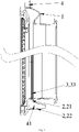
Fig. 1 is a section structural schematic diagram of a window pad of a laundry treatment device according to the invention; -
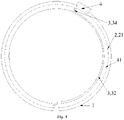
Fig. 2 is a structural schematic diagram of an air guide part of a window pad inEmbodiment 1 of the invention; -
Fig. 3 is a structural schematic diagram of an air guide part of a window pad in Embodiment 2 of the invention; -
Fig. 4 is a structural schematic diagram of an air guide part of a window pad in Embodiment 3 of the invention; and -
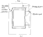
Fig. 5 is a structural schematic diagram of a laundry treatment device inEmbodiment 4 of the invention. - In the drawings: 1, window pad; 2, groove; 21, groove opening; 22, groove bottom; 3, air guide part;31, sealing strip; 32, barrier strip; 33, corrugated structure; 34, shielding part; 4, drying air port; and 41, air channel.
- It should be noted that these drawings and written description are not intended to limit the scope of the present invention in any way, but rather to illustrate the concept of the present invention by reference to specific embodiments for those skilled in the art.
- To make the objectives, technical solutions, and advantages of embodiments of the present invention clearer, the technical solutions in the embodiments will be clearly and completely described below with reference to the accompanying drawings in the embodiments of the present invention. The following embodiments are used to describe the present invention but not to limit the scope of the present invention.
- In the description of the invention, it should be noted that the orientation or position relationship indicated by terms such as "upper", "lower", "front", "rear", "left", "right", "vertical", "inner", "outer" and the like is the orientation or position relationship shown in the drawings, only for the convenience of describing the invention and simplifying the description, rather than indicating or implying that the device or element referred to must have a specific orientation and be constructed and operated in a specific orientation, and therefore cannot be understood as a limitation of the present invention.
- In the description of the present invention, it should be noted that the terms "install", "connected" and "connect" should be understood in a broad sense unless otherwise specified and defined. For example, it can be fixed connection, detachable connection or integrated connection; it can be mechanical connection or electrical connection; and it can be direct connection or indirect connection through an intermediate medium. For those of ordinary skill in the art, the specific meanings of the above-mentioned terms in the present invention can be understood in specific situations.
- As shown in
Figs. 1-5 , the invention provides a window pad of a laundry treatment device, wherein part of a groove in a circumferential direction of the window pad is covered with an air guide part to form an air channel for guiding drying air to the position where there are residual water and foam. Through the structure provided by the invention, the ventilation quantity is increased, and foam and residual water accumulated in the groove at the bottom of the window pad can be eliminated in a short time, and thus, the window pad is suitable for promotion and use. - In this embodiment, provided is a window pad of a laundry treatment device, wherein a drying
air port 4 of the laundry treatment device is formed in a groove 2 formed by wrinkles of awindow pad 1, and an air guide part 3 covering the groove 2 is configured to extend from the dryingair port 4 to the bottom of thewindow pad 1 to form anair channel 41 for guiding drying air to at the bottom of the groove 2. - In this embodiment, the window pad is vertically arranged on the front portion of the laundry treatment device, a groove structure formed by wrinkles is formed in a circumferential direction of the window pad. Due to the fact that a width of an opening of the groove is small and the opening of the groove is arranged towards a center axis of the window pad, the opening of the groove located at the bottom of the window pad is arranged upwards, and residual water and foam are often accumulated in the groove after washing is finished. If treatment on the residual water and foam is not performed for a long time, dirt accumulated in the groove is difficult to clean, and peculiar smell is generated in a washing drum. According to part of the solutions in the prior art, a drying air port is formed in the groove, but due to the existence of the opening of the groove, drying air can directly enter in washing drum through the opening, and residual water accumulated in the groove at the bottom cannot be forcefully blow-dried. In this regard, the air guide part partially covering the groove is designed on the basis of the groove of the window pad, so that the air guide part and the groove jointly define the air channel capable of guiding drying air, and it is achieved to powerful dry of the bottom of the groove. In addition, due to the fact that the air guide part covering part of the groove is adopted, after the bottom of the groove is blow-dried by drying air, the space in the washing drum can be blow-dried continuously due to the fact that the drying air is not blocked by the air guide part continuously.
- In this embodiment, a groove opening 21 and the air guide part 3 are integrally formed from the drying
air port 4 to the bottom of thewindow pad 1 to form theair channel 41 which is closed in a circumferential direction. - In this embodiment, the air guide part and the two sides of the groove opening can be integrally formed to form the air channel which is closed in the circumferential direction. Due to the fact that the closed air channel can bear a large pressure, a drying air speed can be increased, and it is achieved to powerful blow ad dry the bottom of the groove.
- In this embodiment, the air guide part 3 includes a corrugated structure 33 which is of a concave-convex shape in a radial direction of the
window pad 1. The corrugated structure 33 is arranged on one side, facing the groove 2, of the air guide part 3. - In this embodiment, the corrugated structure is arranged on one side, facing the groove, of the air guide part, so that the air pressure of drying air in the air channel is further improved, and residual water and foam in the air channel and at the outlet of the air channel are forcefully blow-dried.
- In this embodiment, a section of the corrugated structure 33 of the air guide part 3 in an axial direction of the
window pad 1 is corrugated. - In this embodiment, the section of the corrugated structure in the axial direction of the window pad is corrugated, namely, the corrugated structure includes a plurality of convex ribs and grooves which are arranged in the circumferential direction of the window pad and are alternately arranged, and the extension directions of the convex ribs and the grooves are consistent with the air outlet direction of drying air, so that the guiding effect on the drying air is enhanced.
- In this embodiment, one end, close to the bottom of the
window pad 1, of the air guide part 3 is bent towards a groove bottom 22. The dryingair port 4 is formed in the groove 2 close to the top of thewindow pad 1. One end, close to the dryingair port 4, of the air guide part 3 is bent towards the dryingair port 4. The one end, close to the dryingair port 4, of the air guide part 3 is provided with a shielding part 34 bent towards the dryingair port 4, and the shielding part 34 is arranged on the side of the dryingair port 4 opposite to the air inlet direction. - In this embodiment, the part, close to the groove at the bottom, of the air guide part is bent towards the groove bottom, so that the inner diameter of the air channel at the outlet is reduced, the pressure of drying air at the outlet is increased, and residual water and foam at the outlet are forcefully blow-dried. The drying air port is arranged close to the top of the window pad, and air is discharged from the bottom of the window pad through the air channel, so that water can be prevented from splashing from the air port when the window pad is sprayed; meanwhile, it is beneficial to increase the air inlet amount, and air drying of the window pad is accelerated.
- In this embodiment, one end, close to the drying air port, of the air guide part is bent towards the groove to form the shielding part. The shielding part is arranged on the side of the drying air port opposite to the air inlet direction so as to guide all the drying air into the air channel. The drying air enters the inner space of the washing drum to perform blow-drying after passing through the air channel to blow-dry the bottom of the groove.
- In this embodiment, the air guide part 3 is a sealing strip 31 integrally formed with the two sides of the groove opening 21 of the
window pad 1. The sealing strip 31 is configured to extend downwards from the dryingair port 4 to the bottom of thewindow pad 1 and extend into the groove 2 at a position close to the dryingair port 4. The sealing strip 31 is configured to extend into the groove 2 on side of the dryingair port 4 opposite to the air inlet direction to form a shielding part 34, and the shielding part 34 and the groove 2 at the bottom of thewindow pad 1 are arranged in a sealed mode. - In this embodiment, the air guide part and the window pad are integrally formed, that is, the air guide part is the sealing strip integrally formed with the two sides of the groove opening of the window pad. The sealing strip is bent and extends into the groove at a position close to the drying air port. The part, bent and extending into the groove, of the sealing strip forms a shielding part so that drying air can be completely guided into the air channel. Therefore, the shielding part is connected with the bottom of the groove in a sealed mode at the moment. One side, facing the axis of the window pad, of the sealing strip is flush with the two sides of the groove opening of the window pad, which can be understood as that the sealing strip is arranged in the groove in a hidden mode.
- The difference between this embodiment and the
embodiment 1 is as follows. - In this embodiment, the air guide part 3 includes a corrugated structure 33 which is of a concave-convex shape in a radial direction of the
window pad 1. - In this embodiment, the corrugated structure is arranged on the two faces, facing the groove and the axis of the window pad, of the air guide part respectively, so that the surface of the air guide part becomes uneven, and drying air blowing through the air guide part is promoted to generate a turbulent flow to spread over the space in the groove and the space in the washing drum. The corrugated structure can also increase the tension on the surface of the foam attached to the corrugated structure, and the foam is promoted to be broken.
- In this embodiment, one end, close to the bottom of the
window pad 1, of the air guide part 3 is bent towards the groove bottom 22. The dryingair port 4 is formed in the groove 2 close to the top of thewindow pad 1. One end, close to the dryingair port 4, of the air guide part 3 is bent towards the dryingair port 4. The one end, close to the dryingair port 4, of the air guide part 3 is bent and extends to the dryingair port 4, and drying air is separated through the air guide part 3. - In this embodiment, the air guide part has a certain thickness. One end, close to the drying air port, of the air guide part is bent on the middle of the drying air port, so the drying air is separated by the end of the air guide part, part of the drying air flows into the air channel to blow-dry the groove at the bottom, and the rest of drying air which does not flow into the air channel enters in the washing drum along the opening of the groove of the window pad and the corrugated structure of the air guide part.
- In this embodiment, the air guide part 3 is a sealing strip 31 integrally formed with the two sides of the groove opening 21 of the
window pad 1, and the sealing strip 31 is configured to extend downwards from the dryingair port 4 to the bottom of thewindow pad 1 and extend into the groove 2 at a position close to the dryingair port 4. - In this embodiment, the air guide part and the window pad are integrally formed, that is, the air guide part is the sealing strip integrally formed with the two sides of the groove opening of the window pad. The sealing strip is bent and extends into the groove at a position close to the drying air port. One end, close to the drying air port, of the sealing strip is bent on the middle of the drying air port, so the end of the sealing strip can separate the drying air.
- Other implementation modes of this embodiment are the same as those in
Embodiment 1. - The difference between this embodiment and the
embodiment 1 is as follows. - In this embodiment, the
window pad 1 is provided with the air guide part 3 which extends from the dryingair port 4 to the bottom of thewindow pad 1 and is in lap joint above the groove opening 21 to form thesemi-closed air channel 41. - In this embodiment, in consideration of the fact that a new mold needs to be adopted for manufacturing a window pad with a partially-closed groove and the cost is increased, the invention further provides another air guide part structure which is in lap joint above the groove opening. The air guide part is in non-sealed connection with the groove. The air guide part can be made of material different from that of the window pad, and the air guide parts with different specifications can be selected according to window pad structures with different sizes, so that the flexibility is improved in use. In addition, according to the solution, the air guide part can be detachably connected with the window pad so as to cope with different use modes.
- In this embodiment, the air guide part 3 is a barrier strip 32 which is in lap joint with the two sides of the groove opening 21 of the
window pad 1. The barrier strip 32 is configured to extend downwards from the dryingair port 4 to the bottom of thewindow pad 1 and is connected with the groove bottom 22 through the shielding part 34 at a position close to the dryingair port 4. A corrugated structure 33 embedded into the groove opening 21 is arranged in the middle of one side, facing the groove 2, of the barrier strip 32, and the two sides of the corrugated structure 33 are planes which are in lap joint with the two sides of the groove opening 21 of thewindow pad 1. - In this embodiment, the air guide part is the barrier strip which is in lap joint above the groove opening, and the barrier strip is configured to extend into the groove at the position close to the drying air port. The part, bent and extending into the groove, of the barrier strip forms a shielding part so that drying air can be completely guided into the air channel. Therefore, the shielding part is connected with the bottom of the groove at the moment. A corrugated structure is arranged on one side, facing the groove, of the barrier strip, and planes which are in lap joint with the window pad are formed on the two sides of the corrugated structure of the barrier strip. In this embodiment, the corrugated structure is in interference fit with the two side walls of the groove, so that the barrier strip is clamped to the groove, and the connection firmness is improved. One side, facing the axis of the window pad, of the barrier strip protrudes out of the two sides of the groove opening of the window pad. It can be understood that the whole barrier strip covers the groove.
- In this embodiment, a connecting piece connected with the shielding part 34 is arranged on the side of the drying
air port 4 opposite to the air inlet direction for allowing a user to mount or dismount the barrier strip 32. - In this embodiment, the air guide part is detachably connected with the connecting piece through the shielding part. Mounting and dismounting can be achieved in various connecting modes, for example, the connecting piece can be arranged to be of a pin structure protruding out of the groove bottom, and the shielding part is arranged to include a hole capable of being connected with the pin structure in an inserted mode. And mounting and dismounting of the air guide part and the connecting piece can be realized through insertion and extraction (not shown in the figure).
- Other implementation modes of this embodiment are the same as those in
Embodiment 1. - This embodiment provides a laundry treatment device, including the window pad of any one of the embodiments 1-3. The laundry treatment device has the functions of washing, drying and the like and is selected from one or a combination of a washing machine, a laundry dryer or a washing and drying machine. By taking a drum washing machine with a drying function as an example, a fan is arranged in an area above a washing drum and is downwards connected to a drying air port of a groove at the top of a window pad through an air pipe. Drying air is sequentially blown into the groove of the window pad along with an air channel and in the washing drum or is simultaneously blown into the groove of the window pad and the washing drum, and then the drying air is exhausted through an air outlet formed in the rear side of the washing drum. And a foam anti-overflow structure is also arranged at the air outlet.
- The above description is only preferred embodiments of the present invention, and is not intended to limit the present invention in any way. Although the present invention has been disclosed as above in the preferred embodiments, it is not intended to limit the present invention. Any technician familiar with this patent can make some changes or modifications to equivalent embodiments with equivalent changes by using the above-mentioned suggestive technical contents without departing from the scope of the technical solution of the present invention. However, any simple amendments, equivalent changes and modifications made to the above embodiments according to the technical essence of the present invention without departing from the contents of the technical solution of the present invention are still within the scope of the solution of the present invention.
Claims (10)
- A window pad of a laundry treatment device, comprising, a groove (2) formed by wrinkles of a window pad (1) in which a drying air port (4) of a laundry treatment device is formed in the groove (2), and an air guide part (3) extending from the drying air port (4) to a bottom of the window pad (1) to cover the groove (2) to form an air channel (41) for guiding drying air to the groove (2) at the bottom.
- The window pad of the laundry treatment device according to claim 1, wherein, a groove opening (21) and the air guide part (3) are in integral to form the air channel (41) from the drying air port (4) to the bottom of the window pad (1) the air channel (41) is closed in a circumferential direction.
- The window pad of the laundry treatment device according to claim 1, wherein, the window pad (1) is provided with the air guide part (3) extending from the drying air port (4) to the bottom of the window pad (1) and being in lap joint above the groove opening (21) to form the semi-closed air channel (41).
- The window pad of the laundry treatment device according to claim 1, wherein, the air guide part (3) comprises a corrugated structure (33) being of a concave-convex shape in a radial direction of the window pad (1);
preferably, the corrugated structure (33) is arranged on one side, facing the groove (2), of the air guide part (3). - The window pad of the laundry treatment device according to claim 4, wherein, a cross section of the corrugated structure (33) of the air guide part (3) is corrugated in an axial direction of the window pad (1).
- The window pad of the laundry treatment device according to any one of claims 1-5, wherein, one end, close to the bottom of the window pad (1), of the air guide part (3) is bent towards a groove bottom (22); the drying air port (4) is formed in the groove (2) close to the top of the window pad (1), and one end, close to the drying air port (4), of the air guide part (3) is bent towards the drying air port (4);preferably, one end, close to the drying air port (4), of the air guide part (3) is bent and extends to the drying air port (4), and drying air is separated through the air guide part (3);more preferably, one end, close to the drying air port (4), of the air guide part (3) is provided with a shielding part (34) bent towards the drying air port (4), and the shielding part (34) is arranged on the side of the drying air port (4) opposite to an air inlet direction.
- The window pad of the laundry treatment device according to claim 6, wherein, the air guide part (3) is a sealing strip (31) integrally formed with the two sides of the groove opening (21) of the window pad (1), and the sealing strip (31) extends downwards from the drying air port (4) to the bottom of the window pad (1) and extends into the groove (2) at a position close to the drying air port (4);
preferably, the sealing strip (31) extends into the groove (2) at the side of the drying air port (4) opposite to the air inlet direction to form the shielding part (34), and the shielding part (34) and the groove (2) at the top of the window pad (1) are arranged in a sealed mode. - The window pad of the laundry treatment device according to claim 6, wherein, the air guide part (3) is a barrier strip (32) which is in lap joint with t the two sides of the groove opening (21) of the window pad (1), and the barrier strip (32) extends downwards from the drying air port (4) to the bottom of the window pad (1) and is connected with the groove bottom (22) through the shielding part (34) at a position close to the drying air port (4);preferably, a corrugated structure (33) is arranged in the middle of one side, facing the groove (2), of the barrier strip (32), and is embedded into the groove opening (21), andthe two sides of the corrugated structure (33) are planes which are in lap joint with the two sides of the groove opening (21) of the window pad (1).
- The window pad of the laundry treatment device according to claim 8, wherein, a connecting piece connected with the shielding part (34) is arranged on the side of the drying air port (4) opposite to the air inlet direction for allowing a user to mount or dismount the barrier strip (32).
- A laundry treatment device, comprising the window pad according to any one of claims 1-9.
Applications Claiming Priority (2)
| Application Number | Priority Date | Filing Date | Title |
|---|---|---|---|
| CN202010051986.0A CN113215777B (en) | 2020-01-17 | 2020-01-17 | Window pad of a clothes treatment device and clothes treatment device |
| PCT/CN2020/140603 WO2021143509A1 (en) | 2020-01-17 | 2020-12-29 | Window seal for laundry treatment device, and laundry treatment device |
Publications (2)
| Publication Number | Publication Date |
|---|---|
| EP4092175A1 true EP4092175A1 (en) | 2022-11-23 |
| EP4092175A4 EP4092175A4 (en) | 2023-07-12 |
Family
ID=76863549
Family Applications (1)
| Application Number | Title | Priority Date | Filing Date |
|---|---|---|---|
| EP20913996.3A Pending EP4092175A4 (en) | 2020-01-17 | 2020-12-29 | WINDOW SEAL FOR LINEN TREATMENT APPLIANCE AND LINEN TREATMENT DEVICE |
Country Status (4)
| Country | Link |
|---|---|
| EP (1) | EP4092175A4 (en) |
| JP (1) | JP7518174B2 (en) |
| CN (1) | CN113215777B (en) |
| WO (1) | WO2021143509A1 (en) |
Families Citing this family (8)
| Publication number | Priority date | Publication date | Assignee | Title |
|---|---|---|---|---|
| CN114717819A (en) * | 2021-01-04 | 2022-07-08 | 博西华电器(江苏)有限公司 | Door sealing ring and washing and drying machine with same |
| WO2023005495A1 (en) * | 2021-07-28 | 2023-02-02 | 青岛海尔洗涤电器有限公司 | Washing and drying integrated device |
| CN115700303B (en) * | 2021-07-28 | 2025-12-09 | 青岛海尔洗涤电器有限公司 | Laundry appliance |
| CN115679638B (en) * | 2021-07-28 | 2026-02-24 | 青岛海尔洗涤电器有限公司 | Laundry appliance |
| CN115679639A (en) * | 2021-07-28 | 2023-02-03 | 青岛海尔洗涤电器有限公司 | Laundry appliance |
| CN115700304B (en) * | 2021-07-28 | 2025-11-25 | 青岛海尔洗涤电器有限公司 | laundry equipment |
| CN115992433B (en) | 2021-10-20 | 2026-01-09 | 佛山海尔滚筒洗衣机有限公司 | Air supply system for washing equipment and washing equipment thereof |
| CN116024787B (en) * | 2021-10-26 | 2026-02-24 | 青岛海尔洗涤电器有限公司 | Microbubble shower nozzle and washing equipment |
Family Cites Families (19)
| Publication number | Priority date | Publication date | Assignee | Title |
|---|---|---|---|---|
| ES432739A1 (en) * | 1974-11-30 | 1976-12-01 | Marchiselli Tognoli | Washing machine |
| JPS5913300Y2 (en) * | 1979-05-15 | 1984-04-20 | 日産自動車株式会社 | Internal combustion engine intake path device |
| US4315815A (en) * | 1980-06-30 | 1982-02-16 | Kerr-Mcgee Refining Corporation | Process for separating bituminous materials and recovering solvent |
| JP3560791B2 (en) * | 1997-11-04 | 2004-09-02 | シャープ株式会社 | Drum type washing machine and method for mounting door packing of drum type drying washing machine |
| JP4167457B2 (en) * | 2002-07-23 | 2008-10-15 | 北越工業株式会社 | Oil-cooled compressor receiver tank |
| JP2008125832A (en) * | 2006-11-21 | 2008-06-05 | Sanyo Electric Co Ltd | Laundry apparatus |
| US8109121B2 (en) * | 2007-09-13 | 2012-02-07 | Lg Electronics Inc. | Drum type washing machine with gasket drain |
| WO2009083396A1 (en) * | 2007-12-31 | 2009-07-09 | Arcelik Anonim Sirketi | A washing machine |
| JP5325001B2 (en) * | 2009-04-15 | 2013-10-23 | 日立アプライアンス株式会社 | Laundry dryer and dryer |
| CN105193337B (en) * | 2015-11-05 | 2017-07-25 | 台州市浙恒机械科技有限公司 | The quick hair dryer of human body |
| CN108118503A (en) * | 2016-11-30 | 2018-06-05 | 博西华电器(江苏)有限公司 | Dryer |
| KR20180136141A (en) * | 2017-06-14 | 2018-12-24 | 주식회사 대우전자 | Wall mounted drum type washing machine |
| CN107238135B (en) * | 2017-07-21 | 2023-11-28 | 安徽扬子空调股份有限公司 | Dry fan coil |
| CN109306597B (en) * | 2017-07-26 | 2022-04-08 | 青岛海尔洗涤电器有限公司 | Drying method and structure of laundry processing device and laundry processing device |
| CN109837709B (en) * | 2017-11-24 | 2022-08-02 | 青岛海尔洗涤电器有限公司 | Drum washing machine |
| JP6781510B2 (en) * | 2017-11-30 | 2020-11-04 | 日立グローバルライフソリューションズ株式会社 | Washing and drying machine |
| CN108677460A (en) * | 2018-06-26 | 2018-10-19 | 刘雪松 | A kind of sealing ring with degerming functions |
| CN108660687A (en) * | 2018-06-26 | 2018-10-16 | 刘雪松 | A kind of sealing ring for roller washing machine |
| CN109838416A (en) * | 2019-04-15 | 2019-06-04 | 周小余 | A kind of centrifugal fan |
-
2020
- 2020-01-17 CN CN202010051986.0A patent/CN113215777B/en active Active
- 2020-12-29 WO PCT/CN2020/140603 patent/WO2021143509A1/en not_active Ceased
- 2020-12-29 EP EP20913996.3A patent/EP4092175A4/en active Pending
- 2020-12-29 JP JP2022543495A patent/JP7518174B2/en active Active
Also Published As
| Publication number | Publication date |
|---|---|
| WO2021143509A1 (en) | 2021-07-22 |
| JP7518174B2 (en) | 2024-07-17 |
| EP4092175A4 (en) | 2023-07-12 |
| JP2023512927A (en) | 2023-03-30 |
| CN113215777A (en) | 2021-08-06 |
| CN113215777B (en) | 2022-12-09 |
Similar Documents
| Publication | Publication Date | Title |
|---|---|---|
| JP7518174B2 (en) | Window packing for clothing processing device and clothing processing device | |
| JP7012930B2 (en) | Drum type washing machine | |
| CN110318237B (en) | Clothes processing equipment | |
| CN101324022A (en) | Drainage device and washing machine with the same | |
| CN205329383U (en) | Door seals subassembly and all -in -one washer dryer | |
| CN114687106B (en) | Outer tube assembly and garment handling equipment having the outer tube assembly | |
| CN112080912B (en) | A clothing treatment device | |
| CN115216939B (en) | Clothes treatment equipment | |
| CN222119713U (en) | Clothes processing equipment | |
| CN221276118U (en) | Outer drum and clothing processing device | |
| JP6387529B2 (en) | Hand dryer | |
| CN220088823U (en) | Hair drier | |
| KR100484409B1 (en) | A vacuum cleaner | |
| CN215887583U (en) | Washing and drying integrated machine | |
| CN112301626B (en) | Clothes processing equipment | |
| CN113215795A (en) | Outer Drum Assembly and Washer Dryer | |
| CN219527090U (en) | laundry equipment | |
| CN223813640U (en) | Fan assembly and clothes treatment equipment | |
| CN223936863U (en) | Lint filter device and laundry treatment apparatus including the same | |
| CN218989679U (en) | Washing and drying integrated machine condenser and washing and drying integrated machine | |
| CN220952611U (en) | Air outlet structure, drying module and clothes treatment device | |
| CN224193366U (en) | Hand drier with water guiding function | |
| CN111020984B (en) | Clothes treating apparatus | |
| CN112301662B (en) | Air supply device and clothes treatment equipment | |
| CN120830231A (en) | Clothes processing equipment |
Legal Events
| Date | Code | Title | Description |
|---|---|---|---|
| STAA | Information on the status of an ep patent application or granted ep patent |
Free format text: STATUS: THE INTERNATIONAL PUBLICATION HAS BEEN MADE |
|
| PUAI | Public reference made under article 153(3) epc to a published international application that has entered the european phase |
Free format text: ORIGINAL CODE: 0009012 |
|
| STAA | Information on the status of an ep patent application or granted ep patent |
Free format text: STATUS: REQUEST FOR EXAMINATION WAS MADE |
|
| 17P | Request for examination filed |
Effective date: 20220815 |
|
| AK | Designated contracting states |
Kind code of ref document: A1 Designated state(s): AL AT BE BG CH CY CZ DE DK EE ES FI FR GB GR HR HU IE IS IT LI LT LU LV MC MK MT NL NO PL PT RO RS SE SI SK SM TR |
|
| DAV | Request for validation of the european patent (deleted) | ||
| DAX | Request for extension of the european patent (deleted) | ||
| A4 | Supplementary search report drawn up and despatched |
Effective date: 20230609 |
|
| RIC1 | Information provided on ipc code assigned before grant |
Ipc: D06F 58/20 20060101ALI20230602BHEP Ipc: D06F 58/02 20060101ALI20230602BHEP Ipc: D06F 37/26 20060101ALI20230602BHEP Ipc: D06F 39/00 20200101ALI20230602BHEP Ipc: D06F 37/04 20060101ALI20230602BHEP Ipc: D06F 25/00 20060101AFI20230602BHEP |
|
| STAA | Information on the status of an ep patent application or granted ep patent |
Free format text: STATUS: EXAMINATION IS IN PROGRESS |
|
| 17Q | First examination report despatched |
Effective date: 20250219 |