EP4091902A1 - Height adjustment device - Google Patents
Height adjustment device Download PDFInfo
- Publication number
- EP4091902A1 EP4091902A1 EP21741073.7A EP21741073A EP4091902A1 EP 4091902 A1 EP4091902 A1 EP 4091902A1 EP 21741073 A EP21741073 A EP 21741073A EP 4091902 A1 EP4091902 A1 EP 4091902A1
- Authority
- EP
- European Patent Office
- Prior art keywords
- valve
- case
- valve rod
- flow passage
- flow rate
- Prior art date
- Legal status (The legal status is an assumption and is not a legal conclusion. Google has not performed a legal analysis and makes no representation as to the accuracy of the status listed.)
- Pending
Links
Images





Classifications
-
- B—PERFORMING OPERATIONS; TRANSPORTING
- B61—RAILWAYS
- B61F—RAIL VEHICLE SUSPENSIONS, e.g. UNDERFRAMES, BOGIES OR ARRANGEMENTS OF WHEEL AXLES; RAIL VEHICLES FOR USE ON TRACKS OF DIFFERENT WIDTH; PREVENTING DERAILING OF RAIL VEHICLES; WHEEL GUARDS, OBSTRUCTION REMOVERS OR THE LIKE FOR RAIL VEHICLES
- B61F5/00—Constructional details of bogies; Connections between bogies and vehicle underframes; Arrangements or devices for adjusting or allowing self-adjustment of wheel axles or bogies when rounding curves
- B61F5/02—Arrangements permitting limited transverse relative movements between vehicle underframe or bolster and bogie; Connections between underframes and bogies
- B61F5/04—Bolster supports or mountings
- B61F5/10—Bolster supports or mountings incorporating fluid springs
-
- B—PERFORMING OPERATIONS; TRANSPORTING
- B61—RAILWAYS
- B61F—RAIL VEHICLE SUSPENSIONS, e.g. UNDERFRAMES, BOGIES OR ARRANGEMENTS OF WHEEL AXLES; RAIL VEHICLES FOR USE ON TRACKS OF DIFFERENT WIDTH; PREVENTING DERAILING OF RAIL VEHICLES; WHEEL GUARDS, OBSTRUCTION REMOVERS OR THE LIKE FOR RAIL VEHICLES
- B61F5/00—Constructional details of bogies; Connections between bogies and vehicle underframes; Arrangements or devices for adjusting or allowing self-adjustment of wheel axles or bogies when rounding curves
- B61F5/02—Arrangements permitting limited transverse relative movements between vehicle underframe or bolster and bogie; Connections between underframes and bogies
- B61F5/22—Guiding of the vehicle underframes with respect to the bogies
-
- F—MECHANICAL ENGINEERING; LIGHTING; HEATING; WEAPONS; BLASTING
- F16—ENGINEERING ELEMENTS AND UNITS; GENERAL MEASURES FOR PRODUCING AND MAINTAINING EFFECTIVE FUNCTIONING OF MACHINES OR INSTALLATIONS; THERMAL INSULATION IN GENERAL
- F16K—VALVES; TAPS; COCKS; ACTUATING-FLOATS; DEVICES FOR VENTING OR AERATING
- F16K31/00—Actuating devices; Operating means; Releasing devices
- F16K31/44—Mechanical actuating means
- F16K31/52—Mechanical actuating means with crank, eccentric, or cam
- F16K31/524—Mechanical actuating means with crank, eccentric, or cam with a cam
- F16K31/52408—Mechanical actuating means with crank, eccentric, or cam with a cam comprising a lift valve
-
- Y—GENERAL TAGGING OF NEW TECHNOLOGICAL DEVELOPMENTS; GENERAL TAGGING OF CROSS-SECTIONAL TECHNOLOGIES SPANNING OVER SEVERAL SECTIONS OF THE IPC; TECHNICAL SUBJECTS COVERED BY FORMER USPC CROSS-REFERENCE ART COLLECTIONS [XRACs] AND DIGESTS
- Y02—TECHNOLOGIES OR APPLICATIONS FOR MITIGATION OR ADAPTATION AGAINST CLIMATE CHANGE
- Y02T—CLIMATE CHANGE MITIGATION TECHNOLOGIES RELATED TO TRANSPORTATION
- Y02T30/00—Transportation of goods or passengers via railways, e.g. energy recovery or reducing air resistance
Definitions
- leveling valves for railway trains (hereinafter referred to as “leveling valves”) provided in a passage of fluid between a fluid source (a compressor) and a fluid actuation apparatus (an air spring) and configured to adjust the height of a vehicle body relative to a bogie.
- a leveling valve a valve apparatus
- air is supplied to or exhausted from a fluid actuation apparatus when an intake valve rod or an exhaust valve rod moves forward/rearward according to a relative displacement of a vehicle body to a bogie.
- This leveling valve is categorized into the LV4 type having a dead zone and a time lag in the JRIS standards (the Japan Association of Rolling Stock Industries Standards).
- leveling valves categorized into the LV7 type have an extremely low flow rate zone around the neutral position of an actuation arm.
- the guide portion is disposed at the position different from the first fluid control portion, and therefore a change in the extremely low flow rate characteristic of the leveling apparatus can be prevented over a long period of time.
- the exhaust valve 81 When the exhaust valve 81 is opened to establish the communication between the air spring 3 and the exhaust port 12, the air stored in the air spring 3 is exhausted into the atmosphere and the air spring 3 compresses.
- the horizontal lever 7 moves pivotally about the driven shaft 11 in the counterclockwise direction in Fig. 1 , and the driven shaft 11 rotates in the counterclockwise direction in Fig. 1 in conjunction with the horizontal lever 7.
- the exhaust valve 81 is closed to block the communication between the air spring 3 and the exhaust port 12 (the atmosphere).
- the leveling valve 1 selectively brings the air spring 3 into communication with the compressor 2 (the fluid source) or the exhaust port 12 (the atmosphere) according to the rotational direction of the driven shaft 11 (the pivotal movement direction of the horizontal lever 7).
- An annular flow passage 29 is provided between the proximal portion (the left end portion) of the small-diameter shaft portion 28 of the case 24 and the large-diameter hole portion 25 of the case hole 23. Further, an annular flow passage 30 is provided between the small-diameter shaft portion 28 of the case 24 and the small-diameter hole portion 26 of the case hole 23. The annular flow passage 30 is formed by an annular groove formed on the small-diameter hole portion 26. The annular flow passage 30 is sealed by a seal ring 31 and a seal ring 32 provided on the small-diameter shaft portion 28 of the case 24. On the other hand, the annular flow passage 29 is sealed by the seal ring 32 and a seal ring 33. The seal ring 33 is compressed between the case hole 23 and the case 24. The case 24 is fixed to the housing 13 using a nut 36.
- a stepped recessed portion 48 is provided on the end surface of the case 24 on the outer side (the "left side” in Fig. 2 ).
- the end of the third hole portion 46 on the outer side is opened to the bottom portion of the stepped recessed portion 48.
- An intake-side port portion 49 is mounted in the stepped recessed portion 48.
- the third hole portion 46 is sealed to the atmosphere by a seal ring 50 provided on the intake-side port portion 49.
- the intake-side port portion 49 is prevented from being detached off from the case 24 by a stop ring 51 attached on the step portion of the stepped recessed portion 48.
- One end side of a passage 4A (refer to Fig.
- the annular flow passage 89 is sealed by the seal ring 92 and a seal ring 93.
- the seal ring 93 is compressed between the case hole 83 and the case 84.
- the case 84 is fixed to the housing 13 using a nut 96.
- the exhaust-side port portion 109 is in communication with the atmosphere via a passage (not illustrated) provided to the housing 13.
- the valve body 115 is a component separated off from the valve rod 97, and is formed into a stepped columnar shape including a large-diameter portion 116 and a small-diameter portion 117.
- the large-diameter portion 116 and the small-diameter portion 117 of the valve body 115 are inserted in the third hole portion 106 of the case 84 and the second hole portion 104 of the case 84, respectively.
- An annular seated portion 118 is embedded between the large-diameter portion 116 and the small-diameter portion 117.
- the seated portion 118 faces the seat portion 114.
- the valve body 115 is biased in a valve-closing direction (the "leftward direction in Fig.
- valve spring 119 provided between the valve body 115 and the exhaust-side port portion 109.
- an elastic member is used as the seated portion 118.
- annular extremely small flow passage 131 is formed between the small-diameter portion 117 and the second hole portion 104 with the small-diameter portion 117 of the valve body 115 inserted in the second hole portion 104.
- the end surface of the boss portion 128 is in abutment with the end surface of the small-diameter portion 117 of the valve body 115. Due to that, an annular flow passage 129 is formed around the outer periphery of the boss portion 128. The flow passage 129 is in communication with the flow passage 127.
- the intake valve 21 is in a valve-closed state illustrated in Fig. 3 .
- the valve body 55 (the seated portion 58) is seated on the seat portion 54 and the valve portion 53 is closed.
- a flow of the air (fluid) between the annular flow passage 29 and the annular flow passage 30 is blocked, and the vehicle height is kept at the reference height.
- a space of approximately 1 mm is formed between the actuation arm 14 and the valve rod 37, and a dead zone on the intake side can be adjusted by adjusting this space.
- Fig. 4 illustrates the state of the intake valve 21 when the leveling valve 1 exhibits a flow rate characteristic in an extremely low flow rate zone (hereinafter referred to as a "slightly opened state").
- the intake valve 21 is in the slightly opened state, the valve body 55 is pressed in by the valve rod 37 (the boss portion 68 of the guide portion 61) in the valve-opening direction and the seated portion 58 is separated from the seat portion 54, by which the valve portion 53 is opened.
- the compressed air introduced from the intake-side port portion 49 flows into the annular flow passage 30 by passing through the annular flow passage 29, the plurality of passages 47, the annular flow passage 72 on the outer periphery of the large-diameter portion 56 of the valve body 55, the annular flow passage 73 between the large-diameter portion 56 of the valve body 55 and the bottom surface of the third hole portion 46 in the axial direction (the "horizontal direction" in Fig.
- the extremely small flow passage 71 the annular flow passage 69 between the small-diameter portion 57 of the valve body 55 and the guide portion 61 in the axial direction, the flow passages 67 extending through the guide portion 61, and the plurality of passages 45.
- the air flows through the annular extremely small flow passage 71 (an orifice) between the small-diameter portion 57 of the valve body 55 and the second hole portion 44 of the case 24, and therefore the leveling valve 1 exhibits the flow rate characteristic in the extremely low flow rate zone.
- Fig. 5 illustrates the state of the intake valve 21 when the leveling valve 1 exhibits a flow rate characteristic in a normal flow rate zone (hereinafter referred to as a "full opened state").
- a full opened state the exit of the small-diameter portion 57 of the valve body 55 from the second hole portion 44 leads to elimination of the extremely small flow passage 71 (refer to Fig.
- valve rod and the flow rate control portion are integrally configured in the conventional LV-7 leveling valves, and therefore the flow passage area may increase and the extremely low flow rate characteristic may change if the flow rate control portion is unevenly worn due to a force in a gouging direction that is applied to the valve rod.
- the valve body 55 (the first flow rate control portion) is configured separately from the valve rod 37, and the extremely small flow passage 71, which controls the flow rate in the flow passage establishing the communication between the compressor 2 (the fluid source) and the air spring 3 (the fluid actuation apparatus), is formed by inserting the small-diameter portion 57 of the valve body 55 in the second hole portion 44 of the case 24.
- the leveling valve 1 is configured in such a manner that the valve rod 37 is guided in the axial direction (the movement direction) by placing the guide portion 61 provided on the valve portion 53 side (the proximal end side) of the valve rod 37 into sliding contact with the case 24.
- the valve body 55 (the first flow rate control portion) is not subjected to a force in the gouging direction that is applied to the valve rod 37, and therefore the extremely low flow rate characteristic of the leveling valve 1 (a leveling apparatus) does not change even when the guide portion 61 is unevenly worn by receiving the force on the valve rod 37 in the gouging direction.
- the change in the extremely low flow rate characteristic of the leveling valve 1 can be prevented over a long period of time.
- the first embodiment can be configured in the following manner.
- the flow passage area of the annular flow passage 72 should have a large area compared to the flow passage area of the extremely small flow passage 71 to set the extremely low flow rate zone for the extremely low flow rate characteristic (the orifice characteristic) around the neutral position of the actuation arm 14. Therefore, in the first embodiment, a large space (the annular flow passage 72) is generated between the large-diameter portion 56 and the third hole portion 46 compared to the space (the extremely small flow passage 71) between the small-diameter portion 57 and the second hole portion 44, and the valve body 55 may be tilted with respect to the axis of the case 24 as a result thereof.
- the leveling valve 1 can be configured in such a manner that the space between the large-diameter portion 56 and the third hole portion 46 is narrowed to a smaller size than the space between the small-diameter portion 57 and the second hole portion 44, and, further, a flow passage establishing the communication between the plurality of passages 47 and the annular flow passage 73 is formed by providing a plurality of grooves (for example, refer to the "grooves 66" in Fig. 6 ) around the large-diameter portion 56.
- the flow passages 67 axially extending through the guide portion 61 can be formed by providing a plurality of holes 76 axially extending through the guide portion 61 around the shaft hole 64 of the guide portion 61.
- the flow passages 67 axially extending through the guide portion 61 can be formed by providing a plurality of cutouts 77 radially extending from the shaft hole 64 of the guide portion 61.
- the flow passages 67 axially extending through the guide portion 61 can be formed by providing axially extending grooves 78 on the inner peripheral surface of the second hole portion 44 of the case 24.
- the valve body 55 (the first flow rate control portion) is configured separately from the valve rod 37, and the extremely small flow passage 71, which controls the flow rate in the flow passage establishing the communication between the compressor 2 (the fluid source) and the air spring 3 (the fluid actuation apparatus), is formed between the valve body 55 and the case 24 by inserting the small-diameter portion 57 of the valve body 55 in the second hole portion 44 of the case 24.
- valve rod 37 and a valve body 145 (the first flow rate control portion) of a first valve portion 142 are integrally configured, and an extremely small flow passage 151, which controls the flow rate of the flow passage establishing the communication between the compressor 2 and the air spring 3, is formed between a valve body 155 and the valve rod 37 by inserting the valve rod 37 in a shaft hole 156 (a radially inner portion) of the valve body 155 (a second flow rate control portion) of a second valve portion 143.
- the first valve portion 142 includes an annular seat portion 146 and the valve body 145 (the first flow rate control portion).
- the seat portion 146 is provided on the circumferential edge of the opening of the valve body 155 of the second valve portion 143 on the outer side of the shaft hole 156 (the "left side” in Fig. 11 ).
- the valve body 145 is in abutment with the seat portion 146 separably.
- the valve body 145 is provided at the proximal end portion (the "left-side end portion” in Fig. 11 ) of the valve rod 37, and is inserted in the third hole portion 46 of the case 24.
- An annular seated portion 147 is embedded in the end surface of the valve body 145 on the inner side (the "right side” in Fig. 11 ).
- the seated portion 147 faces the seat portion 146.
- the valve body 145 and thus the valve rod 37 are biased by the valve spring 59 provided between the intake-side port portion 49 (refer to Fig. 2 ) and the valve body 145 in a valve-closing direction (the "rightward direction" in Fig. 11 ).
- the second valve portion 143 includes an annular seat portion 157 and the valve body 155 (the second flow rate control portion).
- the seat portion 157 is provided on the circumferential edge of the opening of the second hole portion 44 of the case 24.
- the valve body 155 is in abutment with the seat portion 157 separably.
- the valve body 155 is cylindrically formed, and is inserted in the third hole portion 46 of the case 24.
- the valve body 155 is disposed axially between the valve body 145 of the first valve portion 142 and the bottom surface of the third hole portion 46, and an annular seated portion 158 is embedded in the end surface of the valve body 155 on the inner side (the "right side" in Fig. 11 ) that faces the seat portion 157.
- the valve body 155 of the second valve portion 143 has a smaller outer diameter than the valve body 145 of the first valve portion 142, and an annular flow passage 159 is provided around the outer periphery of the valve body 155.
- a cylindrical guide portion 161 is inserted in the second hole portion 44 of the case 24.
- the valve rod 37 is fixed in a shaft hole 162 of the guide portion 161 by, for example, being press-fitted therein.
- the flow passages 67 (refer to Fig. 10 ) axially extending through the guide portion 161 are formed by providing the axially extending grooves 78 (refer to Fig. 10 ) on the inner peripheral surface of the second hole portion 44 of the case 24.
- the exhaust valve according to the second embodiment has a similar basic structure to the intake valve 141. Therefore, the detailed description of the exhaust valve will be omitted here for the purpose of simplifying the description of the specification.
- the intake valve 141 is in the valve-closed state illustrated in Fig. 11 .
- the valve body 145 (the seated portion 147) is seated on the seat portion 146, by which the first valve portion 142 is closed.
- the valve body 155 (the seated portion 158) is seated on the seat portion 157, by which the second valve portion 143 is closed.
- the flow of the air (fluid) between the annular flow passage 29 and the annular flow passage 30 is blocked, and the vehicle height is kept at the reference height.
- a space of approximately 1 mm is formed between the actuation arm 14 and the valve rod 37, and a dead zone on the intake side can be adjusted by adjusting this space.
- Fig. 12 illustrates the slightly opened state of the intake valve 141 when the leveling valve 1 exhibits the extremely low flow rate characteristic.
- the valve body 145 (the first flow rate control portion) integrated with the valve rod 37 moves in the valve-opening direction and the seated portion 147 is separated from the seat portion 146, by which the first valve portion 142 is opened.
- the compressed air introduced from the intake-side port portion 49 flows into the annular flow passage 30 by passing through the annular flow passage 29, the plurality of passages 47, the extremely small flow passage 151, the flow passages 67 (refer to Fig. 10 ) extending through the guide portion 161, and the plurality of passages 45.
- the air flows through the annular extremely small flow passage 151 (an orifice) between the shaft hole 156 of the valve body 155 and the valve rod 37, and therefore the leveling valve 1 exhibits the extremely low flow rate characteristic.
- the valve body 155 is subjected to a force due to the compressed air in the valve-closing direction (the "rightward direction" in Fig. 12 ), and therefore the second valve portion 143 is kept closed.
- FIG. 13 illustrates the full opened state of the intake valve 141.
- the valve body 155 of the second valve portion 143 is pressed in by the guide portion 161 in the valve-opening direction, and is located at a valve-opening position.
- the compressed air introduced from the intake-side port portion 49 (refer to Fig.
- the leveling valve 1 Because the extremely small flow passage 151 is not eliminated even with the intake valve 141 in the full opened state, precisely speaking, the leveling valve 1 exhibits a flow rate characteristic combined with the extremely low flow rate characteristic.
- the second embodiment can bring about functions and advantageous effects similar to the above-described first embodiment.
- the second embodiment can be configured in the following manner.
- a larger space should be generated between the valve body 155 and the third hole portion 46 than the space between the valve body 155 and the valve rod 37 (the extremely small flow passage 151) to secure the flow passage area of the annular flow passage 159 with the intake valve 141 in the full opened state (refer to Fig. 13 ), and therefore the valve body 155 may be tilted with respect to the axis of the case 24 as a result thereof.
- the leveling valve 1 can be configured in such a manner that the space between the valve body 155 and the third hole portion 46 is narrowed to a smaller size than the space between the valve body 155 and the valve rod 37, and, further, a flow passage establishing the communication between the pluralities of passages 47 and flow passages 45 is formed by providing a plurality of grooves (for example, refer to the "grooves 66" in Fig. 6 ) around the valve body 155.
- the present invention shall not be limited to the above-described embodiments, and includes various modifications.
- the above-described embodiments have been described in detail to facilitate a better understanding of the present invention, and the present invention shall not necessarily be limited to the configuration including all of the described features.
- a part of the configuration of some embodiment can be replaced with the configuration of another embodiment.
- some embodiment can also be implemented with a configuration of another embodiment added to the configuration of this embodiment.
- each embodiment can also be implemented with another configuration added, deleted, or replaced with respect to a part of the configuration of this embodiment.
Landscapes
- Engineering & Computer Science (AREA)
- Mechanical Engineering (AREA)
- General Engineering & Computer Science (AREA)
- Lift Valve (AREA)
- Mechanically-Actuated Valves (AREA)
Abstract
Description
- The present invention relates to an automatic leveling apparatus for a railway train.
- There are known leveling valves for railway trains (hereinafter referred to as "leveling valves") provided in a passage of fluid between a fluid source (a compressor) and a fluid actuation apparatus (an air spring) and configured to adjust the height of a vehicle body relative to a bogie. According to a leveling valve (a valve apparatus) disclosed in PTL 1, air is supplied to or exhausted from a fluid actuation apparatus when an intake valve rod or an exhaust valve rod moves forward/rearward according to a relative displacement of a vehicle body to a bogie. This leveling valve is categorized into the LV4 type having a dead zone and a time lag in the JRIS standards (the Japan Association of Rolling Stock Industries Standards). On the other hand, leveling valves categorized into the LV7 type have an extremely low flow rate zone around the neutral position of an actuation arm.
- PTL 1:
Japanese Patent Application Public Disclosure No. 2012-31932 - In the LV4-type and LV7-type leveling valves, a force is applied to the valve rod in a gouging direction due to contact of the rotating actuation arm and the horizontally moving valve rod. If a flow rate control portion is unevenly worn, an extremely low flow rate characteristic (an orifice characteristic) changes especially in the LV7-type leveling valves.
- One of objects of the present invention is to provide a leveling apparatus capable of preventing a change in an extremely low flow rate characteristic over a long period of time.
- According to one aspect of the present invention, a leveling apparatus is provided in a passage of fluid between a fluid source and a fluid actuation apparatus and configured to adjust a height of a vehicle body relative to a bogie. The leveling apparatus includes an actuation arm configured to move pivotally according to a relative displacement of the vehicle body to the bogie, a case including a flow passage establishing communication between the fluid source or the atmosphere and the fluid actuation apparatus, a valve rod having a distal end protruding from one end side of the case into abutment with the actuation arm and configured to move relative to the case according to the pivotal movement of the actuation arm, a valve portion contained in the case and configured to open the flow passage due to the movement of the valve rod, a first flow rate control portion provided between the valve portion and the valve rod and configured to control a flow rate in the flow passage according to a movement position of the valve rod, and a guide portion provided to the valve rod. The guide portion is disposed at a position different from the first flow rate control portion in a movement direction of the valve rod and placed in sliding contact with an inside of the case.
- According to the one aspect of the present invention, the guide portion is disposed at the position different from the first fluid control portion, and therefore a change in the extremely low flow rate characteristic of the leveling apparatus can be prevented over a long period of time.
-
-
Fig. 1 illustrates a first embodiment, and illustrates a general concept of a system including a leveling valve. -
Fig. 2 illustrates the first embodiment, and is a front view of the leveling valve with a part thereof cross-sectionally illustrated. -
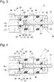
Fig. 3 illustrates the first embodiment, and is a cross-sectional view of an intake valve when the valve is closed. -
Fig. 4 illustrates the first embodiment, and is a cross-sectional view of the intake valve at the time of an extremely low flow rate characteristic. -
Fig. 5 illustrates the first embodiment, and is a cross-sectional view of the intake valve when the valve is opened. -
Fig. 6 is a front view of a guide portion used in the first embodiment. -
Fig. 7 illustrates the first embodiment, and is a cross-sectional view of an exhaust valve when the valve is closed. -
Fig. 8 illustrates another embodiment of the guide portion. -
Fig. 9 illustrates another embodiment of the guide portion. -
Fig. 10 illustrates another embodiment of the guide portion. -
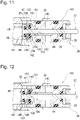
Fig. 11 illustrates a second embodiment, and is a cross-sectional view of an intake valve when the valve is closed. -
Fig. 12 illustrates the second embodiment, and is a cross-sectional view of the intake valve at the time of the extremely low flow rate characteristic. -
Fig. 13 illustrates the second embodiment, and is a cross-sectional view of the intake valve when the valve is opened. - (First Embodiment) A first embodiment of the present invention will be described with reference to the accompanying drawings.
- The vertical direction in
Figs. 1 and2 will be referred to as a vertical direction of the present leveling valve 1 (a leveling apparatus) for convenience. - As illustrated in
Fig. 1 , the leveling valve 1 is a so-called leveling valve for a railway train provided in apassage 4 of air (fluid) between a compressor 2 (a fluid source) and an air spring 3 (a fluid actuation apparatus), and configured to automatically adjust the height of avehicle body 6 relative to a bogie (flatcar) 5. The leveling valve 1 includes a drivenshaft 11 located at the center of ahousing 13 and coupled with thebogie 5 via ahorizontal lever 7 and alinkage rod 8. - Referring to
Figs. 1 and2 , in the leveling valve 1, when the vehicle height changes, i.e., theair spring 3 compresses or extends to cause thevehicle body 6 to be displaced relative to thebogie 5, this displacement is converted into a rotational motion of the drivenshaft 11. At this time, when the vehicle height is lowered, i.e., theair spring 3 compresses, thehorizontal lever 7 moves pivotally about the drivenshaft 11 from a neutral position (refer toFig. 1 ) in the counterclockwise direction inFig. 1 . Due to that, the drivenshaft 11 rotates in the counterclockwise direction inFig, 1 in conjunction with thehorizontal lever 7. As a result, anintake valve 21 is opened to establish communication through thepassage 4 between the compressor 2 and theair spring 3. - When the
intake valve 21 is opened to establish the communication through thepassage 4, compressed air is supplied from the compressor 2 to theair spring 3 and theair spring 3 extends as a result thereof. When theair spring 3 extends, thehorizontal lever 7 moves pivotally about the drivenshaft 11 in the clockwise direction inFig. 1 , and the drivenshaft 11 rotates in the clockwise direction inFig. 1 in conjunction with thehorizontal lever 7. When the vehicle height reaches a reference height, i.e., thehorizontal lever 7 returns to the neutral position (refer toFig. 1 ), theintake valve 21 is closed to block the communication through thepassage 4. - On the other hand, when the vehicle height is raised, i.e., the
air spring 3 extends, thehorizontal lever 7 moves pivotally about the drivenshaft 11 from the neutral position (refer toFig. 1 ) in the clockwise direction inFig. 1 . Due to that, the drivenshaft 11 rotates in the clockwise direction inFig, 1 in conjunction with thehorizontal lever 7. As a result, anexhaust valve 81 is opened to establish communication between theair spring 3 and an exhaust port 12 (refer to 1). - When the
exhaust valve 81 is opened to establish the communication between theair spring 3 and theexhaust port 12, the air stored in theair spring 3 is exhausted into the atmosphere and theair spring 3 compresses. When theair spring 3 compresses, thehorizontal lever 7 moves pivotally about the drivenshaft 11 in the counterclockwise direction inFig. 1 , and the drivenshaft 11 rotates in the counterclockwise direction inFig. 1 in conjunction with thehorizontal lever 7. When the vehicle height reaches the reference height, i.e., thehorizontal lever 7 returns to the neutral position (refer toFig. 1 ), theexhaust valve 81 is closed to block the communication between theair spring 3 and the exhaust port 12 (the atmosphere). - In this manner, when the
horizontal lever 7 moves pivotally about the drivenshaft 11 according to the relative displacement of thevehicle body 6 to thebogie 5, the drivenshaft 11 rotates in the clockwise direction or the counterclockwise direction in conjunction with thehorizontal lever 7. The leveling valve 1 selectively brings theair spring 3 into communication with the compressor 2 (the fluid source) or the exhaust port 12 (the atmosphere) according to the rotational direction of the driven shaft 11 (the pivotal movement direction of the horizontal lever 7). As a result, the relative displacement of thevehicle body 6 to thebogie 5 is automatically adjusted, and the vehicle height is kept at the reference height. - As illustrated in
Fig. 2 , the drivenshaft 11 is provided rotatably about an axis in thehousing 13 fixed to thevehicle body 6. The drivenshaft 11 is disposed along the width direction of the vehicle body 6 (perpendicularly to the horizontal lever 7). Anactuation arm 14 and atorsion spring 15 are provided at one end portion of the driven shaft 11 (the end portion thereof on the outer side of the vehicle body 6). When theactuation arm 14 moves pivotally about the axis of the drivenshaft 11 to an intake side (the "counterclockwise direction" inFig. 2 ) or an exhaust side (the "clockwise direction" inFig. 2 ), thetorsion spring 15 generates a biasing force (a spring force) for returning theactuation arm 14 to a neutral position (refer toFig. 2 ). Acheck valve 17 is provided at the center of the upper portion of thehousing 13. - The
intake valve 21 and theexhaust valve 81 are provided on one side (the "left side" inFig. 2 ) and the opposite side (the "right side" inFig. 2 ) in the upper portion of thehousing 13, respectively. Theintake valve 21 includes acase 24 attached in acase hole 23 provided on a one-side surface 22 of thehousing 13. Thecase hole 23 includes a large-diameter hole portion 25 and a small-diameter hole portion 26. The large-diameter hole portion 25 is opened to the one-side surface 22 of thehousing 13. The small-diameter hole portion 26 is opened to anoil chamber 16 at the center of thehousing 13. A small-diameter shaft portion 28 of thecase 24 is fitted in the small-diameter hole portion 26 of thecase hole 23. On the other hand, a large-diameter shaft portion 27 of thecase 24 is fixed in the large-diameter hole portion 25 of thecase hole 23. - An
annular flow passage 29 is provided between the proximal portion (the left end portion) of the small-diameter shaft portion 28 of thecase 24 and the large-diameter hole portion 25 of thecase hole 23. Further, anannular flow passage 30 is provided between the small-diameter shaft portion 28 of thecase 24 and the small-diameter hole portion 26 of thecase hole 23. Theannular flow passage 30 is formed by an annular groove formed on the small-diameter hole portion 26. Theannular flow passage 30 is sealed by aseal ring 31 and aseal ring 32 provided on the small-diameter shaft portion 28 of thecase 24. On the other hand, theannular flow passage 29 is sealed by theseal ring 32 and aseal ring 33. Theseal ring 33 is compressed between thecase hole 23 and thecase 24. Thecase 24 is fixed to thehousing 13 using anut 36. - A
valve rod 37 is provided in a hollow portion of thecase 24. Thevalve rod 37 is coaxial with thecase hole 23 and thecase 24. An axially (horizontally) intermediate portion of thevalve rod 37 is slidably fitted in afirst hole portion 38 of thecase 24. A recessedportion 40 is provided on the end surface of thecase 24 on the inner side (the "right side" inFig. 2 ). The end of thefirst hole portion 38 on the inner side is opened to the bottom portion of the recessedportion 40. Awasher 41 and anut 42 are provided in the recessedportion 40. Thefirst hole portion 38 of thecase 24 is sealed to theoil chamber 16 by aseal ring 43 provided in an annular groove of the bottom surface of the recessedportion 40. - The
valve rod 37 is inserted through thewasher 41 and thenut 42, and an end portion 39 (the distal end) thereof on the inner side (the "right side" inFig. 2 ) protrudes from the end surface (one end side) of thecase 24 on the inner side to theoil chamber 16. The spherical surface of theend portion 39 on the inner side is in abutment with theactuation arm 14 and thevalve rod 37 axially moves in conjunction with the pivotal movement of theactuation arm 14. Asecond hole portion 44 is provided in the hollow portion of thecase 24. The end of thefirst hole portion 38 on the outer side (the "left side" inFig. 2 ) is opened to the bottom portion of thesecond hole portion 44. Thesecond hole portion 44 is in communication with theannular flow passage 30 via a plurality of passages 45 ("two passages" illustrated inFig. 2 ) provided on the small-diameter shaft portion 28 of thecase 24. - A
third hole portion 46 is provided in the hollow portion of thecase 24. The end of thesecond hole portion 44 on the outer side (the "left side" inFig. 2 ) is opened to thethird hole portion 46. Thethird hole portion 46 is in communication with theannular flow passage 29 via a plurality of passages 47 ("two passages" illustrated inFig. 2 ) provided on the small-diameter shaft portion 28 of thecase 24. The hole diameter of the hollow portion of thecase 24 increases in the order of thefirst hole portion 38, thesecond hole portion 44, and thethird hole portion 46. - A stepped recessed
portion 48 is provided on the end surface of thecase 24 on the outer side (the "left side" inFig. 2 ). The end of thethird hole portion 46 on the outer side is opened to the bottom portion of the stepped recessedportion 48. An intake-side port portion 49 is mounted in the stepped recessedportion 48. Thethird hole portion 46 is sealed to the atmosphere by aseal ring 50 provided on the intake-side port portion 49. The intake-side port portion 49 is prevented from being detached off from thecase 24 by astop ring 51 attached on the step portion of the stepped recessedportion 48. One end side of apassage 4A (refer toFig. 1 ) is connected to the compressor 2 (the fluid source), and the opposite end side of thepassage 4A is connected to the intake-side port portion 49. Further, the intake-side port portion 49 is in communication with theannular flow passage 29 via a passage (not illustrated) provided to thehousing 13. - A
valve portion 53 is provided in theintake valve 21. Thevalve portion 53 establishes or blocks the communication between the compressor 2 (the fluid source) and the air spring 3 (the fluid actuation apparatus) according to a movement of thevalve rod 37. Thevalve portion 53 includes anannular seat portion 54 and a valve body 55 (a first flow rate control portion). Theannular seat portion 54 is provided on the circumferential edge of the opening of thesecond hole portion 44 on the outer side (the "left side" inFig. 2 ). Thevalve body 55 is in abutment with theseat portion 54 separably therefrom. Theseat portion 54 has a protrusion shape protruding to the outer side with respect to the bottom surface of thethird hole portion 46. - The
valve body 55 is a component separated off from thevalve rod 37, and is formed into a stepped columnar shape including a large-diameter portion 56 and a small-diameter portion 57. The large-diameter portion 56 and the small-diameter portion 57 of thevalve body 55 are inserted in thethird hole portion 46 of thecase 24 and thesecond hole portion 44 of thecase 24, respectively. An annular seatedportion 58 is embedded between the large-diameter portion 56 and the small-diameter portion 57. The seatedportion 58 faces theseat portion 54. Thevalve body 55 is biased in a valve-closing direction (the "rightward direction inFig. 2 ) by avalve spring 59 provided between thevalve body 55 and the intake-side port portion 49. For example, an elastic member is used as the seatedportion 58. Further, an annular extremely small flow passage 71 (refer toFig. 4 ) is formed between the small-diameter portion 57 and thesecond hole portion 44 with the small-diameter portion 57 of thevalve body 55 inserted in thesecond hole portion 44. - Referring to
Figs. 3 and6 , theintake valve 21 includes aguide portion 61 provided at the end portion (the proximal end) of thevalve rod 37 on the outer side (the "left side" inFig. 3 ). Theguide portion 61 is formed into a sleeve-like shape, and an outerperipheral surface 62 thereof (refer toFig. 6 ) is guided by thesecond hole portion 44 of thecase 24 in the axial direction (the "horizontal direction" inFig. 3 ). In other words, theguide portion 61 is inserted in thesecond hole portion 44 of thecase 24. Ashaft hole 64 is formed through theguide portion 61. A small-diameter shaft portion 63 formed at the end portion of thevalve rod 37 on the outer side is press-fitted in theshaft hole 64. Theguide portion 61 is axially positioned relative to thevalve rod 37 due to abutment of the end surface thereof on the inner side (the "right side" inFig. 3 ) against a steppedportion 65 of thevalve rod 37. - A plurality of ("three" in the first embodiment) grooves 66 (refer to
Fig. 6 ) is provided on the outerperipheral surface 62 of theguide portion 61. Thegrooves 66 are arranged at circumferential equal intervals. Thegrooves 66 extend on theguide portion 61 in the axial direction (the "horizontal direction" inFig. 3 ). Due to that, a plurality offlow passages 67 is formed between thecase 24 and theguide portion 61. Theflow passages 67 establish communication between theannular flow passage 29 and theannular flow passage 30. Aboss portion 68 coaxial with theguide portion 61 is formed on the end surface of theguide portion 61 on the outer side (the "left side" inFig. 3 ). The end surface of theboss portion 68 is in abutment with the end surface of the small-diameter portion 57 of thevalve body 55. Due to that, anannular flow passage 69 is formed around the outer periphery of theboss portion 68. Theflow passage 69 is in communication with theflow passages 67. - On the other hand, the
exhaust valve 81 includes acase 84 attached to acase hole 83 provided on an opposite-side surface 82 of thehousing 13. Thecase hole 83 includes a large-diameter hole portion 85 and a small-diameter hole portion 86. The large-diameter hole portion 85 is opened to the opposite-side surface 82 of thehousing 13. The small-diameter hole portion 86 is opened to theoil chamber 16 at the center of thehousing 13. A small-diameter shaft portion 88 of thecase 84 is fitted in the small-diameter hole portion 86 of thecase hole 83. On the other hand, a large-diameter shaft portion 87 of thecase 84 is fixed in the large-diameter hole portion 85 of thecase hole 83. - An
annular flow passage 89 is provided between the proximal portion (the right end portion) of the small-diameter shaft portion 88 of thecase 84 and the large-diameter hole portion 85 of thecase hole 83. Further, anannular flow passage 90 is provided between the small-diameter shaft portion 88 of thecase 84 and the small-diameter hole portion 86 of thecase hole 83. Theannular flow passage 90 is formed by an annular groove formed on the small-diameter hole portion 86. Theannular flow passage 90 is sealed by aseal ring 91 and aseal ring 92 provided on the small-diameter shaft portion 88 of thecase 84. On the other hand, theannular flow passage 89 is sealed by theseal ring 92 and a seal ring 93. The seal ring 93 is compressed between thecase hole 83 and thecase 84. Thecase 84 is fixed to thehousing 13 using anut 96. - A
valve rod 97 is provided in a hollow portion of thecase 84. Thevalve rod 97 is coaxial with thecase hole 83 and thecase 84. An axially (horizontally) intermediate portion of thevalve rod 97 is slidably fitted in afirst hole portion 98 of thecase 84. A recessedportion 100 is provided on the end surface of thecase 84 on the inner side (the "left side" inFig. 2 ). The end of thefirst hole portion 98 on the inner side is opened to the bottom portion of the recessedportion 100. Awasher 101 and anut 102 are mounted in the recessedportion 100. Thefirst hole portion 98 of thecase 84 is sealed to theoil chamber 16 by aseal ring 103 provided in an annular groove of the bottom surface of the recessedportion 100. - The
valve rod 97 is inserted through thewasher 101 and thenut 102, and an end portion 99 (the distal end) thereof on the inner side (the "left side" inFig. 2 ) protrudes from the end surface (one end side) of thecase 84 on the inner side to theoil chamber 16. The spherical surface of theend portion 99 on the inner side is in abutment with theactuation arm 14 and thevalve rod 97 axially moves in conjunction with the pivotal movement of theactuation arm 14. Asecond hole portion 104 is provided in the hollow portion of thecase 84. The end of thefirst hole portion 98 on the outer side (the "right side" inFig. 2 ) is opened to the bottom portion of thesecond hole portion 104. Thesecond hole portion 104 is in communication with theannular passage 90 via a plurality of passages 105 ("two passages" illustrated inFig. 2 ) provided on the small-diameter shaft portion 88 of thecase 84. - A
third hole portion 106 is provided in the hollow portion of thecase 84. The end of thesecond hole portion 104 on the outer side (the "right side" inFig. 2 ) is opened to thethird hole portion 106. Thethird hole portion 106 is in communication with theannular flow passage 89 via a plurality of passages 107 ("two passages" illustrated inFig. 2 ) provided on the small-diameter shaft portion 88 of thecase 84. The hole diameter of the hollow portion of thecase 84 increases in the order of thefirst hole portion 98, thesecond hole portion 104, and thethird hole portion 106. - A stepped recessed
portion 108 is provided on the end surface of thecase 84 on the outer side (the "right side" inFig. 2 ). The end of thethird hole portion 106 on the outer side is opened to the bottom portion of the stepped recessedportion 108. An exhaust-side port portion 109 is mounted in the stepped recessedportion 108. Thethird hole portion 106 is sealed to the atmosphere by aseal ring 110 provided on the exhaust-side port portion 109. The exhaust-side port portion 109 is prevented from being detached off from thecase 84 by astop ring 111 attached on the step portion of the stepped recessedportion 108. One end side of apassage 4B (refer toFig. 1 ) is connected to the air spring 3 (the fluid actuation apparatus), and the opposite end side of thepassage 4B is connected to the exhaust-side port portion 109. Further, the exhaust-side port portion 109 is in communication with the atmosphere via a passage (not illustrated) provided to thehousing 13. - Referring to
Figs. 2 and7 , avalve portion 113 is provided in theexhaust valve 81. Thevalve portion 113 establishes or blocks communication between the air spring 3 (the fluid actuation apparatus) and the atmosphere according to a movement of thevalve rod 97. Thevalve portion 113 includes anannular seat portion 114 and avalve body 115. Theseat portion 114 is provided on the circumferential edge of the opening of thesecond hole portion 104 on the outer side (the "right side" inFig. 2 ). Thevalve body 115 is in abutment with theseat portion 114 separably therefrom. Theseat portion 114 has a protrusion shape protruding to the outer side with respect to the bottom surface of thethird hole portion 106. - The
valve body 115 is a component separated off from thevalve rod 97, and is formed into a stepped columnar shape including a large-diameter portion 116 and a small-diameter portion 117. The large-diameter portion 116 and the small-diameter portion 117 of thevalve body 115 are inserted in thethird hole portion 106 of thecase 84 and thesecond hole portion 104 of thecase 84, respectively. An annular seated portion 118 is embedded between the large-diameter portion 116 and the small-diameter portion 117. The seated portion 118 faces theseat portion 114. Thevalve body 115 is biased in a valve-closing direction (the "leftward direction inFig. 2 ) by avalve spring 119 provided between thevalve body 115 and the exhaust-side port portion 109. For example, an elastic member is used as the seated portion 118. Further, an annular extremelysmall flow passage 131 is formed between the small-diameter portion 117 and thesecond hole portion 104 with the small-diameter portion 117 of thevalve body 115 inserted in thesecond hole portion 104. - The
exhaust valve 81 includes aguide portion 121 provided at the end portion (the proximal end) of thevalve rod 97 on the outer side (the "right side" inFig. 2 ). Theguide portion 121 is formed into a sleeve-like shape, and an outerperipheral surface 122 thereof is guided by thesecond hole portion 104 of thecase 84 in the axial direction (the "horizontal direction" inFig. 7 ). In other words, theguide portion 121 is inserted in thesecond hole portion 104 of thecase 84. A shaft hole 124 is formed through theguide portion 121. A small-diameter shaft portion 123 formed at the end portion of thevalve rod 97 on the outer side is press-fitted in the shaft hole 124. Theguide portion 121 is axially positioned relative to thevalve rod 97 due to abutment of the end surface thereof on the inner side (the "left side" inFig. 7 ) against a stepped portion 125 of thevalve rod 97. - A plurality of ("three" in the first embodiment) grooves 126 (refer to
Fig. 7 ) is provided on the outerperipheral surface 122 of theguide portion 121. The grooves 126 are arranged at circumferential equal intervals. The grooves 126 extend on theguide portion 121 in the axial direction (the "horizontal direction" inFig. 3 ). Due to that, a plurality of flow passages 127 is formed between thecase 84 and theguide portion 121. The flow passages 127 establish communication between theannular flow passage 89 and theannular flow passage 90. Aboss portion 128 coaxial with theguide portion 121 is formed on the end surface of theguide portion 121 on the outer side (the "right side" inFig. 7 ). The end surface of theboss portion 128 is in abutment with the end surface of the small-diameter portion 117 of thevalve body 115. Due to that, anannular flow passage 129 is formed around the outer periphery of theboss portion 128. Theflow passage 129 is in communication with the flow passage 127. - Next, the operation of the above-described
intake valve 21 of the leveling valve 1 will be described. The operation of theexhaust valve 81 is similar to the operation of theintake valve 21, and therefore the detailed description thereof will be omitted herein for the purpose of simplifying the description of the specification. - When the
actuation arm 14 is located at the neutral position (refer toFig. 2 ), theintake valve 21 is in a valve-closed state illustrated inFig. 3 . At this time, the valve body 55 (the seated portion 58) is seated on theseat portion 54 and thevalve portion 53 is closed. As a result, a flow of the air (fluid) between theannular flow passage 29 and theannular flow passage 30 is blocked, and the vehicle height is kept at the reference height. When theactuation arm 14 is located at the neutral position, a space of approximately 1 mm is formed between theactuation arm 14 and thevalve rod 37, and a dead zone on the intake side can be adjusted by adjusting this space. - When the
actuation arm 14 moves pivotally from the neutral position in the counterclockwise direction, thevalve rod 37 is pressed in by theactuation arm 14 in a valve-opening direction (the "leftward direction" inFig. 2 ).Fig. 4 illustrates the state of theintake valve 21 when the leveling valve 1 exhibits a flow rate characteristic in an extremely low flow rate zone (hereinafter referred to as a "slightly opened state"). When theintake valve 21 is in the slightly opened state, thevalve body 55 is pressed in by the valve rod 37 (theboss portion 68 of the guide portion 61) in the valve-opening direction and the seatedportion 58 is separated from theseat portion 54, by which thevalve portion 53 is opened. - Due to that, the compressed air introduced from the intake-side port portion 49 (refer to
Fig. 2 ) flows into theannular flow passage 30 by passing through theannular flow passage 29, the plurality ofpassages 47, theannular flow passage 72 on the outer periphery of the large-diameter portion 56 of thevalve body 55, theannular flow passage 73 between the large-diameter portion 56 of thevalve body 55 and the bottom surface of thethird hole portion 46 in the axial direction (the "horizontal direction" inFig. 4 ), the extremelysmall flow passage 71, theannular flow passage 69 between the small-diameter portion 57 of thevalve body 55 and theguide portion 61 in the axial direction, theflow passages 67 extending through theguide portion 61, and the plurality ofpassages 45. At this time, the air flows through the annular extremely small flow passage 71 (an orifice) between the small-diameter portion 57 of thevalve body 55 and thesecond hole portion 44 of thecase 24, and therefore the leveling valve 1 exhibits the flow rate characteristic in the extremely low flow rate zone. - When the
actuation arm 14 further moves pivotally in the counterclockwise direction, thevalve rod 37 is further pressed in by the actuation arm 14 (refer toFig. 2 ) in the valve-opening direction.Fig. 5 illustrates the state of theintake valve 21 when the leveling valve 1 exhibits a flow rate characteristic in a normal flow rate zone (hereinafter referred to as a "full opened state"). When theintake valve 21 is in the full opened state, the exit of the small-diameter portion 57 of thevalve body 55 from thesecond hole portion 44 leads to elimination of the extremely small flow passage 71 (refer toFig. 4 ) in the slightly opened state and emergence of anannular flow passage 74 having an unrestricted (non-narrowed) flow passage area between the small-diameter portion 57 of thevalve body 55 and the opening of thesecond hole portion 44. As a result, the compressed air introduced from the intake-side port portion 49 (refer toFig. 2 ) flows into theannular flow passage 30 by passing through theannular flow passage 29, the plurality ofpassages 47, theannular flow passage 73, theannular flow passage 74, theflow passages 67, and the plurality ofpassages 45. - Now, the valve rod and the flow rate control portion are integrally configured in the conventional LV-7 leveling valves, and therefore the flow passage area may increase and the extremely low flow rate characteristic may change if the flow rate control portion is unevenly worn due to a force in a gouging direction that is applied to the valve rod.
- On the other hand, in the first embodiment, the valve body 55 (the first flow rate control portion) is configured separately from the
valve rod 37, and the extremelysmall flow passage 71, which controls the flow rate in the flow passage establishing the communication between the compressor 2 (the fluid source) and the air spring 3 (the fluid actuation apparatus), is formed by inserting the small-diameter portion 57 of thevalve body 55 in thesecond hole portion 44 of thecase 24. Further, in the first embodiment, the leveling valve 1 is configured in such a manner that thevalve rod 37 is guided in the axial direction (the movement direction) by placing theguide portion 61 provided on thevalve portion 53 side (the proximal end side) of thevalve rod 37 into sliding contact with thecase 24. - According to the first embodiment, the valve body 55 (the first flow rate control portion) is not subjected to a force in the gouging direction that is applied to the
valve rod 37, and therefore the extremely low flow rate characteristic of the leveling valve 1 (a leveling apparatus) does not change even when theguide portion 61 is unevenly worn by receiving the force on thevalve rod 37 in the gouging direction. As a result, the change in the extremely low flow rate characteristic of the leveling valve 1 can be prevented over a long period of time. - The first embodiment can be configured in the following manner.
- In the first embodiment, the flow passage area of the
annular flow passage 72 should have a large area compared to the flow passage area of the extremelysmall flow passage 71 to set the extremely low flow rate zone for the extremely low flow rate characteristic (the orifice characteristic) around the neutral position of theactuation arm 14. Therefore, in the first embodiment, a large space (the annular flow passage 72) is generated between the large-diameter portion 56 and thethird hole portion 46 compared to the space (the extremely small flow passage 71) between the small-diameter portion 57 and thesecond hole portion 44, and thevalve body 55 may be tilted with respect to the axis of thecase 24 as a result thereof. In light thereof, the leveling valve 1 can be configured in such a manner that the space between the large-diameter portion 56 and thethird hole portion 46 is narrowed to a smaller size than the space between the small-diameter portion 57 and thesecond hole portion 44, and, further, a flow passage establishing the communication between the plurality ofpassages 47 and theannular flow passage 73 is formed by providing a plurality of grooves (for example, refer to the "grooves 66" inFig. 6 ) around the large-diameter portion 56. - Further, as illustrated in
Fig. 8 , theflow passages 67 axially extending through theguide portion 61 can be formed by providing a plurality ofholes 76 axially extending through theguide portion 61 around theshaft hole 64 of theguide portion 61. - Alternatively, as illustrated in
Fig. 9 , theflow passages 67 axially extending through theguide portion 61 can be formed by providing a plurality ofcutouts 77 radially extending from theshaft hole 64 of theguide portion 61. - Alternatively, as illustrated in
Fig. 10 , theflow passages 67 axially extending through theguide portion 61 can be formed by providing axially extendinggrooves 78 on the inner peripheral surface of thesecond hole portion 44 of thecase 24. - (Second Embodiment) A second embodiment of the present invention will be described with reference to the accompanying drawings.
- The same or equivalent components as or to the first embodiment will be identified by the same names and reference numerals, and the detailed descriptions thereof will be omitted below.
- In the above-described first embodiment, as illustrated in
Fig. 4 , the valve body 55 (the first flow rate control portion) is configured separately from thevalve rod 37, and the extremelysmall flow passage 71, which controls the flow rate in the flow passage establishing the communication between the compressor 2 (the fluid source) and the air spring 3 (the fluid actuation apparatus), is formed between thevalve body 55 and thecase 24 by inserting the small-diameter portion 57 of thevalve body 55 in thesecond hole portion 44 of thecase 24. - On the other hand, in the second embodiment, as illustrated in
Fig. 11 , thevalve rod 37 and a valve body 145 (the first flow rate control portion) of afirst valve portion 142 are integrally configured, and an extremelysmall flow passage 151, which controls the flow rate of the flow passage establishing the communication between the compressor 2 and theair spring 3, is formed between avalve body 155 and thevalve rod 37 by inserting thevalve rod 37 in a shaft hole 156 (a radially inner portion) of the valve body 155 (a second flow rate control portion) of asecond valve portion 143. - The
first valve portion 142 includes anannular seat portion 146 and the valve body 145 (the first flow rate control portion). Theseat portion 146 is provided on the circumferential edge of the opening of thevalve body 155 of thesecond valve portion 143 on the outer side of the shaft hole 156 (the "left side" inFig. 11 ). Thevalve body 145 is in abutment with theseat portion 146 separably. Thevalve body 145 is provided at the proximal end portion (the "left-side end portion" inFig. 11 ) of thevalve rod 37, and is inserted in thethird hole portion 46 of thecase 24. An annular seatedportion 147 is embedded in the end surface of thevalve body 145 on the inner side (the "right side" inFig. 11 ). The seatedportion 147 faces theseat portion 146. Thevalve body 145 and thus thevalve rod 37 are biased by thevalve spring 59 provided between the intake-side port portion 49 (refer toFig. 2 ) and thevalve body 145 in a valve-closing direction (the "rightward direction" inFig. 11 ). - On the other hand, the
second valve portion 143 includes anannular seat portion 157 and the valve body 155 (the second flow rate control portion). Theseat portion 157 is provided on the circumferential edge of the opening of thesecond hole portion 44 of thecase 24. Thevalve body 155 is in abutment with theseat portion 157 separably. Thevalve body 155 is cylindrically formed, and is inserted in thethird hole portion 46 of thecase 24. Thevalve body 155 is disposed axially between thevalve body 145 of thefirst valve portion 142 and the bottom surface of thethird hole portion 46, and an annular seatedportion 158 is embedded in the end surface of thevalve body 155 on the inner side (the "right side" inFig. 11 ) that faces theseat portion 157. Thevalve body 155 of thesecond valve portion 143 has a smaller outer diameter than thevalve body 145 of thefirst valve portion 142, and anannular flow passage 159 is provided around the outer periphery of thevalve body 155. - A
cylindrical guide portion 161 is inserted in thesecond hole portion 44 of thecase 24. Thevalve rod 37 is fixed in ashaft hole 162 of theguide portion 161 by, for example, being press-fitted therein. In the second embodiment, the flow passages 67 (refer toFig. 10 ) axially extending through theguide portion 161 are formed by providing the axially extending grooves 78 (refer toFig. 10 ) on the inner peripheral surface of thesecond hole portion 44 of thecase 24. - The exhaust valve according to the second embodiment has a similar basic structure to the
intake valve 141. Therefore, the detailed description of the exhaust valve will be omitted here for the purpose of simplifying the description of the specification. - In the second embodiment, when the
actuation arm 14 is located at the neutral position (refer toFig. 2 ), theintake valve 141 is in the valve-closed state illustrated inFig. 11 . At this time, the valve body 145 (the seated portion 147) is seated on theseat portion 146, by which thefirst valve portion 142 is closed. On the other hand, the valve body 155 (the seated portion 158) is seated on theseat portion 157, by which thesecond valve portion 143 is closed. As a result, the flow of the air (fluid) between theannular flow passage 29 and theannular flow passage 30 is blocked, and the vehicle height is kept at the reference height. When theactuation arm 14 is located at the neutral position, a space of approximately 1 mm is formed between theactuation arm 14 and thevalve rod 37, and a dead zone on the intake side can be adjusted by adjusting this space. - When the
actuation arm 14 moves pivotally from the neutral position in the counterclockwise direction, thevalve rod 37 is pressed in by theactuation arm 14 in a valve-opening direction (the "leftward direction" inFig. 11). Fig. 12 illustrates the slightly opened state of theintake valve 141 when the leveling valve 1 exhibits the extremely low flow rate characteristic. When theintake valve 141 is in the slightly opened state, the valve body 145 (the first flow rate control portion) integrated with thevalve rod 37 moves in the valve-opening direction and the seatedportion 147 is separated from theseat portion 146, by which thefirst valve portion 142 is opened. - As a result, the compressed air introduced from the intake-side port portion 49 (refer to
Fig. 2 ) flows into theannular flow passage 30 by passing through theannular flow passage 29, the plurality ofpassages 47, the extremelysmall flow passage 151, the flow passages 67 (refer toFig. 10 ) extending through theguide portion 161, and the plurality ofpassages 45. At this time, the air flows through the annular extremely small flow passage 151 (an orifice) between theshaft hole 156 of thevalve body 155 and thevalve rod 37, and therefore the leveling valve 1 exhibits the extremely low flow rate characteristic. Thevalve body 155 is subjected to a force due to the compressed air in the valve-closing direction (the "rightward direction" inFig. 12 ), and therefore thesecond valve portion 143 is kept closed. - When the
actuation arm 14 further moves pivotally in the counterclockwise direction, thevalve rod 37 is further pressed in by theactuation arm 14 in the valve-opening direction.Fig. 13 illustrates the full opened state of theintake valve 141. When theintake valve 141 is in the full opened state, thevalve body 155 of thesecond valve portion 143 is pressed in by theguide portion 161 in the valve-opening direction, and is located at a valve-opening position. At the valve-opening position of thevalve body 155, the compressed air introduced from the intake-side port portion 49 (refer toFig. 2 ) flows into theannular flow passage 30 by passing through theannular flow passage 29, the plurality ofpassages 47, theannular flow passage 159 around the outer periphery of thevalve body 155, the flow passages 67 (refer toFig. 10 ), and the plurality ofpassages 45. Because the extremelysmall flow passage 151 is not eliminated even with theintake valve 141 in the full opened state, precisely speaking, the leveling valve 1 exhibits a flow rate characteristic combined with the extremely low flow rate characteristic. - The second embodiment can bring about functions and advantageous effects similar to the above-described first embodiment.
- The second embodiment can be configured in the following manner.
- In the second embodiment, a larger space should be generated between the
valve body 155 and thethird hole portion 46 than the space between thevalve body 155 and the valve rod 37 (the extremely small flow passage 151) to secure the flow passage area of theannular flow passage 159 with theintake valve 141 in the full opened state (refer toFig. 13 ), and therefore thevalve body 155 may be tilted with respect to the axis of thecase 24 as a result thereof. In light thereof, the leveling valve 1 can be configured in such a manner that the space between thevalve body 155 and thethird hole portion 46 is narrowed to a smaller size than the space between thevalve body 155 and thevalve rod 37, and, further, a flow passage establishing the communication between the pluralities ofpassages 47 and flowpassages 45 is formed by providing a plurality of grooves (for example, refer to the "grooves 66" inFig. 6 ) around thevalve body 155. - The present invention shall not be limited to the above-described embodiments, and includes various modifications. For example, the above-described embodiments have been described in detail to facilitate a better understanding of the present invention, and the present invention shall not necessarily be limited to the configuration including all of the described features. Further, a part of the configuration of some embodiment can be replaced with the configuration of another embodiment. Further, some embodiment can also be implemented with a configuration of another embodiment added to the configuration of this embodiment. Further, each embodiment can also be implemented with another configuration added, deleted, or replaced with respect to a part of the configuration of this embodiment.
- The present application claims priority under the Paris Convention to
Japanese Patent Application No. 2020-004427 filed on January 15, 2020 Japanese Patent Application No. 2020-004427 filed on January 15, 2020 -
- 1
- leveling valve (leveling apparatus)
- 2
- compressor (fluid source)
- 3
- air spring (fluid actuation apparatus)
- 4
- passage
- 5
- bogie
- 6
- vehicle body
- 14
- actuation arm
- 24
- case
- 37
- valve rod
- 53
- valve portion
- 55
- valve body (first flow rate control portion)
- 61
- guide portion
Claims (2)
- A leveling apparatus provided in a passage of fluid between a fluid source and a fluid actuation apparatus and configured to adjust a height of a vehicle body relative to a bogie, the leveling apparatus comprising:an actuation arm configured to move pivotally according to a relative displacement of the vehicle body to the bogie;a case including a flow passage establishing communication between the fluid source or the atmosphere and the fluid actuation apparatus;a valve rod having a distal end protruding from one end side of the case into abutment with the actuation arm and configured to move relative to the case according to the pivotal movement of the actuation arm;a valve portion contained in the case and configured to open the flow passage due to the movement of the valve rod;a first flow rate control portion provided between the valve portion and the valve rod and configured to control a flow rate in the flow passage according to a movement position of the valve rod; anda guide portion provided to the valve rod, the guide portion being disposed at a position different from the first flow rate control portion in a movement direction of the valve rod and placed in sliding contact with an inside of the case.
- The leveling apparatus according to claim 1, further comprising a second flow rate control portion provided between the valve portion and the case, the valve rod being inserted in a radially inner portion of the second flow rate control portion.
Applications Claiming Priority (2)
| Application Number | Priority Date | Filing Date | Title |
|---|---|---|---|
| JP2020004427 | 2020-01-15 | ||
| PCT/JP2021/000459 WO2021145277A1 (en) | 2020-01-15 | 2021-01-08 | Height adjustment device |
Publications (2)
| Publication Number | Publication Date |
|---|---|
| EP4091902A1 true EP4091902A1 (en) | 2022-11-23 |
| EP4091902A4 EP4091902A4 (en) | 2023-06-28 |
Family
ID=76864642
Family Applications (1)
| Application Number | Title | Priority Date | Filing Date |
|---|---|---|---|
| EP21741073.7A Pending EP4091902A4 (en) | 2020-01-15 | 2021-01-08 | Height adjustment device |
Country Status (4)
| Country | Link |
|---|---|
| EP (1) | EP4091902A4 (en) |
| JP (1) | JP7241208B2 (en) |
| CN (1) | CN114929548A (en) |
| WO (1) | WO2021145277A1 (en) |
Family Cites Families (9)
| Publication number | Priority date | Publication date | Assignee | Title |
|---|---|---|---|---|
| JPH02300535A (en) * | 1989-05-11 | 1990-12-12 | Nippon Sharyo Seizo Kaisha Ltd | Differential pressure adjusting device for air spring |
| US7832426B2 (en) * | 2006-09-05 | 2010-11-16 | Fisher Controls International Llc | Parabolic bonnet for three-way valve |
| JP2012031932A (en) * | 2010-07-30 | 2012-02-16 | Hitachi Automotive Systems Ltd | Valve device |
| JP5986941B2 (en) * | 2013-02-28 | 2016-09-06 | Kyb株式会社 | Leveling valve |
| US9777843B2 (en) * | 2014-02-19 | 2017-10-03 | Mitsubishi Heavy Industries Compressor Corporation | Steam valve and steam turbine |
| JP2016075327A (en) * | 2014-10-03 | 2016-05-12 | 株式会社東芝 | Manufacturing method of valve device, and valve device |
| CN104653851A (en) * | 2015-01-22 | 2015-05-27 | 哈尔滨工程大学 | Sea valve capable of saving labor during valve opening |
| US10480667B2 (en) * | 2016-05-18 | 2019-11-19 | Ron J. Gaubert | Storage tank valve |
| JP6810771B2 (en) | 2019-08-08 | 2021-01-06 | ホーチキ株式会社 | Indicator light device |
-
2021
- 2021-01-08 CN CN202180008686.7A patent/CN114929548A/en active Pending
- 2021-01-08 JP JP2021571169A patent/JP7241208B2/en active Active
- 2021-01-08 EP EP21741073.7A patent/EP4091902A4/en active Pending
- 2021-01-08 WO PCT/JP2021/000459 patent/WO2021145277A1/en not_active Ceased
Also Published As
| Publication number | Publication date |
|---|---|
| EP4091902A4 (en) | 2023-06-28 |
| JPWO2021145277A1 (en) | 2021-07-22 |
| CN114929548A (en) | 2022-08-19 |
| JP7241208B2 (en) | 2023-03-16 |
| WO2021145277A1 (en) | 2021-07-22 |
Similar Documents
| Publication | Publication Date | Title |
|---|---|---|
| US10450908B2 (en) | Rocker arm assembly for engine braking | |
| JP5203957B2 (en) | Latch mechanism of dual lift rocker arm and its operation configuration | |
| EP3853450B1 (en) | Improved response time in lost motion valvetrains | |
| JP2018534468A (en) | Rocker arm assembly for engine brake | |
| EP1143120A2 (en) | Valve deactivator assembly for internal combustion engine | |
| US6695578B2 (en) | Bleed valve system for a gas turbine engine | |
| US20250101891A1 (en) | Rocker Arm for Brake with Integrated Hydraulic Capsule | |
| JP2007071207A (en) | Bypass valve for internal combustion engines | |
| JP2004036603A (en) | Lash adjustment device capable of non-operating locking ball | |
| JPH01182581A (en) | Control device for variable displacement compressor | |
| US7493879B2 (en) | Engine valve operating system | |
| KR101847308B1 (en) | Leveling valve | |
| US6953012B2 (en) | Forced opening and closing type valve operating system | |
| US8746279B2 (en) | Pressure control valve | |
| US12577893B2 (en) | Double pressure capsule assembly | |
| JP5869366B2 (en) | Leveling valve | |
| JP2018096460A (en) | Valve | |
| JP6709101B2 (en) | Leveling valve | |
| JP4423225B2 (en) | Tire pressure adjustment valve | |
| JP7241208B2 (en) | Height adjuster | |
| US20250179947A1 (en) | Integrated rocker brake with reset plunger for actuating a single engine valve | |
| WO2003004913B1 (en) | Small bore gate valve | |
| JP2001343082A (en) | Pressure control valve | |
| US12286909B2 (en) | Rocker arm with a reset slider disposed in a lash adjustment assembly | |
| US20180172175A1 (en) | Valve Assembly With Vent Port Between Supply Port and Control Port |
Legal Events
| Date | Code | Title | Description |
|---|---|---|---|
| STAA | Information on the status of an ep patent application or granted ep patent |
Free format text: STATUS: THE INTERNATIONAL PUBLICATION HAS BEEN MADE |
|
| PUAI | Public reference made under article 153(3) epc to a published international application that has entered the european phase |
Free format text: ORIGINAL CODE: 0009012 |
|
| STAA | Information on the status of an ep patent application or granted ep patent |
Free format text: STATUS: REQUEST FOR EXAMINATION WAS MADE |
|
| 17P | Request for examination filed |
Effective date: 20220712 |
|
| AK | Designated contracting states |
Kind code of ref document: A1 Designated state(s): AL AT BE BG CH CY CZ DE DK EE ES FI FR GB GR HR HU IE IS IT LI LT LU LV MC MK MT NL NO PL PT RO RS SE SI SK SM TR |
|
| DAV | Request for validation of the european patent (deleted) | ||
| DAX | Request for extension of the european patent (deleted) | ||
| A4 | Supplementary search report drawn up and despatched |
Effective date: 20230530 |
|
| RIC1 | Information provided on ipc code assigned before grant |
Ipc: F16K 1/32 20060101ALI20230523BHEP Ipc: F16K 1/00 20060101ALI20230523BHEP Ipc: B61F 5/22 20060101ALI20230523BHEP Ipc: B61F 5/10 20060101AFI20230523BHEP |
|
| STAA | Information on the status of an ep patent application or granted ep patent |
Free format text: STATUS: EXAMINATION IS IN PROGRESS |
|
| 17Q | First examination report despatched |
Effective date: 20250528 |
|
| RAP3 | Party data changed (applicant data changed or rights of an application transferred) |
Owner name: ASTEMO, LTD. |