EP4091851A1 - Vehicle power transmission system, and vehicle power system - Google Patents
Vehicle power transmission system, and vehicle power system Download PDFInfo
- Publication number
- EP4091851A1 EP4091851A1 EP22738525.9A EP22738525A EP4091851A1 EP 4091851 A1 EP4091851 A1 EP 4091851A1 EP 22738525 A EP22738525 A EP 22738525A EP 4091851 A1 EP4091851 A1 EP 4091851A1
- Authority
- EP
- European Patent Office
- Prior art keywords
- gear
- shafts
- shaft
- output
- transmission
- Prior art date
- Legal status (The legal status is an assumption and is not a legal conclusion. Google has not performed a legal analysis and makes no representation as to the accuracy of the status listed.)
- Pending
Links
Images



Classifications
-
- B—PERFORMING OPERATIONS; TRANSPORTING
- B60—VEHICLES IN GENERAL
- B60K—ARRANGEMENT OR MOUNTING OF PROPULSION UNITS OR OF TRANSMISSIONS IN VEHICLES; ARRANGEMENT OR MOUNTING OF PLURAL DIVERSE PRIME-MOVERS IN VEHICLES; AUXILIARY DRIVES FOR VEHICLES; INSTRUMENTATION OR DASHBOARDS FOR VEHICLES; ARRANGEMENTS IN CONNECTION WITH COOLING, AIR INTAKE, GAS EXHAUST OR FUEL SUPPLY OF PROPULSION UNITS IN VEHICLES
- B60K17/00—Arrangement or mounting of transmissions in vehicles
- B60K17/04—Arrangement or mounting of transmissions in vehicles characterised by arrangement, location or kind of gearing
-
- B—PERFORMING OPERATIONS; TRANSPORTING
- B60—VEHICLES IN GENERAL
- B60K—ARRANGEMENT OR MOUNTING OF PROPULSION UNITS OR OF TRANSMISSIONS IN VEHICLES; ARRANGEMENT OR MOUNTING OF PLURAL DIVERSE PRIME-MOVERS IN VEHICLES; AUXILIARY DRIVES FOR VEHICLES; INSTRUMENTATION OR DASHBOARDS FOR VEHICLES; ARRANGEMENTS IN CONNECTION WITH COOLING, AIR INTAKE, GAS EXHAUST OR FUEL SUPPLY OF PROPULSION UNITS IN VEHICLES
- B60K1/00—Arrangement or mounting of electrical propulsion units
- B60K1/02—Arrangement or mounting of electrical propulsion units comprising more than one electric motor
-
- B—PERFORMING OPERATIONS; TRANSPORTING
- B60—VEHICLES IN GENERAL
- B60K—ARRANGEMENT OR MOUNTING OF PROPULSION UNITS OR OF TRANSMISSIONS IN VEHICLES; ARRANGEMENT OR MOUNTING OF PLURAL DIVERSE PRIME-MOVERS IN VEHICLES; AUXILIARY DRIVES FOR VEHICLES; INSTRUMENTATION OR DASHBOARDS FOR VEHICLES; ARRANGEMENTS IN CONNECTION WITH COOLING, AIR INTAKE, GAS EXHAUST OR FUEL SUPPLY OF PROPULSION UNITS IN VEHICLES
- B60K17/00—Arrangement or mounting of transmissions in vehicles
- B60K17/04—Arrangement or mounting of transmissions in vehicles characterised by arrangement, location or kind of gearing
- B60K17/06—Arrangement or mounting of transmissions in vehicles characterised by arrangement, location or kind of gearing of change-speed gearing
- B60K17/08—Arrangement or mounting of transmissions in vehicles characterised by arrangement, location or kind of gearing of change-speed gearing of mechanical type
-
- B—PERFORMING OPERATIONS; TRANSPORTING
- B60—VEHICLES IN GENERAL
- B60L—PROPULSION OF ELECTRICALLY-PROPELLED VEHICLES; SUPPLYING ELECTRIC POWER FOR AUXILIARY EQUIPMENT OF ELECTRICALLY-PROPELLED VEHICLES; ELECTRODYNAMIC BRAKE SYSTEMS FOR VEHICLES IN GENERAL; MAGNETIC SUSPENSION OR LEVITATION FOR VEHICLES; MONITORING OPERATING VARIABLES OF ELECTRICALLY-PROPELLED VEHICLES; ELECTRIC SAFETY DEVICES FOR ELECTRICALLY-PROPELLED VEHICLES
- B60L15/00—Methods, circuits, or devices for controlling the traction-motor speed of electrically-propelled vehicles
- B60L15/007—Physical arrangements or structures of drive train converters specially adapted for the propulsion motors of electric vehicles
-
- F—MECHANICAL ENGINEERING; LIGHTING; HEATING; WEAPONS; BLASTING
- F16—ENGINEERING ELEMENTS AND UNITS; GENERAL MEASURES FOR PRODUCING AND MAINTAINING EFFECTIVE FUNCTIONING OF MACHINES OR INSTALLATIONS; THERMAL INSULATION IN GENERAL
- F16H—GEARING
- F16H57/00—General details of gearing
- F16H57/02—Gearboxes; Mounting gearing therein
- F16H57/021—Shaft support structures, e.g. partition walls, bearing eyes, casing walls or covers with bearings
-
- B—PERFORMING OPERATIONS; TRANSPORTING
- B60—VEHICLES IN GENERAL
- B60Y—INDEXING SCHEME RELATING TO ASPECTS CROSS-CUTTING VEHICLE TECHNOLOGY
- B60Y2200/00—Type of vehicle
- B60Y2200/90—Vehicles comprising electric prime movers
- B60Y2200/91—Electric vehicles
-
- Y—GENERAL TAGGING OF NEW TECHNOLOGICAL DEVELOPMENTS; GENERAL TAGGING OF CROSS-SECTIONAL TECHNOLOGIES SPANNING OVER SEVERAL SECTIONS OF THE IPC; TECHNICAL SUBJECTS COVERED BY FORMER USPC CROSS-REFERENCE ART COLLECTIONS [XRACs] AND DIGESTS
- Y02—TECHNOLOGIES OR APPLICATIONS FOR MITIGATION OR ADAPTATION AGAINST CLIMATE CHANGE
- Y02T—CLIMATE CHANGE MITIGATION TECHNOLOGIES RELATED TO TRANSPORTATION
- Y02T10/00—Road transport of goods or passengers
- Y02T10/60—Other road transportation technologies with climate change mitigation effect
- Y02T10/64—Electric machine technologies in electromobility
Definitions
- the present application relates to the field of automobiles, in particular to a vehicle power transmission system and a vehicle power system.
- the main object of the present application is to provide a vehicle power transmission system and a vehicle power system, which aim to solve the problem of large volume of an existing vehicle power system.
- a vehicle power transmission system includes two motor output shafts, two power output shafts and two transmission mechanisms respectively connected between the two motor output shafts and the two power output shafts correspondingly, each transmission mechanism includes a motor output gear, a power output gear and an middle transmission gear structure, the motor output gear is arranged on the motor output shaft, and the power output gear is arranged on the power output shaft, the middle transmission gear structure is in transmission connection with the motor output gear and the power output gear, and the two power output shafts are extended in a first direction,
- the two motor output shafts are arranged coaxially and opposite to each other in the first direction;
- the two motor output shafts are arranged coaxially and opposite to each other in the first direction;
- the middle shaft is of a split structure, a first portion of the middle shaft is integrally formed with the middle input gear, a second portion of the middle shaft is integrally formed with the middle output gear, and the first portion of the middle shaft is connected to the second portion of the middle shaft through a spline.
- the two motor output shafts are arranged coaxially and opposite to each other along the first direction;
- first middle input gear and the first middle output gear are located between the second middle input gear and the second middle output gear
- first middle input gear and the first middle output gear are located in a first part on one side of the second middle shaft along the first direction
- the second middle output gear and the second middle input gear are located in a second part on another side of the second middle shaft along the first direction
- a first thrust bearing is provided between the first middle input gear and the second middle shaft
- a second thrust bearing is provided between the first middle output gear and the second middle shaft, or between the second middle output gear and the second middle shaft.
- the two motor output shafts are perpendicular to a second direction, the first direction is perpendicular to the second direction.
- the two motor output shafts are located at the same side of the two transmission mechanisms.
- Two middle shafts and two power output shafts are located between the two motor output shafts along the second direction, two middle shafts are parallel along the first direction, axes of the two power output shafts are coaxial, and the two power output gears are opposite to each other.
- the vehicle power transmission system further includes a housing; at least one of the transmission gears includes at least one set of nesting structure, the nesting structure includes a supporting portion, a nesting bearing and a transmission gear, the transmission gear is at least one of the motor output gears, the power output gears, the middle output gears and the middle input gears, the transmission gear is provided with a mounting cavity, at least a portion of the nesting bearing is located in the mounting cavity, the transmission gear is supported on the supporting portion through the nesting bearing, and the supporting portion is a protruding portion of the housing or the supporting portion is fixedly connected to the housing.
- At least one group of the two motor output shafts, the two power output shafts, and the two middle shafts are arranged coaxially and opposite to each other, At least a gear at an end of one of coaxial shafts is provided with a first mounting cavity, the transmission system includes a first bearing, at least a portion of the first bearing is located in the first mounting cavity, and an end of another of the coaxial shafts is supported by the first bearing.
- a vehicle power system which includes:
- the vehicle power transmission system includes two motor output shafts, two power output shafts, and two transmission mechanisms respectively connected between the two motor output shafts and the two power output shafts correspondingly.
- the two driving motors provide power individually and do not affect each other.
- a differential function or vector control needs to be carried out, only the output speeds of the two driving motors need to be adjusted.
- the projections of the two motor output shafts in a first direction are at least partially overlapped and arranged. and the projections of the two transmission mechanisms in the first direction are at least partially overlapped.
- FIG. 1 to FIG. 9 are some embodiments of the vehicle power system provided by the present application.
- the vehicle power system is described with reference to specific drawings.
- the vehicle power system 100 includes a vehicle power transmission system and a driving motor 1.
- the driving motor 1 is connected to a motor output shaft 10 of the power transmission system, or the motor output shaft 10 of the power transmission system is also an output shaft of the driving motor.
- the vehicle power transmission system includes two motor output shafts 10, two power output shafts 30, and two transmission mechanisms respectively connected between the two motor output shafts 10 and the two power output shafts 30 correspondingly.
- Each transmission mechanism includes a motor output gear 14, a power output gear 31 and an middle transmission gear structure.
- the motor output gear 14 is arranged on the motor output shaft 10 and the power output gear 31 is arranged on the power output shaft 30.
- the middle transmission gear structure is in transmission connection with both the motor output gear 14 and the power output gear 31.
- the two power output shafts 30 are extended along a first direction.
- the first direction is a direction of the X axis in this embodiment. Projections of the two motor output shafts 10 along the X axis are at least partially overlapped; and/or projections of the two transmission mechanisms along the X axis are at least partially overlapped.
- the vehicle power transmission system includes two motor output shafts 10, two power output shafts 30, and two transmission mechanisms respectively connected between the two motor output shafts 10 and the two power output shafts 30 correspondingly.
- the two driving motors 1 provide power individually and do not affect each other.
- the two power output shafts 30 are extended along the X axis, and the projections of the two motor output shafts 10 along the X axis are at least partially overlapped and arranged. and the projections of the two transmission mechanisms along the X axis are at least partially overlapped.
- the volume of the vehicle power system 100 can be further reduced.
- the volume of the vehicle power system 100 is smaller, and the structure is more compact.
- the driving forces of the two driving motors 1 are output through the two motor output shafts 10.
- the two motor output gears 14 rotate with the two motor output shafts 10 synchronously.
- the the two motor output gears 14 are engaged with the two middle input gears 21 correspondingly, and the two middle output gears 22 synchronize respectively with the two middle input gears 21 through two middle shafts 20,
- the two middle output gears 22 are engaged with the two power output gears 31 correspondingly, and the two power output shafts 30 synchronize respectively with the power output gears 31.
- the two power output shafts 31 respectively drive external loads connected to a vehicle.
- the external loads of the vehicle is a left wheel and a right wheel of the vehicle.
- one of the driving motors 1 transmits power to one of the transmission mechanisms, one of the transmission mechanisms transmits the power to one of the power output shafts 30, and one of the power output shafts 30 transmits the power to the left wheel of the vehicle.
- the other one of the driving motors 1 transmits power to the other one of the transmission mechanisms, the other one of the transmission mechanisms transmit the power to the other one of the power output shafts 30, and the other one of the power output shafts 30 transmits the power to the right wheel of the vehicle.
- the power transmission processes on both sides are independent from each other. Therefore, through the above structure, the differential speed control, the differential lock function and the vector control can be realized.
- the vehicle power system 100 does not need additional deceleration mechanisms, addition differential speed mechanisms and addition vector control mechanisms to realize the differential speed control, the differential lock function and the vector control. Therefore the overall volume and weight of the vehicle power system 100 are reduced, the structure is more compact, and the overall power density is improved.
- the rotating speeds of the two driving motors 1 are the same.
- the rotating speeds transmitted to the left wheel and the right wheel of the vehicle are the same, and the vehicle moves straight ahead stably.
- the rotating speeds of the left wheel and the right wheel need to be controlled to be different.
- only the rotating speed of a corresponding driving motor 1 needs to be controlled according to a direction of turning of the vehicle.
- the differential speed function and the vector control function can be realized.
- the two driving motors 1 are referred as a first driving motor 11 and a second driving motor 12
- the two middle shafts 20 are referred as a first middle shaft 201 and a second middle shaft 202
- the two motor output shafts 10 are referred as a first motor output shaft and a second motor output shaft
- the two motor output gears 14 are referred as a first motor output gear 141 and a second motor output gear 142
- the two middle input gears 21 are referred as a first middle input gear 211 and a second middle input gear 212
- the two middle output gears 22 are referred as a first middle output gear 221 and a second middle output gear 222
- the two power output shafts 30 are referred as a first power output shaft 301 and a second power output shaft 302
- the two power output gears 31 are referred as a first power output gear 311 and a second power output gear 312.
- each middle transmission gear structures includes a middle shaft 20, a middle input gear 21 and a middle output gear 22.
- the middle input gear 21 and the middle output gear 22 rotate synchronously through the middle shaft 20.
- Both the middle shafts 20 are arranged in parallel with the motor output shafts 10.
- the Z axis is perpendicular to the X axis.
- the X axis, the Y axis and the Z axis form a coordinate system.
- at least portions of the projections of the middle shafts 20 are overlapped along an extending direction of the middle shafts 20.
- portions of the projections of the middle input gears 21 are overlapped.
- a first portion of each middle shaft is integrally formed with the corresponding middle input gear 21
- a second portion of each middle shaft is integrally formed with the corresponding middle output gear 22
- the first portion of the middle shaft is connected to the second portion of the middle shaft through a spline.
- the middle input gear, the middle shaft and the middle shaft output gear may be integrally formed.
- the vehicle power system 100 is divided into two equal part: a first part and a second part.
- the middle input gear and the middle output gear of one of the transmission mechanisms are located on a same side such as located in the first part long the X axis, and the middle input gear and the middle output gear of the other of the transmission mechanisms are located on the other same side such as located in the second part along the X axis.
- the first input gear 211 and the first output gear 221 of the first transmission mechanism are located in the first part on the left side
- the second input gear 212 and the second output gear 222 of the second transmission mechanism are located in the second part on the right side.
- the first transmission mechanism and the second transmission mechanism are symmetrically arranged,which is beneficial not only to the stability of the system, but also to the reduction of the volume of the vehicle power system 100 to some extent.
- the middle transmission gear structures are at least partially overlapped.
- the middle transmission gear structure includes a middle shaft 20, a middle input gear 21 and a middle output gear 22.
- the middle input gear 21 and the middle output gear 22 rotate synchronously through the middle shaft 20.
- Both the middle shafts 20 are arranged in parallel with the motor output shafts 14.
- FIG. 5 along a direction from the motor output shafts 10 to the power output shafts 30, at least portions of the projections of the middle shafts 20 are overlapped.
- FIG. 3 along the extending direction of the middle shafts 20, portions of the projections of the two middle input gears are overlapped.
- Each middle shaft is of a split structure, a first portion of the middle shaft is integrally formed with the middle input gear, and a second portion of the middle shaft is integrally formed with the middle output gear.
- the first portion of the middle shaft is connected to the second portion of the middle shaft through a spline.
- the middle input gear, the middle shaft and the middle output gear can be integrally formed, which is not limited herein and can be designed according to an actual requirement for arrangement of parts.
- the vehicle power system 100 is divided into two equal parts along the X axis.
- the middle input gear of one of the transmission mechanisms and the middle output gear of the other of the transmission mechanisms are located on the same side along the X axis, such as the left part or the right part shown in the figures. As shown in FIG. 4 and FIG.
- the first middle input gear 211 of the first transmission mechanism and the second middle output gear 222 of the second transmission mechanism are located on the left part along the X axis, and the first middle output gear of the first transmission mechanism and the second middle input gear of the second transmission mechanism are located on the right part along the X axis.
- the two motor output shafts 10 are arranged opposite to each other along the X axis, and the middle transmission gear structures are at least partially overlapped.
- the two middle shafts are coaxially nested, and an extending direction of the two power output shafts 30 are defined as a direction of the X axis.
- the extending direction of the motor output shafts 10 is the same as the direction of the X axis, and the two motor output shafts 10 are arranged coaxially and opposite to each other. From the motor output shafts 10 to the power output shafts 30, the first middle shaft 201 is provided with a through hole, and the second middle shaft 202 passes through the through hole.
- the two middle input gears are referred as the first middle input gear 211 and the second middle input gear 212.
- the two middle output gears are defined as the first middle output gear 221 and the second middle output gear 222.
- the first middle input gear 211 and the first middle output gear 221 are in synchronous transmission connection with each other through the first middle shaft 201
- the second input gear 212 and the second output gear 222 are in transmission connection with each other through the second middle shaft 202.
- the second middle shaft 202 has an end received in the first middle shaft 201.That is, the first middle shaft 201 and the second middle shaft 202 are coaxially nested, and thus an axial length of the transmission mechanism is reduced.
- the volume of the vehicle power system 100 is reduced and the structure is more compact.
- the first middle input gear 211 and the first middle output gear 221 are located between the second middle input gear 212 and the second middle output gear 222.
- a relative rotating speed between the first middle shaft 201 and the second middle shaft 202 is smaller, the requirement on performance of the bearing are correspondingly lower, and thus needle bearings or thrust bearings can be used, which can reduce the weight of the vehicle power system 100 to a certain extent.
- a needle bearing 61 is provided between the first middle shaft 201 and the second middle shaft 201
- a first thrust bearing 63 is provided between the first middle input gear 211 and the second middle shaft 202.
- a needle bearing 61 is provided between the first middle shaft 201 and the second middle shaft 201, and a first thrust bearing 63 is provided between the second middle output gear 222 and the second middle shaft 202.
- a second thrust bearing 64 is provided between the first middle output gear 221 and the second middle shaft 202.
- a second thrust bearing 64 is provided between the second middle input gear 212 and the second middle shaft 202.
- the vehicle power system 100 is divided into two equal parts along the X axis.
- the first middle input gear 211 and the first middle output gear 221 are located on the same side of the second middle shaft 202 along the X axis, namely on the left part of the second middle shaft 201 shown in the figure.
- the second middle output gear 222 and the second middle input gear 212 are located on the other side of the second middle shaft 202 along the X axis, namely on the right part of the second middle shaft 201.
- a needle bearing 61 is provided between the first middle shaft 201 and the second middle shaft 201.
- a first thrust bearing 63 is provided between the first middle input gear 211 and the second middle shaft 202, and a second thrust bearing 64 is provided between the first middle output gear 221 and the second middle shaft 202.
- the two motor output shafts 10 are perpendicular to the Z axis, and the X axis is perpendicular to the Z axis.
- the two transmission mechanisms are located between the two motor output shafts 10.
- the two middle shafts 20 are located between the two power output shafts 30.
- the two motor output shafts 10 are located between the two power output shafts 30.
- Axes of the two power output shafts 30 are coaxially arranged along the X axis.
- Axes of the two power output shafts 30 are coaxially arranged and the two power output gears 30 are oppositely to each other.
- At least one of the transmission mechanisms includes at least one set of nesting structure, and the nesting structure includes a supporting portion 53, a nesting bearing 52, and a transmission gear.
- the transmission gear is at least one of the motor output gears 14, the power output gears 31, the middle output gears 22 and the middle input gears 21.
- the transmission gear is provided with a second mounting cavity 51. At least a portion of the transmission gear is received in the second mounting cavity 51.
- the transmission gear is supported on the supporting portion 53 through the nesting bearing 52.
- the supporting portion 53 is a protruding portion of the housing or the supporting portion is fixedly connected to the housing.
- At least one group of the two motor output shafts, the two power output shafts, and the two middle shafts are arranged coaxially and opposite to each other.
- At least a gear at an end of one of the coaxial shafts is provided with a first mounting cavity 41.
- the transmission system includes a first bearing 42, and at least a portion of the first bearing 42 is located in the first mounting cavity 41.
- An end of the other of the coaxial shafts is supported by the first bearing.
Landscapes
- Engineering & Computer Science (AREA)
- Mechanical Engineering (AREA)
- Transportation (AREA)
- Chemical & Material Sciences (AREA)
- Combustion & Propulsion (AREA)
- General Engineering & Computer Science (AREA)
- Power Engineering (AREA)
- Gear Transmission (AREA)
- Arrangement Or Mounting Of Propulsion Units For Vehicles (AREA)
- Electric Propulsion And Braking For Vehicles (AREA)
- Arrangement Of Transmissions (AREA)
- Motor Power Transmission Devices (AREA)
Abstract
Description
- This application claims the priority of the
Chinese patent application No. 202210159507.6, filed on February 21, 2022 - The present application relates to the field of automobiles, in particular to a vehicle power transmission system and a vehicle power system.
- At present, with the development of new energy vehicle industries, electric vehicles have become a trend. The performance of the electric vehicle attracts more and more attention. Limited by the motor, the volume and weight of the current motor are increased significantly when the current single motor has high power, which limits the development of high performance electric vehicles. Furthermore, as the consumers pay more attention to the performance, the demand for power configurations such as vector control, differential lock and the like is increasing daily. In order to ensure that the transmission system can achieve functions such as differential speed, differential lock and vector control, additional mechanical mechanisms (e.g., a speed reduction mechanism, a differential mechanism, and a vector adjustment mechanism, etc.) need to be provided in the transmission system, which increases the volume and weight of the transmission system, and results in more energy consumption of the vehicle.
- The main object of the present application is to provide a vehicle power transmission system and a vehicle power system, which aim to solve the problem of large volume of an existing vehicle power system.
- In order to achieve the above object, a vehicle power transmission system provided by the present application includes two motor output shafts, two power output shafts and two transmission mechanisms respectively connected between the two motor output shafts and the two power output shafts correspondingly, each transmission mechanism includes a motor output gear, a power output gear and an middle transmission gear structure, the motor output gear is arranged on the motor output shaft, and the power output gear is arranged on the power output shaft, the middle transmission gear structure is in transmission connection with the motor output gear and the power output gear, and the two power output shafts are extended in a first direction,
- along the first direction, projections of the two motor output shafts are at least partially overlapped; and/or
- projections of the two transmission mechanisms are at least partially overlapped.
- In an embodiment, the two motor output shafts are arranged coaxially and opposite to each other in the first direction;
- the two middle transmission gear structures are at least partially overlapped, each middle transmission gear structure including a middle shaft, a middle input gear and a middle output gear, the middle input gear being synchronous with the middle output gear through the middle shaft;
- two middle shafts are arranged in parallel with the two motor output shafts;
- projections of two middle shafts are at least partially overlapped along a direction from the two motor output shaft to the two power output shafts;
- projections of two middle input gears are partially overlapped along an extending direction of the middle shafts; and
- the middle input gear and the middle output gear of one of the transmission mechanisms are located on a same side along the first direction, and the middle input gear and the middle output gear of the other of the transmission mechanisms are located on another same side along the first direction.
- In an embodiment, the two motor output shafts are arranged coaxially and opposite to each other in the first direction;
- the two middle transmission gear structures are at least partially overlapped, each of the middle transmission gear structures including an middle shaft, an middle input gear and an middle output gear, the middle input gear and the middle output gear being rotated synchronously through the middle shaft;
- the two middle shafts are arranged in parallel with the two motor output shafts;
- projections of two middle shafts are at least partially overlapped along a direction from the two motor output shaft to the two power output shafts;
- projections of two middle input gears are partially overlapped along an extending direction of the middle shaft; and
- the middle input gear of one of the transmission mechanisms and the middle output gear of the other of the transmission mechanisms are located on a same side along the first direction.
- In an embodiment, the middle shaft is of a split structure, a first portion of the middle shaft is integrally formed with the middle input gear, a second portion of the middle shaft is integrally formed with the middle output gear, and the first portion of the middle shaft is connected to the second portion of the middle shaft through a spline.
- In an embodiment, the two motor output shafts are arranged coaxially and opposite to each other along the first direction;
- the two middle transmission gear structures are at least partially overlapped, each of the middle transmission gear structures including an middle shaft, an middle input gear and an middle output gear, the middle input gear and the middle output gear being rotated synchronously through the middle shaft;
- two middle shafts are coaxially nested and include a first middle shaft and a second middle shaft, the first middle shaft is provided with a through hole, and an end of the second middle shaft is received in the through hole, two middle input gears include a first middle input gear and a second middle input gear, and two middle output gears include a first middle output gear and a second middle output gear, the first middle input gear and the first middle output gear are connected through the first middle shaft to rotate synchronously, and the second middle input gear and the second middle output gear are connected through the second middle shaft to rotate synchronously.
- In an embodiment, the first middle input gear and the first middle output gear are located between the second middle input gear and the second middle output gear;
- a needle bearing is provided between the first middle shaft and the second middle shaft;
- a first thrust bearing is provided between the first middle input gear and the second middle shaft or the second middle output gear; and
- a second thrust bearing is provided between the first middle output gear and the second middle shaft or the second middle input gear.
- In an embodiment, the first middle input gear and the first middle output gear are located in a first part on one side of the second middle shaft along the first direction, the second middle output gear and the second middle input gear are located in a second part on another side of the second middle shaft along the first direction, a first thrust bearing is provided between the first middle input gear and the second middle shaft, a second thrust bearing is provided between the first middle output gear and the second middle shaft, or between the second middle output gear and the second middle shaft.
- In an embodiment, the two motor output shafts are perpendicular to a second direction, the first direction is perpendicular to the second direction. The two motor output shafts are located at the same side of the two transmission mechanisms. Two middle shafts and two power output shafts are located between the two motor output shafts along the second direction, two middle shafts are parallel along the first direction, axes of the two power output shafts are coaxial, and the two power output gears are opposite to each other.
- In an embodiment, the vehicle power transmission system further includes a housing;
at least one of the transmission gears includes at least one set of nesting structure, the nesting structure includes a supporting portion, a nesting bearing and a transmission gear, the transmission gear is at least one of the motor output gears, the power output gears, the middle output gears and the middle input gears, the transmission gear is provided with a mounting cavity, at least a portion of the nesting bearing is located in the mounting cavity, the transmission gear is supported on the supporting portion through the nesting bearing, and the supporting portion is a protruding portion of the housing or the supporting portion is fixedly connected to the housing. - In an embodiment, at least one group of the two motor output shafts, the two power output shafts, and the two middle shafts are arranged coaxially and opposite to each other, At least a gear at an end of one of coaxial shafts is provided with a first mounting cavity, the transmission system includes a first bearing, at least a portion of the first bearing is located in the first mounting cavity, and an end of another of the coaxial shafts is supported by the first bearing.
- In addition, the present application relates to a vehicle power system, which includes:
- a vehicle power transmission system includes two motor output shafts, two power output shafts, and two transmission mechanisms respectively connected between the two motor output shafts and the two power output shafts correspondingly, where each transmission mechanism includes a motor output gear, a power output gear and an middle transmission gear structure, the motor output gear is arranged on the motor output shaft, and the power output gear is arranged on the power output shaft, the middle transmission gear structure is in transmission connection with the motor output gear and the power output gear, and the two power output shafts are extended in a first direction, along the first direction, projections of the two motor output shafts are at least partially overlapped, and/or projections of the two transmission mechanisms are at least partially overlapped; and
- driving motors connected to the motor output shafts or the motor output shafts being output shafts of the driving motors.
- In the embodiments of the present application, the vehicle power transmission system includes two motor output shafts, two power output shafts, and two transmission mechanisms respectively connected between the two motor output shafts and the two power output shafts correspondingly. In this way, the two driving motors provide power individually and do not affect each other. When a differential function or vector control needs to be carried out, only the output speeds of the two driving motors need to be adjusted. At the same time, the projections of the two motor output shafts in a first direction are at least partially overlapped and arranged. and the projections of the two transmission mechanisms in the first direction are at least partially overlapped. By this way, the volume of the vehicle power system can be further reduced. The volume of the vehicle power system is smaller, and the structure is more compact.
- In order to more clearly explain the embodiments of the present application or the technical solutions in the related art, the drawings used in the description of the embodiments or the related art will be briefly introduced below. Obviously, the drawings in the following description are merely some embodiments of the present application. For those of ordinary skill in the art, other drawings can be obtained based on the structure shown in these drawings without creative work.
-
FIG. 1 is a schematic structural diagram of a vehicle power system according to an embodiment of the present disclosure. -
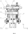
FIG. 2 is a schematic cross-sectional view of the vehicle power system ofFIG. 1 . -
FIG. 3 is a structural schematic view of an end surface showing a meshing relationship of the vehicle power system inFIG. 2 . -
FIG. 4 is a schematic structural diagram of the vehicle power system according to another embodiment of the present disclosure. -
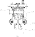
FIG. 5 is a schematic cross-sectional view of the vehicle power system ofFIG. 4 . -
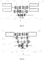
FIG. 6 is a schematic structural diagram of the vehicle power system according to still another embodiment of the present disclosure. -
FIG. 7 is a schematic structural diagram of the vehicle power system according to still another embodiment of the present disclosure. -
FIG. 8 is a schematic structural diagram of the vehicle power system according to still another embodiment of the present disclosure. -
FIG. 9 is a schematic structural diagram of the vehicle power system according to still another embodiment of the present disclosure. - The realization of the purposes, functional features and advantages of the present application will be further explained with reference to the accompanying drawings in combination with the embodiments.
- In the following, the embodiments of the present application will be clearly and completely described with reference to the drawings in the embodiments of the present application. Obviously, the described embodiments are only some of the embodiments of the present application, and not all of the embodiments. Based on the embodiments of the present application, all other embodiments obtained by those of ordinary skilled in the art without creative efforts shall fall within the claimed scope of the present application.
- It should be noted that all directional indicators (such as up, down, left, right, front, back, etc.) in the embodiments of the present application are only used to explain the relative positional relationship, movement situation, etc. between components in a specific attitude (as shown in the drawings). If the specific attitude changes, the directional indication also changes accordingly.
- In addition, the descriptions related to "first", "second" and the like in the present application are for descriptive purposes only, and should not be understood as indicating or implying their relative importance or implicitly indicating the number of technical features indicated. Therefore, a feature defined by "first" and "second" may explicitly or implicitly include at least one of such feature. In addition, the meaning of "and/or" in the full text includes three parallel solutions, taking "A and/or B" as an example, it includes solution A, solution B, or both solutions A and B. The various embodiments can be combined with each other, but the combination must be based on what can be achieved by those of ordinary skill in the art. When the combination of the embodiments is contradictory or cannot be achieved, it should be considered that such a combination does not exist, or is not within the scope of the claims of the present application.
- At present, with the development of new energy vehicle industries, electric vehicles have become a trend. The performance of the electric vehicle attracts more and more attention. Limited by the motor, the volume and weight of the current motor are increased significantly when the current single motor has high power, which limits the development of high performance electric vehicles. Furthermore, as the consumers pay more attention to the performance, the demand for power configurations such as vector control, differential lock and the like is increasing daily. In order to ensure that the transmission system can achieve functions such as differential speed, differential lock and vector control, additional mechanical mechanisms (e.g., a speed reduction mechanism, a differential mechanism, and a vector adjustment mechanism, etc.) need to be provided in the transmission system, which increases the volume and weight of the transmission system, and results in more energy consumption of the vehicle.
- In view of this, the present application provides a vehicle power system, and
FIG. 1 to FIG. 9 are some embodiments of the vehicle power system provided by the present application. In the following the vehicle power system is described with reference to specific drawings. - Referring to
FIG. 1 to FIG. 3 , the vehicle power system 100 includes a vehicle power transmission system and a driving motor 1. The driving motor 1 is connected to amotor output shaft 10 of the power transmission system, or themotor output shaft 10 of the power transmission system is also an output shaft of the driving motor. The vehicle power transmission system includes twomotor output shafts 10, twopower output shafts 30, and two transmission mechanisms respectively connected between the twomotor output shafts 10 and the twopower output shafts 30 correspondingly. Each transmission mechanism includes amotor output gear 14, apower output gear 31 and an middle transmission gear structure. Themotor output gear 14 is arranged on themotor output shaft 10 and thepower output gear 31 is arranged on thepower output shaft 30. The middle transmission gear structure is in transmission connection with both themotor output gear 14 and thepower output gear 31. The twopower output shafts 30 are extended along a first direction. The first direction is a direction of the X axis in this embodiment. Projections of the twomotor output shafts 10 along the X axis are at least partially overlapped; and/or projections of the two transmission mechanisms along the X axis are at least partially overlapped. - In this embodiment of the present application, the vehicle power transmission system includes two
motor output shafts 10, twopower output shafts 30, and two transmission mechanisms respectively connected between the twomotor output shafts 10 and the twopower output shafts 30 correspondingly. In this way, the two driving motors 1 provide power individually and do not affect each other. When a differential function or vector control needs to be carried out, only the output speeds of the two driving motors 1 need to be adjusted. At the same time, the twopower output shafts 30 are extended along the X axis, and the projections of the twomotor output shafts 10 along the X axis are at least partially overlapped and arranged. and the projections of the two transmission mechanisms along the X axis are at least partially overlapped. By this way, the volume of the vehicle power system 100 can be further reduced. The volume of the vehicle power system 100 is smaller, and the structure is more compact. - It should be noted that, in the present application, the driving forces of the two driving motors 1 are output through the two
motor output shafts 10. The two motor output gears 14 rotate with the twomotor output shafts 10 synchronously. The the two motor output gears 14 are engaged with the two middle input gears 21 correspondingly, and the two middle output gears 22 synchronize respectively with the two middle input gears 21 through twomiddle shafts 20, The two middle output gears 22 are engaged with the two power output gears 31 correspondingly, and the twopower output shafts 30 synchronize respectively with the power output gears 31. The twopower output shafts 31 respectively drive external loads connected to a vehicle. The external loads of the vehicle is a left wheel and a right wheel of the vehicle. - In this embodiment, one of the driving motors 1 transmits power to one of the transmission mechanisms, one of the transmission mechanisms transmits the power to one of the
power output shafts 30, and one of thepower output shafts 30 transmits the power to the left wheel of the vehicle. The other one of the driving motors 1 transmits power to the other one of the transmission mechanisms, the other one of the transmission mechanisms transmit the power to the other one of thepower output shafts 30, and the other one of thepower output shafts 30 transmits the power to the right wheel of the vehicle. During the transmission process, the power transmission processes on both sides are independent from each other. Therefore, through the above structure, the differential speed control, the differential lock function and the vector control can be realized. Therefore, the vehicle power system 100 does not need additional deceleration mechanisms, addition differential speed mechanisms and addition vector control mechanisms to realize the differential speed control, the differential lock function and the vector control. Therefore the overall volume and weight of the vehicle power system 100 are reduced, the structure is more compact, and the overall power density is improved. - When the vehicle is in a stable driving process, the rotating speeds of the two driving motors 1 are the same. The rotating speeds transmitted to the left wheel and the right wheel of the vehicle are the same, and the vehicle moves straight ahead stably. When the vehicle needs a turning, in order to prevent the wheels from slipping, the rotating speeds of the left wheel and the right wheel need to be controlled to be different. At this time, only the rotating speed of a corresponding driving motor 1 needs to be controlled according to a direction of turning of the vehicle. Thus the differential speed function and the vector control function can be realized.
- For ease of description, in the present application, the two driving motors 1 are referred as a
first driving motor 11 and asecond driving motor 12, the twomiddle shafts 20 are referred as a firstmiddle shaft 201 and a secondmiddle shaft 202, the twomotor output shafts 10 are referred as a first motor output shaft and a second motor output shaft, the two motor output gears 14 are referred as a firstmotor output gear 141 and a secondmotor output gear 142, the two middle input gears 21 are referred as a firstmiddle input gear 211 and a secondmiddle input gear 212, the two middle output gears 22 are referred as a firstmiddle output gear 221 and a secondmiddle output gear 222, the twopower output shafts 30 are referred as a firstpower output shaft 301 and a secondpower output shaft 302, and the two power output gears 31 are referred as a firstpower output gear 311 and a second power output gear 312. Those defined with the "first" belong to one power transmission chain and those defined with the "second" belong to another power transmission chain. - Referring to
FIG. 1 to FIG. 5 , in order to reduce the volume of the two transmission mechanisms, the twomotor output shafts 10 have a same axis and are opposite to each other in the X axis, and the middle transmission gear structures are at least partially overlapped. Specifically, each middle transmission gear structures includes amiddle shaft 20, a middle input gear 21 and a middle output gear 22. The middle input gear 21 and the middle output gear 22 rotate synchronously through themiddle shaft 20. Both themiddle shafts 20 are arranged in parallel with themotor output shafts 10. Along a direction from themotor output shafts 10 to thepower output shafts 30, namely along a second direction which is a direction of the Z axis in this embodiment, the Z axis is perpendicular to the X axis. The X axis, the Y axis and the Z axis form a coordinate system. As shown inFIG. 2 , at least portions of the projections of themiddle shafts 20 are overlapped along an extending direction of themiddle shafts 20. As shown inFIG. 3 , portions of the projections of the middle input gears 21 are overlapped. In one embodiment, as shown inFIG. 2 , a first portion of each middle shaft is integrally formed with the corresponding middle input gear 21, a second portion of each middle shaft is integrally formed with the corresponding middle output gear 22, and the first portion of the middle shaft is connected to the second portion of the middle shaft through a spline. Of course, the middle input gear, the middle shaft and the middle shaft output gear may be integrally formed. Along the X axis, the vehicle power system 100 is divided into two equal part: a first part and a second part. The middle input gear and the middle output gear of one of the transmission mechanisms are located on a same side such as located in the first part long the X axis, and the middle input gear and the middle output gear of the other of the transmission mechanisms are located on the other same side such as located in the second part along the X axis. Further, as shown inFIG. 1 andFIG. 2 , along the X axis, thefirst input gear 211 and thefirst output gear 221 of the first transmission mechanism are located in the first part on the left side, and thesecond input gear 212 and thesecond output gear 222 of the second transmission mechanism are located in the second part on the right side. In this way, the first transmission mechanism and the second transmission mechanism are symmetrically arranged,which is beneficial not only to the stability of the system, but also to the reduction of the volume of the vehicle power system 100 to some extent. - Referring to
FIG. 4 andFIG. 5 , the twomotor output shafts 14 are arranged opposite to each other along the X axis. The middle transmission gear structures are at least partially overlapped. The middle transmission gear structure includes amiddle shaft 20, a middle input gear 21 and a middle output gear 22. The middle input gear 21 and the middle output gear 22 rotate synchronously through themiddle shaft 20. Both themiddle shafts 20 are arranged in parallel with themotor output shafts 14. As shown inFIG. 5 , along a direction from themotor output shafts 10 to thepower output shafts 30, at least portions of the projections of themiddle shafts 20 are overlapped. As shown inFIG. 3 , along the extending direction of themiddle shafts 20, portions of the projections of the two middle input gears are overlapped. Each middle shaft is of a split structure, a first portion of the middle shaft is integrally formed with the middle input gear, and a second portion of the middle shaft is integrally formed with the middle output gear. The first portion of the middle shaft is connected to the second portion of the middle shaft through a spline. Of course, the middle input gear, the middle shaft and the middle output gear can be integrally formed, which is not limited herein and can be designed according to an actual requirement for arrangement of parts. The vehicle power system 100 is divided into two equal parts along the X axis. The middle input gear of one of the transmission mechanisms and the middle output gear of the other of the transmission mechanisms are located on the same side along the X axis, such as the left part or the right part shown in the figures. As shown inFIG. 4 andFIG. 5 , the firstmiddle input gear 211 of the first transmission mechanism and the secondmiddle output gear 222 of the second transmission mechanism are located on the left part along the X axis, and the first middle output gear of the first transmission mechanism and the second middle input gear of the second transmission mechanism are located on the right part along the X axis. - Referring to
FIG. 7 andFIG. 8 , the twomotor output shafts 10 are arranged opposite to each other along the X axis, and the middle transmission gear structures are at least partially overlapped. In an embodiment, the two middle shafts are coaxially nested, and an extending direction of the twopower output shafts 30 are defined as a direction of the X axis. The extending direction of themotor output shafts 10 is the same as the direction of the X axis, and the twomotor output shafts 10 are arranged coaxially and opposite to each other. From themotor output shafts 10 to thepower output shafts 30, the firstmiddle shaft 201 is provided with a through hole, and the secondmiddle shaft 202 passes through the through hole. The two middle input gears are referred as the firstmiddle input gear 211 and the secondmiddle input gear 212. The two middle output gears are defined as the firstmiddle output gear 221 and the secondmiddle output gear 222. The firstmiddle input gear 211 and the firstmiddle output gear 221 are in synchronous transmission connection with each other through the firstmiddle shaft 201, and thesecond input gear 212 and thesecond output gear 222 are in transmission connection with each other through the secondmiddle shaft 202. In the present embodiment, the secondmiddle shaft 202 has an end received in the first middle shaft 201.That is, the firstmiddle shaft 201 and the secondmiddle shaft 202 are coaxially nested, and thus an axial length of the transmission mechanism is reduced. The volume of the vehicle power system 100 is reduced and the structure is more compact. - As shown in
FIG. 7 , the firstmiddle input gear 211 and the firstmiddle output gear 221 are located between the secondmiddle input gear 212 and the secondmiddle output gear 222. It should be noted that, in the present embodiment, since a relative rotating speed between the firstmiddle shaft 201 and the secondmiddle shaft 202 is smaller, the requirement on performance of the bearing are correspondingly lower, and thus needle bearings or thrust bearings can be used, which can reduce the weight of the vehicle power system 100 to a certain extent. In an embodiment, aneedle bearing 61 is provided between the firstmiddle shaft 201 and the secondmiddle shaft 201, and a first thrust bearing 63 is provided between the firstmiddle input gear 211 and the secondmiddle shaft 202. In another embodiment, aneedle bearing 61 is provided between the firstmiddle shaft 201 and the secondmiddle shaft 201, and a first thrust bearing 63 is provided between the secondmiddle output gear 222 and the secondmiddle shaft 202. In yet another embodiment, a second thrust bearing 64 is provided between the firstmiddle output gear 221 and the secondmiddle shaft 202. In still another embodiment, a second thrust bearing 64 is provided between the secondmiddle input gear 212 and the secondmiddle shaft 202. - Referring to
FIG. 8 , the vehicle power system 100 is divided into two equal parts along the X axis. The firstmiddle input gear 211 and the firstmiddle output gear 221 are located on the same side of the secondmiddle shaft 202 along the X axis, namely on the left part of the secondmiddle shaft 201 shown in the figure. The secondmiddle output gear 222 and the secondmiddle input gear 212 are located on the other side of the secondmiddle shaft 202 along the X axis, namely on the right part of the secondmiddle shaft 201. Aneedle bearing 61 is provided between the firstmiddle shaft 201 and the secondmiddle shaft 201. A first thrust bearing 63 is provided between the firstmiddle input gear 211 and the secondmiddle shaft 202, and a second thrust bearing 64 is provided between the firstmiddle output gear 221 and the secondmiddle shaft 202. - With reference to
FIG. 6 , the twomotor output shafts 10 are perpendicular to the Z axis, and the X axis is perpendicular to the Z axis. Along the Z axis, the two transmission mechanisms are located between the twomotor output shafts 10. Along the Z axis, the twomiddle shafts 20 are located between the twopower output shafts 30. Along the X axis, the twomotor output shafts 10 are located between the twopower output shafts 30. Axes of the twopower output shafts 30 are coaxially arranged along the X axis. Axes of the twopower output shafts 30 are coaxially arranged and the two power output gears 30 are oppositely to each other. - As shown in
FIG. 1 ,FIG. 2 ,FIG. 4 andFIG. 5 , at least one of the transmission mechanisms includes at least one set of nesting structure, and the nesting structure includes a supportingportion 53, anesting bearing 52, and a transmission gear. The transmission gear is at least one of the motor output gears 14, the power output gears 31, the middle output gears 22 and the middle input gears 21. The transmission gear is provided with a second mountingcavity 51. At least a portion of the transmission gear is received in the second mountingcavity 51. The transmission gear is supported on the supportingportion 53 through thenesting bearing 52. The supportingportion 53 is a protruding portion of the housing or the supporting portion is fixedly connected to the housing. - With reference to
FIG. 9 , at least one group of the two motor output shafts, the two power output shafts, and the two middle shafts are arranged coaxially and opposite to each other. At least a gear at an end of one of the coaxial shafts is provided with a first mountingcavity 41. The transmission system includes afirst bearing 42, and at least a portion of thefirst bearing 42 is located in the first mountingcavity 41. An end of the other of the coaxial shafts is supported by the first bearing.The above is only an optional embodiment of the present application, and is not therefore limiting the scope of the present application. Any equivalent structural transformation made based on the contents of the specification and drawings of the present application or any direct/indirect application in other related technical fields under the inventive concept of the present application is included in the claimed scope of the present application.
| Reference numeral | Name | Reference numeral | Name |
| 100 | Vehicle power system | 21 | Middle input gear |
| 1 | | 211 | First |
| 11 | | 212 | Second |
| 12 | Second driving motor | 22 | |
| 10 | | 221 | First |
| 20 | | 222 | Second |
| 30 | | 31 | |
| 14 | | 201 | First |
| 41 | First mounting | 202 | Second |
| 42 | First bearing | 61 | Needle bearing |
| 43 | Thrust bearing | 311 | First |
| 51 | Second mounting cavity | 312 | Second |
| 52 | | 301 | First |
| 53 | | 302 | Second |
| 141 | First | 142 | Second |
| 63 | First thrust bearing | 64 | Second thrust bearing |
Claims (11)
- A vehicle power transmission system, characterized by comprising two motor output shafts, two power output shafts, and two transmission mechanisms respectively connected between the two motor output shafts and the two power output shafts correspondingly, wherein each transmission mechanism comprises a motor output gear, a power output gear and a middle transmission gear structure, the motor output gear is arranged on the motor output shaft, and the power output gear is arranged on the power output shaft, the middle transmission gear structure is in transmission connection with the motor output gear and the power output gear, and the two power output shafts are extended in a first direction,wherein along the first direction, projections of the two motor output shafts are at least partially overlapped; and/orprojections of the two transmission mechanisms are at least partially overlapped.
- The vehicle power transmission system according to claim 1, wherein:the two motor output shafts are arranged coaxially and opposite to each other in the first direction;the two middle transmission gear structures are at least partially overlapped, each middle transmission gear structure comprising a middle shaft, a middle input gear and a middle output gear, the middle input gear being synchronous with the middle output gear through the middle shaft;two middle shafts are arranged in parallel with the two motor output shafts;projections of the two middle shafts are at least partially overlapped along a direction from the two motor output shaft to the two power output shafts;projections of two middle input gears are partially overlapped along an extending direction of the middle shaft; andthe middle input gear and the middle output gear of one of the transmission mechanisms are located on a same side along the first direction, and the middle input gear and the middle output gear of the other of the transmission mechanisms are located on another same side along the first direction.
- The vehicle power transmission system according to claim 1, wherein:the two motor output shafts are arranged coaxially and opposite to each other in the first direction;the two middle transmission gear structures are at least partially overlapped, each of the middle transmission gear structures comprising a middle shaft, a middle input gear and a middle output gear, the middle input gear and the middle output gear being rotated synchronously through the middle shaft;two middle shafts are arranged in parallel with the two motor output shafts;projections of the two middle shafts are at least partially overlapped along a direction from the two motor output shaft to the two power output shafts;projections of two middle input gears are partially overlapped along an extending direction of the middle shaft; andthe middle input gear of one of the transmission mechanisms and the middle output gear of the other of the transmission mechanisms are located on a same side along the first direction.
- The vehicle power transmission system according to claim 2 or 3, wherein the middle shaft is of a split structure, a first portion of the middle shaft is integrally formed with the middle input gear, a second portion of the middle shaft is integrally formed with the middle output gear, and the first portion of the middle shaft is connected to the second portion of the middle shaft through a spline.
- The vehicle power transmission system according to claim 1, wherein:the two motor output shafts are arranged coaxially and opposite to each other along the first direction;the two middle transmission gear structures are at least partially overlapped, each of the middle transmission gear structures comprising a middle shaft, a middle input gear and a middle output gear, the middle input gear and the middle output gear being rotated synchronously through the middle shaft;two middle shafts are coaxially nested and comprise a first middle shaft and a second middle shaft, the first middle shaft is provided with a through hole, and an end of the second middle shaft is received in the through hole, two middle input gears comprise a first middle input gear and a second middle input gear, and two middle output gears comprise a first middle output gear and a second middle output gear, the first middle input gear and the first middle output gear are synchronously transmission connected through the first middle shaft, and the second middle input gear and the second middle output gear are synchronously transmission connected through the second middle shaft.
- The vehicle power transmission system according to claim 5, wherein:the first middle input gear and the first middle output gear are located between the second middle input gear and the second middle output gear;a needle bearing is provided between the first middle shaft and the second middle shaft;a first thrust bearing is provided between the first middle input gear and the second middle shaft or the second middle output gear; anda second thrust bearing is provided between the first middle output gear and the second middle shaft or the second middle input gear.
- The vehicle power transmission system according to claim 5, wherein the first middle input gear and the first middle output gear are located on a same side of the second middle shaft along the first direction, the second middle output gear and the second middle input gear are located on another side of the second middle shaft along the first direction, a first thrust bearing is provided between the first middle input gear and the second middle shaft, a second thrust bearing is provided between the first middle output gear and the second middle shaft, or between the second middle output gear and the second middle shaft.
- The vehicle power transmission system according to claim 1, wherein the two motor output shafts are perpendicular to a second direction, the first direction is perpendicular to the second direction. The two transmission mechanisms are located between the two motor output shafts along the second direction, two middle shafts are located between the motor output shafts along the second direction, the two motor output shafts are located between the power output shafts along the first direction, axes of the two middle shafts are coaxial along the first direction, axes of the two power output shafts are coaxial, and the two power output gears are opposite to each other.
- The vehicle power transmission system according to any one of claims 2 to 8, wherein the vehicle power transmission system further comprises a housing;
at least one of the transmission gears comprises at least one set of nesting structure, the nesting structure comprises a supporting portion, a nesting bearing and a transmission gear, the transmission gear is at least one of the motor output gears, the power output gears, the middle output gears and the middle input gears, the transmission gear is provided with a mounting cavity, at least a portion of the nesting bearing is located in the mounting cavity, the transmission gear is supported on the supporting portion through the nesting bearing, and the supporting portion is a protruding portion of the housing or the supporting portion is fixedly connected to the housing. - The vehicle power transmission system according to any one of claims 2 to 8, wherein at least one group of the two motor output shafts, the two power output shafts, and the two middle shafts are arranged coaxially and opposite to each other, At least a gear at an end of one of coaxial shafts is provided with a first mounting cavity, the transmission system comprises a first bearing, at least a portion of the first bearing is located in the first mounting cavity, and an end of another of the coaxial shafts is supported by the first bearing.
- A vehicle power system, comprising:the vehicle power transmission system according to any one of claims 1 to 10; anddriving motors, wherein the driving motors are connected to the motor output shafts or the motor output shafts are output shafts of the driving motors.
Applications Claiming Priority (2)
| Application Number | Priority Date | Filing Date | Title |
|---|---|---|---|
| CN202210159507.6A CN114290885A (en) | 2022-02-21 | 2022-02-21 | Vehicle power transmission system and vehicle power system |
| PCT/CN2022/093642 WO2022207011A1 (en) | 2022-02-21 | 2022-05-18 | Vehicle power transmission system, and vehicle power system |
Publications (2)
| Publication Number | Publication Date |
|---|---|
| EP4091851A1 true EP4091851A1 (en) | 2022-11-23 |
| EP4091851A4 EP4091851A4 (en) | 2024-04-24 |
Family
ID=80978096
Family Applications (1)
| Application Number | Title | Priority Date | Filing Date |
|---|---|---|---|
| EP22738525.9A Pending EP4091851A4 (en) | 2022-02-21 | 2022-05-18 | VEHICLE POWER TRANSMISSION SYSTEM AND VEHICLE POWER SYSTEM |
Country Status (6)
| Country | Link |
|---|---|
| US (1) | US12194840B2 (en) |
| EP (1) | EP4091851A4 (en) |
| JP (1) | JP7573629B2 (en) |
| KR (1) | KR102719311B1 (en) |
| CN (2) | CN114290885A (en) |
| WO (1) | WO2022207011A1 (en) |
Cited By (2)
| Publication number | Priority date | Publication date | Assignee | Title |
|---|---|---|---|---|
| US20240247703A1 (en) * | 2023-01-23 | 2024-07-25 | Beyerische Motoren Werke Aktiengesellschaft | Transmission for a Coaxial Two-Machine Electric Drive of a Motor Vehicle |
| DE102023116814A1 (en) * | 2023-06-27 | 2025-01-02 | Bayerische Motoren Werke Aktiengesellschaft | transmission for a motor vehicle |
Families Citing this family (7)
| Publication number | Priority date | Publication date | Assignee | Title |
|---|---|---|---|---|
| CN114290885A (en) | 2022-02-21 | 2022-04-08 | 浙江吉利控股集团有限公司 | Vehicle power transmission system and vehicle power system |
| CN116872723A (en) * | 2023-08-11 | 2023-10-13 | 芜湖埃科泰克动力总成有限公司 | Transmission coupling devices, power systems and automobiles |
| CN117103969A (en) * | 2023-08-14 | 2023-11-24 | 无锡星驱动力科技有限公司 | A dual-motor electric drive system, powertrain and vehicle |
| CN117284069A (en) * | 2023-10-08 | 2023-12-26 | 东风汽车集团股份有限公司 | Vehicle distributed drive system and drive assembly |
| CN117284067A (en) * | 2023-10-08 | 2023-12-26 | 东风汽车集团股份有限公司 | Vehicle distributed drive system and drive assembly |
| CN117301835A (en) * | 2023-10-08 | 2023-12-29 | 东风汽车集团股份有限公司 | Vehicle distributed drive system and drive assembly |
| GB2639185A (en) * | 2024-03-05 | 2025-09-17 | Jaguar Land Rover Ltd | Vehicle drive system |
Family Cites Families (30)
| Publication number | Priority date | Publication date | Assignee | Title |
|---|---|---|---|---|
| US7954574B2 (en) | 2007-03-23 | 2011-06-07 | Fairfield Manufacturing Company, Inc. | Offset drive system for utility vehicles |
| KR20100023345A (en) * | 2008-08-21 | 2010-03-04 | 현대자동차주식회사 | Compound planetery gear set of automatic transmission for vehicles |
| DE102009006523B4 (en) * | 2009-01-28 | 2011-04-28 | Getrag Getriebe- Und Zahnradfabrik Hermann Hagenmeyer Gmbh & Cie Kg | Electric axle arrangement |
| CN202001581U (en) * | 2011-01-23 | 2011-10-05 | 徐工集团工程机械股份有限公司科技分公司 | Integral type shaft gear |
| JP2013108604A (en) * | 2011-11-24 | 2013-06-06 | Aisin Seiki Co Ltd | Vehicle driving device |
| DE102011056047B4 (en) * | 2011-12-05 | 2024-07-04 | Dr. Ing. H.C. F. Porsche Aktiengesellschaft | Drivetrain of a purely electric all-wheel drive vehicle |
| BE1024269B1 (en) | 2016-06-08 | 2018-01-15 | Punch Powertrain Nv | ELECTRIC DRIVE, TRANSMISSION, AND VEHICLE |
| FR3053007B1 (en) * | 2016-06-28 | 2019-08-23 | France Reducteurs | TRANSMISSION, IN PARTICULAR FOR ROLLER, AND ROLLER EQUIPPED WITH SUCH TRANSMISSION |
| CN206681975U (en) * | 2017-04-07 | 2017-11-28 | 湖北大旗液压有限公司 | A kind of Integral output shaft for being exclusively used in hydraulic gear pump |
| US11192448B2 (en) * | 2017-08-16 | 2021-12-07 | Allison Transmission, Inc. | Axle assembly for frame rail vehicles |
| EP3667876B1 (en) * | 2017-11-17 | 2022-11-23 | Aisin Corporation | Vehicle drive device |
| CN110091700B (en) * | 2018-01-31 | 2020-11-06 | 华为技术有限公司 | Speed reducer, driving device and electric automobile |
| JP2019158119A (en) * | 2018-03-16 | 2019-09-19 | 本田技研工業株式会社 | Shaft arrangement structure of electrically-driven unit |
| CN208232814U (en) * | 2018-04-04 | 2018-12-14 | 精进电动科技股份有限公司 | A kind of vehicle dual power source double drive assembly |
| CN208153526U (en) * | 2018-05-10 | 2018-11-27 | 台州市北光机械制造有限公司 | A kind of combined type splined shaft of connection gear box body |
| CN109318697A (en) * | 2018-10-26 | 2019-02-12 | 蔚来汽车有限公司 | power system, vehicle, control system and control method of vehicle |
| EP3663118A1 (en) * | 2018-12-04 | 2020-06-10 | AVL MTC Motortestcenter AB | Transmission arrangement for a drive system of a vehicle |
| IT201800021025A1 (en) * | 2018-12-24 | 2020-06-24 | Fpt Ind Spa | MODULAR ELECTRIC TRACTION SYSTEM |
| JP2020143715A (en) * | 2019-03-05 | 2020-09-10 | アイシン・エィ・ダブリュ株式会社 | Drive transmission device for vehicle |
| CN114080520A (en) * | 2019-07-09 | 2022-02-22 | 浩夫尔动力总成有限公司 | Transmission, in particular manual transmission, and bearing carrier for advantageous oil lubrication by means of a multi-chamber system, and method suitable for lubricating a transmission |
| JP7521371B2 (en) | 2019-10-10 | 2024-07-24 | 日本精工株式会社 | Drive device for electric vehicle, drive unit and electric vehicle |
| CN212455431U (en) * | 2020-05-26 | 2021-02-02 | 蜂巢传动科技河北有限公司 | Speed reduction mechanism, transmission case, and drive device |
| US11440513B2 (en) * | 2020-06-04 | 2022-09-13 | Bendix Commercial Vehicle Systems, Llc | Parking brake for an electric vehicle with multi-speed gearbox |
| US11628713B2 (en) * | 2020-06-04 | 2023-04-18 | Rivian Ip Holdings, Llc | Electric vehicle powertrain assembly having nested shafts |
| CN215284326U (en) * | 2021-05-20 | 2021-12-24 | 长城汽车股份有限公司 | Torque transmission system and vehicle |
| CN113513572B (en) * | 2021-05-31 | 2024-07-02 | 蜂巢传动科技河北有限公司 | Speed reducer for vehicle and vehicle with same |
| DE102021206732A1 (en) | 2021-06-29 | 2022-12-29 | Zf Friedrichshafen Ag | Drive arrangement for a vehicle |
| CN215435960U (en) * | 2021-06-30 | 2022-01-07 | 比亚迪股份有限公司 | Electric drive assembly, four-wheel drive system and car |
| CN113910882A (en) | 2021-10-18 | 2022-01-11 | 上海蔚兰动力科技有限公司 | Electric drive axle assembly for automobile and automobile |
| CN114290885A (en) * | 2022-02-21 | 2022-04-08 | 浙江吉利控股集团有限公司 | Vehicle power transmission system and vehicle power system |
-
2022
- 2022-02-21 CN CN202210159507.6A patent/CN114290885A/en active Pending
- 2022-05-18 KR KR1020227029018A patent/KR102719311B1/en active Active
- 2022-05-18 JP JP2022547858A patent/JP7573629B2/en active Active
- 2022-05-18 WO PCT/CN2022/093642 patent/WO2022207011A1/en not_active Ceased
- 2022-05-18 EP EP22738525.9A patent/EP4091851A4/en active Pending
- 2022-07-28 US US17/876,233 patent/US12194840B2/en active Active
- 2022-10-11 CN CN202211244426.2A patent/CN115593205A/en active Pending
Cited By (3)
| Publication number | Priority date | Publication date | Assignee | Title |
|---|---|---|---|---|
| US20240247703A1 (en) * | 2023-01-23 | 2024-07-25 | Beyerische Motoren Werke Aktiengesellschaft | Transmission for a Coaxial Two-Machine Electric Drive of a Motor Vehicle |
| US12595840B2 (en) * | 2023-01-23 | 2026-04-07 | Bayerische Motoren Werke Aktiengesellschaft | Transmission for a coaxial two-machine electric drive of a motor vehicle |
| DE102023116814A1 (en) * | 2023-06-27 | 2025-01-02 | Bayerische Motoren Werke Aktiengesellschaft | transmission for a motor vehicle |
Also Published As
| Publication number | Publication date |
|---|---|
| US20230264566A1 (en) | 2023-08-24 |
| WO2022207011A1 (en) | 2022-10-06 |
| CN114290885A (en) | 2022-04-08 |
| KR20230126180A (en) | 2023-08-29 |
| JP7573629B2 (en) | 2024-10-25 |
| CN115593205A (en) | 2023-01-13 |
| US12194840B2 (en) | 2025-01-14 |
| KR102719311B1 (en) | 2024-10-18 |
| EP4091851A4 (en) | 2024-04-24 |
| JP2023522814A (en) | 2023-06-01 |
Similar Documents
| Publication | Publication Date | Title |
|---|---|---|
| US12194840B2 (en) | Vehicle power transmission system and vehicle power system | |
| US11642951B2 (en) | Multi-mode torque vectoring electric drive axle with single actuator | |
| EP4230453A1 (en) | Multi-motor flexible torque centralized driving synthesis box and electric vehicle | |
| EP4227148A1 (en) | Battery-replacement-type carrying vehicle without intermediate transmission shaft | |
| CN114435101B (en) | A vehicle power system | |
| US11988270B2 (en) | Electric drive assembly for electric vehicle, and electric vehicle | |
| CN218287331U (en) | Double-motor single-gear electric drive axle | |
| CN212604505U (en) | Coaxial two-gear planetary row electric drive axle for automobile | |
| JPS61143227A (en) | Vehicle driving device | |
| CN218670600U (en) | Gear shifting structure of power disconnecting mechanism | |
| WO2024001918A1 (en) | Hybrid drive system, gearbox and vehicle | |
| CN115157925A (en) | Electric drive axle assembly and vehicle | |
| CN114211946A (en) | Multi-mode electric drive axle of double-rotor motor coupling conical differential mechanism unilateral axle housing | |
| CN115056641A (en) | a vehicle power system | |
| CN119911086B (en) | A gearless parallel shaft multi-mode dual-motor coupled drive system | |
| CN223434689U (en) | Novel transfer case power take-off device | |
| CN222473898U (en) | Novel double-planetary-row mixing system suitable for light truck | |
| CN223803410U (en) | The vehicle's drivetrain and vehicle | |
| CN223702301U (en) | Driving axle structure and vehicle with same | |
| CN220727039U (en) | Disconnecting differential, drive axle and vehicle | |
| US12313036B2 (en) | Electric power generating device | |
| CN217784133U (en) | Pure electric system and vehicle | |
| CN223187338U (en) | Four-wheel drive transmission system and vehicle | |
| CN218598741U (en) | Dual-motor six-gear electric drive transmission system and vehicle | |
| CN222185641U (en) | Unpowered interrupt transmission assembly |
Legal Events
| Date | Code | Title | Description |
|---|---|---|---|
| STAA | Information on the status of an ep patent application or granted ep patent |
Free format text: STATUS: UNKNOWN |
|
| STAA | Information on the status of an ep patent application or granted ep patent |
Free format text: STATUS: THE INTERNATIONAL PUBLICATION HAS BEEN MADE |
|
| PUAI | Public reference made under article 153(3) epc to a published international application that has entered the european phase |
Free format text: ORIGINAL CODE: 0009012 |
|
| STAA | Information on the status of an ep patent application or granted ep patent |
Free format text: STATUS: REQUEST FOR EXAMINATION WAS MADE |
|
| 17P | Request for examination filed |
Effective date: 20220722 |
|
| AK | Designated contracting states |
Kind code of ref document: A1 Designated state(s): AL AT BE BG CH CY CZ DE DK EE ES FI FR GB GR HR HU IE IS IT LI LT LU LV MC MK MT NL NO PL PT RO RS SE SI SK SM TR |
|
| A4 | Supplementary search report drawn up and despatched |
Effective date: 20240327 |
|
| RIC1 | Information provided on ipc code assigned before grant |
Ipc: B60K 17/04 20060101ALI20240321BHEP Ipc: B60K 1/02 20060101AFI20240321BHEP |
|
| RAP1 | Party data changed (applicant data changed or rights of an application transferred) |
Owner name: WUXI INFIMOTION TECHNOLOGY CO., LTD. Owner name: WUXI INFIMOTION PROPULSION TECHNOLOGY CO., LTD. |
|
| DAV | Request for validation of the european patent (deleted) | ||
| DAX | Request for extension of the european patent (deleted) |