EP4091706B1 - Venturi nozzle apparatus - Google Patents
Venturi nozzle apparatus Download PDFInfo
- Publication number
- EP4091706B1 EP4091706B1 EP21203446.6A EP21203446A EP4091706B1 EP 4091706 B1 EP4091706 B1 EP 4091706B1 EP 21203446 A EP21203446 A EP 21203446A EP 4091706 B1 EP4091706 B1 EP 4091706B1
- Authority
- EP
- European Patent Office
- Prior art keywords
- end portion
- water
- gas
- flow
- venturi
- Prior art date
- Legal status (The legal status is an assumption and is not a legal conclusion. Google has not performed a legal analysis and makes no representation as to the accuracy of the status listed.)
- Active
Links
Images



Classifications
-
- B—PERFORMING OPERATIONS; TRANSPORTING
- B05—SPRAYING OR ATOMISING IN GENERAL; APPLYING FLUENT MATERIALS TO SURFACES, IN GENERAL
- B05B—SPRAYING APPARATUS; ATOMISING APPARATUS; NOZZLES
- B05B7/00—Spraying apparatus for discharge of liquids or other fluent materials from two or more sources, e.g. of liquid and air, of powder and gas
- B05B7/02—Spray pistols; Apparatus for discharge
- B05B7/04—Spray pistols; Apparatus for discharge with arrangements for mixing liquids or other fluent materials before discharge
- B05B7/0416—Spray pistols; Apparatus for discharge with arrangements for mixing liquids or other fluent materials before discharge with arrangements for mixing one gas and one liquid
-
- B—PERFORMING OPERATIONS; TRANSPORTING
- B01—PHYSICAL OR CHEMICAL PROCESSES OR APPARATUS IN GENERAL
- B01F—MIXING, e.g. DISSOLVING, EMULSIFYING OR DISPERSING
- B01F23/00—Mixing according to the phases to be mixed, e.g. dispersing or emulsifying
- B01F23/20—Mixing gases with liquids
- B01F23/23—Mixing gases with liquids by introducing gases into liquid media, e.g. for producing aerated liquids
- B01F23/232—Mixing gases with liquids by introducing gases into liquid media, e.g. for producing aerated liquids using flow-mixing means for introducing the gases, e.g. baffles
- B01F23/2323—Mixing gases with liquids by introducing gases into liquid media, e.g. for producing aerated liquids using flow-mixing means for introducing the gases, e.g. baffles by circulating the flow in guiding constructions or conduits
-
- B—PERFORMING OPERATIONS; TRANSPORTING
- B01—PHYSICAL OR CHEMICAL PROCESSES OR APPARATUS IN GENERAL
- B01F—MIXING, e.g. DISSOLVING, EMULSIFYING OR DISPERSING
- B01F25/00—Flow mixers; Mixers for falling materials, e.g. solid particles
- B01F25/30—Injector mixers
- B01F25/31—Injector mixers in conduits or tubes through which the main component flows
- B01F25/312—Injector mixers in conduits or tubes through which the main component flows with Venturi elements; Details thereof
-
- B—PERFORMING OPERATIONS; TRANSPORTING
- B01—PHYSICAL OR CHEMICAL PROCESSES OR APPARATUS IN GENERAL
- B01F—MIXING, e.g. DISSOLVING, EMULSIFYING OR DISPERSING
- B01F23/00—Mixing according to the phases to be mixed, e.g. dispersing or emulsifying
- B01F23/20—Mixing gases with liquids
- B01F23/23—Mixing gases with liquids by introducing gases into liquid media, e.g. for producing aerated liquids
- B01F23/231—Mixing gases with liquids by introducing gases into liquid media, e.g. for producing aerated liquids by bubbling
- B01F23/23105—Arrangement or manipulation of the gas bubbling devices
-
- B—PERFORMING OPERATIONS; TRANSPORTING
- B01—PHYSICAL OR CHEMICAL PROCESSES OR APPARATUS IN GENERAL
- B01F—MIXING, e.g. DISSOLVING, EMULSIFYING OR DISPERSING
- B01F23/00—Mixing according to the phases to be mixed, e.g. dispersing or emulsifying
- B01F23/20—Mixing gases with liquids
- B01F23/23—Mixing gases with liquids by introducing gases into liquid media, e.g. for producing aerated liquids
- B01F23/232—Mixing gases with liquids by introducing gases into liquid media, e.g. for producing aerated liquids using flow-mixing means for introducing the gases, e.g. baffles
-
- B—PERFORMING OPERATIONS; TRANSPORTING
- B01—PHYSICAL OR CHEMICAL PROCESSES OR APPARATUS IN GENERAL
- B01F—MIXING, e.g. DISSOLVING, EMULSIFYING OR DISPERSING
- B01F23/00—Mixing according to the phases to be mixed, e.g. dispersing or emulsifying
- B01F23/20—Mixing gases with liquids
- B01F23/23—Mixing gases with liquids by introducing gases into liquid media, e.g. for producing aerated liquids
- B01F23/237—Mixing gases with liquids by introducing gases into liquid media, e.g. for producing aerated liquids characterised by the physical or chemical properties of gases or vapours introduced in the liquid media
- B01F23/2373—Mixing gases with liquids by introducing gases into liquid media, e.g. for producing aerated liquids characterised by the physical or chemical properties of gases or vapours introduced in the liquid media for obtaining fine bubbles, i.e. bubbles with a size below 100 µm
-
- B—PERFORMING OPERATIONS; TRANSPORTING
- B01—PHYSICAL OR CHEMICAL PROCESSES OR APPARATUS IN GENERAL
- B01F—MIXING, e.g. DISSOLVING, EMULSIFYING OR DISPERSING
- B01F25/00—Flow mixers; Mixers for falling materials, e.g. solid particles
- B01F25/30—Injector mixers
- B01F25/31—Injector mixers in conduits or tubes through which the main component flows
- B01F25/312—Injector mixers in conduits or tubes through which the main component flows with Venturi elements; Details thereof
- B01F25/3124—Injector mixers in conduits or tubes through which the main component flows with Venturi elements; Details thereof characterised by the place of introduction of the main flow
- B01F25/31242—Injector mixers in conduits or tubes through which the main component flows with Venturi elements; Details thereof characterised by the place of introduction of the main flow the main flow being injected in the central area of the venturi, creating an aspiration in the circumferential part of the conduit
-
- B—PERFORMING OPERATIONS; TRANSPORTING
- B01—PHYSICAL OR CHEMICAL PROCESSES OR APPARATUS IN GENERAL
- B01F—MIXING, e.g. DISSOLVING, EMULSIFYING OR DISPERSING
- B01F35/00—Accessories for mixers; Auxiliary operations or auxiliary devices; Parts or details of general application
- B01F35/56—General build-up of the mixers
-
- B—PERFORMING OPERATIONS; TRANSPORTING
- B01—PHYSICAL OR CHEMICAL PROCESSES OR APPARATUS IN GENERAL
- B01F—MIXING, e.g. DISSOLVING, EMULSIFYING OR DISPERSING
- B01F2101/00—Mixing characterised by the nature of the mixed materials or by the application field
- B01F2101/305—Treatment of water, waste water or sewage
-
- B—PERFORMING OPERATIONS; TRANSPORTING
- B01—PHYSICAL OR CHEMICAL PROCESSES OR APPARATUS IN GENERAL
- B01F—MIXING, e.g. DISSOLVING, EMULSIFYING OR DISPERSING
- B01F25/00—Flow mixers; Mixers for falling materials, e.g. solid particles
- B01F25/30—Injector mixers
- B01F25/31—Injector mixers in conduits or tubes through which the main component flows
- B01F25/312—Injector mixers in conduits or tubes through which the main component flows with Venturi elements; Details thereof
- B01F25/3125—Injector mixers in conduits or tubes through which the main component flows with Venturi elements; Details thereof characteristics of the Venturi parts
- B01F25/31251—Throats
- B01F25/312512—Profiled, grooved, ribbed throat, or being provided with baffles
-
- B—PERFORMING OPERATIONS; TRANSPORTING
- B01—PHYSICAL OR CHEMICAL PROCESSES OR APPARATUS IN GENERAL
- B01F—MIXING, e.g. DISSOLVING, EMULSIFYING OR DISPERSING
- B01F25/00—Flow mixers; Mixers for falling materials, e.g. solid particles
- B01F25/30—Injector mixers
- B01F25/31—Injector mixers in conduits or tubes through which the main component flows
- B01F25/312—Injector mixers in conduits or tubes through which the main component flows with Venturi elements; Details thereof
- B01F25/3125—Injector mixers in conduits or tubes through which the main component flows with Venturi elements; Details thereof characteristics of the Venturi parts
- B01F25/31252—Nozzles
-
- Y—GENERAL TAGGING OF NEW TECHNOLOGICAL DEVELOPMENTS; GENERAL TAGGING OF CROSS-SECTIONAL TECHNOLOGIES SPANNING OVER SEVERAL SECTIONS OF THE IPC; TECHNICAL SUBJECTS COVERED BY FORMER USPC CROSS-REFERENCE ART COLLECTIONS [XRACs] AND DIGESTS
- Y02—TECHNOLOGIES OR APPLICATIONS FOR MITIGATION OR ADAPTATION AGAINST CLIMATE CHANGE
- Y02W—CLIMATE CHANGE MITIGATION TECHNOLOGIES RELATED TO WASTEWATER TREATMENT OR WASTE MANAGEMENT
- Y02W10/00—Technologies for wastewater treatment
- Y02W10/10—Biological treatment of water, waste water, or sewage
Definitions
- Example embodiments of the present invention relate to a venturi nozzle apparatus.
- a venturi nozzle apparatus provided in a microbubble generation system that generates microbubbles refers to an apparatus that uses the venturi effect to mix water and gas and, in the mixing process, dissolves the gas in the water.
- the venturi nozzle apparatus includes an injector unit configured to receive water and gas from the outside and dissolve the gas in the water and a bypass pipe connected to the injector unit.
- the injector unit is designed to correspond only to a preset amount of flow, there is a problem in that it is not possible to correspond to a change in the amount of flow.
- US 4,664,147 A discloses a mixer-injector device for introducing incrementally controllable amounts of active chemical reagent into a carrier fluid for delivery to a preselected location.
- EP 2 277 617 A1 discloses a combination venturi check valve for introducing a composition, such as ozone, into the fluid circulation line of a swimming pool, spa, and/or other recreational body of water.
- US 4,123,800 A discloses a mixer-injector having a carrier stream inlet, an additive stream inlet and an outlet. Between the carrier stream inlet and the outlet there is a throat means having an axis of flow, a constricting portion of decreasing diameter, an expanding portion of increasing diameter, and a throat portion interconnecting them. Port means discharges from the additive stream inlet into the throat portion adjacent to the constricting portion.
- example embodiments of the present invention are provided to substantially obviate one or more problems due to limitations and disadvantages of the related art.
- Example embodiments of the present invention provide a venturi nozzle apparatus capable of simplifying a manufacturing process, reducing manufacturing costs, and corresponding to a change in the amount of flow.
- a venturi nozzle apparatus 1 may include a housing 10, an injector unit 20, a valve member 30, a stopper member 40, and a gas supply member 50.
- the housing 10 is a member formed in the shape of a hollow quadrangular box, and a flow pipe 11, through which at least one of water and water in which a gas is dissolved selectively flows, and a bypass pipe 12, which communicates with the flow pipe 11 to selectively bypass at least one of the water and water in which the gas is dissolved flowing through the flow pipe 11, may be disposed in the housing 10.
- the flow pipe 11 may be a pipe member provided to cause at least one of the water and water in which the gas is dissolved to flow.
- the flow pipe 11 may be formed to extend in one direction.
- the flow pipe 11 may include a supply end portion 111 which is open to allow the water to be selectively supplied, a discharge end portion 112 which is disposed at a position opposite to the supply end portion 111 and which is open to allow the water in which the gas is dissolved to be discharged, and a flow pipe side flow path portion 113 which is provided between the supply end portion 111 and the discharge end portion 112 and through which at least one of the water and water in which the gas is dissolved selectively flows.
- a diameter D1 of the supply end portion 111 may be substantially the same as a diameter D2 of the discharge end portion 112.
- the injector unit 20 may be inserted through the supply end portion 111.
- a step 1131 may be disposed in the flow pipe side flow path portion 113.
- the step 1131 may be formed due to at least a portion of an inner side surface of the flow pipe side flow path portion 113 protruding. In this case, the step 1131 comes in contact with an end portion of the injector unit 20 inserted through the supply end portion 111, thus not only preventing the injector unit 20 from being detached through the discharge end portion 112 but also blocking the insertion of the injector unit 20 through the discharge end portion 112.
- the bypass pipe 12 may be a pipe member provided to bypass at least one of the water and water in which the gas is dissolved flowing through the flow pipe 11.
- the bypass pipe 12 may be connected to communicate with the flow pipe 11 through at least one connecting portion and may be disposed to be spaced a predetermined distance apart from the flow pipe 11 in a direction perpendicular to a direction in which the flow pipe 11 extends.
- the bypass pipe 12 may include an insertion end portion 121 which is open to allow the valve member 30 to be inserted, a closed end portion 122 which is disposed at a position opposite to the insertion end portion 121 and closed, and a bypass pipe side flow path portion 123 which is provided between the insertion end portion 121 and the closed end portion 122 and through which at least one of the water and water in which the gas is dissolved selectively flows.
- the injector unit 20 may mix the water and gas to dissolve the gas in the water.
- the injector unit 20 may be detachably inserted into the flow pipe 11 of the housing 10.
- the injector unit 20 may include a main body 21 which forms an exterior and is replaceably inserted into the flow pipe 11, a venturi member 22 which is disposed inside the main body 21 and has a venturi flow path 221 through which the gas and water are able to be mixed and flow, and the plurality of injection members 23 which have one end portion connected to the main body 21 and the other end portion connected to the venturi member 22 and which are disposed to be spaced apart in a circumferential direction of the venturi member 22.
- the main body 21 may include an O-ring insertion portion 211 which has at least a portion of an outer side surface protruding radially inward from the main body 21.
- the O-ring insertion portion 211 may be formed to extend in a circumferential direction of the main body 21 and may be provided as a plurality of O-ring insertion portions 211.
- the plurality of O-ring insertion portions 211 may be disposed to be spaced apart at predetermined intervals in a longitudinal direction of the main body 21.
- an O-ring member 213 may be fitted to the O-ring insertion portion 211, and due to the O-ring member 213, airtightness between the flow pipe 11 of the housing 10 and the main body 21 may be maintained.
- a direction that is radially inward from the main body 21 refers to a direction from an inner side surface of the main body 21 toward a central portion of the main body 21, the circumferential direction of the main body 21 refers to a direction rotating along an outer circumferential surface of the main body 21, and the longitudinal direction of the main body 21 refers to the x-axis direction of FIG. 1 .
- the circumferential direction of the main body 21 may be any one of clockwise and counter-clockwise when viewed from a side of the main body 21, and unless described otherwise, all of the above directions encompass both positive and negative directions.
- the main body 21 may include a protruding portion 212 which has at least a portion of an outer side surface protruding radially inward from the main body 21.
- a degree to which the protruding portion 212 protrudes radially inward from the main body 21 may be higher than a degree to which the O-ring insertion portion 211 protrudes radially inward from the main body 21.
- the protruding portion 212 may extend in the circumferential direction of the main body 21 and may be disposed between two O-ring insertion portions 211 adjacent to each other in the longitudinal direction of the main body 21.
- the other end portion of the injection member 23 may be connected to communicate with an inner side surface of the protruding portion 212.
- an outer side surface of the protruding portion 212 and an inner side surface of the flow pipe side flow path portion 113 may be spaced apart from each other, and thus a predetermined space 2131 may be formed.
- the space 2131 may be used as a space in which a gas supplied from the gas supply member 50 flows, and the gas flowing in the space 2131 may be supplied to the venturi member 22 through the other end portion of the injection member 23 connected to the inner side surface of the protruding portion 212.
- the venturi member 22 may serve to use the venturi effect to form a vortex of water supplied from the outside.
- the venturi member 22 may include the venturi flow path 221 in which the gas and water are able to be mixed and flow.
- the venturi member 22 may include a first downward inclined portion 222 which is inclined downward from one end portion toward the other end portion, a second downward inclined portion 223 which is inclined downward from the other end portion toward one end portion, and a neck portion 224 connected between the first downward inclined portion 222 and the second downward inclined portion 223.
- a cross-sectional area of the first downward inclined portion 222 may gradually decrease from the one end portion toward the other end portion
- a cross-sectional area of the second downward inclined portion 223 may gradually decrease from the other end portion toward the one end portion.
- the one end portion of the injection member 23 may be connected to communicate with the neck portion 224. In this way, since the injection member 23 is connected to communicate with the neck portion 224 in which a flow velocity increases, the water and gas may be smoothly mixed in the venturi flow path 221.
- the amount of flow passing through the venturi flow path 221 of the venturi member 22 may be determined according to a diameter of one end portion and the other end portion of the venturi member 22. Due to being coupled to an inner portion of a pipe, the conventional venturi member only handles an amount of flow according to a preset diameter of the venturi member.
- the venturi member 22 according to an embodiment of the present invention is coupled to an inner portion of the main body 21 and the main body 21 is detachably coupled to the flow pipe 11, when it is necessary for the venturi member 22 to correspond to a change in the amount of flow, the main body 21 to which the venturi member 22 having a diameter suitable for the changed amount of flow is coupled is selected and then coupled to the flow pipe 11. In this way, unlike the related art, it is possible to correspond to a change in the amount of flow.
- the plurality of injection members 23 may deliver the gas provided from the gas supply member 50 to the venturi member 22. Also, the plurality of injection members 23 may increase a contact area between the water flowing in the venturi member 22 and the gas provided from the gas supply member 50.
- one end portion of the injection member 23 may be connected to communicate with the protruding portion 212 of the main body 21, and the other end portion of the injection member 23 may be connected to communicate with the neck portion 224 of the venturi member 22.
- the plurality of injection members 23 may be disposed to be spaced apart from each other in the circumferential direction of the venturi member 22 and may inject the gas provided from the gas supply member 50 radially inward from the venturi flow path 221 of the venturi member 22.
- the water forming a vortex in the venturi flow path 221 and the gas injected radially inward from the venturi flow path 221 collide with each other. In this way, the gas may be efficiently dissolved in the water.
- the valve member 30 may control the concentration at which the gas is dissolved in the water in the injector unit 20. To this end, the valve member 30 may be inserted into the bypass pipe 12 of the housing 10. In this way, the valve member 30 may cause at least one of the water and water in which the gas is dissolved to flow to at least one of the flow pipe 11 of the housing 10 and the bypass pipe 12 of the housing 10.
- valve member 30 may be inserted into the insertion end portion 121 of the bypass pipe 12 of the housing 10, and according to a degree to which the valve member 30 is inserted into the insertion end portion 121, at least one of the water and water in which the gas is dissolved may flow to at least one of the flow pipe 11 of the housing 10 and the bypass pipe 12 of the housing 10.
- the valve member 30 may be provided as a plug valve, but this is only an example, and the present invention is not limited thereby.
- the valve member 30 may include an O-ring insertion portion 31 which has at least a portion of an outer side surface protruding radially inward from the valve member 30.
- the O-ring insertion portion 31 may be formed to extend in a circumferential direction of the valve member 30.
- an O-ring member 32 may be fitted to the O-ring insertion portion 31, and due to the O-ring member 32, airtightness between the bypass pipe 12 of the housing 10 and the valve member 30 may be maintained.
- valve member 30 is coupled by being fitted and coupled to the insertion end portion 121 of the bypass pipe 12
- male screw threads may be formed on at least a portion of an outer side surface of the valve member 30
- female screw threads may be formed on at least a portion of an inner side surface of the insertion end portion 121, and the valve member 30 and the insertion end portion 121 may be screw-coupled to each other.
- the stopper member 40 may prevent the injector unit 20, which is inserted through the supply end portion 111 of the flow pipe 11, from being detached through the supply end portion 111 of the flow pipe 11.
- the stopper member 40 may be selectively inserted into the housing 10. In this case, at least a portion of the stopper member 40 may be inserted into a stopper member insertion hole 14 formed in the housing 10.
- the stopper member 40 may be provided in the shape of a column that extends in one direction.
- the stopper member 40 may be inserted into the stopper member insertion hole 14 after the injector unit 20 is inserted through the supply end portion 111 of the flow pipe 11.
- the stopper member 40 inserted into the stopper member insertion hole 14 may be separated from the stopper member insertion hole 14 first, and then the injector unit 20 inserted into the supply end portion 111 may be separated from the supply end portion 111.
- the stopper member 40 is coupled by being fitted and coupled to the stopper member insertion hole 14 of the housing 10
- male screw threads may be formed on at least a portion of an outer side surface of the stopper member 40
- female screw threads may be formed on at least a portion of an inner side surface of the stopper member insertion hole 14
- the stopper member 40 may be coupled to the stopper member insertion hole 14 by a screw-coupling method.
- the gas supply member 50 may selectively supply the gas from the outside to the injector unit 20.
- the gas supply member 50 may be provided to be connectable to the housing 10, and in this case, an end portion of the gas supply member 50 may be inserted into a gas supply member insertion hole 13 disposed in the housing 10.
- the gas supply member 50 may be connected to communicate with the injection member 23 of the injector unit 20.
- the external gas provided through the gas supply member 50 may flow in the space 2131 formed due to the inner side surface of the flow pipe side flow path portion 113 and the outer side surface of the protruding portion 212 being spaced apart from each other, and the gas flowing in the space 2131 may be supplied to the plurality of injection members 23 and injected into the venturi member 22.
- the injector unit 20 is inserted through the supply end portion 111 of the flow pipe 11 disposed in the housing 10.
- the stopper member 40 is inserted into the stopper member insertion hole 14, which is pre-installed in the housing 10, to prevent the injector unit 20 from being detached from the flow pipe 11. In this way, installation of the injector unit 20 in the housing 10 is completed.
- the gas supply member 50 is connected to the gas supply member insertion hole 13 which is pre-installed in the housing 10.
- the water supplied as above flows along the venturi flow path 221 disposed in the venturi member 22 of the injector unit 20 and forms a vortex.
- the gas provided from the gas supply member 50 is supplied to the venturi flow path 221 through the plurality of injection members 23 and is dissolved in the water due to colliding with the vortex of the water.
- the water in which the gas is dissolved passes through the venturi flow path 221 and is discharged through the discharge end portion 112 of the flow pipe 11.
- the degree of insertion of the valve member 30 which is completely inserted into the insertion end portion 121 of the bypass pipe 12 is controlled, at least a portion of the water supplied from the outside may be bypassed to the bypass pipe 12. Due to the water bypassed to the bypass pipe 12 in this way, pressure of the water supplied to the venturi flow path 221 of the venturi member 22 may be decreased, and as the amount of gas ejected to the venturi flow path 221 is increased, a concentration at which the gas is dissolved in the water in the venturi flow path 221 may be increased.
- a venturi nozzle apparatus can be manufactured with a simplified manufacturing process and reduced manufacturing costs and can correspond to a change in the amount of flow.
Landscapes
- Chemical & Material Sciences (AREA)
- Chemical Kinetics & Catalysis (AREA)
- Engineering & Computer Science (AREA)
- Nanotechnology (AREA)
- Nozzles (AREA)
- Meat, Egg Or Seafood Products (AREA)
- Soy Sauces And Products Related Thereto (AREA)
- Processing Of Meat And Fish (AREA)
Description
- This application claims priority to
Korean Patent Application No. 2021-0064573 filed on MAY 20, 2021 - Example embodiments of the present invention relate to a venturi nozzle apparatus.
- In general, a venturi nozzle apparatus provided in a microbubble generation system that generates microbubbles refers to an apparatus that uses the venturi effect to mix water and gas and, in the mixing process, dissolves the gas in the water.
- The venturi nozzle apparatus includes an injector unit configured to receive water and gas from the outside and dissolve the gas in the water and a bypass pipe connected to the injector unit.
- In this case, when at least a portion of the water provided to the injector unit from the outside is bypassed through the bypass pipe, and the water is bypassed to the bypass pipe, pressure of the water introduced into the injector unit is changed and thus the amount of gas supplied to the injector unit is controlled. Accordingly, solubility of the gas in the water may be controlled in the injector unit.
- However, in this case, since the bypass pipe should be provided separately, there are problems in that a manufacturing process for manufacturing the venturi nozzle apparatus becomes complex and the manufacturing costs increase.
- Also, there is a risk that at least one of the water, gas, and water in which the gas is dissolved may leak through a portion where the injector unit and the bypass pipe are connected.
- Furthermore, since the injector unit is designed to correspond only to a preset amount of flow, there is a problem in that it is not possible to correspond to a change in the amount of flow.
-
US 4,664,147 A discloses a mixer-injector device for introducing incrementally controllable amounts of active chemical reagent into a carrier fluid for delivery to a preselected location. -
EP 2 277 617 A1 discloses a combination venturi check valve for introducing a composition, such as ozone, into the fluid circulation line of a swimming pool, spa, and/or other recreational body of water. -
US 4,123,800 A discloses a mixer-injector having a carrier stream inlet, an additive stream inlet and an outlet. Between the carrier stream inlet and the outlet there is a throat means having an axis of flow, a constricting portion of decreasing diameter, an expanding portion of increasing diameter, and a throat portion interconnecting them. Port means discharges from the additive stream inlet into the throat portion adjacent to the constricting portion. - Accordingly, example embodiments of the present invention are provided to substantially obviate one or more problems due to limitations and disadvantages of the related art.
- Example embodiments of the present invention provide a venturi nozzle apparatus capable of simplifying a manufacturing process, reducing manufacturing costs, and corresponding to a change in the amount of flow.
- The present invention is defined in
claim 1 and various aspects of the invention are disclosed in the dependent claims, the description, and the drawings. - Example embodiments of the present invention will become more apparent by describing example embodiments of the present invention in detail with reference to the accompanying drawings, in which:
-
FIG. 1 is a perspective view illustrating a venturi nozzle apparatus according to an embodiment of the present invention. -
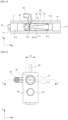
FIG. 2 is a cross-sectional view taken along line A-A ofFIG. 1 . -
FIG 3 is a cross-sectional view taken along line B-B ofFIG. 1 . -
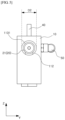
FIG. 4 is a right side view of the venturi nozzle apparatus ofFIG. 1 . -
FIG 5 is a left side view of the venturi nozzle apparatus ofFIG. 1 . -
FIG. 6 is a cross-sectional view taken along line C-C ofFIG. 4 . -
FIG. 7 is a front view illustrating a housing of the venturi nozzle apparatus ofFIG. 1 . -
FIG. 8 is a perspective view illustrating an injector unit of the venturi nozzle apparatus ofFIG. 1 . -
FIG. 9 is a cross-sectional view taken along line D-D ofFIG. 8 . -
FIGS. 10 and11 are operational state views of the venturi nozzle apparatus according to an embodiment of the present invention. - Hereinafter, specific embodiments for implementing the present invention will be described in detail with reference to the accompanying drawings.
- Further, in describing the present invention, when detailed description of a known configuration or function related to the present invention is determined as having the possibility of obscuring the gist of the present invention, the detailed description thereof will be omitted.
- Also, when a certain element is described as being "connected" or "coupled" to another element, it should be understood that the element may be directly connected or coupled to the other element, but another element may also be present therebetween.
- Terms used herein are for describing specific embodiments and are not intended to limit the present invention. A singular expression includes a plural expression unless the context clearly indicates otherwise.
- Also, note that expressions such as "one side" and "the other side" used herein are based on the drawings and may be changed when a direction of the corresponding object is changed. Likewise, some elements in the accompanying drawings may have been exaggerated, omitted, or schematically illustrated, and the size of each element does not necessarily reflect the actual size.
- Also, terms including ordinals such as first and second may be used to describe various elements, but the corresponding elements are not limited by such terms. The terms are only used to distinguish one element from another.
- The terms "comprises", "comprising", "includes", and/or "including", when used herein, specify the presence of stated features, areas, integers, steps, operations, elements, and/or components but do not preclude the presence or addition of one or more other features, areas, integers, steps, operations, elements, components, and/or groups thereof.
- Hereinafter, a specific configuration of a venturi nozzle apparatus according to an embodiment of the present invention will be described with reference to the accompanying drawings.
- Referring to
FIGS. 1 to 9 , aventuri nozzle apparatus 1 according to an embodiment of the present invention may include ahousing 10, aninjector unit 20, avalve member 30, astopper member 40, and agas supply member 50. - The
housing 10 is a member formed in the shape of a hollow quadrangular box, and aflow pipe 11, through which at least one of water and water in which a gas is dissolved selectively flows, and abypass pipe 12, which communicates with theflow pipe 11 to selectively bypass at least one of the water and water in which the gas is dissolved flowing through theflow pipe 11, may be disposed in thehousing 10. - The
flow pipe 11 may be a pipe member provided to cause at least one of the water and water in which the gas is dissolved to flow. Theflow pipe 11 may be formed to extend in one direction. - In this case, the
flow pipe 11 may include asupply end portion 111 which is open to allow the water to be selectively supplied, adischarge end portion 112 which is disposed at a position opposite to thesupply end portion 111 and which is open to allow the water in which the gas is dissolved to be discharged, and a flow pipe sideflow path portion 113 which is provided between thesupply end portion 111 and thedischarge end portion 112 and through which at least one of the water and water in which the gas is dissolved selectively flows. - Meanwhile, a diameter D1 of the
supply end portion 111 may be substantially the same as a diameter D2 of thedischarge end portion 112. Theinjector unit 20 may be inserted through thesupply end portion 111. - Meanwhile, to prevent the
injector unit 20 inserted through thesupply end portion 111 from being detached through thedischarge end portion 112, astep 1131 may be disposed in the flow pipe sideflow path portion 113. Thestep 1131 may be formed due to at least a portion of an inner side surface of the flow pipe sideflow path portion 113 protruding. In this case, thestep 1131 comes in contact with an end portion of theinjector unit 20 inserted through thesupply end portion 111, thus not only preventing theinjector unit 20 from being detached through thedischarge end portion 112 but also blocking the insertion of theinjector unit 20 through thedischarge end portion 112. - The
bypass pipe 12 may be a pipe member provided to bypass at least one of the water and water in which the gas is dissolved flowing through theflow pipe 11. In this case, thebypass pipe 12 may be connected to communicate with theflow pipe 11 through at least one connecting portion and may be disposed to be spaced a predetermined distance apart from theflow pipe 11 in a direction perpendicular to a direction in which theflow pipe 11 extends. - Specifically, the
bypass pipe 12 may include aninsertion end portion 121 which is open to allow thevalve member 30 to be inserted, a closedend portion 122 which is disposed at a position opposite to theinsertion end portion 121 and closed, and a bypass pipe sideflow path portion 123 which is provided between theinsertion end portion 121 and the closedend portion 122 and through which at least one of the water and water in which the gas is dissolved selectively flows. - In this case, when the
valve member 30 is completely inserted into theinsertion end portion 121, an amount of flow in the flow pipe sideflow path portion 113 of theflow pipe 11 is not able to be bypassed to the bypass pipe sideflow path portion 123 of thebypass pipe 12, and when thevalve member 30 completely inserted into theinsertion end portion 121 is separated from theinsertion end portion 121 to an extent that thevalve member 30 is not completely separated from theinsertion end portion 121, at least a portion of the amount of flow in the flow pipe sideflow path portion 113 may be bypassed to the bypass pipe sideflow path portion 123. In this way, as pressure of the water supplied to theinjector unit 20 is changed and pressure of the gas injected from a plurality ofinjection members 23 of theinjector unit 20, which will be described below, varies, a concentration at which the gas is dissolved in the water in theinjector unit 20 may be controlled. - The
injector unit 20 may mix the water and gas to dissolve the gas in the water. To this end, theinjector unit 20 may be detachably inserted into theflow pipe 11 of thehousing 10. In this case, theinjector unit 20 may include amain body 21 which forms an exterior and is replaceably inserted into theflow pipe 11, aventuri member 22 which is disposed inside themain body 21 and has aventuri flow path 221 through which the gas and water are able to be mixed and flow, and the plurality ofinjection members 23 which have one end portion connected to themain body 21 and the other end portion connected to theventuri member 22 and which are disposed to be spaced apart in a circumferential direction of theventuri member 22. - The
main body 21 may include an O-ring insertion portion 211 which has at least a portion of an outer side surface protruding radially inward from themain body 21. The O-ring insertion portion 211 may be formed to extend in a circumferential direction of themain body 21 and may be provided as a plurality of O-ring insertion portions 211. The plurality of O-ring insertion portions 211 may be disposed to be spaced apart at predetermined intervals in a longitudinal direction of themain body 21. In this case, an O-ring member 213 may be fitted to the O-ring insertion portion 211, and due to the O-ring member 213, airtightness between theflow pipe 11 of thehousing 10 and themain body 21 may be maintained. Here, the terms relating to directions will be defined. A direction that is radially inward from themain body 21 refers to a direction from an inner side surface of themain body 21 toward a central portion of themain body 21, the circumferential direction of themain body 21 refers to a direction rotating along an outer circumferential surface of themain body 21, and the longitudinal direction of themain body 21 refers to the x-axis direction ofFIG. 1 . In this case, the circumferential direction of themain body 21 may be any one of clockwise and counter-clockwise when viewed from a side of themain body 21, and unless described otherwise, all of the above directions encompass both positive and negative directions. - Meanwhile, the
main body 21 may include a protrudingportion 212 which has at least a portion of an outer side surface protruding radially inward from themain body 21. Here, a degree to which the protrudingportion 212 protrudes radially inward from themain body 21 may be higher than a degree to which the O-ring insertion portion 211 protrudes radially inward from themain body 21. In this case, the protrudingportion 212 may extend in the circumferential direction of themain body 21 and may be disposed between two O-ring insertion portions 211 adjacent to each other in the longitudinal direction of themain body 21. - Meanwhile, the other end portion of the
injection member 23 may be connected to communicate with an inner side surface of the protrudingportion 212. As the protrudingportion 212 protrudes radially inward from themain body 21, an outer side surface of the protrudingportion 212 and an inner side surface of the flow pipe sideflow path portion 113 may be spaced apart from each other, and thus apredetermined space 2131 may be formed. Thespace 2131 may be used as a space in which a gas supplied from thegas supply member 50 flows, and the gas flowing in thespace 2131 may be supplied to theventuri member 22 through the other end portion of theinjection member 23 connected to the inner side surface of the protrudingportion 212. - The
venturi member 22 may serve to use the venturi effect to form a vortex of water supplied from the outside. To this end, theventuri member 22 may include theventuri flow path 221 in which the gas and water are able to be mixed and flow. - Specifically, the
venturi member 22 may include a first downwardinclined portion 222 which is inclined downward from one end portion toward the other end portion, a second downwardinclined portion 223 which is inclined downward from the other end portion toward one end portion, and aneck portion 224 connected between the first downwardinclined portion 222 and the second downwardinclined portion 223. Here, a cross-sectional area of the first downwardinclined portion 222 may gradually decrease from the one end portion toward the other end portion, and a cross-sectional area of the second downwardinclined portion 223 may gradually decrease from the other end portion toward the one end portion. In this case, the one end portion of theinjection member 23 may be connected to communicate with theneck portion 224. In this way, since theinjection member 23 is connected to communicate with theneck portion 224 in which a flow velocity increases, the water and gas may be smoothly mixed in theventuri flow path 221. - Meanwhile, the amount of flow passing through the
venturi flow path 221 of theventuri member 22 may be determined according to a diameter of one end portion and the other end portion of theventuri member 22. Due to being coupled to an inner portion of a pipe, the conventional venturi member only handles an amount of flow according to a preset diameter of the venturi member. However, since theventuri member 22 according to an embodiment of the present invention is coupled to an inner portion of themain body 21 and themain body 21 is detachably coupled to theflow pipe 11, when it is necessary for theventuri member 22 to correspond to a change in the amount of flow, themain body 21 to which theventuri member 22 having a diameter suitable for the changed amount of flow is coupled is selected and then coupled to theflow pipe 11. In this way, unlike the related art, it is possible to correspond to a change in the amount of flow. - The plurality of
injection members 23 may deliver the gas provided from thegas supply member 50 to theventuri member 22. Also, the plurality ofinjection members 23 may increase a contact area between the water flowing in theventuri member 22 and the gas provided from thegas supply member 50. - To this end, one end portion of the
injection member 23 may be connected to communicate with the protrudingportion 212 of themain body 21, and the other end portion of theinjection member 23 may be connected to communicate with theneck portion 224 of theventuri member 22. Also, the plurality ofinjection members 23 may be disposed to be spaced apart from each other in the circumferential direction of theventuri member 22 and may inject the gas provided from thegas supply member 50 radially inward from theventuri flow path 221 of theventuri member 22. Thus, the water forming a vortex in theventuri flow path 221 and the gas injected radially inward from theventuri flow path 221 collide with each other. In this way, the gas may be efficiently dissolved in the water. - The
valve member 30 may control the concentration at which the gas is dissolved in the water in theinjector unit 20. To this end, thevalve member 30 may be inserted into thebypass pipe 12 of thehousing 10. In this way, thevalve member 30 may cause at least one of the water and water in which the gas is dissolved to flow to at least one of theflow pipe 11 of thehousing 10 and thebypass pipe 12 of thehousing 10. - Meanwhile, the
valve member 30 may be inserted into theinsertion end portion 121 of thebypass pipe 12 of thehousing 10, and according to a degree to which thevalve member 30 is inserted into theinsertion end portion 121, at least one of the water and water in which the gas is dissolved may flow to at least one of theflow pipe 11 of thehousing 10 and thebypass pipe 12 of thehousing 10. For example, thevalve member 30 may be provided as a plug valve, but this is only an example, and the present invention is not limited thereby. - In this case, the
valve member 30 may include an O-ring insertion portion 31 which has at least a portion of an outer side surface protruding radially inward from thevalve member 30. The O-ring insertion portion 31 may be formed to extend in a circumferential direction of thevalve member 30. In this case, an O-ring member 32 may be fitted to the O-ring insertion portion 31, and due to the O-ring member 32, airtightness between thebypass pipe 12 of thehousing 10 and thevalve member 30 may be maintained. - Meanwhile, in the present embodiment, the case in which the
valve member 30 is coupled by being fitted and coupled to theinsertion end portion 121 of thebypass pipe 12 has been described as an example, but this is for convenience of description, and the present invention is not limited thereby. For example, male screw threads may be formed on at least a portion of an outer side surface of thevalve member 30, female screw threads may be formed on at least a portion of an inner side surface of theinsertion end portion 121, and thevalve member 30 and theinsertion end portion 121 may be screw-coupled to each other. - The
stopper member 40 may prevent theinjector unit 20, which is inserted through thesupply end portion 111 of theflow pipe 11, from being detached through thesupply end portion 111 of theflow pipe 11. - To this end, the
stopper member 40 may be selectively inserted into thehousing 10. In this case, at least a portion of thestopper member 40 may be inserted into a stoppermember insertion hole 14 formed in thehousing 10. - In this case, for example, the
stopper member 40 may be provided in the shape of a column that extends in one direction. For example, thestopper member 40 may be inserted into the stoppermember insertion hole 14 after theinjector unit 20 is inserted through thesupply end portion 111 of theflow pipe 11. On the other hand, when it is necessary to replace theinjector unit 20, thestopper member 40 inserted into the stoppermember insertion hole 14 may be separated from the stoppermember insertion hole 14 first, and then theinjector unit 20 inserted into thesupply end portion 111 may be separated from thesupply end portion 111. - Meanwhile, in the present embodiment, the case in which the
stopper member 40 is coupled by being fitted and coupled to the stoppermember insertion hole 14 of thehousing 10 has been described as an example, but the present invention is not limited thereto. For example, male screw threads may be formed on at least a portion of an outer side surface of thestopper member 40, female screw threads may be formed on at least a portion of an inner side surface of the stoppermember insertion hole 14, and thestopper member 40 may be coupled to the stoppermember insertion hole 14 by a screw-coupling method. - The
gas supply member 50 may selectively supply the gas from the outside to theinjector unit 20. To this end, thegas supply member 50 may be provided to be connectable to thehousing 10, and in this case, an end portion of thegas supply member 50 may be inserted into a gas supplymember insertion hole 13 disposed in thehousing 10. - Meanwhile, the
gas supply member 50 may be connected to communicate with theinjection member 23 of theinjector unit 20. The external gas provided through thegas supply member 50 may flow in thespace 2131 formed due to the inner side surface of the flow pipe sideflow path portion 113 and the outer side surface of the protrudingportion 212 being spaced apart from each other, and the gas flowing in thespace 2131 may be supplied to the plurality ofinjection members 23 and injected into theventuri member 22. - Hereinafter, the operation and effects of the
venturi nozzle apparatus 1 having the above-described configuration will be described with reference toFIGS. 10 and11 . - Referring to
FIG. 10 , theinjector unit 20 is inserted through thesupply end portion 111 of theflow pipe 11 disposed in thehousing 10. When insertion of theinjector unit 20 is completed, thestopper member 40 is inserted into the stoppermember insertion hole 14, which is pre-installed in thehousing 10, to prevent theinjector unit 20 from being detached from theflow pipe 11. In this way, installation of theinjector unit 20 in thehousing 10 is completed. - Next, the
gas supply member 50 is connected to the gas supplymember insertion hole 13 which is pre-installed in thehousing 10. - Then, water is supplied from the outside through the
supply end portion 111 of theflow pipe 11. In this case, since thevalve member 30 is completely inserted into theinsertion end portion 121 of thebypass pipe 12 disposed in thehousing 10, the water supplied from the outside can only be supplied to theflow pipe 11 without being bypassed to thebypass pipe 12. - Meanwhile, the water supplied as above flows along the
venturi flow path 221 disposed in theventuri member 22 of theinjector unit 20 and forms a vortex. In this case, the gas provided from thegas supply member 50 is supplied to theventuri flow path 221 through the plurality ofinjection members 23 and is dissolved in the water due to colliding with the vortex of the water. The water in which the gas is dissolved passes through theventuri flow path 221 and is discharged through thedischarge end portion 112 of theflow pipe 11. - Referring to
FIG. 11 , as the degree of insertion of thevalve member 30 which is completely inserted into theinsertion end portion 121 of thebypass pipe 12 is controlled, at least a portion of the water supplied from the outside may be bypassed to thebypass pipe 12. Due to the water bypassed to thebypass pipe 12 in this way, pressure of the water supplied to theventuri flow path 221 of theventuri member 22 may be decreased, and as the amount of gas ejected to theventuri flow path 221 is increased, a concentration at which the gas is dissolved in the water in theventuri flow path 221 may be increased. - A venturi nozzle apparatus according to embodiments of the present invention can be manufactured with a simplified manufacturing process and reduced manufacturing costs and can correspond to a change in the amount of flow.
Claims (8)
- A venturi nozzle apparatus (1) which is configured to mix water and a gas to dissolve the gas in the water, the venturi nozzle apparatus comprising:a housing (10) in which a flow pipe (11), through which at least one of the water and the water in which the gas is dissolved selectively flows, and a bypass pipe (12), which communicates with the flow pipe (11) to selectively bypass at least one of the water and the water in which the gas is dissolved flowing through the flow pipe (11), are disposed;an injector unit (20) which is detachably inserted into the flow pipe (11) of the housing (10) and configured to selectively receive the gas and the water to dissolve the gas in the water; anda valve member (30) which is inserted into the bypass pipe (12) of the housing (10) and configured to cause at least one of the water and the water in which the gas is dissolved to flow to at least one of the flow pipe (11) of the housing (10) and the bypass pipe (12) of the housing (10),wherein the flow pipe (11) includes:a supply end portion (111) which is open to allow the water to be selectively supplied;a discharge end portion (112) which is disposed at a position opposite to the supply end portion (111) and which is open to allow the water in which the gas is dissolved to be discharged; anda flow pipe side flow path portion (113) which is provided between the supply end portion (111) and the discharge end portion (112) and through which at least one of the water and the water in which the gas is dissolved selectively flows,wherein the flow pipe side flow path portion (113) includes a step (1131) which is formed due to at least a portion of an inner side surface protruding, and wherein, as the injector unit (20) inserted through the supply end portion (111) of the flow pipe (11) is caught at the step (1131), the injector unit (20) is prevented from being detached through the discharge end portion (112) of the flow pipe (11),characterised in thatthe venturi nozzle apparatus further comprises a stopper member (40) which is configured to be selectively inserted into the housing (10) to prevent the injector unit (20) inserted through the supply end portion (111) of the flow pipe (11) from being detached through the supply end portion (111) of the flow pipe (11).
- The venturi nozzle apparatus of claim 1, wherein the bypass pipe (12) includes:an insertion end portion (121) which is open to allow the valve member (30) to be inserted;a closed end portion (122) which is disposed at a position opposite to the insertion end portion (121) and closed; anda bypass pipe side flow path portion (123) which is provided between the insertion end portion (121) and the closed end portion (122) and through which at least one of the water and the water in which the gas is dissolved can selectively flow.
- The venturi nozzle apparatus of claim 1, wherein the injector unit (20) includes:a main body (21) which forms an exterior and is replaceably inserted into the flow pipe (11);a venturi member (22) which is disposed inside the main body (21) and has a venturi flow path (221) through which the gas and the water are able to be mixed and flow; anda plurality of injection members (23) which have one end portion connected to the main body (21) and the other end portion connected to the venturi member (22) and which are disposed to be spaced apart in a circumferential direction of the venturi member (22).
- The venturi nozzle apparatus of claim 3, wherein the main body (21) includes a protruding portion (212) which has at least a portion of an outer side surface protruding radially inward from the main body (21) and an inner side surface to which the other end portion of the injection member (23) is connected to communicate, and
the protruding portion (212) extends in a circumferential direction of the main body (21). - The venturi nozzle apparatus of claim 4, further comprising a gas supply member (50) which is provided to be connectable to the housing (10) and connected to communicate with the injection member (23) of the injector unit (20) to selectively supply the gas from the outside to the injector unit (20).
- The venturi nozzle apparatus of claim 5, wherein:
a space (2131) is formed due to the inner side surface of the flow pipe side flow path portion (113) and the outer side surface of the protruding portion (212) being spaced apart from each other to allow the gas provided from the outside through the gas supply member (50) to flow in the space (2131) and to allow the gas flowing in the space (2131) to be supplied to the plurality of injection members (23). - The venturi nozzle apparatus of claim 5, wherein a gas supply member insertion hole (13) into which the gas supply member (50) is selectively inserted is formed in the housing (10).
- The venturi nozzle apparatus of claim 1, wherein a stopper member insertion hole (14) into which the stopper member (40) is selectively inserted is formed in the housing (10).
Applications Claiming Priority (1)
| Application Number | Priority Date | Filing Date | Title |
|---|---|---|---|
| KR1020210064573A KR102526073B1 (en) | 2021-05-20 | 2021-05-20 | Ventury nozzle apparatus |
Publications (3)
| Publication Number | Publication Date |
|---|---|
| EP4091706A1 EP4091706A1 (en) | 2022-11-23 |
| EP4091706C0 EP4091706C0 (en) | 2024-12-04 |
| EP4091706B1 true EP4091706B1 (en) | 2024-12-04 |
Family
ID=78332543
Family Applications (1)
| Application Number | Title | Priority Date | Filing Date |
|---|---|---|---|
| EP21203446.6A Active EP4091706B1 (en) | 2021-05-20 | 2021-10-19 | Venturi nozzle apparatus |
Country Status (6)
| Country | Link |
|---|---|
| US (1) | US12005406B2 (en) |
| EP (1) | EP4091706B1 (en) |
| JP (1) | JP7320855B2 (en) |
| KR (1) | KR102526073B1 (en) |
| CN (1) | CN115382680A (en) |
| TW (1) | TWI795956B (en) |
Families Citing this family (2)
| Publication number | Priority date | Publication date | Assignee | Title |
|---|---|---|---|---|
| CN115875106A (en) * | 2022-12-22 | 2023-03-31 | 马勒汽车技术(中国)有限公司 | Oil mist separator with built-in Venturi tube and oil mist separation system |
| CN117797675A (en) * | 2023-12-26 | 2024-04-02 | 液化空气(中国)投资有限公司 | Gas-liquid injection device and preparation method |
Family Cites Families (26)
| Publication number | Priority date | Publication date | Assignee | Title |
|---|---|---|---|---|
| US2953160A (en) * | 1958-08-20 | 1960-09-20 | Akron Brass Mfg Co Inc | Bypass proportioner |
| US4123800A (en) * | 1977-05-18 | 1978-10-31 | Mazzei Angelo L | Mixer-injector |
| US4344752A (en) * | 1980-03-14 | 1982-08-17 | The Trane Company | Water-in-oil emulsifier and oil-burner boiler system incorporating such emulsifier |
| DE3514833A1 (en) | 1985-04-24 | 1986-11-06 | Siemens AG, 1000 Berlin und 8000 München | INDUCTIVE PROXIMITY SWITCH |
| US4664147A (en) * | 1985-08-06 | 1987-05-12 | Maddock Mitchell E | Flow regulated mixer-injection system |
| PH26721A (en) * | 1986-04-18 | 1992-09-15 | Fluid Techn Ltd | Fluid injection system |
| JPH08155430A (en) | 1994-12-01 | 1996-06-18 | Hidetoshi Kobayashi | Apparatus and method for making activated water and activation of water |
| JP3025804B2 (en) * | 1996-11-25 | 2000-03-27 | 株式会社マンヨー食品 | Water treatment equipment |
| US6623154B1 (en) | 2000-04-12 | 2003-09-23 | Premier Wastewater International, Inc. | Differential injector |
| US20070152355A1 (en) | 2005-12-30 | 2007-07-05 | Hartley John D | Cylindrical insert fluid injector / vacuum pump |
| US8109448B2 (en) * | 2007-11-25 | 2012-02-07 | The Regents Of The University Of California | System and method for at-nozzle injection of agrochemicals |
| EP2277617A1 (en) * | 2009-07-20 | 2011-01-26 | Hayward Industries, Inc. | Combination Venturi check valve |
| WO2015064159A1 (en) | 2013-10-31 | 2015-05-07 | 日之出産業株式会社 | Microbubble formation method, and microbubble formation device |
| US9931601B2 (en) | 2014-07-22 | 2018-04-03 | Hayward Industries, Inc. | Venturi bypass system and associated methods |
| US10183302B2 (en) * | 2015-03-13 | 2019-01-22 | Hong Kun Shin | Micro fogging device and method |
| US10834868B2 (en) | 2015-07-23 | 2020-11-17 | Zachary Lovato | Efficient injection and mixing of chemicals into a fluid delivery system |
| JP2017104841A (en) * | 2015-12-07 | 2017-06-15 | 秀幸 西澤 | Fine bubble generator, and production method of water containing fine bubble |
| DE102017201611B4 (en) | 2017-02-01 | 2018-08-09 | Schott Ag | Apparatus and method for cooling a glass melt contacting component |
| CN208076766U (en) * | 2018-05-02 | 2018-11-09 | 慈溪市华拓光电科技有限公司 | Fiber adapter |
| CN109433035B (en) * | 2018-10-26 | 2021-06-18 | 四川大学 | A venturi-type bubble generating device with multi-venturi structure |
| JP7278799B2 (en) | 2019-02-28 | 2023-05-22 | キヤノン株式会社 | Fine bubble generation device and fine bubble generation method |
| KR102338161B1 (en) * | 2019-07-03 | 2021-12-10 | 경상국립대학교산학협력단 | Spray Gun for Paint and Varnish |
| CN210566348U (en) | 2019-09-04 | 2020-05-19 | 丹鸟机电(苏州)有限公司 | Device for increasing water yield of booster valve |
| KR102276212B1 (en) | 2019-11-26 | 2021-07-12 | 이찬응 | A display stand with increased three-dimensional effect |
| CN111188816B (en) | 2019-12-17 | 2021-11-16 | 中国建筑西北设计研究院有限公司 | Flow distribution method of flow divider based on Venturi effect and flow divider structure |
| CN112317152A (en) | 2020-11-10 | 2021-02-05 | 长安大学 | Adjustable cone ring curtain presses down dirt shower nozzle |
-
2021
- 2021-05-20 KR KR1020210064573A patent/KR102526073B1/en active Active
- 2021-10-19 US US17/505,609 patent/US12005406B2/en active Active
- 2021-10-19 EP EP21203446.6A patent/EP4091706B1/en active Active
- 2021-10-19 JP JP2021171160A patent/JP7320855B2/en active Active
- 2021-10-21 TW TW110139012A patent/TWI795956B/en active
- 2021-10-21 CN CN202111228926.2A patent/CN115382680A/en active Pending
Also Published As
| Publication number | Publication date |
|---|---|
| US12005406B2 (en) | 2024-06-11 |
| EP4091706A1 (en) | 2022-11-23 |
| CN115382680A (en) | 2022-11-25 |
| JP2022179289A (en) | 2022-12-02 |
| JP7320855B2 (en) | 2023-08-04 |
| EP4091706C0 (en) | 2024-12-04 |
| TW202245912A (en) | 2022-12-01 |
| US20220370962A1 (en) | 2022-11-24 |
| TWI795956B (en) | 2023-03-11 |
| KR20220157038A (en) | 2022-11-29 |
| KR102526073B1 (en) | 2023-04-25 |
Similar Documents
| Publication | Publication Date | Title |
|---|---|---|
| EP0639160B1 (en) | Apparatus for dissolving a gas into and mixing the same with a liquid | |
| CN102985172B (en) | Micro bubble generation device based on rotating unit | |
| ES2788743T3 (en) | Atomizing nozzle | |
| US5951922A (en) | Aeration system for substantial bodies of water | |
| CN100382878C (en) | Micro-bubble generator and micro-bubble generator having the same | |
| US8336569B2 (en) | Mixing eductor | |
| US4123800A (en) | Mixer-injector | |
| ES2923851T3 (en) | Loop Flow Bubble Generator Nozzle | |
| US4474477A (en) | Mixing apparatus | |
| KR101483412B1 (en) | Micro bubble nozzle | |
| KR20190084944A (en) | Water Carbonation System and Continuous Water Carbonation Method | |
| US12005406B2 (en) | Venturi nozzle apparatus | |
| JP2018144018A (en) | Liquid treatment nozzle and core element for liquid treatment nozzle | |
| US6165372A (en) | Injection quill for water treatment | |
| ES3058933T3 (en) | Device and method for dispersing gases into liquids | |
| CN223281071U (en) | Detergent throwing device and clothes treatment equipment | |
| KR102446818B1 (en) | melting device | |
| KR20030093374A (en) | coolant mixing and supplying apparatus for machine tools | |
| CN105565448A (en) | Microbubble generator | |
| JP2014033999A (en) | Bubble generating nozzle, and loop flow type bubble generating nozzle | |
| CN106457174A (en) | Gas mixing device | |
| JP6075674B1 (en) | Fluid mixing device | |
| KR102458126B1 (en) | Gas-liquid mixing circulation device capable of removing bubbles therein and dissolution apparatus using the same | |
| US12012737B2 (en) | Effluent dispenser system | |
| JPH04322731A (en) | Method and device for dissolution of gas |
Legal Events
| Date | Code | Title | Description |
|---|---|---|---|
| PUAI | Public reference made under article 153(3) epc to a published international application that has entered the european phase |
Free format text: ORIGINAL CODE: 0009012 |
|
| STAA | Information on the status of an ep patent application or granted ep patent |
Free format text: STATUS: REQUEST FOR EXAMINATION WAS MADE |
|
| 17P | Request for examination filed |
Effective date: 20211019 |
|
| AK | Designated contracting states |
Kind code of ref document: A1 Designated state(s): AL AT BE BG CH CY CZ DE DK EE ES FI FR GB GR HR HU IE IS IT LI LT LU LV MC MK MT NL NO PL PT RO RS SE SI SK SM TR |
|
| GRAP | Despatch of communication of intention to grant a patent |
Free format text: ORIGINAL CODE: EPIDOSNIGR1 |
|
| STAA | Information on the status of an ep patent application or granted ep patent |
Free format text: STATUS: GRANT OF PATENT IS INTENDED |
|
| INTG | Intention to grant announced |
Effective date: 20240517 |
|
| GRAS | Grant fee paid |
Free format text: ORIGINAL CODE: EPIDOSNIGR3 |
|
| GRAA | (expected) grant |
Free format text: ORIGINAL CODE: 0009210 |
|
| STAA | Information on the status of an ep patent application or granted ep patent |
Free format text: STATUS: THE PATENT HAS BEEN GRANTED |
|
| AK | Designated contracting states |
Kind code of ref document: B1 Designated state(s): AL AT BE BG CH CY CZ DE DK EE ES FI FR GB GR HR HU IE IS IT LI LT LU LV MC MK MT NL NO PL PT RO RS SE SI SK SM TR |
|
| REG | Reference to a national code |
Ref country code: CH Ref legal event code: EP |
|
| REG | Reference to a national code |
Ref country code: DE Ref legal event code: R096 Ref document number: 602021022761 Country of ref document: DE |
|
| REG | Reference to a national code |
Ref country code: IE Ref legal event code: FG4D |
|
| U01 | Request for unitary effect filed |
Effective date: 20241217 |
|
| U07 | Unitary effect registered |
Designated state(s): AT BE BG DE DK EE FI FR IT LT LU LV MT NL PT RO SE SI Effective date: 20250110 |
|
| PG25 | Lapsed in a contracting state [announced via postgrant information from national office to epo] |
Ref country code: HR Free format text: LAPSE BECAUSE OF FAILURE TO SUBMIT A TRANSLATION OF THE DESCRIPTION OR TO PAY THE FEE WITHIN THE PRESCRIBED TIME-LIMIT Effective date: 20241204 |
|
| PG25 | Lapsed in a contracting state [announced via postgrant information from national office to epo] |
Ref country code: ES Free format text: LAPSE BECAUSE OF FAILURE TO SUBMIT A TRANSLATION OF THE DESCRIPTION OR TO PAY THE FEE WITHIN THE PRESCRIBED TIME-LIMIT Effective date: 20241204 |
|
| PG25 | Lapsed in a contracting state [announced via postgrant information from national office to epo] |
Ref country code: GR Free format text: LAPSE BECAUSE OF FAILURE TO SUBMIT A TRANSLATION OF THE DESCRIPTION OR TO PAY THE FEE WITHIN THE PRESCRIBED TIME-LIMIT Effective date: 20250305 |
|
| PG25 | Lapsed in a contracting state [announced via postgrant information from national office to epo] |
Ref country code: RS Free format text: LAPSE BECAUSE OF FAILURE TO SUBMIT A TRANSLATION OF THE DESCRIPTION OR TO PAY THE FEE WITHIN THE PRESCRIBED TIME-LIMIT Effective date: 20250304 |
|
| PG25 | Lapsed in a contracting state [announced via postgrant information from national office to epo] |
Ref country code: SM Free format text: LAPSE BECAUSE OF FAILURE TO SUBMIT A TRANSLATION OF THE DESCRIPTION OR TO PAY THE FEE WITHIN THE PRESCRIBED TIME-LIMIT Effective date: 20241204 |
|
| PG25 | Lapsed in a contracting state [announced via postgrant information from national office to epo] |
Ref country code: PL Free format text: LAPSE BECAUSE OF FAILURE TO SUBMIT A TRANSLATION OF THE DESCRIPTION OR TO PAY THE FEE WITHIN THE PRESCRIBED TIME-LIMIT Effective date: 20241204 |
|
| PG25 | Lapsed in a contracting state [announced via postgrant information from national office to epo] |
Ref country code: IS Free format text: LAPSE BECAUSE OF FAILURE TO SUBMIT A TRANSLATION OF THE DESCRIPTION OR TO PAY THE FEE WITHIN THE PRESCRIBED TIME-LIMIT Effective date: 20250404 |
|
| PG25 | Lapsed in a contracting state [announced via postgrant information from national office to epo] |
Ref country code: SK Free format text: LAPSE BECAUSE OF FAILURE TO SUBMIT A TRANSLATION OF THE DESCRIPTION OR TO PAY THE FEE WITHIN THE PRESCRIBED TIME-LIMIT Effective date: 20241204 |
|
| PG25 | Lapsed in a contracting state [announced via postgrant information from national office to epo] |
Ref country code: CZ Free format text: LAPSE BECAUSE OF FAILURE TO SUBMIT A TRANSLATION OF THE DESCRIPTION OR TO PAY THE FEE WITHIN THE PRESCRIBED TIME-LIMIT Effective date: 20241204 |
|
| PLBE | No opposition filed within time limit |
Free format text: ORIGINAL CODE: 0009261 |
|
| STAA | Information on the status of an ep patent application or granted ep patent |
Free format text: STATUS: NO OPPOSITION FILED WITHIN TIME LIMIT |
|
| 26N | No opposition filed |
Effective date: 20250905 |
|
| U20 | Renewal fee for the european patent with unitary effect paid |
Year of fee payment: 5 Effective date: 20251020 |
|
| PGFP | Annual fee paid to national office [announced via postgrant information from national office to epo] |
Ref country code: NO Payment date: 20251027 Year of fee payment: 5 |
|
| PGFP | Annual fee paid to national office [announced via postgrant information from national office to epo] |
Ref country code: TR Payment date: 20251113 Year of fee payment: 5 |