EP4091663B1 - Communication améliorée d'implant à implant pour utilisation avec des dispositifs médicaux implantables - Google Patents
Communication améliorée d'implant à implant pour utilisation avec des dispositifs médicaux implantables Download PDFInfo
- Publication number
- EP4091663B1 EP4091663B1 EP22167396.5A EP22167396A EP4091663B1 EP 4091663 B1 EP4091663 B1 EP 4091663B1 EP 22167396 A EP22167396 A EP 22167396A EP 4091663 B1 EP4091663 B1 EP 4091663B1
- Authority
- EP
- European Patent Office
- Prior art keywords
- imd
- communication
- messages
- communication transceiver
- conductive communication
- Prior art date
- Legal status (The legal status is an assumption and is not a legal conclusion. Google has not performed a legal analysis and makes no representation as to the accuracy of the status listed.)
- Active
Links
Images


Classifications
-
- A—HUMAN NECESSITIES
- A61—MEDICAL OR VETERINARY SCIENCE; HYGIENE
- A61N—ELECTROTHERAPY; MAGNETOTHERAPY; RADIATION THERAPY; ULTRASOUND THERAPY
- A61N1/00—Electrotherapy; Circuits therefor
- A61N1/18—Applying electric currents by contact electrodes
- A61N1/32—Applying electric currents by contact electrodes alternating or intermittent currents
- A61N1/36—Applying electric currents by contact electrodes alternating or intermittent currents for stimulation
- A61N1/372—Arrangements in connection with the implantation of stimulators
- A61N1/37211—Means for communicating with stimulators
- A61N1/37252—Details of algorithms or data aspects of communication system, e.g. handshaking, transmitting specific data or segmenting data
- A61N1/37282—Details of algorithms or data aspects of communication system, e.g. handshaking, transmitting specific data or segmenting data characterised by communication with experts in remote locations using a network
-
- A—HUMAN NECESSITIES
- A61—MEDICAL OR VETERINARY SCIENCE; HYGIENE
- A61N—ELECTROTHERAPY; MAGNETOTHERAPY; RADIATION THERAPY; ULTRASOUND THERAPY
- A61N1/00—Electrotherapy; Circuits therefor
- A61N1/18—Applying electric currents by contact electrodes
- A61N1/32—Applying electric currents by contact electrodes alternating or intermittent currents
- A61N1/36—Applying electric currents by contact electrodes alternating or intermittent currents for stimulation
- A61N1/362—Heart stimulators
- A61N1/365—Heart stimulators controlled by a physiological parameter, e.g. heart potential
- A61N1/368—Heart stimulators controlled by a physiological parameter, e.g. heart potential comprising more than one electrode co-operating with different heart regions
-
- H—ELECTRICITY
- H04—ELECTRIC COMMUNICATION TECHNIQUE
- H04B—TRANSMISSION
- H04B1/00—Details of transmission systems, not covered by a single one of groups H04B3/00 - H04B13/00; Details of transmission systems not characterised by the medium used for transmission
- H04B1/38—Transceivers, i.e. devices in which transmitter and receiver form a structural unit and in which at least one part is used for functions of transmitting and receiving
- H04B1/40—Circuits
-
- A—HUMAN NECESSITIES
- A61—MEDICAL OR VETERINARY SCIENCE; HYGIENE
- A61N—ELECTROTHERAPY; MAGNETOTHERAPY; RADIATION THERAPY; ULTRASOUND THERAPY
- A61N1/00—Electrotherapy; Circuits therefor
- A61N1/02—Details
- A61N1/04—Electrodes
- A61N1/05—Electrodes for implantation or insertion into the body, e.g. heart electrode
- A61N1/0587—Epicardial electrode systems; Endocardial electrodes piercing the pericardium
-
- A—HUMAN NECESSITIES
- A61—MEDICAL OR VETERINARY SCIENCE; HYGIENE
- A61N—ELECTROTHERAPY; MAGNETOTHERAPY; RADIATION THERAPY; ULTRASOUND THERAPY
- A61N1/00—Electrotherapy; Circuits therefor
- A61N1/18—Applying electric currents by contact electrodes
- A61N1/32—Applying electric currents by contact electrodes alternating or intermittent currents
- A61N1/36—Applying electric currents by contact electrodes alternating or intermittent currents for stimulation
- A61N1/362—Heart stimulators
-
- A—HUMAN NECESSITIES
- A61—MEDICAL OR VETERINARY SCIENCE; HYGIENE
- A61N—ELECTROTHERAPY; MAGNETOTHERAPY; RADIATION THERAPY; ULTRASOUND THERAPY
- A61N1/00—Electrotherapy; Circuits therefor
- A61N1/18—Applying electric currents by contact electrodes
- A61N1/32—Applying electric currents by contact electrodes alternating or intermittent currents
- A61N1/36—Applying electric currents by contact electrodes alternating or intermittent currents for stimulation
- A61N1/372—Arrangements in connection with the implantation of stimulators
- A61N1/37211—Means for communicating with stimulators
- A61N1/37217—Means for communicating with stimulators characterised by the communication link, e.g. acoustic or tactile
- A61N1/37223—Circuits for electromagnetic coupling
-
- A—HUMAN NECESSITIES
- A61—MEDICAL OR VETERINARY SCIENCE; HYGIENE
- A61N—ELECTROTHERAPY; MAGNETOTHERAPY; RADIATION THERAPY; ULTRASOUND THERAPY
- A61N1/00—Electrotherapy; Circuits therefor
- A61N1/18—Applying electric currents by contact electrodes
- A61N1/32—Applying electric currents by contact electrodes alternating or intermittent currents
- A61N1/36—Applying electric currents by contact electrodes alternating or intermittent currents for stimulation
- A61N1/372—Arrangements in connection with the implantation of stimulators
- A61N1/37211—Means for communicating with stimulators
- A61N1/37252—Details of algorithms or data aspects of communication system, e.g. handshaking, transmitting specific data or segmenting data
- A61N1/37276—Details of algorithms or data aspects of communication system, e.g. handshaking, transmitting specific data or segmenting data characterised by means for reducing power consumption during telemetry
-
- A—HUMAN NECESSITIES
- A61—MEDICAL OR VETERINARY SCIENCE; HYGIENE
- A61N—ELECTROTHERAPY; MAGNETOTHERAPY; RADIATION THERAPY; ULTRASOUND THERAPY
- A61N1/00—Electrotherapy; Circuits therefor
- A61N1/18—Applying electric currents by contact electrodes
- A61N1/32—Applying electric currents by contact electrodes alternating or intermittent currents
- A61N1/36—Applying electric currents by contact electrodes alternating or intermittent currents for stimulation
- A61N1/372—Arrangements in connection with the implantation of stimulators
- A61N1/37211—Means for communicating with stimulators
- A61N1/37252—Details of algorithms or data aspects of communication system, e.g. handshaking, transmitting specific data or segmenting data
- A61N1/37288—Communication to several implantable medical devices within one patient
-
- A—HUMAN NECESSITIES
- A61—MEDICAL OR VETERINARY SCIENCE; HYGIENE
- A61N—ELECTROTHERAPY; MAGNETOTHERAPY; RADIATION THERAPY; ULTRASOUND THERAPY
- A61N1/00—Electrotherapy; Circuits therefor
- A61N1/18—Applying electric currents by contact electrodes
- A61N1/32—Applying electric currents by contact electrodes alternating or intermittent currents
- A61N1/36—Applying electric currents by contact electrodes alternating or intermittent currents for stimulation
- A61N1/372—Arrangements in connection with the implantation of stimulators
- A61N1/375—Constructional arrangements, e.g. casings
- A61N1/3756—Casings with electrodes thereon, e.g. leadless stimulators
-
- A—HUMAN NECESSITIES
- A61—MEDICAL OR VETERINARY SCIENCE; HYGIENE
- A61N—ELECTROTHERAPY; MAGNETOTHERAPY; RADIATION THERAPY; ULTRASOUND THERAPY
- A61N1/00—Electrotherapy; Circuits therefor
- A61N1/18—Applying electric currents by contact electrodes
- A61N1/32—Applying electric currents by contact electrodes alternating or intermittent currents
- A61N1/36—Applying electric currents by contact electrodes alternating or intermittent currents for stimulation
- A61N1/372—Arrangements in connection with the implantation of stimulators
- A61N1/378—Electrical supply
- A61N1/3787—Electrical supply from an external energy source
-
- A—HUMAN NECESSITIES
- A61—MEDICAL OR VETERINARY SCIENCE; HYGIENE
- A61N—ELECTROTHERAPY; MAGNETOTHERAPY; RADIATION THERAPY; ULTRASOUND THERAPY
- A61N1/00—Electrotherapy; Circuits therefor
- A61N1/18—Applying electric currents by contact electrodes
- A61N1/32—Applying electric currents by contact electrodes alternating or intermittent currents
- A61N1/38—Applying electric currents by contact electrodes alternating or intermittent currents for producing shock effects
- A61N1/39—Heart defibrillators
- A61N1/3956—Implantable devices for applying electric shocks to the heart, e.g. for cardioversion
-
- H—ELECTRICITY
- H04—ELECTRIC COMMUNICATION TECHNIQUE
- H04W—WIRELESS COMMUNICATION NETWORKS
- H04W4/00—Services specially adapted for wireless communication networks; Facilities therefor
- H04W4/30—Services specially adapted for particular environments, situations or purposes
-
- H—ELECTRICITY
- H04—ELECTRIC COMMUNICATION TECHNIQUE
- H04W—WIRELESS COMMUNICATION NETWORKS
- H04W4/00—Services specially adapted for wireless communication networks; Facilities therefor
- H04W4/80—Services using short range communication, e.g. near-field communication [NFC], radio-frequency identification [RFID] or low energy communication
Definitions
- Embodiments described herein generally relate to devices, and systems for providing and improving communication between implantable medical devices, one or more of which may be a leadless pacemaker.
- Implantable medical devices and systems often rely on proper communication to operate correctly.
- implant-to-implant (i2i) communication between two or more leadless pacemakers (LPs) is critical for proper synchronization and operation of the system.
- the LPs can communicate with one another using conductive communication, or using i2i radio frequency (RF) communication.
- Conductive communication involves transmitting and receiving communication signals through patient tissue, typically using the same electrodes that are used for cardiac pacing and sensing, wherein the transmitted communication signals include pulses that can be produced using the same pulse generator that is used to produce pacing pulses.
- RF communication by contrast, involves using an antenna for transmitting and receiving RF communication signals.
- Conductive communication which is also known as conducted communication, or galvanic communication, is much more energy efficient than RF communication. Accordingly, the longevity of a dual chamber LP system that utilizes conducted communication for i2i communication is greater than the longevity of a dual chamber LP system that utilizes RF communication for i2i communication.
- one potential problem with relying on conducted communication for i2i communication between LPs, between an LP and another type of implantable medical device (IMD), or more generally between IMDs is that conducted communication may be adversely affected by noise from a magnetic resonance imaging (MRI) system, or some other noise source.
- MRI magnetic resonance imaging
- a dual chamber LP system may switch from a DOO mode to a VOO mode if it is known that the LPs are about to be exposed to an MRI scan, or in response to a noise reversion trigger.
- US 2020/352441 discloses an implantable device to reliably record and transmit physiological signals from a subject. Design of the device to capture the signals, compress them, transmit via multiple techniques and to interpret the data are shown. Furthermore, the design and operation of the device in a typical setting are taught and the resulting implementation is presented.
- US 2021/093873 discloses IMDs and methods for use therewith to reduce how often an IMD accepts a false message and/or reduce adverse effects of an IMD accepting a false message. Such embodiments can be used help multiple IMDs implanted within a same patient maintain synchronous operation, such as synchronous multi-chamber pacing.
- US 2018/168460 discloses a method for monitoring a cardiovascular pressure in a patient by measuring, by pressure sensing circuitry of an implantable pressure sensing device, the cardiovascular pressure of the patient. The method further includes transmitting, via wireless communication circuitry of the implantable pressure sensing device, the measured cardiovascular pressure to another device. The method further includes determining, by processing circuitry of the other device, whether a posture of the patient at a time of the measured cardiovascular pressure was a target posture for cardiovascular pressure measurements. The method further includes determining, by the processing circuitry of the other device, whether to store or discard the transmitted cardiovascular pressure based on determining whether the posture was the target posture.
- US 2016/144190 discloses an implantable medical device system with an extracardiac sensing device and an intracardiac pacemaker.
- the sensing device senses a P-wave attendant to an atrial depolarization of the heart via housing-based electrodes carried by the sensing device when the sensing device is implanted outside the cardiovascular system and sends a trigger signal to the intracardiac pacemaker in response to sensing the P-wave.
- the intracardiac pacemaker detects the trigger signal and schedules a ventricular pacing pulse in response to the detected trigger signal.
- IMDs implantable medical devices
- i2i implant-to-implant communication between the IMDs
- LP leadless pacemaker
- pacing and sensing operations can be performed by multiple medical devices, which may include one or more leadless cardiac pacemakers, a non-vascular ICD, such as a subcutaneous-ICD (S-ICD), and/or a programmer to reliably and safely coordinate pacing and/or sensing operations.
- a leadless cardiac pacemaker can also be referred to more succinctly herein as a leadless pacemaker (LP).
- a cardiac pacing system includes a non-vascular ICD (e.g., an S-ICD)
- the non-vascular ICD may perform certain sensing operations and may communicate with one or more LPs by sending and/or receiving messages to and/or from one or more LPs, as can be appreciated from the below discussion.
- the programmer may be used to program one or more IMDs, download information to one or more IMDs, and/or upload information from one or more IMDs, as can be appreciated from the below description.
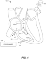
- FIG. 1 illustrates a system 100 that is configured to be implanted in a heart 101.
- the system 100 includes two or more leadless pacemakers (LPs) 102a and 102b located in different chambers of the heart.
- LP 102a is located in a right atrium, while LP 102b is located in a right ventricle.
- LPs 102a and 102b communicate with one another to inform one another of various local physiologic activities, such as local intrinsic events, local paced events and the like.
- LPs 102a and 102b may be constructed in a similar manner, but operate differently based upon which chamber the LP 102a or 102b is located.
- the LPs 102a and 102b may sometimes be referred to collectively herein as the LPs 102, or individually as an LP 102.
- LPs 102a and 102b communicate with one another, and/or with an ICD 106, by conductive communication through the same electrodes that are used for sensing and/or delivery of pacing therapy.
- the LPs 102a and 102b may also be able to use conductive communication to communicate with an external device, e.g., a programmer 109, having electrodes placed on the skin of a patient within with the LPs 102a and 102b are implanted.
- the LPs 102a and 102b can each also include an antenna that would enable them to communicate with one another, the ICD 106 and/or an external device using RF communication. While only two LPs are shown in FIG.
- LPs can be implanted in a patient.
- CRT cardiac resynchronization therapy
- a further LP can be implanted in the left ventricular (LV) chamber.
- one or more LP 102 can be co-implanted with the ICD 106.
- Each LP 102 uses two or more electrodes located within, on, or within a few centimeters of the housing of the pacemaker, for pacing and sensing at the cardiac chamber, for bidirectional conductive communication with one another, with the programmer 109, and the ICD 106.
- the devices and systems described herein include examples primarily in the context of LPs, it is understood that the devices and systems described herein may be utilized with various other types of IMDs.
- the devices and systems may be used to improve communication between various IMDs implanted in a human, not just LPs.
- such embodiments can be used to improve communications between at least two LPs, between an LP and an NV-ICD, between an LP and an ICM, between an ICM and an S-ICD, but are not limited thereto.
- the embodiments described herein can be used to improve communication between more than two IMDs, and are not limited to communication between just first and second IMDs.
- the devices and systems may also be used to improve communication between two or more IMDs implanted within the same cardiac chamber that may be the same type of IMD or may be different types of IMDs.
- the devices and systems may also be used to improve communication between two or more IMDs in a system including at least one IMD that is not implanted within a cardiac chamber, but rather, is implanted epicardially, transmurally, intravascularly (e.g., coronary sinus), or subcutaneously (e.g., S-ICD), etc.
- a block diagram shows an embodiment for portions of the electronics within LPs 102a, 102b configured to provide conductive communication through the sensing/pacing electrode.
- LPs 102a and 102b include at least two leadless electrodes configured for delivering cardiac pacing pulses, sensing evoked and/or natural cardiac electrical signals, and uni-directional or bi-directional conductive communication.
- the two electrodes shown therein are labeled 108a and 108b.
- Such electrodes can be referred to collectively as the electrodes 108, or individually as an electrode 108.
- An LP 102, or other type of IMD can include more than two electrodes 108, depending upon implementation.
- each of the LPs 102a, 102b is shown as including first and second receivers 120 and 122 that collectively define separate first and second conductive communication channels 105 and 107 ( FIG. 1 ), (among other things) between LPs 102a and 102b.
- first and second receivers 120 and 122 are depicted, in other embodiments, each LP 102a, 102b may only include the first receiver 120, or more generally may include only a single receiver that is configured to receive conductive communication signals. It is also possible that an LP 102 may include additional receivers other than first and second receivers 120 and 122.
- the pulse generator 116 can function as a transmitter that transmits i2i communication signals using the electrodes 108.
- LPs 102a and 102b may communicate over more than just first and second conductive communication channels 105 and 107.
- LPs 102a and 102b may communicate over one common communication channel 105. More specifically, LPs 102a and 102b can communicate conductively over a common physical channel via the same electrodes 108 that are also used to deliver pacing pulses.
- the receivers 120 and 122 can also be referred to, respectively, as a low frequency (LF) receiver 120 and a high frequency (HF) receiver 122, because the receiver 120 is configured to monitor for one or more signals within a relatively low frequency range (e.g., below 100 KHz) and the receiver 122 is configured to monitor for one or more signals within a relatively high frequency range (e.g., above 100 KHz).
- the receiver 120 (and more specifically, at least a portion thereof) is always enabled and monitoring for a wakeup notice, which can simply be a wakeup pulse, within a specific low frequency range (e.g., between 1 KHz and 100 KHz); and the receiver 122 is selectively enabled by the receiver 120.
- the receiver 120 is configured to consume less power than the receiver 122 when both the first and second receivers are enabled. Accordingly, the receiver 120 can also be referred to as a low power receiver 120, and the receiver 122 can also be referred to as a high power receiver 122.
- the low power receiver 120 is incapable of receiving signals within the relatively high frequency range (e.g., above 100 KHz), but consumes significantly less power than the high power receiver 122. This way the low power receiver 120 is capable of always monitoring for a wakeup notice without significantly depleting the battery (e.g., 114) of the LP.
- the high power receiver 122 is selectively enabled by the low power receiver 120, in response to the low power receiver 120 receiving a wakeup notice, so that the high power receiver 122 can receive the higher frequency signals, and thereby handle higher data throughput needed for effective i2i communication without unnecessarily and rapidly depleting the battery of the LP (which the high power receiver 122 may do if it were always enabled).
- each of the LPs 102 includes only a single conductive communication receiver.
- the corresponding LP 102a, 102b transmits an implant event message to the other LP 102a, 102b.
- the atrial LP 102a senses/paces an atrial event
- the atrial LP 102a transmits an implant event message including an event marker indicative of a nature of the event (e.g., intrinsic/sensed atrial event, paced atrial event).
- each LP 102a, 102b transmits an implant event message to the other LP 102a, 102b preceding the actual pace pulse so that the remote LP can blank its sense inputs in anticipation of that remote pace pulse (to prevent inappropriate crosstalk sensing).
- implant event messages are examples of i2i messages.
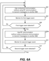
- each event message may include a leading trigger pulse (also referred to as an LP wakeup notice, wakeup pulse or wakeup signal) followed by an event marker.
- the notice trigger pulse (also referred to as the wakeup notice, wakeup pulse or wakeup signal) is transmitted over a first channel (e.g., with a pulse duration of approximately 10 ⁇ s to approximately 1ms and/or within a fundamental frequency range of approximately 1 KHz to approximately 100 KHz).
- the notice trigger pulse indicates that an event marker is about to be transmitted over a second channel (e.g., within a higher frequency range). The event marker can then be transmitted over the second channel.
- the event markers may include data indicative of one or more events (e.g., a sensed intrinsic atrial activation for an atrial located LP, a sensed intrinsic ventricular activation for a ventricular located LP).
- the event markers may include different markers for intrinsic and paced events.
- the event markers may also indicate start or end times for timers (e.g., an AV interval, a blanking interval, etc.).
- the implant event message may include a message segment that includes additional/secondary information.
- the LP (or other IMD) that receives any i2i communication message from another LP (or other IMD) or from an external device may transmit a receive acknowledgement indicating that the receiving LP (or other IMD) received the i2i communication message.
- the IMD may transmit a failure-to-receive acknowledgement indicating that the receiving IMD failed to receive the i2i communication message.
- an LP can receive a message from another LP that includes an indicator (e.g., an error code) in its payload, or header, that indicates to the LP that the other LP failed to receive an expected message from the LP.
- an indicator e.g., an error code
- the event messages enable the LPs 102a, 102b to deliver synchronized therapy and additional supportive features (e.g., measurements, etc.).
- additional supportive features e.g., measurements, etc.
- each of the LPs 102a and 102b is made aware (through the event messages) when an event occurs in the chamber containing the other LP 102a, 102b.
- Some embodiments described herein provide efficient and reliable processes to maintain synchronization between LPs 102a and 102b without maintaining continuous communication between LPs 102a and 102b.
- low power event messages/signaling may be maintained between LPs 102a and 102b synchronously or asynchronously.
- LPs 102a and 102b may maintain synchronization and regularly communicate at a specific interval. Synchronous event signaling allows the transmitter and receivers in each LP 102a, 102b to use limited (or minimal) power as each LP 102a, 102b is only powered for a small fraction of the time in connection with transmission and reception. For example, LP 102a, 102b may transmit/receive (Tx/Rx) communication messages in time slots having duration of 10-20 ⁇ s, where the Tx/Rx time slots occur periodically (e.g., every 10-20ms).
- Tx/Rx time slots having duration of 10-20 ⁇ s
- LPs 102a and 102b may lose synchronization, even in a synchronous event signaling scheme.
- features may be included in LPs 102a and 102b to maintain device synchronization, and when synchronization is lost, LPs 102a and 102b undergo operations to recover synchronization.
- synchronous event messages/signaling may introduce a delay between transmissions which causes a reaction lag at the receiving LP 102a, 102b. Accordingly, features may be implemented to account for the reaction lag.
- LPs 102a and 102b do not maintain communication synchronization.
- one or more of receivers 120 and 122 of LPs 102a and 102b may be "always on” (always awake) to search for incoming transmissions.
- maintaining LP receivers 120, 122 in an "always on” (always awake) state presents challenges as the received signal level often is low due to high channel attenuation caused by the patient's anatomy. Further, maintaining the receivers awake will deplete the battery 114 more quickly than may be desirable.
- the asynchronous event signaling methods avoid risks associated with losing synchronization between devices.
- the asynchronous event signaling methods utilize additional receiver current between transmissions.
- the channel attenuation may be estimated to have a gain of 1/500 to 1/10000.
- a gain factor may be 1/1000th.
- Transmit current is a design factor in addition to receiver current.
- the system may allocate one-half of the implant communication current budget to the transmitter (e.g., 0.5 ⁇ A for each transmitter).
- a transmitted voltage may be 2.5V.
- the event signal is attenuated as it propagates and would appear at LP 102a, 102b receiver as an amplitude of approximately 0.25mV.
- a pulsed transmission scheme may be utilized in which communication transmissions occur correlated with an event.
- the pulsed transmission scheme may be simplified such that each transmission constitutes a single pulse of a select amplitude and width.
- LPs 102a and 102b may utilize multi-stage receivers that implement a staged receiver wakeup scheme in order to improve reliability yet remain power efficient.
- Each of LPs 102a and 102b may include first and second receivers 120 and 122 that operate with different first and second activation protocols and different first and second receive channels.
- first receiver 120 may be assigned a first activation protocol that is "always on” (also referred to as always awake) and that listens over a first receive channel that has a lower fundamental frequency range/pulse duration (e.g., 1 KHz to 100 KHz 110 ⁇ s to approximately 1 ms) as compared to the fundamental frequency range (e.g., greater than 100 KHz / less than 10 ⁇ s per pulse) assigned to the second receive channel.
- fundamental frequency range/pulse duration e.g., 1 KHz to 100 KHz 110 ⁇ s to approximately 1 ms
- the fundamental frequency range e.g., greater than 100 KHz / less than 10 ⁇ s per pulse
- the first receiver 120 may maintain the first channel active (awake) at all times (including when the second channel is inactive (asleep)) in order to listen for messages from a remote LP.
- the second receiver 122 may be assigned a second activation protocol that is a triggered protocol, in which the second receiver 122 becomes active (awake) in response to detection of trigger events over the first receive channel (e.g., when the incoming signal corresponds to the LP wakeup notice, activating the second channel at the local LP).
- the terms active, turned on, awake and enabled are used interchangeably herein.
- each LP 102a, 102b is shown as including a controller 112 and a pulse generator 116.
- the controller 112 can include, e.g., a microprocessor (or equivalent control circuitry), RAM and/or ROM memory, logic and timing circuitry, state machine circuitry, and I/O circuitry, but is not limited thereto.
- the controller 112 can further include, e.g., timing control circuitry to control the timing of the stimulation pulses (e.g., pacing rate, atrio-ventricular (AV) delay, atrial interconduction (A-A) delay, or ventricular interconduction (V-V) delay, etc.).
- pacing rate e.g., pacing rate, atrio-ventricular (AV) delay, atrial interconduction (A-A) delay, or ventricular interconduction (V-V) delay, etc.
- AV atrio-ventricular
- A-A atrial interconduction
- V-V ventricular interconduction
- Such timing control circuitry may also be used for the timing of refractory periods, blanking intervals, noise detection windows, evoked response windows, alert intervals, marker channel timing, and so on.
- the controller 112 can further include other dedicated circuitry and/or firmware/software components that assist in monitoring various conditions of the patient's heart and managing pacing therapies.
- the controller 112 can include an arrhythmia detector, which can be similar to the arrhythmia detector 834 discussed below with reference to FIG. 8 .
- the controller 112 and the pulse generator 116 may be configured to transmit event messages, via the electrodes 108, in a manner that does not inadvertently capture the heart in the chamber where LP 102a, 102b is located, such as when the associated chamber is not in a refractory state.
- an LP 102a, 102b that receives an event message may enter an "event refractory" state (or event blanking state) following receipt of the event message.
- the event refractory/blanking state may be set to extend for a determined period of time after receipt of an event message in order to avoid the receiving LP 102a, 102b from inadvertently sensing another signal as an event message that might otherwise cause retriggering.
- the receiving LP 102a, 102b may detect a measurement pulse from another LP 102a, 102b or the programmer 109.
- the conductive communication transceiver 124 can alternatively include alternative and/or additional components that enable an LP, or other type of IMD, to transmit and receive conductive communication messages with another IMD and/or with an external device, such as the programmer 109.
- the same pulse generator 116 can be used to produce pacing pulses (for use in pacing a patient's heart) and conductive communication pulses (for use in communicating with another IMD or an external device), it would also be possible that the conductive communication transceiver 124 can include its own dedicated pulse generator. For another example, as noted above, it would also be possible for the conductive communication transceiver 124 to include only a single receiver, rather than both receivers 120, 122. Other variations are also possible and within the scope of the embodiments described herein.
- the LP 102 is also shown as including an antenna 118 that is coupled to a radio frequency (RF) communication transceiver 134, which is configured to transmit and receive RF communication messages using an RF communication protocol, such as a Bluetooth protocol, WiFi protocol, Bluetooth low energy (BLE) protocol, Medical Device Radiocommunications Service (MedRadio) protocol, and/or the like.
- RF radio frequency
- the antenna 118 can be integrated into a fixation mechanism (e.g., 205) of the LP, in which case the antenna can be referred to as a fixation antenna.
- a fixation antenna is disclosed in U.S. Patent No. 10,583,300 , titled "Leadless implantable medical device with fixation antenna member".
- the antenna 118 is separate and distinct from the fixation mechanism of the LP 102.
- the specific type, location and formfactor of the antenna may depend on the specific type and formfactor of the IMD.
- the RF communication transceiver 134 consumes more battery power than the conductive communication transceiver 124. More generally, it is more power efficient from an LP 102 (or other type of IMD) to use conductive communication than to use RF communication to communicate with another LP 102 (or other type of IMD). Accordingly, in accordance with certain embodiments of the present technology, the LP 102 (or other type of IMD) is configured to primarily transmit and receive messages using conductive communication, and RF communication is used as a backup or auxiliary type of communication that can be used when conductive communication is deactivated (aka turned off) or is unsuccessful or otherwise deficient, as will be described in additional detail below.
- the programmer 109 may communicate over a programmer-to-LP channel, with LP 102a, 102b utilizing the same communication scheme.
- the external programmer 109 may listen to the event message transmitted between LP 102a, 102b and synchronize programmer to implant communication such that programmer 109 does not transmit communication messages 113 until after an i2i messaging sequence is completed.
- LP 102a, 102b may combine transmit operations with therapy.
- the transmit event marker may be configured to have similar characteristics in amplitude and pulse-width to a pacing pulse and LP 102a, 102b may use the energy in the event messages to help capture the heart.
- a pacing pulse may normally be delivered with pacing parameters of 2.5V amplitude, 500 ohm impedance, 60 bpm pacing rate, 0.4 ms pulse-width.
- the foregoing pacing parameters correspond to a current draw of about 1.9 ⁇ A.
- the same LP 102a, 102b may implement an event message utilizing event signaling parameters for amplitude, pulse-width, pulse rate, etc. that correspond to a current draw of approximately 0.5 ⁇ A for transmit.
- LP 102a, 102b may combine the event message transmissions with pacing pulses.
- LP 102a, 102b may use a 50 ⁇ s wakeup transmit pulse having an amplitude of 2.5V which would draw 250nC (nano Coulombs) for an electrode load of 500 ohm.
- the pulses of the transmit event message may be followed by an event message encoded with a sequence of short duration pulses (for example 16, 2 ⁇ s on/off bits) which would draw an additional 80nC.
- the event message pulse would then be followed by the remaining pulse-width needed to reach an equivalent charge of a nominal 0.4ms pace pulse.
- the current necessary to transmit the marker is essentially free as it was used to achieve the necessary pace capture anyhow. With this method, the savings in transmit current could be budgeted for the receiver or would allow for additional longevity.
- LP 102a or 102b When LP 102a or 102b senses an intrinsic event, it can send a qualitatively similar event pulse sequence (but indicative of a sensed event) without adding the pace pulse remainder. As LP 102a, 102b longevity calculations are designed based on the assumption that LP 102a, 102b will deliver pacing therapy 100% of the time, transmitting an intrinsic event marker to another LP 102a, 102b will not impact the nominal calculated LP longevity.
- LP 102a, 102b may deliver pacing pulses at relatively low amplitude.
- the power budget for event messages may be modified to be a larger portion of the overall device energy budget.
- LP 102a, 102b increases an extent to which LP 102a, 102b uses the event messages as part of the pacing therapy (also referred to as sharing "capture charge” and "transmit charge”).
- the nominal pacing voltage can be lowered to ⁇ 1.25 V
- a "supply halving" pacing charge circuit could reduce the battery current draw by approximately 50%.
- a 1.25V pace pulse would save 1.5 ⁇ A of pacing current budget.
- LP 102a, 102b may use larger pulse-widths.
- LP 102a, 102b may realize additional longevity.
- Today longevity standards provide that the longevity to be specified based on a therapy that utilizes 2.5V amplitude, 0.4ms pulses at 100% pacing.
- a new standard may be established based on pacing pulses that deliver lower amplitude and/or shorter pacing pulses.
- a communication capacitor can be provided in LP 102a, 102b.
- the communication capacitor may be used to transmit event signals having higher voltage for the event message pulses to improve communication, such as when the LPs 102a and 102b experience difficulty sensing event messages.
- the high voltage event signaling may be used for implants with high signal attenuation or in the case of a retry for an ARQ (automatic repeat request) handshaking scheme.
- each individual LP 102 can comprise a hermetic housing 110 configured for placement on or attachment to the inside or outside of a cardiac chamber and at least two leadless electrodes 108 proximal to the housing 110 and configured for bidirectional communication with at least one other device (e.g., an NV-ICD 106) within or outside the body.
- a hermetic housing 110 configured for placement on or attachment to the inside or outside of a cardiac chamber and at least two leadless electrodes 108 proximal to the housing 110 and configured for bidirectional communication with at least one other device (e.g., an NV-ICD 106) within or outside the body.
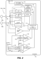
- FIG. 2 depicts a single LP 102 (e.g., the LP 102a or 102b) and shows the LP's functional elements substantially enclosed in a hermetic housing 110.
- the LP 102 has at least two electrodes 108 located within, on, or near the housing 110, for delivering pacing pulses to and sensing electrical activity from the muscle of the cardiac chamber, and for bidirectional communication with at least one other device within or outside the body.
- Hermetic feedthroughs 130, 131 conduct electrode signals through the housing 110.
- the housing 110 contains a primary battery 114 to supply power for pacing, sensing, and communication.
- the housing 110 also contains circuits 132 for sensing cardiac activity from the electrodes 108, receivers 120, 122 for receiving information from at least one other device via the electrodes 108, and the pulse generator 116 for generating pacing pulses for delivery via the electrodes 108 and also for transmitting information to at least one other device via the electrodes 108.
- the housing 110 can further contain circuits for monitoring device health, for example a battery current monitor 136 and a battery voltage monitor 138, and can contain circuits for controlling operations in a predetermined manner.
- the electrodes 108 can be configured to communicate bidirectionally among the multiple leadless cardiac pacemakers and/or the implanted ICD 106 to coordinate pacing pulse delivery and optionally other therapeutic or diagnostic features using messages that identify an event at an individual pacemaker originating the message and a pacemaker receiving the message react as directed by the message depending on the origin of the message.
- An LP 102a, 102b that receives the event message reacts as directed by the event message depending on the message origin or location.
- the two or more leadless electrodes 108 can be configured to communicate bidirectionally among the one or more leadless cardiac pacemakers 102 and/or the ICD 106 and transmit data including designated codes for events detected or created by an individual pacemaker. Individual pacemakers can be configured to issue a unique code corresponding to an event type and a location of the sending pacemaker.
- an individual LP 102a, 102b can be configured to deliver a pacing pulse with an event message encoded therein, with a code assigned according to pacemaker location and configured to transmit a message to one or more other leadless cardiac pacemakers via the event message coded pacing pulse.
- the pacemaker or pacemakers receiving the message are adapted to respond to the message in a predetermined manner depending on type and location of the event.
- information communicated on the incoming channel can also include an event message from another leadless cardiac pacemaker signifying that the other leadless cardiac pacemaker has sensed a heartbeat or has delivered a pacing pulse, and identifies the location of the other pacemaker.
- LP 102b may receive and relay an event message from LP 102a to the programmer.
- information communicated on the outgoing channel can also include a message to another leadless cardiac pacemaker or pacemakers, or to the ICD, that the sending leadless cardiac pacemaker has sensed a heartbeat or has delivered a pacing pulse at the location of the sending pacemaker.
- the cardiac pacing system 100 may comprise an ICD 106 in addition to one or more LPs 102a, 102b configured for implantation in electrical contact with a cardiac chamber and for performing cardiac rhythm management functions in combination with the implantable ICD 106.
- the implantable ICD 106 and the one or more LPs 102a, 102b configured for leadless intercommunication by information conduction through body tissue and/or wireless transmission between transmitters and receivers in accordance with the embodiments discussed herein.
- a cardiac pacing system 100 comprises at least one LP 102a, 102b configured for implantation in electrical contact with a cardiac chamber and configured to perform cardiac pacing functions in combination with the co-implanted ICD 106.
- Each LP 102 comprise at least two leadless electrodes 108 configured for delivering cardiac pacing pulses, sensing evoked and/or natural cardiac electrical signals, and transmitting information to the co-implanted ICD 106.
- an LP 102a, 102b can comprise two or more leadless electrodes 108 configured for delivering cardiac pacing pulses, sensing evoked and/or natural cardiac electrical signals, and bidirectionally communicating with the co-implanted ICD 106.
- Each LP 102a, 102b can be configured for operation in a respective particular location and to have a respective particular functionality at manufacture and/or by programming by an external programmer.
- Bidirectional communication among the multiple leadless cardiac pacemakers can be arranged to communicate notification of a sensed heartbeat or delivered pacing pulse event and encoding type and location of the event to another implanted pacemaker or pacemakers.
- the LP 102a, 102b receiving the communication decode the information and respond depending on location of the receiving pacemaker and predetermined system functionality.
- the LPs 102a and 102b are configured to be implantable in any chamber of the heart, namely either atrium (RA, LA) or either ventricle (RV, LV). Furthermore, for dual-chamber configurations, multiple LPs may be co-implanted (e.g., one in the RA and one in the RV, one in the RV and one in the coronary sinus proximate the LV). Certain pacemaker parameters and functions depend on (or assume) knowledge of the chamber in which the pacemaker is implanted (and thus with which the LP is interacting; e.g., pacing and/or sensing).
- each LP needs to know an identity of the chamber in (or on) which the LP is implanted, and processes may be implemented to automatically identify a local chamber associated with each LP.
- Processes for chamber identification may also be applied to subcutaneous pacemakers, ICDs, with leads and the like.
- a device with one or more implanted leads, identification and/or confirmation of the chamber into which the lead was implanted could be useful in several pertinent scenarios. For example, for a DR or CRT device, automatic identification and confirmation could mitigate against the possibility of the clinician inadvertently placing the V lead into the A port of the implantable medical device, and vice-versa.
- automatic identification of implanted chamber could enable the device and/or programmer to select and present the proper subset of pacing modes (e.g., AAI or VVI), and for the IPG to utilize the proper set of settings and algorithms (e.g., V-AutoCapture vs ACap-Confirm, sensing sensitivities, etc.).
- the proper subset of pacing modes e.g., AAI or VVI
- the IPG to utilize the proper set of settings and algorithms (e.g., V-AutoCapture vs ACap-Confirm, sensing sensitivities, etc.).
- the primary battery 114 has positive terminal 140 and negative terminal 142. Current from the positive terminal 140 of primary battery 114 flows through a shunt 144 to a regulator circuit 146 to create a positive voltage supply 148 suitable for powering the remaining circuitry of the pacemaker 102.
- the shunt 144 enables the battery current monitor 136 to provide the controller 112 with an indication of battery current drain and indirectly of device health.
- the illustrative power supply can be a primary battery 114.
- the LP is shown as including a temperature sensor 152.
- the temperature sensor can be any one of various different types of well-known temperature sensors, or can be a future developed temperature sensor.
- the temperature sensor 152 can be a thermistor, a thermocouple, a resistance thermometer, or a silicon bandgap temperature sensor, but is not limited thereto. Regardless of how the temperature sensor 152 is implemented, it is preferably that the temperature sensed by the sensor is provided to the controller 112 as a digital signal indicative of the blood temperature of the patient within which the LP is implanted.
- the temperature sensor 152 can be hermetically sealed within the housing 110, but that need not be the case.
- the temperature sensor 152 can be used in various manners.
- the temperature sensor 152 can be used to detect an activity level of the patient to adjust a pacing rate, i.e., for use in rate responsive pacing.
- a pacing rate i.e., for use in rate responsive pacing.
- the controller 112 can be configured to detect an activity level of a patient based on core blood temperature measurements obtained using the temperature sensor 152.
- the LP is also shown as including an accelerometer 154 which can be hermetically contained within the housing 110.
- the accelerometer 154 can be any one of various different types of well-known accelerometers, or can be a future developed accelerometer.
- the accelerometer 154 can be or include, e.g., a MEMS (micro-electromechanical system) multi-axis accelerometer of the type exploiting capacitive or optical cantilever beam techniques, or a piezoelectric accelerometer that employs the piezoelectric effect of certain materials to measure dynamic changes in mechanical variables.
- the accelerometer 154 can be used to detect an activity level of the patient to adjust a pacing rate, i.e., for use in rate responsive pacing.
- a patient's activity level can be monitored based on their heart rate, as detected from an IEGM sensed using the electrodes 108, and/or sensed using a plethysmography signal obtained using a plethysmography sensor (not shown) or a heart sound sensor (not shown), but not limited thereto.
- One or more signals produced and output by the accelerometer 154 may be analyzed with respect to frequency content, energy, duration, amplitude and/or other characteristics. Such signals may or may not be amplified and/or filtered prior to being analyzed.
- the signals output by the accelerometer 154 can be analog signals, which can be analyzed in the analog domain, or can be converted to digital signals (by an analog-to-digital converter) and analyzed in the digital domain. Alternatively, the signals output by the accelerometer 154 can already be in the digital domain.
- the one or more signals output by the accelerometer 154 can be analyzed by the controller 112 and/or other circuitry.
- the accelerometer 154 is packaged along with an integrated circuit (IC) that is designed to analyze the signal(s) it generates. In such embodiments, one or more outputs of the packaged sensor/IC can be an indication of acceleration along one or more axes.
- IC integrated circuit
- the accelerometer 154 can be packaged along with an IC that performs signal conditioning (e.g., amplification and/or filtering), performs analog-to-digital conversions, and stores digital data (indicative of the sensor output) in memory (e.g., RAM, which may or may not be within the same package).
- the controller 112 or other circuitry can read the digital data from the memory and analyze the digital data.
- a sensor signal produced by the accelerometer 154 of an LP implanted in or on a cardiac chamber can be used to detect mechanical cardiac activity associated with another cardiac chamber.
- the LP 102 is shown as including a magnetic field sensor 156.
- the magnetic field sensor 156 can be, e.g., a Hall effect sensor, that is capable of detecting the relatively large static magnetic fields produced by MRI systems.
- the magnetic field sensor 156 can alternatively be a giant magnetoresistance (GMR) sensor, or a reed switch, but is not limited thereto.
- GMR giant magnetoresistance
- the magnetic field sensor 156 is used to detect when the LP 102 (or some other type of IMD) is being exposed to a magnetic field that is likely generated by an MRI system, and based thereon, the LP 102 (or other type of IMD) can automatically switch one or more of its modes of operation.
- the magnetic field sensor 156 can be used to detect a surrogate of a magnetic field that is produced by an MRI system.
- a surrogate of a magnetic field that is produced by an MRI system can be a secondary acoustic and/or vibratory effect of an MRI system.
- the accelerometer 154 or some other sensor configured to detect acceleration, sound and/or vibration, while not capable of actually detecting the magnetic field from an MRI system, can detect secondary acoustic and/or vibratory effects of an MRI system.
- an intended purpose of an MRI system is to generate time-varying gradient magnetic fields
- unintended but inevitable results of generating the time-varying gradient magnetic fields are relatively loud noises and vibrations, which are surrogates of the magnetic field generated by the MRI system.
- Certain embodiments of the present technology take advantage of such unintended but inevitable secondary acoustic and/or vibratory effects of an MRI system.
- LP 102a, 102b can manage power consumption to draw limited power from the battery, thereby reducing device volume.
- Each circuit in the system can be designed to avoid large peak currents.
- cardiac pacing can be achieved by discharging a tank capacitor (not shown) across the pacing electrodes. Recharging of the tank capacitor is typically controlled by a charge pump circuit. In a particular embodiment, the charge pump circuit is throttled to recharge the tank capacitor at constant power from the battery.
- the controller 112 in an LP 102 can access signals on the electrodes 108 and can examine output pulse duration from another LP 102 for usage as a signature for determining triggering information validity and, for a signature arriving within predetermined limits, activating delivery of a pacing pulse following a predetermined delay of zero or more milliseconds.
- the predetermined delay can be preset at manufacture, programmed via an external programmer, or determined by adaptive monitoring to facilitate recognition of the triggering signal and discriminating the triggering signal from noise.
- the controller 112 can examine output pulse waveform from another leadless cardiac pacemaker for usage as a signature for determining triggering information validity and, for a signature arriving within predetermined limits, activating delivery of a pacing pulse following a predetermined delay of zero or more milliseconds.
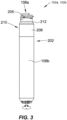
- FIG. 3 shows an example form factor of the LPs 102a, 102b.
- Each LP can include a hermetic housing 202 (e.g., 110 in FIG. 2 ) with electrodes 108a and 108b disposed thereon.
- electrode 108a can be separated from but surrounded partially by a fixation mechanism 205, and the electrode 108b can be disposed on the housing 202.
- the fixation mechanism 205 can be a fixation helix, a plurality of hooks, barbs, or other attaching features configured to attach the pacemaker to tissue, such as heart tissue.
- an antenna e.g., 118
- the electrodes 108a and 108b are examples of the electrodes 108 shown in and discussed above with reference to FIG. 2 .
- the housing can also include an electronics compartment 210 within the housing that contains the electronic components necessary for operation of the pacemaker, including, e.g., a pulse generator, transceiver, a battery, and a processor for operation.
- the hermetic housing 202 can be adapted to be implanted on or in a human heart, and can be cylindrically shaped, rectangular, spherical, or any other appropriate shapes, for example.
- the housing can comprise a conductive, biocompatible, inert, and anodically safe material such as titanium, 316L stainless steel, or other similar materials.
- the housing can further comprise an insulator disposed on the conductive material to separate electrodes 108a and 108b.
- the insulator can be an insulative coating on a portion of the housing between the electrodes, and can comprise materials such as silicone, polyurethane, parylene, or another biocompatible electrical insulator commonly used for implantable medical devices.
- a single insulator 208 is disposed along the portion of the housing between electrodes 108a and 108b.
- the housing itself can comprise an insulator instead of a conductor, such as an alumina ceramic or other similar materials, and the electrodes can be disposed upon the housing.
- the pacemaker can further include a header assembly 212 to isolate 108a and 108b.
- the header assembly 212 can be made from PEEK, tecothane or another biocompatible plastic, and can contain a ceramic to metal feedthrough, a glass to metal feedthrough, or other appropriate feedthrough insulator as known in the art.
- the electrodes 108a and 108b can comprise pace/sense electrodes, or return electrodes.
- a low-polarization coating can be applied to the electrodes, such as sintered platinum, platinum-iridium, iridium, iridium-oxide, titanium-nitride, carbon, or other materials commonly used to reduce polarization effects, for example.
- electrode 108a can be a pace/sense electrode and electrode 108b can be a return electrode.
- the electrode 108b can be a portion of the conductive housing 202 that does not include an insulator 208.
- a helical fixation mechanism 205 can enable insertion of the device endocardially or epicardially through a guiding catheter.
- a torqueable catheter can be used to rotate the housing and force the fixation device into heart tissue, thus affixing the fixation device (and also the electrode 108a in FIG. 2 ) into contact with stimulable tissue.
- Electrode 108b can serve as an indifferent electrode for sensing and pacing.
- the fixation mechanism may be coated partially or in full for electrical insulation, and a steroid-eluting matrix may be included on or near the device to minimize fibrotic reaction, as is known in conventional pacing electrode-leads.
- LPs 102a and 102b can utilize implant-to-implant (i2i) communication through event messages to coordinate operation with one another in various manners.
- i2i communication, i2i event messages, and i2i event markers are used interchangeably herein to refer to event related messages and IMD/IMD operation related messages transmitted from an implanted device and directed to another implanted device (although external devices, e.g., a programmer, may also receive i2i event messages).
- LP 102a and LP 102b operate as two independent leadless pacers maintaining beat-to-beat dual-chamber functionality via a "Master/Slave" operational configuration.
- the ventricular LP 102b shall often be referred to as "vLP” and the atrial LP 102a shall often be referred to as "aLP".
- the LP 102 that is designated as the master device may implement all or most dual-chamber diagnostic and therapy determination algorithms.
- the master device may implement all or most dual-chamber diagnostic and therapy determination algorithms.
- the vLP is a "master” device, while the aLP is a "slave” device.
- the aLP may be designated as the master device, while the vLP may be designated as the slave device.
- the master device orchestrates most or all decision-making and timing determinations (including, for example, rate-response changes).
- FIG. 4 is a timing diagram 400 demonstrating one example of an i2i conductive communication for a paced event.
- the i2i conductive communication may be transmitted, for example, from LP 102a to LP 102b.
- an i2i transmission 402 is sent prior to delivery of a pace pulse 404 by the transmitting LP (e.g., LP 102a).
- the transmitting LP e.g., LP 102a
- the i2i transmission 402 includes an envelope 406 that may include one or more individual pulses.
- envelope 406 includes a low frequency pulse 408 followed by a high frequency pulse train 410.
- Low frequency pulse 408 lasts for a period Ti 2iLF
- high frequency pulse train 410 lasts for a period Ti 2iHF .
- the end of the low frequency pulse 408 and the beginning of the high frequency pulse train 410 are separated by a gap period, T i2iGap .
- the envelope 406 can be transmitted during a refractory period that follows the delivery of the pacing pulse.
- the i2i transmission 402 lasts for a period Ti2iP, and pace pulse 404 lasts for a period Tpace.
- the end of i2i transmission 402 and the beginning of pace pulse 404 are separated by a delay period, TdelayP.
- the delay period may be, for example, between approximately 0.0 and 10.0 milliseconds (ms), particularly between approximately 0.1 ms and 2.0 ms, and more particularly approximately 1.0 ms.
- ms milliseconds
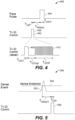
- FIG. 5 is a timing diagram 500 demonstrating one example of an i2i communication for a sensed event.
- the i2i communication may be transmitted, for example, from LP 102a to LP 102b.
- the transmitting LP e.g., LP 102a detects the sensed event when a sensed intrinsic activation 502 crosses a sense threshold 504.
- a predetermined delay period, T delayS after the detection, the transmitting LP transmits an i2i transmission 506 that lasts a predetermined period T i2iS .
- the delay period may be, for example, between approximately 0.0 and 10.0 milliseconds (ms), particularly between approximately 0.1 ms and 2.0 ms, and more particularly approximately 1.0 ms.
- i2i transmission 506 may include an envelope that may include one or more individual pulses.
- the envelope of i2i transmission 506 may include a low frequency pulse followed by a high frequency pulse train.
- the i2i transmission 506 is transmitted during a refractory period that follows the sensed event.
- the first LP produces an AS/AP event marker to indicate that an atrial sensed (AS) event or atrial paced (AP) event has occurred or will occur in the immediate future.
- AS atrial sensed
- AP atrial paced
- the AS and AP event markers may be transmitted following the corresponding AS or AP event.
- the first LP may transmit the AP event marker slightly prior to delivering an atrial pacing pulse.
- the second LP initiates an atrioventricular (AV) interval after receiving an AS or AP event marker from the first LP; and initiates a post atrial ventricular blanking (PAVB) interval after receiving an AP event marker from the first LP.
- AV atrioventricular
- PAVB post atrial ventricular blanking
- the first and second LPs may operate in a "pure" master/slave relation, where the master LP delivers "command" markers in addition to or in place of "event” markers.
- a command marker directs the slave LP to perform an action such as to deliver a pacing pulse and the like.
- the slave LP delivers an immediate pacing pulse to the atrium when receiving an AP command marker from the master LP.
- communication and synchronization between the aLP and vLP is implemented via conducted communication of markers/commands in the event messages (per i2i communication protocol).
- conducted communication represents event messages transmitted from the sensing/pacing electrodes at frequencies outside the RF (e.g., Wi-Fi or BLE) frequency range.
- the event messages may be conveyed over communication channels operating in the RF frequency range.
- the figures and corresponding description below illustrate non-limiting examples of markers that may be transmitted in event messages.
- the figures and corresponding description below also include the description of the markers and examples of results that occur in the LP that receives the event message.
- Table 1 represents example event markers sent from the aLP to the vLP
- Table 2 represents example event markers sent from the vLP to the aLP.
- AS event markers are sent from the aLP each time that an atrial event is sensed outside of the post ventricular atrial blanking (PVAB) interval or some other alternatively-defined atrial blanking period.
- the AP event markers are sent from the aLP each time that the aLP delivers a pacing pulse in the atrium.
- the aLP may restrict transmission of AS markers, whereby the aLP transmits AS event markers when atrial events are sensed both outside of the PVAB interval and outside the post ventricular atrial refractory period (PVARP) or some other alternatively-defined atrial refractory period.
- the aLP may not restrict transmission of AS event markers based on the PVARP, but instead transmit the AS event marker every time an atrial event is sensed.
- an aLP when an aLP transmits an event message that includes an AS event marker (indicating that the aLP sensed an intrinsic atrial event), the vLP initiates an AV interval timer. If the aLP transmits an AS event marker for all sensed events, then the vLP would preferably first determine that a PVAB or PVARP interval is not active before initiating an AV interval timer. If however the aLP transmits an AS event marker only when an intrinsic signal is sensed outside of a PVAB or PVARP interval, then the vLP could initiate the AV interval timer upon receiving an AS event marker without first checking the PVAB or PVARP status.
- the vLP When the aLP transmits an AP event marker (indicating that the aLP delivered or is about to deliver a pace pulse to the atrium), the vLP initiates a PVAB timer and an AV interval time, provided that a PVARP interval is not active.
- the vLP may also blank its sense amplifiers to prevent possible crosstalk sensing of the remote pace pulse delivered by the aLP.
- V2A Markers / Commands (i.e., from vLP to aLP) Marker Description Result in aLP VS Notification of a sensed event in ventricle • Initiate PVARP VP Notification of a paced event in ventricle • Initiate PVAB • Initiate PVARP AP Command to deliver immediate pace pulse in atrium • Deliver immediate pace pulse to atrium
- the vLP when the vLP senses a ventricular event, the vLP transmits an event message including a VS event marker, in response to which the aLP may initiate a PVARP interval timer.
- the vLP delivers or is about to deliver a pace pulse in the ventricle, the vLP transmits VP event marker.
- the aLP receives the VP event marker, the aLP initiates the PVAB interval timer and also the PVARP interval timer.
- the aLP may also blank its sense amplifiers to prevent possible crosstalk sensing of the remote pace pulse delivered by the vLP.
- the vLP may also transmit an event message containing an AP command marker to command the aLP to deliver an immediate pacing pulse in the atrium upon receipt of the command without delay.
- the foregoing event markers are examples of a subset of markers that may be used to enable the aLP and vLP to maintain full dual chamber functionality.
- the vLP may perform all dual-chamber algorithms, while the aLP may perform atrial-based hardware-related functions, such as PVAB, implemented locally within the aLP.
- the aLP is effectively treated as a remote 'wireless' atrial pace/sense electrode.
- the vLP may perform most but not all dual-chamber algorithms, while the aLP may perform a subset of diagnostic and therapeutic algorithms.
- vLP and aLP may equally perform diagnostic and therapeutic algorithms.
- decision responsibilities may be partitioned separately to one of the aLP or vLP. In other embodiments, decision responsibilities may involve joint inputs and responsibilities.
- i2i messages Messages that are transmitted between LPs (e.g., the aLP and the vLP) can be referred to herein generally as i2i messages, since they are implant-to-implant messages.
- messages can include event markers that enable one LP to inform the other LP of a paced event or a sensed event. For example, in certain embodiments, whenever the aLP 102a senses an atrial event or paces the right atrium, the aLP will transmit an i2i message to the vLP 102b to inform the vLP of the sensed or paced event in the atrium.
- the vLP 102b may start one or more timers that enable the vLP to sense or pace in the right ventricle. Similarly, the vLP may transmit an i2i message to the aLP 102a whenever the vLP senses a ventricular event or paces the right ventricle.
- the i2i messages that are sent between LPs may be relatively short messages that simply allow a first LP to inform a second LP of an event that was sensed by the first LP or caused (paced) by the first LP, and vice versa.
- Such i2i messages can be referred to herein as event marker i2i messages, or more succinctly as event i2i messages.
- the i2i messages that are sent between LPs in certain instances, can be extended i2i messages that include (in addition to an event marker) an extension.
- an extended i2i message includes an event marker (e.g., 9 bits), followed by an extension indicator (e.g., 2 bits), followed by an extended message payload portion (e.g., 17 bits), followed by a cyclic redundancy check (CRC) code (e.g., 6 bits) or some other type of error detection and correction code.
- an event marker e.g., 9 bits
- an extension indicator e.g., 2 bits
- an extended message payload portion e.g., 17 bits
- CRC cyclic redundancy check
- the i2i message will include an extension indicator so that the receiving LP knows whether or not the i2i message it receives includes an extension portion. In such embodiments, even a relatively short event i2i message will include an extension indicator.
- the extension indicator e.g., 2 bits
- the extension indicator is used by the LP (or other IMD) sending the i2i message to indicate, to the LP receiving the i2i message, whether or not the i2i message is an extended i2i message.
- the LP receiving an i2i message determines based on the extension indicator bits that the received i2i message is not an extended i2i message, then the LP receiving the i2i message can ignore any bits that follow the extension bits. In such a case, the LP receiving the i2i message only decodes the event marker.
- the LP receiving an i2i message determines based on the extension indicator bits that the received i2i message is an extended i2i message, then the LP receiving the i2i message will also decode the bits that follow the extension bits, and determine based on a CRC code (or other type of error detection and correction code), whether the i2i message is a valid message.
- event i2i messages that are not extended i2i messages do not include any error detection and correction code.
- the event marker bits and the extension indicator bits are located, respectively, in an event marker field and an extension indicator field of an i2i message packet.
- the extended portion (that follows the event marker bits and the extension indicator bits) includes message bits (in a message field) and rate indicator bits (in a rate indicator field), which are parts of the payload.
- the payload can alternatively, or additionally, include other types of fields, such as an acknowledgement field that is used in certain situations for one LP to acknowledge reception of an i2i message from another LP of certain (e.g., critical) types of message.
- the payload can include a pacing rate indicator that enables one LP to inform another LP of a pacing rate.
- a pacing rate indicator that enables one LP to inform another LP of a pacing rate.
- an LP system provides rate responsive pacing, wherein a pacing rate is adjusted in dependence on a patient's physical activity as detected, e.g., using an accelerometer, temperature sensor, and/or other type of sensor of an LP.
- the vLP may inform the aLP of the rate at which the patient's heart should be paced so that the aLP and vLP can perform synchronized pacing.
- the vLP can send a pacing rate indicator to the aLP in the payload of an extended i2i message.
- the pacing rate indicator can, e.g., be a value indicating a pacing rate value (e.g., 80 bpm), a code that the aLP that can look up (e.g., in a stored look up table) and corresponds to a pacing rate value, or a value that the aLP feeds into an equation to determine the pacing rate, but is not limited thereto.
- the pacing rate indicator can be beat-to-beat interval value (e.g., 0.75 seconds), a code that the aLP can look up and corresponds to a beat-to-beat interval value, or a value that the aLP feeds into an equation to determine the beat-to-beat interval, but is not limited thereto.
- beat-to-beat interval value e.g. 0.75 seconds
- code that the aLP can look up and corresponds to a beat-to-beat interval value e.g. 0.75 seconds
- a code that the aLP can look up and corresponds to a beat-to-beat interval value
- a value that the aLP feeds into an equation to determine the beat-to-beat interval e.g. 0.75 seconds
- i2i communication is critical for proper synchronization of the system.
- i2i communication is performed using conductive communication
- i2i communication is unreliable or simply fails, which adversely affects the ability of the system to perform synchronous pacing.
- the gradient noise produced by the MRI system will prevent the LPs from successfully communicating with one another using conductive communication.
- a dual chamber LP system should be switched from a dual chamber pacing mode (e.g., DOO mode pacing) to a single chamber pacing mode (e.g., VOO mode pacing) prior to an MRI scan using an external programmer (e.g., 109).
- a dual chamber pacing mode e.g., DOO mode pacing
- a single chamber pacing mode e.g., VOO mode pacing
- the LPs 102 can use a sensor to detect when they are being subjected to an MRI scan, and in response thereto the LPs 102 can autonomously switch themselves to a single chamber pacing mode (e.g., VOO mode pacing). Thereafter, when the LPs 102 no longer detect that they are being subjected to an MRI scan, the LPs 102 can autonomously switch themselves back to the dual chamber pacing mode.
- the single chamber pacing mode e.g., VOO mode pacing
- the patient may not receive the appropriate level of care that the patient needs, which is undesirable.
- IMDs can communicate with one another using RF communication even when the IMDs are subjected to an MRI scan.
- a detriment of IMDs only utilizing RF communication to communicate with one another is that RF communication is much less power efficient than conductive communication, rendering the lifespan of such IMDs relatively short of the IMD only used RF communication to communicate with another IMD, which is undesirable.
- IMDs e.g., such as two LPs of a dual chamber LP system
- IMDs are configured to communicate with one another primarily and by default using conductive communication, which is energy efficient
- the IMDs are configured to use RF communication (which is less energy efficient) as a backup up and/or auxiliary type of communication.
- the lifespan of the IMDs can be relatively long, potentially up to seven years or more, which is desirable.
- the IMDs should be capable of performing both conductive communication and RF communication.
- the LPs 102 described above with reference to FIGS.
- IMDs 1-5 are examples of IMDs that are capable of performing both conductive communication and RF communication, because they include by a conducive communication transceiver and an RF communication transceiver.
- embodiments of the present technology are not just limited to use with the LPs 102 described herein, as would be appreciated by one of ordinary skill in the art reading this document.
- IMDs e.g., LPs 102 are configured to normally communicate with one another using conductive communication (and more specifically, by sending conductive communication messages to one another), while an MRI mode of the IMD is deactivated (aka turned off), and the IMDs are configured to communicate with one another using RF communication (and more specifically, by sending RF communication messages to one another) when the MRI mode of the IMD is activated (aka turned on).
- conductive communication and more specifically, by sending conductive communication messages to one another
- RF communication and more specifically, by sending RF communication messages to one another
- the IMDs will normally communicate using energy efficient conductive communication, and the IMDs will still be able to communicate with one another (albeit less energy efficiently) using RF communication when the IMDs are subjected to an MRI scan.
- the MRI mode of the IMDs can be selectively activated (i.e., turned on) using a non-implanted device, such as, but not limited to, an external programmer (e.g., 109) that wirelessly communicates with the IMD.
- a non-implanted device such as, but not limited to, an external programmer (e.g., 109) that wirelessly communicates with the IMD.
- the MRI mode of the IMDs can be deactivated (e.g., after an MRI scan is completed) by the same non-implanted device, or another non-implanted device. It would also be possible for the MRI mode to be deactivated (i.e., turned off) after a specified amount of time has elapsed since the MRI mode was turned on.
- a controller 112 and/or timer of an IMD can be used to determine whether an MRI timeout period (e.g., 6 hours) has expired, and the IMD can be autonomously deactivate (i.e., turn off) that MRI mode once the MRI timeout period expires.
- an MRI timeout period e.g. 6 hours
- the IMD can be autonomously deactivate (i.e., turn off) that MRI mode once the MRI timeout period expires.
- the MRI mode of an IMD can cause the IMD to send messages using RF communication instead or, or in addition to, sending messages using conductive communication.
- the IMD can transmit just RF communication messages to another IMD, or the IMD can transmit both RF communication messages and conductive communication messages.
- the RF communication transceiver e.g., 134) of an IMD (e.g., LP 102) is disabled when the MRI mode is deactivated, and the RF communication transceiver is enabled when the MRI mode is activated.
- the conductive communication transceiver is disabled when the RF communication transceiver (e.g., 134) is enabled.
- the receiver(s) (e.g., 120, 124) of the conductive communication transceiver can be disabled while the RF communication transceiver is enabled.
- the conductive communication transceiver (e.g., 124) remains enabled while the RF communication transceiver (e.g., 134) is enabled, so that a controller (e.g., 112) of the IMD can determine when a conductive communication capability has been restored, in response to which, the RF communication transceiver (e.g., 134) can be disabled.
- an IMD e.g., LP 102
- the components and/or capabilities of an IMD that are selectively enabled and disabled, based on whether or not the IMD is in its MRI mode only involve communication components and capabilities of the IMD. More specifically, in certain embodiments conductive communication capabilities are enabled and RF communication capabilities are disabled when the MRI mode is turned off, and RF communication capabilities are enabled when the MRI mode is turned on. In certain such embodiments, when the MRI mode is turned on, the conductive communication capabilities are disabled. In other embodiments, when the MRI mode is turned on, the conductive communication capabilities remain enabled, such that when the MRI mode it turned on, both the RF communication and the conductive communication capabilities of the IMD are enabled.
- the IMDs can themselves detect when the IMDs are likely being exposed to an MRI scan, and the IMDs themselves can selectively activate their MRI mode. More specifically, a sensor of an IMD can detect a magnetic field, or a surrogate thereof, that is likely generated by an MRI system, and in response thereto, the IMD (or more specifically, the controller thereof) can activate the MRI mode of the IMD. For example, referring back to FIG.
- the magnetic field sensor 156 can be used to detect when the LP 102 is being exposed to a magnetic field that is likely generated by an MRI system.
- a sensor can be, e.g., a Hall effect sensor, a GMR sensor, or a reed switch, but is not limited thereto, as explained above.
- a magnetic field sensor e.g., 156
- another type of sensor can be used to detect a surrogate of a magnetic field that is produced by an MRI system, which in response to be detected, causes an MRI mode of the LP 102 to be activated.
- Such a surrogate of a magnetic field that is produced by an MRI system can be a secondary acoustic and/or vibratory effect of an MRI system.
- the accelerometer 154 or some other sensor configured to detect acceleration, sound and/or vibration
- the accelerometer 154 can detect secondary acoustic and/or vibratory effects of an MRI system, as was described above, which in response to be detected, can cause an MRI mode of the LP 102 to be activated.
- the first and second IMDs can be the LPs 102a and 102b, respectively.
- the first and second IMDs can be the LPs 102b and 102a, respectively.
- the first IMD can be one of the LPs 102a or 102b, and the second IMD can be the S-ICD 106.
- the first IMD can be the S-ICD 106
- the second IMD can be one of the LPs 102a or 102b. It would also be possible that one of the first and second IMDs is an insertable cardiac monitor (ICM).
- ICM insertable cardiac monitor
- One of the first and second IMDs can be a non-vascular implantable cardioverter-defibrillator (NV-ICD), e.g., 106, which may or may not be an S-ICD.
- NV-ICD non-vascular implantable cardioverter-defibrillator
- the first trigger event comprises a magnetic resonance imaging (MRI) mode of the first IMD being activated
- the second trigger event comprises the MRI mode of the first IMD being deactivated.
- the MRI mode of the first IMD is activated using a non-implanted device (e.g., an external programmer), and the MRI mode of the first IMD is deactivated using a non-implanted device that can be the same as or different than the non-implanted device that activated the MRI mode. It is also possible for the MRI mode to be deactivated in response to an MRI timeout period expiring.
- the MRI mode of the first IMD is activated in response to a sensor of the first IMD detecting a magnetic field, or a surrogate thereof, that is likely generated by an MRI system.
- the MRI mode of the first IMD is deactivated in response to the sensor of the first IMD no longer detecting the magnetic field, or the surrogate thereof, that is likely generated by an MRI system. It is also possible for the MRI mode to be deactivated in response to an MRI timeout period expiring.
- the first trigger event comprises the first IMD determining that the second IMD did not successfully receive one or more of the messages, intended for the second IMD, that the first IMD transmitted using conductive communication.
- the first IMD also uses conductive communication to transmit one or more messages intended for the second IMD during the second period of time, as noted above.
- the second trigger event comprises the first IMD determining that the second IMD successfully received at least one of the one or more messages, intended for the second IMD, that were transmitted by the first IMD using conductive communication during the second period of time.
- first IMD continues to transmit messages(s) using conductive communication during the second period of time that enables the first IMD to determine when the use of conductive communication is again successful, thereby enabling the first IMD to disable the less energy efficient RF communication once successful conductive communication is restored.
- the first trigger event comprises a level of noise detected by the first IMD exceeding a first noise threshold
- the second trigger event comprises the level of noise detected by the first IMD being below a second noise threshold, which can be the same as or different than the first noise threshold.
- the first trigger event comprises at least one of an arrhythmia being detected or arrhythmia therapy being delivered
- the second trigger event comprises at least one of the arrhythmia no longer being detected or the arrhythmia therapy being completed.
- one of the first IMD and the second IMD comprises a leadless pacemaker (LP), and the other one of the first IMD and the second IMD comprises another LP, a non-vascular implantable cardioverter-defibrillator (NV-ICD), or an insertable cardiac monitor (ICM).
- LP leadless pacemaker
- NV-ICD non-vascular implantable cardioverter-defibrillator
- ICM insertable cardiac monitor
- FIG. 6A is a high level flow diagram that is used to summarize methods for improving communication between first and second IMDs, wherein such IMDs are remotely located relative to one another and are capable of communicating with one another using both conductive communication and RF communication, according to certain embodiments of the present technology.
- the steps shown in FIG. 6A are from the perspective of the first IMD, and are performed by the first IMD.
- the second IMD can independently perform the same or similar steps, in which case from the perspective of the second IMD the terms first and second can be swapped in FIG. 6A (and similarly, in FIG. 6B ).
- step 602 involves the first IMD using conductive communication to transmit one or more messages intended for the second IMD, without using RF communication to transmit any messages intended for the second IMD.
- the first IMD can be configured to normally and/or by default use conductive communication as its primary and preferred mode of communication, because conductive communication is significantly more energy efficient than RF communication.
- the messages that are sent from the first IMD to the second IMD can be an i2i message that informs the second IMD of an intrinsic or paced cardiac event that occurred in a first cardiac chamber (in or on which the first IMD is implanted), so that the second IMD can appropriate time its pacing of a second cardiac chamber (in or on which the second IMD is implanted). More generally, such messages can be event messages, but are not limited thereto.
- the messages that are sent by the aLP 102a to the vLP 102b using conductive communication can be or include an atrial sensed (AS) event marker, or an atrial paced (AP) event marker, or can include some other type of message, such as a command message, or an acknowledgement (ACK) message that the aLP 102a uses to acknowledge that it received a message from the vLP 102b.
- AS atrial sensed
- AP atrial paced
- ACK acknowledgement
- the messages that are sent by the vLP 102b to the aLP 102a can be or include a ventricular sensed (VS) event marker, or a ventricular paced (VP) event marker, or can include some other type of message, such as a command message, or an acknowledgement (ACK) message that the vLP 102b uses to acknowledge that it received a message from the aLP 102a.
- VS ventricular sensed
- VP ventricular paced
- ACK acknowledgement
- these are just a few examples of the types of messages that can be sent from a first IMD to a second IMD, and vice versa, which are not intended to be all encompassing. Indeed, as explained above, one or both the IMDs need not be an LP. However, for the remainder of this discussion, it is often assumed that the first and second IMDs are LPs.
- step 604 involves monitoring for a first trigger event
- step 606 involves determining whether the first trigger event was detected. While steps 604 and 606 are shown as separate steps in FIG. 6A , it would also be possible that steps 604 and 606 be combined into a single step.
- the first trigger event that is monitored for at steps 604 and 606, as will be appreciated from the discussion below, is some type of event that would adversely affect the efficacy of conductive communication, such that the first IMD should start using RF communication (at least temporarily) instead of (or in addition to) using conductive communication to send message(s) to the second IMD, even though RF communication is less energy efficient than conductive communication.
- step 606 If the answer to the determination at step 606 is No (i.e., if the first trigger event is not detected), then flow returns to step 602 and the first IMD continues to use conductive communication (without using RF communication) to transmit message(s) to the second IMD. In other words, steps 602, 604, and 606 will continue in a loop until the answer to the determination at step 606 is Yes.
- the period of time during which the first IMD transmits messages to the second IMD using conductive communication, without using RF communication can be referred to herein as a first period of time.
- step 606 If the answer to the determination at step 606 is Yes (i.e., if the first trigger event is detected), then flow goes to step 608a and the first IMD starts using RF communication (without using conductive communication) to transmit message(s) to the second IMD.
- step 610 involves monitoring for a second trigger event
- step 612 involves determining whether the second trigger event was detected. While steps 610 and 612 are shown as separate steps in FIG. 6A , it would also be possible that steps 610 and 612 be combined into a single step.
- the second trigger event that is monitored for at steps 610 and 612 is some type of event that would favorably affect the efficacy of conductive communication, such that the first IMD should return to using conductive communication instead of using RF communication to send message(s) to the second IMD, because conductive communication is more energy efficient than RF communication.
- step 612 If the answer to the determination at step 612 is No (i.e., if the second trigger event is not detected), then flow returns to step 608a and the first IMD continues to use RF communication (without using conductive communication) to transmit message(s) to the second IMD. In other words, steps 608a, 610, and 612 will continue in a loop until the answer to the determination at step 612 is Yes.
- the period of time during which the first IMD transmits messages to the second IMD using RF communication can be referred to herein as a second period of time.
- step 612 If the answer to the determination at step 612 is Yes (i.e., if the second trigger event is detected), then flow goes to back to step 602 and the first IMD starts using conductive communication (without using RF communication) to transmit message(s) to the second IMD.
- the messages that the first IMD transmits to the second IMD at instances of steps 602 and 604 can also be referred to as messages intended for the second IMD, since the second IMD is the intended recipient of the messages, but there is no guarantee that the messages will actually be received by the second IMD.
- the one or more messages intended for the second IMD, that are transmitted by the first IMD using conductive communication at one or more instances of step 602 during the first period of time are transmitted within a first frequency range.
- the one or more messages intended for the second IMD, that are transmitted by the first IMD using RF communication during the second period of time are transmitted within a second frequency range that is above the first frequency range.
- the frequency range that is used for performing conductive communication at instances of step 602 can be, e.g., within the range of about 1 KHz to about 250 KHz.
- the frequency range that is used for RF communication at instances of step 608a is significantly higher, depending upon which type of RF communication is used. For example, if Bluetooth Low Energy (BLE) is used for RF communication at instance of step 608a, then the frequency range is within the range of about 2.40 GHz to about 2.48 GHz.
- BLE Bluetooth Low Energy
- MedRadio Medical Device Radiocommunications Service
- the frequency range is within the range of about 400 MHz to about 406 MHz. It would also be possible to use one of the WiFi frequency bands for RF communication.
- the first trigger event that is monitored for (at steps 604 and/or 606) comprises a magnetic resonance imaging (MRI) mode of the first IMD being activated
- the second trigger event that is monitored for (at steps 610 and/or 612) comprises the MRI mode of the first IMD being deactivated.
- the first IMD can communication with the second IMD using RF communication during a period of time (e.g., the second period of time) that a patient (in which the first and second IMDs are implanted) is being scanned using an MRI system, thereby enabling the first and second IMDs to continuously synchronously pace the patient even when the MRI system prevents the use of conductive communication.
- the MRI mode of the first IMD can be manually or automatically activated and deactivated, depending upon the embodiment and implementation.
- the MRI mode of the first IMD is activated using an external programmer (e.g., 109), or some other types of non-implanted device.
- the MRI mode of the first IMD can be deactivated using an external programmer that can be the same as or different than the external programmer that activated the MRI mode.
- a clinician can use an external programmer (e.g., 109) to activate the MRI mode of the IMDs. Then, after the MRI scan has been completed, the clinician can use the external programmer (e.g., 109) to deactivate the MRI mode. It would also be possible for the MRI mode to be deactivated in response to an MRI timeout period expiring.
- an external programmer e.g. 109
- the clinician can use the external programmer (e.g., 109) to deactivate the MRI mode. It would also be possible for the MRI mode to be deactivated in response to an MRI timeout period expiring.
- an amount of time since the MRI mode was initially activated can be monitored using a timer, or a controller (e.g., 112), to determine whether an MRI timeout period has elapsed.
- the MRI timeout period can, for example, be in the range of 1 hour to 10 hours, and in a specific example can be 6 hours.
- the MRI timeout period can be pre-programmed to a default value (e.g., 6 hours), but may be reprogrammed by a clinician.
- a benefit of having the IMD automatically deactivate the MRI mode, after the MRI time out period expires, is that the IMD will soon transition back to using conductive communication to send messages to the second IMD, even if a clinician forgets to deactivate the MRI mode after the MRI scan has been completed.
- the MRI mode of the first IMD is automatically activated in response to a sensor of the first IMD detecting a magnetic field, or a surrogate thereof, that is likely generated by an MRI system.
- a magnetic field sensor e.g., 156 in FIG. 2
- a controller e.g., 112 of the first IMD can automatically activate the MRI mode of the first IMD.
- such a magnetic field sensor can be, e.g., a Hall effect sensor, a GMR sensor, or a reed switch, but is not limited thereto.
- the MRI mode of the first IMD can then be automatically deactivated in response to the magnetic field sensor (e.g., 156) no longer detecting a magnetic field that is likely generated by an MRI system. It would also be possible for the MRI mode to be deactivated in response to an MRI timeout period expiring. Example details of how the MRI mode may be deactivated in response to an MRI timeout period expiring were described above, and thus, need not be repeated.
- a magnetic field sensor e.g., 156
- another type of sensor can be used to detect a surrogate of a magnetic field that is likely produced by an MRI system, which in response to be detected, causes an MRI mode of the IMD to be activated.
- a surrogate of a magnetic field that is produced by an MRI system can be a secondary acoustic and/or vibratory effect of an MRI system.
- the accelerometer e.g., 154 in FIG.
- the MRI mode can then be automatically deactivated in response to the same sensor (e.g., the accelerometer 154) no longer detecting the surrogate of the magnetic field from an MRI system. It would also be possible for the MRI mode to be deactivated in response to an MRI timeout period expiring.
- the first trigger event that is monitored for at step 604 and/or 606 comprises the first IMD determining that the second IMD did not successfully receive one or more of the messages, intended for the second IMD, that the first IMD transmitted using conductive communication.
- the first IMD can determine that the second IMD did not successfully receive one or more of the messages, intended for the second IMD, that the first IMD transmitted using conductive communication.
- the first IMD can make this determination based on the first IMD not receiving an expected acknowledgement (ACK) message from the second IMD.
- ACK expected acknowledgement
- the first IMD can make this determination based on the first IMD receiving a message from second IMD that informs the first IMD that the second IMD failed to receive a message that the second IMD expected to receive from the first IMD.
- This can involve, for example, the second IMD sending to the first IMD a message that includes an indicator (e.g., an error code) in its payload, or header, that indicates to the first IMD that the second IMD failed to receive an expected message from the first IMD.
- an indicator e.g., an error code
- the vLP 102b may expect to receive an AS or an AP event type of conductive communication message once every cardia cycle from aLP 102a, and if the vLP 102b does not receive such a message, the vLP 102b can send an error code (or other type of indicator) to the aLP 102a, which informs the aLP 102a that the vLP 102b failed to receive an expected AS or AP event message from the aLP 102a.
- an error code or other type of indicator
- the aLP 102a may expect to receive a VS or an VP event type of conductive communication message once every cardia cycle from vLP 102b, and if the aLP 102a does not receive such a message, the aLP 102a can send an error code (or other type of indicator) to the vLP 102b, which informs the vLP 102b that the aLP 102a failed to receive an expected VS or VP event message from the vLP 102b.
- the second trigger event that is monitored for at instances of steps 610 and/or 612 can be a specified amount of time elapsing since the first IMD transitioned to using RF communication (instead of conductive communication) in response to the first trigger event being detected at an instance of step 604 and/or 606.
- RF communication instead of conductive communication
- Gradient noise from an MRI system is just one example of a type of noise that may adversely affect conductive communication, without adversely affecting RF communication.
- the first trigger event that is monitored for at instances of steps 604 and/or 606 can more generally be a level of noise (e.g., within the frequency range that is used for performing conductive communication) exceeding a first noise threshold
- the second trigger event that is monitored for at instances of steps 610 and/or 612 can be the level of noise being below a second noise threshold, which can be the same as or different than the first noise threshold.
- Examples of such other types of noise include, but are not limited to, electromagnetic interference (EMI), or noise from an Electronic Article Surveillance (EAS) gate, a power transformer, a wireless charging device, and/or the like.
- EMI electromagnetic interference
- EAS Electronic Article Surveillance
- the first trigger event that is monitored for at instances of steps 604 and/or 606 can be an arrhythmia being detected or arrhythmia therapy being delivered
- the second trigger event that is monitored for at instances of steps 610 and/or 612 can be the arrhythmia no longer being detected or the arrhythmia therapy being completed.
- an LP detects ventricular fibrillation (VF)
- the LP can turn on its RF communication capability to more quickly and reliably communication with an NV-ICD to instruct the ICD to deliver a defibrillation shock.
- VF ventricular fibrillation
- the first trigger event can be the detection of any type of arrhythmia or arrhythmia therapy, or just specific types of arrhythmias or arrhythmia therapies.
- one or more messages is/are transmitted by the first IMD using RF communication, without using conductive communication.
- a potential downside of such embodiments is that the first IMD may not timely identify a point in time when the first IMD can successfully return to transmitting messages (intended for the second IMD) using more energy efficient conductive communication, without using the less energy efficient RF communication.
- the first IMD transitions to sending messages using both conductive communication and RF communication.
- Such alternative embodiments are summarized below with reference to the high level flow diagram of FIG. 6B .
- step 608b is performed in place of the step 608a of FIG. 6A .
- the first IMD uses both RF communication and conductive communication to transmit one or more messages that are intended for the second IMD.
- the first trigger event can be the first IMD determining that the second IMD did not successfully receive one or more of the messages, intended for the second IMD, that the first IMD transmitted using conductive communication.
- the second trigger event can be the first IMD determining that the second IMD successfully received one or more of the messages, intended for the second IMD, that the first IMD transmitted using conductive communication, thereby enabling the first IMD to stop (at least temporarily) using the less energy efficient RF communication to transmit messages to the second IMD.
- Example details of how such an embodiment may be implemented are described below with reference to FIG. 7 .
- each of the IMDs can separately use such an embodiment to communicate with the other IMD.
- the high level flow diagram of FIG. 7 will now be described. In other words, each one of the plurality of IMDs can separately implement the method summarized with reference to FIG. 7 (or FIG. 6A or 6B ).
- step 702 involves an IMD (e.g., a first IMD) sending and receiving i2i messages from another IMD (e.g., a second IMD) using conductive communication.
- Step 704 involves the IMD determining whether it received an i2i message using conductive communication, from the other IMD, e.g., within a message reception window.
- step 706 there is a determination of whether the received i2i message included a communication error indicator, which indicated that the other IMD (e.g., the second IMD) did not successfully receive a conductive communication message from the IMD (e.g., the first IMD), e.g., within its own message reception window. If the answer to step 706 is No, then flow returns to step 702. Steps 702, 704, and 706 will continue in a loop so long as the conductive communication between the IMDs is successfully performed.
- a communication error indicator which indicated that the other IMD (e.g., the second IMD) did not successfully receive a conductive communication message from the IMD (e.g., the first IMD), e.g., within its own message reception window. If the answer to step 706 is No, then flow returns to step 702. Steps 702, 704, and 706 will continue in a loop so long as the conductive communication between the IMDs is successfully performed.
- step 704 if the answer to the determination at step 704 is No (i.e., if the IMD did not receive an i2i message from the other IMD using conductive communication), then at step 708 an RF communication capability of the IMD is turned on.
- the IMD sends the i2i message to the other IMD using both RF communication and conductive communication, wherein the i2i message includes a communication error indicator that informs the other IMD (e.g., the second IMD) that the IMD (e.g., the first IMD) failed to successfully receive the previous expected i2i message from the other IMD (e.g., the second IMD) using conductive communication.
- the other IMD e.g., the second IMD
- the IMD e.g., the first IMD
- Such an indicator e.g., an error code
- send and transmit are often used interchangeably herein, as are the terms sent and transmitted.
- the IMD monitors for an i2i message from the other IMD using both RF communication and conductive communication.
- step 714 there is a determination of whether the IMD received an i2i message from the other IMD using conductive communication. If the answer to the determination at step 714 is No, then flow returns to step 710.
- the loop that includes steps 710, 712, and 714 will continue until the IMD receives an i2i message from the other IMD using conductive communication. For the sake of this discussion, it is assumed that the IMD is successfully receiving i2i messages from the other IMD using RF communication during a period of time that the loop including 710, 712, and 714 may be repeated.
- an IMD receives an i2i message over a conductive communication channel.
- an i2i message is received using RF communication
- the IMD receives an i2i message over an RF communication channel. Because the frequency range that is used for RF communication is above the frequency range that is used for conductive communication, as explained above, it can be said that the frequency of the RF communication channel is above the frequency of the conducive communication channel.
- step 716 the RF communication capability of the IMD is turned off.
- step 706 there is a determination of whether the received i2i message included a communication error indicator, which indicated that the other IMD (e.g., the second IMD) did not successfully receive a conductive communication message from the IMD (e.g., the first IMD), e.g., within its own message reception window. If the answer to step 706 is No, then flow returns to step 702.
- step 706 if the answer to step 706 is Yes, (i.e., if there is an indicator, e.g., an error code) in the i2i message received from the other IMD using conductive communication (which indicated that the other IMD did not successfully receive an expected i2i message using conductive communication), then flow goes to step 718.
- an indicator e.g., an error code
- the RF communication capability of the IMD is turned on.
- the IMD sends the i2i message to the other IMD using both RF communication and conductive communication, wherein the i2i message does not include a communication error indicator that informs the other IMD (e.g., the second IMD) that the IMD (e.g., the first IMD) failed to successfully receive the previous expected i2i message from the other IMD (e.g., the second IMD) using conductive communication.
- the IMD monitors for an i2i message from the other IMD using both RF communication and conductive communication.
- step 724 there is a determination of whether the IMD received an i2i message from the other IMD using conductive communication. If the answer to the determination at step 724 is No, then flow returns to step 710. If the answer to the determination at step 724 is Yes, then flow goes to step 716.
- step 716 the RF communication capability of the IMD is turned off. After step 716, flow goes to step 706, which was already explained above.
- steps 722 and 724 are identical, respectively, to step 712 and 714, it would also be possible to eliminate steps 722 and 724, and that flow goes directly from step 720 to step 712.
- flow can go directly from step 714 to step 706 (and/or directly from step 724 to step 706), and the RF communication capability can instead be turned off whenever the answer to the determination at step 706 is No.
- the flow diagram can be modified such that step 716 is performed between instances of step 706 and 702, whenever the answer to the determination at step 706 is No (i.e., whenever the i2i message that the IMD receives from the other IMD does not include an indicator specifying that the other IMD failed to receive an expected i2i message using conductive communication).
- step 716 is performed between instances of step 706 and 702
- conductive communication is more energy efficient than RF communication, thereby providing for greater IMD longevity.
- conductive communication will fail (e.g., during an MRI scan), but RF communication can be successfully used.
- certain embodiments of the present technology described herein primarily and by default using conductive communication for sending and receiving i2i messages between IMDs, which is energy efficient, and use RF communication as a backup or auxiliary way for sending and receiving i2i messages when needed.
- a feasibility analysis was performed to determine how much the selective use of RF communication (for sending and receiving i2i messages between IMDs) would affect the longevity of an IMD.
- Results of the feasibility analysis were that the selective use of RF communication would reduce the battery longevity of an IMD (and thus, the longevity of the IMD) by less than two weeks, compared to if only conductive communication was used for sending messages between the IMDs. Accordingly, where the battery longevity of an IMD is expected to be about 7 years (i.e., about 364 weeks), the selective use of RF communication in an IMD that primarily and by default uses conductive communication, would likely reduce the battery longevity from about 364 weeks to about 362 weeks, which is a reduction in longevity of only about 0.5%.
- FIG. 8 shows a block diagram of one embodiment of an IMD (e.g., an LP or ICD) 801 that is implanted into the patient as part of the implantable cardiac system in accordance with certain embodiments herein.
- IMD 801 may be implemented as a full-function biventricular pacemaker, equipped with both atrial and ventricular sensing and pacing circuitry for four chamber sensing and stimulation therapy (including both pacing and shock treatment).
- IMD 801 may provide full-function cardiac resynchronization therapy.
- IMD 801 may be implemented with a reduced set of functions and components. For instance, the IMD may be implemented without ventricular sensing and pacing.
- IMD 801 has a housing 800 to hold the electronic/computing components.
- Housing 800 (which is often referred to as the "can”, “case”, “encasing”, or “case electrode”) may be programmably selected to act as the return electrode for certain stimulus modes.
- Housing 800 may further include a connector (not shown) with a plurality of terminals 802, 804, 806, 808, and 810. The terminals may be connected to electrodes that are located in various locations on housing 800 or elsewhere within and about the heart.
- IMD 801 includes a programmable microcontroller 820 that controls various operations of IMD 801, including cardiac monitoring and stimulation therapy.
- Microcontroller 820 includes a microprocessor (or equivalent control circuitry), RAM and/or ROM memory, logic and timing circuitry, state machine circuitry, and I/O circuitry.
- IMD 801 further includes a first pulse generator 822 that generates stimulation pulses for delivery by one or more electrodes coupled thereto.
- Pulse generator 822 is controlled by microcontroller 820 via control signal 824.
- Pulse generator 822 may be coupled to the select electrode(s) via an electrode configuration switch 826, which includes multiple switches for connecting the desired electrodes to the appropriate I/O circuits, thereby facilitating electrode programmability.
- Switch 826 is controlled by a control signal 828 from microcontroller 820.
- the IMD may include multiple pulse generators, similar to pulse generator 822, where each pulse generator is coupled to one or more electrodes and controlled by microcontroller 820 to deliver select stimulus pulse(s) to the corresponding one or more electrodes.
- Microcontroller 820 is illustrated as including timing control circuitry 832 to control the timing of the stimulation pulses (e.g., pacing rate, atrio-ventricular (AV) delay, atrial interconduction (A-A) delay, or ventricular interconduction (V-V) delay, etc.). Timing control circuitry 832 may also be used for the timing of refractory periods, blanking intervals, noise detection windows, evoked response windows, alert intervals, marker channel timing, and so on. Microcontroller 820 also has an arrhythmia detector 834 for detecting arrhythmia conditions and a morphology detector 836. Although not shown, the microcontroller 820 may further include other dedicated circuitry and/or firmware/software components that assist in monitoring various conditions of the patient's heart and managing pacing therapies.
- the stimulation pulses e.g., pacing rate, atrio-ventricular (AV) delay, atrial interconduction (A-A) delay, or ventricular interconduction (V-V) delay, etc.
- IMD 801 is further equipped with a communication modem (modulator/demodulator) 840 to enable wireless communication with the remote slave pacing unit.
- Modem 840 may include one or more transmitters and two or more receivers as discussed herein in connection with FIG. 2 .
- modem 840 may use low or high frequency modulation.
- modem 840 may transmit i2i messages and other signals through conductive communication between a pair of electrodes and/or using RF communication.
- Modem 840 may be implemented in hardware as part of microcontroller 820, or as software/firmware instructions programmed into and executed by microcontroller 820. Alternatively, modem 840 may reside separately from the microcontroller as a standalone component.
- the modem 840 includes both a conductive communication transceiver and an RF communication transceiver. While not specifically shown in FIG. 8 , such an RF communication transceiver can be coupled to an antenna that enables RF communication signals to be transmitted and received for the purpose of transmitting and receiving messages to and from another IMD.
- IMD 801 includes a sensing circuit 844 selectively coupled to one or more electrodes, that perform sensing operations, through switch 826 to detect the presence of cardiac activity in the right chambers of the heart.
- Sensing circuit 844 may include dedicated sense amplifiers, multiplexed amplifiers, or shared amplifiers. It may further employ one or more low power, precision amplifiers with programmable gain and/or automatic gain control, bandpass filtering, and threshold detection circuit to selectively sense the cardiac signal of interest.
- the automatic gain control enables the unit to sense low amplitude signal characteristics of atrial fibrillation.
- Switch 826 determines the sensing polarity of the cardiac signal by selectively closing the appropriate switches. In this way, the clinician may program the sensing polarity independent of the stimulation polarity.
- sensing circuit 844 The output of sensing circuit 844 is connected to microcontroller 820 which, in turn, triggers or inhibits the pulse generator 822 in response to the presence or absence of cardiac activity. Sensing circuit 844 receives a control signal 846 from microcontroller 820 for purposes of controlling the gain, threshold, polarization charge removal circuitry (not shown), and the timing of any blocking circuitry (not shown) coupled to the inputs of the sensing circuitry.
- the IMD may include multiple sensing circuits, similar to sensing circuit 844, where each sensing circuit is coupled to one or more electrodes and controlled by microcontroller 820 to sense electrical activity detected at the corresponding one or more electrodes.
- Sensing circuit 844 may operate in a unipolar sensing configuration or in a bipolar sensing configuration.
- IMD 801 further includes an analog-to-digital (A/D) data acquisition system (DAS) 850 coupled to one or more electrodes via switch 826 to sample cardiac signals across any pair of desired electrodes.
- A/D analog-to-digital
- Data acquisition system 850 is configured to acquire intracardiac electrogram signals, convert the raw analog data into digital data, and store the digital data for later processing and/or telemetric transmission to an external device 854 (e.g., a programmer, local transceiver, or a diagnostic system analyzer).
- Data acquisition system 850 is controlled by a control signal 856 from the microcontroller 820.
- Microcontroller 820 is coupled to a memory 860 by a suitable data/address bus.
- the programmable operating parameters used by microcontroller 820 are stored in memory 860 and used to customize the operation of IMD 801 to suit the needs of a particular patient.
- Such operating parameters define, for example, pacing pulse amplitude, pulse duration, electrode polarity, rate, sensitivity, automatic features, arrhythmia detection criteria, and the amplitude, waveshape and vector of each shocking pulse to be delivered to the patient's heart within each respective tier of therapy.
- the operating parameters of IMD 801 may be non-invasively programmed into memory 860 through a telemetry circuit 864 in telemetric communication via communication link 866 with external device 854. Telemetry circuit 864 allows intracardiac electrograms and status information relating to the operation of IMD 801 (as contained in microcontroller 820 or memory 860) to be sent to external device 854 through communication link 866.
- IMD 801 can further include magnet detection circuitry (not shown), coupled to microcontroller 820, to detect when a magnet is placed over the unit.
- a magnet may be used by a clinician to perform various test functions of IMD 801 and/or to signal microcontroller 820 that external device 854 is in place to receive or transmit data to microcontroller 820 through telemetry circuits 864.
- IMD 801 can further include one or more physiological sensors 870.
- physiological sensors 870 are commonly referred to as “rate-responsive” sensors because they are typically used to adjust pacing stimulation rates according to the exercise state of the patient.
- physiological sensor 870 may further be used to detect changes in cardiac output, changes in the physiological condition of the heart, or diurnal changes in activity (e.g., detecting sleep and wake states).
- Signals generated by physiological sensors 870 are passed to microcontroller 820 for analysis.
- Microcontroller 820 responds by adjusting the various pacing parameters (such as rate, AV Delay, V-V Delay, etc.) at which the atrial and ventricular pacing pulses are administered.
- physiological sensor(s) 870 may be external to IMD 801, yet still be implanted within or carried by the patient.
- physiologic sensors might include sensors that, for example, sense respiration rate, pH of blood, ventricular gradient, activity, position/posture, minute ventilation (MV), and so forth.
- a battery 872 provides operating power to all of the components in IMD 801.
- Battery 872 is capable of operating at low current drains for long periods of time, and is capable of providing high-current pulses (for capacitor charging) when the patient requires a shock pulse (e.g., in excess of 2 A, at voltages above 2 V, for periods of 10 seconds or more).
- Battery 872 also desirably has a predictable discharge characteristic so that elective replacement time can be detected.
- IMD 801 employs lithium/silver vanadium oxide batteries.
- IMD 801 further includes an impedance measuring circuit 874, which can be used for many things, including: lead impedance surveillance during the acute and chronic phases for proper lead positioning or dislodgement; detecting operable electrodes and automatically switching to an operable pair if dislodgement occurs; measuring respiration or minute ventilation; measuring thoracic impedance for determining shock thresholds; detecting when the device has been implanted; measuring stroke volume; and detecting the opening of heart valves; and so forth.
- Impedance measuring circuit 874 is coupled to switch 826 so that any desired electrode may be used.
- IMD 801 further includes a shocking circuit 880 coupled to microcontroller 820 by a data/address bus 882.
- based on should be interpreted as meaning based at least in part on, meaning there can be one or more additional factors upon which a decision or the like is made. For example, if a decision is based on the results of a comparison, that decision can also be based on one or more other factors in addition to being based on results of the comparison.
Landscapes
- Health & Medical Sciences (AREA)
- Engineering & Computer Science (AREA)
- Life Sciences & Earth Sciences (AREA)
- Biomedical Technology (AREA)
- Nuclear Medicine, Radiotherapy & Molecular Imaging (AREA)
- Radiology & Medical Imaging (AREA)
- Animal Behavior & Ethology (AREA)
- General Health & Medical Sciences (AREA)
- Public Health (AREA)
- Veterinary Medicine (AREA)
- Cardiology (AREA)
- Heart & Thoracic Surgery (AREA)
- Physics & Mathematics (AREA)
- Acoustics & Sound (AREA)
- Computer Networks & Wireless Communication (AREA)
- Signal Processing (AREA)
- Biophysics (AREA)
- Physiology (AREA)
- Electromagnetism (AREA)
- Electrotherapy Devices (AREA)
Claims (15)
- Dispositif médical implantable (IMD) (102a, 102b) configuré pour communiquer avec un autre IMD (102b, 102a, 106) qui est situé à distance par rapport à l'IMD (102a, 102b), l'IMD (102a, 102b) comprenant :au moins deux électrodes (108a, 108b) ;un émetteur-récepteur de communication conductrice (124) couplé aux au moins deux électrodes (108a, 108b) et configuré pour transmettre sélectivement des messages de communication conductrice qui sont destinés à l'autre IMD (102b, 102a, 106), et configuré pour recevoir des messages de communication conductrice provenant de l'autre IMD (102b, 102a, 106) ;une antenne (118) ;un émetteur-récepteur de communication radiofréquence (RF) (134) couplé à l'antenne (118) et configuré pour transmettre sélectivement des messages de communication RF qui sont destinés à l'autre IMD (102b, 102a, 106), et configuré pour recevoir des messages de communication RF provenant de l'autre IMD (102b, 102a, 106) ; etun dispositif de commande (112), caractérisé en ce que le dispositif de commande (112) est configuré pour
commander l'émetteur-récepteur de communication conductrice (124) pour transmettre un ou plusieurs messages de communication conductrice destinés à l'autre IMD (102b, 102a, 106) pendant une première période de temps pendant laquelle un premier événement déclencheur n'est pas détecté ;détecter le premier événement déclencheur et, en réponse à celui-ci, commander l'émetteur-récepteur de communication RF (134) pour transmettre un ou plusieurs messages de communication RF destinés à l'autre IMD (102b, 102a, 106) pendant une deuxième période de temps ; etdétecter un second événement déclencheur et, en réponse à celui-ci, commander l'émetteur-récepteur de communication conductrice (124) pour transmettre un ou plusieurs messages de communication conductrice destinés à l'autre IMD (102b, 102a, 106) pendant une troisième période de temps ;dans lequel pendant la première période de temps et la troisième période de temps, l'émetteur-récepteur de communication RF (134) n'est pas utilisé pour transmettre des messages de communication RF destinés à l'autre IMD (102b, 102a, 106). - IMD selon la revendication 1, dans lequel :l'émetteur-récepteur de communication conductrice (124) est configuré pour transmettre et recevoir des messages dans une première plage de fréquences ; etl'émetteur-récepteur de communication RF (134) est configuré pour transmettre et recevoir des messages dans une seconde plage de fréquences qui est au-dessus de la première plage de fréquences.
- IMD selon l'une quelconque des revendications 1 ou 2, dans lequel :
pendant la première période de temps, l'émetteur-récepteur de communication RF (134) est désactivé, et l'émetteur-récepteur de communication conductrice (124) est activé et utilisé à la fois pour transmettre et recevoir un ou plusieurs messages en utilisant une communication conductrice. - IMD selon la revendication 3, dans lequel :pendant la deuxième période de temps, l'émetteur-récepteur de communication RF (134) et l'émetteur-récepteur de communication conductrice (124) sont tous deux activés par le dispositif de commande (112) ; etle dispositif de commande (112) est en outre configuré pour commander l'émetteur-récepteur de communication conductrice (124) pour continuer à utiliser la communication conductrice pour transmettre un ou plusieurs messages destinés à l'autre IMD (102b, 102a, 106) pendant la deuxième période de temps, de sorte que pendant la deuxième période de temps, l'émetteur-récepteur de communication RF (134) et l'émetteur-récepteur de communication conductrice (124) soient tous deux utilisés par l'IMD (102a, 102b) pour envoyer des messages à et recevoir des messages provenant de l'autre IMD (102b, 102a, 106).
- IMD selon l'une quelconque des revendications 1 à 4, comprenant en outre une batterie (114) qui alimente le dispositif de commande (112), dans lequel la batterie (114) alimente également chacun de l'émetteur-récepteur de communication conductrice (124) et l'émetteur-récepteur de communication RF (134) lorsqu'ils sont activés, et dans lequel l'émetteur-récepteur de communication RF (134) ne tire sensiblement aucune puissance de la batterie lorsque l'émetteur-récepteur de communication RF (134) est désactivé.
- IMD selon l'une quelconque des revendications 1 à 5, dans lequel :
le premier événement déclencheur comprend le dispositif de commande (112) déterminant que l'autre IMD (102b, 102a, 106) n'a pas reçu avec succès un ou plusieurs des messages, destinés à l'autre IMD (102b, 102a, 106), qui ont été transmis par l'émetteur-récepteur de communication conductrice (124). - IMD selon la revendication 6, dans lequel :
le second événement déclencheur comprend le dispositif de commande (112) déterminant que l'autre IMD (102b, 102a, 106) a reçu avec succès au moins l'un parmi un ou plusieurs messages, destinés à l'autre IMD (102b, 102a, 106), qui ont été transmis par l'émetteur-récepteur de communication conductrice (124) pendant la deuxième période de temps. - IMD selon l'une quelconque des revendications 1 à 5, dans lequel :le premier événement déclencheur comprend l'activation d'un mode d'imagerie par résonance magnétique (IRM) de l'IMD (102a, 102b, 106) ; etle second événement déclencheur comprend la désactivation du mode IRM de l'IMD (102a, 102b, 106).
- IMD selon la revendication 8, dans lequel :
le mode IRM de l'IMD (102a, 102b, 106) peut être sélectivement activé et désactivé par un dispositif non implanté (109). - IMD selon la revendication 8, comprenant en outre :un capteur (156, 154) configuré pour détecter un champ magnétique, ou un substitut de celui-ci, qui est probablement généré par un système IRM ;dans lequel le dispositif de commande (112) est configuré pour activer le mode IRM en réponse à la détection par le capteur (156, 154) du champ magnétique, ou de son substitut, qui est probablement généré par un système IRM ; etdans lequel le dispositif de commande (112) est configuré pour désactiver le mode IRM en réponse au fait que le capteur (156, 154) ne détecte plus le champ magnétique, ou son substitut, qui est probablement généré par un système IRM, ou le dispositif de commande (112) est configuré pour désactiver le mode IRM en réponse à l'expiration d'une période de temporisation IRM.
- IMD selon l'une quelconque des revendications 1 à 5, dans lequel :le premier événement déclencheur comprend un niveau de bruit détecté par l'IMD (102a, 102b) dépassant un premier seuil de bruit ; etle second événement déclencheur comprend le niveau de bruit détecté par l'IMD (102a, 102b) étant inférieur à un second seuil de bruit, qui peut être identique ou différent du premier seuil de bruit.
- IMD selon l'une quelconque des revendications 1 à 5, dans lequel :le premier événement déclencheur comprend au moins l'une d'une arythmie détectée ou d'une thérapie de l'arythmie délivrée par l'IMD (102a, 102b) ou l'autre IMD (102b, 102a, 106) ; etle second événement déclencheur comprend au moins l'une parmi : l'arythmie n'est plus détectée ou la thérapie de l'arythmie est terminée.
- IMD selon l'une quelconque des revendications 1 à 12, dans lequel l'IMD (102a, 102b) comprend l'un parmi un stimulateur cardiaque sans fil (LP), un défibrillateur implantable non vasculaire (ICD) ou un moniteur cardiaque insérable (ICM).
- Système (100) comprenant :un premier dispositif médical implantable (IMD) (102a, 102b) selon l'une quelconque des revendications 1 à 13 et un second IMD (102b, 102a, 106) selon l'une quelconque des revendications 1 à 13 qui sont configurés pour être implantés à différents emplacements chez un patient ;dans lequel chaque IMD (102a, 102b, 106), des premier et second IMD (102a, 102b, 106), comporte un émetteur-récepteur de communication conductrice (124) et un émetteur-récepteur de communication RF (134), l'émetteur-récepteur de communication conductrice (124) étant configuré pour transmettre et recevoir des messages d'implant à implant (i2i) en utilisant une communication conductrice, l'émetteur-récepteur de communication RF (134) étant configuré pour transmettre et recevoir des messages i2i en utilisant une communication RF lorsque l'émetteur-récepteur de communication RF (134) est activé ; etdans lequel chaque IMD (102a, 102b, 106) des premier et second IMD (102a, 102b, 106) est configuré pourutiliser l'émetteur-récepteur de communication conductrice (124) de l'IMD (102a, 102b, 106) sans utiliser l'émetteur-récepteur de communication RF (134) de l'IMD (102a, 102b, 106) pour envoyer et recevoir des messages i2i pendant une période de temps pendant laquelle un premier événement déclencheur n'est pas détecté ; etutiliser à la fois l'émetteur-récepteur de communication conductrice (124) et l'émetteur-récepteur de communication RF (134) de l'IMD (102a, 102b, 106) pour envoyer et recevoir des messages i2i pendant une période de temps supplémentaire, en réponse à la détection du premier événement déclencheur.
- Système selon la revendication 14, dans lequel chaque IMD (102a, 102b, 106), des premier et second IMD (102a, 102b, 106), est configuré pour revenir à l'utilisation de l'émetteur-récepteur de communication conductrice (124) de l'IMD (102a, 102b, 106) sans utiliser l'émetteur-récepteur de communication RF (134) de l'IMD (102a, 102b, 106) pour envoyer et recevoir des messages i2i, en réponse à la détection d'un second événement déclencheur.
Applications Claiming Priority (2)
| Application Number | Priority Date | Filing Date | Title |
|---|---|---|---|
| US202163191854P | 2021-05-21 | 2021-05-21 | |
| US17/684,969 US12023508B2 (en) | 2021-05-21 | 2022-03-02 | Implant to implant communication for use with implantable medical devices |
Publications (2)
| Publication Number | Publication Date |
|---|---|
| EP4091663A1 EP4091663A1 (fr) | 2022-11-23 |
| EP4091663B1 true EP4091663B1 (fr) | 2023-07-12 |
Family
ID=81307055
Family Applications (1)
| Application Number | Title | Priority Date | Filing Date |
|---|---|---|---|
| EP22167396.5A Active EP4091663B1 (fr) | 2021-05-21 | 2022-04-08 | Communication améliorée d'implant à implant pour utilisation avec des dispositifs médicaux implantables |
Country Status (3)
| Country | Link |
|---|---|
| US (1) | US12023508B2 (fr) |
| EP (1) | EP4091663B1 (fr) |
| CN (1) | CN115459799B (fr) |
Families Citing this family (5)
| Publication number | Priority date | Publication date | Assignee | Title |
|---|---|---|---|---|
| US20250099771A1 (en) * | 2023-09-22 | 2025-03-27 | Pacesetter, Inc. | Dual chamber leadless pacemaker systems, and methods for use therewith, that monitor and adjust av synchrony |
| WO2025090803A1 (fr) | 2023-10-26 | 2025-05-01 | Pacesetter, Inc. | Amélioration de la communication entre des dispositifs médicaux |
| US20250242163A1 (en) * | 2024-01-30 | 2025-07-31 | Pacesetter, Inc. | Devices, systems and methods for improving conductive communication between external devices and implantable medical devices |
| US20250249267A1 (en) * | 2024-02-06 | 2025-08-07 | The Alfred E. Mann Foundation For Scientific Research | Implantable medical device |
| EP4663236A1 (fr) * | 2024-06-13 | 2025-12-17 | Pacesetter, Inc. | Communication implant-implant a implant amelioree destinee a etre utilisee avec des dispositifs medicaux implantables |
Citations (1)
| Publication number | Priority date | Publication date | Assignee | Title |
|---|---|---|---|---|
| US20160059007A1 (en) * | 2014-08-26 | 2016-03-03 | Cardiac Pacemakers, Inc. | Leadless cardiac pacemaker with mri pacing mode |
Family Cites Families (16)
| Publication number | Priority date | Publication date | Assignee | Title |
|---|---|---|---|---|
| US8010209B2 (en) | 2005-10-14 | 2011-08-30 | Nanostim, Inc. | Delivery system for implantable biostimulator |
| US8160704B2 (en) * | 2005-11-02 | 2012-04-17 | Cardiac Pacemakers, Inc. | System and method for enabling relayed communications by implantable medical devices |
| US9138584B2 (en) * | 2011-04-29 | 2015-09-22 | Medtronic, Inc. | Multiphasic pacing in the presence of electromagnetic interference |
| US8606365B2 (en) | 2012-04-09 | 2013-12-10 | Pacesetter, Inc. | Implantable medical devices, and methods of use therewith, that detect exposure to magnetic fields from MRI systems |
| US9522280B2 (en) | 2014-11-03 | 2016-12-20 | Pacesetter, Inc. | Leadless dual-chamber pacing system and method |
| US10350417B2 (en) | 2014-11-26 | 2019-07-16 | Medtronic, Inc. | Atrial synchronized ventricular pacing system using intracardiac pacemaker and extracardiac atrial sensing |
| EP3541473B1 (fr) | 2016-11-21 | 2020-11-11 | Cardiac Pacemakers, Inc. | Stimulateur cardiaque sans sonde à communication multimodale |
| US10376159B2 (en) | 2016-12-20 | 2019-08-13 | Medtronic, Inc. | Exercise triggered cardiovascular pressure measurement |
| US20180168460A1 (en) * | 2016-12-20 | 2018-06-21 | Medtronic, Inc. | Measuring cardiovascular pressure based on patient state |
| US10549105B2 (en) | 2017-02-17 | 2020-02-04 | Pacesetter, Inc. | Apparatuses and methods that improve conductive communication between external programmers and implantable medical devices |
| US10773088B2 (en) | 2017-04-11 | 2020-09-15 | Medtronic, Inc. | Low power wireless communication |
| US10583300B2 (en) | 2017-07-27 | 2020-03-10 | Pacesetter, Inc. | Leadless implantable medical device with fixation antenna member |
| US10785720B2 (en) | 2019-01-23 | 2020-09-22 | Pacesetter, Inc. | Medical device with control circuitry to improve communication quality |
| US11357414B2 (en) | 2019-04-26 | 2022-06-14 | Pacesetter, Inc. | Methods, systems and devices that use conductive communication to determine time delay for use in monitoring blood pressure |
| US20200352441A1 (en) | 2019-05-08 | 2020-11-12 | Orhan Soykan | Efficient Monitoring, Recording, and Analyzing of Physiological Signals |
| US11801391B2 (en) | 2019-09-27 | 2023-10-31 | Pacesetter, Inc. | Mitigating false messages and effects thereof in multi-chamber leadless pacemaker systems and other IMD systems |
-
2022
- 2022-03-02 US US17/684,969 patent/US12023508B2/en active Active
- 2022-04-08 EP EP22167396.5A patent/EP4091663B1/fr active Active
- 2022-05-20 CN CN202210558810.3A patent/CN115459799B/zh active Active
Patent Citations (1)
| Publication number | Priority date | Publication date | Assignee | Title |
|---|---|---|---|---|
| US20160059007A1 (en) * | 2014-08-26 | 2016-03-03 | Cardiac Pacemakers, Inc. | Leadless cardiac pacemaker with mri pacing mode |
Also Published As
| Publication number | Publication date |
|---|---|
| US20220370810A1 (en) | 2022-11-24 |
| EP4091663A1 (fr) | 2022-11-23 |
| US12023508B2 (en) | 2024-07-02 |
| CN115459799B (zh) | 2024-03-19 |
| CN115459799A (zh) | 2022-12-09 |
Similar Documents
| Publication | Publication Date | Title |
|---|---|---|
| EP3630276B1 (fr) | Récepteur fonctionnant en continu avec correction du déphasage pour une communication d'implant à implant dans un système médical implantable | |
| EP4091663B1 (fr) | Communication améliorée d'implant à implant pour utilisation avec des dispositifs médicaux implantables | |
| US11239928B2 (en) | Dynamic sensitivity and strength control of communication signals between implantable medical devices | |
| US12151112B2 (en) | Mitigating false messages and effects thereof in multi-chamber leadless pacemaker systems and other IMD systems | |
| EP3906092B1 (fr) | Terminaison de tachycardie induite par un stimulateur cardiaque (pmt) dans un système de stimulateur cardiaque sans fil à double chambre | |
| US11766570B2 (en) | Managing communication interference in leadless dual-chamber pacing systems and other IMD systems | |
| US20190099607A1 (en) | Mitigating false messaging in leadless dual-chamber pacing systems and other imd systems | |
| EP4663236A1 (fr) | Communication implant-implant a implant amelioree destinee a etre utilisee avec des dispositifs medicaux implantables | |
| US20240350812A1 (en) | Implant to implant communication for use with implantable medical devices | |
| EP4534138B1 (fr) | Systèmes de stimulateur cardiaque sans fil à double chambre | |
| EP4686494A1 (fr) | Communication améliorée d'implant conducteur à implant destinée à être utilisée avec des dispositifs médicaux implantables | |
| EP4487902B1 (fr) | Systèmes pour réduire la charge de communication entre des stimulateurs cardiaques sans fil | |
| EP4714491A1 (fr) | Dispositifs pour une détection améliorée de réponse provoquée et une gestion de capture de stimulateur cardiaque | |
| EP4527448B1 (fr) | Systèmes de stimulateur cardiaque sans fil à double chambre qui surveillent et ajustent la synchronie av |
Legal Events
| Date | Code | Title | Description |
|---|---|---|---|
| PUAI | Public reference made under article 153(3) epc to a published international application that has entered the european phase |
Free format text: ORIGINAL CODE: 0009012 |
|
| STAA | Information on the status of an ep patent application or granted ep patent |
Free format text: STATUS: THE APPLICATION HAS BEEN PUBLISHED |
|
| AK | Designated contracting states |
Kind code of ref document: A1 Designated state(s): AL AT BE BG CH CY CZ DE DK EE ES FI FR GB GR HR HU IE IS IT LI LT LU LV MC MK MT NL NO PL PT RO RS SE SI SK SM TR |
|
| STAA | Information on the status of an ep patent application or granted ep patent |
Free format text: STATUS: REQUEST FOR EXAMINATION WAS MADE |
|
| 17P | Request for examination filed |
Effective date: 20230125 |
|
| RBV | Designated contracting states (corrected) |
Designated state(s): AL AT BE BG CH CY CZ DE DK EE ES FI FR GB GR HR HU IE IS IT LI LT LU LV MC MK MT NL NO PL PT RO RS SE SI SK SM TR |
|
| GRAP | Despatch of communication of intention to grant a patent |
Free format text: ORIGINAL CODE: EPIDOSNIGR1 |
|
| STAA | Information on the status of an ep patent application or granted ep patent |
Free format text: STATUS: GRANT OF PATENT IS INTENDED |
|
| RIC1 | Information provided on ipc code assigned before grant |
Ipc: A61N 1/372 20060101ALI20230418BHEP Ipc: A61N 1/368 20060101ALI20230418BHEP Ipc: A61N 1/05 20060101AFI20230418BHEP |
|
| GRAS | Grant fee paid |
Free format text: ORIGINAL CODE: EPIDOSNIGR3 |
|
| GRAA | (expected) grant |
Free format text: ORIGINAL CODE: 0009210 |
|
| STAA | Information on the status of an ep patent application or granted ep patent |
Free format text: STATUS: THE PATENT HAS BEEN GRANTED |
|
| INTG | Intention to grant announced |
Effective date: 20230517 |
|
| AK | Designated contracting states |
Kind code of ref document: B1 Designated state(s): AL AT BE BG CH CY CZ DE DK EE ES FI FR GB GR HR HU IE IS IT LI LT LU LV MC MK MT NL NO PL PT RO RS SE SI SK SM TR |
|
| REG | Reference to a national code |
Ref country code: CH Ref legal event code: EP |
|
| P01 | Opt-out of the competence of the unified patent court (upc) registered |
Effective date: 20230616 |
|
| REG | Reference to a national code |
Ref country code: DE Ref legal event code: R096 Ref document number: 602022000197 Country of ref document: DE |
|
| REG | Reference to a national code |
Ref country code: IE Ref legal event code: FG4D |
|
| REG | Reference to a national code |
Ref country code: LT Ref legal event code: MG9D |
|
| REG | Reference to a national code |
Ref country code: NL Ref legal event code: MP Effective date: 20230712 |
|
| REG | Reference to a national code |
Ref country code: AT Ref legal event code: MK05 Ref document number: 1586455 Country of ref document: AT Kind code of ref document: T Effective date: 20230712 |
|
| PG25 | Lapsed in a contracting state [announced via postgrant information from national office to epo] |
Ref country code: NL Free format text: LAPSE BECAUSE OF FAILURE TO SUBMIT A TRANSLATION OF THE DESCRIPTION OR TO PAY THE FEE WITHIN THE PRESCRIBED TIME-LIMIT Effective date: 20230712 |
|
| PG25 | Lapsed in a contracting state [announced via postgrant information from national office to epo] |
Ref country code: GR Free format text: LAPSE BECAUSE OF FAILURE TO SUBMIT A TRANSLATION OF THE DESCRIPTION OR TO PAY THE FEE WITHIN THE PRESCRIBED TIME-LIMIT Effective date: 20231013 |
|
| PG25 | Lapsed in a contracting state [announced via postgrant information from national office to epo] |
Ref country code: ES Free format text: LAPSE BECAUSE OF FAILURE TO SUBMIT A TRANSLATION OF THE DESCRIPTION OR TO PAY THE FEE WITHIN THE PRESCRIBED TIME-LIMIT Effective date: 20230712 |
|
| PG25 | Lapsed in a contracting state [announced via postgrant information from national office to epo] |
Ref country code: IS Free format text: LAPSE BECAUSE OF FAILURE TO SUBMIT A TRANSLATION OF THE DESCRIPTION OR TO PAY THE FEE WITHIN THE PRESCRIBED TIME-LIMIT Effective date: 20231112 |
|
| PG25 | Lapsed in a contracting state [announced via postgrant information from national office to epo] |
Ref country code: SE Free format text: LAPSE BECAUSE OF FAILURE TO SUBMIT A TRANSLATION OF THE DESCRIPTION OR TO PAY THE FEE WITHIN THE PRESCRIBED TIME-LIMIT Effective date: 20230712 Ref country code: RS Free format text: LAPSE BECAUSE OF FAILURE TO SUBMIT A TRANSLATION OF THE DESCRIPTION OR TO PAY THE FEE WITHIN THE PRESCRIBED TIME-LIMIT Effective date: 20230712 Ref country code: PT Free format text: LAPSE BECAUSE OF FAILURE TO SUBMIT A TRANSLATION OF THE DESCRIPTION OR TO PAY THE FEE WITHIN THE PRESCRIBED TIME-LIMIT Effective date: 20231113 Ref country code: NO Free format text: LAPSE BECAUSE OF FAILURE TO SUBMIT A TRANSLATION OF THE DESCRIPTION OR TO PAY THE FEE WITHIN THE PRESCRIBED TIME-LIMIT Effective date: 20231012 Ref country code: LV Free format text: LAPSE BECAUSE OF FAILURE TO SUBMIT A TRANSLATION OF THE DESCRIPTION OR TO PAY THE FEE WITHIN THE PRESCRIBED TIME-LIMIT Effective date: 20230712 Ref country code: LT Free format text: LAPSE BECAUSE OF FAILURE TO SUBMIT A TRANSLATION OF THE DESCRIPTION OR TO PAY THE FEE WITHIN THE PRESCRIBED TIME-LIMIT Effective date: 20230712 Ref country code: IS Free format text: LAPSE BECAUSE OF FAILURE TO SUBMIT A TRANSLATION OF THE DESCRIPTION OR TO PAY THE FEE WITHIN THE PRESCRIBED TIME-LIMIT Effective date: 20231112 Ref country code: HR Free format text: LAPSE BECAUSE OF FAILURE TO SUBMIT A TRANSLATION OF THE DESCRIPTION OR TO PAY THE FEE WITHIN THE PRESCRIBED TIME-LIMIT Effective date: 20230712 Ref country code: GR Free format text: LAPSE BECAUSE OF FAILURE TO SUBMIT A TRANSLATION OF THE DESCRIPTION OR TO PAY THE FEE WITHIN THE PRESCRIBED TIME-LIMIT Effective date: 20231013 Ref country code: FI Free format text: LAPSE BECAUSE OF FAILURE TO SUBMIT A TRANSLATION OF THE DESCRIPTION OR TO PAY THE FEE WITHIN THE PRESCRIBED TIME-LIMIT Effective date: 20230712 Ref country code: ES Free format text: LAPSE BECAUSE OF FAILURE TO SUBMIT A TRANSLATION OF THE DESCRIPTION OR TO PAY THE FEE WITHIN THE PRESCRIBED TIME-LIMIT Effective date: 20230712 Ref country code: AT Free format text: LAPSE BECAUSE OF FAILURE TO SUBMIT A TRANSLATION OF THE DESCRIPTION OR TO PAY THE FEE WITHIN THE PRESCRIBED TIME-LIMIT Effective date: 20230712 |
|
| PG25 | Lapsed in a contracting state [announced via postgrant information from national office to epo] |
Ref country code: PL Free format text: LAPSE BECAUSE OF FAILURE TO SUBMIT A TRANSLATION OF THE DESCRIPTION OR TO PAY THE FEE WITHIN THE PRESCRIBED TIME-LIMIT Effective date: 20230712 |
|
| REG | Reference to a national code |
Ref country code: DE Ref legal event code: R097 Ref document number: 602022000197 Country of ref document: DE |
|
| PG25 | Lapsed in a contracting state [announced via postgrant information from national office to epo] |
Ref country code: SM Free format text: LAPSE BECAUSE OF FAILURE TO SUBMIT A TRANSLATION OF THE DESCRIPTION OR TO PAY THE FEE WITHIN THE PRESCRIBED TIME-LIMIT Effective date: 20230712 Ref country code: RO Free format text: LAPSE BECAUSE OF FAILURE TO SUBMIT A TRANSLATION OF THE DESCRIPTION OR TO PAY THE FEE WITHIN THE PRESCRIBED TIME-LIMIT Effective date: 20230712 Ref country code: EE Free format text: LAPSE BECAUSE OF FAILURE TO SUBMIT A TRANSLATION OF THE DESCRIPTION OR TO PAY THE FEE WITHIN THE PRESCRIBED TIME-LIMIT Effective date: 20230712 Ref country code: DK Free format text: LAPSE BECAUSE OF FAILURE TO SUBMIT A TRANSLATION OF THE DESCRIPTION OR TO PAY THE FEE WITHIN THE PRESCRIBED TIME-LIMIT Effective date: 20230712 Ref country code: CZ Free format text: LAPSE BECAUSE OF FAILURE TO SUBMIT A TRANSLATION OF THE DESCRIPTION OR TO PAY THE FEE WITHIN THE PRESCRIBED TIME-LIMIT Effective date: 20230712 Ref country code: SK Free format text: LAPSE BECAUSE OF FAILURE TO SUBMIT A TRANSLATION OF THE DESCRIPTION OR TO PAY THE FEE WITHIN THE PRESCRIBED TIME-LIMIT Effective date: 20230712 |
|
| PLBE | No opposition filed within time limit |
Free format text: ORIGINAL CODE: 0009261 |
|
| STAA | Information on the status of an ep patent application or granted ep patent |
Free format text: STATUS: NO OPPOSITION FILED WITHIN TIME LIMIT |
|
| 26N | No opposition filed |
Effective date: 20240415 |
|
| PG25 | Lapsed in a contracting state [announced via postgrant information from national office to epo] |
Ref country code: SI Free format text: LAPSE BECAUSE OF FAILURE TO SUBMIT A TRANSLATION OF THE DESCRIPTION OR TO PAY THE FEE WITHIN THE PRESCRIBED TIME-LIMIT Effective date: 20230712 |
|
| PG25 | Lapsed in a contracting state [announced via postgrant information from national office to epo] |
Ref country code: BG Free format text: LAPSE BECAUSE OF FAILURE TO SUBMIT A TRANSLATION OF THE DESCRIPTION OR TO PAY THE FEE WITHIN THE PRESCRIBED TIME-LIMIT Effective date: 20230712 |
|
| PG25 | Lapsed in a contracting state [announced via postgrant information from national office to epo] |
Ref country code: MC Free format text: LAPSE BECAUSE OF FAILURE TO SUBMIT A TRANSLATION OF THE DESCRIPTION OR TO PAY THE FEE WITHIN THE PRESCRIBED TIME-LIMIT Effective date: 20230712 |
|
| PG25 | Lapsed in a contracting state [announced via postgrant information from national office to epo] |
Ref country code: MC Free format text: LAPSE BECAUSE OF FAILURE TO SUBMIT A TRANSLATION OF THE DESCRIPTION OR TO PAY THE FEE WITHIN THE PRESCRIBED TIME-LIMIT Effective date: 20230712 Ref country code: BG Free format text: LAPSE BECAUSE OF FAILURE TO SUBMIT A TRANSLATION OF THE DESCRIPTION OR TO PAY THE FEE WITHIN THE PRESCRIBED TIME-LIMIT Effective date: 20230712 |
|
| PG25 | Lapsed in a contracting state [announced via postgrant information from national office to epo] |
Ref country code: LU Free format text: LAPSE BECAUSE OF NON-PAYMENT OF DUE FEES Effective date: 20240408 |
|
| REG | Reference to a national code |
Ref country code: BE Ref legal event code: MM Effective date: 20240430 |
|
| PG25 | Lapsed in a contracting state [announced via postgrant information from national office to epo] |
Ref country code: LU Free format text: LAPSE BECAUSE OF NON-PAYMENT OF DUE FEES Effective date: 20240408 |
|
| PG25 | Lapsed in a contracting state [announced via postgrant information from national office to epo] |
Ref country code: BE Free format text: LAPSE BECAUSE OF NON-PAYMENT OF DUE FEES Effective date: 20240430 |
|
| PG25 | Lapsed in a contracting state [announced via postgrant information from national office to epo] |
Ref country code: BE Free format text: LAPSE BECAUSE OF NON-PAYMENT OF DUE FEES Effective date: 20240430 |
|
| PGFP | Annual fee paid to national office [announced via postgrant information from national office to epo] |
Ref country code: DE Payment date: 20250317 Year of fee payment: 4 |
|
| PGFP | Annual fee paid to national office [announced via postgrant information from national office to epo] |
Ref country code: IT Payment date: 20250430 Year of fee payment: 4 |
|
| PGFP | Annual fee paid to national office [announced via postgrant information from national office to epo] |
Ref country code: CH Payment date: 20250501 Year of fee payment: 4 |
|
| PG25 | Lapsed in a contracting state [announced via postgrant information from national office to epo] |
Ref country code: CY Free format text: LAPSE BECAUSE OF FAILURE TO SUBMIT A TRANSLATION OF THE DESCRIPTION OR TO PAY THE FEE WITHIN THE PRESCRIBED TIME-LIMIT; INVALID AB INITIO Effective date: 20220408 |
|
| PG25 | Lapsed in a contracting state [announced via postgrant information from national office to epo] |
Ref country code: HU Free format text: LAPSE BECAUSE OF FAILURE TO SUBMIT A TRANSLATION OF THE DESCRIPTION OR TO PAY THE FEE WITHIN THE PRESCRIBED TIME-LIMIT; INVALID AB INITIO Effective date: 20220408 |
|
| PGFP | Annual fee paid to national office [announced via postgrant information from national office to epo] |
Ref country code: IE Payment date: 20260317 Year of fee payment: 5 |
|
| PGFP | Annual fee paid to national office [announced via postgrant information from national office to epo] |
Ref country code: FR Payment date: 20260317 Year of fee payment: 5 |