EP4091648B1 - Transport tray for packaging units - Google Patents
Transport tray for packaging units Download PDFInfo
- Publication number
- EP4091648B1 EP4091648B1 EP22174019.4A EP22174019A EP4091648B1 EP 4091648 B1 EP4091648 B1 EP 4091648B1 EP 22174019 A EP22174019 A EP 22174019A EP 4091648 B1 EP4091648 B1 EP 4091648B1
- Authority
- EP
- European Patent Office
- Prior art keywords
- sleeve
- transport tray
- plate portion
- container
- thermally conductive
- Prior art date
- Legal status (The legal status is an assumption and is not a legal conclusion. Google has not performed a legal analysis and makes no representation as to the accuracy of the status listed.)
- Active
Links
Images



Classifications
-
- B—PERFORMING OPERATIONS; TRANSPORTING
- B65—CONVEYING; PACKING; STORING; HANDLING THIN OR FILAMENTARY MATERIAL
- B65D—CONTAINERS FOR STORAGE OR TRANSPORT OF ARTICLES OR MATERIALS, e.g. BAGS, BARRELS, BOTTLES, BOXES, CANS, CARTONS, CRATES, DRUMS, JARS, TANKS, HOPPERS, FORWARDING CONTAINERS; ACCESSORIES, CLOSURES, OR FITTINGS THEREFOR; PACKAGING ELEMENTS; PACKAGES
- B65D1/00—Rigid or semi-rigid containers having bodies formed in one piece, e.g. by casting metallic material, by moulding plastics, by blowing vitreous material, by throwing ceramic material, by moulding pulped fibrous material or by deep-drawing operations performed on sheet material
- B65D1/34—Trays or like shallow containers
- B65D1/36—Trays or like shallow containers with moulded compartments or partitions
-
- A—HUMAN NECESSITIES
- A61—MEDICAL OR VETERINARY SCIENCE; HYGIENE
- A61M—DEVICES FOR INTRODUCING MEDIA INTO, OR ONTO, THE BODY; DEVICES FOR TRANSDUCING BODY MEDIA OR FOR TAKING MEDIA FROM THE BODY; DEVICES FOR PRODUCING OR ENDING SLEEP OR STUPOR
- A61M5/00—Devices for bringing media into the body in a subcutaneous, intra-vascular or intramuscular way; Accessories therefor, e.g. filling or cleaning devices, arm-rests
- A61M5/008—Racks for supporting syringes or needles
-
- B—PERFORMING OPERATIONS; TRANSPORTING
- B65—CONVEYING; PACKING; STORING; HANDLING THIN OR FILAMENTARY MATERIAL
- B65D—CONTAINERS FOR STORAGE OR TRANSPORT OF ARTICLES OR MATERIALS, e.g. BAGS, BARRELS, BOTTLES, BOXES, CANS, CARTONS, CRATES, DRUMS, JARS, TANKS, HOPPERS, FORWARDING CONTAINERS; ACCESSORIES, CLOSURES, OR FITTINGS THEREFOR; PACKAGING ELEMENTS; PACKAGES
- B65D19/00—Pallets or like platforms, with or without side walls, for supporting loads to be lifted or lowered
- B65D19/38—Details or accessories
-
- A—HUMAN NECESSITIES
- A61—MEDICAL OR VETERINARY SCIENCE; HYGIENE
- A61J—CONTAINERS SPECIALLY ADAPTED FOR MEDICAL OR PHARMACEUTICAL PURPOSES; DEVICES OR METHODS SPECIALLY ADAPTED FOR BRINGING PHARMACEUTICAL PRODUCTS INTO PARTICULAR PHYSICAL OR ADMINISTERING FORMS; DEVICES FOR ADMINISTERING FOOD OR MEDICINES ORALLY; BABY COMFORTERS; DEVICES FOR RECEIVING SPITTLE
- A61J1/00—Containers specially adapted for medical or pharmaceutical purposes
- A61J1/14—Details; Accessories therefor
- A61J1/16—Holders for containers
-
- B—PERFORMING OPERATIONS; TRANSPORTING
- B01—PHYSICAL OR CHEMICAL PROCESSES OR APPARATUS IN GENERAL
- B01L—CHEMICAL OR PHYSICAL LABORATORY APPARATUS FOR GENERAL USE
- B01L9/00—Supporting devices; Holding devices
- B01L9/06—Test-tube stands; Test-tube holders
-
- B—PERFORMING OPERATIONS; TRANSPORTING
- B29—WORKING OF PLASTICS; WORKING OF SUBSTANCES IN A PLASTIC STATE IN GENERAL
- B29C—SHAPING OR JOINING OF PLASTICS; SHAPING OF MATERIAL IN A PLASTIC STATE, NOT OTHERWISE PROVIDED FOR; AFTER-TREATMENT OF THE SHAPED PRODUCTS, e.g. REPAIRING
- B29C45/00—Injection moulding, i.e. forcing the required volume of moulding material through a nozzle into a closed mould; Apparatus therefor
- B29C45/0001—Injection moulding, i.e. forcing the required volume of moulding material through a nozzle into a closed mould; Apparatus therefor characterised by the choice of material
-
- B—PERFORMING OPERATIONS; TRANSPORTING
- B65—CONVEYING; PACKING; STORING; HANDLING THIN OR FILAMENTARY MATERIAL
- B65D—CONTAINERS FOR STORAGE OR TRANSPORT OF ARTICLES OR MATERIALS, e.g. BAGS, BARRELS, BOTTLES, BOXES, CANS, CARTONS, CRATES, DRUMS, JARS, TANKS, HOPPERS, FORWARDING CONTAINERS; ACCESSORIES, CLOSURES, OR FITTINGS THEREFOR; PACKAGING ELEMENTS; PACKAGES
- B65D19/00—Pallets or like platforms, with or without side walls, for supporting loads to be lifted or lowered
- B65D19/38—Details or accessories
- B65D19/44—Elements or devices for locating articles on platforms
-
- B—PERFORMING OPERATIONS; TRANSPORTING
- B65—CONVEYING; PACKING; STORING; HANDLING THIN OR FILAMENTARY MATERIAL
- B65D—CONTAINERS FOR STORAGE OR TRANSPORT OF ARTICLES OR MATERIALS, e.g. BAGS, BARRELS, BOTTLES, BOXES, CANS, CARTONS, CRATES, DRUMS, JARS, TANKS, HOPPERS, FORWARDING CONTAINERS; ACCESSORIES, CLOSURES, OR FITTINGS THEREFOR; PACKAGING ELEMENTS; PACKAGES
- B65D25/00—Details of other kinds or types of rigid or semi-rigid containers
- B65D25/02—Internal fittings
- B65D25/10—Devices to locate articles in containers
- B65D25/108—Devices, e.g. plates, presenting apertures through which the articles project
-
- F—MECHANICAL ENGINEERING; LIGHTING; HEATING; WEAPONS; BLASTING
- F26—DRYING
- F26B—DRYING SOLID MATERIALS OR OBJECTS BY REMOVING LIQUID THEREFROM
- F26B25/00—Details of general application not covered by group F26B21/00 or F26B23/00
- F26B25/06—Chambers, containers, or receptacles
- F26B25/14—Chambers, containers, receptacles of simple construction
- F26B25/18—Chambers, containers, receptacles of simple construction mainly open, e.g. dish, tray, pan, rack
-
- F—MECHANICAL ENGINEERING; LIGHTING; HEATING; WEAPONS; BLASTING
- F26—DRYING
- F26B—DRYING SOLID MATERIALS OR OBJECTS BY REMOVING LIQUID THEREFROM
- F26B5/00—Drying solid materials or objects by processes not involving the application of heat
- F26B5/04—Drying solid materials or objects by processes not involving the application of heat by evaporation or sublimation of moisture under reduced pressure, e.g. in a vacuum
- F26B5/06—Drying solid materials or objects by processes not involving the application of heat by evaporation or sublimation of moisture under reduced pressure, e.g. in a vacuum the process involving freezing
-
- A—HUMAN NECESSITIES
- A61—MEDICAL OR VETERINARY SCIENCE; HYGIENE
- A61J—CONTAINERS SPECIALLY ADAPTED FOR MEDICAL OR PHARMACEUTICAL PURPOSES; DEVICES OR METHODS SPECIALLY ADAPTED FOR BRINGING PHARMACEUTICAL PRODUCTS INTO PARTICULAR PHYSICAL OR ADMINISTERING FORMS; DEVICES FOR ADMINISTERING FOOD OR MEDICINES ORALLY; BABY COMFORTERS; DEVICES FOR RECEIVING SPITTLE
- A61J1/00—Containers specially adapted for medical or pharmaceutical purposes
- A61J1/05—Containers specially adapted for medical or pharmaceutical purposes for collecting, storing or administering blood, plasma or medical fluids ; Infusion or perfusion containers
- A61J1/06—Ampoules or carpules
- A61J1/065—Rigid ampoules, e.g. glass ampoules
-
- B—PERFORMING OPERATIONS; TRANSPORTING
- B01—PHYSICAL OR CHEMICAL PROCESSES OR APPARATUS IN GENERAL
- B01L—CHEMICAL OR PHYSICAL LABORATORY APPARATUS FOR GENERAL USE
- B01L2200/00—Solutions for specific problems relating to chemical or physical laboratory apparatus
- B01L2200/02—Adapting objects or devices to another
- B01L2200/025—Align devices or objects to ensure defined positions relative to each other
-
- B—PERFORMING OPERATIONS; TRANSPORTING
- B29—WORKING OF PLASTICS; WORKING OF SUBSTANCES IN A PLASTIC STATE IN GENERAL
- B29K—INDEXING SCHEME ASSOCIATED WITH SUBCLASSES B29B, B29C OR B29D, RELATING TO MOULDING MATERIALS OR TO MATERIALS FOR MOULDS, REINFORCEMENTS, FILLERS OR PREFORMED PARTS, e.g. INSERTS
- B29K2505/00—Use of metals, their alloys or their compounds, as filler
- B29K2505/02—Aluminium
-
- B—PERFORMING OPERATIONS; TRANSPORTING
- B29—WORKING OF PLASTICS; WORKING OF SUBSTANCES IN A PLASTIC STATE IN GENERAL
- B29K—INDEXING SCHEME ASSOCIATED WITH SUBCLASSES B29B, B29C OR B29D, RELATING TO MOULDING MATERIALS OR TO MATERIALS FOR MOULDS, REINFORCEMENTS, FILLERS OR PREFORMED PARTS, e.g. INSERTS
- B29K2995/00—Properties of moulding materials, reinforcements, fillers, preformed parts or moulds
- B29K2995/0012—Properties of moulding materials, reinforcements, fillers, preformed parts or moulds having particular thermal properties
- B29K2995/0013—Conductive
-
- B—PERFORMING OPERATIONS; TRANSPORTING
- B29—WORKING OF PLASTICS; WORKING OF SUBSTANCES IN A PLASTIC STATE IN GENERAL
- B29L—INDEXING SCHEME ASSOCIATED WITH SUBCLASS B29C, RELATING TO PARTICULAR ARTICLES
- B29L2031/00—Other particular articles
- B29L2031/712—Containers; Packaging elements or accessories, Packages
Definitions
- This disclosure relates to a tray for transporting packaging units.
- Packaging units can include vials, cartridges, ampoules, bottles, or pre-fillable syringes.
- primary packaging i.e., the packaging that comes into direct contact with an end product.
- the end product may be a food product, a cosmetic product, or a pharmaceutical product.
- Primary packaging can undergo numerous manufacturing processes before being filled with the end product. During these processes, primary packaging is often transported and processed in batches.
- US 10,703,539 B2 describes a carrier in which retaining protrusions provided at lower ends of apertures or receptacles of a supporting structure protrude inward in a radial direction into the apertures or receptacles for supporting vials in cooperation with transition regions or edge portions of the vials in such a manner that bottoms of the vials, or more generally the lower ends of the vials, jut out of the apertures or receptacles and are thus are freely accessible from the lower side of the carrier.
- US 2018/0208377 A1 describes a supporting structure that has an upper side or base plane, which generally is formed as a plate and whose circumferential edge is formed flat.
- a plurality of openings is formed, which are arranged in rows and columns extending perpendicular to each other.
- the openings of adjacent rows or columns are arranged staggered relative to each other, which enables a higher packing density with the hexagonal arrangement of the peripheral webs.
- a plurality of axial connecting webs protrude perpendicularly from the underside of the supporting structure, which are connected to each other at their lower ends via circumferential bottom webs.
- WO 2014/130349 A1 describes a tray with receptacles that are configured to support vials in different manners during different stages of processing.
- Each receptacle has a bottom opening defined at a bottom edge of lower portion of a cylindrical wall, and an inwardly extending lip surrounding each opening.
- the opening has an inner diameter slightly smaller than the outer diameter of the vial side wall, but slightly larger than the bottom wall, such that the inner edges of lip contact a portion of curved lower edge joining side wall and bottom wall. This configuration permits the vial to be supported by the tray while suspended, with a lower portion of the vial protruding downward from the bottom edge of the tray.
- WO 2011/135085 A1 which accords with the preamble of claim 1, describes a packaging structure for containers for pharmaceutical use, comprising a tray having an open side for introducing and extracting a support plane of the containers, and a closing element of the open side of the tray, said support plane having a spatial prefixed distribution of seats in which said containers can be precisely positioned without mutual contact, whereby the structure comprises diversification means of the engaging configuration between said support plane and said tray in order to maintain unchanged the points inside the tray in which an end of the containers is placed, with the variation of the height of the containers associated from time to time to the support plane.
- aspects of the present disclosure aim to alleviate problems associated with known transport trays.
- a transport tray according to the present invention is set out in claim 1. Further advantageous developments of the present invention are set out in the dependent claims.
- a transport tray includes a plurality of sleeves that are each configured to receive a substantially cylindrical container having a cylindrical container wall and a container bottom surface arranged orthogonally to the container wall.
- Each sleeve includes a top opening, a bottom opening, a sleeve wall that extends along a sleeve axis between the top opening and the bottom opening and is configured to abut at least a portion of the container wall of a respective container, and one or more support feet that are adjacent to the bottom opening and extend from the sleeve wall towards the sleeve axis, wherein each support foot comprises a bottom surface and a top surface configured to abut the container bottom surface of a respective container, such that a gap is formed between the support foot bottom surface and the container bottom surface along the sleeve axis.
- the one or more support feet comprise a thermally conductive polymer; wherein the transport tray further comprises a plate portion connected to the top opening of each sleeve and comprising a plurality of comer regions, and a raised bumper arranged at least at each corner region of the plate portion, wherein the raised bumper has a height that is greater than a thickness of the plate portion; and wherein a perimeter of the plate portion comprises the raised bumpers and an edge portion having the same thickness as the plate portion arranged between each pair of adjacent raised bumpers.
- each sleeve can include a ring that connects the one or more support feet to the bottom opening and that comprises a thermally conductive polymer. Further, each sleeve can be a monolithic structure that comprises a thermally conductive polymer.
- the entire transport tray may be a monolithic structure that comprises a thermally conductive polymer.
- the transport tray may be manufactured by injection molding a thermally conductive polymer.
- the thermally conductive polymer may comprise an aluminum filler, a zinc filler, or a combination thereof.
- Each sleeve wall may include a closed cylinder that encircles the sleeve axis.
- each sleeve may be larger than the bottom opening, such that the sleeve wall forms an angle greater than 0° relative to the sleeve axis.
- the transport tray includes a plate portion connected to the top opening of each sleeve.
- a connecting portion may connect the sleeve walls of at least two adjacent sleeves to the plate portion.
- the plate portion comprises a plurality of corner regions and a raised bumper arranged at each corner region.
- a raised bumper has a height that is greater than a thickness of the plate portion.
- each raised bumper may include at least one projection that extends outward from a perimeter of the plate portion.
- the perimeter of the plate portion includes the raised bumpers and an edge portion having the same thickness as the plate portion arranged between each pair of adjacent raised bumpers.
- the transport tray may be suitable for transferring heat to and from the packaging units.
- the transport tray may be used in a lyophilization process.
- the transport tray may securely support the packaging units in other processes, such as direct filling processes.
- the transport tray may reduce the need to handle individual packaging units during the manufacturing process.
- the design of the transport tray may be compatible with existing equipment.
- the transport tray may also prove to be robust.
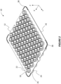
- FIG 1 shows a transport tray 10 according to the present disclosure from above.
- the transport tray 10 includes a plate portion 12 and a plurality of sleeves 14.
- the sleeves 14 are each configured to receive a substantially cylindrical container 16 having a cylindrical container wall 18 and a container bottom surface 20 arranged orthogonally to the container wall 18 ( Figure 4A ).
- the containers 16 can serve as primary packaging for various types of end products.
- primary packaging can encompass vials, cartridges, ampoules, bottles, and syringes to name a few examples, the figures of the present disclosure illustrate vials.
- the transport tray 10 can be used to group and transport the vials 16 throughout different manufacturing processes, for example.
- each sleeve 14 includes a top opening 22, a bottom opening 24, a sleeve wall 26 that extends along a sleeve axis between the top opening 22 and the bottom opening 24.
- the sleeve axis of each sleeve 14 extends along the Z-axis.
- Figures 3 and 4 show the transport tray 10 of Figures 1 and 2 with a plurality of containers 16 arranged in the sleeves 14.
- the containers 16 are arranged in the sleeves 14 such that the sleeve wall 26 faces the container wall 18 ( Figure 4A ).
- the container 16 includes an opening 17 that is arranged facing the top opening 22 of the sleeve 14, while the bottom surface 20 of the container is adj acent to the bottom opening 24 of the sleeve 14.
- Each sleeve 14 includes one or more support feet 28 that are adjacent to the bottom opening 24 and extend from the sleeve wall 26 towards the sleeve axis.
- Each support foot 28 comprises a bottom surface 28a and a top surface 28b configured to abut the container bottom surface 20 of the container 16 received in the sleeve.
- the support foot 28 is designed so that a gap G is formed between the support foot bottom surface 28a and the container bottom surface 20 along the sleeve axis ( Figure 4B ).
- the transport tray 10 rests on the collective support foot bottom surfaces 28a of each of the support feet 28, while each container bottom surface 20 rests entirely on the support foot top surfaces 28b of the support feet 28 in a respective sleeve 14.
- the container bottom surface 20 does not extend past the support feet 28.
- the container bottom surface 20 is separated from the surface on which the transport tray 10 rests. In practice, this may mean that the support foot top surface 28b makes contact with the lowest point of the container bottom surface 20.
- the one or more support feet 28 include a thermally conductive polymer.
- the one or more support feet 28 are formed as a single part, e.g., of injection molded plastic with thermally conductive fillers. Such support feet 28 may be attached to the sleeves 14 using insert molding techniques.
- the filler may include an aluminum filler, a zinc filler, or a combination thereof.
- the one or more support feet 28 can be attached to the bottom opening 24 by a ring 29 ( Figure 3 ).
- the ring 29 may also include a thermally conductive polymer.
- the ring 29 and the one or more support feet 28 may be integrally formed, i.e., form a monolithic structure.
- the entire sleeve 14, or even the entire support tray 10 may be a monolithic structure.
- the transport tray 10 may be manufactured by injection molding a thermally conductive polymer. As described above, the container bottom surface 20 rests on the support foot top surfaces 28b of each sleeve 14.
- the transport tray 10 may be used during a lyophilization process with the containers 16 remaining in the sleeves 14. Since the container bottom surface 20 does not protrude through the bottom opening 24 of the sleeve 14, the same transport tray 10 can be used for other processes, e.g., a direct fill process. Thus, the transport tray 10 according to the present disclosure may contribute to the efficiency of the manufacturing process for primary packaging.
- the transport tray 10 may include any number of the following features that may improve the robustness and heat transfer of the transport tray 10.
- each sleeve wall 26 may include a closed cylinder that completely encircles the sleeve axis and, thus, a portion of the container wall 18.
- this closed cylinder design can increase the amount of thermally conductive polymer that surrounds the container wall 18 and improve heat transfer, e.g., during the lyophilization process.
- the closed cylinder may improve the robustness of the sleeve 14 and transport tray 10, respectively.
- each sleeve 14 may be larger than the bottom opening 24, such that the sleeve wall forms an angle greater than 0° relative to the sleeve axis. Such a taper may make it easier to retrieve the container 16 from the sleeve 14 despite the closed cylinder design described above.
- the transport tray 10 may include a connecting portion 30 that connects the sleeve walls 26 of at least two adjacent sleeves to the plate portion 12.
- the connecting portion 30 can also increase the volume of thermally conductive polymer and, thus, the heat transfer through the transport tray 10 and its overall robustness.
- Figures 5A to 5C show optional features of the transport tray 10 that may enable several transport trays 10 to be neatly stacked next to one another.
- a first and second transport tray 10 are each loaded with a plurality of containers 16 and placed next to one another on a table 32.
- the table 32 may be used for a lyophilization process to rapidly cool the containers 16 and their contents.
- FIG. 5A shows a scenario in which adjacent transport trays 10 have been placed so closely together that the plate portions 12 overlap. This overlap in the plate portions creates a gap 34 between the table 32 and the transport tray 10 on the right. This gap 34 may reduce the efficiency of the heat transfer between the table 32, the transport tray 10, and the containers 16.
- each corner region 36 of the plate portion 12 may be provided with one or more features that reduce the likelihood that adjacent transport trays 10 overlap one another.
- each corner region 36 of the plate portion 12 includes a raised bumper 38.
- "raised” can mean that a height of the bumper 38 along the Z-axis is greater than a thickness of the plate portion 12 along the Z-axis.
- the raised bumper 38 can include a first and a second projection 40 that increase the stability of the raised bumper 38.
- the first projection 40 extends outward from the plate portion 12 along the X-axis
- the second projection 40 extends outward from the plate portion 12 along the Y-axis.
- the raised bumper 38 can include a strip of material that continuously wraps around the corner region 36 of the plate portion. Each end of the raised bumper 38 can abut an edge portion 42 of the plate portion 12 that does not have an increased thickness (see also Figure 2 ). The combination of alternating raised bumpers 38 and edge portions 42 improves air flow during injection molding of the transport tray 10.
Landscapes
- Engineering & Computer Science (AREA)
- Mechanical Engineering (AREA)
- Health & Medical Sciences (AREA)
- Life Sciences & Earth Sciences (AREA)
- Animal Behavior & Ethology (AREA)
- General Health & Medical Sciences (AREA)
- Public Health (AREA)
- Veterinary Medicine (AREA)
- General Engineering & Computer Science (AREA)
- Manufacturing & Machinery (AREA)
- Ceramic Engineering (AREA)
- Chemical Kinetics & Catalysis (AREA)
- Biomedical Technology (AREA)
- Molecular Biology (AREA)
- Clinical Laboratory Science (AREA)
- Pharmacology & Pharmacy (AREA)
- Vascular Medicine (AREA)
- Anesthesiology (AREA)
- Chemical & Material Sciences (AREA)
- Heart & Thoracic Surgery (AREA)
- Hematology (AREA)
- Stackable Containers (AREA)
- Packaging Frangible Articles (AREA)
- Pallets (AREA)
- Packaging Of Annular Or Rod-Shaped Articles, Wearing Apparel, Cassettes, Or The Like (AREA)
Description
- This disclosure relates to a tray for transporting packaging units.
- In industrial contexts, products are generally transported and sold in packaging units. Packaging units can include vials, cartridges, ampoules, bottles, or pre-fillable syringes. In many industries, these different types of packaging units are collectively known as "primary packaging," i.e., the packaging that comes into direct contact with an end product. The end product may be a food product, a cosmetic product, or a pharmaceutical product. Primary packaging can undergo numerous manufacturing processes before being filled with the end product. During these processes, primary packaging is often transported and processed in batches.
-
US 10,703,539 B2 -
US 2018/0208377 A1 describes a supporting structure that has an upper side or base plane, which generally is formed as a plate and whose circumferential edge is formed flat. In the upper side, a plurality of openings is formed, which are arranged in rows and columns extending perpendicular to each other. The openings of adjacent rows or columns are arranged staggered relative to each other, which enables a higher packing density with the hexagonal arrangement of the peripheral webs. A plurality of axial connecting webs protrude perpendicularly from the underside of the supporting structure, which are connected to each other at their lower ends via circumferential bottom webs. -
WO 2014/130349 A1 describes a tray with receptacles that are configured to support vials in different manners during different stages of processing. Each receptacle has a bottom opening defined at a bottom edge of lower portion of a cylindrical wall, and an inwardly extending lip surrounding each opening. The opening has an inner diameter slightly smaller than the outer diameter of the vial side wall, but slightly larger than the bottom wall, such that the inner edges of lip contact a portion of curved lower edge joining side wall and bottom wall. This configuration permits the vial to be supported by the tray while suspended, with a lower portion of the vial protruding downward from the bottom edge of the tray. -
WO 2011/135085 A1 , which accords with the preamble of claim 1, describes a packaging structure for containers for pharmaceutical use, comprising a tray having an open side for introducing and extracting a support plane of the containers, and a closing element of the open side of the tray, said support plane having a spatial prefixed distribution of seats in which said containers can be precisely positioned without mutual contact, whereby the structure comprises diversification means of the engaging configuration between said support plane and said tray in order to maintain unchanged the points inside the tray in which an end of the containers is placed, with the variation of the height of the containers associated from time to time to the support plane. - Aspects of the present disclosure aim to alleviate problems associated with known transport trays.
- A transport tray according to the present invention is set out in claim 1. Further advantageous developments of the present invention are set out in the dependent claims. According to the present invention, a transport tray includes a plurality of sleeves that are each configured to receive a substantially cylindrical container having a cylindrical container wall and a container bottom surface arranged orthogonally to the container wall. Each sleeve includes a top opening, a bottom opening, a sleeve wall that extends along a sleeve axis between the top opening and the bottom opening and is configured to abut at least a portion of the container wall of a respective container, and one or more support feet that are adjacent to the bottom opening and extend from the sleeve wall towards the sleeve axis, wherein each support foot comprises a bottom surface and a top surface configured to abut the container bottom surface of a respective container, such that a gap is formed between the support foot bottom surface and the container bottom surface along the sleeve axis. The one or more support feet comprise a thermally conductive polymer;wherein the transport tray further comprises a plate portion connected to the top opening of each sleeve and comprising a plurality of comer regions, and a raised bumper arranged at least at each corner region of the plate portion, wherein the raised bumper has a height that is greater than a thickness of the plate portion; and wherein a perimeter of the plate portion comprises the raised bumpers and an edge portion having the same thickness as the plate portion arranged between each pair of adjacent raised bumpers.
- In some instances, each sleeve can include a ring that connects the one or more support feet to the bottom opening and that comprises a thermally conductive polymer. Further, each sleeve can be a monolithic structure that comprises a thermally conductive polymer.
- In addition to the respective sleeves, the entire transport tray may be a monolithic structure that comprises a thermally conductive polymer. For example, the transport tray may be manufactured by injection molding a thermally conductive polymer.
- The thermally conductive polymer may comprise an aluminum filler, a zinc filler, or a combination thereof.
- Each sleeve wall may include a closed cylinder that encircles the sleeve axis.
- The top opening of each sleeve may be larger than the bottom opening, such that the sleeve wall forms an angle greater than 0° relative to the sleeve axis.
- According to the present invention, the transport tray includes a plate portion connected to the top opening of each sleeve. Preferably, a connecting portion may connect the sleeve walls of at least two adjacent sleeves to the plate portion. According to the present invention, the plate portion comprises a plurality of corner regions and a raised bumper arranged at each corner region. Such a raised bumper has a height that is greater than a thickness of the plate portion. Preferably, each raised bumper may include at least one projection that extends outward from a perimeter of the plate portion. According to the present invention, the perimeter of the plate portion includes the raised bumpers and an edge portion having the same thickness as the plate portion arranged between each pair of adjacent raised bumpers.
- These and other embodiments described herein may provide one or more of the following benefits. The transport tray may be suitable for transferring heat to and from the packaging units. For example, the transport tray may be used in a lyophilization process. At the same time, the transport tray may securely support the packaging units in other processes, such as direct filling processes. Overall, the transport tray may reduce the need to handle individual packaging units during the manufacturing process. Further, the design of the transport tray may be compatible with existing equipment. The transport tray may also prove to be robust.
- Certain embodiments will now be described, by way of example only, with reference to the accompanying drawings, in which:
-
Figure 1 shows a transport tray according to the present disclosure from above; -
Figure 2 shows a perspective view of the transport tray ofFigure 1 ; -
Figure 3 shows a partial perspective view of a bottom of the transport tray ofFigure 1 ; -
Figures 4A and4B show cross-sectional views through the transport tray ofFigures 1 to 3 ; -
Figures 5A and5B schematically show multiple transport trays placed next to one another on a table; and -
Figure 5C shows a partial perspective view of the transport tray ofFigure 2 . - Like reference numbers and designations in the various drawings indicate like elements.
-
Figure 1 shows atransport tray 10 according to the present disclosure from above. Thetransport tray 10 includes aplate portion 12 and a plurality ofsleeves 14. Thesleeves 14 are each configured to receive a substantiallycylindrical container 16 having acylindrical container wall 18 and acontainer bottom surface 20 arranged orthogonally to the container wall 18 (Figure 4A ). Thecontainers 16 can serve as primary packaging for various types of end products. Although the expression "primary packaging" can encompass vials, cartridges, ampoules, bottles, and syringes to name a few examples, the figures of the present disclosure illustrate vials. Thetransport tray 10 can be used to group and transport thevials 16 throughout different manufacturing processes, for example. - As shown in
Figure 2 , eachsleeve 14 includes a top opening 22, a bottom opening 24, asleeve wall 26 that extends along a sleeve axis between the top opening 22 and the bottom opening 24. Referring to the coordinate axes shown inFigure 2 , the sleeve axis of eachsleeve 14 extends along the Z-axis. -
Figures 3 and4 show thetransport tray 10 ofFigures 1 and2 with a plurality ofcontainers 16 arranged in thesleeves 14. Thecontainers 16 are arranged in thesleeves 14 such that thesleeve wall 26 faces the container wall 18 (Figure 4A ). Thecontainer 16 includes anopening 17 that is arranged facing the top opening 22 of thesleeve 14, while thebottom surface 20 of the container is adj acent to the bottom opening 24 of thesleeve 14. Eachsleeve 14 includes one ormore support feet 28 that are adjacent to the bottom opening 24 and extend from thesleeve wall 26 towards the sleeve axis. Eachsupport foot 28 comprises abottom surface 28a and atop surface 28b configured to abut thecontainer bottom surface 20 of thecontainer 16 received in the sleeve. Thesupport foot 28 is designed so that a gap G is formed between the supportfoot bottom surface 28a and thecontainer bottom surface 20 along the sleeve axis (Figure 4B ). - Accordingly, the
transport tray 10 rests on the collective support foot bottom surfaces 28a of each of thesupport feet 28, while eachcontainer bottom surface 20 rests entirely on the support foot top surfaces 28b of thesupport feet 28 in arespective sleeve 14. As shown inFigures 4A and4B , thecontainer bottom surface 20 does not extend past thesupport feet 28. In other words, thecontainer bottom surface 20 is separated from the surface on which thetransport tray 10 rests. In practice, this may mean that the support foottop surface 28b makes contact with the lowest point of thecontainer bottom surface 20. - According to the present disclosure, the one or
more support feet 28 include a thermally conductive polymer. For example, the one ormore support feet 28 are formed as a single part, e.g., of injection molded plastic with thermally conductive fillers.Such support feet 28 may be attached to thesleeves 14 using insert molding techniques. For example, the filler may include an aluminum filler, a zinc filler, or a combination thereof. In some instances, the one ormore support feet 28 can be attached to thebottom opening 24 by a ring 29 (Figure 3 ). Thering 29 may also include a thermally conductive polymer. Thering 29 and the one ormore support feet 28 may be integrally formed, i.e., form a monolithic structure. In some instances, theentire sleeve 14, or even theentire support tray 10, may be a monolithic structure. For example, thetransport tray 10 may be manufactured by injection molding a thermally conductive polymer. As described above, thecontainer bottom surface 20 rests on the support foot top surfaces 28b of eachsleeve 14. - Since at least the one or
more support feet 28 include thermally conductive polymer, thesupport feet 28 are able to transfer heat to and from thecontainer bottom surface 20. Accordingly, thetransport tray 10 may be used during a lyophilization process with thecontainers 16 remaining in thesleeves 14. Since thecontainer bottom surface 20 does not protrude through thebottom opening 24 of thesleeve 14, thesame transport tray 10 can be used for other processes, e.g., a direct fill process. Thus, thetransport tray 10 according to the present disclosure may contribute to the efficiency of the manufacturing process for primary packaging. - The
transport tray 10 may include any number of the following features that may improve the robustness and heat transfer of thetransport tray 10. - As shown in
Figure 3 , for example, eachsleeve wall 26 may include a closed cylinder that completely encircles the sleeve axis and, thus, a portion of thecontainer wall 18. In cases in which theentire sleeve 14 includes a thermally conductive polymer, this closed cylinder design can increase the amount of thermally conductive polymer that surrounds thecontainer wall 18 and improve heat transfer, e.g., during the lyophilization process. At the same time, the closed cylinder may improve the robustness of thesleeve 14 andtransport tray 10, respectively. - The
top opening 22 of eachsleeve 14 may be larger than thebottom opening 24, such that the sleeve wall forms an angle greater than 0° relative to the sleeve axis. Such a taper may make it easier to retrieve thecontainer 16 from thesleeve 14 despite the closed cylinder design described above. - As shown in
Figure 4A , thetransport tray 10 may include a connectingportion 30 that connects thesleeve walls 26 of at least two adjacent sleeves to theplate portion 12. The connectingportion 30 can also increase the volume of thermally conductive polymer and, thus, the heat transfer through thetransport tray 10 and its overall robustness. -
Figures 5A to 5C show optional features of thetransport tray 10 that may enableseveral transport trays 10 to be neatly stacked next to one another. As shown inFigure 5A , a first andsecond transport tray 10 are each loaded with a plurality ofcontainers 16 and placed next to one another on a table 32. For example, the table 32 may be used for a lyophilization process to rapidly cool thecontainers 16 and their contents. - As shown in the enlarged portion of
Figure 5A , theplate portions 12 of eachtransport tray 10 are arranged closely next to each other without touching. Such an arrangement may allow the greatest possible number ofcontainers 16 to be placed on the table at once.Figure 5B shows a scenario in whichadjacent transport trays 10 have been placed so closely together that theplate portions 12 overlap. This overlap in the plate portions creates agap 34 between the table 32 and thetransport tray 10 on the right. Thisgap 34 may reduce the efficiency of the heat transfer between the table 32, thetransport tray 10, and thecontainers 16. - In order to prevent the overlap shown in
Figure 5B , each corner region 36 of theplate portion 12 may be provided with one or more features that reduce the likelihood thatadjacent transport trays 10 overlap one another. As shown inFigure 5C , each corner region 36 of theplate portion 12 includes a raisedbumper 38. In the context of this disclosure, "raised" can mean that a height of thebumper 38 along the Z-axis is greater than a thickness of theplate portion 12 along the Z-axis. When twotransport trays 10 are brought close together, the matchingbumpers 38 may come into contact and prevent theplate portions 12 from overlapping. - In some instances, the raised
bumper 38 can include a first and asecond projection 40 that increase the stability of the raisedbumper 38. InFigure 5C , thefirst projection 40 extends outward from theplate portion 12 along the X-axis, and thesecond projection 40 extends outward from theplate portion 12 along the Y-axis. - The raised
bumper 38 can include a strip of material that continuously wraps around the corner region 36 of the plate portion. Each end of the raisedbumper 38 can abut anedge portion 42 of theplate portion 12 that does not have an increased thickness (see alsoFigure 2 ). The combination of alternating raisedbumpers 38 andedge portions 42 improves air flow during injection molding of thetransport tray 10. - A number of embodiments have been described. Nevertheless, numerous alternative embodiments within the scope of the claims will be readily appreciated by those skilled in the art. The presently described embodiments are not to be taken as limiting the scope of the invention that is defined by the claims.
Claims (11)
- A transport tray (10) comprisesa plurality of sleeves (14), wherein each sleeve (14) is configured to receive a substantially cylindrical container (16) having a cylindrical container wall (18) and a container bottom surface (20) arranged orthogonally to the container wall (18);wherein each sleeve (14) comprisesa top opening (22),a bottom opening (24),a sleeve wall (26) that extends along a sleeve axis between the top opening (22) and the bottom opening (24) and is configured to abut at least a portion of the container wall (18) of a respective container (16), andone or more support feet (28) that are adjacent to the bottom opening (24) and extend from the sleeve wall (26) towards the sleeve axis, wherein each support foot (28) comprises a bottom surface (28a) and a top surface (28b) configured to abut the container bottom surface (20) of a respective container (16), such that a gap (G) is formed between the support foot bottom surface (28a) and the container bottom surface (20) along the sleeve axis, characterized in that the one or more support feet (28) comprise a thermally conductive polymer;wherein the transport tray (10) further comprisesa plate portion (12) connected to the top opening (22) of each sleeve (14) and comprising a plurality of corner regions, anda raised bumper (38) arranged at least at each corner region of the plate portion (12), wherein the raised bumper (38) has a height that is greater than a thickness of the plate portion (12); andwherein a perimeter of the plate portion (12) comprises the raised bumpers (38) and an edge portion (42) having the same thickness as the plate portion (12) arranged between each pair of adjacent raised bumpers (38).
- The transport tray (10) according to claim 1, wherein each sleeve (14) further comprises a ring (29) that connects the one or more support feet (28) to the bottom opening (24), wherein the ring (29) comprises a thermally conductive polymer.
- The transport tray (10) according to claim 2, wherein each sleeve (14) is a monolithic structure that comprises a thermally conductive polymer.
- The transport tray (10) according to claim 3, wherein the transport tray (10) is a monolithic structure that comprises a thermally conductive polymer.
- The transport tray (10) according to claim 4, wherein the transport tray (10) is manufactured by injection molding a thermally conductive polymer.
- The transport tray (10) according to any one of claims 1 to 5, wherein the thermally conductive polymer comprises an aluminum filler.
- The transport tray (10) according to any one of the preceding claims, wherein the thermally conductive polymer comprises a zinc filler.
- The transport tray (10) according to any one of the preceding claims, wherein each sleeve wall (26) comprises a closed cylinder that encircles the sleeve axis.
- The transport tray (10) according to any one of the preceding claims, wherein the top opening (22) of each sleeve (14) is larger than the bottom opening (24), such that the sleeve wall (26) forms an angle greater than 0° relative to the sleeve axis.
- The transport tray (10) according to any one of the preceding claims, further comprising:
a connecting portion (30) that connects the sleeve walls (26) of at least two adjacent sleeves (14) to the plate portion (12). - The transport tray (10) according to claim 1, wherein each raised bumper (38) comprises at least one projection (40) that extends outward from the perimeter of the plate portion (12).
Applications Claiming Priority (1)
| Application Number | Priority Date | Filing Date | Title |
|---|---|---|---|
| US202163190086P | 2021-05-18 | 2021-05-18 |
Publications (2)
| Publication Number | Publication Date |
|---|---|
| EP4091648A1 EP4091648A1 (en) | 2022-11-23 |
| EP4091648B1 true EP4091648B1 (en) | 2024-10-02 |
Family
ID=82218351
Family Applications (1)
| Application Number | Title | Priority Date | Filing Date |
|---|---|---|---|
| EP22174019.4A Active EP4091648B1 (en) | 2021-05-18 | 2022-05-18 | Transport tray for packaging units |
Country Status (8)
| Country | Link |
|---|---|
| US (1) | US20220371765A1 (en) |
| EP (1) | EP4091648B1 (en) |
| CN (1) | CN115447877B (en) |
| CA (1) | CA3159082C (en) |
| ES (1) | ES2993324T3 (en) |
| HU (1) | HUE069014T2 (en) |
| MX (1) | MX2022005986A (en) |
| PL (1) | PL4091648T3 (en) |
Families Citing this family (9)
| Publication number | Priority date | Publication date | Assignee | Title |
|---|---|---|---|---|
| US12098018B2 (en) * | 2021-01-15 | 2024-09-24 | Oyster Point Pharma, Inc. | Nesting structures for storage, transport, and assembly of drug dispensers and containers |
| US20240067396A1 (en) * | 2021-01-26 | 2024-02-29 | Becton Dickinson France | Nest for the Packaging of Plunger Stoppers With Stacking Pins Ensuring a Reliable Alignment of a Pile of Nests |
| US12319466B2 (en) | 2021-05-18 | 2025-06-03 | Gerresheimer Glas Gmbh | Transporting packaging units |
| MX2022005963A (en) | 2021-05-18 | 2023-03-01 | Gerresheimer Glas Gmbh | Container for packaging units. |
| US12286270B2 (en) | 2021-05-18 | 2025-04-29 | Gerresheimer Glas Gmbh | Transporting packaging units |
| EP4516335A1 (en) * | 2023-08-29 | 2025-03-05 | Becton Dickinson France | Packaging system for transporting medical devices and method of forming such a packaging system |
| EP4516336A1 (en) * | 2023-08-29 | 2025-03-05 | Becton Dickinson France | Device and packaging system for transporting medical devices |
| USD1119281S1 (en) * | 2024-04-15 | 2026-03-24 | SCHOTI Pharma Schweiz AG | Portion of a holding structure for pharmaceutical containers |
| TWI895070B (en) * | 2024-08-15 | 2025-08-21 | 振鋒企業股份有限公司 | Electronic device carrier |
Family Cites Families (26)
| Publication number | Priority date | Publication date | Assignee | Title |
|---|---|---|---|---|
| US2702647A (en) * | 1952-04-18 | 1955-02-22 | Albert Wesling And Sons Inc | Material handling tray |
| GB2056262B (en) * | 1979-05-03 | 1984-02-22 | Borden Uk Ltd | Container |
| US4722440A (en) * | 1987-03-23 | 1988-02-02 | Chrysler Motors Corporation | Tray for transporting internal combustion engine pistons |
| JPH0761445A (en) * | 1993-08-20 | 1995-03-07 | Daifuku Co Ltd | Sealed-up conveyance device |
| KR200245725Y1 (en) * | 1999-05-14 | 2001-09-25 | 정 웅 최 | A Damp-Proof Panel for the Basement |
| JP2005522710A (en) * | 2002-04-15 | 2005-07-28 | クール オプションズ,インコーポレーテッド | Thermally conductive bioassay tray |
| US20090004064A1 (en) * | 2007-06-27 | 2009-01-01 | Applera Corporation | Multi-material microplate and method |
| US7823725B1 (en) * | 2008-01-24 | 2010-11-02 | Triad Packaging, Inc. | Shipping and display pallet assembly |
| US20110086141A1 (en) * | 2009-10-14 | 2011-04-14 | Erik Strilich | Package for Cushioning Food Product |
| US8157090B2 (en) * | 2009-10-23 | 2012-04-17 | Baker Hughes Incorporated | Ball tray organizer for subterranean complex completions |
| IT1399750B1 (en) * | 2010-04-30 | 2013-05-03 | Stevanato Group Internat As | PACKAGING STRUCTURE FOR PHARMACEUTICAL CONTAINERS |
| WO2014130349A1 (en) | 2013-02-21 | 2014-08-28 | Capitol Medical Devices, Inc. | Vial, tray, and vial processing assembly |
| US10029261B2 (en) * | 2013-11-05 | 2018-07-24 | Biotix, Inc. | Pipette tip rack plates |
| MX354768B (en) * | 2013-12-20 | 2018-03-21 | Buckhorn Inc | Collapsible container having foldable side and end panels. |
| ES2550533B1 (en) * | 2014-05-08 | 2016-09-08 | Ribawood S.A. | BOTTLE PALETIZATION TRAY, IMPROVED |
| EP3261951B1 (en) * | 2015-02-23 | 2019-11-27 | Nuova Ompi S.r.l. | Packaging structure for containers for pharmaceutical use |
| JP6474668B2 (en) * | 2015-04-03 | 2019-02-27 | 三甲株式会社 | Wheel transport unit |
| KR102009119B1 (en) * | 2015-09-04 | 2019-08-08 | 가부시끼가이샤 다이쿄 세이코 | Container Holding Member and Medical Container Set |
| DE102016123147A1 (en) | 2016-11-30 | 2018-05-30 | Schott Ag | Support structure for simultaneously holding a plurality of vials, use thereof, and methods of treating such vials |
| DE102017101398A1 (en) | 2017-01-25 | 2018-07-26 | Schott Schweiz Ag | Support structure for simultaneously holding a plurality of containers for substances for pharmaceutical, medical or cosmetic applications, transport structures and transport or packaging containers with selbiger |
| CN207045959U (en) * | 2017-08-18 | 2018-02-27 | 衡阳力赛储能有限公司 | A kind of cylindrical battery pallet |
| JP6694486B2 (en) * | 2018-03-29 | 2020-05-13 | バイオティクス, インコーポレイテッド | Pipette tip tray with increased rigidity |
| DE102018111491A1 (en) * | 2018-05-14 | 2019-11-14 | Schott Schweiz Ag | Support structure for simultaneously holding a plurality of containers for substances for pharmaceutical, medical or cosmetic applications, transport structures and transport or packaging containers with selbiger |
| CN208761268U (en) * | 2018-07-25 | 2019-04-19 | 广州欧派集成家居有限公司 | Corner protector and protection combination |
| CN210285018U (en) * | 2019-06-15 | 2020-04-10 | 青岛雨辰包装有限公司 | Plastic uptake tray capable of preventing product from being crushed |
| CN212654814U (en) * | 2020-05-29 | 2021-03-05 | 环达电脑(上海)有限公司 | Anti-collision device |
-
2022
- 2022-05-17 MX MX2022005986A patent/MX2022005986A/en unknown
- 2022-05-17 US US17/746,588 patent/US20220371765A1/en active Pending
- 2022-05-17 CA CA3159082A patent/CA3159082C/en active Active
- 2022-05-18 ES ES22174019T patent/ES2993324T3/en active Active
- 2022-05-18 EP EP22174019.4A patent/EP4091648B1/en active Active
- 2022-05-18 HU HUE22174019A patent/HUE069014T2/en unknown
- 2022-05-18 PL PL22174019.4T patent/PL4091648T3/en unknown
- 2022-05-18 CN CN202210538010.5A patent/CN115447877B/en active Active
Also Published As
| Publication number | Publication date |
|---|---|
| CN115447877B (en) | 2025-03-14 |
| CA3159082C (en) | 2026-04-21 |
| MX2022005986A (en) | 2023-01-24 |
| CA3159082A1 (en) | 2022-11-18 |
| EP4091648A1 (en) | 2022-11-23 |
| ES2993324T3 (en) | 2024-12-27 |
| US20220371765A1 (en) | 2022-11-24 |
| HUE069014T2 (en) | 2025-02-28 |
| CN115447877A (en) | 2022-12-09 |
| PL4091648T3 (en) | 2025-01-07 |
Similar Documents
| Publication | Publication Date | Title |
|---|---|---|
| EP4091648A1 (en) | Transport tray for packaging units | |
| US12465552B2 (en) | Supporting structure for concurrently supporting a plurality of containers for substances for pharmaceutical, medical or cosmetic applications, and transport structure comprising the same | |
| US11498709B2 (en) | Method for closing cartridges, supporting structure for supporting cartridge closures and transport or packaging container | |
| EP3653526B1 (en) | Holding structure with a plurality of containers held thereon for substances for pharmaceutical, medical or cosmetic applications, and transport or packaging container having same | |
| RU2579742C2 (en) | Package for containers | |
| US10703539B2 (en) | Supporting structure for concurrently supporting a plurality of vials, use thereof and process for the treatment of such vials | |
| US8235214B2 (en) | Stackable liquid container with tunnel-shaped base | |
| CN108341142A (en) | Support support construction, transport structure and transport or the packing container of multiple containers | |
| US10472164B2 (en) | Tri-fold egg carton for various size jumbo eggs | |
| HU220513B1 (en) | Package tray for bottles | |
| MXPA06011896A (en) | Nestable crate for containers. | |
| US7543705B2 (en) | Container with anti-nesting ledge | |
| EP4311564A1 (en) | Support device for supporting a plurality of containers for pharmaceutical use to be handled in a processing line | |
| EP4311562A1 (en) | Support device for supporting a plurality of containers for pharmaceutical use to be handled in a processing line | |
| US20220081158A1 (en) | Integrated tray and pallet system | |
| EP4311563A1 (en) | Support device for supporting a plurality of containers for pharmaceutical use to be handled in a processing line | |
| US11345529B2 (en) | Packaging insert for individual containers | |
| US20120261291A1 (en) | Stable stacked multipack assembly including stackable packing units and method for providing same | |
| AU2014206224A1 (en) | System for the transport of an array of a plurality of self-supporting containers for liquids | |
| JPH04367434A (en) | Thin wall container |
Legal Events
| Date | Code | Title | Description |
|---|---|---|---|
| PUAI | Public reference made under article 153(3) epc to a published international application that has entered the european phase |
Free format text: ORIGINAL CODE: 0009012 |
|
| STAA | Information on the status of an ep patent application or granted ep patent |
Free format text: STATUS: REQUEST FOR EXAMINATION WAS MADE |
|
| 17P | Request for examination filed |
Effective date: 20220518 |
|
| AK | Designated contracting states |
Kind code of ref document: A1 Designated state(s): AL AT BE BG CH CY CZ DE DK EE ES FI FR GB GR HR HU IE IS IT LI LT LU LV MC MK MT NL NO PL PT RO RS SE SI SK SM TR |
|
| REG | Reference to a national code |
Ref country code: DE Ref legal event code: R079 Free format text: PREVIOUS MAIN CLASS: A61M0005000000 Ipc: A61J0001160000 Ref document number: 602022006459 Country of ref document: DE |
|
| GRAP | Despatch of communication of intention to grant a patent |
Free format text: ORIGINAL CODE: EPIDOSNIGR1 |
|
| STAA | Information on the status of an ep patent application or granted ep patent |
Free format text: STATUS: GRANT OF PATENT IS INTENDED |
|
| RIC1 | Information provided on ipc code assigned before grant |
Ipc: A61J 1/06 20060101ALI20231208BHEP Ipc: B01L 9/06 20060101ALI20231208BHEP Ipc: A61M 5/00 20060101ALI20231208BHEP Ipc: A61J 1/16 20060101AFI20231208BHEP Ipc: B65D 25/10 20060101ALI20231208BHEP |
|
| INTG | Intention to grant announced |
Effective date: 20240105 |
|
| GRAJ | Information related to disapproval of communication of intention to grant by the applicant or resumption of examination proceedings by the epo deleted |
Free format text: ORIGINAL CODE: EPIDOSDIGR1 |
|
| STAA | Information on the status of an ep patent application or granted ep patent |
Free format text: STATUS: REQUEST FOR EXAMINATION WAS MADE |
|
| GRAS | Grant fee paid |
Free format text: ORIGINAL CODE: EPIDOSNIGR3 |
|
| STAA | Information on the status of an ep patent application or granted ep patent |
Free format text: STATUS: GRANT OF PATENT IS INTENDED |
|
| GRAP | Despatch of communication of intention to grant a patent |
Free format text: ORIGINAL CODE: EPIDOSNIGR1 |
|
| INTC | Intention to grant announced (deleted) | ||
| INTG | Intention to grant announced |
Effective date: 20240524 |
|
| GRAA | (expected) grant |
Free format text: ORIGINAL CODE: 0009210 |
|
| STAA | Information on the status of an ep patent application or granted ep patent |
Free format text: STATUS: THE PATENT HAS BEEN GRANTED |
|
| AK | Designated contracting states |
Kind code of ref document: B1 Designated state(s): AL AT BE BG CH CY CZ DE DK EE ES FI FR GB GR HR HU IE IS IT LI LT LU LV MC MK MT NL NO PL PT RO RS SE SI SK SM TR |
|
| REG | Reference to a national code |
Ref country code: GB Ref legal event code: FG4D |
|
| REG | Reference to a national code |
Ref country code: CH Ref legal event code: EP |
|
| P01 | Opt-out of the competence of the unified patent court (upc) registered |
Free format text: CASE NUMBER: APP_50507/2024 Effective date: 20240905 |
|
| REG | Reference to a national code |
Ref country code: DE Ref legal event code: R096 Ref document number: 602022006459 Country of ref document: DE |
|
| REG | Reference to a national code |
Ref country code: IE Ref legal event code: FG4D |
|
| REG | Reference to a national code |
Ref country code: ES Ref legal event code: FG2A Ref document number: 2993324 Country of ref document: ES Kind code of ref document: T3 Effective date: 20241227 |
|
| REG | Reference to a national code |
Ref country code: SK Ref legal event code: T3 Ref document number: E 45363 Country of ref document: SK |
|
| REG | Reference to a national code |
Ref country code: LT Ref legal event code: MG9D |
|
| REG | Reference to a national code |
Ref country code: NL Ref legal event code: MP Effective date: 20241002 |
|
| REG | Reference to a national code |
Ref country code: HU Ref legal event code: AG4A Ref document number: E069014 Country of ref document: HU |
|
| REG | Reference to a national code |
Ref country code: AT Ref legal event code: MK05 Ref document number: 1727964 Country of ref document: AT Kind code of ref document: T Effective date: 20241002 |
|
| PG25 | Lapsed in a contracting state [announced via postgrant information from national office to epo] |
Ref country code: NL Free format text: LAPSE BECAUSE OF FAILURE TO SUBMIT A TRANSLATION OF THE DESCRIPTION OR TO PAY THE FEE WITHIN THE PRESCRIBED TIME-LIMIT Effective date: 20241002 |
|
| PG25 | Lapsed in a contracting state [announced via postgrant information from national office to epo] |
Ref country code: NL Free format text: LAPSE BECAUSE OF FAILURE TO SUBMIT A TRANSLATION OF THE DESCRIPTION OR TO PAY THE FEE WITHIN THE PRESCRIBED TIME-LIMIT Effective date: 20241002 |
|
| PG25 | Lapsed in a contracting state [announced via postgrant information from national office to epo] |
Ref country code: HR Free format text: LAPSE BECAUSE OF FAILURE TO SUBMIT A TRANSLATION OF THE DESCRIPTION OR TO PAY THE FEE WITHIN THE PRESCRIBED TIME-LIMIT Effective date: 20241002 Ref country code: IS Free format text: LAPSE BECAUSE OF FAILURE TO SUBMIT A TRANSLATION OF THE DESCRIPTION OR TO PAY THE FEE WITHIN THE PRESCRIBED TIME-LIMIT Effective date: 20250202 Ref country code: PT Free format text: LAPSE BECAUSE OF FAILURE TO SUBMIT A TRANSLATION OF THE DESCRIPTION OR TO PAY THE FEE WITHIN THE PRESCRIBED TIME-LIMIT Effective date: 20250203 |
|
| PG25 | Lapsed in a contracting state [announced via postgrant information from national office to epo] |
Ref country code: FI Free format text: LAPSE BECAUSE OF FAILURE TO SUBMIT A TRANSLATION OF THE DESCRIPTION OR TO PAY THE FEE WITHIN THE PRESCRIBED TIME-LIMIT Effective date: 20241002 |
|
| PG25 | Lapsed in a contracting state [announced via postgrant information from national office to epo] |
Ref country code: BG Free format text: LAPSE BECAUSE OF FAILURE TO SUBMIT A TRANSLATION OF THE DESCRIPTION OR TO PAY THE FEE WITHIN THE PRESCRIBED TIME-LIMIT Effective date: 20241002 |
|
| PG25 | Lapsed in a contracting state [announced via postgrant information from national office to epo] |
Ref country code: NO Free format text: LAPSE BECAUSE OF FAILURE TO SUBMIT A TRANSLATION OF THE DESCRIPTION OR TO PAY THE FEE WITHIN THE PRESCRIBED TIME-LIMIT Effective date: 20250102 |
|
| PG25 | Lapsed in a contracting state [announced via postgrant information from national office to epo] |
Ref country code: AT Free format text: LAPSE BECAUSE OF FAILURE TO SUBMIT A TRANSLATION OF THE DESCRIPTION OR TO PAY THE FEE WITHIN THE PRESCRIBED TIME-LIMIT Effective date: 20241002 Ref country code: LV Free format text: LAPSE BECAUSE OF FAILURE TO SUBMIT A TRANSLATION OF THE DESCRIPTION OR TO PAY THE FEE WITHIN THE PRESCRIBED TIME-LIMIT Effective date: 20241002 Ref country code: GR Free format text: LAPSE BECAUSE OF FAILURE TO SUBMIT A TRANSLATION OF THE DESCRIPTION OR TO PAY THE FEE WITHIN THE PRESCRIBED TIME-LIMIT Effective date: 20250103 |
|
| PG25 | Lapsed in a contracting state [announced via postgrant information from national office to epo] |
Ref country code: CZ Free format text: LAPSE BECAUSE OF FAILURE TO SUBMIT A TRANSLATION OF THE DESCRIPTION OR TO PAY THE FEE WITHIN THE PRESCRIBED TIME-LIMIT Effective date: 20241002 |
|
| PG25 | Lapsed in a contracting state [announced via postgrant information from national office to epo] |
Ref country code: RS Free format text: LAPSE BECAUSE OF FAILURE TO SUBMIT A TRANSLATION OF THE DESCRIPTION OR TO PAY THE FEE WITHIN THE PRESCRIBED TIME-LIMIT Effective date: 20250102 |
|
| PG25 | Lapsed in a contracting state [announced via postgrant information from national office to epo] |
Ref country code: SM Free format text: LAPSE BECAUSE OF FAILURE TO SUBMIT A TRANSLATION OF THE DESCRIPTION OR TO PAY THE FEE WITHIN THE PRESCRIBED TIME-LIMIT Effective date: 20241002 |
|
| REG | Reference to a national code |
Ref country code: DE Ref legal event code: R097 Ref document number: 602022006459 Country of ref document: DE |
|
| PGFP | Annual fee paid to national office [announced via postgrant information from national office to epo] |
Ref country code: PL Payment date: 20250505 Year of fee payment: 4 Ref country code: DE Payment date: 20250519 Year of fee payment: 4 |
|
| PG25 | Lapsed in a contracting state [announced via postgrant information from national office to epo] |
Ref country code: DK Free format text: LAPSE BECAUSE OF FAILURE TO SUBMIT A TRANSLATION OF THE DESCRIPTION OR TO PAY THE FEE WITHIN THE PRESCRIBED TIME-LIMIT Effective date: 20241002 |
|
| PGFP | Annual fee paid to national office [announced via postgrant information from national office to epo] |
Ref country code: ES Payment date: 20250616 Year of fee payment: 4 |
|
| PGFP | Annual fee paid to national office [announced via postgrant information from national office to epo] |
Ref country code: IT Payment date: 20250531 Year of fee payment: 4 |
|
| PG25 | Lapsed in a contracting state [announced via postgrant information from national office to epo] |
Ref country code: EE Free format text: LAPSE BECAUSE OF FAILURE TO SUBMIT A TRANSLATION OF THE DESCRIPTION OR TO PAY THE FEE WITHIN THE PRESCRIBED TIME-LIMIT Effective date: 20241002 |
|
| PGFP | Annual fee paid to national office [announced via postgrant information from national office to epo] |
Ref country code: HU Payment date: 20250514 Year of fee payment: 4 Ref country code: FR Payment date: 20250523 Year of fee payment: 4 |
|
| PGFP | Annual fee paid to national office [announced via postgrant information from national office to epo] |
Ref country code: CH Payment date: 20250601 Year of fee payment: 4 |
|
| PG25 | Lapsed in a contracting state [announced via postgrant information from national office to epo] |
Ref country code: RO Free format text: LAPSE BECAUSE OF FAILURE TO SUBMIT A TRANSLATION OF THE DESCRIPTION OR TO PAY THE FEE WITHIN THE PRESCRIBED TIME-LIMIT Effective date: 20241002 |
|
| PGFP | Annual fee paid to national office [announced via postgrant information from national office to epo] |
Ref country code: SK Payment date: 20250506 Year of fee payment: 4 |
|
| PLBE | No opposition filed within time limit |
Free format text: ORIGINAL CODE: 0009261 |
|
| STAA | Information on the status of an ep patent application or granted ep patent |
Free format text: STATUS: NO OPPOSITION FILED WITHIN TIME LIMIT |
|
| PG25 | Lapsed in a contracting state [announced via postgrant information from national office to epo] |
Ref country code: SE Free format text: LAPSE BECAUSE OF FAILURE TO SUBMIT A TRANSLATION OF THE DESCRIPTION OR TO PAY THE FEE WITHIN THE PRESCRIBED TIME-LIMIT Effective date: 20241002 |
|
| 26N | No opposition filed |
Effective date: 20250703 |
|
| PGFP | Annual fee paid to national office [announced via postgrant information from national office to epo] |
Ref country code: MK Payment date: 20250430 Year of fee payment: 4 |
|
| PG25 | Lapsed in a contracting state [announced via postgrant information from national office to epo] |
Ref country code: LU Free format text: LAPSE BECAUSE OF NON-PAYMENT OF DUE FEES Effective date: 20250518 |
|
| REG | Reference to a national code |
Ref country code: BE Ref legal event code: MM Effective date: 20250531 |
|
| PG25 | Lapsed in a contracting state [announced via postgrant information from national office to epo] |
Ref country code: MC Free format text: LAPSE BECAUSE OF FAILURE TO SUBMIT A TRANSLATION OF THE DESCRIPTION OR TO PAY THE FEE WITHIN THE PRESCRIBED TIME-LIMIT Effective date: 20241002 |
|
| PG25 | Lapsed in a contracting state [announced via postgrant information from national office to epo] |
Ref country code: IE Free format text: LAPSE BECAUSE OF NON-PAYMENT OF DUE FEES Effective date: 20250518 |
|
| PG25 | Lapsed in a contracting state [announced via postgrant information from national office to epo] |
Ref country code: BE Free format text: LAPSE BECAUSE OF NON-PAYMENT OF DUE FEES Effective date: 20250531 |