EP4091595B1 - Pressure generator and massager - Google Patents
Pressure generator and massager Download PDFInfo
- Publication number
- EP4091595B1 EP4091595B1 EP22158147.3A EP22158147A EP4091595B1 EP 4091595 B1 EP4091595 B1 EP 4091595B1 EP 22158147 A EP22158147 A EP 22158147A EP 4091595 B1 EP4091595 B1 EP 4091595B1
- Authority
- EP
- European Patent Office
- Prior art keywords
- opening
- housing
- free end
- chamber
- massager
- Prior art date
- Legal status (The legal status is an assumption and is not a legal conclusion. Google has not performed a legal analysis and makes no representation as to the accuracy of the status listed.)
- Active
Links
Images


Classifications
-
- A—HUMAN NECESSITIES
- A61—MEDICAL OR VETERINARY SCIENCE; HYGIENE
- A61H—PHYSICAL THERAPY APPARATUS, e.g. DEVICES FOR LOCATING OR STIMULATING REFLEX POINTS IN THE BODY; ARTIFICIAL RESPIRATION; MASSAGE; BATHING DEVICES FOR SPECIAL THERAPEUTIC OR HYGIENIC PURPOSES OR SPECIFIC PARTS OF THE BODY
- A61H7/00—Devices for suction-kneading massage; Devices for massaging the skin by rubbing or brushing not otherwise provided for
- A61H7/007—Kneading
- A61H7/008—Suction kneading
-
- A—HUMAN NECESSITIES
- A61—MEDICAL OR VETERINARY SCIENCE; HYGIENE
- A61H—PHYSICAL THERAPY APPARATUS, e.g. DEVICES FOR LOCATING OR STIMULATING REFLEX POINTS IN THE BODY; ARTIFICIAL RESPIRATION; MASSAGE; BATHING DEVICES FOR SPECIAL THERAPEUTIC OR HYGIENIC PURPOSES OR SPECIFIC PARTS OF THE BODY
- A61H23/00—Percussion or vibration massage, e.g. using supersonic vibration; Suction-vibration massage; Massage with moving diaphragms
- A61H23/006—Percussion or tapping massage
-
- A—HUMAN NECESSITIES
- A61—MEDICAL OR VETERINARY SCIENCE; HYGIENE
- A61H—PHYSICAL THERAPY APPARATUS, e.g. DEVICES FOR LOCATING OR STIMULATING REFLEX POINTS IN THE BODY; ARTIFICIAL RESPIRATION; MASSAGE; BATHING DEVICES FOR SPECIAL THERAPEUTIC OR HYGIENIC PURPOSES OR SPECIFIC PARTS OF THE BODY
- A61H7/00—Devices for suction-kneading massage; Devices for massaging the skin by rubbing or brushing not otherwise provided for
- A61H7/007—Kneading
- A61H2007/009—Kneading having massage elements rotating on parallel output axis
-
- A—HUMAN NECESSITIES
- A61—MEDICAL OR VETERINARY SCIENCE; HYGIENE
- A61H—PHYSICAL THERAPY APPARATUS, e.g. DEVICES FOR LOCATING OR STIMULATING REFLEX POINTS IN THE BODY; ARTIFICIAL RESPIRATION; MASSAGE; BATHING DEVICES FOR SPECIAL THERAPEUTIC OR HYGIENIC PURPOSES OR SPECIFIC PARTS OF THE BODY
- A61H2201/00—Characteristics of apparatus not provided for in the preceding codes
- A61H2201/01—Constructive details
- A61H2201/0119—Support for the device
- A61H2201/0153—Support for the device hand-held
-
- A—HUMAN NECESSITIES
- A61—MEDICAL OR VETERINARY SCIENCE; HYGIENE
- A61H—PHYSICAL THERAPY APPARATUS, e.g. DEVICES FOR LOCATING OR STIMULATING REFLEX POINTS IN THE BODY; ARTIFICIAL RESPIRATION; MASSAGE; BATHING DEVICES FOR SPECIAL THERAPEUTIC OR HYGIENIC PURPOSES OR SPECIFIC PARTS OF THE BODY
- A61H2201/00—Characteristics of apparatus not provided for in the preceding codes
- A61H2201/01—Constructive details
- A61H2201/0157—Constructive details portable
-
- A—HUMAN NECESSITIES
- A61—MEDICAL OR VETERINARY SCIENCE; HYGIENE
- A61H—PHYSICAL THERAPY APPARATUS, e.g. DEVICES FOR LOCATING OR STIMULATING REFLEX POINTS IN THE BODY; ARTIFICIAL RESPIRATION; MASSAGE; BATHING DEVICES FOR SPECIAL THERAPEUTIC OR HYGIENIC PURPOSES OR SPECIFIC PARTS OF THE BODY
- A61H2201/00—Characteristics of apparatus not provided for in the preceding codes
- A61H2201/02—Characteristics of apparatus not provided for in the preceding codes heated or cooled
- A61H2201/0207—Characteristics of apparatus not provided for in the preceding codes heated or cooled heated
-
- A—HUMAN NECESSITIES
- A61—MEDICAL OR VETERINARY SCIENCE; HYGIENE
- A61H—PHYSICAL THERAPY APPARATUS, e.g. DEVICES FOR LOCATING OR STIMULATING REFLEX POINTS IN THE BODY; ARTIFICIAL RESPIRATION; MASSAGE; BATHING DEVICES FOR SPECIAL THERAPEUTIC OR HYGIENIC PURPOSES OR SPECIFIC PARTS OF THE BODY
- A61H2201/00—Characteristics of apparatus not provided for in the preceding codes
- A61H2201/12—Driving means
- A61H2201/1207—Driving means with electric or magnetic drive
- A61H2201/1215—Rotary drive
-
- A—HUMAN NECESSITIES
- A61—MEDICAL OR VETERINARY SCIENCE; HYGIENE
- A61H—PHYSICAL THERAPY APPARATUS, e.g. DEVICES FOR LOCATING OR STIMULATING REFLEX POINTS IN THE BODY; ARTIFICIAL RESPIRATION; MASSAGE; BATHING DEVICES FOR SPECIAL THERAPEUTIC OR HYGIENIC PURPOSES OR SPECIFIC PARTS OF THE BODY
- A61H2201/00—Characteristics of apparatus not provided for in the preceding codes
- A61H2201/14—Special force transmission means, i.e. between the driving means and the interface with the user
- A61H2201/1481—Special movement conversion means
- A61H2201/149—Special movement conversion means rotation-linear or vice versa
Definitions
- the present disclosure relates to the field of massaging devices, and in particular to a pressure generator and a massager.
- D1 ( KR20020059570A ) describes a skin massage device which includes an air generator for generating air and supplying and a skin contact device for contacting supplied air on the skin, the air generator in which a piston is installed at the inside of a cylinder, an operation rod thereof is projected to the outside of the cylinder to connect a pressure part to the crank protrusions of a transmission shaft and a hose is connected to the discharge hole of the cylinder to connect generated air to the skin contact device; and the skin contact device is of a cup shape and detachably attached to the skin.
- D2 ( KR200167073Y1 ) provides a cupping device for a cupping therapy, which includes a cup and an inhaler 200.
- the inhaler When the cup is placed on the skin, the inhaler is operated to directed the air in the cup out, so that the cup can suck on the skin tightly.
- the cup can slide on the skin smoothly by the lotion, and the protrusion can massage the skin simultaneously.
- pores are open through which the body wastes and toxins leak, so that the marks and bruises on the skin are relieved.
- D3 ( DE9309142U1 ) provides a scalp treatment device, which includes a hand-held housing with a treatment head having an air-filled hollow space with a volume which is periodically varied by reciprocation of part of its enclosing wall, under control of battery operated electric drive motor.
- the application side of the hollow space is fitted with a treatment tool with a number of projecting prongs, at least some of which communicate with the air-filled hollow space and have an opening facing the scalp.
- D4 ( DE202017104021U1 ) provides a massage device for massage by means of pressure waves, which includes a housing with a handle section and a massage section, at least one chamber having an opening leading to the outside in the massage section.
- the chamber has an end wall portion, a first peripheral wall portion and a second peripheral wall portion, the first peripheral wall portion being disposed between the end wall portion and the second peripheral wall portion. and the second peripheral wall portion defines the opening, the end wall portion being at least partially movable, and the massage device includes drive means for imparting a predetermined vibration to the end wall portion, and wherein the first peripheral wall portion is substantially rigid and the second peripheral wall portion is substantially flexible.
- a person may be tired, various portions of a body may ache.
- people may take a variety of massagers to massage the body, such as a negative pressure massager.
- the negative pressure massager may adsorb and relax the skin to relieve the fatigue and soreness, so as to sooth the body and mind.
- the negative pressure massager in the related art may have a complicated structure, and may have a poor adsorption effect.
- the massager in the related art needs to be improved to avoid the above defects.
- the present disclosure provides a pressure generator and a massager which can improve suctioning effect thereof.
- a massager which includes a flexible sleeve defining an adsorption port, a support shell defining an opening, a pressure generator mounted in the support shell, the pressure generator includes a housing with an opening communicated to the opening of the support shell and a receiving space, and a movable member movably inserted into the receiving space.
- the pressure generator further includes a driving device including a motor, and a transmission assembly having an eccentric transmission structure including an eccentric member and a connecting rod. The eccentric member connected with the motor, and the connecting rod connected between the eccentric member and the movable member.
- the flexible sleeve is configured to sleeve around the housing, the adsorption port is arranged in front of the housing and directly communicated with the opening of the housing, and the motor is configured to drive the movable member to reciprocate inside the receiving space without deformation, so as to periodically generate a negative pressure and a positive pressure at the adsorption port.
- the movable member includes a free end arranged in the receiving space, and a sealing ring arranged between the housing and the free end, the sealing ring surrounds the free end and resisting against between the free end and the housing.
- the free end defines a sealing slot configured to receive the sealing ring.
- the sealing ring includes an arc-shaped part and two fixing parts extending from two opposite sides of the arc-shaped part respectively, the two fixing parts are arranged at interval along a moving direction of the free end and extended toward the sealing ring, the arc-shaped part, the two fixing parts and the free end cooperate to define a space, and the arc-shaped part is configured to be deformed into the space.
- the pressure generator further includes a massaging member, the massaging member includes a connecting part connected to a side of the free end facing the opening of the housing, and at least one massaging part arranged on the connecting part away from the free end and configured to partially extend out of the housing through the opening of the housing.
- the movable member is configured to separate the housing into a first chamber communicating with the opening of the housing and a second chamber, and the movable member further includes a unidirectional exhaust structure configured to communicate the first chamber with the second chamber unidirectionally.
- the unidirectional exhaust structure includes at least one exhaust hole running through the free end to communicate the first chamber with the second chamber, and a vent plug arranged on the free end and configured to cover the at least one exhaust hole away from the first chamber.
- the vent plug includes a main part arranged on a side of the free end away from the opening of the housing, and at least one covering part made of elastic material, the at least one covering part is capable of being deformed to cover or open the at least one exhaust hole; or the vent plug includes a main part arranged on a side of the free end away from the opening of the housing and defining at least one through hole communicating with the at least one exhaust hole, and at least one surrounding wall extending away from the main part and surrounding the at least one through hole respectively, the at least one surrounding wall is made of elastic material and capable of being deformed to close or open the at least one through hole.
- the housing includes a rigid part with an opening, and an absorbing member with the opening of the housing arranged on an end of the absorbing member away from the opening of the rigid part, the movable member is arranged inside the rigid part, the absorbing member is connected to the rigid part at the opening of the rigid part and defines an air passage communicating with the opening of the rigid part.
- a gap is defined between the movable member and an inner wall of the housing, the gap is not greater than 0.1mm.
- the pressure generator includes a protective sleeve made of a cushioning material and configured to sleeve an outside of the housing, the protective sleeve defines an opening communicated to the opening of the housing.
- the protective sleeve and the housing are spaced apart from each other to define a sound insulation space.
- the movable member includes a driving end connected to the driving device, and a free end connected to the driving end, and the free end defines a cavity communicated to the receiving space.
- At least one massaging protrusion is arranged on a side of the movable member facing the opening of the housing, the at least one massaging protrusion at least partially extends out of the opening of the housing; and/or the pressure generator includes a heating coil or a semiconductor refrigeration sheet arranged on the housing to adjust temperature at the opening of the housing.
- the present disclosure provides a massager 100.
- the massager 100 is configured to massage a body of a user, especially to massage sensitive portions of the body.
- the massager 100 may generate a negative pressure to massage and stimulate the sensitive portions.
- the massager 1 may include a support shell 20, a pressure generator 30 arranged inside the support shell 20, and a battery (not labelled) arranged inside the support shell 20.
- the battery is configured to provide power to the pressure generator 30.
- a flexible sleeve 10 may be arranged to sleeve on an outside of the support shell 20, and the flexible sleeve 10 is configured to contact the human body.
- the flexible sleeve 10 defines an adsorption port 11, and a periphery of a wall of the adsorption port 11 is configured to contact a skin of the human body.
- the support shell 20 defines a fourth opening 21 communicated to the adsorption port 11. Periodic alternating positive and negative pressures generated by the pressure generator 30 may be conducted to the skin through the third opening 21 to stimulate the skin and achieve a massaging effect.
- the flexible sleeve 10 may be made of a skin-friendly material, such as silicon, to improve the user experience.
- the pressure generator 30 may be implemented by taking specific structures shown in the following embodiments.
- a pressure generator 30a includes a housing 31 with a first opening 3131 and a receiving space 3132, a movable member 33 (such as a piston) arranged inside the housing 31, and a driving device 35 configured to drive the movable member 33 to reciprocated move inside the housing 31 so as to generate a negative pressure at the first opening 3131.
- the movable member 33 is configured to separate the receiving space 3132 of the housing 31 into a first chamber 3133 and a second chamber 3134.
- the first chamber 3133 is communicated with the first opening 3131.
- the first opening 3131 When in use, the first opening 3131 is attached to human body, and the driving device 35 is configured to drive the movable member 33 to move away from the first opening 3131 so that a volume of the first chamber 3133 is increased and the negative pressure is generated at the first opening 3131. Therefore, the first opening 3131 can be sucked onto the human body under the negative pressure.
- the housing 31 includes a rigid part 311 with a second opening 3111, and an absorbing member 313 which is flexible.
- the movable member 33 is arranged inside the rigid part 311.
- the absorbing member 313 is connected to the rigid part 311 at the second opening 3111.
- the absorbing member 313 defines an air passage 3135 communicating with the second opening 3111 and the first opening 3131.
- the first opening 3131 is formed at an end of the air passage 3135 away from the second opening 3111.
- the rigid part 311 and the absorbing member 313 are integrally formed. It should be understood that, in at least one another embodiment, the rigid part 311 and the absorbing member 313 are formed independently, and the absorbing member 313 can be connected to the rigid part 311 by any suitable structures, such as adhesive glues.
- the rigid part 311 includes a first chamber wall 3113 extending along a moving direction of the movable member 33 and surrounding the second opening 3111, and a second chamber wall 3115 connected to an end of the first chamber wall 3113 away from the second opening 3111.
- a driving end 333 of the moveable member 33 is configured to movably extend through the second chamber wall 3115 and connect the movable member 33 with the driving device 35.
- the driving device 35 is configured to drive the driving end 333 to move so as to bring the movable member 33 to reciprocated move inside the housing 31.
- a self-lubricating sleeve 335 is arranged between the driving end 333 and the second chamber wall 3115, so that the driving end 333 may movably extend through the second chamber wall 3115, which facilitates reducing a fiction between the driving end 333 and the second chamber wall 3115 when the driving end 333 moves relative to the second chamber wall 3115.
- the second chamber wall 3115 defines at least one vent hole 3117.
- the number of the at least one vent hole 3117 is multiple.
- the at least one vent hole 3117 is configured to run through the second chamber wall 3115. Through such arrangement, air can be vented outside of the housing 31 through the at least one vent hole 3117 when the movable member 33 moves away from the first opening 3131. Therefore, a resistance of the movable member 33 moving away from the first opening 3131 is reduced.
- the at least one vent hole 3117 is configured to run through the second chamber wall 3115 along the moving direction of the movable member 33.
- the movable member 33 further includes a free end 331 connected to the driving end 333, and a sealing ring 332 surrounding the free end 331.
- the sealing ring 332 is configured to resist against between the free end 331 and the chamber wall of the housing 31 to ensure a sealing performance.
- the sealing ring 332 is configured to resist against between the free end 331 and the first chamber wall 3113 of the housing 31. Therefore, air is prevented from running between the first chamber 3133 the second chamber 3134.
- the driving end 333 is fixedly connected to the free end 331, so that a movement of the driving end 333 can bring the movable member 33 to reciprocated move inside the housing 31.
- the free end 331 defines a sealing slot 3311 on an outer wall thereof, and the sealing ring 332 is at least partially arranged inside the sealing slot 3311.
- the sealing ring 332 includes an arc-shaped part 3321 and two fixing parts 3323 arranged on two opposite sides of the arc-shaped part 3321 respectively.
- the arc-shaped part 3321 is spaced from the free end 331.
- the two fixing parts 3323 are arranged at interval along the moving direction of the movable member 33 and extended toward the sealing slot 3311 and received in the sealing slot 3311.
- the arc-shaped part 3321 together with the two fixing parts 3323 and the free end 331 defines a space 3325.
- the arc-shaped part 3321 can be deformed into the space 3325 so as to avoid jam during reciprocated moving of the movable member 33.
- the sealing ring 332 can be an O-shaped sealing ring, such as a traditional rubber sealing ring.
- a center of curvature of the arc-shaped part 3321 is located at a position facing the space 3325, which facilitate the deformation of the arc-shaped part 3321 to move into the space 3325.
- the driving device 35 includes a transmission assembly 351 and a motor 353.
- the motor 353 is configured to connect to the driving end 333 through the transmission assembly 351.
- the transmission assembly 351 can be any one of an eccentric transmission structure, a cam and a ball screw.
- the transmission assembly 351 has an eccentric transmission structure and includes an eccentric member 3511 and a connecting rod 3513.
- the eccentric member 3511 is connected to the motor 353, and the connecting rod 3513 is hinged with the driving end 33.
- the motor 353 is configured to drive the movable member 33 to reciprocated move inside the housing 31 through the eccentric member 3511, the connecting rod 3513, and the driving end 33.
- a second embodiment of the present disclosure provides a pressure generator 30b.
- the difference between the pressure generator 30b of the second embodiment and the pressure generator 30a of the first embodiment is that the pressure generator 30b of the second embodiment further includes a massaging member 37.
- the massaging member 37 includes a connecting part 371 connected to a side of the free end 331 facing the first opening 3131 and at least one massaging protrusion 373 extending away from the connecting part 371.
- the at least one massaging protrusion 373 is configured to partially extend out of the housing 31 through the first opening 3131.
- the at least one massaging protrusion 373 when the movable member 33 moves toward the first opening 3131 and moves to a position closest to the first opening 3131, the at least one massaging protrusion 373 at least partially extends out of the housing 31 so as to massage human body, thus improving user experience.
- the massaging member 37 and the sealing ring 332 are integrally formed. A periphery of the connecting part 371 is connected with the sealing ring 332. It should be understood that, in at least one embodiment, the massaging member 37 and the sealing ring 332 can be two independent components and the massaging member 37 can be connected to the free end 331 of the movable member 33 with any suitable structures, such as adhesive glues.
- a third embodiment of the present disclosure provides a pressure generator 30c.
- the difference between the pressure generator 30c of the third embodiment and the pressure generator 30a of the first embodiment is that the movable member 33' of pressure generator 30c further includes a unidirectional exhaust structure 39 communicating with the first chamber 3133 and the second chamber 3134.
- the unidirectional exhaust structure 39 is configured to communicate the first chamber 3133 with the second chamber 3134 under the air pressure in the first chamber 3133; when the movable member 33' moves away from the first opening 3131, the unidirectional exhaust structure 39 is configured to block the communication between the first chamber 3133 and the second chamber 3134 under the air pressure in the second chamber 3134.
- the unidirectional exhaust structure 39 includes at least one exhaust hole 391 running through the free end 331 of the movable member 33' to communicate the first chamber 3133 with the second chamber 3134, and a vent plug 393 arranged on a side of the free end 331 away from the first chamber 3133 and configured to cover the at least one exhaust hole 391.
- the vent plug 393 is configured to move to open the exhaust hole 391 so that the first chamber 3133 communicates with the second chamber 3134 through the exhaust hole 391 under the air pressure in the first chamber 3133.
- the vent plug 393 is configured to block the communication between the first chamber 3133 and the second chamber 3134 under the air pressure in the second chamber 3134.
- the vent plug 393 is an annular sheet.
- the vent plug 393 can be deformed.
- the vent plug 393 can be made of silicon material to make the vent plug 393 flexible and soft.
- the vent plug 393 includes a main part 3931 arranged on the side of the free end 331 of the movable member 33' away from the first opening 3131 and at least one covering part 3933 configured to cover the at least one exhaust hole 391.
- the main part 3931 defines at least one through hole 3932.
- the covering part 3933 is extended from the main part 3931 into the at least one through hole 3932 respectively. In at least one embodiment, the covering part 3933 can move relative to the main part 3931.
- the volume of the first chamber 3133 is increased to decrease the air pressure in the first chamber 3133 (a difference between the air pressure in the first chamber 3133 and the air pressure in the second chamber 3134 is not sufficient to prevent a deformation of the covering part 3933), therefore, the negative pressure is generated at the first opening 3131 to generate a suction force applied on human body.
- the covering part 3933 covers the at least one exhaust hole 391 to block the communication between the first chamber 3133 and the second chamber 3134 under the negative pressure.
- the first opening 3131 remains at a suction state.
- the volume of the first chamber 3133 is decreased to decrease the negative pressure.
- the movable member 33' compresses air in the first chamber 3133 to increase the air pressure in the first chamber 3133.
- a difference between the air pressure in the first chamber 3133 and the air pressure in the second chamber 3134 is greater enough to deform the covering part 3933 to open the at least one exhaust hole 391, air is vented from the first chamber 3133 to the second chamber 3134 to reduce the movement resistance of the movable member 33'.
- the main part 3931 can be connected to the free end 331 of the movable member 33' by adhesive glues.
- the number of the at least one exhaust hole 391 is multiple.
- the number of the at least one through hole 3932 and the number of the at least one covering part 3933 are multiple.
- a heating coil 38 or a semiconductor refrigeration sheet 38 is arranged on the rigid part 311.
- the heating coil 38 or the semiconductor refrigeration sheet 38 are arranged on an outer side of the first chamber wall 3113.
- the semiconductor refrigeration sheet 38 includes a hot end and a cold end opposite to the hot end. The hot end or the cold end can be attached to the first chamber wall 3113 so as to adjust a temperature of the absorbing member 313, thereby improving user's experiences. It should be understood that, in at least one embodiment, the semiconductor refrigeration sheet 38 can be replaced with the heating coil 38.
- the sealing ring 332' can be a general O-shaped sealing ring, such as a rubber sealing ring. It should be understood that, in at least one embodiment, the sealing ring 332' can be the sealing ring 332 described in the first embodiment. That is, the sealing ring 332' can include the arc-shaped part 3321 and two fixing parts 3323 arranged two opposite sides of the arc-shaped part 3321 respectively. The two fixing parts 3323 are arranged at interval along the moving direction of the movable member and extended toward sealing slot 3311 and received in the sealing slot 3311 and received in the sealing slot 3311. The arc-shaped part 3321 together with the two fixing parts 3323 and the free end 331 defines a space 3325. The arc-shaped part 3321 can be deformed into the space 3325.
- a fourth embodiment of the present disclosure provides a pressure generator 30d.
- the difference between the pressure generator 30d of the fourth embodiment and the pressure generator 30c of the third embodiment is that a structure of the vent plug 393' is different from that of the vent plug 393.
- the vent plug 393' includes a main part 3931' arranged on the side of the free end 331 of the movable member 33' away from the first opening 3131 and at least one surrounding wall 3935 extending away from the main part 3931'.
- the main part 3931' defines at least one through hole 3932' corresponding to the at least one exhaust hole 391.
- the through holes 3932' is configured to communicate with the at least one exhaust hole 391.
- the at least one surrounding wall 3935 is configured to surround the at least one through hole 3932' respectively, and extend toward the second chamber 3134. Each of the at least one surrounding wall 3935 defines an air channel 3937 communicating with a corresponding through hole 3932'.
- the surrounding wall 3935 is made of elastic material and configured to be deformed to open or close (or substantially close) the air channel 3937.
- the movable member 33" moves toward the first opening 3131, the volume of the first chamber 3133 is decreased to decrease the negative pressure.
- the moveable member 33 compresses air in the first chamber 3133 to increase the air pressure in the first chamber 3133.
- a difference between the air pressure in the first chamber 3133 and the air pressure in the second chamber 3134 (the air pressure in the first chamber 3133 is greater than the air pressure in the second chamber 3134) is greater enough to make the surrounding wall 3935 deform to open the air channel 3937
- the at least one air channel 3937 is communicated the first chamber 3133 through the at least one through holes 3932 and the at least one exhaust hole 391 with the second chamber 3134, therefore, air can be vented from the first chamber 3133 to the second chamber 3134 to reduce the movement resistance of the movable member 33".
- the unidirectional exhaust structure of the present disclosure is not limited to the unidirectional exhaust structure 39 described in the third embodiment and the fourth embodiment.
- the unidirectional exhaust structure 39 can be a one-way valve extending through the free end 331.
- the vent plug 393, 393' described in the third embodiment and the fourth embodiment can be a flat plate structure made of rigid material, and the vent plug can be connected to the free end 331 through a spring. When the air pressure in the first chamber 3133 is greater enough to make the spring deform to open the exhaust hole 391.
- the negative pressure generator with the unidirectional exhaust structure is not limited to the negative pressure generator shown in the third and fourth embodiments.
- the negative pressure generator with the unidirectional exhaust structure can further includes the massaging member 37 as shown in FIG. 8 .
- the massaging member 37 includes the connecting part 371 connected to a side of the free end 331 of the movable member 33 facing the first opening 3131 and the massaging protrusions 373 extending away from the connecting part 371.
- the massaging protrusions 373 is configured to be capable of at least partially extending out of the housing 31 through the first opening 3131.
- the connecting part 371 defines at least one air hole 3711 communicating with the at least one exhaust hole 391.
- the massaging member 37 can be integrally formed with the sealing ring 332 with an outer edge of the connecting part 371 connected with the sealing ring 332.
- the driving device is not limited to the driving device 35 shown in the first to fourth embodiments.
- the driving device can be an electromagnetic driver.
- the electromagnetic driver includes a first magnetic component and a second magnetic component connected to the transmission member.
- One of the first magnetic component and the second magnetic component is a coil, and the other one of the first magnetic component and the second magnetic component is a magnet.
- interaction force between the first magnetic component and the second magnetic component can drive the movable member to reciprocated move.
- the magnet can be a permanent magnet or an electromagnet.
- the present disclosure provides a massager 100'.
- the massager 100' is configured to massage a body of a user, especially to massage sensitive portions of the body.
- the massager 100' may generate a negative pressure to massage and stimulate the sensitive portions.
- the massager 100' may include a support shell 20, a pressure generator 30 arranged inside the support shell 20, and a battery 40 arranged inside the support shell 20.
- the battery 40 is configured to provide power to the pressure generator 30.
- a flexible sleeve 10 may be arranged to sleeve an outside of the support shell 20, and the flexible sleeve 10 is configured to contact the human body.
- the flexible sleeve 10 defines an adsorption port 11, and a periphery of a wall of the adsorption port 11 is configured to contact a skin of the user.
- the support shell 20 defines a third opening 200 communicated to the adsorption port 11. Periodic alternating positive and negative pressures generated by the pressure generator 30 may be conducted to the skin through the third opening 200 to stimulate the skin and achieve a massaging effect.
- the flexible sleeve 10 may be made of a skin-friendly material, such as silicon, to improve the user experience.
- a fifth embodiment of the present disclosure provides a pressure generator 30e.
- the pressure generator 30e includes a housing 31 defining a receiving space 3132, a movable member 33 movably extending into the receiving space 3132, and a driving device 35.
- the driving device 35 is configured to drive the movable member 33 to move along the receiving space 3132 reciprocally and linearly.
- the housing 31 defines a first opening 3131 communicated to the receiving space 3132.
- a gap 300 is defined between the movable member 33 and an inner wall of the housing 31.
- the movable member 33 includes a free end 331 and a driving end 333.
- a cavity 3310 is defined in the free end 331.
- the free end 331 includes a bottom wall 3315 connected to the driving end 333 and a side wall 3313 extending from the bottom wall 3315 toward the first opening 3131.
- the bottom wall 3315 and the side wall 3313 cooperatively define the cavity 3310.
- the cavity 3310 is communicated to the receiving space 3132.
- the cavity 3310 allows a volume of the receiving space 3132 to be increased so that the pressure generator 30e has a large pressure variation range and a large pressure variation space.
- the cavity 3310 may increase a contact area between the movable member 33 and air in the receiving space 3132, such that the movable member 33 may be subjected to a uniform force while moving, and the movable member 33 may move stably.
- the driving end 333 includes a transmitting element (not labelled) extended along the moving direction of the moveably member 33.
- the free end 331 further includes a sleeve ring 334 sleeving the side wall 3313.
- the sleeve ring 334 is made of a metal, preferably made of aluminum alloy and the like.
- the gap 300 is defined between the sleeve ring 334 and the inner wall of the housing 31.
- an outer diameter of the bottom wall 3315 is greater than an outer diameter of the side wall 3313, thereby forming a limiting stage (not labelled) to position the sleeve ring 334.
- the movable member 33 includes a piston.
- the pressure generator 30e further includes a protective sleeve 32.
- the protective sleeve 32 is made of a cushioning material and sleeved an outside of the housing 31.
- the protective sleeve 32 defines a third opening 320 communicated to the first opening 3131.
- the protective sleeve 32 is made of a cushioning material, such as silicone and the like. As shown in FIG. 17 , the protective sleeve 32 is disposed between the support shell 20 and the housing 31.
- a block 321 is arranged at each of two ends of the protective sleeve 32, and the block 321 is extended toward the receiving space 3132.
- Two blocks 321 define a receiving cavity of the housing 31.
- the outside of the housing 31 is sleeved by the protective sleeve 32 for wrapping, which can further reduce noise.
- the block 321 may be a convex block, and a plurality of blocks 321 may be spaced apart from each other and disposed between the two ends of the protective sleeve 32.
- the block 321 may be a ring-shaped wall, and two blocks 321 may be disposed at the two ends of the protective sleeve 32 respectively.
- the driving device 35 includes a transmission assembly 351 and a motor 353.
- the transmission assembly 351 includes an eccentric member 3511 arranged on a shaft of the motor 353 and a connecting rod 3513.
- the eccentric member 3511 is movably connected to the driving end 333 through the connecting rod 3513.
- a bearing 3515 may be disposed between the connecting rod 3513 and the driving end 333, and another bearing 3515 may be disposed between the connecting rod 3513 and the eccentric member 3511.
- the bearing 3515 is fixed to the eccentric member 3511 through a screw 3517 to allow the connecting rod 3513 and the eccentric part 32 to rotate stably.
- the another bearing 3515 is fixed to a fixed protrusion on the driving end 333 through another screw 3517 to allow the connecting rod 3513 and the driving end 333 to rotate stably.
- the pressure generator 30f differs from the pressure generator 30e in the above embodiment only in that: the sleeve ring 334 and the side wall 3313 of the movable member 33 are configured as a one-piece structure.
- the one-piece structure is plastic.
- the sleeve ring 334 and the side wall 3313 are formed as one piece by injection molding.
- Other structures of the pressure generator 30f are the same as those in the fifth embodiment, and will not be repeated.
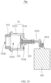
- a pressure generator 30g in the Embodiment VII differs from the pressure generator 30e in the Embodiment V in the following aspects.
- the free end 331 may be in a shape of a flat plate.
- the pressure generator 30g further includes an absorbing member 313 connected to the housing 31.
- An end of the absorbing member 313 defines an adsorbing port 3130.
- the adsorbing port 3130 is communicated to the first opening 3131.
- the periodic alternating positive and negative pressures may also be generated at the adsorbing port 3130.
- the absorbing member 313 is integrally formed with the housing 31. It shall be understood that, in other embodiments, the absorbing member 313 and the housing 31 may be connected by glue or the like. When the absorbing member 313 is arranged in the massager 100', the absorbing member 313 may be integrally formed or separately formed with the flexible sleeve 10.
- the housing 31 includes a first cavity wall 3113 and a second cavity wall 3115.
- the first cavity wall 3113 is extended in the moving direction of the movable member 33 and enclosed to define the first opening 3131.
- the second cavity wall 3115 is disposed at an end of the first cavity wall 3113 away from the first opening 3131.
- the gap 300 is defined between the movable member 33 and the first cavity wall 3113.
- the second cavity wall 3115 is movably extended through the driving end 333.
- the driving end 333 is connected to the movable member 33 and the driving device 35, such that the driving device 35 may drive the driving end 333 to further drive the movable member 33 to reciprocally move within the housing 31.
- the second cavity wall 3115 defines a leaking hole 3116.
- the leaking hole 3116 is extended through the second cavity wall 3115 along the moving direction of the movable member 33.
- the driving device 35 includes a transmission assembly 351 and a motor 353.
- the motor 353 is connected to the driving end 333 through the transmission assembly 351.
- the transmission assembly 351 may be any one of an eccentric transmission structure, a cam, and a rolling ball screw.
- the transmission assembly 351 is the eccentric transmission structure.
- the transmission assembly 351 includes an eccentric member 3511 and a connecting rod 3513 that are transmittably connected to each other.
- the eccentric member 3511 is connected to the motor 353, and the connecting rod 3513 is connected to the driving end 333.
- the adsorbing port 3130 When the pressure generator is operating, the adsorbing port 3130 is placed at a part of the body that needs massage.
- the motor 353 is configured to drive the movable member 33 to reciprocally move in the housing 31 by driving the eccentric member 3511, the connecting rod 3513 and the driving end 333 successively. In this way, the periodic alternating positive and negative pressures may be generated at the adsorbing port 3130, achieving the effect of adsorption and relief.
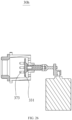
- a difference between a pressure generator 30h in the Embodiment VIII and the pressure generator 30g of the Embodiment VII includes following aspects.
- a plurality of massaging protrusions 373 may be arranged on a side of the movable member 33 facing the first opening 3131. While the movable member 33 is moving reciprocally towards the first opening 3131, the plurality of massaging protrusions 373 may at least partially protrude out of the adsorbing port 3130. In detail, when the movable member 33 moves towards the first opening 3131 to reach a position closest to the first opening 3131, the plurality of massaging protrusions 373 may at least partially protrude out of the adsorbing port 3130. In this way, the plurality of massaging protrusions 373 may massage the body.
- a structure of the driving device 35 is not limited to the structure shown in the fourth and the fifth embodiment.
- the driving device 35 may be an electromagnetic drive member.
- the electromagnetic drive member includes a first magnetic member and a second magnetic member connected to the driving end.
- One of the first magnetic member and the second magnetic member includes wires, and the other of the first magnetic member and the second magnetic member includes a magnet.
- a force between the first magnetic member and the second magnetic member may drive the movable member to move reciprocally.
Landscapes
- Health & Medical Sciences (AREA)
- Epidemiology (AREA)
- Pain & Pain Management (AREA)
- Physical Education & Sports Medicine (AREA)
- Rehabilitation Therapy (AREA)
- Life Sciences & Earth Sciences (AREA)
- Animal Behavior & Ethology (AREA)
- General Health & Medical Sciences (AREA)
- Public Health (AREA)
- Veterinary Medicine (AREA)
- Dermatology (AREA)
- Percussion Or Vibration Massage (AREA)
Description
- The present disclosure relates to the field of massaging devices, and in particular to a pressure generator and a massager.
- D1 (
KR20020059570A - D2 (
KR200167073Y1 - D3 (
DE9309142U1 ) provides a scalp treatment device, which includes a hand-held housing with a treatment head having an air-filled hollow space with a volume which is periodically varied by reciprocation of part of its enclosing wall, under control of battery operated electric drive motor. The application side of the hollow space is fitted with a treatment tool with a number of projecting prongs, at least some of which communicate with the air-filled hollow space and have an opening facing the scalp. - D4 (
DE202017104021U1 ) provides a massage device for massage by means of pressure waves, which includes a housing with a handle section and a massage section, at least one chamber having an opening leading to the outside in the massage section. The chamber has an end wall portion, a first peripheral wall portion and a second peripheral wall portion, the first peripheral wall portion being disposed between the end wall portion and the second peripheral wall portion. and the second peripheral wall portion defines the opening, the end wall portion being at least partially movable, and the massage device includes drive means for imparting a predetermined vibration to the end wall portion, and wherein the first peripheral wall portion is substantially rigid and the second peripheral wall portion is substantially flexible. - With the accelerated pace of life, working pressures on people are increased. After daily working, a person may be tired, various portions of a body may ache. In order to relieve fatigue and soreness, people may take a variety of massagers to massage the body, such as a negative pressure massager. The negative pressure massager may adsorb and relax the skin to relieve the fatigue and soreness, so as to sooth the body and mind. However, the negative pressure massager in the related art may have a complicated structure, and may have a poor adsorption effect.
- Therefore, the massager in the related art needs to be improved to avoid the above defects.
- The invention is defined by the appended claims.
- The present disclosure provides a pressure generator and a massager which can improve suctioning effect thereof.
- One aspect of the present disclosure provides a massager, which includes a flexible sleeve defining an adsorption port, a support shell defining an opening, a pressure generator mounted in the support shell, the pressure generator includes a housing with an opening communicated to the opening of the support shell and a receiving space, and a movable member movably inserted into the receiving space. The pressure generator further includes a driving device including a motor, and a transmission assembly having an eccentric transmission structure including an eccentric member and a connecting rod. The eccentric member connected with the motor, and the connecting rod connected between the eccentric member and the movable member. The flexible sleeve is configured to sleeve around the housing, the adsorption port is arranged in front of the housing and directly communicated with the opening of the housing, and the motor is configured to drive the movable member to reciprocate inside the receiving space without deformation, so as to periodically generate a negative pressure and a positive pressure at the adsorption port.
- In at least one embodiment, the movable member includes a free end arranged in the receiving space, and a sealing ring arranged between the housing and the free end, the sealing ring surrounds the free end and resisting against between the free end and the housing.
- In at least one embodiment, the free end defines a sealing slot configured to receive the sealing ring.
- In at least one embodiment, the sealing ring includes an arc-shaped part and two fixing parts extending from two opposite sides of the arc-shaped part respectively, the two fixing parts are arranged at interval along a moving direction of the free end and extended toward the sealing ring, the arc-shaped part, the two fixing parts and the free end cooperate to define a space, and the arc-shaped part is configured to be deformed into the space.
- In at least one embodiment, the pressure generator further includes a massaging member, the massaging member includes a connecting part connected to a side of the free end facing the opening of the housing, and at least one massaging part arranged on the connecting part away from the free end and configured to partially extend out of the housing through the opening of the housing.
- In at least one embodiment, the movable member is configured to separate the housing into a first chamber communicating with the opening of the housing and a second chamber, and the movable member further includes a unidirectional exhaust structure configured to communicate the first chamber with the second chamber unidirectionally.
- In at least one embodiment, the unidirectional exhaust structure includes at least one exhaust hole running through the free end to communicate the first chamber with the second chamber, and a vent plug arranged on the free end and configured to cover the at least one exhaust hole away from the first chamber.
- In at least one embodiment, the vent plug includes a main part arranged on a side of the free end away from the opening of the housing, and at least one covering part made of elastic material, the at least one covering part is capable of being deformed to cover or open the at least one exhaust hole; or the vent plug includes a main part arranged on a side of the free end away from the opening of the housing and defining at least one through hole communicating with the at least one exhaust hole, and at least one surrounding wall extending away from the main part and surrounding the at least one through hole respectively, the at least one surrounding wall is made of elastic material and capable of being deformed to close or open the at least one through hole.
- In at least one embodiment, the housing includes a rigid part with an opening, and an absorbing member with the opening of the housing arranged on an end of the absorbing member away from the opening of the rigid part, the movable member is arranged inside the rigid part, the absorbing member is connected to the rigid part at the opening of the rigid part and defines an air passage communicating with the opening of the rigid part.
- In at least one embodiment, a gap is defined between the movable member and an inner wall of the housing, the gap is not greater than 0.1mm.
- In at least one embodiment, the pressure generator includes a protective sleeve made of a cushioning material and configured to sleeve an outside of the housing, the protective sleeve defines an opening communicated to the opening of the housing.
- In at least one embodiment, the protective sleeve and the housing are spaced apart from each other to define a sound insulation space.
- In at least one embodiment, the movable member includes a driving end connected to the driving device, and a free end connected to the driving end, and the free end defines a cavity communicated to the receiving space.
- In at least one embodiment, at least one massaging protrusion is arranged on a side of the movable member facing the opening of the housing, the at least one massaging protrusion at least partially extends out of the opening of the housing; and/or the pressure generator includes a heating coil or a semiconductor refrigeration sheet arranged on the housing to adjust temperature at the opening of the housing.
-
-
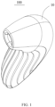
FIG. 1 is a structural schematic view of a massager according to an embodiment of the present disclosure. -
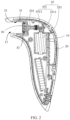
FIG. 2 is a cross-sectional view of the massager as shown inFIG. 1 . -
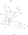
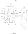
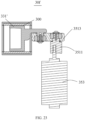
FIG. 3 is an exploded view of a pressure generator as shown inFIG. 1 according to a first embodiment of the present disclosure. -
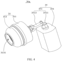
FIG. 4 is a structural schematic view of the pressure generator as shown inFIG. 3 in an assembled state. -
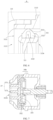
FIG. 5 is a cross-sectional view of the pressure generator as shown inFIG. 4 . -
FIG. 6 is an enlarged view of a portion A as shown inFIG. 5 . -
FIG. 7 is a structural schematic view of a part of a pressure generator as shown inFIG. 1 according to a second embodiment of the present disclosure. -
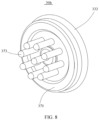
FIG. 8 is a structural schematic view of a massaging member and a sealing ring as shown inFIG. 7 . -
FIG. 9 is a structural schematic view of a pressure generator as shown inFIG. 1 according to a third embodiment of the present disclosure. -
FIG. 10 is a structural schematic view of a vent plug as shown inFIG. 9 . -
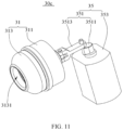
FIG. 11 is a structural schematic view of the pressure generator as shown inFIG. 9 in an assembled state. -
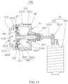
FIG. 12 is a cross-sectional view of the pressure generator as shown inFIG. 11 . -
FIG. 13 is a structural schematic view of a pressure generator according to a fourth embodiment of the present disclosure as shown inFIG. 1 . -
FIG. 14 is a structural schematic view of a vent plug as shown inFIG. 13 . -
FIG. 15 is a bottom plan view of the vent plug as shown inFIG. 14 . -
FIG. 16 is a structural schematic view of the massaging member and the sealing ring of the pressure generator having a unidirectional exhaust structure according to an embodiment of the present disclosure. -
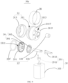
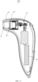
FIG. 17 is a structural schematic view of a massager according to another embodiment of the present disclosure. -
FIG. 18 is a structural schematic view of a pressure generator as shown inFIG. 17 according to a fifth embodiment of the present disclosure. -
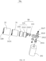
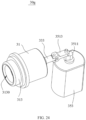
FIG. 19 is an exploded view of the pressure generator as shown inFIG. 18 . -
FIG. 20 is a cross-sectional view of the pressure generator as shown inFIG. 18 . -
FIG. 21 is an enlarged view of a portion B as shown inFIG. 18 according to an embodiment of the present disclosure. -
FIG. 22 is an enlarged view of a portion B as shown inFIG. 18 according to another embodiment of the present disclosure. -
FIG. 23 is a cross-sectional view of a pressure generator as shown inFIG. 17 according to a sixth embodiment of the present disclosure. -
FIG. 24 is a cross-sectional view of a pressure generator as shown inFIG. 17 according to a seventh embodiment of the present disclosure. -
FIG. 25 is a cross-sectional view of the pressure generator as shown inFIG. 24 . -
FIG. 26 is a structural schematic view of a pressure generator as shown inFIG. 17 according to an eighth embodiment of the present disclosure. - Technical solutions in the embodiments of the present disclosure will be clearly and completely described below by referring to the accompanying drawings in the embodiments of the present disclosure. Obviously, the described embodiments are only a part of, but not all of, the embodiments of the present disclosure. All other embodiments obtained by a person of ordinary skill in the art based on the embodiments in the present disclosure and without making creative work shall fall within the scope of the present disclosure.
- As shown in
FIGS. 1 and2 , the present disclosure provides amassager 100. Themassager 100 is configured to massage a body of a user, especially to massage sensitive portions of the body. Themassager 100 may generate a negative pressure to massage and stimulate the sensitive portions. - The massager 1 may include a
support shell 20, apressure generator 30 arranged inside thesupport shell 20, and a battery (not labelled) arranged inside thesupport shell 20. The battery is configured to provide power to thepressure generator 30. Aflexible sleeve 10 may be arranged to sleeve on an outside of thesupport shell 20, and theflexible sleeve 10 is configured to contact the human body. Theflexible sleeve 10 defines anadsorption port 11, and a periphery of a wall of theadsorption port 11 is configured to contact a skin of the human body. Thesupport shell 20 defines afourth opening 21 communicated to theadsorption port 11. Periodic alternating positive and negative pressures generated by thepressure generator 30 may be conducted to the skin through thethird opening 21 to stimulate the skin and achieve a massaging effect. - The
flexible sleeve 10 may be made of a skin-friendly material, such as silicon, to improve the user experience. - The
pressure generator 30 may be implemented by taking specific structures shown in the following embodiments. - Referring to
FIGS. 3 to 6 , apressure generator 30a includes ahousing 31 with afirst opening 3131 and a receivingspace 3132, a movable member 33 (such as a piston) arranged inside thehousing 31, and adriving device 35 configured to drive themovable member 33 to reciprocated move inside thehousing 31 so as to generate a negative pressure at thefirst opening 3131. Themovable member 33 is configured to separate the receivingspace 3132 of thehousing 31 into afirst chamber 3133 and asecond chamber 3134. Thefirst chamber 3133 is communicated with thefirst opening 3131. When in use, thefirst opening 3131 is attached to human body, and the drivingdevice 35 is configured to drive themovable member 33 to move away from thefirst opening 3131 so that a volume of thefirst chamber 3133 is increased and the negative pressure is generated at thefirst opening 3131. Therefore, thefirst opening 3131 can be sucked onto the human body under the negative pressure. - The
housing 31 includes arigid part 311 with asecond opening 3111, and an absorbingmember 313 which is flexible. Themovable member 33 is arranged inside therigid part 311. The absorbingmember 313 is connected to therigid part 311 at thesecond opening 3111. The absorbingmember 313 defines anair passage 3135 communicating with thesecond opening 3111 and thefirst opening 3131. Thefirst opening 3131 is formed at an end of theair passage 3135 away from thesecond opening 3111. - In at least one embodiment, the
rigid part 311 and the absorbingmember 313 are integrally formed. It should be understood that, in at least one another embodiment, therigid part 311 and the absorbingmember 313 are formed independently, and the absorbingmember 313 can be connected to therigid part 311 by any suitable structures, such as adhesive glues. - Referring to
FIG. 5 , therigid part 311 includes afirst chamber wall 3113 extending along a moving direction of themovable member 33 and surrounding thesecond opening 3111, and asecond chamber wall 3115 connected to an end of thefirst chamber wall 3113 away from thesecond opening 3111. A drivingend 333 of themoveable member 33 is configured to movably extend through thesecond chamber wall 3115 and connect themovable member 33 with the drivingdevice 35. The drivingdevice 35 is configured to drive the drivingend 333 to move so as to bring themovable member 33 to reciprocated move inside thehousing 31. - Referring to
FIG. 5 , a self-lubricatingsleeve 335 is arranged between the drivingend 333 and thesecond chamber wall 3115, so that the drivingend 333 may movably extend through thesecond chamber wall 3115, which facilitates reducing a fiction between the drivingend 333 and thesecond chamber wall 3115 when the drivingend 333 moves relative to thesecond chamber wall 3115. - In at least one embodiment, the
second chamber wall 3115 defines at least onevent hole 3117. Referring toFIG. 3 , the number of the at least onevent hole 3117 is multiple. In at least one embodiment, the at least onevent hole 3117 is configured to run through thesecond chamber wall 3115. Through such arrangement, air can be vented outside of thehousing 31 through the at least onevent hole 3117 when themovable member 33 moves away from thefirst opening 3131. Therefore, a resistance of themovable member 33 moving away from thefirst opening 3131 is reduced. Preferably, the at least onevent hole 3117 is configured to run through thesecond chamber wall 3115 along the moving direction of themovable member 33. - The
movable member 33 further includes afree end 331 connected to the drivingend 333, and asealing ring 332 surrounding thefree end 331. The sealingring 332 is configured to resist against between thefree end 331 and the chamber wall of thehousing 31 to ensure a sealing performance. In detail, the sealingring 332 is configured to resist against between thefree end 331 and thefirst chamber wall 3113 of thehousing 31. Therefore, air is prevented from running between thefirst chamber 3133 thesecond chamber 3134. - The driving
end 333 is fixedly connected to thefree end 331, so that a movement of the drivingend 333 can bring themovable member 33 to reciprocated move inside thehousing 31. - In at least one embodiment, the
free end 331 defines asealing slot 3311 on an outer wall thereof, and thesealing ring 332 is at least partially arranged inside thesealing slot 3311. - In at least one embodiment, the sealing
ring 332 includes an arc-shapedpart 3321 and two fixingparts 3323 arranged on two opposite sides of the arc-shapedpart 3321 respectively. The arc-shapedpart 3321 is spaced from thefree end 331. The two fixingparts 3323 are arranged at interval along the moving direction of themovable member 33 and extended toward thesealing slot 3311 and received in thesealing slot 3311. The arc-shapedpart 3321 together with the two fixingparts 3323 and thefree end 331 defines aspace 3325. The arc-shapedpart 3321 can be deformed into thespace 3325 so as to avoid jam during reciprocated moving of themovable member 33. It should be understood that, in at least one embodiment, the sealingring 332 can be an O-shaped sealing ring, such as a traditional rubber sealing ring. - Referring to
FIG. 6 , in at least one embodiment, a center of curvature of the arc-shapedpart 3321 is located at a position facing thespace 3325, which facilitate the deformation of the arc-shapedpart 3321 to move into thespace 3325. - The driving
device 35 includes atransmission assembly 351 and amotor 353. Themotor 353 is configured to connect to the drivingend 333 through thetransmission assembly 351. Thetransmission assembly 351 can be any one of an eccentric transmission structure, a cam and a ball screw. - In at least one embodiment, the
transmission assembly 351 has an eccentric transmission structure and includes aneccentric member 3511 and a connectingrod 3513. Theeccentric member 3511 is connected to themotor 353, and the connectingrod 3513 is hinged with the drivingend 33. When thepressure generator 30a is in use, themotor 353 is configured to drive themovable member 33 to reciprocated move inside thehousing 31 through theeccentric member 3511, the connectingrod 3513, and the drivingend 33. - Referring to
FIGS. 7 and8 , a second embodiment of the present disclosure provides apressure generator 30b. The difference between thepressure generator 30b of the second embodiment and thepressure generator 30a of the first embodiment is that thepressure generator 30b of the second embodiment further includes a massagingmember 37. The massagingmember 37 includes a connectingpart 371 connected to a side of thefree end 331 facing thefirst opening 3131 and at least one massagingprotrusion 373 extending away from the connectingpart 371. The at least one massagingprotrusion 373 is configured to partially extend out of thehousing 31 through thefirst opening 3131. In at least one embodiment, when themovable member 33 moves toward thefirst opening 3131 and moves to a position closest to thefirst opening 3131, the at least one massagingprotrusion 373 at least partially extends out of thehousing 31 so as to massage human body, thus improving user experience. - In at least one embodiment, the massaging
member 37 and thesealing ring 332 are integrally formed. A periphery of the connectingpart 371 is connected with the sealingring 332. It should be understood that, in at least one embodiment, the massagingmember 37 and thesealing ring 332 can be two independent components and the massagingmember 37 can be connected to thefree end 331 of themovable member 33 with any suitable structures, such as adhesive glues. - Referring to
FIGS. 9 to 12 , a third embodiment of the present disclosure provides apressure generator 30c. The difference between thepressure generator 30c of the third embodiment and thepressure generator 30a of the first embodiment is that the movable member 33' ofpressure generator 30c further includes a unidirectional exhaust structure 39 communicating with thefirst chamber 3133 and thesecond chamber 3134. When the movable member 33' moves towards thefirst opening 3131, the unidirectional exhaust structure 39 is configured to communicate thefirst chamber 3133 with thesecond chamber 3134 under the air pressure in thefirst chamber 3133; when the movable member 33' moves away from thefirst opening 3131, the unidirectional exhaust structure 39 is configured to block the communication between thefirst chamber 3133 and thesecond chamber 3134 under the air pressure in thesecond chamber 3134. By setting the unidirectional exhaust structure 39, when the movable member 33' moves away from thefirst opening 3131, negative pressure is generated at thefirst opening 3131; when the movable member 33' moves towards thefirst opening 3131, air in thefirst chamber 3133 can be exhausted to thesecond chamber 3134 through the unidirectional exhaust structure 39, and thesecond chamber 3134 is communicated with the outside. Thus, the resistance during the movement of the movable member 33' can be reduced. - The unidirectional exhaust structure 39 includes at least one
exhaust hole 391 running through thefree end 331 of the movable member 33' to communicate thefirst chamber 3133 with thesecond chamber 3134, and avent plug 393 arranged on a side of thefree end 331 away from thefirst chamber 3133 and configured to cover the at least oneexhaust hole 391. When the movable member 33' moves towards thefirst opening 3131, thevent plug 393 is configured to move to open theexhaust hole 391 so that thefirst chamber 3133 communicates with thesecond chamber 3134 through theexhaust hole 391 under the air pressure in thefirst chamber 3133. When the movable member 33' moves away from thefirst opening 3131, thevent plug 393 is configured to block the communication between thefirst chamber 3133 and thesecond chamber 3134 under the air pressure in thesecond chamber 3134. - Referring to
FIGS. 10 and12 , thevent plug 393 is an annular sheet. In at least one embodiment, thevent plug 393 can be deformed. For example, thevent plug 393 can be made of silicon material to make thevent plug 393 flexible and soft. In detail, referring toFIG. 10 , thevent plug 393 includes amain part 3931 arranged on the side of thefree end 331 of the movable member 33' away from thefirst opening 3131 and at least one coveringpart 3933 configured to cover the at least oneexhaust hole 391. Themain part 3931 defines at least one throughhole 3932. Thecovering part 3933 is extended from themain part 3931 into the at least one throughhole 3932 respectively. In at least one embodiment, thecovering part 3933 can move relative to themain part 3931. - When the movable member 33' moves away from the
first opening 3131, the volume of thefirst chamber 3133 is increased to decrease the air pressure in the first chamber 3133 (a difference between the air pressure in thefirst chamber 3133 and the air pressure in thesecond chamber 3134 is not sufficient to prevent a deformation of the covering part 3933), therefore, the negative pressure is generated at thefirst opening 3131 to generate a suction force applied on human body. At the same time, thecovering part 3933 covers the at least oneexhaust hole 391 to block the communication between thefirst chamber 3133 and thesecond chamber 3134 under the negative pressure. With the volume of thefirst chamber 3133 getting bigger, the negative pressure getting bigger, which forces the coveringpart 3933 to remain covering the at least oneexhaust hole 391 to keep blocking the communication between thefirst chamber 3133 and thesecond chamber 3134. Therefore, thefirst opening 3131 remains at a suction state. - When the movable member 33' moves towards the
first opening 3131, the volume of thefirst chamber 3133 is decreased to decrease the negative pressure. The movable member 33' compresses air in thefirst chamber 3133 to increase the air pressure in thefirst chamber 3133. When a difference between the air pressure in thefirst chamber 3133 and the air pressure in thesecond chamber 3134 is greater enough to deform thecovering part 3933 to open the at least oneexhaust hole 391, air is vented from thefirst chamber 3133 to thesecond chamber 3134 to reduce the movement resistance of the movable member 33'. - In at least one embodiment, the
main part 3931 can be connected to thefree end 331 of the movable member 33' by adhesive glues. - In at least one embodiment, referring to
FIGS. 9 and10 , the number of the at least oneexhaust hole 391 is multiple. Correspondingly, the number of the at least one throughhole 3932 and the number of the at least one coveringpart 3933 are multiple. - In at least one embodiment, referring to
FIGS. 12 and13 , aheating coil 38 or asemiconductor refrigeration sheet 38 is arranged on therigid part 311. In detail, theheating coil 38 or thesemiconductor refrigeration sheet 38 are arranged on an outer side of thefirst chamber wall 3113. In at least one embodiment, thesemiconductor refrigeration sheet 38 includes a hot end and a cold end opposite to the hot end. The hot end or the cold end can be attached to thefirst chamber wall 3113 so as to adjust a temperature of the absorbingmember 313, thereby improving user's experiences. It should be understood that, in at least one embodiment, thesemiconductor refrigeration sheet 38 can be replaced with theheating coil 38. - The sealing ring 332' can be a general O-shaped sealing ring, such as a rubber sealing ring. It should be understood that, in at least one embodiment, the sealing ring 332' can be the sealing
ring 332 described in the first embodiment. That is, the sealing ring 332' can include the arc-shapedpart 3321 and two fixingparts 3323 arranged two opposite sides of the arc-shapedpart 3321 respectively. The two fixingparts 3323 are arranged at interval along the moving direction of the movable member and extended toward sealingslot 3311 and received in thesealing slot 3311 and received in thesealing slot 3311. The arc-shapedpart 3321 together with the two fixingparts 3323 and thefree end 331 defines aspace 3325. The arc-shapedpart 3321 can be deformed into thespace 3325. - Referring to
FIGS. 13 to 15 , a fourth embodiment of the present disclosure provides apressure generator 30d. The difference between thepressure generator 30d of the fourth embodiment and thepressure generator 30c of the third embodiment is that a structure of the vent plug 393' is different from that of thevent plug 393. The vent plug 393' includes a main part 3931' arranged on the side of thefree end 331 of the movable member 33' away from thefirst opening 3131 and at least one surroundingwall 3935 extending away from the main part 3931'. The main part 3931' defines at least one through hole 3932' corresponding to the at least oneexhaust hole 391. The through holes 3932' is configured to communicate with the at least oneexhaust hole 391. The at least one surroundingwall 3935 is configured to surround the at least one through hole 3932' respectively, and extend toward thesecond chamber 3134. Each of the at least one surroundingwall 3935 defines anair channel 3937 communicating with a corresponding through hole 3932'. The surroundingwall 3935 is made of elastic material and configured to be deformed to open or close (or substantially close) theair channel 3937. - When the
movable member 33" moves away from thefirst opening 3131, the volume of thefirst chamber 3133 is increased to decrease the air pressure in the first chamber 3133 (a difference between the air pressure in thefirst chamber 3133 and the air pressure in thesecond chamber 3134 is not sufficient to prevent a deformation of the surrounding wall 3935), therefore, negative pressure is generated at thefirst opening 3131 to generate a suction force applied on human body. At the same time, the surroundingwall 3935 closes to block the communication between thefirst chamber 3133 and thesecond chamber 3134 under the negative pressure. With the volume of thefirst chamber 3133 getting bigger, the negative pressure getting bigger, which forces the surroundingwall 3935 to remain blocking the communication between thefirst chamber 3133 and thesecond chamber 3134. Therefore, thefirst opening 3131 remains at the suction state. - When the
movable member 33" moves toward thefirst opening 3131, the volume of thefirst chamber 3133 is decreased to decrease the negative pressure. Themoveable member 33 compresses air in thefirst chamber 3133 to increase the air pressure in thefirst chamber 3133. When a difference between the air pressure in thefirst chamber 3133 and the air pressure in the second chamber 3134 (the air pressure in thefirst chamber 3133 is greater than the air pressure in the second chamber 3134) is greater enough to make the surroundingwall 3935 deform to open theair channel 3937, the at least oneair channel 3937 is communicated thefirst chamber 3133 through the at least one throughholes 3932 and the at least oneexhaust hole 391 with thesecond chamber 3134, therefore, air can be vented from thefirst chamber 3133 to thesecond chamber 3134 to reduce the movement resistance of themovable member 33". - It should be understood that, the unidirectional exhaust structure of the present disclosure is not limited to the unidirectional exhaust structure 39 described in the third embodiment and the fourth embodiment. For example, the unidirectional exhaust structure 39 can be a one-way valve extending through the
free end 331. Thevent plug 393, 393' described in the third embodiment and the fourth embodiment can be a flat plate structure made of rigid material, and the vent plug can be connected to thefree end 331 through a spring. When the air pressure in thefirst chamber 3133 is greater enough to make the spring deform to open theexhaust hole 391. When themovable member 33 moves away from thefirst opening 3131, the volume of thefirst chamber 3133 gets bigger to decrease the air pressure in thefirst chamber 3133, the vent plug 35 blocks theexhaust hole 391 to block the communication between thefirst chamber 3133 and thesecond chamber 3134. Along with the volume of thefirst chamber 3133 gets bigger, the negative pressure gets bigger, which forces thevent plug 35 to remain blocking theexhaust hole 391. - The negative pressure generator with the unidirectional exhaust structure is not limited to the negative pressure generator shown in the third and fourth embodiments. Referring to
FIG. 16 , the negative pressure generator with the unidirectional exhaust structure can further includes the massagingmember 37 as shown inFIG. 8 . The massagingmember 37 includes the connectingpart 371 connected to a side of thefree end 331 of themovable member 33 facing thefirst opening 3131 and the massagingprotrusions 373 extending away from the connectingpart 371. The massagingprotrusions 373 is configured to be capable of at least partially extending out of thehousing 31 through thefirst opening 3131. In order to make thefirst chamber 3133 and thesecond chamber 3134 communicate with each other, the connectingpart 371 defines at least oneair hole 3711 communicating with the at least oneexhaust hole 391. Additionally, referring toFIG. 16 , the massagingmember 37 can be integrally formed with the sealingring 332 with an outer edge of the connectingpart 371 connected with the sealingring 332. - It should be understood that, the driving device is not limited to the driving
device 35 shown in the first to fourth embodiments. For example, the driving device can be an electromagnetic driver. The electromagnetic driver includes a first magnetic component and a second magnetic component connected to the transmission member. One of the first magnetic component and the second magnetic component is a coil, and the other one of the first magnetic component and the second magnetic component is a magnet. When the coil is energized, interaction force between the first magnetic component and the second magnetic component can drive the movable member to reciprocated move. - The magnet can be a permanent magnet or an electromagnet.
- As shown in
FIG. 17 , the present disclosure provides a massager 100'. The massager 100' is configured to massage a body of a user, especially to massage sensitive portions of the body. The massager 100' may generate a negative pressure to massage and stimulate the sensitive portions. - The massager 100' may include a
support shell 20, apressure generator 30 arranged inside thesupport shell 20, and abattery 40 arranged inside thesupport shell 20. Thebattery 40 is configured to provide power to thepressure generator 30. Aflexible sleeve 10 may be arranged to sleeve an outside of thesupport shell 20, and theflexible sleeve 10 is configured to contact the human body. Theflexible sleeve 10 defines anadsorption port 11, and a periphery of a wall of theadsorption port 11 is configured to contact a skin of the user. Thesupport shell 20 defines a third opening 200 communicated to theadsorption port 11. Periodic alternating positive and negative pressures generated by thepressure generator 30 may be conducted to the skin through the third opening 200 to stimulate the skin and achieve a massaging effect. - The
flexible sleeve 10 may be made of a skin-friendly material, such as silicon, to improve the user experience. - The
pressure generator 30 may be implemented by taking specific structures shown in the following embodiments. - As shown in
FIGS. 18 to 22 , a fifth embodiment of the present disclosure provides apressure generator 30e. Thepressure generator 30e includes ahousing 31 defining a receivingspace 3132, amovable member 33 movably extending into the receivingspace 3132, and adriving device 35. The drivingdevice 35 is configured to drive themovable member 33 to move along the receivingspace 3132 reciprocally and linearly. Thehousing 31 defines afirst opening 3131 communicated to the receivingspace 3132. Agap 300 is defined between themovable member 33 and an inner wall of thehousing 31. - In detail, the
movable member 33 includes afree end 331 and adriving end 333. Acavity 3310 is defined in thefree end 331. Thefree end 331 includes abottom wall 3315 connected to the drivingend 333 and aside wall 3313 extending from thebottom wall 3315 toward thefirst opening 3131. Thebottom wall 3315 and theside wall 3313 cooperatively define thecavity 3310. Thecavity 3310 is communicated to the receivingspace 3132. Thecavity 3310 allows a volume of the receivingspace 3132 to be increased so that thepressure generator 30e has a large pressure variation range and a large pressure variation space. At the same time, thecavity 3310 may increase a contact area between themovable member 33 and air in the receivingspace 3132, such that themovable member 33 may be subjected to a uniform force while moving, and themovable member 33 may move stably. The drivingend 333 includes a transmitting element (not labelled) extended along the moving direction of the moveablymember 33. - The
free end 331 further includes asleeve ring 334 sleeving theside wall 3313. Thesleeve ring 334 is made of a metal, preferably made of aluminum alloy and the like. In the present embodiment, thegap 300 is defined between thesleeve ring 334 and the inner wall of thehousing 31. As desired, an outer diameter of thebottom wall 3315 is greater than an outer diameter of theside wall 3313, thereby forming a limiting stage (not labelled) to position thesleeve ring 334. In the present embodiment, themovable member 33 includes a piston. - In the present embodiment, the
pressure generator 30e further includes aprotective sleeve 32. Theprotective sleeve 32 is made of a cushioning material and sleeved an outside of thehousing 31. Theprotective sleeve 32 defines athird opening 320 communicated to thefirst opening 3131. Theprotective sleeve 32 is made of a cushioning material, such as silicone and the like. As shown inFIG. 17 , theprotective sleeve 32 is disposed between thesupport shell 20 and thehousing 31. By arranging theprotective sleeve 32, transmission of vibration to the outside may be reduced, and on the other hand, transmission of noise, which is generated due to themovable member 33 moving while themovable member 33 contacts thehousing 31, to the outside may be reduced, such that noise may be reduced. - Only when the
gap 300 is not greater than 0.1mm, a dynamic pressure may be generated at thethird opening 320 and thefirst opening 3131, i.e., the negative pressure may be generated at thethird opening 320 and thefirst opening 3131. By defining thegap 300 to be smaller, a larger noise may be prevented while using the massager 100', achieving a noise reduction. In use, the drivingdevice 35 may be arranged to allow the movable member 33 (such as a piston) to move along a length direction in thehousing 31 reciprocally. When theadsorption port 11 of the massager 100' is attached to the skin, thethird opening 320 is covered. Themovable member 33 moving reciprocally may change a volume of the receivingspace 3132 defined by thehousing 31. In this way, an internal air pressure is dynamically changed, even when the receiving space defined by thehousing 31 generates the alternating positive and negative pressures. Preferably, thegap 300 is not greater than 0.05 mm. - In the present embodiment, as shown in
FIG. 20 , ablock 321 is arranged at each of two ends of theprotective sleeve 32, and theblock 321 is extended toward the receivingspace 3132. Twoblocks 321 define a receiving cavity of thehousing 31. The outside of thehousing 31 is sleeved by theprotective sleeve 32 for wrapping, which can further reduce noise. Theblock 321 may be a convex block, and a plurality ofblocks 321 may be spaced apart from each other and disposed between the two ends of theprotective sleeve 32. Alternatively, theblock 321 may be a ring-shaped wall, and twoblocks 321 may be disposed at the two ends of theprotective sleeve 32 respectively. - As shown in
FIG. 22 , theprotective sleeve 32 and thehousing 31 may be spaced apart from each other to define asound insulation space 310. Thesound insulation space 310 prevents the noise, which is generated by the reciprocating movement of themovable member 33, from transmitting to the outside, thus further reducing the noise. As needed, thesound insulation space 310 may preferably be a vacuum, which has a better effect to reduce the noise. - The driving
device 35 includes atransmission assembly 351 and amotor 353. Thetransmission assembly 351 includes aneccentric member 3511 arranged on a shaft of themotor 353 and a connectingrod 3513. Theeccentric member 3511 is movably connected to the drivingend 333 through the connectingrod 3513. Abearing 3515 may be disposed between the connectingrod 3513 and the drivingend 333, and anotherbearing 3515 may be disposed between the connectingrod 3513 and theeccentric member 3511. Thebearing 3515 is fixed to theeccentric member 3511 through ascrew 3517 to allow the connectingrod 3513 and theeccentric part 32 to rotate stably. The anotherbearing 3515 is fixed to a fixed protrusion on the drivingend 333 through anotherscrew 3517 to allow the connectingrod 3513 and the drivingend 333 to rotate stably. - Another embodiment of the present disclosure further provides a
pressure generator 30f. Referring toFIG. 23 , thepressure generator 30f differs from thepressure generator 30e in the above embodiment only in that: thesleeve ring 334 and theside wall 3313 of themovable member 33 are configured as a one-piece structure. The one-piece structure is plastic. Preferably, thesleeve ring 334 and theside wall 3313 are formed as one piece by injection molding. Other structures of thepressure generator 30f are the same as those in the fifth embodiment, and will not be repeated. - As shown in
FIGS. 24 and25 , apressure generator 30g in the Embodiment VII differs from thepressure generator 30e in the Embodiment V in the following aspects. - As shown in
FIG. 25 , thefree end 331 may be in a shape of a flat plate. - In the present embodiment, the
pressure generator 30g further includes an absorbingmember 313 connected to thehousing 31. An end of the absorbingmember 313 defines an adsorbingport 3130. The adsorbingport 3130 is communicated to thefirst opening 3131. The periodic alternating positive and negative pressures may also be generated at the adsorbingport 3130. - In the present embodiment, the absorbing
member 313 is integrally formed with thehousing 31. It shall be understood that, in other embodiments, the absorbingmember 313 and thehousing 31 may be connected by glue or the like. When the absorbingmember 313 is arranged in the massager 100', the absorbingmember 313 may be integrally formed or separately formed with theflexible sleeve 10. - The
housing 31 includes afirst cavity wall 3113 and asecond cavity wall 3115. Thefirst cavity wall 3113 is extended in the moving direction of themovable member 33 and enclosed to define thefirst opening 3131. Thesecond cavity wall 3115 is disposed at an end of thefirst cavity wall 3113 away from thefirst opening 3131. Thegap 300 is defined between themovable member 33 and thefirst cavity wall 3113. Thesecond cavity wall 3115 is movably extended through the drivingend 333. The drivingend 333 is connected to themovable member 33 and the drivingdevice 35, such that the drivingdevice 35 may drive the drivingend 333 to further drive themovable member 33 to reciprocally move within thehousing 31. - In the present embodiment, the
second cavity wall 3115 defines aleaking hole 3116. The leakinghole 3116 is extended through thesecond cavity wall 3115 along the moving direction of themovable member 33. - The driving
device 35 includes atransmission assembly 351 and amotor 353. Themotor 353 is connected to the drivingend 333 through thetransmission assembly 351. Thetransmission assembly 351 may be any one of an eccentric transmission structure, a cam, and a rolling ball screw. - In the present embodiment, the
transmission assembly 351 is the eccentric transmission structure. Thetransmission assembly 351 includes aneccentric member 3511 and a connectingrod 3513 that are transmittably connected to each other. Theeccentric member 3511 is connected to themotor 353, and the connectingrod 3513 is connected to the drivingend 333. - When the pressure generator is operating, the adsorbing
port 3130 is placed at a part of the body that needs massage. Themotor 353 is configured to drive themovable member 33 to reciprocally move in thehousing 31 by driving theeccentric member 3511, the connectingrod 3513 and the drivingend 333 successively. In this way, the periodic alternating positive and negative pressures may be generated at the adsorbingport 3130, achieving the effect of adsorption and relief. - As shown in
FIG. 26 , a difference between apressure generator 30h in the Embodiment VIII and thepressure generator 30g of the Embodiment VII includes following aspects. - In the fourth embodiment, a plurality of massaging
protrusions 373 may be arranged on a side of themovable member 33 facing thefirst opening 3131. While themovable member 33 is moving reciprocally towards thefirst opening 3131, the plurality of massagingprotrusions 373 may at least partially protrude out of the adsorbingport 3130. In detail, when themovable member 33 moves towards thefirst opening 3131 to reach a position closest to thefirst opening 3131, the plurality of massagingprotrusions 373 may at least partially protrude out of the adsorbingport 3130. In this way, the plurality of massagingprotrusions 373 may massage the body. - To be noted that, a structure of the driving
device 35 is not limited to the structure shown in the fourth and the fifth embodiment. For example, the drivingdevice 35 may be an electromagnetic drive member. The electromagnetic drive member includes a first magnetic member and a second magnetic member connected to the driving end. One of the first magnetic member and the second magnetic member includes wires, and the other of the first magnetic member and the second magnetic member includes a magnet. When the wire is conducted, a force between the first magnetic member and the second magnetic member may drive the movable member to move reciprocally.
Claims (14)
- A massager (100), comprising:a flexible sleeve (10), defining an adsorption port (11);a support shell (20), defining an opening (21);a pressure generator (30), mounted in the support shell (20), the pressure generator (30) comprises a housing (31) with an opening (3131) communicated to the opening (21) of the support shell and a receiving space (3132), and a movable member (33) movably inserted into the receiving space (3132), characterized in that, the pressure generator (30) further comprises:
a driving device (35), comprising a motor (353), a transmission assembly having an eccentric transmission structure including an eccentric member (3511) and a connecting rod (3512), the eccentric member (3511) connected with the motor (353), and the connecting rod (3513) connected between the eccentric member (3511) and the movable member (33);the flexible sleeve (10) is configured to sleeve around the housing (31), the adsorption port (11) is arranged in front of the housing (31) and directly communicated with the opening (3131) of the housing, and the motor (353) is configured to drive the movable member (33) to reciprocate inside the receiving space (3132) without deformation, so as to periodically generate a negative pressure and a positive pressure at the adsorption port (11). - The massager (100) according to claim 1, wherein the movable member (33) comprises:a free end (331) arranged in the receiving space (3132); anda sealing ring (332) arranged between the housing (31) and the free end (331), the sealing ring (332) surrounding the free end (331) and resisting against between the free end (331) and the housing (31).
- The massager (100) according to claim 2, wherein the free end (331) defines a sealing slot (3311) configured to receive the sealing ring (332).
- The massager (100) according to claim 3, wherein the sealing ring (332) comprises:an arc-shaped part (3321); andtwo fixing parts (3323) extending from two opposite sides of the arc-shaped part (3321) respectively, the two fixing parts (3323) being arranged at interval along a moving direction of the free end (331) and extended toward the sealing ring (332), the arc-shaped part (3321), the two fixing parts (3323) and the free end (331) cooperating to define a space (3325), and the arc-shaped part (3321) being configured to be deformed into the space (3325).
- The massager (100) according to claim 2, wherein the pressure generator further comprising a massaging member (37), the massaging member (37) comprising:a connecting part (371) connected to a side of the free end (331) facing the opening (3131); andat least one massaging part (373) arranged on the connecting part (371) away from the free end (331) and configured to partially extend out of the housing (31) through the opening (3131).
- The massager (100) according to claim 2, wherein, the movable member (33) is configured to separate the housing (31) into a first chamber (3313) communicating with the opening (3131) of the housing and a second chamber (3134); and
the movable member (33) further comprises a unidirectional exhaust structure (39) configured to communicate the first chamber (3313) with the second chamber (3134) unidirectionally. - The massager (100) according to claim 6, wherein the unidirectional exhaust structure (39) comprises:at least one exhaust hole (391) running through the free end (331) to communicate the first chamber (3313) with the second chamber (3134); anda vent plug (393) arranged on the free end (331) and configured to cover the at least one exhaust hole (391) away from the first chamber (3313).
- The massager (100) according to claim 7, wherein
the vent plug (393) comprises:a main part (3931) arranged on a side of the free end (331) away from the opening (3131); andat least one covering part (3933) made of elastic material, the at least one covering part (3933) being capable of being deformed to cover or open the at least one exhaust hole (391); orthe vent plug (393) comprises:a main part (3931) arranged on a side of the free end (331) away from the opening (3131) and defining at least one through hole (3932) communicating with the at least one exhaust hole (391); andat least one surrounding wall (3935) extending away from the main part (3931) and surrounding the at least one through hole (3932) respectively, the at least one surrounding wall (3935) being made of elastic material and capable of being deformed to close or open the at least one through hole (3932). - The massager (100) according to claim 2, wherein the housing (31) comprises:a rigid part (311) with an opening (3111), the movable member (33) being arranged inside the rigid part (311); andan absorbing member (313) with the opening (3131) arranged on an end of the absorbing member (313) away from the opening (3111), the absorbing member (313) being connected to the rigid part (311) at the opening (3111) and defining an air passage (3135) communicating with the opening (3111).
- The massager (100) according to claim 1, wherein a gap (300) is defined between the movable member (33) and an inner wall of the housing (31), the gap (300) being not greater than 0.1mm.
- The massager (100) according to claim 10, wherein further comprising a protective sleeve (32) made of a cushioning material and configured to sleeve an outside of the housing (31), the protective sleeve (32) defining an opening (320) communicated to the opening (3131).
- The massager (100) according to claim 11, wherein the protective sleeve (32) and the housing (31) are spaced apart from each other to define a sound insulation space (310).
- The massager (100) according to claim 10, wherein the movable member (33) comprises:a driving end (333) connected to the driving device (35); anda free end (331) connected to the driving end (333), and the free end (331) defining a cavity (3310) communicated to the receiving space (3132).
- The massager (100) according to claim 1, wherein at least one massaging protrusion (373) is arranged on a side of the movable member (33) facing the opening (3131) of the housing,the at least one massaging protrusion (373) at least partially extending out of the opening (3131) of the housing;and/or the pressure generator (30) comprises a heating coil (38) or a semiconductor refrigeration sheet (38) arranged on the housing (31) to adjust temperature at the opening (3131) of the housing.
Applications Claiming Priority (3)
| Application Number | Priority Date | Filing Date | Title |
|---|---|---|---|
| CN202121128803.7U CN215961014U (en) | 2021-05-22 | 2021-05-22 | Negative pressure generator and negative pressure massager |
| CN202110715294.6A CN113274268B (en) | 2021-06-26 | 2021-06-26 | Negative pressure generator and negative pressure massager |
| CN202210018720.5A CN114246782A (en) | 2022-01-08 | 2022-01-08 | Dynamic pressure generating device and massager |
Publications (2)
| Publication Number | Publication Date |
|---|---|
| EP4091595A1 EP4091595A1 (en) | 2022-11-23 |
| EP4091595B1 true EP4091595B1 (en) | 2025-04-23 |
Family
ID=80447459
Family Applications (1)
| Application Number | Title | Priority Date | Filing Date |
|---|---|---|---|
| EP22158147.3A Active EP4091595B1 (en) | 2021-05-22 | 2022-02-23 | Pressure generator and massager |
Country Status (2)
| Country | Link |
|---|---|
| EP (1) | EP4091595B1 (en) |
| ES (1) | ES3032994T3 (en) |
Citations (7)
| Publication number | Priority date | Publication date | Assignee | Title |
|---|---|---|---|---|
| US1882040A (en) | 1930-03-08 | 1932-10-11 | William A Roehm | Suction-massage apparatus |
| FR2746639A1 (en) | 1996-04-01 | 1997-10-03 | Grea Alain | Localised skin massaging instrument |
| KR20020059570A (en) | 2001-11-30 | 2002-07-13 | 김의택 | Air skin stimulator |
| US20080304984A1 (en) | 2007-06-08 | 2008-12-11 | Man-Yan Chan | Therapeutic device |
| JP2011083423A (en) | 2009-10-15 | 2011-04-28 | Panasonic Electric Works Co Ltd | Stimulation imparting device for living body |
| DE202012005414U1 (en) | 2012-06-01 | 2012-06-21 | Frank Bierschenk | Portable electrical device for intimate stimulation and connective tissue massage |
| US10792214B2 (en) | 2017-07-12 | 2020-10-06 | LELO Inc. | Stimulation devices and methods of use |
Family Cites Families (3)
| Publication number | Priority date | Publication date | Assignee | Title |
|---|---|---|---|---|
| DE4320329C1 (en) * | 1993-06-18 | 1994-07-14 | D & P Cosmetics Ag Adliswil | Hand-held scalp treatment device |
| KR200167073Y1 (en) * | 1999-08-02 | 2000-02-15 | 유태우 | Massager for cupping glasses |
| DE202017104021U1 (en) * | 2017-07-05 | 2018-10-09 | Fun Factory Gmbh | Massage device for pressure wave massage |
-
2022
- 2022-02-23 ES ES22158147T patent/ES3032994T3/en active Active
- 2022-02-23 EP EP22158147.3A patent/EP4091595B1/en active Active
Patent Citations (8)
| Publication number | Priority date | Publication date | Assignee | Title |
|---|---|---|---|---|
| US1882040A (en) | 1930-03-08 | 1932-10-11 | William A Roehm | Suction-massage apparatus |
| FR2746639A1 (en) | 1996-04-01 | 1997-10-03 | Grea Alain | Localised skin massaging instrument |
| KR20020059570A (en) | 2001-11-30 | 2002-07-13 | 김의택 | Air skin stimulator |
| US20080304984A1 (en) | 2007-06-08 | 2008-12-11 | Man-Yan Chan | Therapeutic device |
| JP2011083423A (en) | 2009-10-15 | 2011-04-28 | Panasonic Electric Works Co Ltd | Stimulation imparting device for living body |
| DE202012005414U1 (en) | 2012-06-01 | 2012-06-21 | Frank Bierschenk | Portable electrical device for intimate stimulation and connective tissue massage |
| WO2013178223A2 (en) | 2012-06-01 | 2013-12-05 | Frank Bierschenk | Massage device |
| US10792214B2 (en) | 2017-07-12 | 2020-10-06 | LELO Inc. | Stimulation devices and methods of use |
Non-Patent Citations (4)
| Title |
|---|
| D1a - Kopie von Fig. 3 der D1 |
| D2a - Stellungnahme von Prof. Rung |
| D5a - Stellungnahme von Prof. Rung |
| D5b - Ergänzende Stellungnahme von Prof. Rung |
Also Published As
| Publication number | Publication date |
|---|---|
| EP4091595A1 (en) | 2022-11-23 |
| ES3032994T3 (en) | 2025-07-29 |
Similar Documents
| Publication | Publication Date | Title |
|---|---|---|
| CN113274268B (en) | Negative pressure generator and negative pressure massager | |
| US11452665B1 (en) | Pressure generator and massager having pressure generator | |
| US11806306B1 (en) | Surround pinch-kneading massager | |
| US20210307998A1 (en) | Handheld massage device | |
| US20240122786A1 (en) | Massage device | |
| US11951070B2 (en) | Massager | |
| JP2013543782A (en) | Device for massaging the human or animal body | |
| US20230390144A1 (en) | Massaging device | |
| US20250186299A1 (en) | Massager | |
| CN112155985A (en) | Fascia gun | |
| EP4091595B1 (en) | Pressure generator and massager | |
| JPH08294414A (en) | Sucking cup | |
| WO2024152549A1 (en) | Airwave massage device | |
| EP3871647A1 (en) | Massaging device with negative pressure cavity | |
| CN217744990U (en) | Negative pressure generator and negative pressure massager | |
| CN219271509U (en) | Air wave massage device | |
| CN2493204Y (en) | Eye massager | |
| CN213666080U (en) | Massage device | |
| US20250186293A1 (en) | Massage Device | |
| CN216148523U (en) | Sucking massager | |
| CN213219006U (en) | a fascia gun | |
| CN213641978U (en) | Negative pressure physiotherapy cupping moxibustion | |
| CN213666628U (en) | Sucking massager adopting cylindrical cam transmission | |
| WO2022267114A1 (en) | Negative pressure generator and negative pressure massager | |
| US12144781B1 (en) | Massage device |
Legal Events
| Date | Code | Title | Description |
|---|---|---|---|
| PUAI | Public reference made under article 153(3) epc to a published international application that has entered the european phase |
Free format text: ORIGINAL CODE: 0009012 |
|
| STAA | Information on the status of an ep patent application or granted ep patent |
Free format text: STATUS: REQUEST FOR EXAMINATION WAS MADE |
|
| 17P | Request for examination filed |
Effective date: 20220318 |
|
| AK | Designated contracting states |
Kind code of ref document: A1 Designated state(s): AL AT BE BG CH CY CZ DE DK EE ES FI FR GB GR HR HU IE IS IT LI LT LU LV MC MK MT NL NO PL PT RO RS SE SI SK SM TR |
|
| STAA | Information on the status of an ep patent application or granted ep patent |
Free format text: STATUS: EXAMINATION IS IN PROGRESS |
|
| 17Q | First examination report despatched |
Effective date: 20240523 |
|
| GRAP | Despatch of communication of intention to grant a patent |
Free format text: ORIGINAL CODE: EPIDOSNIGR1 |
|
| STAA | Information on the status of an ep patent application or granted ep patent |
Free format text: STATUS: GRANT OF PATENT IS INTENDED |
|
| INTG | Intention to grant announced |
Effective date: 20241212 |
|
| RAP3 | Party data changed (applicant data changed or rights of an application transferred) |
Owner name: SHENZHEN SVAKOM TECHNOLOGY CO., LTD |
|
| GRAS | Grant fee paid |
Free format text: ORIGINAL CODE: EPIDOSNIGR3 |
|
| GRAA | (expected) grant |
Free format text: ORIGINAL CODE: 0009210 |
|
| STAA | Information on the status of an ep patent application or granted ep patent |
Free format text: STATUS: THE PATENT HAS BEEN GRANTED |
|
| AK | Designated contracting states |
Kind code of ref document: B1 Designated state(s): AL AT BE BG CH CY CZ DE DK EE ES FI FR GB GR HR HU IE IS IT LI LT LU LV MC MK MT NL NO PL PT RO RS SE SI SK SM TR |
|
| REG | Reference to a national code |
Ref country code: GB Ref legal event code: FG4D |
|
| REG | Reference to a national code |
Ref country code: CH Ref legal event code: EP |
|
| REG | Reference to a national code |
Ref country code: DE Ref legal event code: R096 Ref document number: 602022013374 Country of ref document: DE |
|
| REG | Reference to a national code |
Ref country code: IE Ref legal event code: FG4D |
|
| REG | Reference to a national code |
Ref country code: NL Ref legal event code: FP |
|
| REG | Reference to a national code |
Ref country code: ES Ref legal event code: FG2A Ref document number: 3032994 Country of ref document: ES Kind code of ref document: T3 Effective date: 20250729 |
|
| REG | Reference to a national code |
Ref country code: AT Ref legal event code: MK05 Ref document number: 1787117 Country of ref document: AT Kind code of ref document: T Effective date: 20250423 |
|
| PG25 | Lapsed in a contracting state [announced via postgrant information from national office to epo] |
Ref country code: FI Free format text: LAPSE BECAUSE OF FAILURE TO SUBMIT A TRANSLATION OF THE DESCRIPTION OR TO PAY THE FEE WITHIN THE PRESCRIBED TIME-LIMIT Effective date: 20250423 Ref country code: PT Free format text: LAPSE BECAUSE OF FAILURE TO SUBMIT A TRANSLATION OF THE DESCRIPTION OR TO PAY THE FEE WITHIN THE PRESCRIBED TIME-LIMIT Effective date: 20250825 |
|
| REG | Reference to a national code |
Ref country code: LT Ref legal event code: MG9D |
|
| PG25 | Lapsed in a contracting state [announced via postgrant information from national office to epo] |
Ref country code: GR Free format text: LAPSE BECAUSE OF FAILURE TO SUBMIT A TRANSLATION OF THE DESCRIPTION OR TO PAY THE FEE WITHIN THE PRESCRIBED TIME-LIMIT Effective date: 20250724 Ref country code: NO Free format text: LAPSE BECAUSE OF FAILURE TO SUBMIT A TRANSLATION OF THE DESCRIPTION OR TO PAY THE FEE WITHIN THE PRESCRIBED TIME-LIMIT Effective date: 20250723 |
|
| PG25 | Lapsed in a contracting state [announced via postgrant information from national office to epo] |
Ref country code: PL Free format text: LAPSE BECAUSE OF FAILURE TO SUBMIT A TRANSLATION OF THE DESCRIPTION OR TO PAY THE FEE WITHIN THE PRESCRIBED TIME-LIMIT Effective date: 20250423 |
|
| PG25 | Lapsed in a contracting state [announced via postgrant information from national office to epo] |
Ref country code: BG Free format text: LAPSE BECAUSE OF FAILURE TO SUBMIT A TRANSLATION OF THE DESCRIPTION OR TO PAY THE FEE WITHIN THE PRESCRIBED TIME-LIMIT Effective date: 20250423 |
|
| PG25 | Lapsed in a contracting state [announced via postgrant information from national office to epo] |
Ref country code: HR Free format text: LAPSE BECAUSE OF FAILURE TO SUBMIT A TRANSLATION OF THE DESCRIPTION OR TO PAY THE FEE WITHIN THE PRESCRIBED TIME-LIMIT Effective date: 20250423 |
|
| PG25 | Lapsed in a contracting state [announced via postgrant information from national office to epo] |
Ref country code: AT Free format text: LAPSE BECAUSE OF FAILURE TO SUBMIT A TRANSLATION OF THE DESCRIPTION OR TO PAY THE FEE WITHIN THE PRESCRIBED TIME-LIMIT Effective date: 20250423 |
|
| PG25 | Lapsed in a contracting state [announced via postgrant information from national office to epo] |
Ref country code: RS Free format text: LAPSE BECAUSE OF FAILURE TO SUBMIT A TRANSLATION OF THE DESCRIPTION OR TO PAY THE FEE WITHIN THE PRESCRIBED TIME-LIMIT Effective date: 20250723 |
|
| PG25 | Lapsed in a contracting state [announced via postgrant information from national office to epo] |
Ref country code: IS Free format text: LAPSE BECAUSE OF FAILURE TO SUBMIT A TRANSLATION OF THE DESCRIPTION OR TO PAY THE FEE WITHIN THE PRESCRIBED TIME-LIMIT Effective date: 20250823 |
|
| PG25 | Lapsed in a contracting state [announced via postgrant information from national office to epo] |
Ref country code: LV Free format text: LAPSE BECAUSE OF FAILURE TO SUBMIT A TRANSLATION OF THE DESCRIPTION OR TO PAY THE FEE WITHIN THE PRESCRIBED TIME-LIMIT Effective date: 20250423 |
|
| PG25 | Lapsed in a contracting state [announced via postgrant information from national office to epo] |
Ref country code: SM Free format text: LAPSE BECAUSE OF FAILURE TO SUBMIT A TRANSLATION OF THE DESCRIPTION OR TO PAY THE FEE WITHIN THE PRESCRIBED TIME-LIMIT Effective date: 20250423 Ref country code: DK Free format text: LAPSE BECAUSE OF FAILURE TO SUBMIT A TRANSLATION OF THE DESCRIPTION OR TO PAY THE FEE WITHIN THE PRESCRIBED TIME-LIMIT Effective date: 20250423 |
|
| PG25 | Lapsed in a contracting state [announced via postgrant information from national office to epo] |
Ref country code: CZ Free format text: LAPSE BECAUSE OF FAILURE TO SUBMIT A TRANSLATION OF THE DESCRIPTION OR TO PAY THE FEE WITHIN THE PRESCRIBED TIME-LIMIT Effective date: 20250423 |
|
| REG | Reference to a national code |
Ref country code: DE Ref legal event code: R026 Ref document number: 602022013374 Country of ref document: DE |
|
| PG25 | Lapsed in a contracting state [announced via postgrant information from national office to epo] |
Ref country code: EE Free format text: LAPSE BECAUSE OF FAILURE TO SUBMIT A TRANSLATION OF THE DESCRIPTION OR TO PAY THE FEE WITHIN THE PRESCRIBED TIME-LIMIT Effective date: 20250423 |
|
| PG25 | Lapsed in a contracting state [announced via postgrant information from national office to epo] |
Ref country code: SK Free format text: LAPSE BECAUSE OF FAILURE TO SUBMIT A TRANSLATION OF THE DESCRIPTION OR TO PAY THE FEE WITHIN THE PRESCRIBED TIME-LIMIT Effective date: 20250423 |
|
| PLBI | Opposition filed |
Free format text: ORIGINAL CODE: 0009260 |
|
| REG | Reference to a national code |
Ref country code: CH Ref legal event code: L10 Free format text: ST27 STATUS EVENT CODE: U-0-0-L10-L00 (AS PROVIDED BY THE NATIONAL OFFICE) Effective date: 20260204 |
|
| PLAX | Notice of opposition and request to file observation + time limit sent |
Free format text: ORIGINAL CODE: EPIDOSNOBS2 |