EP4091482A1 - Method for manufacturing heater for heating flavor source - Google Patents
Method for manufacturing heater for heating flavor source Download PDFInfo
- Publication number
- EP4091482A1 EP4091482A1 EP20914321.3A EP20914321A EP4091482A1 EP 4091482 A1 EP4091482 A1 EP 4091482A1 EP 20914321 A EP20914321 A EP 20914321A EP 4091482 A1 EP4091482 A1 EP 4091482A1
- Authority
- EP
- European Patent Office
- Prior art keywords
- base material
- plate
- cut line
- heater
- openings
- Prior art date
- Legal status (The legal status is an assumption and is not a legal conclusion. Google has not performed a legal analysis and makes no representation as to the accuracy of the status listed.)
- Withdrawn
Links
Images




Classifications
-
- A—HUMAN NECESSITIES
- A24—TOBACCO; CIGARS; CIGARETTES; SIMULATED SMOKING DEVICES; SMOKERS' REQUISITES
- A24F—SMOKERS' REQUISITES; MATCH BOXES; SIMULATED SMOKING DEVICES
- A24F40/00—Electrically operated smoking devices; Component parts thereof; Manufacture thereof; Maintenance or testing thereof; Charging means specially adapted therefor
- A24F40/70—Manufacture
-
- H—ELECTRICITY
- H05—ELECTRIC TECHNIQUES NOT OTHERWISE PROVIDED FOR
- H05B—ELECTRIC HEATING; ELECTRIC LIGHT SOURCES NOT OTHERWISE PROVIDED FOR; CIRCUIT ARRANGEMENTS FOR ELECTRIC LIGHT SOURCES, IN GENERAL
- H05B3/00—Ohmic-resistance heating
- H05B3/20—Heating elements having extended surface area substantially in a two-dimensional [2D] plane, e.g. plate-heater
- H05B3/22—Heating elements having extended surface area substantially in a two-dimensional [2D] plane, e.g. plate-heater non-flexible
- H05B3/26—Heating elements having extended surface area substantially in a two-dimensional [2D] plane, e.g. plate-heater non-flexible heating conductor mounted on insulating base
- H05B3/265—Heating elements having extended surface area substantially in a two-dimensional [2D] plane, e.g. plate-heater non-flexible heating conductor mounted on insulating base the insulating base being an inorganic material, e.g. ceramic
-
- H—ELECTRICITY
- H05—ELECTRIC TECHNIQUES NOT OTHERWISE PROVIDED FOR
- H05B—ELECTRIC HEATING; ELECTRIC LIGHT SOURCES NOT OTHERWISE PROVIDED FOR; CIRCUIT ARRANGEMENTS FOR ELECTRIC LIGHT SOURCES, IN GENERAL
- H05B3/00—Ohmic-resistance heating
- H05B3/20—Heating elements having extended surface area substantially in a two-dimensional [2D] plane, e.g. plate-heater
- H05B3/22—Heating elements having extended surface area substantially in a two-dimensional [2D] plane, e.g. plate-heater non-flexible
- H05B3/26—Heating elements having extended surface area substantially in a two-dimensional [2D] plane, e.g. plate-heater non-flexible heating conductor mounted on insulating base
- H05B3/267—Heating elements having extended surface area substantially in a two-dimensional [2D] plane, e.g. plate-heater non-flexible heating conductor mounted on insulating base the insulating base being an organic material, e.g. plastic
-
- A—HUMAN NECESSITIES
- A24—TOBACCO; CIGARS; CIGARETTES; SIMULATED SMOKING DEVICES; SMOKERS' REQUISITES
- A24F—SMOKERS' REQUISITES; MATCH BOXES; SIMULATED SMOKING DEVICES
- A24F40/00—Electrically operated smoking devices; Component parts thereof; Manufacture thereof; Maintenance or testing thereof; Charging means specially adapted therefor
- A24F40/20—Devices using solid inhalable precursors
-
- A—HUMAN NECESSITIES
- A24—TOBACCO; CIGARS; CIGARETTES; SIMULATED SMOKING DEVICES; SMOKERS' REQUISITES
- A24F—SMOKERS' REQUISITES; MATCH BOXES; SIMULATED SMOKING DEVICES
- A24F40/00—Electrically operated smoking devices; Component parts thereof; Manufacture thereof; Maintenance or testing thereof; Charging means specially adapted therefor
- A24F40/40—Constructional details, e.g. connection of cartridges and battery parts
- A24F40/46—Shape or structure of electric heating means
-
- H—ELECTRICITY
- H05—ELECTRIC TECHNIQUES NOT OTHERWISE PROVIDED FOR
- H05B—ELECTRIC HEATING; ELECTRIC LIGHT SOURCES NOT OTHERWISE PROVIDED FOR; CIRCUIT ARRANGEMENTS FOR ELECTRIC LIGHT SOURCES, IN GENERAL
- H05B2203/00—Aspects relating to Ohmic resistive heating covered by group H05B3/00
- H05B2203/013—Heaters using resistive films or coatings
-
- H—ELECTRICITY
- H05—ELECTRIC TECHNIQUES NOT OTHERWISE PROVIDED FOR
- H05B—ELECTRIC HEATING; ELECTRIC LIGHT SOURCES NOT OTHERWISE PROVIDED FOR; CIRCUIT ARRANGEMENTS FOR ELECTRIC LIGHT SOURCES, IN GENERAL
- H05B2203/00—Aspects relating to Ohmic resistive heating covered by group H05B3/00
- H05B2203/017—Manufacturing methods or apparatus for heaters
Definitions
- the invention relates to a method for manufacturing a heater for heating a flavor source.
- a heater that has been known as a heater for heating a flavor source is made by arranging specific metal, such as molybdenum and tungsten, on pre-sintered ceramic as a heat generating resistor layer precursor and then forming a heat generating resistor on a ceramic base material during sintering.
- specific metal such as molybdenum and tungsten
- a heater which is provided with a heat generating resistor layer by direct lithography on a base material using plating technology has also been known (Patent Literatures 1 and 2, for example).
- a method for providing a heat generating resistor layer precursor on pre-sintered ceramic is limited in kinds of metal materials that can be used and is limited in freedom of heater designing. Using the methods disclosed in Patent Literatures 1 and 2 increases the freedom of heater designing, but the methods are complicated. In this light, an issue of the invention is to provide a method for manufacturing a heater for heating a flavor source by a simpler method.
- a method for manufacturing a heater for heating a flavor source in which a heat generating resistor layer is formed on a main surface, a rear surface, and one side surface.
- the method includes the steps of forming the heat generating resistor layer on a surface of a plate-like base material by plating, and forming an unplated region on the plate-like base material on which the heat generating resistor layer is formed.
- the invention makes it possible to manufacture a heater for heating a flavor source by a simpler method.
- FIG. 1A is a perspective view showing one example of a heater for heating a flavor source which is manufactured by a manufacturing method according to an embodiment of the invention.
- Fig. 1B is a perspective view showing another example of the heater for heating a flavor source which is manufactured by the manufacturing method according to the embodiment of the invention.
- a heater 10 for heating a flavor source (hereinafter, referred to simply as "heater”) is a heater for heating a flavor source without burning.
- the flavor source is material of tobacco or the like which can generate a flavor.
- the heater 10 is inserted in the flavor source and therefore preferably has a substantially plate-like shape as a whole as shown in Figs. 1A and 1B .
- the heater 10 may have a bar-like or columnar shape.
- the heater 10 includes a main surface 10a, a rear surface 10b that is an opposite surface from the main surface 10a, and a side surface 10c connecting the main surface 10a and the rear surface 10b.
- the main surface 10a and the rear surface 10b are surfaces having largest area of the heater 10.
- the heater 10 includes a heat generating resistor layer 15 formed on the main surface 10a and the rear surface 10b.
- the heat generating resistor is material, such as metal, which generates heat when energized.
- the heat generating resistor may be made, for example, of tungsten, copper or the like.
- the heat generating resistor layer 15 preferably has a thickness ranging from 10 ⁇ m to 30 ⁇ m, both inclusive.
- the heat generating resistor layer 15 is formed on part of the side surface 10c.
- the side surface 10c includes an unplated region 7 where the heat generating resistor layer 15 is not formed.
- the heater 10 may include a pair of electrodes 21, one of which is connected to the main surface 10a and the other to the rear surface 10b.
- the pair of electrodes 21, the main surface 10a, the side surface 10c including the heat generating resistor layer 15, and the rear surface 10b thus form a pathway, through which electric current flows.
- the electrodes 21 are preferably formed at a farthest possible position in the main surface 10 a and the rear surface 10b from the side surface 10c on which the heat generating resistor layer 15 is formed.
- the heater 10, for example, may be inserted in the flavor source in such a manner that the side surface 10c on which the heat generating resistor layer 15 is formed is located at a distal end.
- the distal end viewed from the main surface 10a of the heater 10 has a linear shape.
- the distal end viewed from the main surface 10a of the heater 10 has a convex shape with an acute angle.
- the distal end viewed from the main surface 10a of the heater 10 is not limited to the foregoing shapes and may have a curved convex shape.
- the heater 10 preferably has a thickness ranging from 0.1 mm to 5.0 mm, both inclusive, and more preferably from 0.3 mm to 1.0 mm, both inclusive.
- the heater 10 preferably has a width ranging from 1 mm to 50 mm, both inclusive, and more preferably from 3.0 mm to 7.0 mm, both inclusive.
- the heater 10 preferably has a length ranging from 3 mm to 100 mm, both inclusive, and more preferably from 10 mm to 30 mm, both inclusive.
- the thickness of the heater 10 refers to length between the main surface 10a and the rear surface 10b.
- the length of the heater 10 refers to length in a direction where the heater 10 is inserted into the flavor source, and the width of the heater 10 refers to a direction orthogonal to the direction where the heater 10 is inserted into the flavor source.
- the heater 10 may be a rod-like (bar-like) heater having a round cross-section which is formed by chamfering a tangent line between the main surface 10a of the heater 10 and the side surface 10c in which the unplated region 7 is formed.
- Figs. 2A to 2D are schematic perspective views that explain a first example of the method for manufacturing the heater 10 shown in Fig. 1A .
- a plate-like base material 1 is prepared, which is material for the heater 10.
- the plate-like base material 1 is a rectangular plate.
- the plate-like base material 1 includes a main surface 1a, a rear surface 1b, and a side surface 1c connecting the main surface 1a and the rear surface 1b.
- the plate-like base material 1 can be made of a publicly-known insulating material. Such materials include, for example, heat resistant polymer, such as engineering plastic and heat-curable resin, and ceramic. Size of the plate-like base material 1 is determined by the shape of the heater 10 that is obtained at the end.
- the heat generating resistor layer 15 is formed on a surface of the plate-like base material 1 by plating.
- the heat generating resistor layer 15 may be formed, for example, by a publicly-known plating method, such as an electrolytic plating method and an electroless plating method. However, it is preferable that the heat generating resistor layer 15 be formed by the electroless plating method. According to the present embodiment, plating is applied to the surface of the plate-like base material 1. From a perspective of workability, it is preferable to apply plating to the main surface 1a, the rear surface 1b, and at least part of the side surface 1c.
- Fig. 2B shows the plate-like base material 1 in which plating is applied to the entire of the main, rear, and side surfaces 1a, 1b, and 1c.
- the heat generating resistor layer 15 is formed by the electroless plating method, the entire surface (namely the main surface 1a, the rear surface 1b, and the side surface 1c) of the plate-like base material 1 can be plated with the heat generating resistor layer 15 by immersing the entire plate-like base material 1 in plating solution containing metal, with which the heat generating resistor layer 15 is made.
- the unplated region 7 is then formed in the plate-like base material 1 on which the heat generating resistor layer 15 is formed. Specifically, the heat generating resistor layer 15 formed on the side surface 1c is removed from the plate-like base material 1 with part left on the side surface 1c. For example, as shown in Fig. 2C , the side surface 1c at three sides of the plate-like base material 1 is removed by cutting along cut lines CL while maintaining part of the side surface 1c. The unplated region 7 is thus formed on the plate-like base material 1.
- a publicly-known cutting machine may be used to cut the plate-like base material 1.
- the publicly-known cutting machine may be a cutter, such as a diamond cutter, a press-cutting machine or the like.
- the heat generating resistor layer 15 on the side surface 1c may be removed with part left on the side surface 1c by masking a region of the plate-like base material 1 on which the heat generating resistor layer 15 is to be maintained, and etching the heat generating resistor layer 15 on the other region of the side surface 1c of the plate-like base material 1.
- the heat generating resistor layer 15 on the side surface 1c may also be removed with part left on the side surface 1c by cutting the heat generating resistor layer 15 on the side surface 1c of the plate-like base material 1. It is preferable from a standpoint of simplification of the manufacturing process to cut the plate-like base material 1 along the cut lines CL as shown in Fig. 2C and remove the plate-like base material 1 including the side surface 1c.
- the heater 10 is obtained, which includes the heat generating resistor layer 15 extending from the main surface 10a through the side surface 10c (left-side surface on Fig. 2D ) to the rear surface 10b as shown in Fig. 2D .
- the heater 10 includes the side surface 10c comprising three side surfaces 10c which are unplated regions 7, so that a short circuit is prevented from occurring at energization of the main surface 10a and the rear surface 10b.
- the heat generating resistor layer 15 may be provided on the entire or part of the main, rear, and side surfaces 1a, 1b, and 1c of the plate-like base material 1.
- Figs. 3A to 3D are schematic perspective views that explain a second example of the method for manufacturing the heater 10 shown in Fig. 1A .
- a plate-like base material 1 similar to the plate-like base material 1 in Fig. 2A is prepared.
- plating is applied to the entire of the main, rear, and side surfaces 1a, 1b, and 1c of the plate-like base material 1.
- plating is applied to the main surface 1a, the rear surface 1b, and at least part of the side surface 1c.
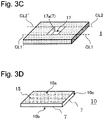
- a first opening 17 is formed in the plate-like base material 1 on which the heat generating resistor layer 15 is formed as shown in Fig. 3C .
- the first opening 17 may be formed, for example, by cutting the plate-like base material 1.
- the unplated regions 7 are accordingly formed in an opening side surface 17a that defines the first opening 17.
- the plate-like base material 1 is cut along a first cut line CL1 and a second cut line CL2 which extend from the first opening 17 to the side surface 1c.
- the second cut line CL2 preferably does not intersect with the first cut line CL1.
- the cutting of the plate-like base material 1 along the first cut line CL1 and the second cut line CL2 forms the unplated regions 7 in the plate-like base material 1. Consequently, as shown in Fig.
- the heat generating resistor layer 15 is formed, which extends from the main surface 10a through the side surface 10c (left-side surface on Fig. 3D ) to the rear surface 10b.
- the heater 10 is then obtained in which the three side surfaces 10c are the unplated regions 7.
- the plate-like base material 1 may be cut along a first cut line CL1' and a second cut line CL2' which extend from the first opening 17 to another side surface 1c.
- the second cut line CL2' preferably does not intersect with the first cut line CL1'.
- Another heater 10 is then obtained from the plate-like base material 1.
- the first cut line CL1 and the first cut line CL1' preferably extend in the same straight line. This makes it possible to cut the plate-like base material 1 along the first cut line CL1 and the first cut line CL1' without difficulty in a single cutting process. If the plate-like base material 1 is cut along two other cut lines extending from the first opening 17 to another side surface, another heater 10 is obtained.
- Figs. 4A to 4D are schematic views that explain a third example of the method of manufacturing the heater 10 shown in Fig. 1A .
- a plate-like base material 1 is prepared, which is material for the heater 10.
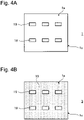
- the plate-like base material 1 is a rectangular plate as a whole and includes at least one second opening 19.
- the plate-like base material 1 includes six second openings 19. Two of the second openings 19 are arranged in a vertical direction in the figure, and three of the second openings 19 are arranged in a horizontal direction in the figure.
- the plate-like base material 1 includes a main surface 1a, a rear surface, not shown, and a side surface 1c connecting the main surface 1a and the rear surface 1b.
- the plate-like base material 1 may be prepared by any method.
- a plate-like member may be subjected to publicly-known processing, such as cutting machining to form second openings 19, to thereby fabricate the plate-like base material 1.
- the plate-like base material 1 also may be fabricated by filling a mold for molding a plate-like member having an opening portion with material such as thermosetting resin and hardening the material. A base material portion and the second openings 19 are thus formed at one time.
- a heat generating resistor layer 15 is formed on a surface of the plate-like base material 1 by plating.
- the heat generating resistor layer 15 may be formed by a publicly-known plating method, such as an electrolytic plating method and an electroless plating method. It is preferable, however, that the heat generating resistor layer 15 be formed by the electroless plating method.
- the heat generating resistor layer 15 is formed at least on a main surface 1a, a rear surface 1b, and opening side surfaces of the second openings 19.
- the heat generating resistor layer 15 does not have to be formed in a side surface 1c.
- the heat generating resistor layer 15 is formed by plating on the main surface 1a, the rear surface 1b, the side surface 1c, and the opening side surfaces of the second openings 19.
- the entire surface (namely the main surface 1a, the rear surface 1b, the side surface 1c, and the opening side surfaces of the second openings 19) of the plate-like base material 1 can be plated with the heat generating resistor layer 15 by immersing the entire plate-like base material 1 in plating solution containing metal, with which the heat generating resistor layer 15 is made.
- An unplated region 7 of the heater 10 is formed by extracting portions of the plate-like base material 1 which are located between the respective second openings 19 on one hand and the side surface 1c on the other from the plate-like base material 1 on which the heat generating resistor layer 15 is formed.
- the plate-like base material 1 is cut along third cut lines CL3 extending from the respective second openings 19 toward the side surface 1c and fourth cut lines CL4 extending from the respective second openings 19 toward the side surface 1c.
- the portions between the respective second openings 19 on one hand and the side surface 1c on the other can be thus extracted from the plate-like base material 1.
- the third cut lines CL3 or the fourth cut lines CL4 preferably extend in a linear manner toward the side surface 1c opposite to the opening side surfaces of the second openings 19 which corresponds to the side surface 10c of the heater 10 which includes the heat generating resistor layer 15.
- the fourth cut lines CL4 preferably do not intersect with the third cut lines CL3.
- the third cut lines CL3 and the fourth cut lines CL4 are preferably straight lines and parallel with each other. Instead of being straight lines, the third cut lines CL3 and the fourth cut lines CL4 may be curved lines, zigzag lines or other lines in freely selected shapes. In the example shown in Fig.
- the third cut lines CL3 and the fourth cut lines CL4 reach the side surface 1c of the plate-like base material 1.
- the third cut lines CL3 and the fourth cut lines CL4 may reach the cut lines CL.
- cutting directions along the cut lines may be freely decided.
- the portion between the second opening 19 and the side surface 1c which is extracted from the plate-like base material 1 includes unplated regions 7 in the side surface 1c and a cutting area along the third cut line CL3 and the fourth cut line CL4 and further includes the heat generating resistor layer 15 in a surface corresponding to the opening side surface of the second opening 19. In this case, therefore, the portion between the second opening 19 and the side surface 1c which is extracted from the plate-like base material 1 may be used as the heater 10.
- the heat generating resistor layer 15 is not formed on the side surface 1c of the plate-like base material 1, and the unplated region 7 is provided only to the side surface 1c.
- the heat generating resistor layer 15 is formed on the side surface 1c of the plate-like base material 1 as in the present embodiment, the heat generating resistor layer 15 formed on the side surface 1c of the plate-like base material 1 or the heat generating resistor layer 15 formed on the opening side surface of the second opening 19 is removed.
- the plate-like base material 1 is cut along the cut line CL that is orthogonal to the third cut line CL3 and the fourth cut line CL4 and removed including the side surface 1c.
- the unplated regions 7 are thus formed in the plate-like base material 1.
- the portion between the second opening 19 and the side surface 1c of the plate-like base material 1 which is extracted from the plate-like base material 1 includes a surface corresponding to the side surface 1c or the opening side surface of the second opening 19 and further includes unplated regions 7 in surfaces cut along the third cut line CL3 and the fourth cut line CL4.
- the heat generating resistor layer 15 on the side surface 1c may be removed by etching the heat generating resistor layer 15 on the side surface 1c of the plate-like base material 1 or cutting the heat generating resistor layer 15 on the side surface 1c of the plate-like base material 1.
- the heater 10 can be extracted.
- the plate-like base material 1 is cut along fifth cut lines CL5, sixth cut lines CL6, and seventh cut lines CL7 shown in Fig. 4C .
- Each of the fifth cut lines CL5 extends between a corresponding one of the second openings 19 and a corresponding other one of the second openings 19.
- Each of the sixth cut lines CL6 extends between a corresponding one of the second openings 19 and a corresponding other one of the second openings 19 so as not to intersect with the fifth cut lines CL5.
- Each of the seventh cut lines CL7 extends between a corresponding one of the fifth cut lines CL5 and a corresponding one of the sixth cut lines CL6. This makes it possible to extract two heaters 10 and form unplated regions 7 at the same time.
- the above-explained process manufactures twelve heaters 10 shown in Fig. 4D from portions between the respective second openings 19 and the side surface 1c and portions between the pair of second openings 19 and forms unplated regions 7 at the same time.
- the third cut lines CL3 and the fourth cut lines CL4 are preferably straight lines.
- the fifth cut lines CL5 and the sixth cut lines CL6 are preferably straight lines.
- the third cut lines CL3 and the fifth cut lines CL5 preferably extend in the same straight line. This makes it possible to cut the plate-like base material 1 from the third cut lines CL3 through to the fifth cut lines CL5 without difficulty in a single cutting process.
- the third cut lines CL3 and the fifth cut lines CL5 extend in the same straight line
- the fourth cut lines CL4 and the sixth cut lines CL6 extend in the same straight line
- the third cut lines CL3 and the fifth cut lines CL5 extend substantially parallel with the fourth cut lines CL4 and the sixth cut lines as shown in Fig. 4C . This makes it possible to uniform width of the heater 10 manufactured from the portion between the second opening 19 and the side surface 1c and width of the heater 10 manufactured from the portion between the second openings 19.
- a plurality of pairs of second openings 19 vertically arranged in the figure are adjacently located in the horizontal direction in the figure.
- the seventh cut line CL7 dividing the portion between one of the pairs of second openings 19 and the seventh cut line CL7 dividing the portion of the plate-like base material 1 which is located between the pair of second openings 19 and another pair of second openings 19 arranged in the horizontal direction in the figure preferably extend in the same straight line. This makes it possible to divide the portion between two adjacent pairs of second openings 19 in a single cutting process when the plurality of pairs of second openings 19 are adjacently located as shown in Fig. 4C .
- the seventh cut line CL7 preferably extends between a center of the fifth cut line CL5 and a center of the sixth cut line CL6. This makes it possible to uniform lengths of two heaters 10 extracted from the respective portions between the pairs of second openings 19 when the fifth cut line CL5 and the sixth cut line CL6 are straight lines.
- the heater 10 is manufactured from the portion of the plate-like base material 1 which is located between the pair of second openings 19 along the fifth cut line CL5, the sixth cut line CL6, and the seventh cut line CL7.
- the heater 10 may be manufactured by cutting the portion of the plate-like base material 1 which is located between the pair of second openings 19 along freely selected cut lines.
- the fifth cut line CL5 and the sixth cut line CL6 may intersect with each other to extend between one of the second openings 19 and another one of the second openings 19. In such a case, a portion of the plate-like base material 1 which is zoned by the fifth cut line CL5, the sixth cut line CL6, and the second opening 19 is extracted as the heater 10 without providing the seventh cut line CL7.
- the second openings 19 each have a rectangular shape.
- the shape of the second opening 19 is not limited.
- the second opening 19 may be of any shape, such as a rounded rectangle, a circle, and an ellipse.
- Fig. 5 is a schematic view that explains an example of the method for manufacturing the heater 10 shown in Fig. 1B .
- the second opening 19 has a shape of a hexagon that is obtained by connecting short sides of two trapezoids.
- the second opening 19 may have a shape obtained by rounding two obtuse angles of a shape of the second opening 19 in Fig. 5 .
- Fig. 7 is a schematic view that explains a fourth example of the method of manufacturing the heater 10.
- the plate-like base material 1 includes a plurality of second openings 19.
- the second openings 19 have shapes including a rectangle, an ellipse, and a hexagon obtained by connecting short sides of two trapezoids.
- the plate-like base material 1 shown in Fig. 7 may have the same structure except for the number and shape of the second openings 19 and size of the plate-like base material 1.
- the plate-like base material 1 may be cut along eighth cut lines CL8 and ninth cut lines CL9 as well as the third cut lines CL3, the fourth cut lines CL4, the fifth cut lines CL5, the sixth cut lines CL6, and the seventh cut lines C7.
- Each of the eighth cut line CL8 extends between a corresponding one of the second openings 19 and a corresponding other one of the second openings 19 so as not to intersect with the fifth cut lines CL5 and the sixth cut lines CL6.
- a portion between a pair of second openings 19 can be divided by cutting the plate-like base material 1 along the eighth cut line CL8. Any cut line extending between one of the second openings 19 and the other of the second openings 19 may be added.
- the ninth cut lines CL9 are different cut lines from the third cut lines CL3 and the fourth cut lines CL4.
- the ninth cut lines CL9 extend from the second openings 19 toward the side surface 1c.
- the ninth cut lines CL9 preferably do not intersect with the third cut lines CL3 and the fourth cut lines CL4.
- the heater 10 obtained from a portion between the second opening 19 and the side surface 1c can be divided by cutting the plate-like base material 1 along the ninth cut lines CL9. Any cut line extending from the second opening 19 toward the side surface 1c may be added.
- the heater 10 can be obtained, in which the heat generating resistor layer 15 is provided in part of the main surface 10a, the rear surface 10b, and the side surface 10c.
- An electrode 21 may be formed on each of the main surface 10a and the rear surface 10b of the heater 10. Specifically, it is preferable that the electrodes 21 be formed at a farthest possible position in the main surface 10a and the rear surface 10b from the side surface 10c on which the heat generating resistor layer 15 is formed.
- the electrodes 21 may be made with a publicly-known material, such as a metal sheet.
- the heat generating resistor layer 15 does not have to be provided to the entire of the main surface 10a or the rear surface 10b.
- the heat generating resistor layer 15 therefore may be partially removed from the main surface 10a or the rear surface 10b.
- a resistance value may be increased by elongating a cable run distance by applying the patterning to the heat generating resistor layer 15 in such a manner that a cable run of the main surface 10a or the rear surface 10b which extends between the side surface 10c on which the heat generating resistor layer 15 is formed and the opposite side surface 10c is curved.
- a first mode provides a method for manufacturing a heater for heating a flavor source in which a heat generating resistor layer is formed on a main surface, a rear surface, and one side surface.
- the method includes the steps of forming the heat generating resistor layer on a surface of a plate-like base material by plating, and forming an unplated region on the plate-like base material on which the heat generating resistor layer is formed.
- the step of forming the heat generating resistor layer includes forming the heat generating resistor layer on a main surface, a rear surface, and a side surface of the plate-like base material.
- the step of forming the unplated region includes removing the heat generating resistor layer formed on the side surface from the plate-like base material with part left on the side surface.
- the step of forming the unplated region includes forming a first opening in the plate-like base material on which the heat generating resistor layer is formed, and cutting the plate-like base material along a first cut line extending between the first opening and the side surface and a second cut line that extends between the first opening and the side surface and does not intersect with the first cut line.
- the plate-like base material includes a second opening
- the step of forming the heat generating resistor layer includes forming the heat generating resistor layer at least on the main surface, the rear surface, and an opening side surface of the plate-like base material which defines the second opening.
- the step of forming the unplated region includes extracting from the plate-like base material a portion between the second opening and a side surface of the plate-like base material.
- the step of forming the unplated region includes cutting the plate-like base material along a third cut line extending from the second opening toward the side surface of the plate-like base material and a fourth cut line extending from the second opening toward the side surface.
- the step of forming the unplated region includes removing the heat generating resistor layer formed on the side surface of the plate-like base material or the heat generating resistor layer formed on the opening side surface.
- the plate-like base material includes the second opening comprising a pair of second openings
- the step of forming the unplated region includes dividing a portion of the plate-like base material which is located between the pair of second openings in a direction where the pair of second openings are arranged.
- the step of forming the unplated region includes cutting the plate-like base material along a fifth cut line extending between one of the second openings and the other of the second openings, a sixth cut line that extends between one of the second openings and the other of the second openings and does not intersect with the fifth cut line, and a seventh cut line that extends between the fifth cut line and the sixth cut line and divides a portion of the plate-like base material which is located between the pair of second openings.
- the fifth cut line and the sixth cut line are straight lines extending between one of the second openings and the other of the second openings.
- the seventh cut line is a straight line extending between a center of the fifth cut line and a center of the sixth cut line.
- the third cut line and the fifth cut line extend in the same straight line
- the fourth cut line and the sixth cut line extend in the same straight line.
- the third cut line and the fifth cut line are substantially parallel to the fourth cut line and the sixth cut line.
- the step of forming the unplated region includes cutting the plate-like base material along an eighth cut line extending between one of the second openings and the other of the second openings, and the eighth cut line does not intersect with the fifth cut line and the sixth cut line.
- the plate-like base material includes another pair of second openings adjacent to the pair of second openings, and the seventh cut line dividing the portion of the plate-like base material which is located between the pair of second openings and the seventh cut line dividing a portion of the plate-like base material which is located between the another pair of second openings extend in the same straight line.
- the method for manufacturing a heater for heating a flavor source includes the step of forming an electrode on each of the main surface and the rear surface of the heater for heating the flavor source.
Landscapes
- Chemical & Material Sciences (AREA)
- Engineering & Computer Science (AREA)
- Ceramic Engineering (AREA)
- Resistance Heating (AREA)
- Surface Heating Bodies (AREA)
Abstract
Description
- The invention relates to a method for manufacturing a heater for heating a flavor source.
- A heater that has been known as a heater for heating a flavor source is made by arranging specific metal, such as molybdenum and tungsten, on pre-sintered ceramic as a heat generating resistor layer precursor and then forming a heat generating resistor on a ceramic base material during sintering. A heater which is provided with a heat generating resistor layer by direct lithography on a base material using plating technology has also been known (
Patent Literatures 1 and 2, for example). -
- A method for providing a heat generating resistor layer precursor on pre-sintered ceramic is limited in kinds of metal materials that can be used and is limited in freedom of heater designing. Using the methods disclosed in
Patent Literatures 1 and 2 increases the freedom of heater designing, but the methods are complicated. In this light, an issue of the invention is to provide a method for manufacturing a heater for heating a flavor source by a simpler method. - According to one mode, there is provided a method for manufacturing a heater for heating a flavor source in which a heat generating resistor layer is formed on a main surface, a rear surface, and one side surface. The method includes the steps of forming the heat generating resistor layer on a surface of a plate-like base material by plating, and forming an unplated region on the plate-like base material on which the heat generating resistor layer is formed.
- The invention makes it possible to manufacture a heater for heating a flavor source by a simpler method.
-
-
Fig. 1A is a perspective view showing one example of a heater for heating a flavor source which is manufactured by a manufacturing method according to an embodiment of the invention. -
Fig. 1B is a perspective view showing another example of the heater for heating a flavor source which is manufactured by the manufacturing method according to the embodiment of the invention. -
Fig. 2A is a schematic perspective view that explains a first example of a method for manufacturing the heater shown inFig. 1A . -
Fig. 2B is a schematic perspective view that explains the first example of the method for manufacturing the heater shown inFig. 1A . -
Fig. 2C is a schematic perspective view that explains the first example of the method for manufacturing the heater shown inFig. 1A . -
Fig. 2D is a schematic perspective view that explains the first example of the method for manufacturing the heater shown inFig. 1A . -
Fig. 3A is a schematic perspective view that explains a second example of the method for manufacturing the heater shown inFig. 1A . -
Fig. 3B is a schematic perspective view that explains the second example of the method for manufacturing the heater shown inFig. 1A . -
Fig. 3C is a schematic perspective view that explains the second example of the method for manufacturing the heater shown inFig. 1A . -
Fig. 3D is a schematic perspective view that explains the second example of the method for manufacturing the heater shown inFig. 1A . -
Fig. 4A is a perspective view that explains a third example of the method for manufacturing the heater shown inFig. 1A . -
Fig. 4B is a perspective view that explains the third example of the method for manufacturing the heater shown inFig. 1A . -
Fig. 4C is a perspective view that explains the third example of the method for manufacturing the heater shown inFig. 1A . -
Fig. 4D is a perspective view that explains the third example of the method for manufacturing the heater shown inFig. 1A . -
Fig. 5 is a schematic view that explains an example of the method for manufacturing the heater shown inFig. 1B . -
Fig. 6 is a schematic view showing a shape of a second opening. -
Fig. 7 is a schematic view that explains a fourth example of the heater manufacturing method. - Embodiments of the invention will be explained with reference to the attached drawings. Similar or corresponding constituent elements in the figures explained below are provided with similar reference signs, and overlapping explanation will be omitted.
Fig. 1A is a perspective view showing one example of a heater for heating a flavor source which is manufactured by a manufacturing method according to an embodiment of the invention.Fig. 1B is a perspective view showing another example of the heater for heating a flavor source which is manufactured by the manufacturing method according to the embodiment of the invention. Aheater 10 for heating a flavor source (hereinafter, referred to simply as "heater") is a heater for heating a flavor source without burning. The flavor source is material of tobacco or the like which can generate a flavor. Theheater 10 is inserted in the flavor source and therefore preferably has a substantially plate-like shape as a whole as shown inFigs. 1A and 1B . Theheater 10 may have a bar-like or columnar shape. - The
heater 10 includes amain surface 10a, arear surface 10b that is an opposite surface from themain surface 10a, and aside surface 10c connecting themain surface 10a and therear surface 10b. In the present specification, themain surface 10a and therear surface 10b are surfaces having largest area of theheater 10. According to an example shown inFigs. 1A and 1B , theheater 10 includes a heat generatingresistor layer 15 formed on themain surface 10a and therear surface 10b. The heat generating resistor is material, such as metal, which generates heat when energized. The heat generating resistor may be made, for example, of tungsten, copper or the like. The heatgenerating resistor layer 15 preferably has a thickness ranging from 10 µm to 30 µm, both inclusive. - The heat
generating resistor layer 15 is formed on part of theside surface 10c. In other words, theside surface 10c includes anunplated region 7 where the heat generatingresistor layer 15 is not formed. Theheater 10 may include a pair ofelectrodes 21, one of which is connected to themain surface 10a and the other to therear surface 10b. The pair ofelectrodes 21, themain surface 10a, theside surface 10c including the heat generatingresistor layer 15, and therear surface 10b thus form a pathway, through which electric current flows. In order to elongate a pathway for electric current that flows in the heat generatingresistor layer 15, theelectrodes 21 are preferably formed at a farthest possible position in themain surface 10 a and therear surface 10b from theside surface 10c on which the heat generatingresistor layer 15 is formed. - The
heater 10, for example, may be inserted in the flavor source in such a manner that theside surface 10c on which the heat generatingresistor layer 15 is formed is located at a distal end. As shown inFig. 1A , the distal end viewed from themain surface 10a of theheater 10 has a linear shape. InFig. 1B , the distal end viewed from themain surface 10a of theheater 10 has a convex shape with an acute angle. The distal end viewed from themain surface 10a of theheater 10 is not limited to the foregoing shapes and may have a curved convex shape. - According to one mode, the
heater 10 preferably has a thickness ranging from 0.1 mm to 5.0 mm, both inclusive, and more preferably from 0.3 mm to 1.0 mm, both inclusive. According to one mode, theheater 10 preferably has a width ranging from 1 mm to 50 mm, both inclusive, and more preferably from 3.0 mm to 7.0 mm, both inclusive. According to one mode, theheater 10 preferably has a length ranging from 3 mm to 100 mm, both inclusive, and more preferably from 10 mm to 30 mm, both inclusive. In the present specification, the thickness of theheater 10 refers to length between themain surface 10a and therear surface 10b. The length of theheater 10 refers to length in a direction where theheater 10 is inserted into the flavor source, and the width of theheater 10 refers to a direction orthogonal to the direction where theheater 10 is inserted into the flavor source. - In another mode, the
heater 10 may be a rod-like (bar-like) heater having a round cross-section which is formed by chamfering a tangent line between themain surface 10a of theheater 10 and theside surface 10c in which theunplated region 7 is formed. - A method for manufacturing the
heater 10 shown inFigs. 1A and 1B will be now explained.Figs. 2A to 2D are schematic perspective views that explain a first example of the method for manufacturing theheater 10 shown inFig. 1A . First, as shownFig. 2A , a plate-like base material 1 is prepared, which is material for theheater 10. According to the example shown in the figures, the plate-like base material 1 is a rectangular plate. The plate-like base material 1 includes amain surface 1a, arear surface 1b, and aside surface 1c connecting themain surface 1a and therear surface 1b. The plate-like base material 1 can be made of a publicly-known insulating material. Such materials include, for example, heat resistant polymer, such as engineering plastic and heat-curable resin, and ceramic. Size of the plate-like base material 1 is determined by the shape of theheater 10 that is obtained at the end. - As shown in
Fig. 2B , the heat generatingresistor layer 15 is formed on a surface of the plate-like base material 1 by plating. The heatgenerating resistor layer 15 may be formed, for example, by a publicly-known plating method, such as an electrolytic plating method and an electroless plating method. However, it is preferable that the heat generatingresistor layer 15 be formed by the electroless plating method. According to the present embodiment, plating is applied to the surface of the plate-like base material 1. From a perspective of workability, it is preferable to apply plating to themain surface 1a, therear surface 1b, and at least part of theside surface 1c. It is more preferable to apply plating to the entire of the main, rear, andside surfaces Fig. 2B shows the plate-like base material 1 in which plating is applied to the entire of the main, rear, andside surfaces resistor layer 15 is formed by the electroless plating method, the entire surface (namely themain surface 1a, therear surface 1b, and theside surface 1c) of the plate-like base material 1 can be plated with the heat generatingresistor layer 15 by immersing the entire plate-like base material 1 in plating solution containing metal, with which the heat generatingresistor layer 15 is made. - The
unplated region 7 is then formed in the plate-like base material 1 on which the heat generatingresistor layer 15 is formed. Specifically, the heat generatingresistor layer 15 formed on theside surface 1c is removed from the plate-like base material 1 with part left on theside surface 1c. For example, as shown inFig. 2C , theside surface 1c at three sides of the plate-like base material 1 is removed by cutting along cut lines CL while maintaining part of theside surface 1c. Theunplated region 7 is thus formed on the plate-like base material 1. A publicly-known cutting machine may be used to cut the plate-like base material 1. The publicly-known cutting machine may be a cutter, such as a diamond cutter, a press-cutting machine or the like. Instead of removing the heat generatingresistor layer 15 in the above-described manner, the heat generatingresistor layer 15 on theside surface 1c may be removed with part left on theside surface 1c by masking a region of the plate-like base material 1 on which the heat generatingresistor layer 15 is to be maintained, and etching the heat generatingresistor layer 15 on the other region of theside surface 1c of the plate-like base material 1. The heatgenerating resistor layer 15 on theside surface 1c may also be removed with part left on theside surface 1c by cutting the heat generatingresistor layer 15 on theside surface 1c of the plate-like base material 1. It is preferable from a standpoint of simplification of the manufacturing process to cut the plate-like base material 1 along the cut lines CL as shown inFig. 2C and remove the plate-like base material 1 including theside surface 1c. - If the process explained above with reference to
Figs. 2A to 2C is carried out, theheater 10 is obtained, which includes the heat generatingresistor layer 15 extending from themain surface 10a through theside surface 10c (left-side surface onFig. 2D ) to therear surface 10b as shown inFig. 2D . Theheater 10 includes theside surface 10c comprising threeside surfaces 10c which areunplated regions 7, so that a short circuit is prevented from occurring at energization of themain surface 10a and therear surface 10b. The heatgenerating resistor layer 15 may be provided on the entire or part of the main, rear, andside surfaces like base material 1. -
Figs. 3A to 3D are schematic perspective views that explain a second example of the method for manufacturing theheater 10 shown inFig. 1A . First, as shown inFig. 3A , a plate-like base material 1 similar to the plate-like base material 1 inFig. 2A is prepared. As shown inFig. 3B , similarly toFig. 2B , plating is applied to the entire of the main, rear, andside surfaces like base material 1. As explained above with reference toFig. 2B , plating is applied to themain surface 1a, therear surface 1b, and at least part of theside surface 1c. - A
first opening 17 is formed in the plate-like base material 1 on which the heat generatingresistor layer 15 is formed as shown inFig. 3C . Thefirst opening 17 may be formed, for example, by cutting the plate-like base material 1. Theunplated regions 7 are accordingly formed in anopening side surface 17a that defines thefirst opening 17. Subsequently, the plate-like base material 1 is cut along a first cut line CL1 and a second cut line CL2 which extend from thefirst opening 17 to theside surface 1c. The second cut line CL2 preferably does not intersect with the first cut line CL1. The cutting of the plate-like base material 1 along the first cut line CL1 and the second cut line CL2 forms theunplated regions 7 in the plate-like base material 1. Consequently, as shown inFig. 3D , the heat generatingresistor layer 15 is formed, which extends from themain surface 10a through theside surface 10c (left-side surface onFig. 3D ) to therear surface 10b. Theheater 10 is then obtained in which the threeside surfaces 10c are theunplated regions 7. - The plate-
like base material 1 may be cut along a first cut line CL1' and a second cut line CL2' which extend from thefirst opening 17 to anotherside surface 1c. The second cut line CL2' preferably does not intersect with the first cut line CL1'. Anotherheater 10 is then obtained from the plate-like base material 1. - The first cut line CL1 and the first cut line CL1' preferably extend in the same straight line. This makes it possible to cut the plate-
like base material 1 along the first cut line CL1 and the first cut line CL1' without difficulty in a single cutting process. If the plate-like base material 1 is cut along two other cut lines extending from thefirst opening 17 to another side surface, anotherheater 10 is obtained. -
Figs. 4A to 4D are schematic views that explain a third example of the method of manufacturing theheater 10 shown inFig. 1A . First, as shown inFig. 4A , a plate-like base material 1 is prepared, which is material for theheater 10. The plate-like base material 1 is a rectangular plate as a whole and includes at least onesecond opening 19. In the example shown in the figure, the plate-like base material 1 includes sixsecond openings 19. Two of thesecond openings 19 are arranged in a vertical direction in the figure, and three of thesecond openings 19 are arranged in a horizontal direction in the figure. The plate-like base material 1 includes amain surface 1a, a rear surface, not shown, and aside surface 1c connecting themain surface 1a and therear surface 1b. - The plate-
like base material 1 may be prepared by any method. For example, a plate-like member may be subjected to publicly-known processing, such as cutting machining to formsecond openings 19, to thereby fabricate the plate-like base material 1. The plate-like base material 1 also may be fabricated by filling a mold for molding a plate-like member having an opening portion with material such as thermosetting resin and hardening the material. A base material portion and thesecond openings 19 are thus formed at one time. - Next, as shown in
Fig. 4B , a heat generatingresistor layer 15 is formed on a surface of the plate-like base material 1 by plating. The heatgenerating resistor layer 15 may be formed by a publicly-known plating method, such as an electrolytic plating method and an electroless plating method. It is preferable, however, that the heat generatingresistor layer 15 be formed by the electroless plating method. - The heat
generating resistor layer 15 is formed at least on amain surface 1a, arear surface 1b, and opening side surfaces of thesecond openings 19. The heatgenerating resistor layer 15 does not have to be formed in aside surface 1c. According to the present embodiment, the heat generatingresistor layer 15 is formed by plating on themain surface 1a, therear surface 1b, theside surface 1c, and the opening side surfaces of thesecond openings 19. If the heat generatingresistor layer 15 is formed by the electroless plating method, the entire surface (namely themain surface 1a, therear surface 1b, theside surface 1c, and the opening side surfaces of the second openings 19) of the plate-like base material 1 can be plated with the heat generatingresistor layer 15 by immersing the entire plate-like base material 1 in plating solution containing metal, with which the heat generatingresistor layer 15 is made. - An
unplated region 7 of theheater 10 is formed by extracting portions of the plate-like base material 1 which are located between the respectivesecond openings 19 on one hand and theside surface 1c on the other from the plate-like base material 1 on which the heat generatingresistor layer 15 is formed. To be specific, as shown inFig. 4C , the plate-like base material 1 is cut along third cut lines CL3 extending from the respectivesecond openings 19 toward theside surface 1c and fourth cut lines CL4 extending from the respectivesecond openings 19 toward theside surface 1c. The portions between the respectivesecond openings 19 on one hand and theside surface 1c on the other can be thus extracted from the plate-like base material 1. Specifically, as shown inFig. 4C , the third cut lines CL3 or the fourth cut lines CL4 preferably extend in a linear manner toward theside surface 1c opposite to the opening side surfaces of thesecond openings 19 which corresponds to theside surface 10c of theheater 10 which includes the heat generatingresistor layer 15. The fourth cut lines CL4 preferably do not intersect with the third cut lines CL3. As shown inFig. 4C , the third cut lines CL3 and the fourth cut lines CL4 are preferably straight lines and parallel with each other. Instead of being straight lines, the third cut lines CL3 and the fourth cut lines CL4 may be curved lines, zigzag lines or other lines in freely selected shapes. In the example shown inFig. 4C , the third cut lines CL3 and the fourth cut lines CL4 reach theside surface 1c of the plate-like base material 1. However, the third cut lines CL3 and the fourth cut lines CL4 may reach the cut lines CL. In the present specification, cutting directions along the cut lines may be freely decided. - If the heat generating
resistor layer 15 is not formed on theside surface 1c of the plate-like base material 1, the portion between thesecond opening 19 and theside surface 1c which is extracted from the plate-like base material 1 includesunplated regions 7 in theside surface 1c and a cutting area along the third cut line CL3 and the fourth cut line CL4 and further includes the heat generatingresistor layer 15 in a surface corresponding to the opening side surface of thesecond opening 19. In this case, therefore, the portion between thesecond opening 19 and theside surface 1c which is extracted from the plate-like base material 1 may be used as theheater 10. For example, if theside surface 1c is masked before the plate-like base material 1 is subjected to electroless plating, the heat generatingresistor layer 15 is not formed on theside surface 1c of the plate-like base material 1, and theunplated region 7 is provided only to theside surface 1c. - If the heat generating
resistor layer 15 is formed on theside surface 1c of the plate-like base material 1 as in the present embodiment, the heat generatingresistor layer 15 formed on theside surface 1c of the plate-like base material 1 or the heat generatingresistor layer 15 formed on the opening side surface of thesecond opening 19 is removed. In the example shown inFig. 4C , the plate-like base material 1 is cut along the cut line CL that is orthogonal to the third cut line CL3 and the fourth cut line CL4 and removed including theside surface 1c. Theunplated regions 7 are thus formed in the plate-like base material 1. Accordingly, the portion between thesecond opening 19 and theside surface 1c of the plate-like base material 1 which is extracted from the plate-like base material 1 includes a surface corresponding to theside surface 1c or the opening side surface of thesecond opening 19 and further includesunplated regions 7 in surfaces cut along the third cut line CL3 and the fourth cut line CL4. The heatgenerating resistor layer 15 on theside surface 1c may be removed by etching the heat generatingresistor layer 15 on theside surface 1c of the plate-like base material 1 or cutting the heat generatingresistor layer 15 on theside surface 1c of the plate-like base material 1. - With regard to the plate-
like base material 1 shown inFig. 4C , if a portion between a pair ofsecond openings 19 of the plate-like base material 1 is divided in a direction where the pair ofsecond openings 19 are arranged, theheater 10 can be extracted. Specifically, the plate-like base material 1 is cut along fifth cut lines CL5, sixth cut lines CL6, and seventh cut lines CL7 shown inFig. 4C . Each of the fifth cut lines CL5 extends between a corresponding one of thesecond openings 19 and a corresponding other one of thesecond openings 19. Each of the sixth cut lines CL6 extends between a corresponding one of thesecond openings 19 and a corresponding other one of thesecond openings 19 so as not to intersect with the fifth cut lines CL5. Each of the seventh cut lines CL7 extends between a corresponding one of the fifth cut lines CL5 and a corresponding one of the sixth cut lines CL6. This makes it possible to extract twoheaters 10 and formunplated regions 7 at the same time. - The above-explained process manufactures twelve
heaters 10 shown inFig. 4D from portions between the respectivesecond openings 19 and theside surface 1c and portions between the pair ofsecond openings 19 and formsunplated regions 7 at the same time. - In the example shown in
Fig. 4C , the third cut lines CL3 and the fourth cut lines CL4 are preferably straight lines. The fifth cut lines CL5 and the sixth cut lines CL6 are preferably straight lines. The third cut lines CL3 and the fifth cut lines CL5 preferably extend in the same straight line. This makes it possible to cut the plate-like base material 1 from the third cut lines CL3 through to the fifth cut lines CL5 without difficulty in a single cutting process. As shown inFig. 4C , it is preferable that the fourth cut lines CL4 and the sixth cut lines CL6 extend in a straight line. This makes it possible to cut the plate-like base material 1 from the fourth cut lines CL4 through to the sixth cut lines CL6 without difficulty in a single cutting process. - When the third cut lines CL3 and the fifth cut lines CL5 extend in the same straight line, and the fourth cut lines CL4 and the sixth cut lines CL6 extend in the same straight line, it is preferable that the third cut lines CL3 and the fifth cut lines CL5 extend substantially parallel with the fourth cut lines CL4 and the sixth cut lines as shown in
Fig. 4C . This makes it possible to uniform width of theheater 10 manufactured from the portion between thesecond opening 19 and theside surface 1c and width of theheater 10 manufactured from the portion between thesecond openings 19. - In the example shown in
Fig. 4C , a plurality of pairs ofsecond openings 19 vertically arranged in the figure are adjacently located in the horizontal direction in the figure. As shown inFig. 4C , the seventh cut line CL7 dividing the portion between one of the pairs ofsecond openings 19 and the seventh cut line CL7 dividing the portion of the plate-like base material 1 which is located between the pair ofsecond openings 19 and another pair ofsecond openings 19 arranged in the horizontal direction in the figure preferably extend in the same straight line. This makes it possible to divide the portion between two adjacent pairs ofsecond openings 19 in a single cutting process when the plurality of pairs ofsecond openings 19 are adjacently located as shown inFig. 4C . - The seventh cut line CL7 preferably extends between a center of the fifth cut line CL5 and a center of the sixth cut line CL6. This makes it possible to uniform lengths of two
heaters 10 extracted from the respective portions between the pairs ofsecond openings 19 when the fifth cut line CL5 and the sixth cut line CL6 are straight lines. - In the example shown in
Fig. 4C , theheater 10 is manufactured from the portion of the plate-like base material 1 which is located between the pair ofsecond openings 19 along the fifth cut line CL5, the sixth cut line CL6, and the seventh cut line CL7. Instead of manufacturing theheater 10 in the above-described manner, theheater 10 may be manufactured by cutting the portion of the plate-like base material 1 which is located between the pair ofsecond openings 19 along freely selected cut lines. For example, the fifth cut line CL5 and the sixth cut line CL6 may intersect with each other to extend between one of thesecond openings 19 and another one of thesecond openings 19. In such a case, a portion of the plate-like base material 1 which is zoned by the fifth cut line CL5, the sixth cut line CL6, and thesecond opening 19 is extracted as theheater 10 without providing the seventh cut line CL7. - In the examples shown in
Figs. 4A to 4D , thesecond openings 19 each have a rectangular shape. However, the shape of thesecond opening 19 is not limited. Thesecond opening 19 may be of any shape, such as a rounded rectangle, a circle, and an ellipse.Fig. 5 is a schematic view that explains an example of the method for manufacturing theheater 10 shown inFig. 1B . As shown inFig. 5 , thesecond opening 19 has a shape of a hexagon that is obtained by connecting short sides of two trapezoids. The plate-like base material 1 shown inFig. 5 may be cut along the third cut lines CL3, the fourth cut lines CL4, the fifth cut lines CL5, the sixth cut lines CL6, and the seventh cut lines CL7 as explained above with reference toFig. 4C . This makes it possible to obtain twelveheaters 10 in a convex shape with an acute angle as shown inFig. 2 . As shown inFig. 6 , for example, thesecond opening 19 may have a shape obtained by rounding two obtuse angles of a shape of thesecond opening 19 inFig. 5 . -
Fig. 7 is a schematic view that explains a fourth example of the method of manufacturing theheater 10. In the example shown inFig. 7 , the plate-like base material 1 includes a plurality ofsecond openings 19. As shown in the figure, thesecond openings 19 have shapes including a rectangle, an ellipse, and a hexagon obtained by connecting short sides of two trapezoids. The plate-like base material 1 shown inFig. 7 may have the same structure except for the number and shape of thesecond openings 19 and size of the plate-like base material 1. In the example shown inFig. 7 , the plate-like base material 1 may be cut along eighth cut lines CL8 and ninth cut lines CL9 as well as the third cut lines CL3, the fourth cut lines CL4, the fifth cut lines CL5, the sixth cut lines CL6, and the seventh cut lines C7. - Each of the eighth cut line CL8 extends between a corresponding one of the
second openings 19 and a corresponding other one of thesecond openings 19 so as not to intersect with the fifth cut lines CL5 and the sixth cut lines CL6. A portion between a pair ofsecond openings 19 can be divided by cutting the plate-like base material 1 along the eighth cut line CL8. Any cut line extending between one of thesecond openings 19 and the other of thesecond openings 19 may be added. - The ninth cut lines CL9 are different cut lines from the third cut lines CL3 and the fourth cut lines CL4. The ninth cut lines CL9 extend from the
second openings 19 toward theside surface 1c. The ninth cut lines CL9 preferably do not intersect with the third cut lines CL3 and the fourth cut lines CL4. Theheater 10 obtained from a portion between thesecond opening 19 and theside surface 1c can be divided by cutting the plate-like base material 1 along the ninth cut lines CL9. Any cut line extending from thesecond opening 19 toward theside surface 1c may be added. - According to the manufacturing method explained above, the
heater 10 can be obtained, in which the heat generatingresistor layer 15 is provided in part of themain surface 10a, therear surface 10b, and theside surface 10c. Anelectrode 21 may be formed on each of themain surface 10a and therear surface 10b of theheater 10. Specifically, it is preferable that theelectrodes 21 be formed at a farthest possible position in themain surface 10a and therear surface 10b from theside surface 10c on which the heat generatingresistor layer 15 is formed. Theelectrodes 21 may be made with a publicly-known material, such as a metal sheet. - In the
heater 10 manufactured by the manufacturing method explained above, the heat generatingresistor layer 15 does not have to be provided to the entire of themain surface 10a or therear surface 10b. The heatgenerating resistor layer 15 therefore may be partially removed from themain surface 10a or therear surface 10b. In this case, a resistance value may be increased by elongating a cable run distance by applying the patterning to the heat generatingresistor layer 15 in such a manner that a cable run of themain surface 10a or therear surface 10b which extends between theside surface 10c on which the heat generatingresistor layer 15 is formed and theopposite side surface 10c is curved. - The embodiments of the invention have been explained. The invention is not limited to the embodiments and may be modified in various ways in the range of the technical ideas described in the claims, description, and drawing. Any shape and material that are not directly mentioned in the description and drawings are in the range of technical idea of the invention as long as they provide the operation and advantageous effects of the invention.
- Some modes disclosed in the present application will be discussed below.
- A first mode provides a method for manufacturing a heater for heating a flavor source in which a heat generating resistor layer is formed on a main surface, a rear surface, and one side surface. The method includes the steps of forming the heat generating resistor layer on a surface of a plate-like base material by plating, and forming an unplated region on the plate-like base material on which the heat generating resistor layer is formed.
- In a second mode according to the first mode, the step of forming the heat generating resistor layer includes forming the heat generating resistor layer on a main surface, a rear surface, and a side surface of the plate-like base material.
- In a third mode according to the second mode, the step of forming the unplated region includes removing the heat generating resistor layer formed on the side surface from the plate-like base material with part left on the side surface.
- In a fourth mode according to the second or third mode, the step of forming the unplated region includes forming a first opening in the plate-like base material on which the heat generating resistor layer is formed, and cutting the plate-like base material along a first cut line extending between the first opening and the side surface and a second cut line that extends between the first opening and the side surface and does not intersect with the first cut line.
- In a fifth mode according to the first or second mode, the plate-like base material includes a second opening, and the step of forming the heat generating resistor layer includes forming the heat generating resistor layer at least on the main surface, the rear surface, and an opening side surface of the plate-like base material which defines the second opening.
- In a sixth mode according to the fifth mode, the step of forming the unplated region includes extracting from the plate-like base material a portion between the second opening and a side surface of the plate-like base material.
- In a seventh mode according to the sixth mode, the step of forming the unplated region includes cutting the plate-like base material along a third cut line extending from the second opening toward the side surface of the plate-like base material and a fourth cut line extending from the second opening toward the side surface.
- In an eighth mode according to any one of the fifth to seventh modes referring to the second mode, the step of forming the unplated region includes removing the heat generating resistor layer formed on the side surface of the plate-like base material or the heat generating resistor layer formed on the opening side surface.
- In a ninth mode according to any one of the fifth to eighth modes, the plate-like base material includes the second opening comprising a pair of second openings, and the step of forming the unplated region includes dividing a portion of the plate-like base material which is located between the pair of second openings in a direction where the pair of second openings are arranged.
- In a 10th mode according to the ninth mode, the step of forming the unplated region includes cutting the plate-like base material along a fifth cut line extending between one of the second openings and the other of the second openings, a sixth cut line that extends between one of the second openings and the other of the second openings and does not intersect with the fifth cut line, and a seventh cut line that extends between the fifth cut line and the sixth cut line and divides a portion of the plate-like base material which is located between the pair of second openings.
- In an 11th mode according the tenth mode, the fifth cut line and the sixth cut line are straight lines extending between one of the second openings and the other of the second openings.
- In a 12th mode according to the 10th or 11th mode, the seventh cut line is a straight line extending between a center of the fifth cut line and a center of the sixth cut line.
- In a 13th mode according to any one of the 10th to 12th modes referring to the seventh mode, the third cut line and the fifth cut line extend in the same straight line, and the fourth cut line and the sixth cut line extend in the same straight line.
- In a 14th mode according to the 13th mode, the third cut line and the fifth cut line are substantially parallel to the fourth cut line and the sixth cut line.
- In a 15th mode according to any one of the 10th to 14th modes, the step of forming the unplated region includes cutting the plate-like base material along an eighth cut line extending between one of the second openings and the other of the second openings, and the eighth cut line does not intersect with the fifth cut line and the sixth cut line.
- In a 16th mode according to any one of the 10th to 15th modes, the plate-like base material includes another pair of second openings adjacent to the pair of second openings, and the seventh cut line dividing the portion of the plate-like base material which is located between the pair of second openings and the seventh cut line dividing a portion of the plate-like base material which is located between the another pair of second openings extend in the same straight line.
- In a 17th mode according to any one of the first to 16th modes, the method for manufacturing a heater for heating a flavor source includes the step of forming an electrode on each of the main surface and the rear surface of the heater for heating the flavor source.
-
- 1: Plate-like base material
- 7: Unplated region
- 10: Heater
- 10a: Main surface
- 10b: Rear surface
- 10c: Side surface
- 15: Heat generating resistor layer
- 17: First opening
- 17a: Opening side surface
- 19: Second opening
- 21: Electrode
- CL1: First cut line
- CL1': First cut line
- CL2: Second cut line
- CL2': Second cut line
- CL3: Third cut line
- CL4: Fourth cut line
- CL5: Fifth cut line
- CL6: Sixth cut line
- CL7: Seventh cut line
- CL8: Eighth cut line
Claims (17)
- A method for manufacturing a heater for heating a flavor source in which a heat generating resistor layer is formed on a main surface, a rear surface, and one side surface, comprising the steps of:forming the heat generating resistor layer on a surface of a plate-like base material by plating, andforming an unplated region on the plate-like base material on which the heat generating resistor layer is formed.
- The method for manufacturing a heater for heating a flavor source according to Claim 1,
wherein the step of forming the heat generating resistor layer includes forming the heat generating resistor layer on a main surface, a rear surface, and a side surface of the plate-like base material. - The method for manufacturing a heater for heating a flavor source according to Claim 2,
wherein the step of forming the unplated region includes removing the heat generating resistor layer formed on the side surface from the plate-like base material with part left on the side surface. - The method for manufacturing a heater for heating a flavor source according to Claim 2 or 3,
wherein the step of forming the unplated region includes:forming a first opening in the plate-like base material on which the heat generating resistor layer is formed, andcutting the plate-like base material along a first cut line extending between the first opening and the side surface and a second cut line that extends between the first opening and the side surface and does not intersect with the first cut line. - The method for manufacturing a heater for heating a flavor source according to Claim 1 or 2,wherein the plate-like base material includes a second opening, andwherein the step of forming the heat generating resistor layer includes forming the heat generating resistor layer at least on the main surface, the rear surface, and an opening side surface of the plate-like base material which defines the second opening.
- The method for manufacturing a heater for heating a flavor source according to Claim 5,
wherein the step of forming the unplated region includes extracting from the plate-like base material a portion between the second opening and a side surface of the plate-like base material. - The method for manufacturing a heater for heating a flavor source according to Claim 6,
wherein the step of forming the unplated region includes cutting the plate-like base material along a third cut line extending from the second opening toward the side surface of the plate-like base material and a fourth cut line extending from the second opening toward the side surface. - The method for manufacturing a heater for heating a flavor source according to any one of Claims 5 to 7 referring to Claim 2,
wherein the step of forming the unplated region includes removing the heat generating resistor layer formed on the side surface of the plate-like base material or the heat generating resistor layer formed on the opening side surface. - The method for manufacturing a heater for heating a flavor source according to any one of Claims 5 to 8,wherein the plate-like base material includes the second opening comprising a pair of second openings, andwherein the step of forming the unplated region includes dividing a portion of the plate-like base material which is located between the pair of second openings in a direction where the pair of second openings are arranged.
- The method for manufacturing a heater for heating a flavor source according to Claim 9,
wherein the step of forming the unplated region includes cutting the plate-like base material along a fifth cut line extending between one of the second openings and the other of the second openings, a sixth cut line that extends between one of the second openings and the other of the second openings and does not intersect with the fifth cut line, and a seventh cut line that extends between the fifth cut line and the sixth cut line and divides a portion of the plate-like base material which is located between the pair of second openings. - The method for manufacturing a heater for heating a flavor source according to Claim 10,
wherein the fifth cut line and the sixth cut line are straight lines extending between one of the second openings and the other of the second openings. - The method for manufacturing a heater for heating a flavor source according to Claim 10 or 11,
wherein the seventh cut line is a straight line extending between a center of the fifth cut line and a center of the sixth cut line. - The method for manufacturing a heater for heating a flavor source according to any one of Claims 10 to 12 referring to Claim 7,wherein the third cut line and the fifth cut line extend in the same straight line, andwherein the fourth cut line and the sixth cut line extend in the same straight line.
- The method for manufacturing a heater for heating a flavor source according to Claim 13,
wherein the third cut line and the fifth cut line are substantially parallel to the fourth cut line and the sixth cut line. - The method for manufacturing a heater for heating a flavor source according to any one of Claims 10 to 14,wherein the step of forming the unplated region includes cutting the plate-like base material along an eighth cut line extending between one of the second openings and the other of the second openings, andwherein the eighth cut line does not intersect with the fifth cut line and the sixth cut line.
- The method for manufacturing a heater for heating a flavor source according to any one of Claims 10 to 15,wherein the plate-like base material includes another pair of second openings adjacent to the pair of second openings, andwherein the seventh cut line dividing the portion of the plate-like base material which is located between the pair of second openings and the seventh cut line dividing a portion of the plate-like base material which is located between the another pair of second openings extend in the same straight line.
- The method for manufacturing a heater for heating a flavor source according to any one of Claims 1 to 16, comprising the step of forming an electrode on each of the main surface and the rear surface of the heater for heating a flavor source.
Applications Claiming Priority (1)
| Application Number | Priority Date | Filing Date | Title |
|---|---|---|---|
| PCT/JP2020/000852 WO2021144836A1 (en) | 2020-01-14 | 2020-01-14 | Method for manufacturing heater for heating flavor source |
Publications (2)
| Publication Number | Publication Date |
|---|---|
| EP4091482A1 true EP4091482A1 (en) | 2022-11-23 |
| EP4091482A4 EP4091482A4 (en) | 2023-09-20 |
Family
ID=76863932
Family Applications (1)
| Application Number | Title | Priority Date | Filing Date |
|---|---|---|---|
| EP20914321.3A Withdrawn EP4091482A4 (en) | 2020-01-14 | 2020-01-14 | Method for manufacturing heater for heating flavor source |
Country Status (3)
| Country | Link |
|---|---|
| EP (1) | EP4091482A4 (en) |
| JP (1) | JP7242909B2 (en) |
| WO (1) | WO2021144836A1 (en) |
Cited By (1)
| Publication number | Priority date | Publication date | Assignee | Title |
|---|---|---|---|---|
| WO2025016412A1 (en) * | 2023-07-18 | 2025-01-23 | Shanghai QV Technologies Co., Ltd. | Heating element, atomization device and atomization equipment |
Family Cites Families (11)
| Publication number | Priority date | Publication date | Assignee | Title |
|---|---|---|---|---|
| JPS59169090A (en) * | 1983-03-16 | 1984-09-22 | 株式会社日立ホームテック | Method of producing heat generating element |
| KR200378008Y1 (en) | 2004-12-08 | 2005-03-10 | 주식회사 위닉스 | Ion Generation device |
| US11344683B2 (en) | 2010-05-15 | 2022-05-31 | Rai Strategic Holdings, Inc. | Vaporizer related systems, methods, and apparatus |
| US10136672B2 (en) | 2010-05-15 | 2018-11-27 | Rai Strategic Holdings, Inc. | Solderless directly written heating elements |
| EP2609821A1 (en) | 2011-12-30 | 2013-07-03 | Philip Morris Products S.A. | Method and apparatus for cleaning a heating element of aerosol-generating device |
| IN2015DN01618A (en) * | 2012-12-28 | 2015-07-03 | Philip Morris Products Sa | |
| CN107920394A (en) | 2017-12-13 | 2018-04-17 | 惠州市吉瑞科技有限公司深圳分公司 | Heating plate, its preparation method and electronic cigarette |
| CN108887744A (en) | 2018-08-06 | 2018-11-27 | 云南中烟工业有限责任公司 | A kind of new cigarette composite heating element |
| CN109413781B (en) | 2018-11-05 | 2025-03-07 | 深圳顺络电子股份有限公司 | A low-temperature baked electronic cigarette heating element and preparation method thereof |
| CN109984385A (en) * | 2019-04-08 | 2019-07-09 | 昂纳自动化技术(深圳)有限公司 | Atomizing component and its manufacturing method for electronic cigarette |
| CN110652042A (en) * | 2019-09-12 | 2020-01-07 | 深圳麦克韦尔科技有限公司 | Electronic curing smoking set and its heating device |
-
2020
- 2020-01-14 JP JP2021571072A patent/JP7242909B2/en active Active
- 2020-01-14 WO PCT/JP2020/000852 patent/WO2021144836A1/en not_active Ceased
- 2020-01-14 EP EP20914321.3A patent/EP4091482A4/en not_active Withdrawn
Cited By (1)
| Publication number | Priority date | Publication date | Assignee | Title |
|---|---|---|---|---|
| WO2025016412A1 (en) * | 2023-07-18 | 2025-01-23 | Shanghai QV Technologies Co., Ltd. | Heating element, atomization device and atomization equipment |
Also Published As
| Publication number | Publication date |
|---|---|
| JP7242909B2 (en) | 2023-03-20 |
| WO2021144836A1 (en) | 2021-07-22 |
| JPWO2021144836A1 (en) | 2021-07-22 |
| EP4091482A4 (en) | 2023-09-20 |
Similar Documents
| Publication | Publication Date | Title |
|---|---|---|
| EP3069805A2 (en) | Powered removal for element formed by electron beam melting | |
| CN103477723B (en) | Ceramic wiring substrate, composite ceramic wiring substrate, and manufacturing method thereof | |
| KR101536068B1 (en) | Wiring substrate, multi-pattern wiring substrate, and manufacturing method therefor | |
| JP5666540B2 (en) | Chip resistor and semi-finished product manufacturing method | |
| KR102670953B1 (en) | Sheet metal part with improved connection tab geometry | |
| KR101514172B1 (en) | Wiring board, multi-pattern wiring board, and method for producing same | |
| US8122584B2 (en) | Method of producing honeycomb structure molding die | |
| JP7242909B2 (en) | Manufacturing method of heater for heating flavor source | |
| US9162302B2 (en) | Manufacturing method of electrode for honeycomb structure forming die | |
| KR100694750B1 (en) | How to Create Cooling Holes in Highly Shaped Airfoils | |
| US10376976B2 (en) | Electrode for electrical discharge machining and method for manufacturing honeycomb structure forming die | |
| WO2004001774A1 (en) | Chip resistor having low resistance and its producing method | |
| EP0767257A2 (en) | Process for manufacturing integrated electrodes in plastic moulds, plastic moulds with integrated electrodes and its use | |
| EP1106302B1 (en) | Method of manufacturing die | |
| JPH0714574B2 (en) | Manufacturing method of electric discharge machining electrode for honeycomb die forming | |
| EP4013187B1 (en) | Electric gas flow heater and gas flow heater manufacturing method | |
| EP3777739B1 (en) | Cutting electrode, surgical instrument and method of manufacturing the cutting electrode | |
| JP5369085B2 (en) | Method for producing electrode for honeycomb structure forming die | |
| JPH11346038A (en) | Metal base circuit board with groove | |
| KR20200128432A (en) | Printed circuit board manufacturing method using mold for conductor element | |
| DE102004028658A1 (en) | Composite electrochemical machining electrode has electrode ends exposed on surface of cast non-electrically conducting block | |
| DE102019125449B4 (en) | Method of manufacturing a printed circuit board and printed circuit board assembly | |
| CN110868805B (en) | Manufacturing process of circuit board with three-dimensional pattern | |
| JP2005079427A (en) | Printed circuit board and printed circuit board manufacturing method | |
| DE102024131376A1 (en) | Component with electrical contact sections and method for manufacturing |
Legal Events
| Date | Code | Title | Description |
|---|---|---|---|
| STAA | Information on the status of an ep patent application or granted ep patent |
Free format text: STATUS: THE INTERNATIONAL PUBLICATION HAS BEEN MADE |
|
| PUAI | Public reference made under article 153(3) epc to a published international application that has entered the european phase |
Free format text: ORIGINAL CODE: 0009012 |
|
| STAA | Information on the status of an ep patent application or granted ep patent |
Free format text: STATUS: REQUEST FOR EXAMINATION WAS MADE |
|
| 17P | Request for examination filed |
Effective date: 20220714 |
|
| AK | Designated contracting states |
Kind code of ref document: A1 Designated state(s): AL AT BE BG CH CY CZ DE DK EE ES FI FR GB GR HR HU IE IS IT LI LT LU LV MC MK MT NL NO PL PT RO RS SE SI SK SM TR |
|
| DAV | Request for validation of the european patent (deleted) | ||
| DAX | Request for extension of the european patent (deleted) | ||
| REG | Reference to a national code |
Ref country code: DE Ref legal event code: R079 Free format text: PREVIOUS MAIN CLASS: A24F0040700000 Ipc: H05B0003200000 |
|
| A4 | Supplementary search report drawn up and despatched |
Effective date: 20230822 |
|
| RIC1 | Information provided on ipc code assigned before grant |
Ipc: A24F 40/46 20200101ALI20230816BHEP Ipc: A24F 40/70 20200101ALI20230816BHEP Ipc: H05B 3/26 20060101ALI20230816BHEP Ipc: H05B 3/20 20060101AFI20230816BHEP |
|
| STAA | Information on the status of an ep patent application or granted ep patent |
Free format text: STATUS: THE APPLICATION IS DEEMED TO BE WITHDRAWN |
|
| 18D | Application deemed to be withdrawn |
Effective date: 20240319 |