EP4091439A1 - Mounting system for a hydroponic system - Google Patents
Mounting system for a hydroponic system Download PDFInfo
- Publication number
- EP4091439A1 EP4091439A1 EP21175300.9A EP21175300A EP4091439A1 EP 4091439 A1 EP4091439 A1 EP 4091439A1 EP 21175300 A EP21175300 A EP 21175300A EP 4091439 A1 EP4091439 A1 EP 4091439A1
- Authority
- EP
- European Patent Office
- Prior art keywords
- mounting system
- system component
- pcb
- coupling element
- hydroponic
- Prior art date
- Legal status (The legal status is an assumption and is not a legal conclusion. Google has not performed a legal analysis and makes no representation as to the accuracy of the status listed.)
- Pending
Links
- 238000010168 coupling process Methods 0.000 claims abstract description 45
- 238000005859 coupling reaction Methods 0.000 claims abstract description 45
- 230000008878 coupling Effects 0.000 claims abstract description 28
- 238000004873 anchoring Methods 0.000 claims description 9
- 230000003014 reinforcing effect Effects 0.000 claims description 9
- 241000196324 Embryophyta Species 0.000 description 35
- 239000002775 capsule Substances 0.000 description 13
- XLYOFNOQVPJJNP-UHFFFAOYSA-N water Substances O XLYOFNOQVPJJNP-UHFFFAOYSA-N 0.000 description 7
- 239000000758 substrate Substances 0.000 description 5
- 238000010413 gardening Methods 0.000 description 3
- 230000012010 growth Effects 0.000 description 3
- IJGRMHOSHXDMSA-UHFFFAOYSA-N Atomic nitrogen Chemical compound N#N IJGRMHOSHXDMSA-UHFFFAOYSA-N 0.000 description 2
- 230000000694 effects Effects 0.000 description 2
- 238000004519 manufacturing process Methods 0.000 description 2
- 239000011490 mineral wool Substances 0.000 description 2
- 235000015097 nutrients Nutrition 0.000 description 2
- 238000005086 pumping Methods 0.000 description 2
- 235000013162 Cocos nucifera Nutrition 0.000 description 1
- 244000060011 Cocos nucifera Species 0.000 description 1
- OAICVXFJPJFONN-UHFFFAOYSA-N Phosphorus Chemical compound [P] OAICVXFJPJFONN-UHFFFAOYSA-N 0.000 description 1
- ZLMJMSJWJFRBEC-UHFFFAOYSA-N Potassium Chemical compound [K] ZLMJMSJWJFRBEC-UHFFFAOYSA-N 0.000 description 1
- 238000004026 adhesive bonding Methods 0.000 description 1
- 238000004887 air purification Methods 0.000 description 1
- 230000003698 anagen phase Effects 0.000 description 1
- 239000004927 clay Substances 0.000 description 1
- 238000010411 cooking Methods 0.000 description 1
- 238000005034 decoration Methods 0.000 description 1
- 230000001419 dependent effect Effects 0.000 description 1
- 239000003337 fertilizer Substances 0.000 description 1
- 235000008216 herbs Nutrition 0.000 description 1
- 230000010354 integration Effects 0.000 description 1
- 239000000463 material Substances 0.000 description 1
- 229910052751 metal Inorganic materials 0.000 description 1
- 239000002184 metal Substances 0.000 description 1
- 238000012544 monitoring process Methods 0.000 description 1
- 229910052757 nitrogen Inorganic materials 0.000 description 1
- 229910052698 phosphorus Inorganic materials 0.000 description 1
- 239000011574 phosphorus Substances 0.000 description 1
- 230000008635 plant growth Effects 0.000 description 1
- 229910052700 potassium Inorganic materials 0.000 description 1
- 239000011591 potassium Substances 0.000 description 1
- 238000006722 reduction reaction Methods 0.000 description 1
- 235000013599 spices Nutrition 0.000 description 1
- 238000003466 welding Methods 0.000 description 1
Images


Classifications
-
- A—HUMAN NECESSITIES
- A01—AGRICULTURE; FORESTRY; ANIMAL HUSBANDRY; HUNTING; TRAPPING; FISHING
- A01G—HORTICULTURE; CULTIVATION OF VEGETABLES, FLOWERS, RICE, FRUIT, VINES, HOPS OR SEAWEED; FORESTRY; WATERING
- A01G31/00—Soilless cultivation, e.g. hydroponics
- A01G31/02—Special apparatus therefor
-
- A—HUMAN NECESSITIES
- A01—AGRICULTURE; FORESTRY; ANIMAL HUSBANDRY; HUNTING; TRAPPING; FISHING
- A01G—HORTICULTURE; CULTIVATION OF VEGETABLES, FLOWERS, RICE, FRUIT, VINES, HOPS OR SEAWEED; FORESTRY; WATERING
- A01G7/00—Botany in general
- A01G7/04—Electric or magnetic or acoustic treatment of plants for promoting growth
- A01G7/045—Electric or magnetic or acoustic treatment of plants for promoting growth with electric lighting
-
- A—HUMAN NECESSITIES
- A01—AGRICULTURE; FORESTRY; ANIMAL HUSBANDRY; HUNTING; TRAPPING; FISHING
- A01G—HORTICULTURE; CULTIVATION OF VEGETABLES, FLOWERS, RICE, FRUIT, VINES, HOPS OR SEAWEED; FORESTRY; WATERING
- A01G9/00—Cultivation in receptacles, forcing-frames or greenhouses; Edging for beds, lawn or the like
- A01G9/24—Devices or systems for heating, ventilating, regulating temperature, illuminating, or watering, in greenhouses, forcing-frames, or the like
- A01G9/249—Lighting means
-
- Y—GENERAL TAGGING OF NEW TECHNOLOGICAL DEVELOPMENTS; GENERAL TAGGING OF CROSS-SECTIONAL TECHNOLOGIES SPANNING OVER SEVERAL SECTIONS OF THE IPC; TECHNICAL SUBJECTS COVERED BY FORMER USPC CROSS-REFERENCE ART COLLECTIONS [XRACs] AND DIGESTS
- Y02—TECHNOLOGIES OR APPLICATIONS FOR MITIGATION OR ADAPTATION AGAINST CLIMATE CHANGE
- Y02P—CLIMATE CHANGE MITIGATION TECHNOLOGIES IN THE PRODUCTION OR PROCESSING OF GOODS
- Y02P60/00—Technologies relating to agriculture, livestock or agroalimentary industries
- Y02P60/20—Reduction of greenhouse gas [GHG] emissions in agriculture, e.g. CO2
- Y02P60/21—Dinitrogen oxide [N2O], e.g. using aquaponics, hydroponics or efficiency measures
Definitions
- the present invention relates to a hydroponic system, more particularly to a mounting system component and a mounting system for a hydroponic system.
- Hydroponic systems are becoming ever popular. More so as since a couple of years they have been suitable also for home gardening. For the purposes of this application by home gardening is meant indoor cultivation of plants. People use home indoor gardening for various reasons: stress reduction, air purification, decoration, growing spices, microgreens, herbs and other plants which can be used for cooking. There exist advanced hydroponic systems with smart (automatic) monitoring and control of parameters affecting growth and health of plants. These parameters include but are not limited to water, light and nutrients.
- plants grow in a substrate which in most cases are clay balls, rockwool or coconut fibres.
- the substrate is placed in capsules.
- the capsules are arranged in a plant tray. Water contained in a watering tank is supplied to the capsules by means of a pump.
- a lighting assembly being positioned above the plant tray containing the capsules. In most cases the lighting assembly is formed by LEDs which specifically come in RGB colour combination, i.e. red, green and blue.
- the solution is to position the pillar outside of the plant tray - on its side or a circumference. That being said, also the lighting assembly is now supported from the side.
- the lighting assembly can be quite big and heavy as it contains several LEDs and electronic components (control unit etc.). In case of increased height (many height modules connected) the lighting assembly and the pillar can lean to the side. This means the plants don't get enough light for growth. In the worst case stability of the whole system is jeopardized to the extent it can overturn and make water leak from the system. The consequences can be quite severe - a flooded surface where the hydroponic system is positioned, damage to the plant(s) and/or the system.
- the mounting system component and the mounting system should also ensure efficient, safe and comfortable use of the hydroponic system.
- the object is achieved by the mounting system component according to the features of claim 1 and the mounting system according to the features of claim 14.
- the invention relates to a mounting system component for a hydroponic system comprising:
- the coupling element forms part of the PCB element holder.
- the counter-coupling element forms part of the housing.
- the coupling element is provided with a reinforcing means. In this way, a stiffer (more firm) connection between the mounting system components can be made.
- the reinforcing means is a U-formed spring, preferably made of metal.
- the coupling element is integral with the PCB element holder.
- the effect is that no attaching means is needed and the production costs can be reduced.
- the counter-coupling element comprises at least one recess and an anchoring element. This provides for a compact connection between the components.
- the coupling element comprises at least one hookalike portion. This portion is intended to engage with the anchoring element to make a connection.
- the PCB element can comprise at least one electrical connector to establish an electric connection for a power supply to the lighting assembly.
- the cover comprises at least one opening.
- the mounting system component can be configured to provide light for the plants.
- the PCB element comprises at least one light source, preferably facing the opening.
- the light sources are of different colour.
- all combinations of basic light components of red, green and blue can be generated.
- the light source is a LED. In this way power consumption can be reduced.
- mounting system comprises at least one mounting system component comprising a cover and/or at least one mounting system component comprising a cover with an opening.
- Combinations of the mounting system components are optional. Thus, all the embodiments can be combined.
- hydroponic system comprises a watering tank, a plant tray, a lighting assembly and a mounting system comprising the mounting system components.
- a PCB printed circuit board
- PCB printed circuit board
- Components are generally soldered onto the PCB to both electrically connect and mechanically fasten them to it.
- a PCB element should be interpreted as an element comprising a PCB.
- Fig. 1 depicts a hydroponic appliance that forms part of the prior art.
- a lighting system including several LED lamps is provided in the upper part of the appliance.
- the lighting system is supported by a central pillar comprised of at least one supporting or height module.
- the lower part of the pillar is integrated in a plant tray in which capsules for growing plants are arranged.
- the plant tray is placed on a watering tank which includes a pump unit for pumping water (not shown) from the tank to the plant tray.
- the capsules contain substrate (for instance rockwool) in which plants can grow. Water which can contain nutrients (fertilizers), for instance nitrogen, phosphorus, potassium, keeps the substrate wet.
- the pillar is positioned centrally with regard to the plant tray.
- Fig. 2 shows a hydroponic system 100 comprising mounting system components 1 forming a mounting system 10 according to the invention.
- the system 100 is placed on a base 60.
- the base 60 comprises a drive (not shown) including a electric motor.
- a coupling is provided for transferring movement and torque from the drive to a pumping unit having a pump (not shown) and being arranged in a watering tank 30.
- the watering tank 30 for holding water is positioned on the base 60. Water is pumped from the watering tank 30 to a capsule holder 50 which can be integral with a plant tray 40.
- the capsule holder 50 supports capsules C comprising substrate in which a seed is placed (first stage of plant growth).
- a lighting assembly 20 is supported by the mounting system 10.
- the mounting system 10 and its mounting system components 1 provide power for the lighting assembly 20 comprising lights sources, preferably LEDs. Power is transmitted by means of PCB elements 22 (as seen in Fig. 4 ) connected to each other enabling electrical connection. LEDs are preferably red, blue and green LEDs or any combination thereof. Electrical cable (not shown) is provided for connecting the hydroponic system 100 to mains.
- Fig. 3 depicts the hydroponic system 100 in a side view.
- the mounting system 10 is arranged outside of the plant tray 40 on the side or a circumference thereof and of the base 60.
- the first mounting system component 1 (as seen from the bottom) is coupled to the corresponding part on the base 60.
- the last mounting system component 1 is coupled to the corresponding part on the lighting assembly 20.
- the mounting system components 1 are connected in order to make the mounting system 10 higher (longer) thereby raising the lighting assembly 20 and adapting it to the growth of the plants.
- the watering tank 30 is positioned on the base 60. Shown are two different situations (represented by arrows). In the first one the mounting system 10 constituted of mounting system components 1 is not able to support the lighting assembly 20 properly. Therefore, the mounting system 10 and the lighting assembly 20 are inclined (not shown). The result is light L' directed substantially away from the plant tray 40. This is certainly an unwanted situation that should be avoided at all cost. With mounting system components 1 according to the invention this problem is solved. Namely, they provide a greater stiffness of the mounting system 10 as a whole so that it remains substantially perpendicular to a plane of the plant tray 40. Thus, in the second situation light L is directed directly on the plant tray 40.
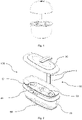
- Fig. 4 shows the mounting system component 1 with its main components in an exploded view.
- a PCB element holder 2 is configured to hold a PCB element 22 provided with a connector on each of its ends.
- a reinforcing means 213 is intended to be attached to a coupling element 21 to increase its stiffness.
- the PCB element holder 2 with the attached PCB element 22 and the reinforcing means 213 form a component to be inserted in a housing 4.
- the housing 4 is to be covered by a cover 3, preferably in a form-fitting manner.
- On one end of the housing 4 a recess 42 is formed. In the recess 42 the connector of the PCB element 22 and the coupling element 21 of the PCB element holder 2 (not shown) are arranged.
- the recess 42 of the mounting system component 1 is to be coupled to a projection 43 of another mounting system component 1 to form a connection, preferably in a releasable manner. More precisely, the coupling element 21 of the PCB element holder 2 is to be coupled with a counter-coupling element 41 of the housing 4. The PCB element 22 is positioned on the side of the PCB element holder 2 facing the cover 3.
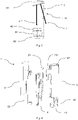
- Fig. 5 depicts the coupling element 21 and the counter-coupling element 41.
- the coupling element 21 forms part of the PCB element holder 2.
- the hookalike portions 211 of the coupling element 21 are to be inserted in the recesses 411 of the counter-coupling element 41.
- a pair of the hookalike portions 211 is to be engaged with an anchoring element 412 of the counter-coupling element 41. More precisely, upon engagement the upper section of each of the hookalike portions 211 partly encompasses the outer surface of the anchoring element 412 being substantially of a cylindrical shape.
- the reinforcing means 213, preferably a U-formed spring, is to be arranged on the circumference of the hookalike portions 211 and adjacent the regions coupling them to the PCB element holder 2 in order to increase stiffness of the hookalike portions 211, i.e. the coupling means 21. Regions forming ends of a U-formed spring are inserted in respective recesses 212 of the pair of the hookalike portions 211 of the coupling element 21.
- Fig. 6 depicts a pair of mounting system components 1 connected with each other.
- the coupling element 21 of a first mounting system component 1 is coupled with the counter-coupling element 41 of a second mounting system component 1.
- the hookalike portions 211 of the coupling element 21 are inserted in the recesses 411 of the counter-coupling element 41.
- a pair of the hookalike portions 211 is engaged with the anchoring element 412 of the counter-coupling element 41. More precisely, the upper section of each of the hookalike portions 211 partly encompasses the outer surface of the anchoring element 412.
- the reinforcing means 213 is arranged on the circumference of the hookalike portions 211 and adjacent the regions coupling them to the PCB element holder 2. Thereby, the connection between the neighbouring mounting system components 1 stiffens and provides more security with increased height of the mounting system 10 supporting the lighting assembly 20.
- Fig. 7 shows a mounting system component 1' according to another embodiment of the invention.
- This mounting system component 1' comprising an opening O is intended for lighting plants grown in the hydroponic system 100. That being said, it provides further lighting to that provided by the lighting assembly 20. This is important as with fully developed or grown plants almost no light comes to the plants from the side. Opening O in the cover 3' can be covered with a transparent lid.
- the PCB element of this embodiment comprises not only electrical connections (leads) for power supply of the LEDs of the lighting assembly 20 but also light sources preferably in a form of LEDs. These LEDs facing the opening O provide light to the plants from the side. If housing 4 is provided with an opening it can be used in both embodiments.
Landscapes
- Life Sciences & Earth Sciences (AREA)
- Environmental Sciences (AREA)
- Biodiversity & Conservation Biology (AREA)
- Botany (AREA)
- Ecology (AREA)
- Forests & Forestry (AREA)
- Hydroponics (AREA)
Abstract
Description
- The present invention relates to a hydroponic system, more particularly to a mounting system component and a mounting system for a hydroponic system.
- Hydroponic systems are becoming ever popular. More so as since a couple of years they have been suitable also for home gardening. For the purposes of this application by home gardening is meant indoor cultivation of plants. People use home indoor gardening for various reasons: stress reduction, air purification, decoration, growing spices, microgreens, herbs and other plants which can be used for cooking. There exist advanced hydroponic systems with smart (automatic) monitoring and control of parameters affecting growth and health of plants. These parameters include but are not limited to water, light and nutrients.
- In known hydroponic systems plants grow in a substrate which in most cases are clay balls, rockwool or coconut fibres. The substrate is placed in capsules. The capsules are arranged in a plant tray. Water contained in a watering tank is supplied to the capsules by means of a pump. In order to provide sufficient light to the plants (artificial) lighting is needed. It is realized by a lighting assembly being positioned above the plant tray containing the capsules. In most cases the lighting assembly is formed by LEDs which specifically come in RGB colour combination, i.e. red, green and blue.
- It is known it the art to support the lighting assembly by means of a pillar or a column constituted of so called height modules (mounting system components). These modules are connected to each other successively as the plant grows and goes through different growth phases. Consequently, height of the lighting assembly gets bigger. The pillar can be positioned centrally with relation to the plant tray.
- This has the drawback that not the whole plant tray can be used for arranging capsules and growing plants.
- The solution is to position the pillar outside of the plant tray - on its side or a circumference. That being said, also the lighting assembly is now supported from the side. The lighting assembly can be quite big and heavy as it contains several LEDs and electronic components (control unit etc.). In case of increased height (many height modules connected) the lighting assembly and the pillar can lean to the side. This means the plants don't get enough light for growth. In the worst case stability of the whole system is jeopardized to the extent it can overturn and make water leak from the system. The consequences can be quite severe - a flooded surface where the hydroponic system is positioned, damage to the plant(s) and/or the system.
- It is an object of the present invention to overcome the above-mentioned shortcomings of the prior art and particularly to improve a mounting system component and a mounting system for a hydroponic system. The mounting system component and the mounting system should also ensure efficient, safe and comfortable use of the hydroponic system.
- The object is achieved by the mounting system component according to the features of
claim 1 and the mounting system according to the features of claim 14. - Advantageous embodiments that can be implemented by themselves or in combination are described in dependent claims.
- The invention relates to a mounting system component for a hydroponic system comprising:
- a PCB element,
- a PCB element holder configured to receive the PCB element,
- a cover,
- a housing configured to receive the PCB element holder with the PCB element, characterised in that the mounting system component comprises a coupling element and a counter-coupling element configured to establish a releasable connection.
- The mounting system component according to the invention provides the following advantages:
- stiffer (more firm) connection between the mounting system components,
- compact integration of a mounting system and a electrical connection,
- no need for a force-fitting or material engagement (screwing, glueing or welding) which provides for a quicker assembly and lower costs of production,
- an audible signal (»click«) confirming the connection between the mounting system components is stable and firm,
- easy combination of ordinary mounting system components and mounting system components provided with lighting.
- Further to above advantages the mounting system comprising the mounting system components according to the invention is advantageous as it provides
- more space for capsules and growing plants (arrangement outside of a plant tray on the side of the base).
- According to one preferred embodiment, the coupling element forms part of the PCB element holder.
- In a preferred embodiment, the counter-coupling element forms part of the housing.
- In an advantageous solution, the coupling element is provided with a reinforcing means. In this way, a stiffer (more firm) connection between the mounting system components can be made.
- Optionally, the reinforcing means is a U-formed spring, preferably made of metal.
- In an advantageous solution, the coupling element is integral with the PCB element holder. The effect is that no attaching means is needed and the production costs can be reduced.
- Advantageously, the counter-coupling element comprises at least one recess and an anchoring element. This provides for a compact connection between the components.
- Optionally, the coupling element comprises at least one hookalike portion. This portion is intended to engage with the anchoring element to make a connection.
- The PCB element can comprise at least one electrical connector to establish an electric connection for a power supply to the lighting assembly.
- According to another embodiment of the invention, the cover comprises at least one opening. The effect is that the mounting system component can be configured to provide light for the plants.
- Typically, the PCB element comprises at least one light source, preferably facing the opening.
- Advantageously, the light sources are of different colour. Thus, all combinations of basic light components of red, green and blue can be generated.
- Preferably, the light source is a LED. In this way power consumption can be reduced.
- According to one preferred embodiment, mounting system comprises at least one mounting system component comprising a cover and/or at least one mounting system component comprising a cover with an opening. Combinations of the mounting system components are optional. Thus, all the embodiments can be combined.
- According to one embodiment, hydroponic system comprises a watering tank, a plant tray, a lighting assembly and a mounting system comprising the mounting system components.
- A PCB (printed circuit board) for the purposes of this application should be construed as a board mechanically supporting and electrically connecting electrical or electronic components using conductive tracks.
- Components (in this case preferably LEDs) are generally soldered onto the PCB to both electrically connect and mechanically fasten them to it.
- A PCB element should be interpreted as an element comprising a PCB.
- All aspects of the invention outlined in the present document may be arbitrarly combined. In particular, features of the claims my be combined with one another in an arbitrary manner.
-
-
Fig. 1 is a isometric view of a hydroponic system of prior art -
Fig. 2 is a isometric view of the hydroponic system comprising the mounting system components and the mounting system according the invention -
Fig. 3 is a side view of the hydroponic system comprising the mounting system components and the mounting system according the invention -
Fig. 4 is an exploded view of the mounting system component -
Fig. 5 is a isometric view of the coupling element and the counter-coupling element of the mounting system component -
Fig. 6 is a plan view of the connected mounting system components -
Fig. 7 is a isometric view of the mounting system component according to another embodiment of the invention -
Fig. 1 depicts a hydroponic appliance that forms part of the prior art. A lighting system including several LED lamps is provided in the upper part of the appliance. The lighting system is supported by a central pillar comprised of at least one supporting or height module. The lower part of the pillar is integrated in a plant tray in which capsules for growing plants are arranged. The plant tray is placed on a watering tank which includes a pump unit for pumping water (not shown) from the tank to the plant tray. The capsules contain substrate (for instance rockwool) in which plants can grow. Water which can contain nutrients (fertilizers), for instance nitrogen, phosphorus, potassium, keeps the substrate wet. The pillar is positioned centrally with regard to the plant tray. -
Fig. 2 shows ahydroponic system 100 comprising mountingsystem components 1 forming a mountingsystem 10 according to the invention. Thesystem 100 is placed on abase 60. Thebase 60 comprises a drive (not shown) including a electric motor. A coupling is provided for transferring movement and torque from the drive to a pumping unit having a pump (not shown) and being arranged in a wateringtank 30. The wateringtank 30 for holding water is positioned on thebase 60. Water is pumped from the wateringtank 30 to acapsule holder 50 which can be integral with aplant tray 40. Thecapsule holder 50 supports capsules C comprising substrate in which a seed is placed (first stage of plant growth). Alighting assembly 20 is supported by the mountingsystem 10. - The mounting
system 10 and itsmounting system components 1 provide power for thelighting assembly 20 comprising lights sources, preferably LEDs. Power is transmitted by means of PCB elements 22 (as seen inFig. 4 ) connected to each other enabling electrical connection. LEDs are preferably red, blue and green LEDs or any combination thereof. Electrical cable (not shown) is provided for connecting thehydroponic system 100 to mains. -
Fig. 3 depicts thehydroponic system 100 in a side view. The mountingsystem 10 is arranged outside of theplant tray 40 on the side or a circumference thereof and of thebase 60. The first mounting system component 1 (as seen from the bottom) is coupled to the corresponding part on thebase 60. The lastmounting system component 1 is coupled to the corresponding part on thelighting assembly 20. The mountingsystem components 1 are connected in order to make the mountingsystem 10 higher (longer) thereby raising thelighting assembly 20 and adapting it to the growth of the plants. - The watering
tank 30 is positioned on thebase 60. Shown are two different situations (represented by arrows). In the first one the mountingsystem 10 constituted of mountingsystem components 1 is not able to support thelighting assembly 20 properly. Therefore, the mountingsystem 10 and thelighting assembly 20 are inclined (not shown). The result is light L' directed substantially away from theplant tray 40. This is certainly an unwanted situation that should be avoided at all cost. With mountingsystem components 1 according to the invention this problem is solved. Namely, they provide a greater stiffness of the mountingsystem 10 as a whole so that it remains substantially perpendicular to a plane of theplant tray 40. Thus, in the second situation light L is directed directly on theplant tray 40. -
Fig. 4 shows the mountingsystem component 1 with its main components in an exploded view. - A
PCB element holder 2 is configured to hold aPCB element 22 provided with a connector on each of its ends. A reinforcingmeans 213 is intended to be attached to acoupling element 21 to increase its stiffness. ThePCB element holder 2 with the attachedPCB element 22 and the reinforcing means 213 form a component to be inserted in ahousing 4. Thehousing 4 is to be covered by acover 3, preferably in a form-fitting manner. On one end of the housing 4 arecess 42 is formed. In therecess 42 the connector of thePCB element 22 and thecoupling element 21 of the PCB element holder 2 (not shown) are arranged. Therecess 42 of the mountingsystem component 1 is to be coupled to aprojection 43 of another mountingsystem component 1 to form a connection, preferably in a releasable manner. More precisely, thecoupling element 21 of thePCB element holder 2 is to be coupled with acounter-coupling element 41 of thehousing 4. ThePCB element 22 is positioned on the side of thePCB element holder 2 facing thecover 3. -
Fig. 5 depicts thecoupling element 21 and thecounter-coupling element 41. Thecoupling element 21 forms part of thePCB element holder 2. Thehookalike portions 211 of thecoupling element 21 are to be inserted in therecesses 411 of thecounter-coupling element 41. A pair of thehookalike portions 211 is to be engaged with ananchoring element 412 of thecounter-coupling element 41. More precisely, upon engagement the upper section of each of thehookalike portions 211 partly encompasses the outer surface of theanchoring element 412 being substantially of a cylindrical shape. The reinforcing means 213, preferably a U-formed spring, is to be arranged on the circumference of thehookalike portions 211 and adjacent the regions coupling them to thePCB element holder 2 in order to increase stiffness of thehookalike portions 211, i.e. the coupling means 21. Regions forming ends of a U-formed spring are inserted inrespective recesses 212 of the pair of thehookalike portions 211 of thecoupling element 21. Upon coupling thecoupling element 21 to thecounter-coupling element 41hookalike portions 211 move past the anchoringelement 412 thereby generating an audible signal confirming a safe connection is established. -
Fig. 6 depicts a pair of mountingsystem components 1 connected with each other. Thecoupling element 21 of a firstmounting system component 1 is coupled with thecounter-coupling element 41 of a secondmounting system component 1. Thehookalike portions 211 of thecoupling element 21 are inserted in therecesses 411 of thecounter-coupling element 41. A pair of thehookalike portions 211 is engaged with the anchoringelement 412 of thecounter-coupling element 41. More precisely, the upper section of each of thehookalike portions 211 partly encompasses the outer surface of theanchoring element 412. The reinforcing means 213 is arranged on the circumference of thehookalike portions 211 and adjacent the regions coupling them to thePCB element holder 2. Thereby, the connection between the neighbouring mountingsystem components 1 stiffens and provides more security with increased height of the mountingsystem 10 supporting thelighting assembly 20. -
Fig. 7 shows a mounting system component 1' according to another embodiment of the invention. This mounting system component 1' comprising an opening O is intended for lighting plants grown in thehydroponic system 100. That being said, it provides further lighting to that provided by thelighting assembly 20. This is important as with fully developed or grown plants almost no light comes to the plants from the side. Opening O in the cover 3' can be covered with a transparent lid. The PCB element of this embodiment comprises not only electrical connections (leads) for power supply of the LEDs of thelighting assembly 20 but also light sources preferably in a form of LEDs. These LEDs facing the opening O provide light to the plants from the side. Ifhousing 4 is provided with an opening it can be used in both embodiments. -
- 1, 1' mounting system component
- 2 PCB element holder
- 3, 3' cover
- 4 housing
- 10 mounting system
- 20 lighting assembly
- 21 coupling element
- 22 PCB element
- 30 watering tank
- 40 plant tray
- 41 counter-coupling element
- 42 recess
- 43 projection
- 50 capsule holder
- 60 base
- 100 hydroponic system
- 211 hookalike portions
- 213 reinforcing means
- 411 recess
- 412 anchoring element
- C capsule
- L, L' light
- O opening
Claims (15)
- Mounting system component (1) for a hydroponic system (100) comprising:- a PCB element (22),- a PCB element holder (2) configured to receive the PCB element (22),- a cover (3),- a housing (4) configured to receive the PCB element holder (2) with the PCB element (22),characterised in that the mounting system component (1) comprises a coupling element (21) and a counter-coupling element (41) configured to establish a releasable connection.
- Mounting system component (1) according to claim 1, characterised in that the coupling element (21) forms part of the PCB element holder (2).
- Mounting system component (1) according to claim 1 or claim 2, characterised in that the counter-coupling element (41) forms part of the housing (4).
- Mounting system component (1) according to any of the preceding claims, characterised in that the coupling element (21) is provided with a reinforcing means (213).
- Mounting system component (1) according to claim 4, characterised in that the reinforcing means (213) is a U-formed spring.
- Mounting system component (1) according to any of the preceding claims, characterised in that the coupling element (21) is integral with the PCB element holder (2).
- Mounting system component (1) according to any of the preceding claims, characterised in that the counter-coupling element (41) comprises at least one recess (411) and an anchoring element (412).
- Mounting system component (1) according to any of the preceding claims, characterised in that the coupling element (21) comprises at least one hookalike portion (211).
- Mounting system component (1) according to any of the preceding claims, characterised in that the PCB element (22) comprises at least one electrical connector.
- Mounting system component according to any of the preceding claims, characterised in that the cover (3) comprises at least one opening (O).
- Mounting system component (1') according to claim 10, characterised in that the PCB element (22) comprises at least one light source.
- Mounting system component (1') according to claim 11, characterised in that the light sources are of different colour.
- Mounting system component (1') according to claims 11 - 12, characterised in that the light source is a LED.
- Mounting system (10) comprising at least one mounting system component (1) according to claims 1-9 and/or at least one mounting system component (1') according to claims 10-13.
- Hydroponic system (100) comprising:- a watering tank (30),- a plant tray (40),- a lighting assembly (20), and- a mounting system (10) according to claim 14.
Priority Applications (2)
| Application Number | Priority Date | Filing Date | Title |
|---|---|---|---|
| EP21175300.9A EP4091439A1 (en) | 2021-05-21 | 2021-05-21 | Mounting system for a hydroponic system |
| CN202210549431.8A CN115362925A (en) | 2021-05-21 | 2022-05-20 | Mounting system for hydroponic systems |
Applications Claiming Priority (1)
| Application Number | Priority Date | Filing Date | Title |
|---|---|---|---|
| EP21175300.9A EP4091439A1 (en) | 2021-05-21 | 2021-05-21 | Mounting system for a hydroponic system |
Publications (1)
| Publication Number | Publication Date |
|---|---|
| EP4091439A1 true EP4091439A1 (en) | 2022-11-23 |
Family
ID=76059756
Family Applications (1)
| Application Number | Title | Priority Date | Filing Date |
|---|---|---|---|
| EP21175300.9A Pending EP4091439A1 (en) | 2021-05-21 | 2021-05-21 | Mounting system for a hydroponic system |
Country Status (2)
| Country | Link |
|---|---|
| EP (1) | EP4091439A1 (en) |
| CN (1) | CN115362925A (en) |
Citations (2)
| Publication number | Priority date | Publication date | Assignee | Title |
|---|---|---|---|---|
| CN209151880U (en) * | 2018-10-31 | 2019-07-26 | 英特卡机电(惠州)有限公司 | A kind of hydroponic plant grower |
| US20200232613A1 (en) * | 2019-01-23 | 2020-07-23 | Lighting Solutions Group Llc | Assembly for improved installation and method of use |
-
2021
- 2021-05-21 EP EP21175300.9A patent/EP4091439A1/en active Pending
-
2022
- 2022-05-20 CN CN202210549431.8A patent/CN115362925A/en active Pending
Patent Citations (2)
| Publication number | Priority date | Publication date | Assignee | Title |
|---|---|---|---|---|
| CN209151880U (en) * | 2018-10-31 | 2019-07-26 | 英特卡机电(惠州)有限公司 | A kind of hydroponic plant grower |
| US20200232613A1 (en) * | 2019-01-23 | 2020-07-23 | Lighting Solutions Group Llc | Assembly for improved installation and method of use |
Also Published As
| Publication number | Publication date |
|---|---|
| CN115362925A (en) | 2022-11-22 |
Similar Documents
| Publication | Publication Date | Title |
|---|---|---|
| US9832941B2 (en) | Hydroponic cultivation apparatus | |
| CN102667327B (en) | Holder assembly | |
| KR101333809B1 (en) | Led socket assembly | |
| KR20110065406A (en) | Solid state lighting system | |
| US9307598B2 (en) | LED lighting device with replaceable driver-control module | |
| US20200232613A1 (en) | Assembly for improved installation and method of use | |
| EP4091439A1 (en) | Mounting system for a hydroponic system | |
| KR20130053376A (en) | Led socket assembly | |
| US20080144310A1 (en) | Rechargeable lighting apparatus | |
| KR20120060096A (en) | flowerpot device | |
| US11944050B2 (en) | Fixtureless lamp | |
| US20060062020A1 (en) | Structure improvement for christmas bulb socket | |
| CN221429630U (en) | Planting bin and corresponding planting system | |
| CN120240173A (en) | Lighting devices for plant cultivation | |
| CN102379222A (en) | a flower pot lamp | |
| US20200284404A1 (en) | Hub based lighting system | |
| KR101322003B1 (en) | The Multi-Level Hydroponic System using Acrylic panel | |
| KR102793157B1 (en) | lamp for dragon fruits growth | |
| EP3382260A1 (en) | Plant growth lamp module and plant growth lamp using the same | |
| EP4091438A1 (en) | Optical element and mount system for a hydroponic system, and hydroponic system therewith | |
| CN212644526U (en) | Plant lamp fixing device | |
| WO2019234818A1 (en) | Artificial cultivation device | |
| US11686424B2 (en) | Apparatus having plurality of stands | |
| CN221035480U (en) | Lighting device | |
| CN117356300A (en) | A planting warehouse and corresponding planting system |
Legal Events
| Date | Code | Title | Description |
|---|---|---|---|
| PUAI | Public reference made under article 153(3) epc to a published international application that has entered the european phase |
Free format text: ORIGINAL CODE: 0009012 |
|
| STAA | Information on the status of an ep patent application or granted ep patent |
Free format text: STATUS: THE APPLICATION HAS BEEN PUBLISHED |
|
| AK | Designated contracting states |
Kind code of ref document: A1 Designated state(s): AL AT BE BG CH CY CZ DE DK EE ES FI FR GB GR HR HU IE IS IT LI LT LU LV MC MK MT NL NO PL PT RO RS SE SI SK SM TR |
|
| STAA | Information on the status of an ep patent application or granted ep patent |
Free format text: STATUS: REQUEST FOR EXAMINATION WAS MADE |
|
| 17P | Request for examination filed |
Effective date: 20230523 |
|
| RBV | Designated contracting states (corrected) |
Designated state(s): AL AT BE BG CH CY CZ DE DK EE ES FI FR GB GR HR HU IE IS IT LI LT LU LV MC MK MT NL NO PL PT RO RS SE SI SK SM TR |