EP4091438A1 - Optical element and mount system for a hydroponic system, and hydroponic system therewith - Google Patents
Optical element and mount system for a hydroponic system, and hydroponic system therewith Download PDFInfo
- Publication number
- EP4091438A1 EP4091438A1 EP21175298.5A EP21175298A EP4091438A1 EP 4091438 A1 EP4091438 A1 EP 4091438A1 EP 21175298 A EP21175298 A EP 21175298A EP 4091438 A1 EP4091438 A1 EP 4091438A1
- Authority
- EP
- European Patent Office
- Prior art keywords
- optical element
- mount system
- housing component
- component
- light
- Prior art date
- Legal status (The legal status is an assumption and is not a legal conclusion. Google has not performed a legal analysis and makes no representation as to the accuracy of the status listed.)
- Pending
Links
- 230000003287 optical effect Effects 0.000 title claims abstract description 45
- 241000196324 Embryophyta Species 0.000 claims description 45
- 240000003380 Passiflora rubra Species 0.000 claims description 8
- 239000002775 capsule Substances 0.000 description 9
- 238000005286 illumination Methods 0.000 description 4
- 239000002689 soil Substances 0.000 description 4
- 239000000758 substrate Substances 0.000 description 4
- XLYOFNOQVPJJNP-UHFFFAOYSA-N water Substances O XLYOFNOQVPJJNP-UHFFFAOYSA-N 0.000 description 4
- 230000008878 coupling Effects 0.000 description 2
- 238000010168 coupling process Methods 0.000 description 2
- 238000005859 coupling reaction Methods 0.000 description 2
- 239000004927 clay Substances 0.000 description 1
- 238000010411 cooking Methods 0.000 description 1
- 238000005034 decoration Methods 0.000 description 1
- 230000001419 dependent effect Effects 0.000 description 1
- 238000010413 gardening Methods 0.000 description 1
- 238000003306 harvesting Methods 0.000 description 1
- 239000004615 ingredient Substances 0.000 description 1
- 238000004519 manufacturing process Methods 0.000 description 1
- 238000000034 method Methods 0.000 description 1
- 239000011490 mineral wool Substances 0.000 description 1
- 238000012544 monitoring process Methods 0.000 description 1
- 230000000050 nutritive effect Effects 0.000 description 1
- 230000029553 photosynthesis Effects 0.000 description 1
- 238000010672 photosynthesis Methods 0.000 description 1
- 238000005086 pumping Methods 0.000 description 1
- 235000013599 spices Nutrition 0.000 description 1
- 239000000126 substance Substances 0.000 description 1
Images

Classifications
-
- A—HUMAN NECESSITIES
- A01—AGRICULTURE; FORESTRY; ANIMAL HUSBANDRY; HUNTING; TRAPPING; FISHING
- A01G—HORTICULTURE; CULTIVATION OF VEGETABLES, FLOWERS, RICE, FRUIT, VINES, HOPS OR SEAWEED; FORESTRY; WATERING
- A01G7/00—Botany in general
- A01G7/04—Electric or magnetic or acoustic treatment of plants for promoting growth
- A01G7/045—Electric or magnetic or acoustic treatment of plants for promoting growth with electric lighting
-
- A—HUMAN NECESSITIES
- A01—AGRICULTURE; FORESTRY; ANIMAL HUSBANDRY; HUNTING; TRAPPING; FISHING
- A01G—HORTICULTURE; CULTIVATION OF VEGETABLES, FLOWERS, RICE, FRUIT, VINES, HOPS OR SEAWEED; FORESTRY; WATERING
- A01G9/00—Cultivation in receptacles, forcing-frames or greenhouses; Edging for beds, lawn or the like
- A01G9/24—Devices or systems for heating, ventilating, regulating temperature, illuminating, or watering, in greenhouses, forcing-frames, or the like
- A01G9/249—Lighting means
-
- A—HUMAN NECESSITIES
- A01—AGRICULTURE; FORESTRY; ANIMAL HUSBANDRY; HUNTING; TRAPPING; FISHING
- A01G—HORTICULTURE; CULTIVATION OF VEGETABLES, FLOWERS, RICE, FRUIT, VINES, HOPS OR SEAWEED; FORESTRY; WATERING
- A01G31/00—Soilless cultivation, e.g. hydroponics
- A01G31/02—Special apparatus therefor
-
- A—HUMAN NECESSITIES
- A01—AGRICULTURE; FORESTRY; ANIMAL HUSBANDRY; HUNTING; TRAPPING; FISHING
- A01G—HORTICULTURE; CULTIVATION OF VEGETABLES, FLOWERS, RICE, FRUIT, VINES, HOPS OR SEAWEED; FORESTRY; WATERING
- A01G31/00—Soilless cultivation, e.g. hydroponics
- A01G31/02—Special apparatus therefor
- A01G31/06—Hydroponic culture on racks or in stacked containers
-
- G—PHYSICS
- G02—OPTICS
- G02B—OPTICAL ELEMENTS, SYSTEMS OR APPARATUS
- G02B3/00—Simple or compound lenses
-
- G—PHYSICS
- G02—OPTICS
- G02B—OPTICAL ELEMENTS, SYSTEMS OR APPARATUS
- G02B6/00—Light guides; Structural details of arrangements comprising light guides and other optical elements, e.g. couplings
-
- Y—GENERAL TAGGING OF NEW TECHNOLOGICAL DEVELOPMENTS; GENERAL TAGGING OF CROSS-SECTIONAL TECHNOLOGIES SPANNING OVER SEVERAL SECTIONS OF THE IPC; TECHNICAL SUBJECTS COVERED BY FORMER USPC CROSS-REFERENCE ART COLLECTIONS [XRACs] AND DIGESTS
- Y02—TECHNOLOGIES OR APPLICATIONS FOR MITIGATION OR ADAPTATION AGAINST CLIMATE CHANGE
- Y02P—CLIMATE CHANGE MITIGATION TECHNOLOGIES IN THE PRODUCTION OR PROCESSING OF GOODS
- Y02P60/00—Technologies relating to agriculture, livestock or agroalimentary industries
- Y02P60/20—Reduction of greenhouse gas [GHG] emissions in agriculture, e.g. CO2
- Y02P60/21—Dinitrogen oxide [N2O], e.g. using aquaponics, hydroponics or efficiency measures
Definitions
- the present invention concerns an optical element for a hydroponic system.
- the invention further concerns a mount system component of a hydroponic system, and a hydroponic system.
- the respective plant(s) grow in soil or in a substrate (such as a medium containing an expanded clay aggregate and/or rock wool, for instance) held in a plant tray which is placed or placeable in or on a watering tank containing water.
- a substrate such as a medium containing an expanded clay aggregate and/or rock wool, for instance
- the soil or substrate may be contained in respective capsules which may be held in a capsule holder placed (preferably detachably) in the plant tray.
- a pump unit is typically configured to pump water (which may be enriched with nutritive substances) from the watering tank into the plant tray, thus automatically facilitating care of the respective plant(s).
- the watering tank may have an allocated position on a base station of the hydroponic system. In these cases, to improve convenience of the system, e.g., to simplify care and harvest of the plants, the watering tank may advantageously be adapted to be taken off the base station.
- a top lamp may be held, by a mount system, above the respective plant(s), so as to ensure a sufficient photosynthesis thereof even if the hydroponic system is placed at a location not adequately illuminated by sun light.
- the top lamp and a drive unit (such as an electric motor) for the pump unit are connectable, via a common electrical connection, to an electric supply network.
- An optical element according to the present invention is devised for or belongs to a hydroponic system comprising a top lamp and a mount system holding the top lamp.
- the optical element comprises at least one lightguide portion configured to be (preferably detachably) placed, through one or more openings/s in a housing component of the mount system, on or over one or more light source/s (such as light-emitting diode/s) mounted, so as to face the one or more openings, on a printed circuit board arranged within the housing component.
- the optical element in particular the lightguide portion thereof
- on or over in the expression “placed on or over” in this document does not necessarily refer to a vertical orientation, but is to be understood with respect to a direction in which the lightguide portion is moved, when placed, towards the light source/s, which direction is considered as from above the printed circuit board downwards.
- the lightguide portion may have direct contact with the light source/s or may be arranged with a positive distance from the light source/s.
- the lightguide portion may be put over the light source/s, so as to also at least partially surround it/them laterally.
- the lightguide portion may contact the printed circuit board and/or at least one of the one or more light source/s.
- the mount system may comprise one or more mount system components, which may be configured to be combined with each other such as to modify a height at which the top lamp is respectively positioned, in a designated orientation of utilisation of the hydroponic system, above a plant tray of the hydroponic system.
- the housing component may form part of one of such mount system components.
- the lightguide portion of an optical element according to the present invention is further configured to focus, when arranged in said position, light of the one or more light source/s to an exterior environment of the housing component.
- the lightguide portion may be configured to focus said light into a predetermined angular range (about the mount system).
- angular range covers a cylinder sector with a central angle (at the one or more light source/s) of at most 180° or at most 160°, and/or of at least 105°, at least 120° or at least 135°.
- the optical element according to the present invention thus allows the mount system to advantageously illuminate, with the one or more light sources arranged within the housing component and through the at least one opening therein, plants eventually growing in the plant tray of the hydroponic system.
- the illumination may be made further (simultaneously) to that provided by the top lamp or (selectively) alternatively to that of the top lamp, such as depending on a respective growing stage of the plant/s.
- an advantageous homogeneous light distribution to the respective plants may be achieved, which may stimulate growth and health of the plants.
- due to the position of the light source/s and the focussing of their light a loss of light and an undesired illumination of an environment of the hydroponic system can be prevented.
- a mount system component is a component of a mount system holding a top lamp of a hydroponic system.
- the mount system component may form the entire mount system, whereas in cases of various combinable components together forming the mount system, said mount system component may be one of these various components.
- the mount system component may be configured to be combined (such as by means of a screwing system and/or by means of a plug system) with at least one further component of the mount system, such as to alter a distance at which the top lamp is placed from a plant tray of the hydroponic system (which altering may be advantageous to adapt the position of the top lamp to a respectively current growing stage of the plant/s).
- the mount system component may itself be prolongable, such as by means of a telescope mechanism the mount system component may include.
- the mount system component comprises a housing component with at least one opening, a printed circuit board arranged within the housing component and having mounted thereon one or more light sources (such as light-emitting diode/s) facing the at least one opening, and a matching optical element according an embodiment of the present invention.
- the lightguide portion of the optical element thus is adapted to be placed, through the one or more opening/s, on or over the one or more light source/s, and to focus light of the one or more light source/s to an exterior environment of the housing component.
- a hydroponic system comprises a watering tank, a plant tray, a top lamp configured to illuminate the plant tray, and a mount system holding the top lamp.
- the mount system comprises at least one mount system component according to an embodiment of the present invention.
- the lightguide portion of the optical element is preferably configured to focus light of the one or more light sources towards a region above the plant tray.
- the exterior environment to which the lightguide portion of the optical element is configured to focus light of the one or more light source may preferably include an angular range covering an area of at least 80% or at least 90% of an extension of the plant tray.
- the mount system (in particular said mount system component comprising the optical element) is arranged laterally to the plant tray, i.e., at a side thereof.
- the hydroponic system may further comprise a pump unit configured to pump water from the watering tank to the plant tray, and/or a capsule holder with at least one capsule holder opening configured to receive a respective capsule containing a soil or substrate for at least one respective plant rooting therein.
- the hydroponic system may comprise an electrical connection for connecting the top lamp and/or - in respective embodiments - a drive unit for the pump unit to an electric supply network.
- Such electrical connection may be fixed to the watering tank.
- the electrical connection may be fixed to the base station.
- the at least one lightguide portion of the optical element is monolithic.
- the at least one lightguide portion of the optical element comprises at least one batwing lens.
- batwing lens may comprise a respective paraboloidal inner focus region which may preferably be positioned on or over a respective one of the light source/s.
- the at least one lightguide portion of the optical element may comprise at least one bulbous lens; such lens may thus have an essentially round bodied shape. Preferably, it may have a paraboloidal focus.
- Such bulbous lens may provide for an advantageous direction of light rays emitted by the respective light source the bulbous lens is placed on or over.
- the at least one bulbous lens may preferably be entirely or at least partially framed by a portion of the housing component.
- such bulbous lens may close a respective opening in the housing component and/or extend therethrough.
- the printed circuit board may be invisible from outside the mount system.
- the at least one bulbous lens may preferably have a recess configured to receive a respective one of the one or more light source/s when the lightguide portion is placed thereon or thereover.
- the optical element further comprises a clip portion configured to detachably fix the at least one lightguide portion to the housing component.
- the clip portion may be separate or separable from the at least one lightguide portion; in this case the clip portion and the lightguide portion thus are at least two different elements.
- at least a part of the clip portion may be permanently connected to the lightguide portion, which thus both form part of a single common piece.
- the lightguide portion and said part may be monolithic.
- the clip portion may comprise one or more snap fit/s and/or one or more magnets for detachable fixation of the lightguide portion to the housing component.
- a hydroponic system 100 according to an exemplary embodiment of the present invention is shown in a perspective view and in a designated orientation of utilisation.
- the hydroponic system 100 comprises a plant tray 40 holding a capsule holder 50 with openings C for receiving respective plant capsules (with soil or substrate, and preferably with at least one plant and/or seed contained therein), a watering tank 30 and a base station 60.
- the plant tray 40 is (advantageously removably) placed on the watering tank 30 which is positioned, at a designated position thereof, on the base station 60.
- the base station 60 preferably comprises a drive unit (not shown) configured to drive - via a coupling (not shown) - a pump unit (not shown) for pumping water from the watering tank 30 to the plant tray 40.
- the base station 60 is connectable, via an electric connection 61, to an electric supply network (not shown).
- the watering tank itself may comprise a drive unit for driving a pump unit, and an electric connection for providing the drive unit with electric energy.
- the hydroponic system 100 further comprises a top lamp 20 held by a mount system 10 and configured to illuminate from above plants (not shown) growing in the plant tray 40.
- the mount system 10 in the present case may be fixed to the base station 60 and/or to the watering tank 30. Via the mount system 10, one or more illuminant/s of the lamp 20 is/are preferably connected to the electric connection 61.
- the top lamp 20 may comprise a battery and/or accumulator for providing the illuminant/s with electric energy.
- the mount system 10 comprises a mount system component 11 according to an exemplary embodiment of the present invention.
- the mount system 10 comprises at least one further component 14.
- mount system 10 may be configured as a plug system, with the mount system component 11 and the at least one further component 14 configured to be plugged together so as to vary a height at which the top lamp 20 is held above the plant tray 40.
- the mount system 10 may comprise at least one telescopic element, or may be itself (on the whole) extendible.
- the mount system component 11 shown in Figure 1a comprises a housing component 4 forming a housing structure of the mount system component and having an opening O in which a printed circuit board holding at least one light source (such as at least one light-emitting diode (LED)) is arranged (not visible in Figure 1a ). Electric connection wires (not shown) of the printed circuit board preferably run through the housing component 4, which in particular may be at least partially hollow.
- a light source such as at least one light-emitting diode (LED)
- Electric connection wires (not shown) of the printed circuit board preferably run through the housing component 4, which in particular may be at least partially hollow.
- the mount system component 11 further includes an optical element 1 according to an exemplary embodiment of the present invention.
- the optical element 1 comprises a lightguide portion 2 and a clip portion 3 fastening the lightguide portion 2 to the housing component 4. Thereby, the opening O is closed.
- the optical element 1 preferably can be selectively clipped on or off the housing structure 4.
- the clip portion 3 itself may be fixable/ fixed to the housing component 4 by means of one or more snap fit/s and/or one or more magnet/s.
- the optical element 1 is fastened to the housing component 4 so as to face the plant tray.
- the optical element 1 is configured to focus light originating from the at least one light source in the interior of the housing component 4 to an exterior environment of the housing component and, therewith, towards plants eventually growing in the plant tray 40, whereas the light is inhibited to propagate at directions away from the plants.
- light of the one or more light source/s is kept away from an interior of the mount system component.
- loss of light inside the housing component 4 is prevented, the light distribution is amplified towards a place where it is needed, and disturbing lateral or rearward light is obviated.
- the light tray 40 and a (plug) end of the mount system component 11 are shown from above (with respect to the designated orientation of utilisation of the hydroponic system).
- the light L originating from one or more light source/s (not visible in Figure 1b ) in the interior of the housing component 4 is focussed, by the optical element 1, into an angular range W of an environment of the mount system component 11 (and therewith, of the mount system 10 shown in Figure 1a ).
- Figure 2a shows a sectional view of the mount system component 11, wherein the section is taken in a longitudinal direction thereof. It provides an insight into the housing component 4 with its opening O in which the printed circuit board 12 mounting - presently four - light sources 13 is arranged.
- the light sources at least one of which may be an LED
- the light sources may be configured to provide red light and/or one or more of the light sources may be configured to provide blue light.
- the optical element 1 comprises a lightguide portion 2 and a clip portion 3 which in this case is an element separate from the lightguide portion 2.
- the clip portion 3 detachably fixes the lightguide portion 2 to the housing component 4.
- the lightguide portion 2 of the exemplary embodiment shown comprises four batwing lenses 2a with a respective paraboloidal inner focus F.
- the lightguide portion 2 of the optical element 1 has been placed, through the opening O, over the light sources 13.
- the batwing lenses 2a with their respective paraboloidal inner focuses F each are put over a respective one of the light sources.
- an advantageous light distribution can be achieved, as by the batwing lenses 2a, light in particular is directed laterally, towards an edge of the focus.
- Figure 2b shows the lightguide portion 2 with its batwing lenses 2a and their respective paraboloidal inner focuses F separately and in a perspective view.
- a mount system component 11' according to an alternative embodiment of the present invention is shown in a sectional view, wherein the section is taken in a longitudinal direction thereof. It provides an insight into the housing component 4' in which the printed circuit board 12' is arranged and which in this case has two openings O.
- the printed circuit board 12' mounts two light sources 13' (at least one of which may be an LED). For instance, at least one of the light sources may be configured to provide red light and/or at least one of the light sources may be configured to provide blue light.
- the optical element 1' comprises a lightguide portion 2' and a clip portion 3'.
- the clip portion 3' may be fixable/ fixed to the housing component 4' by means of one or more snap fit/s and/or one or more magnet/s (not shown).
- the clip portion 3' in this embodiment is permanently connected with the lightguide portion; lightguide portion 2' and at least a part of clip portion 3' thus form a one-piece component.
- the optical element 1' may be monolithic.
- the lightguide portion 2' of the optical element 1' shown in Figure 3a comprises two bulbous lenses 2'a each having a respective recess R at their side facing the printed circuit board 12'.
- the lightguide portion 2' has been placed on the light sources 13'.
- each of the bulbous lenses 2'a runs through a respective one of openings O, and is thus framed by a portion of the housing component 4'.
- the printed circuit board 12' is masked.
- the lightguide portion 2' is placed such that each recess R at least partially accommodates a respective one of the light sources 13'.
- the light emitted - in operation - by the light sources 13' is fully or at least almost fully fed into the lightguide portion 2' and focussed thereby to an exterior environment of the housing component 4'.
- a light loss in the interior of the housing component 4' and/or an undesired illumination of a backside of the mount system are prevented.
- the bulbous lenses 2'a with their respective (preferably paraboloidal) focus F provide for a projection of light L in front of the mount system component 11' and, therewith, an advantageous light distribution among plants eventually growing in a plant tray as that shown in Figures 1a, 1b .
- an optical element 1, 1' for a hydroponic system 100 comprising a top lamp 20 and a mount system 10 holding the top lamp 20.
- the optical element comprises at least one lightguide portion 2, 2' configured to be placed, through one or more openings/s O of a housing component 4, 4' of the mount system 10, on or over one or more light source/s 13, 13' facing the one or more openings O and being mounted on a printed circuit board 12, 12' arranged within the housing component 4, 4'.
- the lightguide portion 2, 2' is further configured to focus light of the one or more light source/s 13, 13' to an exterior environment of the housing component 4, 4'.
- mount system component 11, 11' comprising such optical element 1, 1'
- hydroponic system 100 comprising one or more such mount system component/s 11, 11'.
Landscapes
- Life Sciences & Earth Sciences (AREA)
- Environmental Sciences (AREA)
- Physics & Mathematics (AREA)
- General Physics & Mathematics (AREA)
- Optics & Photonics (AREA)
- Biodiversity & Conservation Biology (AREA)
- Botany (AREA)
- Ecology (AREA)
- Forests & Forestry (AREA)
- Cultivation Of Plants (AREA)
- Hydroponics (AREA)
Abstract
Description
- The present invention concerns an optical element for a hydroponic system. The invention further concerns a mount system component of a hydroponic system, and a hydroponic system.
- Indoor cultivation of plants is not only established in the field of professional economic gardening, but also popular in domestic planting for the purpose of decoration, generation of an advantageous indoor climate and/or personal production of spices or other ingredients for cooking or baking. In particular, sophisticated hydroponic systems may be used, which may facilitate automatic monitoring and control of parameters influencing the growth and health of the respective plants.
- In known hydroponic systems, the respective plant(s) grow in soil or in a substrate (such as a medium containing an expanded clay aggregate and/or rock wool, for instance) held in a plant tray which is placed or placeable in or on a watering tank containing water. In particular, the soil or substrate may be contained in respective capsules which may be held in a capsule holder placed (preferably detachably) in the plant tray.
- A pump unit is typically configured to pump water (which may be enriched with nutritive substances) from the watering tank into the plant tray, thus automatically facilitating care of the respective plant(s). The watering tank may have an allocated position on a base station of the hydroponic system. In these cases, to improve convenience of the system, e.g., to simplify care and harvest of the plants, the watering tank may advantageously be adapted to be taken off the base station.
- A top lamp may be held, by a mount system, above the respective plant(s), so as to ensure a sufficient photosynthesis thereof even if the hydroponic system is placed at a location not adequately illuminated by sun light. Preferably, the top lamp and a drive unit (such as an electric motor) for the pump unit are connectable, via a common electrical connection, to an electric supply network.
- It is an object of the present invention to provide a technique facilitating an improved hydroponic system.
- The object is achieved by an optical element according to
claim 1, by a mount system component according to claim 7 and by a hydroponic system according to claim 8. Advantageous embodiments are disclosed in the dependent claims, the description and the figures. - An optical element according to the present invention is devised for or belongs to a hydroponic system comprising a top lamp and a mount system holding the top lamp. The optical element comprises at least one lightguide portion configured to be (preferably detachably) placed, through one or more openings/s in a housing component of the mount system, on or over one or more light source/s (such as light-emitting diode/s) mounted, so as to face the one or more openings, on a printed circuit board arranged within the housing component. In particular, such placed, the optical element (in particular the lightguide portion thereof) may preferably close the one or more opening/s. For instance, it may extend through the opening/s.
- The term "on or over" in the expression "placed on or over" in this document does not necessarily refer to a vertical orientation, but is to be understood with respect to a direction in which the lightguide portion is moved, when placed, towards the light source/s, which direction is considered as from above the printed circuit board downwards.
- Such placed on or over, the lightguide portion may have direct contact with the light source/s or may be arranged with a positive distance from the light source/s. In particular, the lightguide portion may be put over the light source/s, so as to also at least partially surround it/them laterally. In particular, when placed on or over the one or more light source/s, the lightguide portion may contact the printed circuit board and/or at least one of the one or more light source/s.
- The mount system may comprise one or more mount system components, which may be configured to be combined with each other such as to modify a height at which the top lamp is respectively positioned, in a designated orientation of utilisation of the hydroponic system, above a plant tray of the hydroponic system. The housing component may form part of one of such mount system components.
- The lightguide portion of an optical element according to the present invention is further configured to focus, when arranged in said position, light of the one or more light source/s to an exterior environment of the housing component.
- In particular, the lightguide portion may be configured to focus said light into a predetermined angular range (about the mount system). Preferably, such angular range covers a cylinder sector with a central angle (at the one or more light source/s) of at most 180° or at most 160°, and/or of at least 105°, at least 120° or at least 135°.
- The optical element according to the present invention thus allows the mount system to advantageously illuminate, with the one or more light sources arranged within the housing component and through the at least one opening therein, plants eventually growing in the plant tray of the hydroponic system. Therein, the illumination may be made further (simultaneously) to that provided by the top lamp or (selectively) alternatively to that of the top lamp, such as depending on a respective growing stage of the plant/s. Thereby, an advantageous homogeneous light distribution to the respective plants may be achieved, which may stimulate growth and health of the plants. Moreover, due to the position of the light source/s and the focussing of their light, a loss of light and an undesired illumination of an environment of the hydroponic system can be prevented.
- A mount system component according to the present invention is a component of a mount system holding a top lamp of a hydroponic system. In cases of a one-piece mount system, the mount system component may form the entire mount system, whereas in cases of various combinable components together forming the mount system, said mount system component may be one of these various components. In particular, the mount system component may be configured to be combined (such as by means of a screwing system and/or by means of a plug system) with at least one further component of the mount system, such as to alter a distance at which the top lamp is placed from a plant tray of the hydroponic system (which altering may be advantageous to adapt the position of the top lamp to a respectively current growing stage of the plant/s). Additionally or alternatively, the mount system component may itself be prolongable, such as by means of a telescope mechanism the mount system component may include.
- The mount system component according to the present invention comprises a housing component with at least one opening, a printed circuit board arranged within the housing component and having mounted thereon one or more light sources (such as light-emitting diode/s) facing the at least one opening, and a matching optical element according an embodiment of the present invention. In particular, the lightguide portion of the optical element thus is adapted to be placed, through the one or more opening/s, on or over the one or more light source/s, and to focus light of the one or more light source/s to an exterior environment of the housing component.
- A hydroponic system according to the present invention comprises a watering tank, a plant tray, a top lamp configured to illuminate the plant tray, and a mount system holding the top lamp. Therein, the mount system comprises at least one mount system component according to an embodiment of the present invention.
- Therein, the lightguide portion of the optical element is preferably configured to focus light of the one or more light sources towards a region above the plant tray. In particular, the exterior environment to which the lightguide portion of the optical element is configured to focus light of the one or more light source may preferably include an angular range covering an area of at least 80% or at least 90% of an extension of the plant tray. Thereby, a particularly advantageous illumination of plants eventually held by the plant tray can be achieved.
- According to advantageous embodiments, with regard to a designated orientation of utilisation of the hydroponic system, the mount system (in particular said mount system component comprising the optical element) is arranged laterally to the plant tray, i.e., at a side thereof.
- The hydroponic system may further comprise a pump unit configured to pump water from the watering tank to the plant tray, and/or a capsule holder with at least one capsule holder opening configured to receive a respective capsule containing a soil or substrate for at least one respective plant rooting therein.
- Moreover, the hydroponic system may comprise an electrical connection for connecting the top lamp and/or - in respective embodiments - a drive unit for the pump unit to an electric supply network. Such electrical connection may be fixed to the watering tank. Alternatively or additionally, in embodiments further comprising a base station with an allocated position for the watering tank (and preferably a corresponding coupling), the electrical connection may be fixed to the base station.
- Preferably, the at least one lightguide portion of the optical element is monolithic.
- According to advantageous embodiments of the present invention, the at least one lightguide portion of the optical element comprises at least one batwing lens. Such batwing lens may comprise a respective paraboloidal inner focus region which may preferably be positioned on or over a respective one of the light source/s. Thereby, an advantageous light distribution can be achieved, as light in particular is directed laterally, towards an edge of the focus.
- Additionally or alternatively, the at least one lightguide portion of the optical element may comprise at least one bulbous lens; such lens may thus have an essentially round bodied shape. Preferably, it may have a paraboloidal focus. Such bulbous lens may provide for an advantageous direction of light rays emitted by the respective light source the bulbous lens is placed on or over.
- In such embodiments, the at least one bulbous lens may preferably be entirely or at least partially framed by a portion of the housing component. In particular, such bulbous lens may close a respective opening in the housing component and/or extend therethrough. As a consequence, the printed circuit board may be invisible from outside the mount system.
- Additionally or alternatively, the at least one bulbous lens may preferably have a recess configured to receive a respective one of the one or more light source/s when the lightguide portion is placed thereon or thereover. Thereby, a particularly advantageous focussing and a space saving arrangement can be realised.
- According to advantageous embodiments of the present invention, the optical element further comprises a clip portion configured to detachably fix the at least one lightguide portion to the housing component. The clip portion may be separate or separable from the at least one lightguide portion; in this case the clip portion and the lightguide portion thus are at least two different elements. Alternatively, at least a part of the clip portion may be permanently connected to the lightguide portion, which thus both form part of a single common piece. In particular, the lightguide portion and said part may be monolithic.
- The clip portion may comprise one or more snap fit/s and/or one or more magnets for detachable fixation of the lightguide portion to the housing component.
- In the following, preferred embodiments of the present invention are explained with respect to the accompanying drawings. As is to be understood, the various elements and components are depicted as examples only, may be facultative and/or combined in a manner different than that depicted. Reference signs for related elements are used comprehensively and not defined again for each figure.
- Shown is schematically in
- Fig. 1a:
- an exemplary embodiment of a hydroponic system according to the present invention;
- Fig. 1b:
- a portion of hydroponic system according to the present invention from above the plant tray;
- Fig. 2a:
- a mount system component according to a first exemplary embodiment of the present invention in a sectional view;
- Fig. 2b:
- the lightguide portion of the mount system component of
Figure 2a in a perspective view; - Fig. 3a:
- a mount system component according to a second exemplary embodiment of the present invention in a sectional view; and
- Fig. 3b:
- the optical element of the mount system component of
Figure 3a . - In
Figure 1a , ahydroponic system 100 according to an exemplary embodiment of the present invention is shown in a perspective view and in a designated orientation of utilisation. Thehydroponic system 100 comprises aplant tray 40 holding acapsule holder 50 with openings C for receiving respective plant capsules (with soil or substrate, and preferably with at least one plant and/or seed contained therein), a wateringtank 30 and abase station 60. - In the situation depicted, the
plant tray 40 is (advantageously removably) placed on the wateringtank 30 which is positioned, at a designated position thereof, on thebase station 60. Thebase station 60 preferably comprises a drive unit (not shown) configured to drive - via a coupling (not shown) - a pump unit (not shown) for pumping water from the wateringtank 30 to theplant tray 40. To provide the drive unit with electric energy, thebase station 60 is connectable, via anelectric connection 61, to an electric supply network (not shown). As is to be noted, according to other (not shown) embodiments on the present invention, the watering tank itself may comprise a drive unit for driving a pump unit, and an electric connection for providing the drive unit with electric energy. - The
hydroponic system 100 further comprises atop lamp 20 held by amount system 10 and configured to illuminate from above plants (not shown) growing in theplant tray 40. - Although not visible due to the perspective of
Figure 1a , themount system 10 in the present case may be fixed to thebase station 60 and/or to the wateringtank 30. Via themount system 10, one or more illuminant/s of thelamp 20 is/are preferably connected to theelectric connection 61. Alternatively or additionally, thetop lamp 20 may comprise a battery and/or accumulator for providing the illuminant/s with electric energy. - The
mount system 10 comprises amount system component 11 according to an exemplary embodiment of the present invention. Moreover, themount system 10 comprises at least onefurther component 14. For instance,mount system 10 may be configured as a plug system, with themount system component 11 and the at least onefurther component 14 configured to be plugged together so as to vary a height at which thetop lamp 20 is held above theplant tray 40. Alternatively or additionally, themount system 10 may comprise at least one telescopic element, or may be itself (on the whole) extendible. - The
mount system component 11 shown inFigure 1a comprises ahousing component 4 forming a housing structure of the mount system component and having an opening O in which a printed circuit board holding at least one light source (such as at least one light-emitting diode (LED)) is arranged (not visible inFigure 1a ). Electric connection wires (not shown) of the printed circuit board preferably run through thehousing component 4, which in particular may be at least partially hollow. - The
mount system component 11 further includes anoptical element 1 according to an exemplary embodiment of the present invention. Theoptical element 1 comprises alightguide portion 2 and aclip portion 3 fastening thelightguide portion 2 to thehousing component 4. Thereby, the opening O is closed. By means of theclip portion 3, theoptical element 1 preferably can be selectively clipped on or off thehousing structure 4. Theclip portion 3 itself may be fixable/ fixed to thehousing component 4 by means of one or more snap fit/s and/or one or more magnet/s. - As is seen from
Figure 1a , by means of theclip portion 3, theoptical element 1 is fastened to thehousing component 4 so as to face the plant tray. Thereby, theoptical element 1 is configured to focus light originating from the at least one light source in the interior of thehousing component 4 to an exterior environment of the housing component and, therewith, towards plants eventually growing in theplant tray 40, whereas the light is inhibited to propagate at directions away from the plants. In particular, light of the one or more light source/s is kept away from an interior of the mount system component. Thus, loss of light inside thehousing component 4 is prevented, the light distribution is amplified towards a place where it is needed, and disturbing lateral or rearward light is obviated. - In
Figure 1b , thelight tray 40 and a (plug) end of themount system component 11 are shown from above (with respect to the designated orientation of utilisation of the hydroponic system). As illustrated inFigure 1b , the light L originating from one or more light source/s (not visible inFigure 1b ) in the interior of thehousing component 4 is focussed, by theoptical element 1, into an angular range W of an environment of the mount system component 11 (and therewith, of themount system 10 shown inFigure 1a ). -
Figure 2a shows a sectional view of themount system component 11, wherein the section is taken in a longitudinal direction thereof. It provides an insight into thehousing component 4 with its opening O in which the printedcircuit board 12 mounting - presently four -light sources 13 is arranged. For instance, one or more of the light sources (at least one of which may be an LED) may be configured to provide red light and/or one or more of the light sources may be configured to provide blue light. - The
optical element 1 comprises alightguide portion 2 and aclip portion 3 which in this case is an element separate from thelightguide portion 2. In the situation depicted inFigure 2a , theclip portion 3 detachably fixes thelightguide portion 2 to thehousing component 4. - The
lightguide portion 2 of the exemplary embodiment shown comprises fourbatwing lenses 2a with a respective paraboloidal inner focus F. In the situation shown inFigure 2a , thelightguide portion 2 of theoptical element 1 has been placed, through the opening O, over thelight sources 13. In particular, thebatwing lenses 2a with their respective paraboloidal inner focuses F each are put over a respective one of the light sources. Thereby, an advantageous light distribution can be achieved, as by thebatwing lenses 2a, light in particular is directed laterally, towards an edge of the focus. -
Figure 2b shows thelightguide portion 2 with itsbatwing lenses 2a and their respective paraboloidal inner focuses F separately and in a perspective view. - In
Figure 3a , a mount system component 11' according to an alternative embodiment of the present invention is shown in a sectional view, wherein the section is taken in a longitudinal direction thereof. It provides an insight into the housing component 4' in which the printed circuit board 12' is arranged and which in this case has two openings O. In the case shown, the printed circuit board 12' mounts two light sources 13' (at least one of which may be an LED). For instance, at least one of the light sources may be configured to provide red light and/or at least one of the light sources may be configured to provide blue light. - The optical element 1' comprises a lightguide portion 2' and a clip portion 3'. The clip portion 3' may be fixable/ fixed to the housing component 4' by means of one or more snap fit/s and/or one or more magnet/s (not shown). Apart from such possible connection means, the clip portion 3' in this embodiment is permanently connected with the lightguide portion; lightguide portion 2' and at least a part of clip portion 3' thus form a one-piece component. In particular, the optical element 1' may be monolithic.
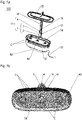
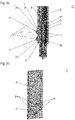
- The lightguide portion 2' of the optical element 1' shown in
Figure 3a comprises two bulbous lenses 2'a each having a respective recess R at their side facing the printed circuit board 12'. In the situation depicted inFigure 3 , the lightguide portion 2' has been placed on the light sources 13'. Therein, each of the bulbous lenses 2'a runs through a respective one of openings O, and is thus framed by a portion of the housing component 4'. Thereby, in particular, the printed circuit board 12' is masked. - Moreover, the lightguide portion 2' is placed such that each recess R at least partially accommodates a respective one of the light sources 13'. Thereby, the light emitted - in operation - by the light sources 13' is fully or at least almost fully fed into the lightguide portion 2' and focussed thereby to an exterior environment of the housing component 4'. In particular, a light loss in the interior of the housing component 4' and/or an undesired illumination of a backside of the mount system are prevented. By contrast, the bulbous lenses 2'a with their respective (preferably paraboloidal) focus F provide for a projection of light L in front of the mount system component 11' and, therewith, an advantageous light distribution among plants eventually growing in a plant tray as that shown in
Figures 1a, 1b . - Disclosed is an
optical element 1, 1' for ahydroponic system 100 comprising atop lamp 20 and amount system 10 holding thetop lamp 20. The optical element comprises at least onelightguide portion 2, 2' configured to be placed, through one or more openings/s O of ahousing component 4, 4' of themount system 10, on or over one or more light source/s 13, 13' facing the one or more openings O and being mounted on a printedcircuit board 12, 12' arranged within thehousing component 4, 4'. In such position, thelightguide portion 2, 2' is further configured to focus light of the one or more light source/s 13, 13' to an exterior environment of thehousing component 4, 4'. - Further disclosed are a
mount system component 11, 11' comprising suchoptical element 1, 1', and ahydroponic system 100 comprising one or more such mount system component/s 11, 11'. -
- 1, 1'
- optical element
- 2, 2'
- lightguide portion
- 2a
- batwing lens
- 2'a
- bulbous lens
- 3, 3'
- clip portion
- 4, 4'
- housing component
- 10
- mount system
- 11, 11'
- mount system component
- 12, 12'
- printed circuit board
- 13, 13'
- light source
- 20
- top lamp
- 30
- watering tank
- 40
- plant tray
- 50
- capsule holder
- 60
- base station
- 61
- electric connection
- 100
- hydroponic system
- C
- opening for plant capsule
- F
- focus
- L
- light
- O
- opening in
housing component 4, 4' - R
- recess in bulbous lens 2'a
Claims (8)
- Optical element (1, 1') for a hydroponic system (100) comprising a top lamp (20) and a mount system (10) holding the top lamp (20), the optical element comprising at least one lightguide portion (2, 2') configured- to be placed, through one or more openings/s (O) in a housing component (4, 4') of the mount system (10), on or over one or more light source/s (13, 13') mounted on a printed circuit board (12, 12') arranged within the housing component (4, 4'), the one or more light source/s (13, 13') facing the one or more openings (O); and- in such position, to focus light of the one or more light source/s (13) to an exterior environment of the housing component (4, 4').
- Optical element according to claim 1, wherein the at least one lightguide portion (2) comprises at least one batwing lens (2a).
- Optical element according to one of claims 1 or 2, wherein the at least one lightguide portion (2') comprises at least one bulbous lens (2'a).
- Optical element according to claim 3, wherein the at least one bulbous lens (2'a) has a recess (R) configured to receive a respective one of the one or more light source/s (13) when the lightguide portion (2') is placed thereon or thereover.
- Optical element according to one of the preceding claims, wherein the optical element further comprises a clip portion (3, 3') configured to detachably fix the at least one lightguide portion (2, 2') to the housing component (4, 4'), wherein- the clip portion (3) is separate or separable from the at least one lightguide portion (2) or- at least a part of the clip portion (3') is permanently connected to the lightguide portion (2').
- Optical element according to claim 5, wherein the clip portion (3, 3') comprises one or more snap fit/s and/or one or more magnets for fixation of the lightguide portion (2, 2') to the housing component (10).
- Mount system component (11, 11') of a mount system (10) holding a top lamp (20) of a hydroponic system (100), the mount system component (11, 11') comprising a housing component (4, 4') with one or more opening (O), a printed circuit board (12, 12') arranged within the housing component and having mounted thereon one or more light sources (13, 13') facing the one or more opening/s, and a matching optical element (1, 1') according to one of the preceding claims.
- Hydroponic system (100) comprising- a watering tank (30),- a plant tray (40),- a top lamp (20) configured to illuminate the plant tray (40), and- a mount system (10) holding the top lamp (20), wherein the mount system (10) comprises one or more mount system component/s (11, 11') according to claim 7.
Priority Applications (2)
| Application Number | Priority Date | Filing Date | Title |
|---|---|---|---|
| EP21175298.5A EP4091438A1 (en) | 2021-05-21 | 2021-05-21 | Optical element and mount system for a hydroponic system, and hydroponic system therewith |
| CN202210548392.XA CN115362843A (en) | 2021-05-21 | 2022-05-20 | Optical element and mounting system for hydroponic system and hydroponic system |
Applications Claiming Priority (1)
| Application Number | Priority Date | Filing Date | Title |
|---|---|---|---|
| EP21175298.5A EP4091438A1 (en) | 2021-05-21 | 2021-05-21 | Optical element and mount system for a hydroponic system, and hydroponic system therewith |
Publications (1)
| Publication Number | Publication Date |
|---|---|
| EP4091438A1 true EP4091438A1 (en) | 2022-11-23 |
Family
ID=76059755
Family Applications (1)
| Application Number | Title | Priority Date | Filing Date |
|---|---|---|---|
| EP21175298.5A Pending EP4091438A1 (en) | 2021-05-21 | 2021-05-21 | Optical element and mount system for a hydroponic system, and hydroponic system therewith |
Country Status (2)
| Country | Link |
|---|---|
| EP (1) | EP4091438A1 (en) |
| CN (1) | CN115362843A (en) |
Citations (4)
| Publication number | Priority date | Publication date | Assignee | Title |
|---|---|---|---|---|
| US20140041291A1 (en) * | 2012-08-13 | 2014-02-13 | Fiskars Brands Finland Oy Ab | Growth container |
| US20180135830A1 (en) * | 2016-11-15 | 2018-05-17 | Eye Lighting International Of North America, Inc. | Led grow light |
| CN208011430U (en) * | 2018-02-09 | 2018-10-26 | 漳州立达信光电子科技有限公司 | Down lamp |
| WO2021041087A1 (en) * | 2019-08-30 | 2021-03-04 | Fluence Bioengineering, Inc. | Method of illuminating a horticultural intracanopy space |
-
2021
- 2021-05-21 EP EP21175298.5A patent/EP4091438A1/en active Pending
-
2022
- 2022-05-20 CN CN202210548392.XA patent/CN115362843A/en active Pending
Patent Citations (4)
| Publication number | Priority date | Publication date | Assignee | Title |
|---|---|---|---|---|
| US20140041291A1 (en) * | 2012-08-13 | 2014-02-13 | Fiskars Brands Finland Oy Ab | Growth container |
| US20180135830A1 (en) * | 2016-11-15 | 2018-05-17 | Eye Lighting International Of North America, Inc. | Led grow light |
| CN208011430U (en) * | 2018-02-09 | 2018-10-26 | 漳州立达信光电子科技有限公司 | Down lamp |
| WO2021041087A1 (en) * | 2019-08-30 | 2021-03-04 | Fluence Bioengineering, Inc. | Method of illuminating a horticultural intracanopy space |
Also Published As
| Publication number | Publication date |
|---|---|
| CN115362843A (en) | 2022-11-22 |
Similar Documents
| Publication | Publication Date | Title |
|---|---|---|
| US7473008B2 (en) | Marine LED lighting system and method | |
| US20160262313A1 (en) | Lighting System for Promoting the Rapid Maturation of Commercial Plants | |
| US5067059A (en) | Aquarium ornament lamp source | |
| US11154039B2 (en) | LED terrarium light for reptiles, amphibians, and birds, using an extended point source LED array with light emitting diodes of multiple wavelengths | |
| AU2020326737B2 (en) | Plant enclosure with vertically distributed light sources | |
| US20160273755A1 (en) | Plant-growing lamp capable of effecting change in local environment | |
| CA1292360C (en) | Apparatus for stimulating plant growth under controlled conditions | |
| KR101334603B1 (en) | Plant cultivation apparatus having darkroom maintain cover | |
| CA3081149A1 (en) | Horticulture grow system for horticulture | |
| CN204104459U (en) | Plant growing device and lighting device | |
| EP4091438A1 (en) | Optical element and mount system for a hydroponic system, and hydroponic system therewith | |
| KR101868743B1 (en) | Apparatus for plant cultivation using plant information | |
| CN205511374U (en) | Soilless culture device | |
| JP7000832B2 (en) | Climbing lumber of vines and greening equipment equipped with them | |
| CN205511376U (en) | Soilless cultivation device | |
| US12082540B2 (en) | Plant cultivation apparatus and method | |
| CN105875390A (en) | Eye-protecting desk lamp with plant and plant cultivation method adopting eye-protecting desk lamp | |
| JP2014180267A (en) | Led light guide plate illumination unit and cultivation device including the illumination unit | |
| KR20220047902A (en) | LED Plantation Unit | |
| CN205623660U (en) | Soilless culture device | |
| CN219352456U (en) | Plant growth desk lamp | |
| KR102238449B1 (en) | Glass block for frowing plants | |
| CN216392270U (en) | Solar landscape flowerpot | |
| TW202043674A (en) | Plant spike light and spike light assembly including a plurality of the plant spike lights | |
| KR20140101618A (en) | Led with a mini flower pots |
Legal Events
| Date | Code | Title | Description |
|---|---|---|---|
| PUAI | Public reference made under article 153(3) epc to a published international application that has entered the european phase |
Free format text: ORIGINAL CODE: 0009012 |
|
| STAA | Information on the status of an ep patent application or granted ep patent |
Free format text: STATUS: THE APPLICATION HAS BEEN PUBLISHED |
|
| AK | Designated contracting states |
Kind code of ref document: A1 Designated state(s): AL AT BE BG CH CY CZ DE DK EE ES FI FR GB GR HR HU IE IS IT LI LT LU LV MC MK MT NL NO PL PT RO RS SE SI SK SM TR |
|
| STAA | Information on the status of an ep patent application or granted ep patent |
Free format text: STATUS: REQUEST FOR EXAMINATION WAS MADE |
|
| 17P | Request for examination filed |
Effective date: 20230523 |
|
| RBV | Designated contracting states (corrected) |
Designated state(s): AL AT BE BG CH CY CZ DE DK EE ES FI FR GB GR HR HU IE IS IT LI LT LU LV MC MK MT NL NO PL PT RO RS SE SI SK SM TR |