EP4091256B1 - Dai- und codebuch-aktualisierung für dci-planung von mehreren ccs - Google Patents
Dai- und codebuch-aktualisierung für dci-planung von mehreren ccs Download PDFInfo
- Publication number
- EP4091256B1 EP4091256B1 EP20913282.8A EP20913282A EP4091256B1 EP 4091256 B1 EP4091256 B1 EP 4091256B1 EP 20913282 A EP20913282 A EP 20913282A EP 4091256 B1 EP4091256 B1 EP 4091256B1
- Authority
- EP
- European Patent Office
- Prior art keywords
- dai
- component carriers
- dci
- counter
- value
- Prior art date
- Legal status (The legal status is an assumption and is not a legal conclusion. Google has not performed a legal analysis and makes no representation as to the accuracy of the status listed.)
- Active
Links
Images





Classifications
-
- H—ELECTRICITY
- H04—ELECTRIC COMMUNICATION TECHNIQUE
- H04L—TRANSMISSION OF DIGITAL INFORMATION, e.g. TELEGRAPHIC COMMUNICATION
- H04L1/00—Arrangements for detecting or preventing errors in the information received
- H04L1/12—Arrangements for detecting or preventing errors in the information received by using return channel
- H04L1/16—Arrangements for detecting or preventing errors in the information received by using return channel in which the return channel carries supervisory signals, e.g. repetition request signals
- H04L1/18—Automatic repetition systems, e.g. Van Duuren systems
- H04L1/1822—Automatic repetition systems, e.g. Van Duuren systems involving configuration of automatic repeat request [ARQ] with parallel processes
-
- H—ELECTRICITY
- H04—ELECTRIC COMMUNICATION TECHNIQUE
- H04L—TRANSMISSION OF DIGITAL INFORMATION, e.g. TELEGRAPHIC COMMUNICATION
- H04L1/00—Arrangements for detecting or preventing errors in the information received
- H04L1/12—Arrangements for detecting or preventing errors in the information received by using return channel
- H04L1/16—Arrangements for detecting or preventing errors in the information received by using return channel in which the return channel carries supervisory signals, e.g. repetition request signals
- H04L1/18—Automatic repetition systems, e.g. Van Duuren systems
- H04L1/1829—Arrangements specially adapted for the receiver end
- H04L1/1854—Scheduling and prioritising arrangements
-
- H—ELECTRICITY
- H04—ELECTRIC COMMUNICATION TECHNIQUE
- H04L—TRANSMISSION OF DIGITAL INFORMATION, e.g. TELEGRAPHIC COMMUNICATION
- H04L1/00—Arrangements for detecting or preventing errors in the information received
- H04L1/12—Arrangements for detecting or preventing errors in the information received by using return channel
- H04L1/16—Arrangements for detecting or preventing errors in the information received by using return channel in which the return channel carries supervisory signals, e.g. repetition request signals
- H04L1/18—Automatic repetition systems, e.g. Van Duuren systems
- H04L1/1867—Arrangements specially adapted for the transmitter end
- H04L1/1887—Scheduling and prioritising arrangements
-
- H—ELECTRICITY
- H04—ELECTRIC COMMUNICATION TECHNIQUE
- H04L—TRANSMISSION OF DIGITAL INFORMATION, e.g. TELEGRAPHIC COMMUNICATION
- H04L1/00—Arrangements for detecting or preventing errors in the information received
- H04L1/12—Arrangements for detecting or preventing errors in the information received by using return channel
- H04L1/16—Arrangements for detecting or preventing errors in the information received by using return channel in which the return channel carries supervisory signals, e.g. repetition request signals
- H04L1/18—Automatic repetition systems, e.g. Van Duuren systems
- H04L1/1867—Arrangements specially adapted for the transmitter end
- H04L1/1896—ARQ related signaling
-
- H—ELECTRICITY
- H04—ELECTRIC COMMUNICATION TECHNIQUE
- H04L—TRANSMISSION OF DIGITAL INFORMATION, e.g. TELEGRAPHIC COMMUNICATION
- H04L5/00—Arrangements affording multiple use of the transmission path
- H04L5/0001—Arrangements for dividing the transmission path
- H04L5/0003—Two-dimensional division
- H04L5/0005—Time-frequency
- H04L5/0007—Time-frequency the frequencies being orthogonal, e.g. OFDM(A) or DMT
- H04L5/001—Time-frequency the frequencies being orthogonal, e.g. OFDM(A) or DMT the frequencies being arranged in component carriers
-
- H—ELECTRICITY
- H04—ELECTRIC COMMUNICATION TECHNIQUE
- H04L—TRANSMISSION OF DIGITAL INFORMATION, e.g. TELEGRAPHIC COMMUNICATION
- H04L5/00—Arrangements affording multiple use of the transmission path
- H04L5/003—Arrangements for allocating sub-channels of the transmission path
- H04L5/0048—Allocation of pilot signals, i.e. of signals known to the receiver
-
- H—ELECTRICITY
- H04—ELECTRIC COMMUNICATION TECHNIQUE
- H04L—TRANSMISSION OF DIGITAL INFORMATION, e.g. TELEGRAPHIC COMMUNICATION
- H04L5/00—Arrangements affording multiple use of the transmission path
- H04L5/003—Arrangements for allocating sub-channels of the transmission path
- H04L5/0053—Allocation of signalling, i.e. of overhead other than pilot signals
- H04L5/0055—Physical resource allocation for ACK/NACK
-
- H—ELECTRICITY
- H04—ELECTRIC COMMUNICATION TECHNIQUE
- H04L—TRANSMISSION OF DIGITAL INFORMATION, e.g. TELEGRAPHIC COMMUNICATION
- H04L5/00—Arrangements affording multiple use of the transmission path
- H04L5/0091—Signalling for the administration of the divided path, e.g. signalling of configuration information
- H04L5/0092—Indication of how the channel is divided
-
- H—ELECTRICITY
- H04—ELECTRIC COMMUNICATION TECHNIQUE
- H04L—TRANSMISSION OF DIGITAL INFORMATION, e.g. TELEGRAPHIC COMMUNICATION
- H04L5/00—Arrangements affording multiple use of the transmission path
- H04L5/0001—Arrangements for dividing the transmission path
- H04L5/0014—Three-dimensional division
- H04L5/0023—Time-frequency-space
Definitions
- the present disclosure relates generally to communication systems, and more particularly, to updating a downlink assignment index (DAI) and a corresponding codebook in the case of a downlink control information (DCI) scheduling multiple component carriers (CCs).
- DCI downlink assignment index
- CCs multiple component carriers
- Wireless communication systems are widely deployed to provide various telecommunication services such as telephony, video, data, messaging, and broadcasts.
- Typical wireless communication systems may employ multiple-access technologies capable of supporting communication with multiple users by sharing available system resources. Examples of such multiple-access technologies include code division multiple access (CDMA) systems, time division multiple access (TDMA) systems, frequency division multiple access (FDMA) systems, orthogonal frequency division multiple access (OFDMA) systems, single-carrier frequency division multiple access (SC-FDMA) systems, and time division synchronous code division multiple access (TD-SCDMA) systems.
- CDMA code division multiple access
- TDMA time division multiple access
- FDMA frequency division multiple access
- OFDMA orthogonal frequency division multiple access
- SC-FDMA single-carrier frequency division multiple access
- TD-SCDMA time division synchronous code division multiple access
- 5G New Radio is part of a continuous mobile broadband evolution promulgated by Third Generation Partnership Project (3GPP) to meet new requirements associated with latency, reliability, security, scalability (e.g., with Internet of Things (IoT)), and other requirements.
- 3GPP Third Generation Partnership Project
- 5G NR includes services associated with enhanced mobile broadband (eMBB), massive machine type communications (mMTC), and ultra reliable low latency communications (URLLC).
- eMBB enhanced mobile broadband
- mMTC massive machine type communications
- URLLC ultra reliable low latency communications
- Some aspects of 5G NR may be based on the 4G Long Term Evolution (LTE) standard.
- LTE Long Term Evolution
- CHINA TELECOM "Discussion on Multi-TRPIPanel Transmission enhancements", 3GPP DRAFT; R1-1911235, 3RD GENERATION PARTNERSHIP PROJECT (3GPP), MOBILE COMPETENCE CENTRE; 650, ROUTE DES LUCIOLES; F-06921 SOPHIA-ANTIPOLIS CEDEX; FRANCE, vol. RAN WG1, no. Chongqing, China; 20191014 - 20191020, 4 October 2019 (2019-10-04 ) discusses enhancements for multi-TRP/panel transmission, and related proposals.
- ERICSSON "New WID on NR Dynamic spectrum sharing (DSS)", 3GPP DRAFT; RP-193260, 3RD GENERATION PARTNERSHIP PROJECT (3GPP), MOBILE COMPETENCE CENTRE; 650, ROUTE DES LUCIOLES; F-06921 SOPHIA-ANTIPOLIS CEDEX; FRANCE, vol. TSGRAN, no. Sitges, Spain; 20191209 - 20191212, 12 December 2019 (2019-12-12 ) discusses a new WID for NR DSS.
- DSS Dynamic spectrum sharing
- the present disclosure relates to updating a downlink assignment index (DAI) and a corresponding codebook in the case of a downlink control information (DCI) scheduling multiple component carriers (CCs), which may also be referred to herein as cells.
- DCI downlink control information
- CCs component carriers
- the techniques described herein enable a base station and UE to accurately identify control signaling messages and/or data messages and their receipt status, particularly in the case of cross-carrier scheduling.
- the present solutions may improve efficiency in cross-carrier scheduling scenarios, e.g., carrier aggregation, as well as in dynamic spectrum sharing scenarios.
- the disclosed methods, apparatus, and computer-readable media are directed to updating a downlink assignment index (DAI) communicated to a UE for reporting feedback on downlink signaling in a case where a single downlink control information (DCI) transmitted on the control channels of multiple component carriers schedules transmissions on each of the multiple component carriers.
- the DAI may be used to track a number of scheduled transmissions to be acknowledged based on a hybrid automatic repeat request (HARQ) codebook.
- HARQ hybrid automatic repeat request
- the DCI may be updated based on the number of component carriers.
- the base station transmitting the DCI may update the DAI based on one or any combination of an index of a scheduled component carrier, a DAI counter value, and/or a monitoring occasion.
- the feedback information from the UE e.g., the HARQ codebook for a physical uplink control channel (PUCCH) transmission may also be updated and/or formatted based on the number of component carriers on which the DCI is received. More specifically, for instance, when transmitting bundled feedback information, the UE may updated the HARQ codebook such that each component carrier per detected DCI is counted as one position for a HARQ acknowledgement bit of the scheduled PDSCH in the PUCCH transmission.
- the UE may format the HARQ acknowledgement positions to be first sorted/ordered based on ascending order of scheduled component carrier index in the same PDCCH monitoring occasion, then based on ascending order of PDCCH monitoring occasion index.
- processors include microprocessors, microcontrollers, graphics processing units (GPUs), central processing units (CPUs), application processors, digital signal processors (DSPs), reduced instruction set computing (RISC) processors, systems on a chip (SoC), baseband processors, field programmable gate arrays (FPGAs), programmable logic devices (PLDs), state machines, gated logic, discrete hardware circuits, and other suitable hardware configured to perform the various functionality described throughout this disclosure.
- processors in the processing system may execute software.
- Software shall be construed broadly to mean instructions, instruction sets, code, code segments, program code, programs, subprograms, software components, applications, software applications, software packages, routines, subroutines, objects, executables, threads of execution, procedures, functions, etc., whether referred to as software, firmware, middleware, microcode, hardware description language, or otherwise.
- the functions described may be implemented in hardware, software, or any combination thereof. If implemented in software, the functions may be stored on or encoded as one or more instructions of code on a computer-readable medium.
- Computer-readable media includes computer storage media. Storage media may be any available media that can be accessed by a computer.
- such computer-readable media can comprise a random-access memory (RAM), a read-only memory (ROM), an electrically erasable programmable ROM (EEPROM), optical disk storage, magnetic disk storage, other magnetic storage devices, combinations of the aforementioned types of computer-readable media, or any other medium that can be used to store computer executable code in the form of instructions or data structures that can be accessed by a computer.
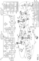
- an example of a wireless communications system (also referred to as a wireless wide area network (WWAN)) defines an access network 100 including base stations 102, UEs 104, an Evolved Packet Core (EPC) 160, and another core network 190 (e.g., a 5G Core (5GC)).
- WWAN wireless wide area network
- EPC Evolved Packet Core
- 5GC 5G Core
- the base station 102 and the UE 104 may have established communications on multiple component carriers (CC), and the base station 102 may schedule the UE 104 on multiple CCs using a single DC.
- the base station 102 includes a communication component 141 in communication with the UE 104 and having a downlink assignment index (DAI) indication component 143 configured to generate DAI information 145 for transmission with a single downlink control information (DCI) 147 that schedules resources for monitoring by the UE 104 on a plurality of CCs.
- the plurality of CCs may be up to n CCs, where n is a positive integer, and where such DCI is indicated by the notation DCI CC1-CCn .
- the DCI 147 may perform cross-carrier scheduling by indicating resources to the UE 104 for a first downlink (DL) signal on a first CC, e.g., DL signal CC1 149, and up to an nth DL signal on an nth CC, e.g., up to DL signal CCn 151.
- the DAI information 145 may be used to identify specific feedback, e.g., feedback 146 up to feedback 148, with respect to each of the scheduled DL signals on each of the multiple CCs within a set of bundled feedback information 144, such as a HARQ codebook.
- the feedback may include, for example, an acknowledgement (ACK) or a negative acknowledgement (NACK) of each respective DL signal.
- the UE 104 may include a communication component 140 in communication with the base station 104 and having an ACK/NACK feedback indication component 142 configured to generate the bundled feedback information 144 based on the DAI information 145 from the DCI 147 and in response to receipt of the plurality of DL signals, e.g., DL signal CC1 149 up to DL signal CCn 151, on the multiple CCs.
- a communication component 140 in communication with the base station 104 and having an ACK/NACK feedback indication component 142 configured to generate the bundled feedback information 144 based on the DAI information 145 from the DCI 147 and in response to receipt of the plurality of DL signals, e.g., DL signal CC1 149 up to DL signal CCn 151, on the multiple CCs.
- implementation of the present solution a base station and UE to accurately identify control signaling messages and/or data messages and their receipt status, particularly in the case of cross-carrier scheduling.
- the present solutions may improve efficiency in cross-carrier scheduling scenarios, e g., carrier aggregation, as well as in dynamic spectrum sharing scenarios. Further details of the present solution are described in detail in the subsequent figures.
- the base stations 102 may include macrocells (e.g., a relatively higher power cellular base station) and/or small cells (e.g., relatively lower power cellular base station).
- the macrocells include base stations.
- the small cells include femtocells, picocells, and microcells.
- Some of the base stations 102 may be configured for 4G LTE (collectively referred to as Evolved Universal Mobile Telecommunications System (UMTS) Terrestrial Radio Access Network (E-UTRAN)) may interface with the EPC 160 through first backhaul links 132 (e.g., S1 interface).
- UMTS Evolved Universal Mobile Telecommunications System
- E-UTRAN Evolved Universal Mobile Telecommunications System
- first backhaul links 132 e.g., S1 interface
- the base stations 102 may be configured for 5G NR (collectively referred to as Next Generation RAN (NG-RAN)) may interface with core network 190 through second backhaul links 184.
- the base stations 102 may perform one or more of the following functions: transfer of user data, radio channel ciphering and deciphering, integrity protection, header compression, mobility control functions (e.g., handover, dual connectivity), inter-cell interference coordination, connection setup and release, load balancing, distribution for non-access stratum (NAS) messages, NAS node selection, synchronization, radio access network (RAN) sharing, multimedia broadcast multicast service (MBMS), subscriber and equipment trace, RAN information management (RIM), paging, positioning, and delivery of warning messages.
- NAS non-access stratum
- RAN radio access network
- MBMS multimedia broadcast multicast service
- RIM RAN information management
- the base stations 102 may communicate directly or indirectly (e.g., through the EPC 160 or core network 190) with each other over third backhaul links 134 (e.g., X2 interface).
- the third backhaul links 134 may be wired or wireless.
- the base stations 102 may wirelessly communicate with the UEs 104. Each of the base stations 102 may provide communication coverage for a respective geographic coverage area 110. There may be overlapping geographic coverage areas 110. For example, the small cell 102' may have a coverage area 110' that overlaps the coverage area 110 of one or more macro base stations 102.
- a network that includes both small cell and macrocells may be known as a heterogeneous network.
- a heterogeneous network may also include Home Evolved Node Bs (eNBs) (HeNBs), which may provide service to a restricted group known as a closed subscriber group (CSG).
- eNBs Home Evolved Node Bs
- CSG closed subscriber group
- the communication links 120 between the base stations 102 and the UEs 104 may include uplink (UL) (also referred to as reverse link) transmissions from a UE 104 to a base station 102 and/or downlink (DL) (also referred to as forward link) transmissions from a base station 102 to a UE 104.
- the communication links 120 may use multiple-input and multiple-output (MIMO) antenna technology, including spatial multiplexing, beamforming, and/or transmit diversity.
- the communication links may be through one or more carriers.
- the base stations 102 / UEs 104 may use spectrum up to Y MHz (e.g., 5, 10, 15, 20, 100, 400, etc.
- the component carriers may include a primary component carrier and one or more secondary component carriers.
- a primary component carrier may be referred to as a primary cell (PCell) and a secondary component carrier may be referred to as a secondary cell (SCell).
- D2D communication link 158 may use the DL/UL WWAN spectrum.
- the D2D communication link 158 may use one or more sidelink channels, such as a physical sidelink broadcast channel (PSBCH), a physical sidelink discovery channel (PSDCH), a physical sidelink shared channel (PSSCH), and a physical sidelink control channel (PSCCH).
- sidelink channels such as a physical sidelink broadcast channel (PSBCH), a physical sidelink discovery channel (PSDCH), a physical sidelink shared channel (PSSCH), and a physical sidelink control channel (PSCCH).
- sidelink channels such as a physical sidelink broadcast channel (PSBCH), a physical sidelink discovery channel (PSDCH), a physical sidelink shared channel (PSSCH), and a physical sidelink control channel (PSCCH).
- sidelink channels such as a physical sidelink broadcast channel (PSBCH), a physical sidelink discovery channel (PSDCH), a physical sidelink shared channel (PSSCH), and a physical sidelink control channel (PSCCH).
- the wireless communications system may further include a Wi-Fi access point (AP) 150 in communication with Wi-Fi stations (STAs) 152 via communication links 154 in a 5 GHz unlicensed frequency spectrum.
- AP Wi-Fi access point
- STAs Wi-Fi stations
- communication links 154 in a 5 GHz unlicensed frequency spectrum.
- the STAs 152 / AP 150 may perform a clear channel assessment (CCA) prior to communicating in order to determine whether the channel is available.
- CCA clear channel assessment
- the small cell 102' may operate in a licensed and/or an unlicensed frequency spectrum When operating in an unlicensed frequency spectrum, the small cell 102' may employ NR and use the same 5 GHz unlicensed frequency spectrum as used by the Wi-Fi AP 150. The small cell 102', employing NR in an unlicensed frequency spectrum, may boost coverage to and/or increase capacity of the access network.
- a base station 102 may include and/or be referred to as an eNB, gNodeB (gNB), or another type of base station.
- Some base stations, such as gNB 180 may operate in a traditional sub 6 GHz spectrum, in millimeter wave (mmW) frequencies, and/or near mmW frequencies in communication with the UE 104.
- mmW millimeter wave
- mmW base station Extremely high frequency (EHF) is part of the RF in the electromagnetic spectrum.
- EHF Extremely high frequency
- EHF has a range of 30 GHz to 300 GHz and a wavelength between 1 millimeter and 10 millimeters. Radio waves in the band may be referred to as a millimeter wave. Near mmW may extend down to a frequency of 3 GHz with a wavelength of 100 millimeters.
- the super high frequency (SHF) band extends between 3 GHz and 30 GHz, also referred to as centimeter wave. Communications using the mmW / near mmW radio frequency band (e.g., 3 GHz - 300 GHz) has extremely high path loss and a short range.
- the mmW base station 180 may utilize beamforming 182 with the UE 104 to compensate for the extremely high path loss and short range.
- the base station 180 and the UE 104 may each include a plurality of antennas, such as antenna elements, antenna panels, and/or antenna arrays to facilitate the beamforming.
- the base station 180 may transmit a beamformed signal to the UE 104 in one or more transmit directions 182'.
- the UE 104 may receive the beamformed signal from the base station 180 in one or more receive directions 182".
- the UE 104 may also transmit a beamformed signal to the base station 180 in one or more transmit directions.
- the base station 180 may receive the beamformed signal from the UE 104 in one or more receive directions.
- the base station 180 / UE 104 may perform beam training to determine the best receive and transmit directions for each of the base station 180 / UE 104.
- the transmit and receive directions for the base station 180 may or may not be the same.
- the transmit and receive directions for the UE 104 may or may not be the same.
- the EPC 160 may include a Mobility Management Entity (MME) 162, other MMEs 164, a Serving Gateway 166, a Multimedia Broadcast Multicast Service (MBMS) Gateway 168, a Broadcast Multicast Service Center (BM-SC) 170, and a Packet Data Network (PDN) Gateway 172.
- MME Mobility Management Entity
- MBMS Multimedia Broadcast Multicast Service
- BM-SC Broadcast Multicast Service Center
- PDN Packet Data Network
- the MME 162 may be in communication with a Home Subscriber Server (HSS) 1 74.
- HSS Home Subscriber Server
- the MME 162 is the control node that processes the signaling between the UEs 104 and the EPC 160.
- the MME 162 provides bearer and connection management. All user Internet protocol (IP) packets are transferred through the Serving Gateway 166, which itself is connected to the PDN Gateway 172.
- IP Internet protocol
- the PDN Gateway 172 provides UE IP address allocation as well as other functions.
- the PDN Gateway 172 and the BM-SC 170 are connected to the IF Services 176.
- the IP Services 176 may include the Internet, an intranet, an IP Multimedia Subsystem (IMS), a PS Streaming Service, and/or other IP services.
- the BM-SC 170 may provide functions for MBMS user service provisioning and delivery.
- the BM-SC 170 may serve as an entry point for content provider MBMS transmission, may be used to authorize and initiate MBMS Bearer Services within a public land mobile network (PLMN), and may be used to schedule MBMS transmissions.
- PLMN public land mobile network
- the MBMS Gateway 168 may be used to distribute MBMS traffic to the base stations 102 belonging to a Multicast Broadcast Single Frequency Network (MBSFN) area broadcasting a particular service, and may be responsible for session management (start/stop) and for collecting eMBMS related charging information.
- MMSFN Multicast Broadcast Single Frequency Network
- the core network 190 may include a Access and Mobility Management Function (AMF) 192, other AMFs 193, a Session Management Function (SMF) 194, and a User Plane Function (UPF) 195.
- the AMF 192 may be in communication with a Unified Data Management (UDM) 196.
- the AMF 192 is the control node that processes the signaling between the UEs 104 and the core network 190.
- the AMF 192 provides QoS flow and session management. All user Internet protocol (IP) packets are transferred through the UPF 195.
- the UPF 195 provides UE IP address allocation as well as other functions.
- the UPF 195 is connected to the IP Services 197.
- the IP Services 197 may include the Internet, an intranet, an IP Multimedia Subsystems (IMS), a PS Streaming Service, and/or other IP services.
- IMS IP Multimedia Subsystems
- the base station may include and/or be referred to as a gNB, Node B, eNB, an access point, a base transceiver station, a radio base station, a radio transceiver, a transceiver function, a basic service set (BSS), an extended service set (ESS), a transmit reception point (TRP), or some other suitable terminology.
- the base station 102 provides an access point to the EPC 160 or core network 190 for a UE 104.
- Examples of UEs 104 include a cellular phone, a smart phone, a session initiation protocol (SIP) phone, a laptop, a personal digital assistant (PDA), a satellite radio, a global positioning system, a multimedia device, a video device, a digital audio player (e.g., MP3 player), a camera, a game console, a tablet, a smart device, a wearable device, a vehicle, an electric meter, a gas pump, a large or small kitchen appliance, a healthcare device, an implant, a sensor/actuator, a display, or any other similar functioning device.
- SIP session initiation protocol
- PDA personal digital assistant
- the UEs 104 may be referred to as IoT devices (e.g., parking meter, gas pump, toaster, vehicles, heart monitor, etc.).
- the UE 104 may also be referred to as a station, a mobile station, a subscriber station, a mobile unit, a subscriber unit, a wireless unit, a remote unit, a mobile device, a wireless device, a wireless communications device, a remote device, a mobile subscriber station, an access terminal, a mobile terminal, a wireless terminal, a remote terminal, a handset, a user agent, a mobile client, a client, or some other suitable terminology.
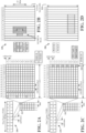
- the base station 102 and UE 104 described herein may utilize one or more examples 200, 230, 250, and/or 280 of frame structures, resources, and communication channels for exchanging communications as described herein.
- the 5G/NR frame structure may be FDD in which for a particular set of subcarriers (carrier system bandwidth), subframes within the set of subcarriers are dedicated for either DL or UL, or may be TDD in which for a particular set of subcarriers (carrier system bandwidth), subframes within the set of subcarriers are dedicated for both DL and UL.
- the 5G/NR frame structure is assumed to be TDD, with subframe 4 being configured with slot format 28 (with mostly DL), where D is DL, U is UL, and X is flexible for use between DL/UL, and subframe 3 being configured with slot format 34 (with mostly UL). While subframes 3, 4 are shown with slot formats 34, 28, respectively, any particular subframe may be configured with any of the various available slot formats 0-61. Slot formats 0, 1 are all DL, UL, respectively. Other slot formats 2-61 include a mix of DL, UL, and flexible symbols.
- UEs are configured with the slot format (dynamically through DL control information (DCI), or semi-statically/statically through radio resource control (RRC) signaling) through a received slot format indicator (SFI).
- DCI DL control information
- RRC radio resource control
- SFI received slot format indicator
- a frame (10 ms) may be divided into 10 equally sized subframes (1 ms). Each subframe may include one or more time slots. Subframes may also include mini-slots, which may include 7, 4, or 2 symbols. Each slot may include 7 or 14 symbols, depending on the slot configuration. For slot configuration 0, each slot may include 14 symbols, and for slot configuration 1, each slot may include 7 symbols.
- the symbols on DL may be cyclic prefix (CP) OFDM (CP-OFDM) symbols.
- the symbols on UL may be CP-OFDM symbols (for high throughput scenarios) or discrete Fourier transform (DFT) spread OFDM (DFT-s-OFDM) symbols (also referred to as single carrier frequency-division multiple access (SC-FDMA) symbols) (for power limited scenarios; limited to a single stream transmission).
- the number of slots within a subframe is based on the slot configuration and the numerology. For slot configuration 0, different numerologies ⁇ 0 to 5 allow for 1, 2, 4, 8, 16, and 32 slots, respectively, per subframe. For slot configuration 1, different numerologies 0 to 2 allow for 2, 4, and 8 slots, respectively, per subframe. Accordingly, for slot configuration 0 and numerology ⁇ , there are 14 symbols/slot and 2 ⁇ slots/subframe.
- the subcarrier spacing and symbol length/duration are a function of the numerology.
- the subcarrier spacing may be equal to 2 ⁇ * 15 kHz, where ⁇ is the numerology 0 to 5.
- the symbol length/duration is inversely related to the subcarrier spacing.
- the slot duration is 0.25 ms
- the subcarrier spacing is 60 kHz
- the symbol duration is approximately 16.67 ⁇ s
- a resource grid may be used to represent the frame structure.
- Each time slot includes a resource block (R13) (also referred to as physical R13s (PRBs)) that extends 12 consecutive subcarriers.
- R13 resource block
- PRBs physical R13s
- the resource grid is divided into multiple resource elements (REs). The number of bits carried by each RE depends on the modulation scheme.
- diagram 230 includes an example of various DL channels within a subframe of a frame.
- the physical downlink control channel (PDCCH) carries DCI within one or more control channel elements (CCEs), each CCE including nine RE groups (REGs), each REG including four consecutive REs in an OFDM symbol.
- a primary synchronization signal (PSS) may be within symbol 2 of particular subframes of a frame. The PSS is used by a UE 104 to determine subframe/symbol timing and a physical layer identity.
- a secondary synchronization signal (SSS) may be within symbol 4 of particular subframes of a frame. The SSS is used by a UE to determine a physical layer cell identity group number and radio frame timing.
- the UE can determine a physical cell identifier (PCI). Based on the PCI, the UE can determine the locations of the aforementioned DM-RS.
- the physical broadcast channel (PBCH) which carries a master information block (MIB), may be logically grouped with the PSS and SSS to form a synchronization signal (SS)/PBCH block.
- the MIB provides a number of RBs in the system bandwidth and a system frame number (SFN).
- the physical downlink shared channel (PDSCH) carries user data, broadcast system information not transmitted through the PBCH such as system information blocks (SIBs), and paging messages.
- SIBs system information blocks
- some of the REs carry DM-RS (indicated as R for one particular configuration, but other DM-RS configurations are possible) for channel estimation at the base station.
- the UE may transmit DM-RS for the physical uplink control channel (PUCCH) and DM-RS for the physical uplink shared channel (PUSCH),
- the PUSCH DM-RS may be transmitted in the first one or two symbols of the PUSCH.
- the PUCCH DM-RS may be transmitted in different configurations depending on whether short or long PUCCHs are transmitted and depending on the particular PUCCH format used.
- the UE may transmit sounding reference signals (SRS).
- the SRS may be transmitted in the last symbol of a subframe.
- the SRS may have a comb structure, and a UE may transmit SRS on one of the combs.
- the SRS may be used by a base station for channel quality estimation to enable frequency-dependent scheduling on the UL.
- diagram 280 includes an example of various UL channels within a subframe of a frame.
- the PUCCH may be located as indicated in one configuration.
- the PUCCH carries uplink control information (UCI), such as scheduling requests, a channel quality indicator (CQI), a precoding matrix indicator (PMI), a rank indicator (RI), and HARQ ACK/NACK feedback.
- UCI uplink control information
- the PDSCH carries data, and may additionally be used to carry a buffer status report (BSR), a power headroom report (PHR), and/or UCI.
- BSR buffer status report
- PHR power headroom report
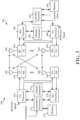
- the base station 102 in communication with the UE 104 in the access network 100 may include a variety of hardware components for performing the communications described herein.
- IP packets from the EPC 160 may be provided to a controller/processor 375.
- the controller/processor 375 implements layer 3 and layer 2 functionality.
- Layer 3 includes a radio resource control (RRC) layer
- layer 2 includes a service data adaptation protocol (SDAP) layer, a packet data convergence protocol (PDCP) layer, a radio link control (RLC) layer, and a medium access control (MAC) layer.
- RRC radio resource control
- SDAP service data adaptation protocol
- PDCP packet data convergence protocol
- RLC radio link control
- MAC medium access control
- the controller/processor 375 provides RRC layer functionality associated with broadcasting of system information (e.g, MIB, SIBs), RRC connection control (e.g., RRC connection paging, RRC connection establishment, RRC connection modification, and RRC connection release), inter radio access technology (RAT) mobility, and measurement configuration for UE measurement reporting; PDCP layer functionality associated with header compression / decompression, security (ciphering, deciphering, integrity protection, integrity verification), and handover support functions, RLC layer functionality associated with the transfer of upper layer packet data units (PDUs), error correction through ARQ, concatenation, segmentation, and reassembly of RLC service data units (SDDs), re-segmentation of RLC data PDUs, and reordering of RLC data PDUs; and MAC layer functionality associated with mapping between logical channels and transport channels, multiplexing of MAC SDUs onto transport blocks (TBs), demultiplexing of MAC SDUs from TBs, scheduling information reporting, error correction through
- the transmit (TX) processor 316 and the receive (RX) processor 370 implement layer 1 functionality associated with various signal processing functions.
- Layer 1 which includes a physical (PHY) layer, may include error detection on the transport channels, forward error correction (FEC) coding/decoding of the transport channels, interleaving, rate matching, mapping onto physical channels, modulation/demodulation of physical channels, and MIMO antenna processing.
- the TX processor 316 handles mapping to signal constellations based on various modulation schemes (e.g., binary phase-shift keying (BPSK), quadrature phase-shift keying (QPSK), M-phase-shift keying (M-PSK), M-quadrature amplitude modulation (M-QAM)).
- BPSK binary phase-shift keying
- QPSK quadrature phase-shift keying
- M-PSK M-phase-shift keying
- M-QAM M-quadrature amplitude modulation
- Each stream may then be mapped to an OFDM subcarrier, multiplexed with a reference signal (e.g., pilot) in the time and/or frequency domain, and then combined together using an Inverse Fast Fourier Transform (IFFT) to produce a physical channel carrying a time domain OFDM symbol stream.
- the OFDM stream is spatially precoded to produce multiple spatial streams.
- Channel estimates from a channel estimator 374 may be used to determine the coding and modulation scheme, as well as for spatial processing.
- the channel estimate may be derived from a reference signal and/or channel condition feedback transmitted by the UE 104.
- Each spatial stream may then be provided to a different antenna 320 via a separate transmitter 318TX.
- Each transmitter 318TX may modulate an RF carrier with a respective spatial stream for transmission.
- each receiver 354RX receives a signal through its respective antenna 352.
- Each receiver 354RX recovers information modulated onto an RF carrier and provides the information to the receive (RX) processor 356.
- the TX processor 368 and the RX processor 356 implement layer 1 functionality associated with various signal processing functions.
- the RX processor 356 may perform spatial processing on the information to recover any spatial streams destined for the UE 104. If multiple spatial streams are destined for the UE 104, they may be combined by the RX processor 356 into a single OFDM symbol stream.
- the RX processor 356 then converts the OFDM symbol stream from the time-domain to the frequency domain using a Fast Fourier Transform (FFT).
- FFT Fast Fourier Transform
- the frequency domain signal comprises a separate OFDM symbol stream for each subcarrier of the OFDM signal.
- the symbols on each subcarrier, and the reference signal are recovered and demodulated by determining the most likely signal constellation points transmitted by the base station 102. These soft decisions may be based on channel estimates computed by the channel estimator 358.
- the soft decisions are then decoded and deinterleaved to recover the data and control signals that were originally transmitted by the base station 102 on the physical channel.
- the data and control signals are then provided to the controller/processor 359, which implements layer 3 and layer 2 functionality.
- the controller/processor 359 can be associated with a memory 360 that stores program codes and data.
- the memory 360 may be referred to as a computer-readable medium.
- the controller/processor 359 provides demultiplexing between transport and logical channels, packet reassembly, deciphering, header decompression, and control signal processing to recover IP packets from the EPC 160.
- the controller/processor 359 is also responsible for error detection using an ACK and/or NACK protocol to support HARQ operations.
- the controller/processor 359 provides RRC layer functionality associated with system information (e.g., MIB, SIBs) acquisition, RRC connections, and measurement reporting, PDCP layer functionality associated with header compression / decompression, and security (ciphering, deciphering, integrity protection, integrity verification); RLC layer functionality associated with the transfer of upper layer PDUs, error correction through ARQ, concatenation, segmentation, and reassembly of RLC SDUs, re-segmentation of RLC data PDUs, and reordering of RLC data PDUs; and MAC layer functionality associated with mapping between logical channels and transport channels, multiplexing of MAC SDUs onto TBs, demultiplexing of MAC SDUs from TBs, scheduling information reporting, error correction through HARQ, priority handling, and logical channel prioritization.
- RRC layer functionality associated with system information (e.g., MIB, SIBs) acquisition, RRC connections, and measurement reporting
- PDCP layer functionality associated with header compression
- Channel estimates derived by a channel estimator 358 from a reference signal or feedback transmitted by the base station 102 may be used by the TX processor 368 to select the appropriate coding and modulation schemes, and to facilitate spatial processing.
- the spatial streams generated by the TX processor 368 may be provided to different antenna 352 via separate transmitters 354TX. Each transmitter 354TX may modulate an RF carrier with a respective spatial stream for transmission.
- the UL transmission is processed at the base station 102 in a manner similar to that described in connection with the receiver function at the UE 104.
- Each receiver 318RX receives a signal through its respective antenna 320.
- Each receiver 318RX recovers information modulated onto an RF carrier and provides the information to a RX processor 370.
- the controller/processor 375 can be associated with a memory 376 that stores program codes and data.
- the memory 376 may be referred to as a computer-readable medium.
- the controller/processor 375 provides demultiplexing between transport and logical channels, packet reassembly, deciphering, header decompression, control signal processing to recover IP packets from the UE 104. IP packets from the controller/processor 375 may be provided to the EPC 100.
- the controller/processor 375 is also responsible for error detection using an ACK and/or NACK protocol to support HARQ operations.
- At least one of the TX processor 368, the RX processor 356, and the controller/processor 359 may be configured to perform aspects in connection with communication component 140 ( FIG. 1 ) as described herein.
- At least one of the TX processor 316, the RX processor 370, and the controller/processor 375 may be configured to perform aspects in connection with communication component 141 ( FIG. 1 ) as described herein.
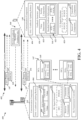
- an example cross-carrier scheduling scenario 400 includes the base station 102 and the UE 104 having established communications on multiple component carriers (CCs) 402 and utilizing one or more DAI / codebook updating rules 404 to enable the base station 102 to transmit the single DCI 147 to schedule DL signals 149, 151 for receipt by the UE 104 on each of the multiple CCs 402.
- CCs component carriers
- DAI / codebook updating rules 404 to enable the base station 102 to transmit the single DCI 147 to schedule DL signals 149, 151 for receipt by the UE 104 on each of the multiple CCs 402.
- the DCI 147 includes DAI information 145 that is updated according to one or more DAI / codebook updating rules 404 to enable the UE 104 to identify specific feedback relative the status of the receipt of the DL signals 149, 151, e.g., PDSCH 1 and PDSCH 2 , scheduled by the single DCI 147 on each of the multiple CCs 402.
- the DAI information 145 includes, but is not limited to, a counter-DAI (C-DAI) value or index and/or a total-DAI counter or index, which may be respective fields in the DAI information 145.
- the C-DAI value indicates the accumulative number of ⁇ serving cell, PDCCH monitoring occasion ⁇ -pair(s) in which PDSCH reception(s) or SPS PDSCH release is present, up to the current serving cell and current PDCCH monitoring occasion.
- the T-DAI value when present, indicates the total number of ⁇ serving cell, PDCCH monitoring occasion ⁇ -pair(s) in which PDSCH reception(s) or SPS PDSCH release is present, up to the current PDCCH monitoring occasion and is updated from PDCCH monitoring occasion to the PDCCH monitoring occasion.
- the C-DAI value and/or T-DAI value may be explicitly signaled, or in some cases one of more of the C-DAI values and/or T-DAI values may be implicitly signaled, as is explained below.
- the cross-carrier scheduling scenario 400 includes the UE 104 transmitting bundled feedback information 144, configured according to one or more DAI / codebook updating rules 404, to the base station 102 in response to receiving the DL signals 149, 151 scheduled by the single DCI 147 on each of the multiple CCs 402.
- the base station 102 may then re-transmit unsuccessfully received or unsuccessfully decoded ones of the signals 149, 151 based on the indications provided by the bundled feedback information 144.
- current DAI and codebook updating rules are not configured to account for a case of a single DCI scheduling PDSCH for multiple CCs.
- current solutions cannot properly account for the scheduling of multiple CCs by a single DCI, thereby leading to inaccurate feedback or an inability to efficiently perform cross-carrier scheduling and/or dynamic spectrum sharing.
- the one or more DAI / codebook updating rules 404 are configured to enable this cross-carrier scheduling and/or dynamic spectrum sharing by providing a mechanism for accurate feedback reporting in an simple and efficient manner.
- the one or more DAI / codebook updating rules 404 may instruct the base station 102 to update the DAI information 145 in the DCI 147 based on the following options:
- C-DAI and/or T-DAI values signaled in the DCI are increased by one per CC, e.g., n (number of the multiple CCs) in total; or
- Option 2 C-DAI and/or T-DAI values signaled in the DCI are increased by one.
- the one or more DAI / codebook updating rules 404 may instruct the UE 104 to update the bundled feedback information 144, e.g., the HARQ-ACK in the PUCCH codebook, based on the following option:
- Each scheduled CC per detected DCI is counted by UE as one position for the HARQ-ACK bit(s) of the corresponding scheduled PDSCH in the PUCCH codebook.
- the HARQ-ACK positions are first sorted based on ascending order of scheduled CC index (e.g., CC1 then CC2 and so on) in the same PDCCH monitoring occasion, then based on ascending order of PDCCH monitoring occasion index.
- the multiple component carriers (CCs) 402 may be any plurality of CCs, e.g., up to n where n is a positive integer.
- the base station 102 and UE 104 may operate their respective communication components 141, 140, according to one or more communication protocols 502 that may instantiate, for example, one or more protocols stacks on each of the base station 102 and the UE 104 configured to initiate or define one or more of the components described herein and/or perform the functionality described herein, and to communicate with each other over a wireless and/or wired network.
- each single DCI 147 may include a plurality of control information 506 (e.g., in FIG. 5 , Control Info CC1 up to Control Info CCn , wherein n is a positive integer), where the control information identifies the scheduled resources, e.g., one or more time/frequency resource blocks, for the UE 104 to monitor to receive a DL signal.
- control information 506 e.g., in FIG. 5 , Control Info CC1 up to Control Info CCn , wherein n is a positive integer
- the control information identifies the scheduled resources, e.g., one or more time/frequency resource blocks, for the UE 104 to monitor to receive a DL signal.
- the single DCI 147 may be triggered, for example, by a scheduler component 504 that receives data packets for delivery to the UE 104 and/or that generates control signaling identify, for example, reserved UL or DL resources, to configure the UE 104.
- the DL signal generator 406 may additionally be configured to generate the DL signals 149, 151, such as one or more PDSCHs, to convey the data packets the UE 104.
- the generation of the single DCI 147 may be triggered by other events, such as but not limited to new radio resource configurations, and/or retransmission of DL signals such as may be indicated by re-transmission controller 410.
- the re-transmission controller 410 may include an ACK/NACK manager component 508 that keeps track of the status of receipt of DL signals, as is explained below.
- the base station 104 and/or the communication component 141 may execute a DAI generator 408, associated with the DAI indication component 143, configured to generate the DAI information 145 to be included in each single DCI 147 that schedules multiple CCs 402.
- the DAI generator 408 is configured to operate an indexer component 510 to update the C-DAI value 409 and/or the T-DAI value 411 according to the one or more DAI / codebook updating rules 404, and provide such values to the DL signal generator 406 for including in the corresponding single DCI 147.
- the base station 102 and/or the communication component 141 and/or the re-transmission controller 410 may execute a decoder/sorter component 512 on the received bundled feedback information 144 or PUCCH codebook to parse the data and identify the specific feedback indications.
- re-transmission controller 410 is configured to receive an UL signal including the bundled feedback information 144 or PUCCH codebook, such as on a PUCCH, and decode the bundled feedback information 144 based on the one or more DAI / codebook updating rules 404 in order to interpret HARQ ACKS/NACKS for specific DL signals, and thereby determine whether or not to call for a re-transmission of a DL signal.
- re-transmission controller 410 may execute the decoder/sorter component 512 to decode and parse the bundled feedback information 144 to identify the specific feedback values.
- the ACK/NACK manager component 508 may then keep track of the status of receipt of UL signals, for instance, using one or more HARQ processes 514, which based on HARQ processing rules may be configured to generate a request for a re-transmission of a DL signal
- the information in the received UL signal(s) may be further processed by the communication component 141 and/or the base station 102, for example, to clear a DL queue, or inform the scheduler component 504.
- the base station 102 and/or the communication component 141 may execute a receiver component 412 to receive the communications described herein, and a transmitter component 414 to transmit the communications described herein.
- the receiver component 412 and the transmitter component 414 may be interfaces to/from the communications component 141 and/or they may be associated with a transmitter or receiver, respectively, or a transceiver.
- the communication component 141 of the base station 102 as described herein may be implemented by at least one of the TX processor 316, the RX processor 370, and the controller/processor 375 of FIG. 3 .
- the UE 104 operates the communication component 140 in communication with the base station 104, executing the ACK/NACK feedback indication component 142 according to the one or more DAI / codebook updating rules 404, to generate the bundled feedback information 144 based on the DAI information 145 from the DCI 147 and in response to receipt of the plurality of DL signals, e.g., DL signal CC1 149 up to DL signal CCn 151, on the multiple CCs 402.
- the feedback may include, for example, an acknowledgement (ACK) or a negative acknowledgement (NACK) of each respective DL signal.
- the UE 104 and/or the communication component 140 and/or the ACK/NACK feedback indication component 142 may execute a DL signal processor 602 to receive and process the DCI 147 and the multiple DL signals 149, 151. Further, the DL signal processor 602 may execute a decoder/index identifier component 604 to attempt to parse the corresponding DAI information 145 from the DCI 147 and attempt to decode the received DL signals 149, 151 and track a successful or unsuccessful decoding result based on the DAI information 145 and the one or more DAI / codebook updating rules 404.
- the DL signal processor 602 may then communicate with a feedback generator component 416, and in particular with one or more HARQ processes 606, to track the status of the received DL signals 149, 151.
- the feedback generator 416 operates a feedback value determiner 418 in combination with a sorting component 420 to utilize the results of the processing by the DL signal processor 602 and HARQ processes 606, in combination with the one or more DAI / codebook updating rules 404, to determine an order and/or position of the specific feedback values 422 indicated in the bundled feedback information 144.
- each specific feedback value 422 may be indicated by a bit or bits, where one value indicates successful receipt and decoding, e.g., an ACK, whereas a different value indicates unsuccessful receipt and/or decoding, e.g., a NACK.
- this particular formatting and/or positioning of the feedback enables the base station 102 to accurately identify and correlate the specific feedback contained in the bundled feedback information 144 for each of the plurality of transmitted DL signals 149, 151 scheduled by the single DCI 147 on each of the multiple CCs 402.
- the UE 104 and/or communication component 140 includes an UL signal generator 424 configured to generate one or more UL signals, including the bundled feedback information 144 as generated by the feedback generator 416.
- the UL signal generator 424 may also generate other UL control and/or data signals, such as a PDSCH to carry data generated by the UE 104 for transmission to the base station 102 or another device directly or indirectly in communication with the UE 102 over a wired or wireless network.
- the UL signal generator 424 may receive data packets from one or more applications 608 executing on the UE 104.
- the UE 104 and/or the communication component 140 may execute a receiver component 426 to receive the communications described herein, and a transmitter component 428 to transmit the communications described herein.
- the receiver component 426 and the transmitter component 428 may be interfaces to/from the communications component 140 and/or they may be associated with a transmitter or receiver, respectively, or a transceiver,
- the communication component 140 of the UE 104 as described herein may be implemented by at least one of the TX processor 368, the RX processor 356, and the controller/processor 359 of FIG. 3 .
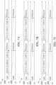
- examples of signaling scenarios 700, 730, and 750 represent cases where different variations in the DAI / codebook updating rules 404 are used, and all include updating at least one of the counter DAI or the total DAI in the DCI by a value that is incremented by at least 1 or by a number of the multiple component carriers scheduled by a previous DCI.
- the base station 102 is indicated as gNB and the multiple component carriers are indicated as Cell 1 and Cell 2.
- both of the counter DAI and the total DAI in the DCI have respective values that are incremented by a number of the at least two component carriers from a previous DCI. For instance, since DCI1 is the first DCI and it schedules both the first component carrier (CC1, or, Cell 1 as illustrated), the counter DAI is initially set with a value of 0 and the total DAI value is set to include the number of scheduled PDSCHs, e.g., 2 in this case.
- the subsequent DCI2 therefore increments the counter DAI by 2 based on the number of PDSCHs previously scheduled, and the total DAI value is incremented add the number of previously scheduled PDSCHs, e.g., PDSCH1 and PDSCH2, to the number of currently scheduled PDSCHs, e.g., PDSCH3 and PDSCH4, and thus is incremented from 2 to 4 in this case.
- the counter DAI in each subsequent DCI is incremented by 1, whereas the total DAI is incremented by the number of component carriers scheduled by the previous DCI.
- both the counter DAI and the total DAI are incremented by at least 1 from a previous DCI.
- the total DAI is initially set at a value of 1 since the incrementing is only by 1 and not by the number of component carriers scheduled
- examples of signaling scenarios 800, 830, and 850 represent cases where different variations in the DAI / codebook updating rules 404 are used, and all include using multiple values for one or both of the counter DAI and the total DAI, as well as updating at least one of the multiple values of the counter DAI or the total DAI in the DCI by a value that is incremented by at least 1 or by a number of the multiple component carriers scheduled by a previous DCI.
- the base station 102 is indicated as gNB and the multiple component carriers are indicated as Cell 1 and Cell 2.
- the counter DAI includes a value for each of the at least two component carriers and the total DAI is incremented by a number of the at least two component carriers from a previous DCI.
- the counter DAI is initially set as (0,1) to correspond to scheduled PDSCH1 and PDSCH2, and the total DAI is set to 2 to correspond to the total number of PDSCHs scheduled
- the total DAI is set to 4 to correspond to the total number of PDSCHs scheduled.
- the DAI includes paired counter DAI and total DAI values for each of the multiple component carriers scheduled, where each counter DAI includes a value for each of the multiple component carriers and the total DAI includes a value for each of the multiple component carriers, wherein the paired counter DAI and total DAI values for a corresponding component carrier are each incremented by 1 when a subsequent DCI schedules a subsequent PDSCH for the corresponding component carrier.
- the counter DAI includes a value for a single component carrier of the multiple component carriers selected by a rule, and the total DAI is incremented by a number of the multiple component carriers scheduled, where the counter DAI value for one or more remaining ones of the multiple component carriers is implicitly indicated or determined based on the rule and the number of the multiple component carriers.
- the rule dictates that the component carrier having the highest index, e.g., component carrier 2 (or Cell 2) in this case, receives the explicit DAI information.
- the UE 104 can determine the DAI information for the remaining component carriers, e.g., component carrier 1 (or Cell 1) in this case, by further applying the portion of the rule that dictates that the counter DAI and the total DAI are each incremented by a number of the multiple component carriers scheduled.
- component carrier 1 or Cell 1
- examples of signaling scenarios 900 and 930 represent cases where different variations in the DAI / codebook updating rules 404 are used, and each include multiple PDCCH monitoring occasions in which one or more DCIs may be transmitted by the base station 104 and received by the UE 104.
- these scenarios include updating at least one of the counter DAI or the total DAI in the DCI by a value that is incremented by a number of the multiple component carriers scheduled by a previous DCI.
- these scenarios include transmitting the bundled feedback information 144 in the form of a physical uplink control channel (PUCCH) including a position for hybrid automatic repeat request (HARQ)-Acknowledgement (ACK) bits corresponding to the PDSCH for each of the multiple component carriers.
- PUCCH physical uplink control channel
- HARQ hybrid automatic repeat request
- ACK Acknowledgement
- a single DCI is received in each monitoring occasion, and the feedback is ordered based on the component carrier index per monitoring occasion.
- the UE 104 generates and transmits the PUCCH by sorting the HARQ-ACK bits corresponding to the PDSCH for each of the multiple component carriers first in ascending order of scheduled component carrier index within each PDCCH monitoring occasion, then in ascending order of PDCCH monitoring occasion index.
- scenario 930 two DCIs are received in a first monitoring occasion, and a single DCI is received in a second monitoring occasion, but two of the scheduled PDSCHs are not received by the UE 104. Specifically, PDSCH3 and PDSCH4 scheduled by DCI3 are not received by the UE 104.
- the UE 104 sorts the HARQ-ACK bits corresponding to the PDSCHs for each of the multiple component carriers in ascending order of scheduled component carrier index, including sorting the HARQ-ACK bits in ascending order of a corresponding counter DAI value.
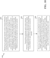
- an example of a method 1000 of wireless communication performed by the UE 104 may be used in a scenario where a single DCI schedules multiple component carriers.
- the UE 104 may perform method 800 by executing communication component 140 or one or more subcomponents thereof, and/or via execution of at least one of the TX processor 368, the RX processor 356, and/or the controller/processor 359, as discussed above. Specifics of the actions or features of each portion of the method 1000 are described above in detail.
- the method 1000 includes receiving on a physical downlink control channel (PDCCH) during a first PDCCH monitoring occasion a first downlink control information (DCI) that schedules a physical downlink shared channel (PDSCH) for each of at least two component carriers, wherein the DCI includes a counter downlink assignment index (DAI) that indicates a number of scheduled PDSCHs up to a point that the first DCI was received and a total DAI indicating a number of scheduled PDSCHs across the at least two component carriers.
- DCI downlink control information
- DAI counter downlink assignment index
- the C-DAI value indicates the accumulative number of ⁇ serving cell, PDCCH monitoring occasion ⁇ -pair(s) in which PDSCH reception(s) or SPS PDSCH release is present, up to the current serving cell and current PDCCH monitoring occasion.
- the T-DAI value when present, indicates the total number of ⁇ serving cell, PDCCH monitoring occasion ⁇ -pair(s) in which PDSCH reception(s) or SPS PDSCH release is present, up to the current PDCCH monitoring occasion and is updated from PDCCH monitoring occasion to the PDCCH monitoring occasion.
- At least one of the counter DAI or the total DAI in the DCI has a value that is incremented by a number of the at least two component carriers from a previous DCI.
- both of counter DAI and the total DAI in the DCI have respective values that are incremented by a number of the at least two component carriers from a previous DCI.
- both the counter DAI and the total DAI are incremented by 1 from a previous DCI
- the counter DAI includes a value for each of the at least two component carriers and the total DAI is incremented by a number of the at least two component carriers from a previous DCI.
- the counter DAI includes a value for each of the at least two component carriers and the total DAI includes a value for each of the at least two component carriers, wherein a DAI for a means for corresponding component carrier is incremented by 1 when the DCI schedules a PDSCH for the corresponding component carrier.
- the counter DAI includes a value for a single component carrier of the at least two component carriers selected by a rule and the total DAI is incremented by a number of the at least two component carriers, further comprising means for determining a counter DAI value for another of the at least two component carriers based on the rule and the number of the at least two component carriers
- the method 1000 includes transmitting a physical uplink control channel (PUCCH) including a position for hybrid automatic repeat request (HARQ)-Acknowledgement (ACK) bits corresponding to the PDSCH for each of the at least two component carriers.
- PUCCH physical uplink control channel
- HARQ hybrid automatic repeat request
- ACK Acknowledgement
- sorting the HARQ-ACK bits corresponding to the PDSCH for each of the at least two component carriers in ascending order of scheduled component carrier index comprises sorting the HARQ-ACK bits in ascending order of a corresponding counter DAI value
- FIG. 11 is a flowchart 1100 of a method of wireless communication at the base station 102 may be used in a scenario where a single DCI schedules multiple component carriers.
- the base station 102 may perform the method 1100 by executing communication component 141 or one or more subcomponents thereof, and/or via execution of at least one of the TX processor 316, the RX processor 370, and/or the controller/processor 375, as discussed above. Specifics of the actions or features of each portion of the method 1000 are described above in detail.
- the method 1100 includes transmitting on a physical downlink control channel (PDCCH) during a first PDCCH monitoring occasion a first downlink control information (DCI) that schedules a physical downlink shared channel (PDSCH) for each of at least two component carriers, wherein the DCI includes a counter downlink assignment index (DAI) that indicates a number of scheduled PDSCHs up to a point that the first DCI was received and a total DAI indicating a number of scheduled PDSCHs across the at least two component carriers.
- DCI downlink control information
- DAI counter downlink assignment index
- the C-DAI value indicates the accumulative number of ⁇ serving cell, PDCCH monitoring occasion ⁇ -pair(s) in which PDSCH receptioti(s) or SPS PDSCH release is present, up to the current serving cell and current PDCCH monitoring occasion.
- the T-DAI value when present, indicates the total number of ⁇ serving cell, PDCCH monitoring occasion ⁇ -pair(s) in which PDSCH reception(s) or SPS PDSCH release is present, up to the current PDCCH monitoring occasion and is updated from PDCCH monitoring occasion to the PDCCH monitoring occasion.
- the method 1100 includes receiving a physical uplink control channel (PUCCH) including a position for hybrid automatic repeat request (HARQ)-Acknowledgement (ACK) bits corresponding to the PDSCH for each of the at least two component carriers.
- PUCCH physical uplink control channel
- HARQ hybrid automatic repeat request
- ACK Acknowledgement
- At least one of the counter DAI or the total DAI in the DCI has a value that is incremented by a number of the at least two component carriers from a previous DCI.
- both of counter DAI and the total DAI in the DCI have respective values that are incremented by a number of the at least two component carriers from a previous DCI.
- both the counter DAI and the total DAI are incremented by 1 from a previous DCI.
- the counter DAI includes a value for each of the at least two component carriers and the total DAI is incremented by a number of the at least two component carriers from a previous DCI.
- the counter DAI includes a value for each of the at least two component carriers and the total DAI includes a value for each of the at least two component carriers, wherein a DAI for a means for corresponding component carrier is incremented by 1 when the DCI schedules a PDSCH for the corresponding component carrier.
- the counter DAI includes a value for a single component carrier of the at least two component carriers selected by a rule and the total DAI is incremented by a number of the at least two component carriers, further comprising means for determining a counter DAI value for another of the at least two component carriers based on the rule and the number of the at least two component carriers.
- any of the preceding aspects of the method 1100 may include transmitting a second DCI in a second PDCCH monitoring occasion, wherein receiving the PDCCH comprises sorting the HARQ-ACK bits corresponding to the PDSCH for each of the at least two component carriers first in ascending order of scheduled component carrier index within each PDCCH monitoring occasion, then in ascending order of PDCCH monitoring occasion index.
- sorting the HARQ-ACK bits corresponding to the PDSCH for each of the at least two component carriers in ascending order of scheduled component carrier index comprises sorting the HARQ-ACK bits in ascending order of a corresponding counter DAI value.
- the UE 104 and/or the base station 102 may include additional components that perform each of the blocks of the algorithm in the aforementioned flowcharts. As such, each block in the aforementioned flowcharts may be performed by a component and the UE 104 and/or the base station 102 may include one or more of those components.
- the components may be one or more hardware components specifically configured to carry out the stated processes/algorithm, implemented by a processor configured to perform the stated processes/algorithm, stored within a computer-readable medium for implementation by a processor, or some combination thereof.
- Combinations such as "at least one of A, B, or C,” “one or more of A, B, or C,” “at least one of A, B, and C,” “one or more of A, B, and C,” and "A, B, C, or any combination thereof” include any combination of A, B, and/or C, and may include multiples of A, multiples of B, or multiples of C.
- combinations such as “at least one of A, B, or C,” “one or more of A, B, or C,” “at least one of A, B, and C,” “one or more of A, B, and C,” and “A, B, C, or any combination thereof” may be A only, B only, C only, A and B, A and C, B and C, or A and B and C, where any such combinations may contain one or more member or members of A, B, or C.
- the scope of protection is defined by the appended claims. Moreover, nothing disclosed herein is intended to be dedicated to the public regardless of whether such disclosure is explicitly recited in the claims.
Landscapes
- Engineering & Computer Science (AREA)
- Signal Processing (AREA)
- Computer Networks & Wireless Communication (AREA)
- Mobile Radio Communication Systems (AREA)
Claims (15)
- Ein Verfahren (1000) zur drahtlosen Kommunikation an einer Benutzereinrichtung bzw. UE (user equipment) (104), das umfasst:Empfangen (1002), von einer Basisstation, auf einem physikalischen Abwärtsstrecke- bzw. Downlink-Steuerkanal bzw. PDCCH (physical downlink control channel), während einer ersten PDCCH-Überwachungsgelegenheit, einer ersten Downlink-Steuerinformation bzw. DCI (downlink control information), die einen Physical Downlink Shared Channel bzw. PDSCH für jeden von zumindest zwei Komponententrägern plant, wobei die erste DCI einen Zähler-Downlink-Zuweisungsindex bzw. -DAI (downlink assignment index) umfasst, der eine Anzahl geplanter PDSCHs über die zumindest zwei Komponententräger bis zu einem Punkt angibt, an dem die erste DCI empfangen wurde, und einen Gesamt-DAI, der eine Anzahl geplanter PDSCHs über die zumindest zwei Komponententräger angibt;Aktualisieren, unter Bezugnahme auf in einem Codebuch konfigurierte Regeln, gebündelter Rückmeldungs- bzw. Feedback-Information, basierend auf dem Zähler-DAI und dem Gesamt-DAI in der empfangenen ersten DCI und in Reaktion auf den Empfang der geplanten PDSCHs durch die UE; undÜbertragen (1004), an die Basisstation, der gebündelten Rückmeldungsinformation, die in einem physikalischen Aufwärtsstrecke- bzw. Uplink-Steuerkanal bzw. PUCCH (physical uplink control channel) enthalten ist, wobei die gebündelte Rückmeldungsinformation konfiguriert ist, um eine Position für hybrideautomatische-Wiederholungsanforderung- bzw. HARQ(hybrid automatic repeat request)-Bestätigungs- bzw. ACK(Acknowledgement)-Bits aufzunehmen, die dem PDSCH für jeden der zumindest zwei Komponententräger entsprechen.
- Das Verfahren gemäß Anspruch 1, wobei zumindest einer des Zähler-DAI oder des Gesamt-DAI in der DCI einen Wert hat, der um eine Anzahl der zumindest zwei Komponententräger von einer vorherigen DCI inkrementiert wird.
- Das Verfahren gemäß Anspruch 1, wobei sowohl der Zähler-DAI als auch der Gesamt-DAI in der DCI jeweilige Werte haben, die um eine Anzahl der zumindest zwei Komponententräger von einer vorherigen DCI inkrementiert werden.
- Das Verfahren gemäß Anspruch 1, wobei sowohl der Zähler-DAI als auch der Gesamt-DAI von einer vorherigen DCI um 1 inkrementiert werden.
- Das Verfahren gemäß Anspruch 1, wobei der Zähler-DAI einen Wert für jeden der zumindest zwei Komponententräger umfasst und der Gesamt-DAI um eine Anzahl der zumindest zwei Komponententräger von einer vorherigen DCI inkrementiert wird.
- Das Verfahren gemäß Anspruch 1, wobei der Zähler-DAI einen Wert für jeden der zumindest zwei Komponententräger umfasst und der Gesamt-DAI einen Wert für jeden der zumindest zwei Komponententräger umfasst, wobei ein DAI für einen entsprechenden Komponententräger um 1 inkrementiert wird, wenn die DCI einen PDSCH für den entsprechenden Komponententräger plant.
- Das Verfahren gemäß Anspruch 1, wobei der Zähler-DAI einen Wert für einen einzelnen Komponententräger der zumindest zwei Komponententräger umfasst, der durch eine Regel ausgewählt wird, und der Gesamt-DAI um eine Anzahl der zumindest zwei Komponententräger inkrementiert wird, weiter umfassend ein Bestimmen eines Zähler-DAI-Werts für einen anderen der zumindest zwei Komponententräger basierend auf der Regel und der Anzahl der zumindest zwei Komponententräger.
- Das Verfahren gemäß Anspruch 1, das weiter umfasst: Empfangen, von der Basisstation, einer zweiten DCI in einer zweiten PDCCH-Überwachungsgelegenheit, wobei das Übertragen des PUCCH ein Sortieren von HARQ-ACK-Bits entsprechend dem PDSCH für jeden der zumindest zwei Komponententräger zuerst in aufsteigender Reihenfolge des geplanten Komponententrägerindexes innerhalb jeder PDCCH-Überwachungsgelegenheit, dann in aufsteigender Reihenfolge des PDCCH-Überwachungsgelegenheitsindexes umfasst.
- Das Verfahren gemäß Anspruch 8, wobei das Sortieren der HARQ-ACK-Bits entsprechend dem PDSCH für jeden der zumindest zwei Komponententräger in aufsteigender Reihenfolge des geplanten Komponententrägerindexes ein Sortieren der HARQ-ACK-Bits in aufsteigender Reihenfolge eines entsprechenden Zähler-DAI-Werts umfasst.
- Eine Vorrichtung an einer Benutzereinrichtung bzw. UE (104) zur drahtlosen Kommunikation, die umfasst:einen Prozessor (356, 359, 368); undeinen Speicher (360), der mit dem Prozessor (356, 359, 368) in Verbindung steht und Anweisungen speichert, die bei Ausführung durch den Prozessor (356, 359, 368) die Vorrichtung veranlassen, das Verfahren gemäß einem der Ansprüche 1 - 9 auszuführen.
- Ein Verfahren (1100) zur drahtlosen Kommunikation an einer Basisstation (102), das umfasst:Übertragen (1102), an eine Benutzereinrichtung bzw. UE, auf einem physikalischen Abwärtsstrecke- bzw. Downlink-Steuerkanal bzw. PDCCH, während einer ersten PDCCH-Überwachungsgelegenheit, einer ersten Downlink-Steuerinformation bzw. DCI, die einen Physical Downlink Shared Channel bzw.PDSCH für jeden von zumindest zwei Komponententrägern plant, wobei die erste DCI einen Zähler-Downlink-Zuweisungsindex bzw. -DAI umfasst, der eine Anzahl geplanter PDSCHs über die zumindest zwei Komponententräger bis zu einem Punkt angibt, an dem die erste DCI gesendet wurde, und einen Gesamt-DAI, der eine Anzahl geplanter PDSCHs über die zumindest zwei Komponententräger angibt, wobei der Zähler-DAI und der Gesamt-DAI unter Bezugnahme auf in einem ersten Codebuch konfigurierte Regeln aktualisiert werden; undEmpfangen (1104), von der UE, von gebündelter Rückmeldungsinformation, die in einem physikalischen Aufwärtsstrecke- bzw. Uplink-Steuerkanal bzw. PUCCH enthalten ist, wobei die gebündelte Rückmeldungsinformation konfiguriert ist, um eine Position für hybride-automatische-Wiederholungsanforderung- bzw. HARQ-Bestätigungs- bzw. ACK-Bits aufzunehmen, die dem PDSCH für jeden der zumindest zwei Komponententräger entsprechen; und wobei die gebündelte Rückmeldungsinformation durch die UE unter Bezugnahme auf in einem zweiten Codebuch konfigurierte Regeln basierend auf dem Zähler-DAI und dem Gesamt-DAI in der empfangenen ersten DCI und in Reaktion auf den Empfang der geplanten PDSCHs durch die UE aktualisiert wird.
- Das Verfahren gemäß Anspruch 11, wobei:i. zumindest einer des Zähler-DAI oder des Gesamt-DAI in der DCI einen Wert hat, der um eine Anzahl der zumindest zwei Komponententräger von einer vorherigen DCI inkrementiert wird; oderii. sowohl der Zähler-DAI als auch der Gesamt-DAI in der DCI jeweilige Werte haben, die um eine Anzahl der zumindest zwei Komponententräger von einer vorherigen DCI inkrementiert werden; oderiii. sowohl der Zähler-DAI als auch der Gesamt-DAI um 1 von einer vorherigen DCI inkrementiert werden; oderiv. der Zähler-DAI einen Wert für jeden der zumindest zwei Komponententräger umfasst und der Gesamt-DAI um eine Anzahl der zumindest zwei Komponententräger von einer vorherigen DCI inkrementiert wird.
- Das Verfahren gemäß Anspruch 11, wobei:i. der Zähler-DAI einen Wert für jeden der zumindest zwei Komponententräger umfasst und der Gesamt-DAI einen Wert für jeden der zumindest zwei Komponententräger umfasst, wobei ein DAI für einen entsprechenden Komponententräger um 1 inkrementiert wird, wenn die DCI einen PDSCH für den entsprechenden Komponententräger plant; oderii. der Zähler-DAI einen Wert für einen einzelnen Komponententräger der zumindest zwei Komponententräger umfasst, der durch eine Regel ausgewählt wird, und der Gesamt-DAI um eine Anzahl der zumindest zwei Komponententräger inkrementiert wird, weiter umfassend ein Bestimmen eines Zähler-DAI-Werts für einen anderen der zumindest zwei Komponententräger basierend auf der Regel und der Anzahl der zumindest zwei Komponententräger.
- Das Verfahren gemäß Anspruch 11, das weiter umfasst: Übertragen, an die UE, einer zweiten DCI in einer zweiten PDCCH-Überwachungsgelegenheit, wobei das Empfangen des PUCCH ein Sortieren von HARQ-ACK-Bits entsprechend dem PDSCH für jeden der zumindest zwei Komponententräger zuerst in aufsteigender Reihenfolge des geplanten Komponententrägerindex innerhalb jeder PDCCH-Überwachungsgelegenheit, dann in aufsteigender Reihenfolge des PDCCH-Überwachungsgelegenheitsindexes umfasst, und wobei das Sortieren der HARQ-ACK-Bits entsprechend dem PDSCH für jeden der zumindest zwei Komponententräger in aufsteigender Reihenfolge des geplanten Komponententrägerindexes ein Sortieren der HARQ-ACK-Bits in aufsteigender Reihenfolge eines entsprechenden Zähler-DAI-Werts umfasst.
- Eine Vorrichtung an einer Basisstation (102) zur drahtlosen Kommunikation, die umfasst:einen Prozessor (316, 370, 375); undeinen Speicher (376), der mit dem Prozessor (316, 370, 375) in Verbindung steht und Anweisungen speichert, die bei Ausführung durch den Prozessor (316, 370, 375) die Vorrichtung veranlasst, das Verfahren gemäß einem der Ansprüche 11 bis 14 auszuführen.
Applications Claiming Priority (1)
| Application Number | Priority Date | Filing Date | Title |
|---|---|---|---|
| PCT/CN2020/072657 WO2021142755A1 (en) | 2020-01-17 | 2020-01-17 | DAI AND CODEBOOK UPDATING FOR DCI SCHEDULING MULTIPLE CCs |
Publications (3)
| Publication Number | Publication Date |
|---|---|
| EP4091256A1 EP4091256A1 (de) | 2022-11-23 |
| EP4091256A4 EP4091256A4 (de) | 2023-09-27 |
| EP4091256B1 true EP4091256B1 (de) | 2025-05-14 |
Family
ID=76863509
Family Applications (1)
| Application Number | Title | Priority Date | Filing Date |
|---|---|---|---|
| EP20913282.8A Active EP4091256B1 (de) | 2020-01-17 | 2020-01-17 | Dai- und codebuch-aktualisierung für dci-planung von mehreren ccs |
Country Status (4)
| Country | Link |
|---|---|
| US (1) | US12289168B2 (de) |
| EP (1) | EP4091256B1 (de) |
| CN (1) | CN114982176B (de) |
| WO (1) | WO2021142755A1 (de) |
Cited By (1)
| Publication number | Priority date | Publication date | Assignee | Title |
|---|---|---|---|---|
| US20240089963A1 (en) * | 2021-01-28 | 2024-03-14 | Mediatek Singapore Pte. Ltd. | Method and apparatus for cross-carrier scheduling in mobile communications |
Families Citing this family (8)
| Publication number | Priority date | Publication date | Assignee | Title |
|---|---|---|---|---|
| CN119697785A (zh) * | 2020-02-11 | 2025-03-25 | 中兴通讯股份有限公司 | 一种信息生成方法、设备和存储介质 |
| US11695512B2 (en) * | 2020-05-15 | 2023-07-04 | Qualcomm Incorporated | Downlink assignment index (DAI) updates for piggyback downlink control information (DCI) |
| CN113747588B (zh) * | 2020-05-28 | 2024-01-23 | 大唐移动通信设备有限公司 | 信息传输方法及装置 |
| WO2022029295A1 (en) * | 2020-08-07 | 2022-02-10 | Telefonaktiebolaget Lm Ericsson (Publ) | Dai and harq codebook for multi-cell scheduling |
| WO2022027551A1 (en) * | 2020-08-07 | 2022-02-10 | Lenovo (Beijing) Limited | Method and apparatus for harq-ack codebook determination for multi-carrier scheduling |
| US11558166B2 (en) | 2021-01-13 | 2023-01-17 | Qualcomm Incorporated | Assignment indexes for dynamic feedback |
| CN118077164A (zh) * | 2021-11-05 | 2024-05-24 | 联想(北京)有限公司 | 用于在pusch上多路复用harq-ack反馈的方法及设备 |
| WO2023092431A1 (zh) * | 2021-11-25 | 2023-06-01 | Oppo广东移动通信有限公司 | 无线通信的方法、终端设备以及网络设备 |
Family Cites Families (10)
| Publication number | Priority date | Publication date | Assignee | Title |
|---|---|---|---|---|
| US9042840B2 (en) | 2009-11-02 | 2015-05-26 | Qualcomm Incorporated | Cross-carrier/cross-subframe indication in a multi-carrier wireless network |
| WO2016162090A1 (en) | 2015-04-10 | 2016-10-13 | Nokia Solutions And Networks Oy | Enhanced carrier aggregation in communications |
| WO2017044066A1 (en) * | 2015-09-11 | 2017-03-16 | Intel IP Corporation | Transmission of uplink control information in wireless systems |
| CN111034087B (zh) * | 2017-08-11 | 2024-03-29 | 瑞典爱立信有限公司 | 具有不同处理时间的下行链路指配 |
| EP3679670A1 (de) * | 2017-09-08 | 2020-07-15 | Telefonaktiebolaget LM Ericsson (Publ) | Quittierungssignalisierung in einem funkzugangsnetz |
| CA3082758C (en) * | 2017-11-17 | 2023-01-17 | Telefonaktiebolaget Lm Ericsson (Publ) | Acknowledgement signaling for radio access networks |
| US11997045B2 (en) * | 2018-02-16 | 2024-05-28 | Nokia Technologies Oy | Hybrid automatic repeat request feedback arrangement for NR-unlicensed bands |
| MX2020007980A (es) * | 2018-04-06 | 2020-09-07 | Ericsson Telefon Ab L M | Control de potencia para se?alizacion de retroalimentacion. |
| US11177909B2 (en) * | 2018-05-04 | 2021-11-16 | Qualcomm Incorporated | Methods and apparatus related to ACK/NACK feedback with multi-TRP transmissions |
| WO2021100982A1 (ko) * | 2019-11-20 | 2021-05-27 | 엘지전자 주식회사 | Harq-ack 코드북을 전송하는 방법, 사용자기기, 장치 및 저장매체, harq-ack 코드북을 수신하는 방법 및 기지국 |
-
2020
- 2020-01-17 WO PCT/CN2020/072657 patent/WO2021142755A1/en not_active Ceased
- 2020-01-17 CN CN202080092751.4A patent/CN114982176B/zh active Active
- 2020-01-17 EP EP20913282.8A patent/EP4091256B1/de active Active
- 2020-01-17 US US17/788,669 patent/US12289168B2/en active Active
Cited By (2)
| Publication number | Priority date | Publication date | Assignee | Title |
|---|---|---|---|---|
| US20240089963A1 (en) * | 2021-01-28 | 2024-03-14 | Mediatek Singapore Pte. Ltd. | Method and apparatus for cross-carrier scheduling in mobile communications |
| US12550142B2 (en) * | 2021-01-28 | 2026-02-10 | Mediatek Singapore Pte. Ltd. | Method and apparatus for cross-carrier scheduling in mobile communications |
Also Published As
| Publication number | Publication date |
|---|---|
| US20230030642A1 (en) | 2023-02-02 |
| EP4091256A4 (de) | 2023-09-27 |
| WO2021142755A1 (en) | 2021-07-22 |
| EP4091256A1 (de) | 2022-11-23 |
| CN114982176A (zh) | 2022-08-30 |
| CN114982176B (zh) | 2024-03-05 |
| US12289168B2 (en) | 2025-04-29 |
Similar Documents
| Publication | Publication Date | Title |
|---|---|---|
| US11855780B2 (en) | Methods and apparatus related to ACK/NACK feedback with multi-TRP transmissions | |
| US11464001B2 (en) | Joint activation of multiple semi-persistent scheduling configurations in a single message | |
| EP4091256B1 (de) | Dai- und codebuch-aktualisierung für dci-planung von mehreren ccs | |
| US12408173B2 (en) | Uplink control information multiplexing | |
| US12193036B2 (en) | Time domain resource allocation-based HARQ-ACK feedback generation | |
| US11848780B2 (en) | Methods and apparatus to facilitate a HARQ flush indicator for transmissions | |
| WO2021147117A1 (en) | Enhanced harq-ack bundling for cbg based retransmission | |
| WO2022073181A1 (en) | Starting bit determination for pusch repetition with transport block size scaling | |
| US12034544B2 (en) | Methods and apparatus to facilitate a multiple bit new data indicator | |
| WO2021212028A1 (en) | Apparatus for transmitting a harq buffer flush indicator for code block transmissions | |
| US11838921B2 (en) | Multi-channel downlink scheduling with miss detection based on variable bitwidth index | |
| WO2021142760A1 (en) | Single dci updating operation parameters for multiple component carriers | |
| WO2021067508A1 (en) | Prioritization between a scheduling request and harq feedback | |
| US11811699B2 (en) | Full-duplex turbo HARQ-ACK | |
| US12452902B2 (en) | Building transport blocks in wireless networks | |
| US11979884B2 (en) | HARQ timing for multi-PDSCH grant | |
| US12238743B2 (en) | Acknowledgement of group common dci for MU-MIMO | |
| WO2022213239A1 (en) | Dummy indications in dci with unified tci indication | |
| WO2021159271A1 (en) | Intra-slot pdsch cbg repetition for harq retransmission | |
| EP3991331B1 (de) | Verfahren und vorrichtung zur erleichterung der schicht-1-querträgerwiederholung |
Legal Events
| Date | Code | Title | Description |
|---|---|---|---|
| STAA | Information on the status of an ep patent application or granted ep patent |
Free format text: STATUS: THE INTERNATIONAL PUBLICATION HAS BEEN MADE |
|
| PUAI | Public reference made under article 153(3) epc to a published international application that has entered the european phase |
Free format text: ORIGINAL CODE: 0009012 |
|
| STAA | Information on the status of an ep patent application or granted ep patent |
Free format text: STATUS: REQUEST FOR EXAMINATION WAS MADE |
|
| 17P | Request for examination filed |
Effective date: 20220616 |
|
| AK | Designated contracting states |
Kind code of ref document: A1 Designated state(s): AL AT BE BG CH CY CZ DE DK EE ES FI FR GB GR HR HU IE IS IT LI LT LU LV MC MK MT NL NO PL PT RO RS SE SI SK SM TR |
|
| DAV | Request for validation of the european patent (deleted) | ||
| DAX | Request for extension of the european patent (deleted) | ||
| A4 | Supplementary search report drawn up and despatched |
Effective date: 20230828 |
|
| RIC1 | Information provided on ipc code assigned before grant |
Ipc: H04B 7/04 20170101AFI20230822BHEP |
|
| GRAP | Despatch of communication of intention to grant a patent |
Free format text: ORIGINAL CODE: EPIDOSNIGR1 |
|
| STAA | Information on the status of an ep patent application or granted ep patent |
Free format text: STATUS: GRANT OF PATENT IS INTENDED |
|
| INTG | Intention to grant announced |
Effective date: 20241217 |
|
| GRAS | Grant fee paid |
Free format text: ORIGINAL CODE: EPIDOSNIGR3 |
|
| GRAA | (expected) grant |
Free format text: ORIGINAL CODE: 0009210 |
|
| STAA | Information on the status of an ep patent application or granted ep patent |
Free format text: STATUS: THE PATENT HAS BEEN GRANTED |
|
| AK | Designated contracting states |
Kind code of ref document: B1 Designated state(s): AL AT BE BG CH CY CZ DE DK EE ES FI FR GB GR HR HU IE IS IT LI LT LU LV MC MK MT NL NO PL PT RO RS SE SI SK SM TR |
|
| REG | Reference to a national code |
Ref country code: GB Ref legal event code: FG4D |
|
| REG | Reference to a national code |
Ref country code: CH Ref legal event code: EP |
|
| REG | Reference to a national code |
Ref country code: DE Ref legal event code: R096 Ref document number: 602020051436 Country of ref document: DE |
|
| REG | Reference to a national code |
Ref country code: IE Ref legal event code: FG4D |
|
| REG | Reference to a national code |
Ref country code: NL Ref legal event code: MP Effective date: 20250514 |
|
| PG25 | Lapsed in a contracting state [announced via postgrant information from national office to epo] |
Ref country code: PT Free format text: LAPSE BECAUSE OF FAILURE TO SUBMIT A TRANSLATION OF THE DESCRIPTION OR TO PAY THE FEE WITHIN THE PRESCRIBED TIME-LIMIT Effective date: 20250915 Ref country code: FI Free format text: LAPSE BECAUSE OF FAILURE TO SUBMIT A TRANSLATION OF THE DESCRIPTION OR TO PAY THE FEE WITHIN THE PRESCRIBED TIME-LIMIT Effective date: 20250514 Ref country code: ES Free format text: LAPSE BECAUSE OF FAILURE TO SUBMIT A TRANSLATION OF THE DESCRIPTION OR TO PAY THE FEE WITHIN THE PRESCRIBED TIME-LIMIT Effective date: 20250514 |
|
| REG | Reference to a national code |
Ref country code: LT Ref legal event code: MG9D |
|
| PG25 | Lapsed in a contracting state [announced via postgrant information from national office to epo] |
Ref country code: NO Free format text: LAPSE BECAUSE OF FAILURE TO SUBMIT A TRANSLATION OF THE DESCRIPTION OR TO PAY THE FEE WITHIN THE PRESCRIBED TIME-LIMIT Effective date: 20250814 Ref country code: GR Free format text: LAPSE BECAUSE OF FAILURE TO SUBMIT A TRANSLATION OF THE DESCRIPTION OR TO PAY THE FEE WITHIN THE PRESCRIBED TIME-LIMIT Effective date: 20250815 |
|
| PG25 | Lapsed in a contracting state [announced via postgrant information from national office to epo] |
Ref country code: NL Free format text: LAPSE BECAUSE OF FAILURE TO SUBMIT A TRANSLATION OF THE DESCRIPTION OR TO PAY THE FEE WITHIN THE PRESCRIBED TIME-LIMIT Effective date: 20250514 Ref country code: PL Free format text: LAPSE BECAUSE OF FAILURE TO SUBMIT A TRANSLATION OF THE DESCRIPTION OR TO PAY THE FEE WITHIN THE PRESCRIBED TIME-LIMIT Effective date: 20250514 |
|
| REG | Reference to a national code |
Ref country code: AT Ref legal event code: MK05 Ref document number: 1795703 Country of ref document: AT Kind code of ref document: T Effective date: 20250514 |
|
| PG25 | Lapsed in a contracting state [announced via postgrant information from national office to epo] |
Ref country code: BG Free format text: LAPSE BECAUSE OF FAILURE TO SUBMIT A TRANSLATION OF THE DESCRIPTION OR TO PAY THE FEE WITHIN THE PRESCRIBED TIME-LIMIT Effective date: 20250514 |
|
| PG25 | Lapsed in a contracting state [announced via postgrant information from national office to epo] |
Ref country code: HR Free format text: LAPSE BECAUSE OF FAILURE TO SUBMIT A TRANSLATION OF THE DESCRIPTION OR TO PAY THE FEE WITHIN THE PRESCRIBED TIME-LIMIT Effective date: 20250514 |
|
| PG25 | Lapsed in a contracting state [announced via postgrant information from national office to epo] |
Ref country code: AT Free format text: LAPSE BECAUSE OF FAILURE TO SUBMIT A TRANSLATION OF THE DESCRIPTION OR TO PAY THE FEE WITHIN THE PRESCRIBED TIME-LIMIT Effective date: 20250514 |
|
| PG25 | Lapsed in a contracting state [announced via postgrant information from national office to epo] |
Ref country code: RS Free format text: LAPSE BECAUSE OF FAILURE TO SUBMIT A TRANSLATION OF THE DESCRIPTION OR TO PAY THE FEE WITHIN THE PRESCRIBED TIME-LIMIT Effective date: 20250814 |
|
| PG25 | Lapsed in a contracting state [announced via postgrant information from national office to epo] |
Ref country code: IS Free format text: LAPSE BECAUSE OF FAILURE TO SUBMIT A TRANSLATION OF THE DESCRIPTION OR TO PAY THE FEE WITHIN THE PRESCRIBED TIME-LIMIT Effective date: 20250914 |
|
| PG25 | Lapsed in a contracting state [announced via postgrant information from national office to epo] |
Ref country code: LV Free format text: LAPSE BECAUSE OF FAILURE TO SUBMIT A TRANSLATION OF THE DESCRIPTION OR TO PAY THE FEE WITHIN THE PRESCRIBED TIME-LIMIT Effective date: 20250514 |
|
| PGFP | Annual fee paid to national office [announced via postgrant information from national office to epo] |
Ref country code: GB Payment date: 20251211 Year of fee payment: 7 |
|
| PG25 | Lapsed in a contracting state [announced via postgrant information from national office to epo] |
Ref country code: DK Free format text: LAPSE BECAUSE OF FAILURE TO SUBMIT A TRANSLATION OF THE DESCRIPTION OR TO PAY THE FEE WITHIN THE PRESCRIBED TIME-LIMIT Effective date: 20250514 Ref country code: SM Free format text: LAPSE BECAUSE OF FAILURE TO SUBMIT A TRANSLATION OF THE DESCRIPTION OR TO PAY THE FEE WITHIN THE PRESCRIBED TIME-LIMIT Effective date: 20250514 |
|
| PGFP | Annual fee paid to national office [announced via postgrant information from national office to epo] |
Ref country code: FR Payment date: 20251216 Year of fee payment: 7 |
|
| PG25 | Lapsed in a contracting state [announced via postgrant information from national office to epo] |
Ref country code: CZ Free format text: LAPSE BECAUSE OF FAILURE TO SUBMIT A TRANSLATION OF THE DESCRIPTION OR TO PAY THE FEE WITHIN THE PRESCRIBED TIME-LIMIT Effective date: 20250514 |
|
| PG25 | Lapsed in a contracting state [announced via postgrant information from national office to epo] |
Ref country code: EE Free format text: LAPSE BECAUSE OF FAILURE TO SUBMIT A TRANSLATION OF THE DESCRIPTION OR TO PAY THE FEE WITHIN THE PRESCRIBED TIME-LIMIT Effective date: 20250514 |
|
| PG25 | Lapsed in a contracting state [announced via postgrant information from national office to epo] |
Ref country code: SK Free format text: LAPSE BECAUSE OF FAILURE TO SUBMIT A TRANSLATION OF THE DESCRIPTION OR TO PAY THE FEE WITHIN THE PRESCRIBED TIME-LIMIT Effective date: 20250514 |
|
| PG25 | Lapsed in a contracting state [announced via postgrant information from national office to epo] |
Ref country code: IT Free format text: LAPSE BECAUSE OF FAILURE TO SUBMIT A TRANSLATION OF THE DESCRIPTION OR TO PAY THE FEE WITHIN THE PRESCRIBED TIME-LIMIT Effective date: 20250514 |
|
| REG | Reference to a national code |
Ref country code: DE Ref legal event code: R097 Ref document number: 602020051436 Country of ref document: DE |
|
| PLBE | No opposition filed within time limit |
Free format text: ORIGINAL CODE: 0009261 |
|
| STAA | Information on the status of an ep patent application or granted ep patent |
Free format text: STATUS: NO OPPOSITION FILED WITHIN TIME LIMIT |
|
| REG | Reference to a national code |
Ref country code: CH Ref legal event code: L10 Free format text: ST27 STATUS EVENT CODE: U-0-0-L10-L00 (AS PROVIDED BY THE NATIONAL OFFICE) Effective date: 20260325 |
|
| PGFP | Annual fee paid to national office [announced via postgrant information from national office to epo] |
Ref country code: DE Payment date: 20251222 Year of fee payment: 7 |
|
| 26N | No opposition filed |
Effective date: 20260217 |