EP4090418B1 - Integritätsüberwachung für ein transkutanes energiesystem - Google Patents
Integritätsüberwachung für ein transkutanes energiesystem Download PDFInfo
- Publication number
- EP4090418B1 EP4090418B1 EP20845251.6A EP20845251A EP4090418B1 EP 4090418 B1 EP4090418 B1 EP 4090418B1 EP 20845251 A EP20845251 A EP 20845251A EP 4090418 B1 EP4090418 B1 EP 4090418B1
- Authority
- EP
- European Patent Office
- Prior art keywords
- power
- coil
- processing circuitry
- power device
- external device
- Prior art date
- Legal status (The legal status is an assumption and is not a legal conclusion. Google has not performed a legal analysis and makes no representation as to the accuracy of the status listed.)
- Active
Links
Images



Classifications
-
- A—HUMAN NECESSITIES
- A61—MEDICAL OR VETERINARY SCIENCE; HYGIENE
- A61N—ELECTROTHERAPY; MAGNETOTHERAPY; RADIATION THERAPY; ULTRASOUND THERAPY
- A61N1/00—Electrotherapy; Circuits therefor
- A61N1/18—Applying electric currents by contact electrodes
- A61N1/32—Applying electric currents by contact electrodes alternating or intermittent currents
- A61N1/36—Applying electric currents by contact electrodes alternating or intermittent currents for stimulation
- A61N1/372—Arrangements in connection with the implantation of stimulators
- A61N1/378—Electrical supply
- A61N1/3787—Electrical supply from an external energy source
-
- A—HUMAN NECESSITIES
- A61—MEDICAL OR VETERINARY SCIENCE; HYGIENE
- A61M—DEVICES FOR INTRODUCING MEDIA INTO, OR ONTO, THE BODY; DEVICES FOR TRANSDUCING BODY MEDIA OR FOR TAKING MEDIA FROM THE BODY; DEVICES FOR PRODUCING OR ENDING SLEEP OR STUPOR
- A61M60/00—Blood pumps; Devices for mechanical circulatory actuation; Balloon pumps for circulatory assistance
- A61M60/10—Location thereof with respect to the patient's body
- A61M60/122—Implantable pumps or pumping devices, i.e. the blood being pumped inside the patient's body
- A61M60/165—Implantable pumps or pumping devices, i.e. the blood being pumped inside the patient's body implantable in, on, or around the heart
- A61M60/178—Implantable pumps or pumping devices, i.e. the blood being pumped inside the patient's body implantable in, on, or around the heart drawing blood from a ventricle and returning the blood to the arterial system via a cannula external to the ventricle, e.g. left or right ventricular assist devices
-
- A—HUMAN NECESSITIES
- A61—MEDICAL OR VETERINARY SCIENCE; HYGIENE
- A61M—DEVICES FOR INTRODUCING MEDIA INTO, OR ONTO, THE BODY; DEVICES FOR TRANSDUCING BODY MEDIA OR FOR TAKING MEDIA FROM THE BODY; DEVICES FOR PRODUCING OR ENDING SLEEP OR STUPOR
- A61M60/00—Blood pumps; Devices for mechanical circulatory actuation; Balloon pumps for circulatory assistance
- A61M60/20—Type thereof
- A61M60/205—Non-positive displacement blood pumps
- A61M60/216—Non-positive displacement blood pumps including a rotating member acting on the blood, e.g. impeller
-
- A—HUMAN NECESSITIES
- A61—MEDICAL OR VETERINARY SCIENCE; HYGIENE
- A61M—DEVICES FOR INTRODUCING MEDIA INTO, OR ONTO, THE BODY; DEVICES FOR TRANSDUCING BODY MEDIA OR FOR TAKING MEDIA FROM THE BODY; DEVICES FOR PRODUCING OR ENDING SLEEP OR STUPOR
- A61M60/00—Blood pumps; Devices for mechanical circulatory actuation; Balloon pumps for circulatory assistance
- A61M60/80—Constructional details other than related to driving
- A61M60/855—Constructional details other than related to driving of implantable pumps or pumping devices
- A61M60/871—Energy supply devices; Converters therefor
- A61M60/873—Energy supply devices; Converters therefor specially adapted for wireless or transcutaneous energy transfer [TET], e.g. inductive charging
- A61M60/875—Energy supply devices; Converters therefor specially adapted for wireless or transcutaneous energy transfer [TET], e.g. inductive charging specially adapted for optimising alignment of external and implantable coils
-
- H—ELECTRICITY
- H02—GENERATION; CONVERSION OR DISTRIBUTION OF ELECTRIC POWER
- H02J—ELECTRIC POWER NETWORKS; CIRCUIT ARRANGEMENTS OR SYSTEMS FOR SUPPLYING OR DISTRIBUTING ELECTRIC POWER; SYSTEMS FOR STORING ELECTRIC ENERGY
- H02J50/00—Circuit arrangements or systems for wireless supply or distribution of electric power
- H02J50/10—Circuit arrangements or systems for wireless supply or distribution of electric power using inductive coupling
-
- H—ELECTRICITY
- H02—GENERATION; CONVERSION OR DISTRIBUTION OF ELECTRIC POWER
- H02J—ELECTRIC POWER NETWORKS; CIRCUIT ARRANGEMENTS OR SYSTEMS FOR SUPPLYING OR DISTRIBUTING ELECTRIC POWER; SYSTEMS FOR STORING ELECTRIC ENERGY
- H02J50/00—Circuit arrangements or systems for wireless supply or distribution of electric power
- H02J50/90—Circuit arrangements or systems for wireless supply or distribution of electric power involving detection or optimisation of position, e.g. alignment
-
- A—HUMAN NECESSITIES
- A61—MEDICAL OR VETERINARY SCIENCE; HYGIENE
- A61B—DIAGNOSIS; SURGERY; IDENTIFICATION
- A61B2560/00—Constructional details of operational features of apparatus; Accessories for medical measuring apparatus
- A61B2560/02—Operational features
- A61B2560/0204—Operational features of power management
- A61B2560/0214—Operational features of power management of power generation or supply
-
- A—HUMAN NECESSITIES
- A61—MEDICAL OR VETERINARY SCIENCE; HYGIENE
- A61B—DIAGNOSIS; SURGERY; IDENTIFICATION
- A61B5/00—Measuring for diagnostic purposes; Identification of persons
- A61B5/68—Arrangements of detecting, measuring or recording means, e.g. sensors, in relation to patient
- A61B5/6846—Arrangements of detecting, measuring or recording means, e.g. sensors, in relation to patient specially adapted to be brought in contact with an internal body part, i.e. invasive
- A61B5/6847—Arrangements of detecting, measuring or recording means, e.g. sensors, in relation to patient specially adapted to be brought in contact with an internal body part, i.e. invasive mounted on an invasive device
- A61B5/686—Permanently implanted devices, e.g. pacemakers, other stimulators, biochips
-
- A—HUMAN NECESSITIES
- A61—MEDICAL OR VETERINARY SCIENCE; HYGIENE
- A61M—DEVICES FOR INTRODUCING MEDIA INTO, OR ONTO, THE BODY; DEVICES FOR TRANSDUCING BODY MEDIA OR FOR TAKING MEDIA FROM THE BODY; DEVICES FOR PRODUCING OR ENDING SLEEP OR STUPOR
- A61M2205/00—General characteristics of the apparatus
- A61M2205/50—General characteristics of the apparatus with microprocessors or computers
-
- A—HUMAN NECESSITIES
- A61—MEDICAL OR VETERINARY SCIENCE; HYGIENE
- A61M—DEVICES FOR INTRODUCING MEDIA INTO, OR ONTO, THE BODY; DEVICES FOR TRANSDUCING BODY MEDIA OR FOR TAKING MEDIA FROM THE BODY; DEVICES FOR PRODUCING OR ENDING SLEEP OR STUPOR
- A61M2205/00—General characteristics of the apparatus
- A61M2205/58—Means for facilitating use, e.g. by people with impaired vision
-
- H—ELECTRICITY
- H02—GENERATION; CONVERSION OR DISTRIBUTION OF ELECTRIC POWER
- H02J—ELECTRIC POWER NETWORKS; CIRCUIT ARRANGEMENTS OR SYSTEMS FOR SUPPLYING OR DISTRIBUTING ELECTRIC POWER; SYSTEMS FOR STORING ELECTRIC ENERGY
- H02J2105/00—Networks for supplying or distributing electric power characterised by their spatial reach or by the load
- H02J2105/40—Networks for supplying or distributing electric power characterised by their spatial reach or by the load characterised by the loads connecting to the networks or being supplied by the networks
- H02J2105/46—Medical devices, medical implants or life supporting devices
-
- H—ELECTRICITY
- H02—GENERATION; CONVERSION OR DISTRIBUTION OF ELECTRIC POWER
- H02J—ELECTRIC POWER NETWORKS; CIRCUIT ARRANGEMENTS OR SYSTEMS FOR SUPPLYING OR DISTRIBUTING ELECTRIC POWER; SYSTEMS FOR STORING ELECTRIC ENERGY
- H02J50/00—Circuit arrangements or systems for wireless supply or distribution of electric power
- H02J50/80—Circuit arrangements or systems for wireless supply or distribution of electric power involving the exchange of data, concerning supply or distribution of electric power, between transmitting devices and receiving devices
Definitions
- the present technology is generally related to wireless power transfer, in particular, to Transcutaneous Energy Transfer Systems (TETS).
- TETS Transcutaneous Energy Transfer Systems
- the techniques of this disclosure generally relate to Transcutaneous Energy Transfer Systems (TETS) for wireless transfer of power from an external energy transfer coil to an implantable energy transfer coil.
- TETS Transcutaneous Energy Transfer Systems
- the application of the power transfer is critical to maintain a life-sustaining therapy such as a fully implanted LVAD system, the ability to detect or predict performance and reliability issues may be important to mitigation against safety hazards.
- One or more embodiments described herein may be used to monitor the performance integrity of an implanted TET system.
- One or more embodiments provide one or more of the following:
- a system includes a power device implantable within a patient for powering an implantable medical device.
- the power device includes a first coil configured to receive wireless power signals for powering the implantable medical device.
- the power device further includes processing circuitry configured to determine at least one measurable electrical characteristic in a plurality of electrical pathways in the power device including an electrical pathway to the first coil, and detect reduced performance in receiving wireless power signals based at least in part on the determined at least one measurable electrical characteristic.
- an external device is positioned outside of the patient for providing power to the implantable medical device.
- the external device includes a second coil for transmitting power signals, and processing circuitry configured to receive an indication of power received by the power device and determine a wireless power transfer efficiency over a predetermined period of time based at least in part on the received indication of the power received by the power device.
- the wireless power transfer efficiency over the predetermined period of time corresponds to a long term moving average.
- the long term moving average indicates whether performance is degrading due to at least one non-alignment factor between the first coil and the second coil.
- the plurality of electrical pathways includes feedthrough cables, connectors and coil windings.
- the processing circuitry is further configured to trigger a notification if any one of the at least one measurable electrical characteristic is one of below and above a predefined threshold.
- the power device is positioned one of proximate and within the medical device.
- a method for a system including a power device implantable within a patient for powering an implantable medical device.
- the power device includes a first coil configured to receive wireless power signals for powering the implantable medical device.
- At least one measurable electrical characteristic in a plurality of electrical pathways in the power device including an electrical pathway to the first coil is determined. Reduced performance in receiving wireless power signals is detected based at least in part on the determined at least one measurable electrical characteristic.
- the system further includes an external device positioned outside of the patient for providing power to the implantable medical device where the external device includes a second coil for transmitting power signals.
- An indication of power received by the power device is received.
- a wireless power transfer efficiency over a predetermined period of time is determined based at least in part on the received indication of the power received by the power device.
- the wireless power transfer efficiency over the predetermined period of time corresponds to a long term moving average.
- the long term moving average indicates whether performance is degrading due to at least one non-alignment factor between the first coil and the second coil.
- the at least one non-alignment factor includes at least one of increased fat thickness of a person in which the power device is implanted and degradation of at least one material characteristic of the power device.
- a notification is triggered if the long term moving average meets a predefined threshold.
- an indication of the determined at least one measurable electrical characteristic is received.
- a long term moving average is determined based at least in part on the determined at least one measurable electrical characteristic.
- the plurality of electrical pathways includes a feedthrough cables, connectors and coil windings.
- a notification is triggered if any one of the at least one measurable electrical characteristic is one of below and above a predefined threshold.
- the power device is positioned one of proximate and within the medical device.
- relational terms such as “first” and “second,” “top” and “bottom,” and the like, may be used solely to distinguish one entity or element from another entity or element without necessarily requiring or implying any physical or logical relationship or order between such entities or elements.
- the terminology used herein is for the purpose of describing particular embodiments only and is not intended to be limiting of the concepts described herein.
- the singular forms “a”, “an” and “the” are intended to include the plural forms as well, unless the context clearly indicates otherwise.
- Coupled may be used herein to indicate a connection, although not necessarily directly, and may include wired and/or wireless connections.
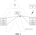
- FIG. 1 a schematic diagram of a system 10, according to one or more embodiments.
- System 10 includes one or more medical devices 12 in electrical communication with one or more power devices 14 such as via one or more wired connection, for example.
- System 10 includes one or more external devices 16 in electrical communication with the power device 14 such as using wireless signals and/or wireless communication.
- System 10 may optionally include a host device 18 in communication with external device 16.
- Medical device 12 may correspond to any medical device that is implantable within a patient 20 and that may use power received from an external power source to perform at least one function.
- medical device 12 may be a left ventricular assist device (LVAD), other assist devices, devices with rechargeable batteries, among other devices known in the art.
- Power device 14 includes one or more coils for receiving wireless power signals where the power signals may be electrically converted to power that is usable by medical device 12 as is known in the art.
- Power device 14 includes monitoring unit 24 that is configured to perform one or more power device 14 functions as described herein such as with respect to detecting a reduction in performance in receiving wireless power signals as described herein.
- External device 16 includes coils 21 for providing wireless power signals to power device 14 as is known in the art.
- external device 16 includes analysis unit 25 that is configured to perform one or more determinations based at least in part on information/data received from power device 14 and/or medical device 12, and other data that that may be determined by external device 16, as described herein.
- external device 16 may be in data communication with one or more of power device 14, medical device 12, host device 18, etc., via one or more wireless communication protocols.
- the wireless power signals communicated between coils 22 and 24 may transfer data between power device 14 and external device 16.
- the wireless power signals may be used solely for providing power such that these signals do not carry data.
- External device 16 and/or power device 14 and/or medical device 12 may be in data communication with host device 18 where host device 18 may be configured to display one or more notifications, communicate with other devices with one or more networks, etc.
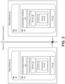
- An example implementation, in accordance with one or more embodiments, of medical device 12, power device 14 and external device 16 discussed in the preceding paragraphs will now be described with reference to FIG. 2 .
- System 10 includes power device 14 that includes hardware 26.
- the hardware 26 may include a communication interface 28 for setting up and maintaining a wired or wireless connection with an interface of a different communication device of the system 10 such as with one or more of medical device 12, external device 16 and host device 18.
- the hardware 26 of the power device 14 further includes processing circuitry 30.
- the processing circuitry 30 may include a processor 32 and a memory 34.
- the processing circuitry 30 may comprise integrated circuitry for processing and/or control, e.g., one or more processors and/or processor cores and/or FPGAs (Field Programmable Gate Array) and/or ASICs (Application Specific Integrated Circuitry) adapted to execute instructions.
- the processor 32 may be configured to access (e.g., write to and/or read from) the memory 34, which may comprise any kind of volatile and/or nonvolatile memory, e.g., cache and/or buffer memory and/or RAM (Random Access Memory) and/or ROM (Read-Only Memory) and/or optical memory and/or EPROM (Erasable Programmable Read-Only Memory).
- the memory 34 may comprise any kind of volatile and/or nonvolatile memory, e.g., cache and/or buffer memory and/or RAM (Random Access Memory) and/or ROM (Read-Only Memory) and/or optical memory and/or EPROM (Erasable Programmable Read-Only Memory).
- the power device further has software 36 stored internally in, for example, memory 34, or stored in external memory (e.g., database, storage array, network storage device, etc.) accessible by the power device 14 via an external connection.
- the software 36 may be executable by the processing circuitry 30.
- the processing circuitry 30 may be configured to control any of the methods and/or processes described herein and/or to cause such methods, and/or processes to be performed, e.g., by power device 14.
- Processor 32 corresponds to one or more processors 32 for performing power device 14 functions described herein.
- the memory 34 is configured to store data, programmatic software code and/or other information described herein.
- the software 36 may include instructions that, when executed by the processor 32 and/or processing circuitry 30, causes the processor 32 and/or processing circuitry 30 to perform the processes described herein with respect to power device 14.
- processing circuitry 30 of the power device 14 may include monitoring unit 24 configured to perform one or more power device 14 functions as described herein such as with respect to TETS for wireless transfer of power from an external energy transfer coil to an implantable energy transfer coil, as described herein.
- System 10 also includes external device 16 that may be configured to be positioned external of patient 20.
- External device 16 includes hardware 38.
- the hardware 38 may include a communication interface 40 for setting up and maintaining a wired or wireless connection with an interface of a different communication device of the system 10 such as with one or more of medical device 12, power device 14 and host device 18.
- communication interface 40 may receive one or more of an indication of at least one determined measurable electrical characteristic, and indication of power received by the power device 14, among other data and/or indications.
- the hardware 38 of the external device 16 further includes processing circuitry 42.
- the processing circuitry 42 may include a processor 44 and a memory 46.
- the processing circuitry 42 may comprise integrated circuitry for processing and/or control, e.g., one or more processors and/or processor cores and/or FPGAs (Field Programmable Gate Array) and/or ASICs (Application Specific Integrated Circuitry) adapted to execute instructions.
- the processor 44 may be configured to access (e.g., write to and/or read from) the memory 46, which may comprise any kind of volatile and/or nonvolatile memory, e.g., cache and/or buffer memory and/or RAM (Random Access Memory) and/or ROM (Read-Only Memory) and/or optical memory and/or EPROM (Erasable Programmable Read-Only Memory).
- the memory 46 may comprise any kind of volatile and/or nonvolatile memory, e.g., cache and/or buffer memory and/or RAM (Random Access Memory) and/or ROM (Read-Only Memory) and/or optical memory and/or EPROM (Erasable Programmable Read-Only Memory).
- the external device 16 further has software 48 stored internally in, for example, memory 46, or stored in external memory (e.g., database, storage array, network storage device, etc.) accessible by the external device 16 via an external connection.
- the software 48 may be executable by the processing circuitry 42.
- the processing circuitry 42 may be configured to control any of the methods and/or processes described herein and/or to cause such methods, and/or processes to be performed, e.g., by external device 16.
- Processor 44 corresponds to one or more processors 44 for performing external device 16 functions described herein.
- the memory 46 is configured to store data, programmatic software code and/or other information described herein.
- the software 48 may include instructions that, when executed by the processor 44 and/or processing circuitry 42, causes the processor 44 and/or processing circuitry 42 to perform the processes described herein with respect to power device 14.
- processing circuitry 42 of the external device 16 may include analysis unit 25 configured to perform one or more external device 16 function such as with respect to analysis of measurement data and/or other data, as described herein.
- external device 16 may determine one or more of a wireless power transfer efficiency, long term moving average of at least one measurable electrical characteristic, among other determinations, as described herein.
- analysis unit 25 may be configured to perform similar functions of monitoring unit 24 but with respect to external device 16.
- analysis unit 25 may perform Blocks S100 and S102, described below, but with respect to a plurality of pathways in the external device 16.
- FIG. 3 is a flowchart illustrating an exemplary process of power device 14 according to some embodiments of the present disclosure.
- One or more Blocks and/or functions performed by power device 14 may be performed by one or more elements of power device 14 such as by monitoring unit 24 in processing circuitry 30, processor 32, etc.
- power device 14 such as via one or more of processing circuitry 30, processor 32, monitoring unit 24, communication interface 28, etc. is configured to determine (Block S 100) at least one measurable electrical characteristic in a plurality of electrical pathways in the power device 14 including an electrical pathway to the first coil, as described herein.
- power device 14 such as via one or more of processing circuitry 30, processor 32, monitoring unit 24, communication interface 28, etc. is configured to detect (Block S102) reduced performance in receiving wireless power signals based at least in part on the determined at least one measurable electrical characteristic, as described herein.
- processing circuitry 30 may detect reduced performance in using the wireless power signals and/or reduced performance in another measurable performance characteristic related to communicating wireless power signals and/or using the wireless power signals to power the medical device 12.
- the plurality of electrical pathways includes a feedthrough cables, connectors and coil windings.
- the processing circuitry 30 is further configured to trigger a notification if any one of the at least one measurable electrical characteristic is one of below and above a predefined threshold, or meets a predefined criterion.
- the power device 14 is positioned one of proximate and within the medical device 12.
- the detection of reduced performance may be based at least on one of periodic/aperiodic monitoring and/or determining of at least one measurable electrical characteristic such as impedance/continuity checks of connections (i.e., at least one impedance value), etc.
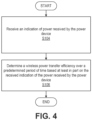
- FIG. 4 is a flowchart illustrating an exemplary process of external device 16 according to some embodiments of the present disclosure.
- One or more Blocks and/or functions performed by external device 16 may be performed by one or more elements of external device 16 such as by analysis unit 25 in processing circuitry 42, processor 44, etc.
- external device 16 such as via one or more of processing circuitry 42, processor 44, analysis unit 25, communication interface 40, etc. is configured to receive (Block S104) an indication of power received by the power device 14, as described herein.
- external device 16 such as via one or more of processing circuitry 42, processor 44, analysis unit 25, communication interface 40, etc. is configured to determine (Block S106) a wireless power transfer efficiency over a predetermined period of time based at least in part on the received indication of the power received by the power device 14, as described herein.
- the wireless power transfer efficiency over the predetermined period of time corresponds to a long term moving average.
- the long term moving average indicates whether performance is degrading due to at least one non-alignment factor between the first coil 22 and second coil 21.
- the at least one non-alignment factor includes at least one of increased fat thickness of a person in which the implantable power device 14 is implanted and degradation of at least one material characteristic of the implantable power device 14. For example, increased fat thickness of a person may be caused by an increase in fatty tissue or subcutaneous fluid accumulation where the increased fat thickness may result in increased distance between the implanted coil and the skin surface.
- the at least one non-alignment factor includes at least one characteristic of a person that causes the distance between the implanted coil and the skin surface (or external coil) to increase.
- the processing circuitry 30 is further configured to trigger a notification indicating if the long term moving average meets a predefined threshold.
- the processing circuitry 42 is further configured to receive an indication of the determined at least one measurable electrical characteristic, and determine a long term moving average based at least in part on the determined at least one measurable electrical characteristic. According to one or more embodiments, the processing circuitry 42 is further configured to determine one or more of a quality factor (Q) assessment, power transmitted assessment of power transfer efficiency versus measured temperature, long term efficiency trending (i.e., wireless power transfer efficiency) based at least in part on data and/or indications received from power device 14 and/or medical device 12.
- Q quality factor
- the external device 16 may determine at least one measurable electrical characteristic associated with the external device 16.
- the at least one measurable electrical characteristic may include at least one characteristic of one or more of coil 21, cable(s) of external device 16, interconnects of external device 16, etc.
- the at least one measurable electrical characteristic is determined/measured by the external device 16 during one or more predefined/predetermined time periods.
- one or more measurable electrical characteristics may be measured when there is no wireless power transfer between the power device 14 and external device 16 and/or during times when there is no wireless power being transmitted from the external device 16.
- the external device 16 may target specific predefined times to perform the measurements and/or may perform periodic measurements when wireless power transfer is not occurring. The measurements may be processed by external device 16 to determine whether to keep the measurements.
- the external device 16 may determine that there is no a metal object proximate the external device 16 by at least in part perform and storing measurements when the coil 21 is moving (e.g., the external device 16 may move such as based on sensor data associated with the external device 16 such accelerometer data), which may imply that the external device 16 is not positioned on an object that may be metal.
- a long term average of the efficiency may be used to indicate and/or detect degrading performance.
- the long term efficiency is determined by external device 16 based at least in part on received data and/or indications from, for example, power device 14. Degrading performance could be a result of increasing fat thickness of patient 20 between internal/implanted coils 22 and external coils 21 or due to gradual worsening of material characteristics such as conductivity.
- an automatic indication of degraded performance may be presented to the patient or clinician (via a wireless link and/or host device 18).
- the long term trend of efficiency over time could be presented in a periodic programmer or CareLink report to allow the clinician (or MDT) to make more subjective assessments of degrading performance.
- Power device 14 may periodically measure at least one measurable electrical characteristic such as the impedance and continuity of one or more electrical pathways that traverse through one or more of feedthroughs, connectors, header on power device 14 through connector, cable, coil windings of coils 22. These measurements may be used to detect both sudden loss of continuity below and/or above some threshold value, or the gradual worsening of measured electrical characteristic(s).
- the sudden loss of continuity may correspond to an increase in impedance by at least a predefined amount and/or impedance exceeding a predefined threshold.
- external device 16 such as via analysis unit 25 may be configured to periodically measure at least one measurable electrical characteristic such as the impedance and continuity of one or more electrical pathways that traverse through one or more of feedthroughs, connectors, header on external device 16 through connector, cable, coil windings of coils 21. These measurements may be used to detect both sudden loss of continuity below and/or above some threshold value, or the gradual worsening of measured electrical characteristic(s).
- the sudden loss of continuity may correspond to an increase in impedance by at least a predefined amount and/or impedance exceeding a predefined threshold.
- Q may be measured when not charging by stopping the driving of the coil and measuring ringdown, for example.
- Q that does not follow a normal distribution with finite range may be used to detect failure modes for power device 14 and/or external device 16.
- Q may be modeled for comparison to measured Q and/or for detecting a failure.
- Q may be determined by power device 14 with respect to coil 21 as described above.
- Power transmitter i.e., power device 14 assessment of power transfer efficiency versus measured temperature
- the external system e.g., external device 16, host device 18, etc.
- the external system could be used to evaluate performance degradation by monitoring efficiency and component temperature levels. For example, if the efficiency monitored by external device 16 is getting worse but the temperature level(s) of one or more components at power device 14 and/or external device 16 remain the same or within a predefined temperature range, then processing circuitry 42 may determine that the reduced efficiency is not caused by the one or more components of power device 14 or external device 16 and/or is caused by misalignment of the power device 14 with the external device 16.
- processing circuitry 42 may determine that the reduced efficiency is caused by the one or more components of power device 14 and/or one or more components of external device 16.
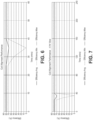
- FIGs. 6-9 are diagrams of coil alignment performance over various time periods in accordance with one or more embodiments of the invention.
- the long term alignment tracking provided by monitoring unit 24 and/or analysis unit 25 logs data related to TETS coil alignment.
- an indicator of historical maximum achieved efficiency may be used to allow a longer term comparison of the current and historical efficiency. For example, data logging related to TETS coil alignment performance may occur every 5 minutes where the following data points are logged:
- the long term alignment trend information may be communicated to host device 18 and/or other device for display to a user.
- the display may allow for selection of views of various time periods such as 1 hours, 4 hours, 1 day, 3 days, 7 days, 14 days, 30 days similar to other 5-minute log data such as power, speed flow, pulsitility of a device such as medical device 12. If a remote monitoring transmission to CareLink has occurred, the trend is visible on the CareLink Quicklook screen as a view of the last 14 days; however, no data points may be logged while in Free mode (i.e., from the initial press of "intent to enter Free mode" until TETS power is reestablished for more than 1 minute, for example).
- free mode may correspond to a time period where the power device 14 is utilizing implanted battery power rather than TETS power from the external device 16.
- the log data may be stored temporarily a power device 14 such as via memory 34 until the next connection (e.g., BLUETOOTH connection) with external device 16 (e.g., iController), during which the log data is transmitted to external device 16 for long term storage.
- next connection e.g., BLUETOOTH connection
- external device 16 e.g., iController
- an implanted LVAD system may provide significant hazard mitigation supporting the safety/efficacy profile of the system, increase patient/clinician confidence in the system 10, among other advantages.
- the described techniques may be implemented in hardware, software, firmware, or any combination thereof. If implemented in software, the functions may be stored as one or more instructions or code on a computer-readable medium and executed by a hardware-based processing unit.
- Firmware may correspond to software that is stored in read-only memory.
- Computer-readable media may include non-transitory computer-readable media, which corresponds to a tangible medium such as data storage media (e.g., RAM, ROM, EEPROM, flash memory, or any other medium that can be used to store desired program code in the form of instructions or data structures and that can be accessed by a computer).
- processors such as one or more digital signal processors (DSPs), general purpose microprocessors, application specific integrated circuits (ASICs), field programmable logic arrays (FPGAs), or other equivalent integrated or discrete logic circuitry.
- DSPs digital signal processors
- ASICs application specific integrated circuits
- FPGAs field programmable logic arrays
- processors may refer to any of the foregoing structure or any other physical structure suitable for implementation of the described techniques. Also, the techniques could be fully implemented in one or more circuits or logic elements.
Landscapes
- Engineering & Computer Science (AREA)
- Health & Medical Sciences (AREA)
- Heart & Thoracic Surgery (AREA)
- Computer Networks & Wireless Communication (AREA)
- Power Engineering (AREA)
- Veterinary Medicine (AREA)
- Biomedical Technology (AREA)
- Cardiology (AREA)
- Life Sciences & Earth Sciences (AREA)
- Animal Behavior & Ethology (AREA)
- General Health & Medical Sciences (AREA)
- Public Health (AREA)
- Anesthesiology (AREA)
- Mechanical Engineering (AREA)
- Hematology (AREA)
- Nuclear Medicine, Radiotherapy & Molecular Imaging (AREA)
- Radiology & Medical Imaging (AREA)
- Electrotherapy Devices (AREA)
- Measuring And Recording Apparatus For Diagnosis (AREA)
Claims (10)
- System (10), umfassend:
eine Stromvorrichtung (14), die in einen Patienten (20) implantierbar ist, zum Versorgen einer implantierbaren medizinischen Vorrichtung (12) mit Strom, wobei die Stromvorrichtung einschließt:eine erste Spule (22), die konfiguriert ist, um Drahtlosstromsignale zum Versorgen der implantierbaren medizinischen Vorrichtung (12) mit Strom zu empfangen;eine Verarbeitungsschaltlogik (30), die konfiguriert ist zum:Bestimmen von mindestens einer messbaren elektrischen Eigenschaft in einer Vielzahl von elektrischen Pfaden in der Stromvorrichtung (14), einschließlich eines elektrischen Pfads zu der ersten Spule (22); undErkennen einer verringerten Leistung beim Empfangen von Drahtlosstromsignalen, mindestens teilweise basierend auf der bestimmten mindestens einen messbaren elektrischen Eigenschaft. - System nach Anspruch 1, ferner umfassend eine externe Vorrichtung (16), die konfiguriert ist, um außerhalb des Patienten positioniert zu werden, zum Bereitstellen von Strom an die implantierbare medizinische Vorrichtung (12), wobei die externe Vorrichtung (16) einschließt:eine zweite Spule (21) zum Übermitteln von Stromsignalen;die Verarbeitungsschaltlogik (42), die konfiguriert ist zum:Empfangen einer Anzeige von Strom, die durch die Stromvorrichtung (14) empfangen wird; undBestimmen einer Effizienz einer Drahtlosstromübertragung über einen zuvor bestimmten Zeitraum basierend mindestens teilweise auf der empfangenen Anzeige des Stroms, der durch die Stromvorrichtung (14) empfangen wird.
- System nach Anspruch 2, wobei die Effizienz der Drahtlosstromübertragung über den zuvor bestimmten Zeitraum einem gleitenden Langzeitdurchschnitt entspricht.
- System nach Anspruch 3, wobei der gleitende Langzeitdurchschnitt anzeigt, ob sich die Leistung aufgrund von mindestens einem Nichtausrichtungsfaktor zwischen der ersten Spule (22) und der zweiten Spule (21) verschlechtert.
- System nach Anspruch 4, wobei der mindestens eine Nichtausrichtungsfaktor mindestens eines einschließt von einer erhöhten Fettdicke einer Person, in die die Stromvorrichtung (14) implantiert ist, und einer Verschlechterung mindestens einer Materialeigenschaft der Stromvorrichtung (14).
- System nach Anspruch 3, wobei die Verarbeitungsschaltlogik ferner konfiguriert ist, um eine Benachrichtigung auszulösen, falls der gleitende Langzeitdurchschnitt einen vordefinierten Schwellenwert erreicht.
- System nach Anspruch 2, wobei die Verarbeitungsschaltlogik ferner konfiguriert ist zum:Empfangen einer Anzeige der bestimmten mindestens einen messbaren elektrischen Eigenschaft; undBestimmen eines gleitenden Langzeitdurchschnitts, mindestens teilweise basierend auf der bestimmten mindestens einen messbaren elektrischen Eigenschaft.
- System nach Anspruch 1, wobei die Vielzahl von elektrischen Pfaden Durchführungskabel, Verbinder und Spulenwicklungen einschließt.
- System nach Anspruch 8, wobei die Verarbeitungsschaltlogik ferner konfiguriert ist, um eine Benachrichtigung auszulösen, falls eine beliebige der mindestens einen messbaren elektrischen Eigenschaften eines von unter oder über einem vordefinierten Schwellenwert liegt.
- System nach Anspruch 1, wobei die Stromvorrichtung (14) eines von in der Nähe und innerhalb der medizinischen Vorrichtung (12) positioniert ist.
Applications Claiming Priority (3)
| Application Number | Priority Date | Filing Date | Title |
|---|---|---|---|
| US202062962334P | 2020-01-17 | 2020-01-17 | |
| US17/111,590 US12015281B2 (en) | 2020-01-17 | 2020-12-04 | Integrity monitoring for a transcutaneous energy system |
| PCT/US2020/065499 WO2021146019A1 (en) | 2020-01-17 | 2020-12-17 | Integrity monitoring for a transcutaneous energy system |
Publications (2)
| Publication Number | Publication Date |
|---|---|
| EP4090418A1 EP4090418A1 (de) | 2022-11-23 |
| EP4090418B1 true EP4090418B1 (de) | 2025-01-29 |
Family
ID=76856557
Family Applications (1)
| Application Number | Title | Priority Date | Filing Date |
|---|---|---|---|
| EP20845251.6A Active EP4090418B1 (de) | 2020-01-17 | 2020-12-17 | Integritätsüberwachung für ein transkutanes energiesystem |
Country Status (3)
| Country | Link |
|---|---|
| US (1) | US12015281B2 (de) |
| EP (1) | EP4090418B1 (de) |
| WO (1) | WO2021146019A1 (de) |
Families Citing this family (2)
| Publication number | Priority date | Publication date | Assignee | Title |
|---|---|---|---|---|
| US11870270B2 (en) * | 2009-07-17 | 2024-01-09 | Peter Forsell | Medical system comprising implants |
| US11883675B2 (en) | 2019-12-20 | 2024-01-30 | Medtronic, Inc. | Transcutaneous energy transfer system including alarm |
Family Cites Families (18)
| Publication number | Priority date | Publication date | Assignee | Title |
|---|---|---|---|---|
| US5350413B1 (en) * | 1990-06-21 | 1999-09-07 | Heart Inst Research Corp | Transcutaneous energy transfer device |
| US5995874A (en) * | 1998-02-09 | 1999-11-30 | Dew Engineering And Development Limited | Transcutaneous energy transfer device |
| US6149683A (en) * | 1998-10-05 | 2000-11-21 | Kriton Medical, Inc. | Power system for an implantable heart pump |
| US6772011B2 (en) | 2002-08-20 | 2004-08-03 | Thoratec Corporation | Transmission of information from an implanted medical device |
| US7225032B2 (en) | 2003-10-02 | 2007-05-29 | Medtronic Inc. | External power source, charger and system for an implantable medical device having thermal characteristics and method therefore |
| US8140168B2 (en) | 2003-10-02 | 2012-03-20 | Medtronic, Inc. | External power source for an implantable medical device having an adjustable carrier frequency and system and method related therefore |
| US9452296B2 (en) * | 2007-10-16 | 2016-09-27 | Peter Forsell | Method and system for controlling supply of energy to an implantable medical device |
| WO2009051538A1 (en) * | 2007-10-16 | 2009-04-23 | Milux Holding Sa | A method and apparatus for supplying energy to a medical device |
| BRPI0819622B8 (pt) * | 2007-11-27 | 2021-06-22 | Implantica Patent Ltd | controle de transferência de energia adaptado para um sistema de dispositivo médico |
| US8700174B2 (en) | 2011-01-28 | 2014-04-15 | Medtronic, Inc. | Recharge coupling efficiency for patient posture state |
| US8974366B1 (en) * | 2012-01-10 | 2015-03-10 | Piezo Energy Technologies, LLC | High power ultrasound wireless transcutaneous energy transfer (US-TET) source |
| US10525181B2 (en) | 2012-07-27 | 2020-01-07 | Tc1 Llc | Resonant power transfer system and method of estimating system state |
| US9209634B2 (en) | 2012-09-07 | 2015-12-08 | Greatbatch Ltd. | Method of improving battery recharge efficiency by statistical analysis |
| US9399142B2 (en) | 2014-01-29 | 2016-07-26 | GiMer Medical Co., Ltd. | Implantable medical device and system |
| EP3161926B8 (de) * | 2014-06-25 | 2020-07-15 | Daxsonics Ultrasound Inc | Ultraschallleistungsverbindungen und verfahren für verbesserte effizienz |
| US9855376B2 (en) | 2014-07-25 | 2018-01-02 | Minnetronix, Inc. | Power scaling |
| JP7233424B2 (ja) | 2017-11-02 | 2023-03-06 | エルジー イノテック カンパニー リミテッド | 無線充電方法およびそのための装置 |
| WO2019183126A1 (en) | 2018-03-20 | 2019-09-26 | Tc1 Llc | Mechanical gauge for estimating inductance changes in resonant power transfer systems with flexible coils for use with implanted medical devices |
-
2020
- 2020-12-04 US US17/111,590 patent/US12015281B2/en active Active
- 2020-12-17 WO PCT/US2020/065499 patent/WO2021146019A1/en not_active Ceased
- 2020-12-17 EP EP20845251.6A patent/EP4090418B1/de active Active
Also Published As
| Publication number | Publication date |
|---|---|
| US12015281B2 (en) | 2024-06-18 |
| WO2021146019A1 (en) | 2021-07-22 |
| US20210220639A1 (en) | 2021-07-22 |
| EP4090418A1 (de) | 2022-11-23 |
Similar Documents
| Publication | Publication Date | Title |
|---|---|---|
| EP4090418B1 (de) | Integritätsüberwachung für ein transkutanes energiesystem | |
| US8306766B2 (en) | Systems and methods for calibrating physiological characteristic sensors | |
| EP1699352B1 (de) | Verfahren und Vorrichtung zur Überprüfung der Integrität von Sensordaten | |
| US8015977B2 (en) | Indicator tool for use with an implantable medical device | |
| KR102535394B1 (ko) | 연속혈당측정시스템에서 혈당값을 교정하는 방법 | |
| JP2010524639A (ja) | 閉ループ/半閉ループ治療修正システム | |
| CA2536133A1 (en) | A method of monitoring glucose level | |
| EP4085824B1 (de) | Verfahren zum senden oder empfangen von biometrischen informationen in einem kontinuierlichen blutzuckermesssystem | |
| KR102475913B1 (ko) | 연속 혈당 측정 시스템에서 교정 정보를 관리하는 방법 | |
| EP4093502B1 (de) | Implantierbare medizinische vorrichtung unter verwendung eines temperatursensors zum bestimmen des infektionsstatus eines patienten | |
| EP4111965B1 (de) | Glukosesensor-identifizierung unter verwendung von elektrischen parametern | |
| EP2429651B1 (de) | Nachweis des ordnungsgemässen einsatzes medizinischer elektroden in eine medizinische vorrichtung | |
| CN119785523A (zh) | 一种基于无线技术的胰岛素泵安全提醒系统 | |
| WO2026067891A1 (en) | Compensation method and device for continuous glucose monitoring apparaus | |
| US20250107732A1 (en) | Correction alarm method | |
| US20250275684A1 (en) | Method and system for intra-abdominal pressure evaluation and warning | |
| CN121881658A (zh) | 一种基于等效集总元件模型的有源植入式医疗器械体内射频响应建模方法 | |
| WO2021239527A1 (en) | Implantable medical device with temperature sensor | |
| CA3231415A1 (en) | Calibration alarm method |
Legal Events
| Date | Code | Title | Description |
|---|---|---|---|
| STAA | Information on the status of an ep patent application or granted ep patent |
Free format text: STATUS: UNKNOWN |
|
| STAA | Information on the status of an ep patent application or granted ep patent |
Free format text: STATUS: THE INTERNATIONAL PUBLICATION HAS BEEN MADE |
|
| PUAI | Public reference made under article 153(3) epc to a published international application that has entered the european phase |
Free format text: ORIGINAL CODE: 0009012 |
|
| STAA | Information on the status of an ep patent application or granted ep patent |
Free format text: STATUS: REQUEST FOR EXAMINATION WAS MADE |
|
| 17P | Request for examination filed |
Effective date: 20220812 |
|
| AK | Designated contracting states |
Kind code of ref document: A1 Designated state(s): AL AT BE BG CH CY CZ DE DK EE ES FI FR GB GR HR HU IE IS IT LI LT LU LV MC MK MT NL NO PL PT RO RS SE SI SK SM TR |
|
| DAV | Request for validation of the european patent (deleted) | ||
| DAX | Request for extension of the european patent (deleted) | ||
| GRAP | Despatch of communication of intention to grant a patent |
Free format text: ORIGINAL CODE: EPIDOSNIGR1 |
|
| STAA | Information on the status of an ep patent application or granted ep patent |
Free format text: STATUS: GRANT OF PATENT IS INTENDED |
|
| RIC1 | Information provided on ipc code assigned before grant |
Ipc: H02J 50/90 20160101ALI20240219BHEP Ipc: H02J 50/10 20160101ALI20240219BHEP Ipc: A61M 60/875 20210101ALI20240219BHEP Ipc: A61M 60/216 20210101ALI20240219BHEP Ipc: A61M 60/178 20210101ALI20240219BHEP Ipc: A61B 5/00 20060101ALI20240219BHEP Ipc: H02J 7/00 20060101ALI20240219BHEP Ipc: H02J 50/80 20160101ALI20240219BHEP Ipc: A61N 1/378 20060101AFI20240219BHEP |
|
| INTG | Intention to grant announced |
Effective date: 20240307 |
|
| GRAJ | Information related to disapproval of communication of intention to grant by the applicant or resumption of examination proceedings by the epo deleted |
Free format text: ORIGINAL CODE: EPIDOSDIGR1 |
|
| STAA | Information on the status of an ep patent application or granted ep patent |
Free format text: STATUS: REQUEST FOR EXAMINATION WAS MADE |
|
| INTC | Intention to grant announced (deleted) | ||
| GRAP | Despatch of communication of intention to grant a patent |
Free format text: ORIGINAL CODE: EPIDOSNIGR1 |
|
| STAA | Information on the status of an ep patent application or granted ep patent |
Free format text: STATUS: GRANT OF PATENT IS INTENDED |
|
| INTG | Intention to grant announced |
Effective date: 20240816 |
|
| GRAS | Grant fee paid |
Free format text: ORIGINAL CODE: EPIDOSNIGR3 |
|
| GRAA | (expected) grant |
Free format text: ORIGINAL CODE: 0009210 |
|
| STAA | Information on the status of an ep patent application or granted ep patent |
Free format text: STATUS: THE PATENT HAS BEEN GRANTED |
|
| AK | Designated contracting states |
Kind code of ref document: B1 Designated state(s): AL AT BE BG CH CY CZ DE DK EE ES FI FR GB GR HR HU IE IS IT LI LT LU LV MC MK MT NL NO PL PT RO RS SE SI SK SM TR |
|
| REG | Reference to a national code |
Ref country code: GB Ref legal event code: FG4D |
|
| REG | Reference to a national code |
Ref country code: CH Ref legal event code: EP |
|
| REG | Reference to a national code |
Ref country code: DE Ref legal event code: R096 Ref document number: 602020045610 Country of ref document: DE |
|
| REG | Reference to a national code |
Ref country code: IE Ref legal event code: FG4D |
|
| REG | Reference to a national code |
Ref country code: NL Ref legal event code: MP Effective date: 20250129 |
|
| PG25 | Lapsed in a contracting state [announced via postgrant information from national office to epo] |
Ref country code: NL Free format text: LAPSE BECAUSE OF FAILURE TO SUBMIT A TRANSLATION OF THE DESCRIPTION OR TO PAY THE FEE WITHIN THE PRESCRIBED TIME-LIMIT Effective date: 20250129 |
|
| PG25 | Lapsed in a contracting state [announced via postgrant information from national office to epo] |
Ref country code: RS Free format text: LAPSE BECAUSE OF FAILURE TO SUBMIT A TRANSLATION OF THE DESCRIPTION OR TO PAY THE FEE WITHIN THE PRESCRIBED TIME-LIMIT Effective date: 20250429 |
|
| PG25 | Lapsed in a contracting state [announced via postgrant information from national office to epo] |
Ref country code: FI Free format text: LAPSE BECAUSE OF FAILURE TO SUBMIT A TRANSLATION OF THE DESCRIPTION OR TO PAY THE FEE WITHIN THE PRESCRIBED TIME-LIMIT Effective date: 20250129 |
|
| PG25 | Lapsed in a contracting state [announced via postgrant information from national office to epo] |
Ref country code: PL Free format text: LAPSE BECAUSE OF FAILURE TO SUBMIT A TRANSLATION OF THE DESCRIPTION OR TO PAY THE FEE WITHIN THE PRESCRIBED TIME-LIMIT Effective date: 20250129 |
|
| PG25 | Lapsed in a contracting state [announced via postgrant information from national office to epo] |
Ref country code: ES Free format text: LAPSE BECAUSE OF FAILURE TO SUBMIT A TRANSLATION OF THE DESCRIPTION OR TO PAY THE FEE WITHIN THE PRESCRIBED TIME-LIMIT Effective date: 20250129 |
|
| REG | Reference to a national code |
Ref country code: LT Ref legal event code: MG9D |
|
| PG25 | Lapsed in a contracting state [announced via postgrant information from national office to epo] |
Ref country code: IS Free format text: LAPSE BECAUSE OF FAILURE TO SUBMIT A TRANSLATION OF THE DESCRIPTION OR TO PAY THE FEE WITHIN THE PRESCRIBED TIME-LIMIT Effective date: 20250529 Ref country code: NO Free format text: LAPSE BECAUSE OF FAILURE TO SUBMIT A TRANSLATION OF THE DESCRIPTION OR TO PAY THE FEE WITHIN THE PRESCRIBED TIME-LIMIT Effective date: 20250429 |
|
| REG | Reference to a national code |
Ref country code: AT Ref legal event code: MK05 Ref document number: 1762862 Country of ref document: AT Kind code of ref document: T Effective date: 20250129 |
|
| PG25 | Lapsed in a contracting state [announced via postgrant information from national office to epo] |
Ref country code: HR Free format text: LAPSE BECAUSE OF FAILURE TO SUBMIT A TRANSLATION OF THE DESCRIPTION OR TO PAY THE FEE WITHIN THE PRESCRIBED TIME-LIMIT Effective date: 20250129 |
|
| PG25 | Lapsed in a contracting state [announced via postgrant information from national office to epo] |
Ref country code: LV Free format text: LAPSE BECAUSE OF FAILURE TO SUBMIT A TRANSLATION OF THE DESCRIPTION OR TO PAY THE FEE WITHIN THE PRESCRIBED TIME-LIMIT Effective date: 20250129 Ref country code: PT Free format text: LAPSE BECAUSE OF FAILURE TO SUBMIT A TRANSLATION OF THE DESCRIPTION OR TO PAY THE FEE WITHIN THE PRESCRIBED TIME-LIMIT Effective date: 20250529 |
|
| PG25 | Lapsed in a contracting state [announced via postgrant information from national office to epo] |
Ref country code: GR Free format text: LAPSE BECAUSE OF FAILURE TO SUBMIT A TRANSLATION OF THE DESCRIPTION OR TO PAY THE FEE WITHIN THE PRESCRIBED TIME-LIMIT Effective date: 20250430 Ref country code: BG Free format text: LAPSE BECAUSE OF FAILURE TO SUBMIT A TRANSLATION OF THE DESCRIPTION OR TO PAY THE FEE WITHIN THE PRESCRIBED TIME-LIMIT Effective date: 20250129 |
|
| PG25 | Lapsed in a contracting state [announced via postgrant information from national office to epo] |
Ref country code: AT Free format text: LAPSE BECAUSE OF FAILURE TO SUBMIT A TRANSLATION OF THE DESCRIPTION OR TO PAY THE FEE WITHIN THE PRESCRIBED TIME-LIMIT Effective date: 20250129 |
|
| PG25 | Lapsed in a contracting state [announced via postgrant information from national office to epo] |
Ref country code: SE Free format text: LAPSE BECAUSE OF FAILURE TO SUBMIT A TRANSLATION OF THE DESCRIPTION OR TO PAY THE FEE WITHIN THE PRESCRIBED TIME-LIMIT Effective date: 20250129 |
|
| PG25 | Lapsed in a contracting state [announced via postgrant information from national office to epo] |
Ref country code: SM Free format text: LAPSE BECAUSE OF FAILURE TO SUBMIT A TRANSLATION OF THE DESCRIPTION OR TO PAY THE FEE WITHIN THE PRESCRIBED TIME-LIMIT Effective date: 20250129 |
|
| PG25 | Lapsed in a contracting state [announced via postgrant information from national office to epo] |
Ref country code: DK Free format text: LAPSE BECAUSE OF FAILURE TO SUBMIT A TRANSLATION OF THE DESCRIPTION OR TO PAY THE FEE WITHIN THE PRESCRIBED TIME-LIMIT Effective date: 20250129 |
|
| PG25 | Lapsed in a contracting state [announced via postgrant information from national office to epo] |
Ref country code: IT Free format text: LAPSE BECAUSE OF FAILURE TO SUBMIT A TRANSLATION OF THE DESCRIPTION OR TO PAY THE FEE WITHIN THE PRESCRIBED TIME-LIMIT Effective date: 20250129 |
|
| PG25 | Lapsed in a contracting state [announced via postgrant information from national office to epo] |
Ref country code: CZ Free format text: LAPSE BECAUSE OF FAILURE TO SUBMIT A TRANSLATION OF THE DESCRIPTION OR TO PAY THE FEE WITHIN THE PRESCRIBED TIME-LIMIT Effective date: 20250129 Ref country code: EE Free format text: LAPSE BECAUSE OF FAILURE TO SUBMIT A TRANSLATION OF THE DESCRIPTION OR TO PAY THE FEE WITHIN THE PRESCRIBED TIME-LIMIT Effective date: 20250129 |
|
| PG25 | Lapsed in a contracting state [announced via postgrant information from national office to epo] |
Ref country code: RO Free format text: LAPSE BECAUSE OF FAILURE TO SUBMIT A TRANSLATION OF THE DESCRIPTION OR TO PAY THE FEE WITHIN THE PRESCRIBED TIME-LIMIT Effective date: 20250129 |
|
| PG25 | Lapsed in a contracting state [announced via postgrant information from national office to epo] |
Ref country code: SK Free format text: LAPSE BECAUSE OF FAILURE TO SUBMIT A TRANSLATION OF THE DESCRIPTION OR TO PAY THE FEE WITHIN THE PRESCRIBED TIME-LIMIT Effective date: 20250129 |
|
| REG | Reference to a national code |
Ref country code: DE Ref legal event code: R097 Ref document number: 602020045610 Country of ref document: DE |
|
| PLBE | No opposition filed within time limit |
Free format text: ORIGINAL CODE: 0009261 |
|
| STAA | Information on the status of an ep patent application or granted ep patent |
Free format text: STATUS: NO OPPOSITION FILED WITHIN TIME LIMIT |
|
| 26N | No opposition filed |
Effective date: 20251030 |
|
| PGFP | Annual fee paid to national office [announced via postgrant information from national office to epo] |
Ref country code: DE Payment date: 20251126 Year of fee payment: 6 |