EP4090149B1 - Verteilmaschine - Google Patents
Verteilmaschine Download PDFInfo
- Publication number
- EP4090149B1 EP4090149B1 EP21717011.7A EP21717011A EP4090149B1 EP 4090149 B1 EP4090149 B1 EP 4090149B1 EP 21717011 A EP21717011 A EP 21717011A EP 4090149 B1 EP4090149 B1 EP 4090149B1
- Authority
- EP
- European Patent Office
- Prior art keywords
- seed
- separating
- fertilizer
- hopper
- air flow
- Prior art date
- Legal status (The legal status is an assumption and is not a legal conclusion. Google has not performed a legal analysis and makes no representation as to the accuracy of the status listed.)
- Active
Links
Images

Classifications
-
- A—HUMAN NECESSITIES
- A01—AGRICULTURE; FORESTRY; ANIMAL HUSBANDRY; HUNTING; TRAPPING; FISHING
- A01C—PLANTING; SOWING; FERTILISING
- A01C7/00—Sowing
- A01C7/08—Broadcast seeders; Seeders depositing seeds in rows
- A01C7/081—Seeders depositing seeds in rows using pneumatic means
-
- A—HUMAN NECESSITIES
- A01—AGRICULTURE; FORESTRY; ANIMAL HUSBANDRY; HUNTING; TRAPPING; FISHING
- A01C—PLANTING; SOWING; FERTILISING
- A01C19/00—Arrangements for driving working parts of fertilisers or seeders
-
- A—HUMAN NECESSITIES
- A01—AGRICULTURE; FORESTRY; ANIMAL HUSBANDRY; HUNTING; TRAPPING; FISHING
- A01C—PLANTING; SOWING; FERTILISING
- A01C7/00—Sowing
- A01C7/04—Single-grain seeders with or without suction devices
- A01C7/042—Single-grain seeders with or without suction devices using pneumatic means
-
- A—HUMAN NECESSITIES
- A01—AGRICULTURE; FORESTRY; ANIMAL HUSBANDRY; HUNTING; TRAPPING; FISHING
- A01C—PLANTING; SOWING; FERTILISING
- A01C7/00—Sowing
- A01C7/06—Seeders combined with fertilising apparatus
-
- A—HUMAN NECESSITIES
- A01—AGRICULTURE; FORESTRY; ANIMAL HUSBANDRY; HUNTING; TRAPPING; FISHING
- A01C—PLANTING; SOWING; FERTILISING
- A01C7/00—Sowing
- A01C7/20—Parts of seeders for conducting and depositing seed
- A01C7/206—Seed pipes
-
- Y—GENERAL TAGGING OF NEW TECHNOLOGICAL DEVELOPMENTS; GENERAL TAGGING OF CROSS-SECTIONAL TECHNOLOGIES SPANNING OVER SEVERAL SECTIONS OF THE IPC; TECHNICAL SUBJECTS COVERED BY FORMER USPC CROSS-REFERENCE ART COLLECTIONS [XRACs] AND DIGESTS
- Y02—TECHNOLOGIES OR APPLICATIONS FOR MITIGATION OR ADAPTATION AGAINST CLIMATE CHANGE
- Y02P—CLIMATE CHANGE MITIGATION TECHNOLOGIES IN THE PRODUCTION OR PROCESSING OF GOODS
- Y02P60/00—Technologies relating to agriculture, livestock or agroalimentary industries
- Y02P60/14—Measures for saving energy, e.g. in green houses
Definitions
- the invention relates to a distribution machine with at least one seed hopper, at least one fertilizer hopper and a plurality of distribution units, each of the distribution units having at least one pneumatically operated separating device, to which a separating air stream can be supplied or discharged, and a fertilizer application device, the distribution machine being used to provide seed the seed hopper to the distribution units has a seed feeding device operated by conveying air and an energy-operated fertilizer feed device for providing fertilizer to the fertilizer application devices.
- Such distribution machines designed in particular as precision seed drills, are well known and regularly have various components or consumers that require the provision of energy in the form of compressed air or hydraulic pressure medium.
- Components or consumers to be named as examples are separating devices, which require a separating air stream to separate seed, seed tracking devices, which supply the separating devices from a central seed hopper via a conveying air stream with seed for singling, and fertilizer supply devices, which either use granular fertilizer via conveying air or liquid fertilizer convey a pump.
- the pneumatically operated separating devices to which the separating air flow can be supplied or derived, work in a manner known per se:
- a separating device operated via overpressure the separating air flow is subjected to overpressure by a blower, so that the seed is isolated in a manner on a separating element encapsulated in the separating device is pressed and can thus be separated;
- the separating air flow is subjected to negative pressure by a blower, so that it is sucked out of the separating device and can also be used for separating if the separating element is suitably arranged.
- a seed tracker is used regularly when on Distribution units of the distribution machine no or only little voluminous seed hoppers are arranged:
- the seed tracking device conveys seed from the central, voluminous seed hopper via pipelines by means of the conveying air flow to be generated by a blower to the individual separating devices, so that the conveying air flow is divided into the number of separating devices individual conveying flows .
- Generic distribution machines also regularly have a fertilizer supply device in order to distribute fertilizer in addition to the seed: the Fertilizer supply device is set up by means of a blower or a pump to promote granular or liquid fertilizer via a corresponding line system to fertilizer application devices of the distribution units.
- a seed and planting system with a dosing and distribution system is known.
- a distribution device for agricultural application material is known.
- an agricultural implement with a device for feeding granular material is known.
- an agricultural device with metering devices comprising three compressed air supply lines is known.
- From the pamphlet DE 10 2016 204 433 A1 a row unit of an agricultural machine is known.
- the task on which the task is based is therefore to further develop a distribution machine with several consumers and to avoid the known disadvantages.
- energy efficiency is to be increased and the controllability of the energy provided to consumers is to be improved.
- the distributing machine has separate fans in each case for providing the separating air streams to the separating devices, the conveying air to the seed tracking device, and the energy to the fertilizer feeding device.
- the controllability of the energy provided is improved since the separate blowers can preferably be operated independently of one another at different power levels.
- the functions of separating devices, seed tracking and fertilizer supply are also less dependent, which means that an improved work result can be achieved.
- the distribution machine has separate blowers for providing the separating air streams to the separating devices, the conveying air to the seed tracking device, and the energy to the fertilizer feed device. Since a separate energy supplier is assigned to each of the consumers, ie the separating devices, the seed tracking device and the fertilizer delivery device, the energy suppliers, ie blowers, can be operated with a suitable power output.
- the distribution machine thus has a particularly high level of energy efficiency.
- each supplier can be provided with the power required for its, in particular current, operating behavior, so that there are no longer any interfunctional dependencies and the work result is improved in an expedient manner.
- the separate blowers can be controlled independently of one another, preferably via their speed.
- the distribution machine can have a control device.
- the control device is connected to the fans in a signal-conducting manner and can be part of a display and/or operating device.
- the control device can also be a computer unit that is preferably connected to the display and/or operating device in a signal-conducting manner.
- the separate blowers can be controlled via a throttle.
- a separating air flow and a conveying air flow of the seed tracking device can be brought together in the separating device.
- part of the separating air flow can be provided by the conveying air flow in an advantageous manner.
- the blower for providing the separating air flow can therefore be operated at a lower power.
- the conveying air of the seed tracking device can be discharged by means of a separating device. Since the seed is regularly afflicted with environmentally harmful dressing, which can be released during the conveyance between the seed hopper and the separating device and entrained by the conveying air, the conveying air can preferably be discharged close to the ground as a result of this development.
- the discharge of conveying air contaminated with dressing, in particular close to the ground protects the insects in the vicinity of the distribution machine and is therefore beneficial to the environment.
- a further advantageous development of the distribution machine according to the invention is characterized in that the separating device has a seed delivery channel for the individual delivery of seed, the separated seed being accelerated in the seed delivery channel by the separating air flow and/or at least partially by the conveying air of the seed tracking device.
- a separated seed grain is released into the seed delivery channel.
- the separating device can be designed so that the separating air flow and the conveying air at least partially in the Seed delivery channel is directed so that the isolated seeds therein vs. of delivery in free fall can be accelerated.
- This training shows particular synergy with the provision of the separating air and/or the conveying air via separate energy suppliers, since the total air flow available for accelerating the seed grain can thus be controlled in a particularly simple and expedient manner. Furthermore, a particularly simple adjustment of the acceleration or speed of the seed grain to different seeds and/or driving speeds is achieved in this way.
- the separating device has a seed delivery channel for the individual delivery of seed, with the separated seed, which has in particular been accelerated in the seed delivery channel, being able to be braked by means of a catch roller in the area of delivery from the seed delivery channel, so that the separated seed can be deposited equidistantly.
- the placement quality can be improved by slowing down the separated seed from a high intrinsic speed.
- the separated seed grains are preferably decelerated by the catch roller at least approximately to the driving speed of the distributor machine, so that the seed grain can be deposited without rolling as far as possible.
- the catching roller is arranged in the region of the discharge from the seed delivery channel, the seed grain being run over by the catching roller after exiting the seed delivery channel and thus being braked.
- the seed is also pressed into the ground by the catching roller in the manner of a seed pressure roller, which helps seed emergence.
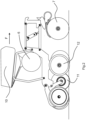
- a distribution machine attached behind a tractor 1 and designed as a precision seed drill 2 is in Fig.1 seen in a perspective view diagonally from behind.
- the precision seed drill 2 At its rear end in the direction of travel F, the precision seed drill 2 has a plurality of distribution units 3 arranged transversely to the direction of travel F and in front of it its own chassis 4 .
- the chassis 4 has two tires arranged next to one another transversely to the direction of travel F and is attached to a frame part of the precision seed drill 2, which extends essentially in the direction of travel F, so that the precision seed drill 2 can be towed like a trailer by means of the agricultural tractor 1 over an agricultural area in the working position shown or can be brought into a transport position over roads and paths.
- the working position of the seed drill 2 shown is characterized in that the distribution units 3, which are attached to an elongated frame part of the seed drill 2, are arranged side by side transversely to the direction of travel F, resulting in a large working width.
- the precision seed drill 2 is thus set up especially for processing large areas, where the seed is deposited in a single manner by means of a pneumatically operated separating device 6 of each distribution unit 3 .
- Each distribution unit 3 also includes a fertilizer application device designed as a disc coulter 7 for the simultaneous application of fertilizer.
- the precision seed drill 2 has a voluminous seed hopper 5.
- the seed tracking device distributes the seed from the seed hopper 5 to the distribution units 3 in an adjustable manner via seed lines (not shown in detail).
- the precision seed drill 2 has a separate energy supplier designed as a seed blower 8a in order to generate the conveying air flow.
- the Saatgutnachschreib beautiful can also include a metering element, which is set up to remove seed in an adjustable amount from the seed hopper 5 and deliver it to the seed lines, not shown, where it is picked up and transported by the conveying air flow.
- the seed tracking device can be designed to be self-regulating, that is to say it can have a fill level element which is set up to automatically interrupt the flow of conveying air when a predetermined fill level is reached.
- the seed lines can have shut-off elements so that it can be set which of the distribution units 3 seed is fed to.
- the seed is fed to the separating devices 6, which are operated with overpressure in this precision seed drill 2.
- the separating devices 6 of each distribution unit 3 can each be supplied with a separating air flow which is under pressure compared to atmospheric pressure and which ensures in a manner known per se that individual seeds adhere to a rotatably drivable separating disk of the separating device 6 and are released again into a seed delivery channel at regular intervals.
- the precision seed drill 2 has a separate energy supplier designed as a separating fan 8c.
- the separating fan 8c is arranged on the frame part of the precision seed drill 2 that is elongated in the direction of travel F and is connected to the separating devices 6 via lines that are not shown in detail.
- the precision seed drill 2 it would be conceivable for the precision seed drill 2 to have a plurality of separating fans 8c and/or for the one or the Separating fan 8c is or are arranged on the frame part which is elongated transversely to the direction of travel F.
- the separating fan 8c can be controlled independently of the seed fan 8a, ie it can also be referred to as a separate energy supplier for providing the separating air streams.
- the precision seed drill 2 has a fertilizer container 9 .
- a fertilizer supply device is provided for providing fertilizer from the fertilizer container 9 to the fertilizer application devices designed as disc coulters 7 .
- the fertilizer supply device distributes the fertilizer from the fertilizer container 9 to the disc coulters 7 in an adjustable manner via fertilizer lines, which are also not shown in detail.
- the fertilizer fan 8b can be controlled independently of the seed fan 8a and the separating fan 8c, ie it can be regarded as a separate energy supplier for providing the energy to the fertilizer supply device.
- the seed fan 8a, the fertilizer fan 8b and the separating fan 8c can each be controlled independently of one another, that is to say they can each be referred to as separate energy suppliers.
- the precision seed drill 2 it would be conceivable to operate at least two consumers, i.e. separating air streams or separating devices 6, seed tracking device and fertilizer supply device, with one energy supplier and to use the third consumer in each case with a separate energy supplier.
- the fertilizer supply device can have a dosing element for removing fertilizer from the fertilizer container 9 in adjustable amounts and delivering it into the fertilizer lines.
- the seed hopper 5 and the fertilizer hopper 9 can be reversed in their arrangement on the seed drill 2, so that the fertilizer hopper 9 is arranged in the direction of travel F in front of the seed hopper.
- the volumes of the seed hopper 5 and the fertilizer hopper 9 can be chosen almost freely.
- the seed fan 8a, the fertilizer fan 8b and the separating fan 8c can be controlled independently of each other via their speed.
- the seed tracking device, the fertilizer supply device and the separating devices 6 can be operated independently of one another or they do not influence each other's functions.
- the seed blower 8a for example, the speed and/or quantity of the seed conveyed from the seed hopper 5 to the distribution units 3 can be adjusted.
- the individual distribution units 3 each have a reservoir serving as a seed buffer 10, in which the seed transported from the central seed hopper 5 to the respective distribution unit 3 by means of the conveying air flow generated by the seed blower 8a collects. From the seed buffer 10, the seed then slips into the separating device 6, such as Fig.2 shows.
- the seed fan 8a it is therefore conceivable for the seed fan 8a to be operated at preferably regular intervals, namely whenever at least one seed buffer 10 is to be supplied with seed.
- the seed blower 8a is operated continuously but, for example, with reduced power, so that a sufficient quantity of seed is always available in each seed buffer 10 for the separating by the separating devices 6 .
- the seed fan 8c can be operated independently of the operating behavior of the fertilizer supply device and the separating devices with the power required for the seed tracking device, so that it works particularly efficiently.
- the distribution units 3 do not have a seed buffer 10 , so that seed transported by the seed tracking device is made available to the separating device 6 almost directly.
- suitable control of the seed blower 8a can ensure that there is always enough seed for singling, because the seed blower 8a can be controlled separately, ie independently of the other energy suppliers 8b, 8c.
- the quantity and/or speed of the fertilizer made available to the disc coulters 7 from the fertilizer container 9 can be adjusted by means of the fertilizer fan 8b.
- the seed fan 8a and the fertilizer fan 8b can be controlled independently of one another in this precision seed drill 2, so that the seed tracking device and the fertilizer supply device can be adjusted and operated independently of one another.
- the separating air flows can be adjusted in terms of volume flow or pressure increase by means of the separating fan 8c, so that, for example, the pressure difference available for separating by means of the separating devices 6 can be varied. Since the separating fan 8c can also be controlled separately, the separating air streams can be adjusted independently of the seed tracking device and the fertilizer feed device.
- a separating air flow and a conveying air flow of the seed tracking device can be brought together in the separating device 6 and the separating air flow and the conveying air flow can thus be adapted to one another or coordinated with one another.
- the conveying air of the seed tracking device can be derived via the separating device 6, in particular in the direction of the tilled soil.
- a separating air stream provided by the separating fan 8c is fed to the separating device 6 via lines (also not shown). After the seed has been separated using a separating disc, for example, it is released into the seed discharge channel.
- the separating air streams and conveying air streams of the seed tracking device brought together in the separating device 6 pass over at least partially out the seed delivery channel and accelerate loose seeds that have been detached therein.
- a furrow in the ground is opened by tillage tools 12, which cover the seed delivery channel, into which the individual grains are shot from the seed delivery channel.
- the seed delivery channel consequently extends from the separating element of the separating device 6 into the area of the tillage tools 12.
- the seed delivery channel is aligned in the delivery area in such a way that the seed can be shot into a gap between the catch roller 11 and the furrow, so that the isolated seed is deposited equidistantly.
- fertilizer can be deposited via the disc coulter 7 from the fertilizer hopper 9 by means of the fertilizer blower 8b.
Landscapes
- Life Sciences & Earth Sciences (AREA)
- Soil Sciences (AREA)
- Environmental Sciences (AREA)
- Sowing (AREA)
- Fertilizing (AREA)
Description
- Die Erfindung betrifft eine Verteilmaschine mit zumindest einem Saatgutbehälter, zumindest einem Düngerbehälter und einer Mehrzahl von Verteilaggregaten, wobei jedes der Verteilaggregate zumindest eine pneumatisch betriebene Vereinzelungseinrichtung, der ein Vereinzelungsluftstrom zuleitbar oder ableitbar ist, und eine Düngerapplikationseinrichtung aufweist, wobei die Verteilmaschine zur Bereitstellung von Saatgut aus dem Saatgutbehälter an die Verteilaggregate eine förderluftbetriebene Saatgutnachführeinrichtung und zur Bereitstellung von Dünger an die Düngerapplikationseinrichtungen eine energiebetriebene Düngerzuführeinrichtung aufweist.
- Derartige, insbesondere als Einzelkornsämaschinen ausgeführt, Verteilmaschinen sind hinlänglich bekannt und weisen regelmäßig verschiedene Komponenten bzw. Verbraucher auf, die der Bereitstellung von Energie in Form von Druckluft oder hydraulischem Druckmittel bedürfen. Beispielhaft zu nennende Komponenten bzw. Verbraucher sind Vereinzelungseinrichtungen, welche zur Vereinzelung von Saatgut einen Vereinzelungsluftstrom benötigen, Saatgutnachführeinrichtungen, welche die Vereinzelungseinrichtungen aus einem zentralen Saatgutbehälter über einen Förderluftstrom mit Saatgut zur Vereinzelung versorgen, und Düngerzuführeinrichtungen, welche entweder gekörnten Dünger über Förderluft oder flüssigen Dünger mittels einer Pumpe fördern. Die pneumatisch betriebenen Vereinzelungseinrichtungen, denen der Vereinzelungsluftstrom zuleitbar oder ableitbar ist, arbeiten in an sich bekannter Weise: Im Falle einer überdruckbetriebenen Vereinzelungseinrichtung, wird der Vereinzelungsluftstrom von einem Gebläse mit Überdruck beaufschlagt, so dass das Saatgut in vereinzelter Weise an einem in der Vereinzelungseinrichtung gekapseltem Vereinzelungsorgan angepresst wird und so vereinzelt werden kann; im Falle einer unterdruckbetriebenen Vereinzelungseinrichtung, wird der Vereinzelungluftstrom von einem Gebläse mit Unterdruck beaufschlagt, so dass er aus der Vereinzelungseinrichtung abgesaugt wird und bei geeigneter Anordnung des Vereinzelungsorgans ebenfalls zur Vereinzelung genutzt werden kann. Eine Saatgutnachführeinrichtung wird regelmäßig verwendet wenn auf Verteilaggregaten der Verteilmaschine keine oder nur wenig voluminöse Saatgutbehälter angeordnet sind: Die Saatgutnachführeinrichtung fördert Saatgut von dem zentralen, voluminösen Saatgutbehälter über Rohrleitungen mittels des von einem Gebläse zu erzeugenden Förderluftstroms zu den einzelnen Vereinzelungseinrichtungen, so dass der Förderluftstrom sich in die Anzahl von Vereinzelungseinrichtungen einzelne Förderströme aufteilt. Gattungsgemäße Verteilmaschinen weisen ferner regelmäßig eine Düngerzuführeinrichtung auf, um zusätzlich zu dem Saatgut ferner Dünger zu verteilen: Die Düngerzuführeinrichtung ist mittels eines Gebläses oder einer Pumpe dazu eingerichtet, gekörnten oder flüssigen Dünger über ein entsprechendes Leitungssystem an Düngerapplikationseinrichtungen der Verteilaggregate zu fördern.
- Bei bisher bekannten Verteilmaschinen sind sämtliche dieser Komponenten bzw. Verbraucher mit einem einzigen Energieversorger, der als Gebläse oder Pumpe ausgeführt ist, betrieben, was eine niedrige Energieeffizienz und interfunktionale Abhängigkeiten der Komponenten bzw. Verbraucher bedingt. So kann es zum Betrieb der Vereinzelungseinrichtungen, der Saatgutnachführeinrichtung und der Düngerzuführeinrichtung notwendig sein das als Energieversorger dienende Gebläse bei hoher Leistung zu betreiben, während der entstehende Förderstrom für einzelne Funktionen wieder zu drosseln ist. Daher resultiert eine mangelhafte Energieeffizienz. Ferner sind somit alle angeschlossenen Verbraucher untereinander abhängig von der vom Energieversorger bereitgestellten Gesamtleistung einerseits und von der von den einzelnen Verbrauchern abgenommenen Teilleistung, wodurch eine gezielte Steuerung der Einzelkomponenten erschwert ist.
- Aus der Druckschrift
DE 10 2017 216 623 A1 ist eine Saat- und Pflanzanlage mit einer Dosier- und Verteilungsanlage bekannt. Aus der DruckschriftUS 2016/050842 A1 ist eine Verteileinrichtung für landwirtschaftliches Ausbringmaterial bekannt. Aus der DruckschriftUS 2015/189827 A1 ist ein landwirtschaftliches Gerät mit einer Vorrichtung zum Zuführen von körnigem Material bekannt. Aus der DruckschriftDE 20 2012 013 691 U1 ist eine Sämaschine bekannt. Aus der DruckschriftDE 20 2019 107 077 U1 ist eine landwirtschaftliche Vorrichtung mit drei Druckluftzuführungen umfassenden Dosiervorrichtungen bekannt. Aus der DruckschriftDE 10 2016 204 433 A1 ist eine Reiheneinheit einer landwirtschaftlichen Maschine bekannt. - Die der Aufgabe zugrunde liegende Aufgabe besteht folglich darin, eine Verteilmaschine mit mehreren Verbrauchern weiterzubilden und die bekannten Nachteile zu vermeiden. Insbesondere soll die Energieeffizienz gesteigert und die Steuerbarkeit der an die Verbraucher bereitgestellten Energie verbessert werden.
- Diese Aufgabe wird erfindungsgemäß durch eine Verteilmaschine mit den Merkmalen des unabhängigen Anspruchs 1 gelöst. Vorteilhafte Weiterbildungen sind Gegenstand der abhängigen Unteransprüche.
- Erfindungsgemäß ist vorgesehen, dass die Verteilmaschine jeweils separate Gebläse aufweist, zur Bereitstellung der Vereinzelungsluftströme an die Vereinzelungseinrichtungen, der Förderluft an die Saatgutnachführeinrichtung, sowie der Energie an die Düngerzuführeinrichtung.
- Die Steuerbarkeit der bereitgestellten Energie ist verbessert, da sich die separaten Gebläse vorzugsweise unabhängig voneinander bei unterschiedlichen Leistungen betreiben lassen. Somit sind auch die Funktionen von Vereinzelungseinrichtungen, Saatgutnachführung und Düngerzuführung weniger stark abhängig, wodurch ein verbessertes Arbeitsergebnis erreichbar ist.
- Die erfindungsgemäße Verteilmaschine weist zur Bereitstellung der Vereinzelungsluftströme an die Vereinzelungseinrichtungen, der Förderluft an die Saatgutnachführeinrichtung, sowie der Energie an die Düngerzuführeinrichtung jeweils separate Gebläse auf. Dadurch, dass jedem der Verbraucher, also den Vereinzelungseinrichtungen, der Saatgutnachführeinrichtung und der Düngerzuführeinrichtung, ein separater Energieversorger zugeordnet ist, lassen sich die Energieversorger, also Gebläse, mit geeigneter Leistungsabgabe betreiben. Die Verteilmaschine weist somit eine besonders hohe Energieeffizienz auf. Ferner kann jedem Versorger die für sein, insbesondere aktuelles, Betriebsverhalten benötigte Leistung zur Verfügung gestellt werden, so dass keine interfunktionalen Abhängigkeiten mehr bestehen und das Arbeitsergebnis in zweckmäßiger Weise verbessert ist.
- In einer weiteren vorteilhaften Weiterbildung der Verteilmaschine sind die separaten Gebläse unabhängig voneinander, vorzugsweise über ihre Drehzahl, steuerbar. Die Verteilmaschine kann hierzu eine Steuervorrichtung aufweisen. Die Steuervorrichtung ist signalleitend mit den Gebläsen verbunden und kann Teil einer Anzeige- und/oder Bedienvorrichtung sein. Die Steuervorrichtung kann ebenfalls eine mit der Anzeige- und/oder Bedienvorrichtung vorzugsweise signalleitend verbundene Rechnereinheit sein.
- Alternativ oder zusätzlich sind die separaten Gebläse über eine Drossel regelbar.
- Erfindungsgemäß sind in der Vereinzelungseinrichtung ein Vereinzelungsluftstrom und ein Förderluftstrom der Saatgutnachführeinrichtung zusammenführbar. Für den Fall, dass die Vereinzelungseinrichtung mit Überdruck betrieben ist, kann so in vorteilhafter Weise ein Teil des Vereinzelungsluftstroms durch den Förderluftstrom bereitgestellt werden. Besonders zweckmäßig ist hierbei, dass das Gebläse zur Bereitstellung des Vereinzelungsluftstroms somit mit geringerer Leistung betreibbar ist.
- Um die Umwelt während des Betriebes der Verteilmaschine zu schonen, ist einer weiteren vorteilhaften Weiterbildung vorgesehen, dass Förderluft der Saatgutnachführeinrichtung mittels einer Vereinzelungseinrichtung ableitbar ist. Da das Saatgut regelmäßig mit umweltschädlicher Beize behaftet ist, welche sich während der Förderung zwischen Saatgutbehälter und Vereinzelungsvorrichtung lösen und von der Förderluft mitgerissen werden kann, kann die Förderluft infolge dieser Weiterbildung vorzugsweise bodennah abgeleitet werden. Das insbesondere bodennahe Ableiten von mit Beize belasteter Förderluft schont die Insekten im Umfeld der Verteilmaschine und ist damit der Umwelt zuträglich.
- Eine weitere vorteilhafte Weiterbildung der erfindungsgemäßen Verteilmaschine zeichnet sich dadurch aus, dass die Vereinzelungseinrichtung einen Saatgutabgabekanal zur vereinzelten Abgabe von Saatgut aufweist, wobei das vereinzelte Saatgut in dem Saatgutabgabekanal durch den Vereinzelungsluftstrom und/oder zumindest teilweise durch die Förderluft der Saatgutnachführeinrichtung beschleunigt ist. Ein vereinzeltes Saatkorn wird nach Ablösen von einem Vereinzelungsorgan der Vereinzelungseinrichtung, wie beispielweise einer Vereinzelungsscheibe, in den Saatgutabgabekanal abgegeben. Die Vereinzelungseinrichtung kann so ausgeführt sein, dass der Vereinzelungsluftstrom und die Förderluft zumindest teilweise in den Saatgutabgabekanal geleitet wird, so dass die vereinzelten Saatkörner darin ggü. der Abgabe im freien Fall beschleunigt werden. Diese Weiterbildung weist besondere Synergie mit der Bereitstellung der Vereinzelungsluft und/oder der Förderluft über separate Energieversorger auf, da der zur Beschleunigung des Saatkorns zur Verfügung stehende Gesamtluftstrom somit besonders einfach und zweckmäßig steuerbar ist. Ferner gelingt so eine besonders einfach Anpassung der Beschleunigung bzw. Geschwindigkeit des Saatkorns an unterschiedliche Saatgüter und/oder Fahrgeschwindigkeiten.
- Die Vereinzelungseinrichtung weist einen Saatgutabgabekanal zur vereinzelten Abgabe von Saatgut auf, wobei das vereinzelte, insbesondere im Saatgutabgabekanal beschleunigte, Saatgut mittels einer Fangrolle im Bereich der Abgabe aus dem Saatgutabgabekanal abbremsbar ist, so dass das vereinzelte Saatgut äquidistant ablegbar ist. Durch Abbremsen des vereinzelten Saatgutes von einer hohen Eigengeschwindigkeit, lässt sich die Ablagequalität verbessern. Vorzugsweise werden die vereinzelten Saatkörner von der Fangrolle zumindest annährend auf die Fahrtgeschwindigkeit der Verteilmaschine abgebremst, so dass eine Ablage möglichst ohne Verrollen des Saatkorns ermöglicht ist.
- Die Fangrolle ist im Bereich der Abgabe aus dem Saatgutabgabekanal angeordnet, wobei das Saatkorn nach Austreten aus dem Saatgutabgabekanal von der Fangrolle überfahren und somit abgebremst wird. Das Saatgut wird von der Fangrolle zudem nach Art einer Saatgutandruckrolle im Boden angedrückt, was dem Saataufgang dienlich ist.
- Weitere Einzelheiten der Erfindung sind der Beispielsbeschreibung und den Zeichnungen zu entnehmen. Die Zeichnungen zeigen
- Fig.1
- eine hinter einem Ackerschlepper angehangene Einzelkornsämaschine mit einer Mehrzahl von Verteilaggregaten in perspektivischer Ansicht, und
- Fig.2
- eines der Verteilaggregate in Seitenansicht.
- Eine hinter einem Ackerschlepper 1 angehangene und als Einzelkornsämaschine 2 ausgeführte Verteilmaschine ist in
Fig.1 in perspektivischer Ansicht von schräg hinten zu sehen. Die Einzelkornsämaschine 2 weist an ihrem in Fahrtrichtung F hinteren Ende eine Mehrzahl von quer zur Fahrtrichtung F angeordneten Verteilaggregaten 3 und davor ein eigenes Fahrwerk 4 auf. Das Fahrwerk 4 weist zwei quer zur Fahrtrichtung F nebeneinander angeordnete Laufreifen auf und ist an einem Rahmenteil der Einzelkornsämaschine 2 befestigt, welcher sich im Wesentlichen in Fahrtrichtung F erstreckt, so dass die Einzelkornsämaschine 2 nach Art eines Anhängers mittels des Ackerschleppers 1 über eine landwirtschaftliche Fläche in der gezeigten Arbeitsstellung oder über Straßen und Wege in einer Transportposition verbringbar ist. Die gezeigte Arbeitsstellung der Einzelkornsämaschine 2 zeichnet sich dadurch aus, dass die Verteilaggregate 3, welche an einem lang gestreckten Rahmenteil der Einzelkornsämaschine 2 befestigt sind, quer zur Fahrtrichtung F nebeneinander angeordnet sind, so dass sich eine große Arbeitsbreite ergibt. Die Einzelkornsämaschine 2 ist somit besonders zur Bearbeitung großer Flächen eingerichtet, wo das Saatgut mittels einer pneumatisch betriebenen Vereinzelungseinrichtung 6 jedes Verteilaggregates 3 in vereinzelter Weise abgelegt wird. Jedes Verteilaggregat 3 umfasst zudem eine als Scheibenschar 7 ausgeführte Düngerapplikationseinrichtung zur gleichzeitigen Ausbringung von Dünger. - Um bei der Bearbeitung großer Flächen häufige Unterbrechungen der Bearbeitung zum Nachfüllen von Saatgut der einzelnen Verteilaggregate 3, wie es beispielsweise von getragenen Einzelkornsämaschinen 2 bekannt ist, zu vermeiden und dementsprechend eine hohe Schlagkraft zu erreichen, weist die Einzelkornsämaschine 2 einen voluminösen Saatgutbehälter 5 auf. Zur Bereitstellung des Saatgutes aus dem Saatgutbehälter 5 an die Verteilaggregate 3 ist eine Saatgutnachführeinrichtung vorgesehen. Über nicht näher dargestellte Saatgutleitungen verteilt die Saatgutnachführeinrichtung das Saatgut aus dem Saatgutbehälter 5 in einstellbarer Weise an die Verteilaggregate 3. Hierzu wird ein pneumatischer Förderluftstrom genutzt, welcher das Saatgut in den Saatgutleitungen transportiert und an die Vereinzelungseinrichtungen 6 der Verteilaggregate 3 bereitstellt. Die Einzelkornsämaschine 2 weist hierzu einen als Saatgutgebläse 8a ausgeführten, separaten Energieversorger auf, um den Förderluftstrom zu erzeugen. Die Saatgutnachführeinrichtung kann zudem ein Dosierelement umfassen, welches dazu eingerichtet ist, Saatgut in einstellbarer Menge aus dem Saatgutbehälter 5 zu entnehmen und in die nicht dargestellten Saatgutleitungen abzugeben wo es vom Förderluftstrom erfasst und transportiert wird. Alternativ kann die Saatgutnachführeinrichtung selbstregelnd ausgeführt sein, also ein Füllstandelement aufweisen, welches dazu eingerichtet ist, den Förderluftstrom bei Erreichen eines vorbestimmten Füllstandes selbsttätig zu unterbrechen. Die Saatgutleitungen können Absperrelemente aufweisen, so dass einstellbar ist, welchen der Verteilaggregaten 3 Saatgut zugeleitet wird.
- An die Verteilaggregate 3 verteilt, wird das Saatgut den Vereinzelungseinrichtungen 6 zugeführt, welche bei dieser Einzelkornsämaschine 2 mit Überdruck betrieben sind. Den Vereinzelungseinrichtungen 6 jedes Verteilaggregates 3 ist jeweils ein gegenüber Atmosphärendruck unter Überdruck stehender Vereinzelungsluftstrom zuleitbar, der in an sich bekannter Weise dafür sorgt, dass einzelne Saatkörner an einer drehbar antreibbaren Vereinzelungsscheibe der Vereinzelungseinrichtung 6 anhaften und in regelmäßigen Abständen wieder in einen Saatgutabgabekanal abgegeben werden. Zur Bereitstellung der Vereinzelungsluftströme weist die Einzelkornsämaschine 2 einen als Vereinzelungsgebläse 8c ausgeführten, separaten Energieversorger auf. Das Vereinzelungsgebläse 8c ist auf dem in Fahrtrichtung F lang gestreckten Rahmenteil der Einzelkornsämaschine 2 angeordnet und über nicht näher dargestellte Leitungen mit den Vereinzelungseinrichtungen 6 verbunden. In einer nicht gezeigten Ausführungsform wäre denkbar, dass die Einzelkornsämaschine 2 mehrere Vereinzelungsgebläse 8c aufweist und/oder dass das oder die Vereinzelungsgebläse 8c an dem quer zur Fahrtrichtung F lang gestreckten Rahmenteil angeordnet ist bzw. sind. Das Vereinzelungsgebläse 8c ist unabhängig von dem Saatgutgebläse 8a steuerbar, also auch als separater Energieversorger zur Bereitstellung der Vereinzelungsluftströme zu bezeichnen.
- Um auch Dünger in großer Menge mitführen zu können, weist die Einzelkornsämaschine 2 einen Düngerbehälter 9 auf. Zur Bereitstellung von Dünger aus dem Düngerbehälter 9 an die als Scheibenschare 7 ausgeführten Düngerapplikationseinrichtungen ist eine Düngerzuführeinrichtung vorgesehen. Über ebenfalls nicht näher dargestellte Düngemittelleitungen verteilt die Düngerzuführeinrichtung den Dünger aus dem Düngerbehälter 9 in einstellbarer Weise an die Scheibenschare 7. Hierzu wird bei dieser Einzelkornsämaschine 2 ebenfalls ein pneumatischer Förderluftstrom genutzt, welcher von einem als Düngemittelgebläse 8b ausgeführten Energieversorger erzeugbar ist. Das Düngemittelgebläse 8b ist unabhängig von dem Saatgutgebläse 8a und dem Vereinzelungsgebläse 8c steuerbar, also als separater Energieversorger zur Bereitstellung der Energie an die Düngerzuführeinrichtung zu betrachten. Folglich sind bei dieser Einzelkornsämaschine 2 das Saatgutgebläse 8a, das Düngemittelgebläse 8b und das Vereinzelungsgebläse 8c jeweils unabhängig voneinander steuerbar, also jeweils als separate Energieversorger zu bezeichnen. In einer nicht gezeigten Ausführungsform der Einzelkornsämaschine 2 wäre es denkbar zumindest zwei Verbraucher, also Vereinzelungsluftströme bzw. Vereinzelungseinrichtungen 6, Saatgutnachführeinrichtung und Düngerzuführeinrichtung, mit einem Energieversorger zu betreiben und den jeweils dritten Verbraucher mit einem separaten Energieversorger zu nutzen. Die Düngerzuführeinrichtung kann ein Dosierelement zur Entnahme von Dünger aus dem Düngerbehälter 9 in einstellbaren Mengen und Abgabe dieser in die Düngemittelleitungen aufweisen.
- Der Saatgutbehälter 5 und der Düngerbehälter 9 können in ihrer Anordnung auf der Einzelkornsämaschine 2 vertauscht sein, so dass der Düngerbehälter 9 in Fahrtrichtung F vor dem Saatgutbehälter angeordnet ist. Die Volumina des Saatgutbehälters 5 und des Düngerbehälter 9 sind hierbei nahezu frei wählbar.
- Das Saatgutgebläse 8a, das Düngemittelgebläse 8b und das Vereinzelungsgebläse 8c sind unabhängig voneinander jeweils über ihre Drehzahl steuerbar. So lassen sich die Saatgutnachführeinrichtung, die Düngerzuführeinrichtung und die Vereinzelungseinrichtungen 6 unabhängig voneinander betreiben bzw. selbige beeinflussen sich gegenseitig nicht in ihrer Funktion. Mittels des Saatgutgebläses 8a ist beispielsweise die Geschwindigkeit und/oder Menge des von dem Saatgutbehälter 5 an die Verteilaggregate 3 geförderten Saatgutes einstellbar. Bei dieser Einzelkornsämaschine 2 weisen die einzelnen Verteilaggregate 3 jeweils einen als Saatgutpuffer 10 dienenden Vorratsbehälter auf in dem sich von dem zentralen Saatgutbehälter 5 mittels des von dem Saatgutgebläse 8a erzeugten Förderluftstroms an das jeweilige Verteilaggregat 3 transportiertes Saatgut sammelt. Aus dem Saatgutpuffer 10 rutscht das Saatgut dann in die Vereinzelungseinrichtung 6, wie
Fig.2 zeigt. Bei dieser Einzelkornsämaschine ist es also denkbar, dass Saatgutgebläse 8a in, vorzugsweise regelmäßigen, Intervallen zu betreiben, nämlich immer dann wenn zumindest ein Saatgutpuffer 10 mit Saatgut zu versorgen ist. Alternativ ist denkbar, dass das Saatgutgebläse 8a dauerhaft betrieben wird aber beispielsweise mit verringter Leistung, so dass in jedem Saatgutpuffer 10 stets eine ausreichende Menge an Saatgut zur Vereinzelung durch die Vereinzelungseinrichtungen 6 zur Verfügung steht. Jedenfalls kann das Saatgutgebläse 8c unabhängig von dem Betriebsverhalten der Düngerzuführeinrichtung und der Vereinzelungseinrichtungen mit für die Saatgutnachführeinrichtung benötigter Leistung betrieben werden, so dass es besonders effizient arbeitet. - In einer nicht gezeigten Ausführungsform der Einzelkornsämaschine 2 weisen die Verteilaggregate 3 keinen Saatgutpuffer 10 auf, so dass von der Saatgutnachführeinrichtung transportiertes Saatgut quasi direkt der Vereinzelungseinrichtung 6 bereitgestellt wird. Bei dieser Ausführungsform kann durch geeignete Steuerung des Saatgutgebläses 8a gewährleistet werden, dass stets genug Saatgut zur Vereinzelung vorhanden ist, weil das Saatgutgebläse 8a separat steuerbar ist, also unabhängig von den übrigen Energieversorgern 8b, 8c.
- Mittels des Düngemittelgebläses 8b ist die Menge und/oder Geschwindigkeit des den Scheibenscharen 7 bereitgestellten Düngers aus dem Düngerbehälter 9 einstellbar. In vorteilhafter Weise lassen sich bei dieser Einzelkornsämaschine 2 das Saatgutgebläse 8a und das Düngemittelgebläse 8b unabhängig voneinander steuern, so dass die Saatgutnachführungeinrichtung und die Düngerzuführeinrichtung unabhängig voneinander einstellbar und betreibbar sind. Ferner sind mittels des Vereinzelungsgebläses 8c die Vereinzelungsluftströme in gefördertem Volumenstrom bzw. Druckerhöhung einstellbar, so dass beispielsweise die zur Vereinzelung mittels der Vereinzelungseinrichtungen 6 zur Verfügung stehende Druckdifferenz variiert werden kann. Da auch das Vereinzelungsgebläse 8c separat steuerbar ist, können die Vereinzelungsluftströme unabhängig von der Saatgutnachführeinrichtung und der Düngerzuführeinrichtung angepasst werden. Dies ist besonders vorteilhaft, da in der Vereinzelungseinrichtung 6 ein Vereinzelungsluftstrom und ein Förderluftstrom der Saatgutnachführeinrichtung zusammenführbar sind und der Vereinzelungsluftstrom und der Förderluftstrom so jeweils aneinander anpassbar bzw. aufeinander abzustimmen sind. Ferner ist die Förderluft der Saatgutnachführeinrichtung über die Vereinzelungseinrichtung 6 insbesondere in Richtung des bearbeiteten Bodens ableitbar.
- Ein Verteilaggregat 3 in von dem quer zur Fahrtrichtung F lang gestreckten Rahmenteil der Einzelkornsämaschine 2 demontiertem Zustand ist in
Fig.2 zu sehen. Das mittels der Saatgutnachführeinrichtung aus dem Saatgutbehälter 5 zum Verteilaggregat 3 transportierte Saatgut gelangt über die nicht dargestellten Saatgutleitungen zum Saatgutpuffer 10. In dem Saatgutpuffer 10 bevorratetes Saatgut steht der Vereinzelungseinrichtung 6 zur Vereinzelung zur Verfügung in die es unter Einfluss der Schwerkraft und/oder der Förderluft des Saatgutnachführsystems nachrutschen kann. Zur Vereinzelung wird der Vereinzelungseinrichtung 6 über ebenfalls nicht dargestellte Leitungen ein von dem Vereinzelungsgebläse 8c bereitgestellter Vereinzelungsluftstrom zugeleitet. Nachdem das Saatgut mit Hilfe bspw. einer Vereinzelungsscheibe vereinzelt wurde, wird es in den Saatgutabgabekanal abgelöst. Die in der Vereinzelungseinrichtung 6 zusammengeführten Vereinzelungsluftströme und Förderluftströme der Saatgutnachführeinrichtung treten zumindest teilweise über den Saatgutabgabekanal aus und beschleunigen darin abgelöste vereinzelte Saatkörner. In an sich bekannter Weise werden durch Bodenbearbeitungswerkzeuge 12, welche den Saatgutabgabekanal verdecken, eine Furche im Boden geöffnet in die die vereinzelten Körner aus dem Saatgutabgabekanal geschossen werden. Der Saatgutabgabekanal erstreckt sich folglich von dem Vereinzelungsorgan der Vereinzelungseinrichtung 6 bis in den Bereich der Bodenbearbeitungswerkzeuge 12. Um ein Verrollen der Saatkörner in der Furche zu verhindern, sind die Saatkörner mittels eines als Fangrolle 11 ausgeführten Energiereduzierungselements abbremsbar. Der Saatgutabgabekanal ist im Bereich der Abgabe so ausgerichtet, dass das Saatgut in einen Spalt zwischen der Fangrolle 11 und der Furche geschossen werden kann, so dass das vereinzelte Saatgut äquidistant abgelegt wird. Zusätzlich zu dem Saatgut kann über das Scheibenschar 7 von dem Düngerbehälter 9 mittels des Düngemittelgebläses 8b geförderter Dünger abgelegt werden. -
- 1
- Ackerschlepper
- 2
- Einzelkornsämaschine
- F
- Fahrtrichtung
- 3
- Verteilaggregat
- 4
- Fahrwerk
- 5
- Saatgutbehälter
- 6
- Vereinzelungseinrichtung
- 7
- Scheibenschar
- 8a
- Saatgutgebläse
- 8b
- Düngemittelgebläse
- 8c
- Vereinzelungsgebläse
- 9
- Düngerbehälter
- 10
- Saatgutpuffer
- 11
- Fangrolle
- 12
- Bodenbearbeitungswerkzeuge
Claims (2)
- Verteilmaschine (2), insbesondere Einzelkornsämaschine (2), mit- zumindest einem Saatgutbehälter (5),- zumindest einem Düngerbehälter (9),- einer Mehrzahl von Verteilaggregaten (3), wobei jedes der Verteilaggregate (3) zumindest eine pneumatisch mit Überdruck betriebene Vereinzelungseinrichtung (6), der ein unter Überdruck stehender Vereinzelungsluftstrom zuleitbar ist, und eine Düngerapplikationseinrichtung aufweist,- einer förderluftbetriebenen Saatgutnachführeinrichtung zur Bereitstellung von Saatgut aus dem Saatgutbehälter (5) an die Verteilaggregate (3), wobei in der Vereinzelungseinrichtung (6) der Vereinzelungsluftstrom und ein Förderluftstrom der Saatgutnachführeinrichtung zusammenführbar sind,- einer energiebetriebenen Düngerzuführeinrichtung zur Bereitstellung von Dünger an die Düngerapplikationseinrichtungen,- jeweils separaten Gebläsen (8a, 8b, 8c) zur Bereitstellung der Vereinzelungsluftströme an die Vereinzelungseinrichtungen (6), der Förderluft an die Saatgutnachführeinrichtung, sowie der Energie an die Düngerzuführeinrichtung;- einem Saatgutabgabekanal zur vereinzelten Abgabe von Saatgut; und- einer Fangrolle (11), welche im Bereich der Abgabe aus dem Saatgutabgabekanal angeordnet und dazu eingerichtet ist, das Saatkorn nach Austreten aus dem Saatgutabgabekanal zu überfahren und somit abzubremsen.
- Verteilmaschine (2) nach Anspruch 1, dadurch gekennzeichnet, dass die separaten Gebläse (8a, 8b, 8c) unabhängig voneinander, vorzugsweise über ihre Drehzahl und/oder eine Drossel, steuerbar sind.
Applications Claiming Priority (2)
| Application Number | Priority Date | Filing Date | Title |
|---|---|---|---|
| DE102020109343.8A DE102020109343A1 (de) | 2020-04-03 | 2020-04-03 | Verteilmaschine |
| PCT/EP2021/058520 WO2021198379A1 (de) | 2020-04-03 | 2021-03-31 | Verteilmaschine |
Publications (2)
| Publication Number | Publication Date |
|---|---|
| EP4090149A1 EP4090149A1 (de) | 2022-11-23 |
| EP4090149B1 true EP4090149B1 (de) | 2023-05-24 |
Family
ID=75426592
Family Applications (1)
| Application Number | Title | Priority Date | Filing Date |
|---|---|---|---|
| EP21717011.7A Active EP4090149B1 (de) | 2020-04-03 | 2021-03-31 | Verteilmaschine |
Country Status (7)
| Country | Link |
|---|---|
| US (2) | US11925136B2 (de) |
| EP (1) | EP4090149B1 (de) |
| DE (1) | DE102020109343A1 (de) |
| HU (1) | HUE062112T2 (de) |
| PL (1) | PL4090149T3 (de) |
| UA (1) | UA129042C2 (de) |
| WO (1) | WO2021198379A1 (de) |
Families Citing this family (5)
| Publication number | Priority date | Publication date | Assignee | Title |
|---|---|---|---|---|
| DE102019130231A1 (de) * | 2019-11-08 | 2021-05-12 | Amazonen-Werke H. Dreyer Gmbh & Co. Kg | Sämaschine und Verfahren zum Vereinzeln und Ausbringen von körnigem Gut |
| DE102020109343A1 (de) * | 2020-04-03 | 2021-10-07 | Amazonen-Werke H. Dreyer SE & Co. KG | Verteilmaschine |
| JP2024539280A (ja) | 2021-10-25 | 2024-10-28 | カイメラ セラピューティクス, インコーポレイテッド | Tyk2分解剤およびそれらの使用 |
| WO2024115979A1 (en) * | 2022-12-01 | 2024-06-06 | Agco Do Brasil Soluções Agrícolas Ltda. | Seed delivery system |
| WO2024115980A1 (en) * | 2022-12-01 | 2024-06-06 | Agco Do Brasil Soluções Agrícolas Ltda. | Seed delivery system |
Citations (13)
| Publication number | Priority date | Publication date | Assignee | Title |
|---|---|---|---|---|
| EP0216057A1 (de) | 1985-08-27 | 1987-04-01 | Amazonen-Werke H. Dreyer GmbH & Co. KG | Pneumatische Einzelkornsämaschine |
| US8448585B2 (en) | 2009-07-02 | 2013-05-28 | Kinze Manufacturing, Inc. | Air entrainment device for seed delivery |
| US20150189827A1 (en) | 2012-05-31 | 2015-07-09 | Vaderstad-Verken Ab | Agricultural Implement and Method for Feeding Granular Material |
| US9137941B2 (en) | 2010-03-23 | 2015-09-22 | Vaderstad-Verken Ab | Row unit for a planter, planter and method for planting |
| US20160050842A1 (en) | 2014-08-21 | 2016-02-25 | Precision Planting Llc | Crop input variety selection systems, methods, and apparatus |
| DE102016204433A1 (de) | 2016-03-17 | 2017-09-21 | Horsch Maschinen Gmbh | Reiheneinheit einer landwirtschaftlichen Maschine |
| US9788475B2 (en) | 2014-12-12 | 2017-10-17 | Cnh Industrial Canada, Ltd. | Agricultural air cart assembly with individually controlled product distribution lines |
| DE102017216623A1 (de) | 2016-10-11 | 2018-04-12 | Deere & Company | Saatsystem |
| EP2966965B1 (de) | 2013-03-15 | 2018-05-09 | AGCO-Amity JV, LLC | Landwirtschaftliches gerät mit system zur feststoffausbringung |
| US10206327B2 (en) | 2014-04-04 | 2019-02-19 | Kinze Manufacturing, Inc. | Row unit with integrated pressure source |
| DE202012013691U1 (de) | 2012-08-30 | 2019-08-16 | Amazonen-Werke H. Dreyer Gmbh & Co. Kg | Sämaschine |
| US10448562B2 (en) | 2015-01-07 | 2019-10-22 | Cnh Industrial Canada, Ltd. | Agricultural air cart apparatus |
| DE202019107077U1 (de) | 2019-04-05 | 2020-01-30 | Horsch Maschinen Gmbh | Landwirtschaftliche Vorrichtung mit drei Druckluftzuführungen umfassenden Dosiervorrichtungen |
Family Cites Families (1)
| Publication number | Priority date | Publication date | Assignee | Title |
|---|---|---|---|---|
| DE102020109343A1 (de) * | 2020-04-03 | 2021-10-07 | Amazonen-Werke H. Dreyer SE & Co. KG | Verteilmaschine |
-
2020
- 2020-04-03 DE DE102020109343.8A patent/DE102020109343A1/de active Pending
-
2021
- 2021-03-31 WO PCT/EP2021/058520 patent/WO2021198379A1/de not_active Ceased
- 2021-03-31 EP EP21717011.7A patent/EP4090149B1/de active Active
- 2021-03-31 PL PL21717011.7T patent/PL4090149T3/pl unknown
- 2021-03-31 UA UAA202203983A patent/UA129042C2/uk unknown
- 2021-03-31 HU HUE21717011A patent/HUE062112T2/hu unknown
- 2021-03-31 US US17/914,291 patent/US11925136B2/en active Active
-
2024
- 2024-03-08 US US18/600,474 patent/US12268117B2/en active Active
Patent Citations (15)
| Publication number | Priority date | Publication date | Assignee | Title |
|---|---|---|---|---|
| EP0216057A1 (de) | 1985-08-27 | 1987-04-01 | Amazonen-Werke H. Dreyer GmbH & Co. KG | Pneumatische Einzelkornsämaschine |
| US8448585B2 (en) | 2009-07-02 | 2013-05-28 | Kinze Manufacturing, Inc. | Air entrainment device for seed delivery |
| US9137941B2 (en) | 2010-03-23 | 2015-09-22 | Vaderstad-Verken Ab | Row unit for a planter, planter and method for planting |
| US20150189827A1 (en) | 2012-05-31 | 2015-07-09 | Vaderstad-Verken Ab | Agricultural Implement and Method for Feeding Granular Material |
| US9474202B2 (en) | 2012-05-31 | 2016-10-25 | Väderstad Holding Ab | Agricultural implement and method for feeding granular material |
| EP2854500B2 (de) | 2012-05-31 | 2019-06-19 | Väderstad Holding AB | Landwirtschaftliche vorrichtung und verfahren zum zuführen von körnigem gut |
| DE202012013691U1 (de) | 2012-08-30 | 2019-08-16 | Amazonen-Werke H. Dreyer Gmbh & Co. Kg | Sämaschine |
| EP2966965B1 (de) | 2013-03-15 | 2018-05-09 | AGCO-Amity JV, LLC | Landwirtschaftliches gerät mit system zur feststoffausbringung |
| US10206327B2 (en) | 2014-04-04 | 2019-02-19 | Kinze Manufacturing, Inc. | Row unit with integrated pressure source |
| US20160050842A1 (en) | 2014-08-21 | 2016-02-25 | Precision Planting Llc | Crop input variety selection systems, methods, and apparatus |
| US9788475B2 (en) | 2014-12-12 | 2017-10-17 | Cnh Industrial Canada, Ltd. | Agricultural air cart assembly with individually controlled product distribution lines |
| US10448562B2 (en) | 2015-01-07 | 2019-10-22 | Cnh Industrial Canada, Ltd. | Agricultural air cart apparatus |
| DE102016204433A1 (de) | 2016-03-17 | 2017-09-21 | Horsch Maschinen Gmbh | Reiheneinheit einer landwirtschaftlichen Maschine |
| DE102017216623A1 (de) | 2016-10-11 | 2018-04-12 | Deere & Company | Saatsystem |
| DE202019107077U1 (de) | 2019-04-05 | 2020-01-30 | Horsch Maschinen Gmbh | Landwirtschaftliche Vorrichtung mit drei Druckluftzuführungen umfassenden Dosiervorrichtungen |
Non-Patent Citations (8)
| Title |
|---|
| AGCO: "8000 Series White Planter", AGCO - PRODUCT INFORMATION GUIDE-, 1 January 2009 (2009-01-01), XP093166682 |
| ANONYMOUS: "Optima TFmaxi", KVERNELAND GROUP, 1 October 2017 (2017-10-01), pages 1 - 8, XP093166863 |
| ANONYMOUS: "Precision Seed Drill Optima TFmaxi e-drive. High Performance & Precision Maize Seed Drill D16c", KVERNELAND GROUP, 1 May 2014 (2014-05-01), XP093166870 |
| ANONYMOUS: "Precision Seed Drill Optima TFmaxi e-drive. High Performance & Precision Maize Seed Drill", KVERNELAND GROUP, 1 September 2017 (2017-09-01), XP093166865 |
| HORSCH: "Maestro 16 / 24 SW", HORSCH - MANUEL D’UTILISATION, 2 August 2018 (2018-08-02), XP093166681 |
| KUHN: "Maxima 2 TRX TC - Réf. KN321BFR_A ", NOTICE D'INSTRUCTIONS - KUHN, 1 January 2017 (2017-01-01), XP093166684 |
| VÄDERSTAD: "Seed Hawk Series 660, 800, 980 Air Cart 45 and XL Toolbar - Serial No. 191000 - 191999 ", OPERATOR'S MANUAL - VÄDERSTAD, 2 August 2018 (2018-08-02), XP093166686 |
| VÄDERSTAD: "TPL 8-32 A partir du numéro de série TPL0000797-", VÄDERSTAD - INSTRUCTIONS D'UTILISATION TEMPO L, 13 October 2021 (2021-10-13), XP093166680 |
Also Published As
| Publication number | Publication date |
|---|---|
| US12268117B2 (en) | 2025-04-08 |
| US11925136B2 (en) | 2024-03-12 |
| HUE062112T2 (hu) | 2023-09-28 |
| UA129042C2 (uk) | 2024-12-25 |
| DE102020109343A1 (de) | 2021-10-07 |
| PL4090149T3 (pl) | 2023-07-24 |
| EP4090149A1 (de) | 2022-11-23 |
| WO2021198379A1 (de) | 2021-10-07 |
| CA3170309A1 (en) | 2021-10-07 |
| US20240237570A1 (en) | 2024-07-18 |
| BR112022018867A2 (pt) | 2022-11-22 |
| US20230120102A1 (en) | 2023-04-20 |
Similar Documents
| Publication | Publication Date | Title |
|---|---|---|
| EP4090149B1 (de) | Verteilmaschine | |
| EP3127415B1 (de) | Verfahren zur dosierung von körnigem gut und steuersystem für ein dosieraggregat einer verteil- und/oder sävorrichtung | |
| EP3219186B1 (de) | Reiheneinheit einer landwirtschaftlichen maschine und verfahren zum betreiben einer landwirtschaftlichen maschine | |
| EP3777500B1 (de) | Verfahren zum ausbringen von körnigem material | |
| EP3000299B1 (de) | Verteilvorrichtung für körniges gut | |
| EP1135980B1 (de) | Sämaschine und pneumatisches Reduzierelement | |
| EP3050418A1 (de) | Dosiersystem einer landwirtschaftlichen maschine | |
| EP2514292B1 (de) | Reihensämaschine | |
| EP3366098A1 (de) | Verfahren und steuerungssystem für eine landwirtschaftliche verteilmaschine zum dosieren und ausbringen von granulatartigem verteilgut | |
| EP3445148B1 (de) | Einzelkornsämaschine | |
| EP3788855A1 (de) | Landwirtschaftliche einzelkornsämaschine und verfahren | |
| EP0732044B1 (de) | Rohr für eine landwirtschaftliche Maschine | |
| EP2805594B1 (de) | Sämaschine | |
| WO2015067519A1 (de) | Sämaschine | |
| EP2342966A1 (de) | Kombinierte Verteilmaschine | |
| WO2021083536A1 (de) | Pneumatische verteilmaschine | |
| EP0350634A2 (de) | Verfahren zum Aussäen von Saatkörnern | |
| EP3662733B1 (de) | Landwirtschaftliche verteilmaschine und dosiereinrichtung für eine landwirtschaftliche verteilmaschine | |
| DE202020005437U1 (de) | Verteilmaschine | |
| DE102018130717A1 (de) | Landwirtschaftliche Verteilmaschine und Verfahren zum Ausbringen von granularem Verteilgut | |
| DE102004025758A1 (de) | Pneumatische Verteilmaschine mit fördergutspezifischer Gebläseeinstellung | |
| EP3689121B1 (de) | Säaggregat, nachrüstbausatz für säaggregat und einzelkornsämaschine mit säaggregaten | |
| EP4552461A1 (de) | Fördersystem, verfahren zum fördern von granularem material sowie landwirtschaftliche verteilmaschine | |
| DE102006010324A1 (de) | Pneumatische Einzelkornsämaschine | |
| EP3917304B1 (de) | Materialeinleitschleuse für eine verteilmaschine und verteilmaschine |
Legal Events
| Date | Code | Title | Description |
|---|---|---|---|
| STAA | Information on the status of an ep patent application or granted ep patent |
Free format text: STATUS: UNKNOWN |
|
| STAA | Information on the status of an ep patent application or granted ep patent |
Free format text: STATUS: THE INTERNATIONAL PUBLICATION HAS BEEN MADE |
|
| PUAI | Public reference made under article 153(3) epc to a published international application that has entered the european phase |
Free format text: ORIGINAL CODE: 0009012 |
|
| STAA | Information on the status of an ep patent application or granted ep patent |
Free format text: STATUS: REQUEST FOR EXAMINATION WAS MADE |
|
| 17P | Request for examination filed |
Effective date: 20220817 |
|
| AK | Designated contracting states |
Kind code of ref document: A1 Designated state(s): AL AT BE BG CH CY CZ DE DK EE ES FI FR GB GR HR HU IE IS IT LI LT LU LV MC MK MT NL NO PL PT RO RS SE SI SK SM TR |
|
| GRAP | Despatch of communication of intention to grant a patent |
Free format text: ORIGINAL CODE: EPIDOSNIGR1 |
|
| STAA | Information on the status of an ep patent application or granted ep patent |
Free format text: STATUS: GRANT OF PATENT IS INTENDED |
|
| RIC1 | Information provided on ipc code assigned before grant |
Ipc: A01C 7/20 20060101ALN20230214BHEP Ipc: A01C 7/04 20060101ALN20230214BHEP Ipc: A01C 19/00 20060101ALI20230214BHEP Ipc: A01C 7/08 20060101ALI20230214BHEP Ipc: A01C 7/06 20060101AFI20230214BHEP |
|
| DAV | Request for validation of the european patent (deleted) | ||
| DAX | Request for extension of the european patent (deleted) | ||
| INTG | Intention to grant announced |
Effective date: 20230302 |
|
| GRAS | Grant fee paid |
Free format text: ORIGINAL CODE: EPIDOSNIGR3 |
|
| GRAA | (expected) grant |
Free format text: ORIGINAL CODE: 0009210 |
|
| STAA | Information on the status of an ep patent application or granted ep patent |
Free format text: STATUS: THE PATENT HAS BEEN GRANTED |
|
| AK | Designated contracting states |
Kind code of ref document: B1 Designated state(s): AL AT BE BG CH CY CZ DE DK EE ES FI FR GB GR HR HU IE IS IT LI LT LU LV MC MK MT NL NO PL PT RO RS SE SI SK SM TR |
|
| REG | Reference to a national code |
Ref country code: GB Ref legal event code: FG4D Free format text: NOT ENGLISH |
|
| REG | Reference to a national code |
Ref country code: CH Ref legal event code: EP |
|
| REG | Reference to a national code |
Ref country code: DE Ref legal event code: R096 Ref document number: 502021000706 Country of ref document: DE |
|
| REG | Reference to a national code |
Ref country code: AT Ref legal event code: REF Ref document number: 1568956 Country of ref document: AT Kind code of ref document: T Effective date: 20230615 |
|
| REG | Reference to a national code |
Ref country code: IE Ref legal event code: FG4D Free format text: LANGUAGE OF EP DOCUMENT: GERMAN |
|
| P01 | Opt-out of the competence of the unified patent court (upc) registered |
Effective date: 20230523 |
|
| REG | Reference to a national code |
Ref country code: SE Ref legal event code: TRGR |
|
| REG | Reference to a national code |
Ref country code: LT Ref legal event code: MG9D |
|
| REG | Reference to a national code |
Ref country code: NL Ref legal event code: MP Effective date: 20230524 |
|
| REG | Reference to a national code |
Ref country code: HU Ref legal event code: AG4A Ref document number: E062112 Country of ref document: HU |
|
| PG25 | Lapsed in a contracting state [announced via postgrant information from national office to epo] |
Ref country code: PT Free format text: LAPSE BECAUSE OF FAILURE TO SUBMIT A TRANSLATION OF THE DESCRIPTION OR TO PAY THE FEE WITHIN THE PRESCRIBED TIME-LIMIT Effective date: 20230925 Ref country code: NO Free format text: LAPSE BECAUSE OF FAILURE TO SUBMIT A TRANSLATION OF THE DESCRIPTION OR TO PAY THE FEE WITHIN THE PRESCRIBED TIME-LIMIT Effective date: 20230824 Ref country code: NL Free format text: LAPSE BECAUSE OF FAILURE TO SUBMIT A TRANSLATION OF THE DESCRIPTION OR TO PAY THE FEE WITHIN THE PRESCRIBED TIME-LIMIT Effective date: 20230524 Ref country code: ES Free format text: LAPSE BECAUSE OF FAILURE TO SUBMIT A TRANSLATION OF THE DESCRIPTION OR TO PAY THE FEE WITHIN THE PRESCRIBED TIME-LIMIT Effective date: 20230524 |
|
| PG25 | Lapsed in a contracting state [announced via postgrant information from national office to epo] |
Ref country code: RS Free format text: LAPSE BECAUSE OF FAILURE TO SUBMIT A TRANSLATION OF THE DESCRIPTION OR TO PAY THE FEE WITHIN THE PRESCRIBED TIME-LIMIT Effective date: 20230524 Ref country code: LV Free format text: LAPSE BECAUSE OF FAILURE TO SUBMIT A TRANSLATION OF THE DESCRIPTION OR TO PAY THE FEE WITHIN THE PRESCRIBED TIME-LIMIT Effective date: 20230524 Ref country code: LT Free format text: LAPSE BECAUSE OF FAILURE TO SUBMIT A TRANSLATION OF THE DESCRIPTION OR TO PAY THE FEE WITHIN THE PRESCRIBED TIME-LIMIT Effective date: 20230524 Ref country code: IS Free format text: LAPSE BECAUSE OF FAILURE TO SUBMIT A TRANSLATION OF THE DESCRIPTION OR TO PAY THE FEE WITHIN THE PRESCRIBED TIME-LIMIT Effective date: 20230924 Ref country code: HR Free format text: LAPSE BECAUSE OF FAILURE TO SUBMIT A TRANSLATION OF THE DESCRIPTION OR TO PAY THE FEE WITHIN THE PRESCRIBED TIME-LIMIT Effective date: 20230524 Ref country code: GR Free format text: LAPSE BECAUSE OF FAILURE TO SUBMIT A TRANSLATION OF THE DESCRIPTION OR TO PAY THE FEE WITHIN THE PRESCRIBED TIME-LIMIT Effective date: 20230825 |
|
| PG25 | Lapsed in a contracting state [announced via postgrant information from national office to epo] |
Ref country code: FI Free format text: LAPSE BECAUSE OF FAILURE TO SUBMIT A TRANSLATION OF THE DESCRIPTION OR TO PAY THE FEE WITHIN THE PRESCRIBED TIME-LIMIT Effective date: 20230524 |
|
| PG25 | Lapsed in a contracting state [announced via postgrant information from national office to epo] |
Ref country code: SK Free format text: LAPSE BECAUSE OF FAILURE TO SUBMIT A TRANSLATION OF THE DESCRIPTION OR TO PAY THE FEE WITHIN THE PRESCRIBED TIME-LIMIT Effective date: 20230524 |
|
| PG25 | Lapsed in a contracting state [announced via postgrant information from national office to epo] |
Ref country code: SM Free format text: LAPSE BECAUSE OF FAILURE TO SUBMIT A TRANSLATION OF THE DESCRIPTION OR TO PAY THE FEE WITHIN THE PRESCRIBED TIME-LIMIT Effective date: 20230524 Ref country code: SK Free format text: LAPSE BECAUSE OF FAILURE TO SUBMIT A TRANSLATION OF THE DESCRIPTION OR TO PAY THE FEE WITHIN THE PRESCRIBED TIME-LIMIT Effective date: 20230524 Ref country code: EE Free format text: LAPSE BECAUSE OF FAILURE TO SUBMIT A TRANSLATION OF THE DESCRIPTION OR TO PAY THE FEE WITHIN THE PRESCRIBED TIME-LIMIT Effective date: 20230524 Ref country code: DK Free format text: LAPSE BECAUSE OF FAILURE TO SUBMIT A TRANSLATION OF THE DESCRIPTION OR TO PAY THE FEE WITHIN THE PRESCRIBED TIME-LIMIT Effective date: 20230524 Ref country code: CZ Free format text: LAPSE BECAUSE OF FAILURE TO SUBMIT A TRANSLATION OF THE DESCRIPTION OR TO PAY THE FEE WITHIN THE PRESCRIBED TIME-LIMIT Effective date: 20230524 |
|
| REG | Reference to a national code |
Ref country code: DE Ref legal event code: R026 Ref document number: 502021000706 Country of ref document: DE |
|
| PLBI | Opposition filed |
Free format text: ORIGINAL CODE: 0009260 |
|
| PLBI | Opposition filed |
Free format text: ORIGINAL CODE: 0009260 |
|
| 26 | Opposition filed |
Opponent name: KUHN SAS Effective date: 20240221 |
|
| 26 | Opposition filed |
Opponent name: KVERNELAND GROUP SOEST GMBH Effective date: 20240226 |
|
| PG25 | Lapsed in a contracting state [announced via postgrant information from national office to epo] |
Ref country code: SI Free format text: LAPSE BECAUSE OF FAILURE TO SUBMIT A TRANSLATION OF THE DESCRIPTION OR TO PAY THE FEE WITHIN THE PRESCRIBED TIME-LIMIT Effective date: 20230524 |
|
| PLAX | Notice of opposition and request to file observation + time limit sent |
Free format text: ORIGINAL CODE: EPIDOSNOBS2 |
|
| PG25 | Lapsed in a contracting state [announced via postgrant information from national office to epo] |
Ref country code: SI Free format text: LAPSE BECAUSE OF FAILURE TO SUBMIT A TRANSLATION OF THE DESCRIPTION OR TO PAY THE FEE WITHIN THE PRESCRIBED TIME-LIMIT Effective date: 20230524 |
|
| PLBB | Reply of patent proprietor to notice(s) of opposition received |
Free format text: ORIGINAL CODE: EPIDOSNOBS3 |
|
| REG | Reference to a national code |
Ref country code: CH Ref legal event code: PL |
|
| PLAB | Opposition data, opponent's data or that of the opponent's representative modified |
Free format text: ORIGINAL CODE: 0009299OPPO |
|
| PG25 | Lapsed in a contracting state [announced via postgrant information from national office to epo] |
Ref country code: BG Free format text: LAPSE BECAUSE OF FAILURE TO SUBMIT A TRANSLATION OF THE DESCRIPTION OR TO PAY THE FEE WITHIN THE PRESCRIBED TIME-LIMIT Effective date: 20230524 |
|
| PG25 | Lapsed in a contracting state [announced via postgrant information from national office to epo] |
Ref country code: LU Free format text: LAPSE BECAUSE OF NON-PAYMENT OF DUE FEES Effective date: 20240331 |
|
| PG25 | Lapsed in a contracting state [announced via postgrant information from national office to epo] |
Ref country code: MC Free format text: LAPSE BECAUSE OF FAILURE TO SUBMIT A TRANSLATION OF THE DESCRIPTION OR TO PAY THE FEE WITHIN THE PRESCRIBED TIME-LIMIT Effective date: 20230524 |
|
| PG25 | Lapsed in a contracting state [announced via postgrant information from national office to epo] |
Ref country code: MC Free format text: LAPSE BECAUSE OF FAILURE TO SUBMIT A TRANSLATION OF THE DESCRIPTION OR TO PAY THE FEE WITHIN THE PRESCRIBED TIME-LIMIT Effective date: 20230524 Ref country code: LU Free format text: LAPSE BECAUSE OF NON-PAYMENT OF DUE FEES Effective date: 20240331 Ref country code: BG Free format text: LAPSE BECAUSE OF FAILURE TO SUBMIT A TRANSLATION OF THE DESCRIPTION OR TO PAY THE FEE WITHIN THE PRESCRIBED TIME-LIMIT Effective date: 20230524 |
|
| R26 | Opposition filed (corrected) |
Opponent name: KUHN SAS Effective date: 20240221 |
|
| REG | Reference to a national code |
Ref country code: BE Ref legal event code: MM Effective date: 20240331 |
|
| PG25 | Lapsed in a contracting state [announced via postgrant information from national office to epo] |
Ref country code: BE Free format text: LAPSE BECAUSE OF NON-PAYMENT OF DUE FEES Effective date: 20240331 |
|
| PG25 | Lapsed in a contracting state [announced via postgrant information from national office to epo] |
Ref country code: IE Free format text: LAPSE BECAUSE OF NON-PAYMENT OF DUE FEES Effective date: 20240331 |
|
| PG25 | Lapsed in a contracting state [announced via postgrant information from national office to epo] |
Ref country code: IE Free format text: LAPSE BECAUSE OF NON-PAYMENT OF DUE FEES Effective date: 20240331 Ref country code: BE Free format text: LAPSE BECAUSE OF NON-PAYMENT OF DUE FEES Effective date: 20240331 Ref country code: CH Free format text: LAPSE BECAUSE OF NON-PAYMENT OF DUE FEES Effective date: 20240331 |
|
| PGFP | Annual fee paid to national office [announced via postgrant information from national office to epo] |
Ref country code: DE Payment date: 20250204 Year of fee payment: 5 |
|
| PGFP | Annual fee paid to national office [announced via postgrant information from national office to epo] |
Ref country code: RO Payment date: 20250212 Year of fee payment: 5 |
|
| PGFP | Annual fee paid to national office [announced via postgrant information from national office to epo] |
Ref country code: HU Payment date: 20250224 Year of fee payment: 5 |
|
| PGFP | Annual fee paid to national office [announced via postgrant information from national office to epo] |
Ref country code: SE Payment date: 20250211 Year of fee payment: 5 |
|
| PGFP | Annual fee paid to national office [announced via postgrant information from national office to epo] |
Ref country code: AT Payment date: 20250417 Year of fee payment: 5 |
|
| PGFP | Annual fee paid to national office [announced via postgrant information from national office to epo] |
Ref country code: FR Payment date: 20250210 Year of fee payment: 5 Ref country code: PL Payment date: 20250114 Year of fee payment: 5 |
|
| PGFP | Annual fee paid to national office [announced via postgrant information from national office to epo] |
Ref country code: IT Payment date: 20250211 Year of fee payment: 5 |
|
| PG25 | Lapsed in a contracting state [announced via postgrant information from national office to epo] |
Ref country code: CY Free format text: LAPSE BECAUSE OF FAILURE TO SUBMIT A TRANSLATION OF THE DESCRIPTION OR TO PAY THE FEE WITHIN THE PRESCRIBED TIME-LIMIT; INVALID AB INITIO Effective date: 20210331 |
|
| GBPC | Gb: european patent ceased through non-payment of renewal fee |
Effective date: 20250331 |
|
| PG25 | Lapsed in a contracting state [announced via postgrant information from national office to epo] |
Ref country code: TR Free format text: LAPSE BECAUSE OF FAILURE TO SUBMIT A TRANSLATION OF THE DESCRIPTION OR TO PAY THE FEE WITHIN THE PRESCRIBED TIME-LIMIT Effective date: 20230524 |
|
| RDAF | Communication despatched that patent is revoked |
Free format text: ORIGINAL CODE: EPIDOSNREV1 |
|
| PG25 | Lapsed in a contracting state [announced via postgrant information from national office to epo] |
Ref country code: GB Free format text: LAPSE BECAUSE OF NON-PAYMENT OF DUE FEES Effective date: 20250331 |
|
| APAH | Appeal reference modified |
Free format text: ORIGINAL CODE: EPIDOSCREFNO |
|
| APBP | Date of receipt of notice of appeal recorded |
Free format text: ORIGINAL CODE: EPIDOSNNOA2O |