EP4090110A1 - Channel processing method, apparatus, device and storage medium - Google Patents
Channel processing method, apparatus, device and storage medium Download PDFInfo
- Publication number
- EP4090110A1 EP4090110A1 EP20918064.5A EP20918064A EP4090110A1 EP 4090110 A1 EP4090110 A1 EP 4090110A1 EP 20918064 A EP20918064 A EP 20918064A EP 4090110 A1 EP4090110 A1 EP 4090110A1
- Authority
- EP
- European Patent Office
- Prior art keywords
- logical channel
- candidate logical
- candidate
- logical channels
- feedback function
- Prior art date
- Legal status (The legal status is an assumption and is not a legal conclusion. Google has not performed a legal analysis and makes no representation as to the accuracy of the status listed.)
- Granted
Links
Images



Classifications
-
- H—ELECTRICITY
- H04—ELECTRIC COMMUNICATION TECHNIQUE
- H04L—TRANSMISSION OF DIGITAL INFORMATION, e.g. TELEGRAPHIC COMMUNICATION
- H04L5/00—Arrangements affording multiple use of the transmission path
- H04L5/0091—Signalling for the administration of the divided path, e.g. signalling of configuration information
- H04L5/0092—Indication of how the channel is divided
-
- H—ELECTRICITY
- H04—ELECTRIC COMMUNICATION TECHNIQUE
- H04L—TRANSMISSION OF DIGITAL INFORMATION, e.g. TELEGRAPHIC COMMUNICATION
- H04L1/00—Arrangements for detecting or preventing errors in the information received
- H04L1/12—Arrangements for detecting or preventing errors in the information received by using return channel
- H04L1/16—Arrangements for detecting or preventing errors in the information received by using return channel in which the return channel carries supervisory signals, e.g. repetition request signals
- H04L1/18—Automatic repetition systems, e.g. Van Duuren systems
- H04L1/1822—Automatic repetition systems, e.g. Van Duuren systems involving configuration of automatic repeat request [ARQ] with parallel processes
-
- H—ELECTRICITY
- H04—ELECTRIC COMMUNICATION TECHNIQUE
- H04L—TRANSMISSION OF DIGITAL INFORMATION, e.g. TELEGRAPHIC COMMUNICATION
- H04L1/00—Arrangements for detecting or preventing errors in the information received
- H04L1/12—Arrangements for detecting or preventing errors in the information received by using return channel
- H04L1/16—Arrangements for detecting or preventing errors in the information received by using return channel in which the return channel carries supervisory signals, e.g. repetition request signals
- H04L1/18—Automatic repetition systems, e.g. Van Duuren systems
- H04L1/1812—Hybrid protocols; Hybrid automatic repeat request [HARQ]
-
- H—ELECTRICITY
- H04—ELECTRIC COMMUNICATION TECHNIQUE
- H04L—TRANSMISSION OF DIGITAL INFORMATION, e.g. TELEGRAPHIC COMMUNICATION
- H04L1/00—Arrangements for detecting or preventing errors in the information received
- H04L1/12—Arrangements for detecting or preventing errors in the information received by using return channel
- H04L1/16—Arrangements for detecting or preventing errors in the information received by using return channel in which the return channel carries supervisory signals, e.g. repetition request signals
- H04L1/18—Automatic repetition systems, e.g. Van Duuren systems
- H04L1/1829—Arrangements specially adapted for the receiver end
- H04L1/1854—Scheduling and prioritising arrangements
-
- H—ELECTRICITY
- H04—ELECTRIC COMMUNICATION TECHNIQUE
- H04L—TRANSMISSION OF DIGITAL INFORMATION, e.g. TELEGRAPHIC COMMUNICATION
- H04L1/00—Arrangements for detecting or preventing errors in the information received
- H04L1/12—Arrangements for detecting or preventing errors in the information received by using return channel
- H04L1/16—Arrangements for detecting or preventing errors in the information received by using return channel in which the return channel carries supervisory signals, e.g. repetition request signals
- H04L1/18—Automatic repetition systems, e.g. Van Duuren systems
- H04L1/1829—Arrangements specially adapted for the receiver end
- H04L1/1861—Physical mapping arrangements
-
- H—ELECTRICITY
- H04—ELECTRIC COMMUNICATION TECHNIQUE
- H04L—TRANSMISSION OF DIGITAL INFORMATION, e.g. TELEGRAPHIC COMMUNICATION
- H04L1/00—Arrangements for detecting or preventing errors in the information received
- H04L1/12—Arrangements for detecting or preventing errors in the information received by using return channel
- H04L1/16—Arrangements for detecting or preventing errors in the information received by using return channel in which the return channel carries supervisory signals, e.g. repetition request signals
- H04L1/18—Automatic repetition systems, e.g. Van Duuren systems
- H04L1/1867—Arrangements specially adapted for the transmitter end
- H04L1/1896—ARQ related signaling
-
- H—ELECTRICITY
- H04—ELECTRIC COMMUNICATION TECHNIQUE
- H04L—TRANSMISSION OF DIGITAL INFORMATION, e.g. TELEGRAPHIC COMMUNICATION
- H04L5/00—Arrangements affording multiple use of the transmission path
- H04L5/003—Arrangements for allocating sub-channels of the transmission path
- H04L5/0058—Allocation criteria
- H04L5/0064—Rate requirement of the data, e.g. scalable bandwidth, data priority
-
- H—ELECTRICITY
- H04—ELECTRIC COMMUNICATION TECHNIQUE
- H04W—WIRELESS COMMUNICATION NETWORKS
- H04W72/00—Local resource management
- H04W72/12—Wireless traffic scheduling
- H04W72/1263—Mapping of traffic onto schedule, e.g. scheduled allocation or multiplexing of flows
- H04W72/1268—Mapping of traffic onto schedule, e.g. scheduled allocation or multiplexing of flows of uplink data flows
-
- H—ELECTRICITY
- H04—ELECTRIC COMMUNICATION TECHNIQUE
- H04W—WIRELESS COMMUNICATION NETWORKS
- H04W72/00—Local resource management
- H04W72/20—Control channels or signalling for resource management
- H04W72/23—Control channels or signalling for resource management in the downlink direction of a wireless link, i.e. towards a terminal
-
- H—ELECTRICITY
- H04—ELECTRIC COMMUNICATION TECHNIQUE
- H04W—WIRELESS COMMUNICATION NETWORKS
- H04W72/00—Local resource management
- H04W72/50—Allocation or scheduling criteria for wireless resources
- H04W72/54—Allocation or scheduling criteria for wireless resources based on quality criteria
- H04W72/543—Allocation or scheduling criteria for wireless resources based on quality criteria based on requested quality, e.g. QoS
-
- H—ELECTRICITY
- H04—ELECTRIC COMMUNICATION TECHNIQUE
- H04W—WIRELESS COMMUNICATION NETWORKS
- H04W72/00—Local resource management
- H04W72/50—Allocation or scheduling criteria for wireless resources
- H04W72/56—Allocation or scheduling criteria for wireless resources based on priority criteria
- H04W72/563—Allocation or scheduling criteria for wireless resources based on priority criteria of the wireless resources
-
- H—ELECTRICITY
- H04—ELECTRIC COMMUNICATION TECHNIQUE
- H04W—WIRELESS COMMUNICATION NETWORKS
- H04W72/00—Local resource management
- H04W72/50—Allocation or scheduling criteria for wireless resources
- H04W72/56—Allocation or scheduling criteria for wireless resources based on priority criteria
Definitions
- Embodiments of the present application relate to the field of communication technologies, and more particularly, to a channel processing method and apparatus, a device, and a storage medium.
- NTN non-terrestrial network
- HARQ hybrid automatic repeat request
- a network device in order to meet the quality of service (QoS) requirements of different services, can allocate logical channels with different QoS requirements to different HARQ processes for transmission according to the QoS requirements of the logical channels upon scheduling.
- the network device allocates uplink transmission resources based on the terminal device, and which logical channels are multiplexed on the allocated uplink transmission resources for transmitting data is determined by the terminal device.
- the terminal device performs multiplexing of the logical channels based on a logical channel priority, a prioritized bit rate, a token bucket depth, etc.
- Embodiments of the present application provide a channel processing method and apparatus, a device, and a storage medium, so as to solve the problem that the requirements on transmission delay and/or reliability may not be met because the QoS requirements of different services are not considered by a terminal device in an uplink transmission process.
- an embodiment of the present application provides a method for channel processing, which includes:
- the present application provides a method for channel processing, which includes:
- the present application provides an apparatus for channel processing including an acquiring module and a processing module;
- the present application provides an apparatus for channel processing including a determining module and a transmitting module;
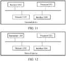
- an embodiment of the present application further provides a terminal device including: a processor, a memory, a receiver, and an interface for communicating with a network device; the memory stores computer executable instructions; and the processor executes the computer executable instructions stored in the memory to enable the processor to perform the method as described in the first aspect.
- the processor may be a chip.
- an embodiment of the present application provides a network device including: a processor, a memory, a transmitter, and an interface for communicating with a terminal device; the memory stores computer executable instructions; and the processor executes the computer executable instructions stored in the memory to enable the processor to perform the method as described in the second aspect.
- the processor may be a chip.
- an embodiment of the present application further provides a computer-readable storage medium having computer executable instructions stored thereon, which, when executed by a processor, are used for implementing the method described in the first aspect.
- an embodiment of the present application further provides a computer-readable storage medium having computer executable instructions stored thereon, which, when executed by a processor, are used for implementing the method described in the second aspect.
- an embodiment of the present application provides a program, which, when executed by a processor, is used for performing the method as described in the first aspect.
- an embodiment of the present application provides a program, which, when executed by a processor, is used for performing the method as described in the second aspect.
- an embodiment of the present application provides a computer program product including program instructions, which are used for implementing the method as described in the first aspect.
- an embodiment of the present application provides a computer program product including program instructions, which are used for implementing the method as described in the second aspect.
- an embodiment of the present application provides a chip including a processing module capable of performing the method described in the first aspect and a communication interface.
- the chip also includes a storage module (e.g., a memory) used for storing instructions, the processing module is used for executing the instructions stored in the storage module, and the execution of the instructions stored in the storage module enables the processing module to perform the method described in the first aspect.
- a storage module e.g., a memory
- the processing module is used for executing the instructions stored in the storage module, and the execution of the instructions stored in the storage module enables the processing module to perform the method described in the first aspect.
- an embodiment of the present application provides a chip including a processing module capable of performing the method described in the second aspect and a communication interface.
- the chip also includes a storage module (e.g., a memory) used for storing instructions, the processing module is used for executing the instructions stored in the storage module, and the execution of the instructions stored in the storage module enables the processing module to perform the method described in the second aspect.
- a storage module e.g., a memory
- the processing module is used for executing the instructions stored in the storage module, and the execution of the instructions stored in the storage module enables the processing module to perform the method described in the second aspect.
- the present application provides a communication system including a network device and a terminal device; the terminal device is the apparatus described in the third aspect, and the network device is the apparatus described in the fourth aspect.
- the device and the storage medium provided by the embodiments of the present application, the uplink transmission resources and the identifier of the HARQ process used for transmitting data on the uplink transmission resources are acquired, and then the set of candidate logical channels multiplexed on the uplink transmission resources is determined according to the HARQ feedback function state of the HARQ process and the HARQ feedback function attribute of each logical channel.
- the terminal device can select the multiplexed candidate logical channels to perform data transmission based on the QoS requirements of different services, thereby satisfying the requirements on transmission delay and/or reliability and improving the service experience of users.
- NTN non-terrestrial network
- 3GPP 3rd Generation Partnership Project
- Satellite communication refers to communication between two or more earth stations performed by forwarding or reflecting radio waves using artificial earth satellites as relay stations.
- satellite communication Compared with terrestrial cellular network communication, satellite communication has many unique advantages. Firstly, satellite communication is not limited by user regions. For example, general terrestrial communication cannot cover areas such as oceans, mountains, deserts, etc., where communication devices cannot be set up or communication coverage is not completed due to under-population, while for satellite communication, because a satellite can cover a larger ground and the satellite can orbit around the earth, theoretically every corner of the earth can be covered by satellite communication. Secondly, satellite communication has great social value. Satellite communication can cover remote mountainous areas and poor and backward countries or regions at a lower cost, so that people in these regions can enjoy advanced voice communication and mobile Internet technology, which is conducive to narrowing the digital divide with developed regions and promoting the development of these regions. Thirdly, the distance of satellite communication is long, and the increased communication cost due to the increased communication distance is not significant. Finally, the stability of satellite communication is high and will not be limited by natural disasters.
- FIG. 1 is a schematic structure diagram of a communications system in accordance with an embodiment of the present application.
- a network device and terminal devices 1 to 6 may form a communication system, in which any of the terminal devices 1 to 6 may transmit uplink data to the network device or receive downlink data transmitted by the network device.
- the terminal devices 4 to 6 may form a communication system, in which the terminal device 4 or 6 may transmit uplink data to the terminal device 5 or receive downlink data transmitted by the terminal device 5.
- the communication system shown in FIG. 1 may further include a communication satellite which may serve as a transfer station between at least one of the terminal devices 1 to 6 and the network device 1, to provide services for the terminal devices 1 to 6.
- a communication satellite which may serve as a transfer station between at least one of the terminal devices 1 to 6 and the network device 1, to provide services for the terminal devices 1 to 6.
- the terminal device may be any one of the terminal devices 1 to 6, and the network device may be a base station providing services for the terminal devices 1 to 6, or may be a communication satellite serving as a transfer station between the terminal devices 1 to 6 and the network device.
- the communication system may include a plurality of network devices, and other numbers of terminal devices may be included within the coverage area of each of the network devices.
- the numbers of network devices and terminal devices included in the communication system are not limited in the embodiments of the present application.
- the terminal devices can be connected to the network device wirelessly.
- wireless communication between the network device and a plurality of terminal devices may be established using an unlicensed spectrum.
- D2D device to device
- FIG. 1 is only a schematic diagram, and other network devices such as core network devices, wireless relay devices and wireless backhaul devices or other network entities such as network controllers, mobility management entities, etc., may also be included in the communication system, the embodiments of the present application are not limited thereto.
- network devices such as core network devices, wireless relay devices and wireless backhaul devices or other network entities such as network controllers, mobility management entities, etc.
- GSM global system of mobile communication
- CDMA code division multiple access
- WCDMA wideband code division multiple access
- GPRS general packet radio service
- LTE long term evolution
- FDD frequency division duplex
- TDD LTE time division duplex
- LTE-A advanced long term evolution
- NR new radio
- NR evolution system of an NR system
- LTE-U LTE-based access to unlicensed spectrum
- NR-U NR-based access to unlicensed spectrum
- UMTS universal mobile telecommunication system
- WiMAX worldwide interoperability for microwave access
- WLANs wireless local area networks
- WiFi wireless fidelity
- D2D device to device
- M2M machine to machine
- MTC machine type communication
- V2V vehicle to vehicle
- the network device involved in the embodiments of the present application may be an ordinary base station (e.g., a NodeB, or an eNB, or a gNB), a new radio controller (an NR controller), a centralized unit, a new radio base station, a radio remote unit, a micro base station, a relay, a distributed unit, a transmission reception point (TRP), a transmission point (TP), or any other device.
- a base station e.g., a NodeB, or an eNB, or a gNB
- a new radio controller an NR controller
- a centralized unit a new radio base station, a radio remote unit, a micro base station, a relay, a distributed unit, a transmission reception point (TRP), a transmission point (TP), or any other device.
- TRP transmission reception point
- TP transmission point
- Specific technologies and specific device forms used by the network device are not limited in the embodiments of the present application.
- the terminal devices may be any terminals, for example, the terminal devices may be user equipment for machine type communication. That is to say, the terminal devices may also be referred to as user equipment (UE), mobile stations (MSs), mobile terminals, terminals, etc.
- the terminal devices may communicate with one or more core networks via a radio access network (RAN).
- RAN radio access network
- the terminal devices may be mobile phones (or be referred to as "cellular" phones), computers with mobile terminals, etc.
- the terminal devices may also be portable, pocket-size, handheld, computer-built or vehicle-mounted mobile devices, and exchange speech and/or data with wireless access networks, which is not specifically limited in the embodiments of the present application.
- the network device and the terminal devices may be deployed on land, including indoors or outdoors, handheld or vehicle-mounted; or may be deployed on a water surface; or may be deployed on a plane, a balloon or an artificial satellite in the air.
- Application scenarios of the network device and the terminal devices are not limited in the embodiments of the present application.
- communications between the network device and the terminal devices and between the terminal devices may be established through a licensed spectrum, or an unlicensed spectrum, or both.
- Communications between the network device and the terminal devices and between the terminal devices may be established through a spectrum below 7 gigahertz (GHz), or a spectrum above 7GHz, or both.
- Spectrum resources used between the network device and the terminal devices are not limited in the embodiments of the present application.
- the communication satellites can be divided into geostationary earth orbit (GEO) satellites and non-geostationary earth orbit (Non-GEO) satellites according to orbital altitudes where the communication satellites providing services are located.
- the non-GEO satellites can be further divided into low earth orbit (LEO) satellites, medium-earth orbit (MEO) satellites and high elliptical orbit (HEO) satellites.
- LEO low earth orbit
- MEO medium-earth orbit
- HEO high elliptical orbit
- the LEO satellites and GEO satellites have become the main research objects in the field of global communication because of their low orbital altitudes and small propagation delays.
- the orbital altitude of a LEO satellite ranges from 500km to 1500km, and its orbit period is about 1.5 hours to 2 hours.
- the signal propagation delay of single-hop communication between the terminal device and the LEO is usually less than 20ms, and the maximum satellite visual time is 20 minutes. That is to say, the signal propagation distance between the terminal device and the LEO is short, the link loss is little, and the requirement on transmitting power of the terminal device is not high.
- the orbital altitude of a GEO satellite is 35786km, and its rotation period around the earth is 24 hours.
- the signal propagation delay of single-hop communication between the terminal device and the LEO is generally 250ms.
- the satellites use multiple beams to cover the ground.
- One satellite may form several tens or even hundreds of beams to cover the ground, and one satellite beam may cover a ground area with a diameter of several tens to hundreds of kilometers.
- the HARQ mechanism of the MAC layer is mainly for handling retransmission of lost or wrong data, and the ARQ mechanism of the RLC layer is mainly used to supplement the HARQ mechanism of the MAC layer.
- the HARQ mechanism of the MAC layer can provide fast retransmission, and the ARQ mechanism of the RLC layer can provide reliable data transmission.
- the HARQ mechanism uses a stop-and-wait protocol to transmit data.
- a transmitting end stops to wait for acknowledgement information after transmitting a transport block (TB).
- TB transport block
- the transmitting end stops to wait for acknowledgement after each transmission, which will lead to low throughput of users. Therefore, a plurality of parallel HARQ processes can be used in NR, and these HARQ processes together form an HARQ entity, which allows continuous transmission of data in combination with the stop-and-wait protocol, that is, when an HARQ process waits for the acknowledgement information, the transmitting end can use another HARQ process to continue transmitting data, thereby ensuring continuous transmission of data.
- HARQ can be divided into uplink HARQ and downlink HARQ.
- the uplink HARQ aims at uplink data transmission, and the downlink HARQ aims at downlink data transmission, and both are independent of each other.
- each serving cell corresponding to the terminal device has its own HARQ entity, and each HARQ entity maintains a set of parallel downlink HARQ processes and a set of parallel uplink HARQ processes.
- each uplink and downlink carrier supports up to 16 HARQ processes.
- the network device can indicate the maximum number of HARQ processes to the terminal device through semi-static configuration information, which is transmitted through radio resource control (RRC) signaling, according to network deployment situations. If the network device does not provide configuration parameters about HARQ, the number of default downlink HARQ processes is 8, and the maximum number of HARQ processes supported by each uplink carrier is always 16. Each HARQ process corresponds to one HARQ process ID.
- a broadcast control channel uses a dedicated broadcast HARQ process.
- Msg3 transmission in a random process uses HARQ ID 0.
- each downlink HARQ process can only process 1 TB at the same time; for a terminal device that supports downlink space division multiplexing, each downlink HARQ process can process one or two TBs at the same time. Each uplink HARQ process of the terminal device processes 1 TB at the same time.
- HARQ is divided into synchronous HARQ and asynchronous HARQ in the time domain and non-adaptive HARQ and adaptive HARQ in the frequency domain.
- An asynchronous adaptive HARQ mechanism is used in both uplink and downlink of NR.
- the asynchronous HARQ mechanism is that, retransmission can occur at any time, and a time interval between retransmission and last transmission of the same TB is not fixed.
- the adaptive HARQ mechanism can change frequency domain resources and a modulation and coding scheme (MCS) used in retransmission.
- MCS modulation and coding scheme
- the network i.e., network device
- the terminal device needs to determine the amount of transmission data of each logical channel in a media access control protocol data unit (MAC PDU) initially transmitted based on the uplink transmission resources configured by the network, and in some cases, the terminal device also needs to allocate resources for a media access control control element (MAC CE).
- MAC PDU media access control protocol data unit
- MAC CE media access control control element
- a priority needs to be assigned to each uplink logical channel.
- resources of the MAC PDU can be sequentially allocated in an order of logical channel priority corresponding to each uplink logical channel from high to low.
- PBR prioritized bit rate
- the network device can configure the following parameters for each uplink logical channel through radio resource control (RRC):
- RRC radio resource control
- the MAC of the terminal device implements multiplexing of the uplink logical channels using a token bucket mechanism, and the terminal device maintains a token number variable Bj for each uplink logical channel j, which indicates the number of tokens currently available in the token bucket, a maintaining method is as follows.
- A1 when the terminal device establishes the logical channel j, Bj is initialized to 0.
- A2 the terminal device increases Bj by PBR ⁇ T before each LCP process, wherein T is a time interval between the time point when Bj is increased last time and the current time point.
- A3 if Bj is updated according to the act A2 and the updated Bj is larger than the maximum capacity of the token bucket (i.e. PBR ⁇ BSD), the value of Bj is set as the maximum capacity of the token bucket.
- the terminal device when the terminal device receives a newly-transmitted UL grant from the network device, the terminal device can perform the logical channel prioritization processing according to the following acts.
- the terminal device sequentially allocates the resources to the logical channels in an order of logical channel priority from high to low using a given uplink transmission resource MAC PDU, wherein the resources allocated to each logical channel can only meet the requirements on PBR, that is, the number of tokens in the token bucket is determined according to the PBR corresponding to the logical channel j, and then the resources are allocated to the logical channel according to the number of tokens.
- PBR the number of tokens in the token bucket
- the resources that can be further allocated to the logical channels are updated, i.e., the size of all MAC service data units (SDU) of the logical channel j that are multiplexed onto the MAC PDU in Act1 is subtracted from Bj.
- SDU MAC service data units
- Act3 if there are still remaining uplink transmission resources after Act1 and Act2 have been performed, the remaining resources will be sequentially allocated to each logical channel in an order of logical channel priority from high to low regardless of the size of Bj. Only when data carried by the logical channels with high priority have been sent and UL grants have not been exhausted yet, the logical channels with low priority can be served, that is, at this moment the terminal device can guarantee data transmission of the logical channels with high priority to the maximum extent.
- the terminal device should also follow the following principles when transmitting data using the logical channels.
- the terminal device when the terminal device performs logical channel prioritization, it also needs to follow the following priority sequencing (arranged in an order of logical channel priority from high to low):
- the HARQ feedback function can be configured to be enabled/disabled (i.e., the HARQ function is enabled/disabled) based on the HARQ processes, i.e., for a plurality of HARQ processes of one terminal device, the HARQ feedback function of one part of the HARQ processes can be configured to be in an enabled state and the HARQ feedback function of another part of the HARQ processes can be configured to be in a disabled state.
- the network device can continue to schedule the HARQ process for data transmission without waiting receiving uplink transmission of the terminal device (which is uplink data transmission for the uplink HARQ and is ACK/NACK feedback for downlink data transmission of the terminal device for the downlink HARQ), thereby reducing the MAC transmission delay; on the other hand, if the network device no longer schedules the HARQ process for retransmission, MAC transmission reliability will be affected.
- Different services have different QoS requirements. For example, some services are sensitive to delay, and other services have strict requirements on packet loss rate. For the services which are sensitive to delay, transmission can be performed using an HARQ process of which an HARQ feedback function attribute is the disabled state, thereby reducing the transmission delay. For the services which have strict requirements on packet loss rate, transmission can be performed using an HARQ process of which the HARQ feedback function attribute is the enabled state, thereby improving transmission reliability.
- the network device when scheduling resources, can allocate the logical channels having different QoS requirements to different HARQ processes for transmission according to the QoS requirements of different logical channels.
- the network device For uplink transmission, the network device allocates the uplink transmission resources (for example, Physical Uplink Shared Channels (PUSCHs)) based on the terminal device, which logical channels are multiplexed on the uplink transmission resources allocated by the network device for transmitting data is determined by the terminal device. Specifically, the terminal device performs multiplexing of the logical channels based on the logical channel priority, prioritized bit rate, and token bucket depth.
- the uplink transmission resources for example, Physical Uplink Shared Channels (PUSCHs)
- PUSCHs Physical Uplink Shared Channels
- the terminal device does not consider the QoS requirements of different services in the uplink transmission process, and may not be able to meet the requirements on transmission delay and/or reliability, thereby affecting the service experience of users.
- an embodiment of the present application provides a method for channel processing, which includes acquiring the uplink transmission resources and an identifier of the HARQ process used for transmitting data on the uplink transmission resources, and then determining a set of candidate logical channels multiplexed on the uplink transmission resources according to an HARQ feedback function state of the HARQ process and an HARQ feedback function attribute of each logical channel.
- the terminal device can select the multiplexed candidate logical channels to perform data transmission based on the QoS requirements of different services, thereby satisfying the requirements on transmission delay and/or reliability and improving the service experience of users.
- the present application provides a method in which in the NTN, a network device configures attributes of the HARQ feedback function of each uplink logical channel, such as HARQ feedback function enabled, HARQ feedback function disabled, and HARQ feedback function enabled or disabled, and then based on the HARQ feedback function state of the HARQ process used when the data is transmitted on the uplink transmission resources and the attribute of the HARQ feedback function of each uplink logical channel, an appropriate set of candidate logical channels can be selected.
- attributes of the HARQ feedback function of each uplink logical channel such as HARQ feedback function enabled, HARQ feedback function disabled, and HARQ feedback function enabled or disabled
- the overall idea of the present application is that the terminal device completes multiplexing of the uplink logical channels according to the uplink transmission resources allocated by the network device.
- the main inventive point lies in that the network configures the attribute of HARQ feedback function enabled or HARQ feedback function disabled or HARQ feedback function enabled or disabled for the uplink logical channels according to the QoS requirements of services (such as delay, transmission reliability, etc.), and the terminal device determines different sets of candidate logical channels and processing of different logical channel priorities according to the HARQ feedback function state of the HARQ process used in the current uplink data transmission.
- FIG. 2 is a schematic flowchart of a first embodiment of a method for channel processing in accordance with the present application. The method is described with a terminal device being an execution body. As shown in FIG. 2 , the method for channel processing may include the following acts.
- first information is acquired, the first information including uplink transmission resources and an identifier of an HARQ process used for transmitting data on the uplink transmission resources.
- the terminal device when there is a data transmission requirement, can acquire the first information sent by a network device by sending a resource scheduling request to the network device, or acquire directly the first information pre-configured by the network device, or acquire the first information determined by the network device from other devices.
- the first information may include the uplink transmission resources (UL grants) and the identifier of the HARQ process used for transmitting data on the uplink transmission resources.
- the first information may also include indication information for indicating that this uplink transmission is an initial transmission.
- a set of candidate logical channels multiplexed on the uplink transmission resources is determined according to an HARQ feedback function state of the HARQ process and an HARQ feedback function attribute of each logical channel.
- the network device will configure relevant parameters for each logical channel, such as a logical channel priority, a prioritized bit rate, a token bucket size duration and an HARQ feedback function attribute of the logical channel. Meanwhile, the network device will also configure the number of uplink HARQ processes and the HARQ feedback function state of each uplink HARQ process for the terminal device. Therefore, in order to improve the usage experience of users, the terminal device can determine the set of candidate logical channels, which can be multiplexed in the uplink transmission process, according to the HARQ feedback function state of the HARQ process and the HARQ feedback function attribute of each logical channel.
- the set of candidate logical channels may include a logical channel, of which the HARQ feedback function attribute is consistent and/or partially consistent with the HARQ feedback function state of the HARQ process, among all logical channels in which there is currently data to be transmitted.
- the set of candidate logical channels may include a first set of candidate logical channels and a second set of candidate logical channels, wherein the first set of candidate logical channels includes a logical channel, of which the HARQ feedback function attribute is consistent and/or partially consistent with the HARQ feedback function state of the HARQ process, among all logical channels in which there is currently data to be transmitted; the second set of candidate logical channels includes a logical channel, of which the HARQ feedback function attribute is HARQ feedback function enabled or disabled, among all logical channels in which there is currently data to be transmitted.
- composition of the set of candidate logical channels may be any of the above-mentioned compositions, and will not be limited in the embodiments of the present application.
- the uplink transmission resources and the identifier of the HARQ process used for transmitting data on the uplink transmission resources are acquired, and then the set of candidate logical channels multiplexed on the uplink transmission resources is determined according to the HARQ feedback function state of the HARQ process and the HARQ feedback function attribute of each logical channel.
- the terminal device can select the multiplexed candidate logical channels to perform data transmission based on the QoS requirements of different services, thereby satisfying the requirements on transmission delay and/or reliability and improving the service experience of users.
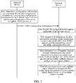
- FIG. 3 is a schematic interaction diagram of a second embodiment of a method for channel processing in accordance with the present application. The method is described with information interaction between the terminal device and the network device. As shown in FIG. 3 , the method for channel processing may include the following acts.
- a network device determines configuration information for a terminal device, the configuration information including first configuration information for each uplink logical channel and second configuration information for uplink HARQ processes.
- the first configuration information includes a logical channel priority, a prioritized bit rate, a token bucket size duration and an HARQ feedback function attribute.
- the second configuration information includes the number of uplink HARQ processes and an HARQ feedback function state of each HARQ process.
- the logical channel priority is used to characterize a precedence order by which the logical channels can be used.
- the logical channel with higher priority can be used preferentially.
- the prioritized bit rate is the minimum data rate configured for each logical channel in order to give consideration to the fairness between different logical channels.
- the token bucket size duration is primarily used to determine the depth of a token bucket and further determine the maximum capacity of the token bucket.
- the HARQ feedback function attribute is one of the following attributes: HARQ feedback function enabled, HARQ feedback function disabled, and HARQ feedback function enabled or disabled.
- the attribute of HARQ feedback function enabled means that the logical channel is suitable for multiplexing onto uplink transmission resources on which the HARQ feedback function is enabled
- the attribute of HARQ feedback function disabled means that the logical channel is suitable for multiplexing onto uplink transmission resources on which the HARQ feedback function is disabled
- the attribute of HARQ feedback function enabled or disabled means that the logical channel is suitable for multiplexing onto uplink transmission resources on which the HARQ feedback function is enabled or disabled.
- the network device in order to implement uplink transmission of data, needs to configure the number of HARQ processes used for uplink transmission for the terminal device. Further, in order to meet different QoS requirements of different services, in this embodiment, the network device can also determine the HARQ feedback function state of each HARQ process configured for the terminal device, so that the terminal device can select the appropriate HARQ processes based on different services' requirements on time delay and/or reliability.
- the network device can respectively configure the logical channel priority, the PBR, the BSD and the attribute of HARQ feedback function enabled or HARQ feedback function disabled or HARQ feedback function enabled or disabled for each uplink logical channel of the terminal device through the first configuration information.
- the network device can also configure the number of uplink HARQ processes and the HARQ feedback function state (enabled or disabled state) of each uplink HARQ process for the terminal device through the second configuration information.
- the network device transmits the configuration information to the terminal device.
- the network device after determining the configuration information for the terminal device, transmits the configuration information to the terminal device, so that the terminal device can know the attribute of each logical channel, the number of HARQ processes between the network device and the terminal device, and the HARQ feedback function state of each HARQ process.
- the network device can transmit the configuration information through radio resource control (RRC) signaling or MAC CE or through other signaling.
- RRC radio resource control
- the terminal device before performing the above-mentioned S201 (acquiring the first information), the terminal device may also perform the following acts.
- the terminal device acquires the configuration information transmitted by the network device.
- the terminal device can determine the HARQ feedback function attribute of each logical channel and the HARQ feedback function state of each HARQ process, both of which are determined based on the configuration information transmitted by the network device. Therefore, when there is an uplink data transmission requirement, the terminal device first needs to acquire the configuration information transmitted by the network device.
- the method for channel processing may further include the following acts.
- the terminal device allocates resources to each candidate logical channel according to the first configuration information for each candidate logical channel in the set of candidate logical channels.
- the terminal device can allocate the resources to each candidate logical channel based on the first configuration information for each candidate logical channel acquired from the network device, and then perform uplink transmission of the data through each candidate logical channel.
- the terminal device performs respectively a first round of resource allocation and a second round of resource allocation based on the logical channel priority, the PBR and the BSD of each candidate logical channel.
- the specific implementations regarding the first round of resource allocation and the second round of resource allocation can be understood with reference to the following contents, and will not be repeated herein.
- the network device determines the configuration information for the terminal device, and sends the configuration information to the terminal device.
- the configuration information includes the first configuration information for each uplink logical channel and the second configuration information for the uplink HARQ processes. Therefore, the terminal device can determine logical channels satisfying different service requirements, such that the QoS requirements of different services can be satisfied, thereby laying a foundation for improving the service experience of users.
- the set of candidate logical channels may be implemented using any of the following possible designs.
- the set of candidate logical channels includes a logical channel, of which the HARQ feedback function attribute is consistent and/or partially consistent with the HARQ feedback function state of the HARQ process, among all logical channels in which there is currently data to be transmitted.
- the set of candidate logical channels includes: a logical channel, of which the HARQ feedback function attribute is HARQ feedback function enabled, and a logical channel, of which the HARQ feedback function attribute is HARQ feedback function enabled or disabled, among all logical channels in which there is currently data to be transmitted.
- the set of candidate logical channels includes: a logical channel, of which the HARQ feedback function attribute is HARQ feedback function disabled, and a logical channel, of which the HARQ feedback function attribute is HARQ feedback function enabled or disabled, among all logical channels in which there is currently data to be transmitted.
- the terminal device for uplink transmission of the HARQ processes, of which the HARQ feedback function is enabled, the terminal device only multiplexes an uplink logical channel, of which the HARQ feedback function attribute is HARQ feedback function enabled or HARQ feedback function enabled or disabled, onto the uplink transmission resources in this transmission; for uplink transmission of the HARQ processes, of which the HARQ feedback function is disabled, the terminal device only multiplexes an uplink logical channel, of which the HARQ feedback function attribute is HARQ feedback function disabled or HARQ feedback function enabled or disabled, onto the uplink transmission resources in this transmission.
- the terminal device only multiplexes a logical channel, of which the HARQ feedback function attribute is consistent and/or partially consistent with the HARQ feedback function state of the HARQ process, and a logical channel, of which the HARQ feedback function attribute is HARQ feedback function enabled or disabled, such that different services' requirements on delay and/or reliability can be met, thereby avoiding the problem of poor user experience due to inconsistent service requirements existing in the prior channel multiplexing method.
- the above-mentioned S304 can be specifically implemented by the following act: allocating the resources to each candidate logical channel according to the prioritized bit rate, the logical channel priority, and the token bucket size duration of each candidate logical channel in the set of candidate logical channels.
- the terminal device allocates the resources to each candidate logical channel in the set of candidate logical channels according to the following acts, i.e., implements multiplexing of the logical channels.
- the candidate logical channels in this uplink transmission are determined.
- a logical channel, of which the HARQ feedback function attribute is HARQ feedback function disabled or HARQ feedback function enabled or disabled, is selected among all logical channels in which there is currently data to be transmitted.
- the first round of resource allocation is performed, that is, the resources satisfying the PBR are allocated to each candidate logical channel in the set of candidate logical channels.
- the resources are sequentially allocated in an order of logical channel priority from high to low.
- the resources allocated to each candidate logical channel can only meet the requirements on the PBR, that is, the number of tokens in the token bucket is determined according to the PBR corresponding to the candidate logical channel j, and then the resources are allocated to the candidate logical channel according to the number of tokens.
- the size of the candidate logical channel j multiplexed onto the uplink transmission resources in D12 is subtracted from Bj of the candidate logical channel j, i.e., the size of all MAC SDUs of the candidate logical channel j that are multiplexed onto an MAC PDU in D12 is subtracted from Bj of the candidate logical channel j.
- D14 for all the candidate logical channels determined in D11, if there are still remaining uplink transmission resources after the act D12 is performed, the remaining uplink transmission resources are sequentially allocated to each candidate logical channel in the set of candidate logical channels in an order of logical channel priority from high to low regardless of the size of Bj of each candidate logical channel.
- the terminal device allocates the resources to each candidate logical channel in the set of candidate logical channels according to the following acts.
- the candidate logical channels in this uplink transmission are determined, i.e., a logical channel, of which the HARQ feedback function attribute is HARQ feedback function disabled or HARQ feedback function enabled or disabled, is selected among all logical channels in which there is currently data to be transmitted.
- the first round of resource allocation is performed, that is, the resources satisfying the PBR are allocated to each candidate logical channel.
- the resources are sequentially allocated in an order of logical channel priority from high to low.
- the resources allocated to each candidate logical channel can only meet the requirements on the PBR, that is, the number Bj of tokens in the token bucket is determined according to the PBR corresponding to the candidate logical channel j, and then the resources are allocated to the candidate logical channel according to the number of tokens.
- the size of all MAC SDUs of the candidate logical channel j that are multiplexed onto an MAC PDU in D22 is subtracted from Bj of the candidate logical channel j.
- D24 for all the candidate logical channels determined in D21, if there are still remaining uplink transmission resources after the act D22 is performed, the remaining uplink transmission resources are sequentially allocated to each candidate logical channel in an order of logical channel priority from high to low regardless of the size of Bj of each candidate logical channel.
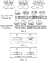
- FIG. 4 is a schematic diagram of HARQ feedback function attributes of logical channels that a terminal device has and a resource allocation of each logical channel.
- the terminal device has established four uplink logical channels in total, LC1, LC2, LC3 and LC4, respectively.
- the specific acts for the terminal device to perform logical channel selection and resource allocation are as follows.
- the terminal device receives radio resource control (RRC) configuration information transmitted by the network device.
- RRC radio resource control
- the terminal device receives the first information transmitted by the network device, the first information including the uplink transmission resources and HARQ ID 0 of the HARQ process used for transmitting data on the uplink transmission resources. Since the HARQ feedback function of HARQ ID 0 is in the enabled state, the terminal device completes multiplexing of the logical channels according to the following acts.
- LC1, LC3 and LC4 are selected as the candidate logical channels in this uplink transmission.
- the first round of resource allocation is performed, i.e., the resources satisfying the PBR are sequentially allocated to LC1, LC3 and LC4, and the numbers of tokens in PBR token buckets corresponding to LC1, LC3 and LC4 are updated according to the resource allocation result.
- the second round of resource allocation is performed, i.e., the remaining uplink transmission resources are sequentially allocated to LC1, LC3 and LC4 according to the mount of remaining data to be transmitted and the mount of remaining resources of the uplink transmission resources.
- the terminal device receives the first information transmitted by the network device, the first information including the uplink transmission resources and HARQ ID 1 of the HARQ process used for transmitting data on the uplink transmission resources, since the HARQ feedback function of HARQ ID 1 is in the disabled state, the terminal device completes multiplexing of the logical channels according to the following acts.
- LC2 and LC4 are selected as the candidate logical channels in this uplink transmission.
- the first round of resource allocation is performed, i.e., the resources satisfying the PBR are sequentially allocated to LC2 and LC4, and the numbers of tokens in PBR token buckets corresponding to LC2 and LC4 are updated according to the resource allocation result.
- the second round of resource allocation is performed, i.e., the remaining resources are sequentially allocated to LC2 and LC4 according to the mount of remaining data to be transmitted and the mount of remaining resources of the uplink transmission resources.
- the set of candidate logical channels includes a first set of candidate logical channels and a second set of candidate logical channels.
- the first set of candidate logical channels includes a logical channel, of which the HARQ feedback function attribute is consistent with the HARQ feedback function state of the HARQ process, among all logical channels in which there is currently data to be transmitted; and the second set of candidate logical channels includes a logical channel, of which the HARQ feedback function attribute is HARQ feedback function enabled or disabled, among all logical channels in which there is currently data to be transmitted.
- the first set of candidate logical channels includes a logical channel, of which the HARQ feedback function attribute is HARQ feedback function enabled, among all logical channels in which there is currently data to be transmitted.
- the first set of candidate logical channels includes a logical channel, of which the HARQ feedback function attribute is HARQ feedback function disabled, among all logical channels in which there is currently data to be transmitted.
- the terminal device divides the candidate logical channels into the first set of candidate logical channels and the second set of candidate logical channels with different candidate sequences based on the HARQ feedback function attributes and HARQ feedback function states of the logical channels.
- the terminal device first multiplexes the first set of candidate logical channels composed of the logical channels, of which the HARQ feedback function attributes are consistent with the HARQ feedback function state of the HARQ process, and then multiplexes the logical channels, of which the HARQ feedback function attributes are HARQ feedback function enabled or disabled, so that data transmission of the logic channels with consistent attributes can be guaranteed preferentially, and the resource utilization rate can be improved on this basis.
- the above-mentioned S304 may be specifically implemented by a first possible implementation or a second possible implementation.
- the terminal device for uplink transmission of an HARQ process in which the HARQ feedback function is enabled, preferentially multiplexes an uplink logical channel, of which the HARQ feedback function attribute is HARQ feedback function enabled, onto the uplink transmission resources in this transmission. If there are still remaining resources after each round of resource allocation (the first round of resource allocation and the second round of resource allocation) is performed, the terminal device continues to multiplex an uplink logical channel, of which the HARQ feedback function attribute is HARQ feedback function enabled/disabled, onto the uplink transmission resources in this transmission.
- the terminal device For uplink transmission of an HARQ process in which the HARQ feedback function is disabled, the terminal device preferentially multiplexes an uplink logical channel, of which the HARQ feedback function attribute is HARQ feedback function disabled, onto the uplink transmission resources in this transmission. If there are still remaining resources after each round of resource allocation is performed, the terminal device continues to multiplex an uplink logical channel, of which the HARQ feedback function attribute is HARQ feedback function enabled/disabled, onto the uplink transmission resources in this transmission.
- FIG. 5 is a schematic flowchart of a third embodiment of a method for channel processing in accordance with the present application.
- the set of candidate logical channels includes the first set of candidate logical channels and the second set of candidate logical channels
- the first possible implementation of S304 is specifically as follows.
- the first round of resource allocation is performed for each candidate logical channel in the first set of candidate logical channels and the second set of candidate logical channels respectively using uplink transmission resources.
- the first round of resource allocation includes a primary first round of resource allocation for the first set of candidate logical channels and a secondary first round of resource allocation for the second set of candidate logical channels.
- the terminal device firstly performs the primary first round of resource allocation for each candidate logical channel in the first set of candidate logical channels using the uplink transmission resources according to the prioritized bit rate, the logical channel priority, and the token bucket size duration of each candidate logical channel in the first set of candidate logical channels; secondly, if the uplink transmission resources are not fully allocated after the primary first round of resource allocation is performed, determines first uplink remaining transmission resources, and finally performs the secondary first round of resource allocation for each candidate logical channel in the second set of candidate logical channels using the first uplink remaining transmission resources according to the prioritized bit rate, the logical channel priority, and the token bucket size duration of each candidate logical channel in the second set of candidate logical channels.
- the terminal device first performs the primary first round of resource allocation in an order of logical channel priority from high to low.
- the resources allocated to each logical channel can only meet the requirements on the PBR.
- the candidate logical channel j to which the resources are allocated, in the first set of candidate logical channels, the size of all MAC SDUs of the candidate logical channel j that are multiplexed onto an MAC PDU in the primary first round of resource allocation, is subtracted from Bj of the candidate logical channel j.
- the secondary first round of resource allocation continues to be performed for the determined second set of candidate logical channels.
- the terminal device first performs the secondary first round of resource allocation in an order of logical channel priority from high to low, wherein the resources allocated to each logical channel can only meet the requirements on the PBR, and then, for the candidate logical channel j, to which the resources are allocated, in the second set of candidate logical channels, the size of all MAC SDUs of the candidate logical channel j that are multiplexed onto an MAC PDU in the secondary first round of resource allocation, is subtracted from Bj.
- the remaining uplink transmission resources are determined.
- the second round of resource allocation is performed for each candidate logical channel in the first set of candidate logical channels and the second set of candidate logical channels respectively using the remaining uplink transmission resources.
- the remaining uplink transmission resources are second uplink remaining transmission resources.
- the specific implementation of the act includes: performing sequentially a primary second round of resource allocation for each candidate logical channel in the first set of candidate logical channels in an order of logical channel priority from high to low using the second uplink remaining transmission resources; if the second uplink remaining transmission resources are not fully allocated after the primary second round of resource allocation is performed, determining third uplink remaining transmission resources; and finally performing sequentially a secondary second round of resource allocation for each candidate logical channel in the second set of candidate logical channels in an order of logical channel priority from high to low using the third uplink remaining transmission resources.
- the primary second round of resource allocation is performed for each candidate logical channel in the first set of candidate logical channels, that is, the remaining uplink transmission resources (second uplink remaining transmission resources) are sequentially allocated to each candidate logical channel in the first set of candidate logical channels in an order of logical channel priority from high to low regardless of the size of the token number variable Bj of each candidate logical channel.
- the secondary second round of resource allocation is performed for each candidate logical channel in the second set of candidate logical channels, that is, the remaining resources (third uplink remaining transmission resources) are sequentially allocated to each candidate logical channel in the second set of candidate logical channels in an order of logical channel priority from high to low regardless of the size of Bj.
- FIG. 6 is a schematic diagram of HARQ feedback function attributes of logical channels that a terminal device has and another resource allocation of each logical channel.
- the terminal device has established four uplink logical channels in total, LC1, LC2, LC3 and LC4, respectively.
- the specific acts for the terminal device to perform logical channel selection and resource allocation are as follows.
- the terminal device receives RRC configuration information transmitted by the network device.
- the logical channel priority of each logical channel that the terminal device has is LC1 > LC2 > LC3 > LC4, the attributes of LC1 and LC3 are HARQ feedback function enabled, the attribute of LC2 is HARQ feedback function disabled, and the attribute of LC4 is HARQ feedback function enabled/disabled.
- the terminal device has two uplink HARQ process numbers, HARQ ID 0 and HARQ ID 1 respectively, and the HARQ feedback function of HARQ ID 0 is in the enabled state, and the HARQ feedback function of HARQ ID 1 is in the disabled state.
- the terminal device receives the first information transmitted by the network device, the first information including the uplink transmission resources and HARQ ID 0 of the HARQ process used for transmitting data on the uplink transmission resources. Since the HARQ feedback function of HARQ ID 0 is in the enabled state, the terminal device completes multiplexing of the logical channels according to the following acts.
- LC1 and LC3 are selected as the first set of candidate logical channels in this uplink transmission, and LC4 is selected as the second set of candidate logical channels in this uplink transmission.
- the first round of resource allocation is performed, i.e., the terminal device first allocates the resources satisfying the PBR to LC1 and LC3 (the primary first round of resource allocation), and updates the numbers of tokens in PBR token buckets corresponding to LC1 and LC3 according to the resource allocation result; if there are still remaining uplink transmission resources after the primary first round of resource allocation is performed, the terminal device continues to allocate the resources satisfying the PBR to LC4 (the secondary first round of resource allocation), and updates the number of tokens in a PBR token bucket corresponding to LC4 according to the resource allocation result.
- the second round of resource allocation is performed, i.e., the terminal device first allocates the remaining uplink transmission resources to LC1 and LC3 (the primary second round of resource allocation), and then allocates the resources to LC4 (the secondary second round of resource allocation) if there are still remaining uplink transmission resources after the primary second round of resource allocation is performed.
- the terminal device receives the first information transmitted by the network device, the first information including the uplink transmission resources and HARQ ID 1 of the HARQ process used when the data is transmitted on the uplink transmission resources, since the HARQ feedback function of HARQ ID 1 is in the disabled state, the terminal device completes multiplexing of the logical channels according to the following acts.
- LC2 is selected as the first set of candidate logical channels in this uplink transmission
- LC4 is selected as the second set of candidate logical channels in this uplink transmission.
- the first round of resource allocation is performed, i.e., the terminal device allocates the resources satisfying the PBR to LC2 (the primary first round of resource allocation), and updates the number of tokens in a PBR token bucket corresponding to LC2 according to the resource allocation result. If there are still remaining uplink transmission resources after the primary first round of resource allocation is performed, the terminal device continues to allocate the resources satisfying the PBR to LC4 (the secondary first round of resource allocation), and updates the number of tokens in the PBR token bucket corresponding to LC4 according to the resource allocation result.
- the second round of resource allocation is performed, i.e., the terminal device allocates the remaining uplink transmission resources to LC2 (the primary second round of resource allocation), and then allocates the resources to LC4 (the secondary second round of resource allocation) if there are still remaining uplink transmission resources after the primary second round of resource allocation is performed.
- the terminal device first performs the first round of resource allocation for each candidate logical channel in the first set of candidate logical channels and the second set of candidate logical channels respectively using the uplink transmission resources. If the uplink transmission resources are not fully allocated after the first round of resource allocation is performed, the terminal device determines the remaining uplink transmission resources, and finally performs the second round of resource allocation for each candidate logical channel in the first set of candidate logical channels and the second set of candidate logical channels respectively using the remaining uplink transmission resources.
- the terminal device first multiplexes the first set of candidate logical channels, and then multiplexes the second set of candidate logical channels, so that data transmission of the logical channels with consistent attributes can be guaranteed preferentially. Further, the resource utilization rate can be improved through the first round of resource allocation and the second round of resource allocation, thereby improving the service experience of users.
- the terminal device for uplink transmission of an HARQ process in which the HARQ feedback function is enabled, preferentially multiplexes an uplink logical channel (the first set of candidate logical channels), of which the HARQ feedback function attribute is HARQ feedback function enabled, onto the uplink transmission resources in this transmission, and if there are still remaining resources after the second round of resource allocation is performed, the terminal device continues to multiplex an uplink logical channel (the second set of candidate logical channels), of which the HARQ feedback function attribute is HARQ feedback function enabled /disabled, onto the uplink transmission resources in this transmission.
- the terminal device preferentially multiplexes an uplink logical channel (the first set of candidate logical channels), of which the HARQ feedback function attribute is HARQ feedback function enabled, onto the uplink transmission resources in this transmission, and if there are still remaining resources after the second round of resource allocation is performed, the terminal device continues to multiplex an uplink logical channel (the second set of candidate logical channels), of which the HARQ feedback function attribute is
- the terminal device for uplink transmission of the HARQ process in which the HARQ feedback function is disabled, preferentially multiplexes an uplink logical channel, of which the HARQ feedback function attribute is HARQ feedback function disabled, onto the uplink transmission resources in this transmission, and if there are still remaining resources after the second round of resource allocation is performed, the terminal device continues to multiplex an uplink logical channel, of which the HARQ feedback function attribute is HARQ feedback function enabled/disabled, onto the uplink transmission resources in this transmission.
- FIG. 7 is a schematic flowchart of a fourth embodiment of a method for channel processing in accordance with the present application.
- the set of candidate logical channels includes the first set of candidate logical channels and the second set of candidate logical channels
- the second possible implementation of S304 is specifically as follows.
- the primary first round of resource allocation and the primary second round of resource allocation are performed for each candidate logical channel in the first set of candidate logical channels using the uplink transmission resources.
- the terminal device firstly performs the primary first round of resource allocation for each candidate logical channel in the first set of candidate logical channels using the uplink transmission resources according to the prioritized bit rate, the logical channel priority, and the token bucket size duration of each candidate logical channel in the first set of candidate logical channels. Secondly, if the uplink transmission resources are not fully allocated after the primary first round of resource allocation is performed, the terminal device determines fourth uplink remaining transmission resources. And finally the terminal device performs the primary second round of resource allocation sequentially for each candidate logical channel in the first set of candidate logical channels in an order of logical channel priority from high to low using the fourth uplink remaining transmission resources.
- the terminal device first performs the primary first round of resource allocation in an order of logical channel priority from high to low, wherein the resources allocated to each logical channel can only meet the requirements on the PBR. And then, for the candidate logical channel j, to which the resources are allocated, in the first set of candidate logical channels, the terminal device updates the number of tokens in the PBR token bucket corresponding to each candidate logical channel in the first set of candidate logical channels according to the resource allocation result.
- the remaining uplink transmission resources are sequentially allocated to each candidate logical channel in the first set of candidate logical channels in an order of logical channel priority from high to low (the primary second round of resource allocation) regardless of the size of the token number variable Bj of each candidate logical channel in the first set of candidate logical channels.
- the remaining uplink transmission resources are determined.
- the secondary first round of resource allocation and the secondary second round of resource allocation are performed sequentially for each candidate logical channel in the second set of candidate logical channels using the remaining uplink transmission resources.
- the remaining uplink transmission resources are fifth uplink remaining transmission resources.
- the specific implementation of the act includes: the terminal device first performs the secondary first round of resource allocation for each candidate logical channel in the second set of candidate logical channels using the fifth uplink remaining transmission resources according to the prioritized bit rate, the logical channel priority, and the token bucket size duration of each candidate logical channel in the second set of candidate logical channels; secondly, if the fifth uplink remaining transmission resources are not fully allocated after the secondary second round of resource allocation is performed, determines sixth uplink remaining transmission resources; and finally performs sequentially the secondary second round of resource allocation for each candidate logical channel in the second set of candidate logical channels using the sixth uplink remaining transmission resources in an order of logical channel priority from high to low.
- the secondary first round of resource allocation and the secondary second round of resource allocation are performed for each candidate logical channel in the second set of candidate logical channels.
- FIG. 8 is a schematic diagram of HARQ feedback function attributes of logical channels that a terminal device has and still another resource allocation of each logical channel.
- the terminal device has established four uplink logical channels in total, LC1, LC2, LC3 and LC4, respectively.
- the specific acts for the terminal device to perform logical channel selection and resource allocation are as follows.
- the terminal device receives RRC configuration information transmitted by the network device.
- the logical channel priority of each logical channel that the terminal device has is LC1 > LC2 > LC3 > LC4, the attributes of LC1 and LC3 are HARQ feedback function enabled, the attribute of LC2 is HARQ feedback function disabled, and the attribute of LC4 is HARQ feedback function enabled/disabled.
- the terminal device has two uplink HARQ process numbers, HARQ ID 0 and HARQ ID 1 respectively, and the HARQ feedback function of HARQ ID 0 is in the enabled state, and the HARQ feedback function of HARQ ID 1 is in the disabled state.
- the terminal device receives the first information transmitted by the network device, the first information including the uplink transmission resources and HARQ ID 0 of the HARQ process used for transmitting data on the uplink transmission resources. Since the HARQ feedback function of HARQ ID 0 is in the enabled state, the terminal device completes multiplexing of the logical channels according to the following acts.
- LC1 and LC3 are selected as the first set of candidate logical channels in this uplink transmission, and LC4 is selected as the second set of candidate logical channels in this uplink transmission.
- the primary first round of resource allocation and the primary second round of resource allocation are performed, i.e., the terminal device allocates the resources satisfying the PBR to LC1 and LC3 (the primary first round of resource allocation), and updates the numbers of tokens in PBR token buckets corresponding to LC1 and LC3 according to the resource allocation result; if there are still remaining uplink transmission resources after the primary first round of resource allocation is performed, the terminal device sequentially allocates the remaining uplink transmission resources to LC1 and LC3 in an order of logical channel priority from high to low (the primary second round of resource allocation) regardless of the size of Bj of LC1 or LC3.
- the secondary first round of resource allocation and the secondary second round of resource allocation are performed, i.e., if there are still remaining uplink transmission resources after the terminal device performs respectively the primary first round of resource allocation and the primary second round of resource allocation for LC1 and LC3, the terminal device allocates the resources, i.e., the resources satisfying the PBR, to LC4 (the secondary first round of resource allocation), and updates the number of tokens in the PBR token bucket corresponding to LC4 according to the resource allocation result; if there are still remaining uplink transmission resources after the secondary first round of resource allocation is performed, the terminal device allocates the remaining uplink transmission resources to LC4 (the secondary second round of resource allocation) regardless of the size of Bj of LC4.
- the terminal device receives the first information transmitted by the network device, the first information including the uplink transmission resources and HARQ ID 1 of the HARQ process used for transmitting data on the uplink transmission resources, since the HARQ feedback function of HARQ ID 1 is in the disabled state, the terminal device completes multiplexing of the logical channels according to the following acts.
- LC2 is selected as the first set of candidate logical channels in this uplink transmission
- LC4 is selected as the second set of candidate logical channels in this uplink transmission.
- the primary first round of resource allocation and the primary second round of resource allocation are performed, i.e., the terminal device allocates the resources satisfying the PBR to LC2 (the primary first round of resource allocation), and updates the number of tokens in a PBR token bucket corresponding to LC2 according to the resource allocation result; and if there are still remaining uplink transmission resources after the primary first round of resource allocation is performed, the terminal device allocates the remaining uplink transmission resources to LC2 regardless of the size of Bj of LC2.
- the secondary first round of resource allocation and the secondary second round of resource allocation are performed, i.e., the terminal device allocates the resources satisfying the PBR to LC4, and updates the number of tokens in a PBR token bucket corresponding to LC4 according to the resource allocation result; and if there are still remaining uplink transmission resources after the secondary first round of resource allocation is performed, the terminal device allocates the remaining uplink transmission resources to LC4 regardless of the size of LC4.
- the terminal device first performs the primary first round of resource allocation and the primary second round of resource allocation for each candidate logical channel in the first set of candidate logical channels using the uplink transmission resources, secondly, if the uplink transmission resources are not fully allocated after the primary first round of resource allocation and the primary second round of resource allocation are performed, the terminal device determines the remaining uplink transmission resources, and finally performs sequentially the secondary first round of resource allocation and the secondary second round of resource allocation for each candidate logical channel in the second set of candidate logical channels using the remaining uplink transmission resources.
- the terminal device first multiplexes the first set of candidate logical channels to the maximum extent, and then multiplexes the second set of candidate logical channels, so that data transmission of the logical channels with consistent attributes can be guaranteed preferentially to the maximum extent, thereby meeting the different QoS requirements of various services to the maximum extent.
- the terminal device can configure the attribute of whether the HARQ function is enabled/disabled in each HARQ process based on the HARQ process in the NTN.
- An embodiment of the present application provides a method in which in the NTN, the terminal device performs logical channel prioritization according to the uplink transmission resources allocated by the network device, so as to implement multiplexing of the uplink logical channels. Different QoS requirements of various services can be well met by using this method, improving the service experience of users.
- FIG. 9 is a schematic structure diagram of a first embodiment of an apparatus for channel processing in accordance with the present application.
- the apparatus can be integrated in or implemented by a terminal device.
- the apparatus may include an acquiring module 901 and a processing module 902.
- the acquiring module 901 is configured to acquire first information, the first information including uplink transmission resources and an identifier of an HARQ process used for transmitting data on the uplink transmission resources.
- the processing module 902 is configured to determine a set of candidate logical channels multiplexed on the uplink transmission resources according to an HARQ feedback function state of the HARQ process and an HARQ feedback function attribute of each logical channel.
- the acquiring module 901 is further configured to acquire configuration information transmitted by a network device before acquiring the first information, the configuration information including first configuration information for each uplink logical channel of the terminal device and second configuration information for uplink HARQ processes.
- the first configuration information includes a logical channel priority, a prioritized bit rate, a token bucket size duration, and an HARQ feedback function attribute.
- the second configuration information includes the number of uplink HARQ processes and an HARQ feedback function state of each HARQ process.
- the HARQ feedback function attribute is one of the following attributes: HARQ feedback function enabled, HARQ feedback function disabled, and HARQ feedback function enabled or disabled.
- the processing module 902 is further configured to allocate resources to each candidate logical channel according to the first configuration information for each candidate logical channel in the set of candidate logical channels.
- the set of candidate logical channels includes a logical channel, of which the HARQ feedback function attribute is consistent and/or partially consistent with the HARQ feedback function state of the HARQ process, among all logical channels in which there is currently data to be transmitted.
- the set of candidate logical channels includes: a logical channel, of which the HARQ feedback function attribute is HARQ feedback function enabled, and a logical channel, of which the HARQ feedback function attribute is HARQ feedback function enabled or disabled, among all logical channels in which there is currently data to be transmitted.
- the set of candidate logical channels includes: a logical channel, of which the HARQ feedback function attribute is HARQ feedback function disabled, and a logical channel, of which the HARQ feedback function attribute is HARQ feedback function enabled or disabled, among all logical channels in which there is currently data to be transmitted.
- the processing module 902 is configured to allocate the resources to each candidate logical channel according to the first configuration information for each candidate logical channel in the set of candidate logical channels, specifically including: the processing module 902 is specifically configured to allocate the resources to each candidate logical channel according to the prioritized bit rate, the logical channel priority, and the token bucket size duration of each candidate logical channel in the set of candidate logical channels.
- the set of candidate logical channels includes a first set of candidate logical channels and a second set of candidate logical channels.
- the first set of candidate logical channels includes a logical channel, of which the HARQ feedback function attribute is consistent with the HARQ feedback function state of the HARQ process, among all logical channels in which there is currently data to be transmitted.
- the second set of candidate logical channels includes a logical channel, of which the HARQ feedback function attribute is HARQ feedback function enabled or disabled, among all logical channels in which there is currently data to be transmitted.
- the first set of candidate logical channels includes a logical channel, of which the HARQ feedback function attribute is HARQ feedback function enabled, among all logical channels in which there is currently data to be transmitted.
- the first set of candidate logical channels includes a logical channel, of which the HARQ feedback function attribute is HARQ feedback function disabled, among all logical channels in which there is currently data to be transmitted.
- the processing module 902 is configured to allocate the resources to each candidate logical channel according to the first configuration information for each candidate logical channel in the set of candidate logical channels, specifically including: the processing module 902 is specifically configured to perform a first round of resource allocation for each candidate logical channel in the first set of candidate logical channels and the second set of candidate logical channels respectively using the uplink transmission resources, if the uplink transmission resources are not fully allocated after the first round of resource allocation is performed, determine remaining uplink transmission resources, and perform a second round of resource allocation for each candidate logical channel in the first set of candidate logical channels and the second set of candidate logical channels respectively using the remaining uplink transmission resources.
- the processing module 902 is configured to perform the first round of resource allocation for each candidate logical channel in the first set of candidate logical channels and the second set of candidate logical channels respectively using the uplink transmission resources, specifically including: the processing module 902 is specifically configured to perform a primary first round of resource allocation for each candidate logical channel in the first set of candidate logical channels using the uplink transmission resources according to the prioritized bit rate, the logical channel priority, and the token bucket size duration of each candidate logical channel in the first set of candidate logical channels, if the uplink transmission resources are not fully allocated after the primary first round of resource allocation is performed, determine first uplink remaining transmission resources, and perform a secondary first round of resource allocation for each candidate logical channel in the second set of candidate logical channels according to the prioritized bit rate, the logical channel priority, and the token bucket size duration of each candidate logical channel in the second set of candidate logical channels using the first uplink remaining transmission resources.
- the remaining uplink transmission resources are second uplink remaining transmission resources.
- the processing module 902 is configured to perform the second round of resource allocation for each candidate logical channel in the first set of candidate logical channels and the second set of candidate logical channels respectively using the remaining uplink transmission resources, specifically including: the processing module 902 is specifically configured to perform sequentially a primary second round of resource allocation for each candidate logical channel in the first set of candidate logical channels in an order of logical channel priority from high to low using the second uplink remaining transmission resources, if the second uplink remaining transmission resources are not fully allocated after the primary second round of resource allocation is performed, determine third uplink remaining transmission resources, and perform sequentially a secondary second round of resource allocation for each candidate logical channel in the second set of candidate logical channels in an order of logical channel priority from high to low using the third uplink remaining transmission resources.
- the processing module 902 is configured to allocate the resources to each candidate logical channel according to the first configuration information for each candidate logical channel in the set of candidate logical channels, specifically including: the processing module 902 is specifically configured to perform the primary first round of resource allocation and the primary second round of resource allocation for each candidate logical channel in the first set of candidate logical channels using the uplink transmission resources, if the uplink transmission resources are not fully allocated after the primary first round of resource allocation and the primary second round of resource allocation are performed, determine the remaining uplink transmission resources, and perform sequentially the secondary first round of resource allocation and the secondary second round of resource allocation for each candidate logical channel in the second set of candidate logical channels using the remaining uplink transmission resources.
- the processing module 902 is configured to perform the primary first round of resource allocation and the primary second round of resource allocation for each candidate logical channel in the first set of candidate logical channels using the uplink transmission resources, specifically including: the processing module 902 is specifically configured to perform the primary first round of resource allocation for each candidate logical channel in the first set of candidate logical channels using the uplink transmission resources according to the prioritized bit rate, the logical channel priority, and the token bucket size duration of each candidate logical channel in the first set of candidate logical channels, if the uplink transmission resources are not fully allocated after the primary first round of resource allocation is performed, determine fourth uplink remaining transmission resources, and perform sequentially the primary second round of resource allocation for each candidate logical channel in the first set of candidate logical channels in an order of logical channel priority from high to low using the fourth uplink remaining transmission resources.
- the remaining uplink transmission resources are fifth uplink remaining transmission resources.
- the processing module 902 is configured to perform sequentially the secondary first round of resource allocation and the secondary second round of resource allocation for each candidate logical channel in the second set of candidate logical channels using the remaining uplink transmission resources, specifically including: the processing module 902 is specifically configured to perform the secondary first round of resource allocation for each candidate logical channel in the second set of candidate logical channels using the fifth uplink remaining transmission resources according to the prioritized bit rate, the logical channel priority, and the token bucket size duration of each candidate logical channel in the second set of candidate logical channels, if the fifth uplink remaining transmission resources are not fully allocated after the secondary second round of resource allocation is performed, determine sixth uplink remaining transmission resources, and perform sequentially the secondary second round of resource allocation for each candidate logical channel in the second set of candidate logical channels in an order of logical channel priority from high to low using the sixth uplink remaining transmission resources.
- the apparatus provided by this embodiment is used for performing the technical solutions of the terminal device side in the embodiments shown in FIGs. 2 to 7 , implementation principles and technical effects thereof are similar and will not be repeated herein.
- FIG. 10 is a schematic structure diagram of a second embodiment of an apparatus for channel processing in accordance with the present application.
- the apparatus can be integrated in or implemented by a network device.
- the apparatus may include a determining module 1001 and a transmitting module 1002.
- the determining module 1001 is configured to determine configuration information for a terminal device, the configuration information including first configuration information for each uplink logical channel and second configuration information for uplink HARQ processes.
- the transmitting module 1001 is configured to transmit the configuration information to a terminal device.
- the first configuration information includes a logical channel priority, a prioritized bit rate, a token bucket size duration, and an HARQ feedback function attribute.
- the second configuration information includes the number of uplink HARQ processes and an HARQ feedback function state of each HARQ process.
- the HARQ feedback function attribute is one of the following attributes: HARQ feedback function enabled, HARQ feedback function disabled, and HARQ feedback function enabled or disabled.
- the division of various modules of the apparatus described above is only a logical function division.
- the modules can be fully or partially integrated into one physical entity or physically separated in the actual implementation. All the modules can be implemented by invoking software through a processing element; or all the modules can be implemented in the form of hardware; or some of the modules can be implemented by invoking software through the processing element, and the other modules can be implemented in the form of hardware.
- the processing module or the determining module can be a separately established processing element, or can be integrated in a certain chip of the apparatus, or can be stored in a memory of the apparatus in the form of a program code. Functions of the determining module can be invoked and executed by a certain processing element of the apparatus.
- the implementation of other modules is similar.
- all or part of these modules can be integrated together or implemented independently.
- the processing element described herein can be an integrated circuit having a signal processing capability.
- all acts of the methods described above or various modules described above can be accomplished by integrated logic circuits of hardware in the processing element or instructions in the form of software.
- the modules described above can be one or more integrated circuits, such as one or more application specific integrated circuits (ASICs), or one or more microprocessors (DSPs), or one or more field programmable gate arrays (FPGAs), etc., which are configured to implement the methods described above.
- ASICs application specific integrated circuits
- DSPs microprocessors
- FPGAs field programmable gate arrays
- a processing element which may be a general purpose processor, such as a central processing unit (CPU) or another processor that can invoke the program codes.
- these modules can be integrated together and implemented in the form of system-on-chip (SOC).
- the above-mentioned embodiments can be implemented in whole or in part through software, hardware, firmware, or any combination thereof.
- When implemented through software they can be implemented in whole or in part in the form of a computer program product.
- the computer program product includes one or more computer instructions.
- the computer program instructions When the computer program instructions are loaded to and executed on a computer, the processes or functions described according to the embodiments of the present application will be generated in whole or in part.
- the computer may be a general purpose computer, a special purpose computer, a computer network or another programmable apparatus.
- the computer instructions can be stored in a computer-readable storage medium or transmitted from one computer-readable storage medium to another computer-readable storage medium, for example, the computer instructions can be transmitted from one website site, computer, server or data center to another website site, computer, server or data center in a wired (e.g., coaxial cable, optical fiber, digital subscriber line (DSL)) or wireless (e.g., infrared, wireless, microwave and the like) manner.
- the computer-readable storage medium may be any available medium which the computer can access to, or a data storage device such as a server or data center having one or more available media integrated therein.
- the available medium may be a magnetic medium (e.g., floppy disk, hard disk, magnetic tape), an optical medium (e.g., DVD), or a semiconductor medium (e.g., solid state disk (SSD)).
- FIG. 11 is a schematic structure diagram of an embodiment of a terminal device in accordance with the present application.
- the terminal device may include a processor 1101, a memory 1102, a receiver 1103, and an interface 1104 for communicating with a network device.
- the memory 1102 is used for storing computer executable instructions; the receiver 1103 is used for communicating with other devices via the interface 1104, and the processor 1101 executes the computer executable instructions stored in the memory 1102, so that the processor 1101 performs the technical solutions of the terminal device side in the aforementioned embodiments shown in FIGs. 2 to 7 .
- FIG. 12 is a schematic structure diagram of an embodiment of a network device in accordance with the present application.
- the network device may include a processor 1201, a memory 1202, a transmitter 1203, and an interface 1204 for communicating with a terminal device.
- the memory 1202 is used for storing computer executable instructions; the transmitter 1203 is used for communicating with other devices via the interface 1204, and the processor 1201 executes the computer executable instructions stored in the memory 1202, so that the processor 1201 performs the technical solutions of the network device side in the aforementioned embodiments shown in FIGs. 2 to 7 .
- the present application also provides a communication system, which includes a network device and a terminal device.
- the terminal device may be the channel processing apparatus shown in FIG. 9 or the terminal device shown in FIG. 11
- the network device may be the channel processing apparatus shown in FIG. 10 or the network device shown in FIG. 12 .
- the specific implementation of the terminal device and the network device can be understood with reference with records in the above embodiments and will not be repeated herein.
- the present application further provides a computer-readable storage medium having computer executable instructions stored thereon, which, when executed by a processor, are used for implementing the technical solutions of the terminal device side in any one of the method embodiments described above.
- the present application further provides a computer-readable storage medium having computer executable instructions stored thereon, which, when executed by a processor, are used for implementing the technical solutions of the network device side in any one of the method embodiments described above.
- An embodiment of the present application further provides a program, which, when executed by a processor, is used for performing the technical solutions of the terminal device side in any one of the method embodiments described above.
- An embodiment of the present application further provides a program, which, when executed by a processor, is used for performing the technical solutions of the network device (base station) side in any one of the method embodiments described above.
- An embodiment of the present application further provides a computer program product including program instructions, which are used for implementing the technical solutions of the terminal device side in any one of the method embodiments described above.
- An embodiment of the present application further provides a computer program product including program instructions, which are used for implementing the technical solutions of the network device (base station) side in any one of the method embodiments described above.
- An embodiment of the present application further provides a chip including a processing module capable of performing the technical solutions of the terminal device side in any one of the method embodiments described above and a communication interface.
- the chip also includes a storage module (e.g., a memory) used for storing instructions, the processing module is used for executing the instructions stored in the storage module, and the execution of the instructions stored in the storage module causes the processing module to perform the technical solutions of the terminal device side in any one of the method embodiments described above.
- a storage module e.g., a memory
- the processing module is used for executing the instructions stored in the storage module, and the execution of the instructions stored in the storage module causes the processing module to perform the technical solutions of the terminal device side in any one of the method embodiments described above.
- An embodiment of the present application further provides a chip including a processing module capable of performing the technical solutions of the network device (base station) side in any one of the method embodiments described above and a communication interface.
- the chip also includes a storage module (e.g., a memory) used for storing instructions, the processing module is used for executing the instructions stored in the storage module, and the execution of the instructions stored in the storage module causes the processing module to perform the technical solutions of the network device side in any one of the method embodiments described above.
- a storage module e.g., a memory
- the processing module is used for executing the instructions stored in the storage module, and the execution of the instructions stored in the storage module causes the processing module to perform the technical solutions of the network device side in any one of the method embodiments described above.
- the disclosed system, apparatus, and method may be implemented in other ways.
- the apparatus embodiments described above are only illustrative.
- the division of the units is only a logical function division, and other division manners may be possible in the actual implementation.
- multiple units or components may be combined or integrated into another system, or some features may be ignored or not executed.
- coupling or direct coupling or communication connection shown or discussed between each other which may be indirect coupling or communication connection between the devices or units via some interfaces, may be electrical, mechanical, or in other forms.
- the processor may be a central processing unit (CPU), or another general purpose processor such as a digital signal processor (DSP), an application specific integrated circuit (ASIC), and the like.
- the general purpose processor may be a microprocessor or the processor may be any conventional processor.
- the acts of the methods disclosed in conjunction with the embodiments of the present application may be directly embodied to be completed by a hardware processor or by a combination of hardware and software modules in the processor.
- the aforementioned program can be stored in a readable memory.
- the program when executed, performs the acts of the method embodiments described above.
- the aforementioned memory storage medium includes a read-only memory (ROM), a RAM, a flash memory, a hard disk, a solid state disk, a magnetic tape, a floppy disk, an optical disk and any combination thereof.
Landscapes
- Engineering & Computer Science (AREA)
- Signal Processing (AREA)
- Computer Networks & Wireless Communication (AREA)
- Quality & Reliability (AREA)
- Mobile Radio Communication Systems (AREA)
Abstract
Description
- Embodiments of the present application relate to the field of communication technologies, and more particularly, to a channel processing method and apparatus, a device, and a storage medium.
- In a non-terrestrial network (NTN) system, with regards to the characteristic that the signal propagation delay between a terminal device and a satellite increases greatly, the way to disable a hybrid automatic repeat request (HARQ) function has been developed to reduce the data transmission delay.
- At present, in a downlink transmission process, in order to meet the quality of service (QoS) requirements of different services, a network device can allocate logical channels with different QoS requirements to different HARQ processes for transmission according to the QoS requirements of the logical channels upon scheduling. In an uplink transmission process, the network device allocates uplink transmission resources based on the terminal device, and which logical channels are multiplexed on the allocated uplink transmission resources for transmitting data is determined by the terminal device. Specifically, the terminal device performs multiplexing of the logical channels based on a logical channel priority, a prioritized bit rate, a token bucket depth, etc.
- However, for an HARQ process in which an HARQ feedback function is disabled and an HARQ process in which the HARQ feedback function is enabled, there is no set of rules at present yet to stipulate how to complete multiplexing of uplink logical channels, that is, the terminal device does not consider the QoS requirements of different services in the uplink transmission process, and the requirements on transmission delay and/or reliability may not be met.
- Embodiments of the present application provide a channel processing method and apparatus, a device, and a storage medium, so as to solve the problem that the requirements on transmission delay and/or reliability may not be met because the QoS requirements of different services are not considered by a terminal device in an uplink transmission process.
- In a first aspect, an embodiment of the present application provides a method for channel processing, which includes:
- acquiring first information, wherein the first information includes uplink transmission resources and an identifier of an HARQ process used for transmitting data on the uplink transmission resources; and
- determining a set of candidate logical channels multiplexed on the uplink transmission resources according to an HARQ feedback function state of the HARQ process and an HARQ feedback function attribute of each logical channel.
- In a second aspect, the present application provides a method for channel processing, which includes:
- determining configuration information for a terminal device, wherein the configuration information includes first configuration information for each uplink logical channel and second configuration information for uplink HARQ processes; and
- transmitting the configuration information to the terminal device,
- wherein the first configuration information includes a logical channel priority, a prioritized bit rate, a token bucket size duration, and an HARQ feedback function attribute; and
- the second configuration information includes a number of uplink HARQ processes and an HARQ feedback function state of each HARQ process.
- In a third aspect, the present application provides an apparatus for channel processing including an acquiring module and a processing module;
- the acquiring module is configured to acquire first information, wherein the first information includes uplink transmission resources and an identifier of an HARQ process used for transmitting data on the uplink transmission resources; and
- the processing module is configured to determine a set of candidate logical channels multiplexed on the uplink transmission resources according to an HARQ feedback function state of the HARQ process and an HARQ feedback function attribute of each logical channel.
- In a fourth aspect, the present application provides an apparatus for channel processing including a determining module and a transmitting module;
- the determining module is configured to determine configuration information for a terminal device, wherein the configuration information includes first configuration information for each uplink logical channel and second configuration information for uplink HARQ processes; and
- the transmitting module is configured to transmit the configuration information to a terminal device,
- wherein the first configuration information includes a logical channel priority, a prioritized bit rate, a token bucket size duration, and an HARQ feedback function attribute; and
- the second configuration information includes a number of uplink HARQ processes and an HARQ feedback function state of each HARQ process.
- In a fifth aspect, an embodiment of the present application further provides a terminal device including: a processor, a memory, a receiver, and an interface for communicating with a network device; the memory stores computer executable instructions; and the processor executes the computer executable instructions stored in the memory to enable the processor to perform the method as described in the first aspect.
- Optionally, the processor may be a chip.
- In a sixth aspect, an embodiment of the present application provides a network device including: a processor, a memory, a transmitter, and an interface for communicating with a terminal device; the memory stores computer executable instructions; and the processor executes the computer executable instructions stored in the memory to enable the processor to perform the method as described in the second aspect.
- Optionally, the processor may be a chip.
- In a seventh aspect, an embodiment of the present application further provides a computer-readable storage medium having computer executable instructions stored thereon, which, when executed by a processor, are used for implementing the method described in the first aspect.
- In an eighth aspect, an embodiment of the present application further provides a computer-readable storage medium having computer executable instructions stored thereon, which, when executed by a processor, are used for implementing the method described in the second aspect.
- In a ninth aspect, an embodiment of the present application provides a program, which, when executed by a processor, is used for performing the method as described in the first aspect.
- In a tenth aspect, an embodiment of the present application provides a program, which, when executed by a processor, is used for performing the method as described in the second aspect.
- In an eleventh aspect, an embodiment of the present application provides a computer program product including program instructions, which are used for implementing the method as described in the first aspect.
- In a twelfth aspect, an embodiment of the present application provides a computer program product including program instructions, which are used for implementing the method as described in the second aspect.
- In a thirteenth aspect, an embodiment of the present application provides a chip including a processing module capable of performing the method described in the first aspect and a communication interface.
- Further, the chip also includes a storage module (e.g., a memory) used for storing instructions, the processing module is used for executing the instructions stored in the storage module, and the execution of the instructions stored in the storage module enables the processing module to perform the method described in the first aspect.
- In a fourteenth aspect, an embodiment of the present application provides a chip including a processing module capable of performing the method described in the second aspect and a communication interface.
- Further, the chip also includes a storage module (e.g., a memory) used for storing instructions, the processing module is used for executing the instructions stored in the storage module, and the execution of the instructions stored in the storage module enables the processing module to perform the method described in the second aspect.
- In a fifteenth aspect, the present application provides a communication system including a network device and a terminal device; the terminal device is the apparatus described in the third aspect, and the network device is the apparatus described in the fourth aspect.
- In the channel processing method and apparatus, the device and the storage medium provided by the embodiments of the present application, the uplink transmission resources and the identifier of the HARQ process used for transmitting data on the uplink transmission resources are acquired, and then the set of candidate logical channels multiplexed on the uplink transmission resources is determined according to the HARQ feedback function state of the HARQ process and the HARQ feedback function attribute of each logical channel. In such a manner, the terminal device can select the multiplexed candidate logical channels to perform data transmission based on the QoS requirements of different services, thereby satisfying the requirements on transmission delay and/or reliability and improving the service experience of users.
-
-
FIG. 1 is a schematic structure diagram of a communications system in accordance with an embodiment of the present application. -
FIG. 2 is a schematic flowchart of a first embodiment of a method for channel processing in accordance with the present application. -
FIG. 3 is a schematic interaction diagram of a second embodiment of a method for channel processing in accordance with the present application. -
FIG. 4 is a schematic diagram of HARQ feedback function attributes of logical channels that a terminal device has and a resource allocation of each logical channel. -
FIG. 5 is a schematic flowchart of a third embodiment of a method for channel processing in accordance with the present application. -
FIG. 6 is a schematic diagram of HARQ feedback function attributes of logical channels that a terminal device has and another resource allocation of each logical channel. -
FIG. 7 is a schematic flowchart of a fourth embodiment of a method for channel processing in accordance with the present application. -
FIG. 8 is a schematic diagram of HARQ feedback function attributes of logical channels that a terminal device has and still another resource allocation of each logical channel. -
FIG. 9 is a schematic structure diagram of a first embodiment of an apparatus for channel processing in accordance with the present application. -
FIG. 10 is a schematic structure diagram of a second embodiment of an apparatus for channel processing in accordance with the present application. -
FIG. 11 is a schematic structure diagram of an embodiment of a terminal device in accordance with the present application. -
FIG. 12 is a schematic structure diagram of an embodiment of a network device in accordance with the present application. - In order to make the objects, technical solutions and advantages of the embodiments of the present application more clear, the technical solutions in the embodiments of the present application will be described clearly and completely in combination with the drawings in the embodiments of the present application. It is apparent that the described embodiments are only parts, but not all of the embodiments of the present application. Based on the embodiments of the present application, all other embodiments achieved by a person of ordinary skill in the art without making inventive efforts are within the protection scope of the present application.
- The terms "first", "second", and the like in the specification, claims and drawings of the embodiments of the present application are intended to distinguish different objects but not intended to describe a specific order or precedence order. It should be understood that data thus used can be interchanged where appropriate, so that the embodiments of the present application described herein can be implemented in an order other than that illustrated or described herein. In addition, the terms "include", "have" and any variations thereof are intended to cover non-exclusive inclusion, for example, processes, methods, systems, products or devices that include a series of acts or units are not necessarily limited to those acts or units clearly listed, but may include other acts or units that are not clearly listed or inherent to these processes, methods, products or devices.
- At the present stage, the technology of non-terrestrial network (NTN) is being studied in the 3rd Generation Partnership Project (3GPP). Generally, communication services are provided to ground users by means of satellite communication in the NTN. Satellite communication refers to communication between two or more earth stations performed by forwarding or reflecting radio waves using artificial earth satellites as relay stations.
- Compared with terrestrial cellular network communication, satellite communication has many unique advantages. Firstly, satellite communication is not limited by user regions. For example, general terrestrial communication cannot cover areas such as oceans, mountains, deserts, etc., where communication devices cannot be set up or communication coverage is not completed due to under-population, while for satellite communication, because a satellite can cover a larger ground and the satellite can orbit around the earth, theoretically every corner of the earth can be covered by satellite communication. Secondly, satellite communication has great social value. Satellite communication can cover remote mountainous areas and poor and backward countries or regions at a lower cost, so that people in these regions can enjoy advanced voice communication and mobile Internet technology, which is conducive to narrowing the digital divide with developed regions and promoting the development of these regions. Thirdly, the distance of satellite communication is long, and the increased communication cost due to the increased communication distance is not significant. Finally, the stability of satellite communication is high and will not be limited by natural disasters.
- Therefore, in the NTN, by deploying base stations or partial base station functions on high-altitude platforms or satellites to provide seamless coverage for terminal devices, and because the high-altitude platforms or satellites is less affected by natural disasters, the reliability of 5G systems can be improved.
- An architectural schematic diagram of a communication system, to which the embodiments of the present application are applicable, will be briefly introduced first.
-
FIG. 1 is a schematic structure diagram of a communications system in accordance with an embodiment of the present application. As shown inFIG. 1 , a network device andterminal devices 1 to 6 may form a communication system, in which any of theterminal devices 1 to 6 may transmit uplink data to the network device or receive downlink data transmitted by the network device. In addition, theterminal devices 4 to 6 may form a communication system, in which theterminal device terminal device 5 or receive downlink data transmitted by theterminal device 5. - Exemplarily, the communication system shown in
FIG. 1 may further include a communication satellite which may serve as a transfer station between at least one of theterminal devices 1 to 6 and thenetwork device 1, to provide services for theterminal devices 1 to 6. - In an embodiment of the present application, the terminal device may be any one of the
terminal devices 1 to 6, and the network device may be a base station providing services for theterminal devices 1 to 6, or may be a communication satellite serving as a transfer station between theterminal devices 1 to 6 and the network device. - Optionally, the communication system may include a plurality of network devices, and other numbers of terminal devices may be included within the coverage area of each of the network devices. The numbers of network devices and terminal devices included in the communication system are not limited in the embodiments of the present application.
- Optionally, the terminal devices can be connected to the network device wirelessly. For example, wireless communication between the network device and a plurality of terminal devices may be established using an unlicensed spectrum. Optionally, device to device (D2D) communication may be established between the terminal devices.
- It can be understood that
FIG. 1 is only a schematic diagram, and other network devices such as core network devices, wireless relay devices and wireless backhaul devices or other network entities such as network controllers, mobility management entities, etc., may also be included in the communication system, the embodiments of the present application are not limited thereto. - The technical solutions of the embodiments of the present application may be applied to various communication systems, such as a global system of mobile communication (GSM) system, a code division multiple access (CDMA) system, a wideband code division multiple access (WCDMA) system, a general packet radio service (GPRS), a long term evolution (LTE) system, a LTE frequency division duplex (FDD) system, a LTE time division duplex (TDD) system, an advanced long term evolution (LTE-A) system, a new radio (NR) system, an evolution system of an NR system, a LTE-based access to unlicensed spectrum (LTE-U) system, an NR-based access to unlicensed spectrum (NR-U) system, a universal mobile telecommunication system (UMTS), a worldwide interoperability for microwave access (WiMAX) communication system, wireless local area networks (WLANs), wireless fidelity (WiFi), a next generation communication system or other communication systems.
- Generally speaking, the number of connections supported by traditional communication systems is limited, and the connections are easy to implement. However, with the development of communication technology, mobile communication systems will support not only traditional communication, but also, for example, device to device (D2D) communication, machine to machine (M2M) communication, machine type communication (MTC) or vehicle to vehicle (V2V) communication. The embodiments of the present application may also be applied to these communication systems.
- System architectures and service scenarios described in the embodiments of the present application are intended to illustrate the technical solutions of the embodiments of the present application more clearly, but do not constitute a limitation to the technical solutions provided by the embodiments of the present application. Those of ordinary skilled in the art may know that with evolvement of network architectures and emergence of new service scenarios, the technical solutions provided by the embodiments of the present application are also applicable to similar technical problems.
- The network device involved in the embodiments of the present application may be an ordinary base station (e.g., a NodeB, or an eNB, or a gNB), a new radio controller (an NR controller), a centralized unit, a new radio base station, a radio remote unit, a micro base station, a relay, a distributed unit, a transmission reception point (TRP), a transmission point (TP), or any other device. Specific technologies and specific device forms used by the network device are not limited in the embodiments of the present application. For convenience of description, in all the embodiments of the present application, the above-mentioned apparatuses for providing wireless communication functions for the terminal devices are collectively referred to as network devices.
- In the embodiments of the present application, the terminal devices may be any terminals, for example, the terminal devices may be user equipment for machine type communication. That is to say, the terminal devices may also be referred to as user equipment (UE), mobile stations (MSs), mobile terminals, terminals, etc. The terminal devices may communicate with one or more core networks via a radio access network (RAN). For example, the terminal devices may be mobile phones (or be referred to as "cellular" phones), computers with mobile terminals, etc. For example, the terminal devices may also be portable, pocket-size, handheld, computer-built or vehicle-mounted mobile devices, and exchange speech and/or data with wireless access networks, which is not specifically limited in the embodiments of the present application.
- Optionally, the network device and the terminal devices may be deployed on land, including indoors or outdoors, handheld or vehicle-mounted; or may be deployed on a water surface; or may be deployed on a plane, a balloon or an artificial satellite in the air. Application scenarios of the network device and the terminal devices are not limited in the embodiments of the present application.
- Optionally, communications between the network device and the terminal devices and between the terminal devices may be established through a licensed spectrum, or an unlicensed spectrum, or both. Communications between the network device and the terminal devices and between the terminal devices may be established through a spectrum below 7 gigahertz (GHz), or a spectrum above 7GHz, or both. Spectrum resources used between the network device and the terminal devices are not limited in the embodiments of the present application.
- Communication satellites, hybrid automatic repeat request (HARQ) mechanisms in 5G NR, and radio link control (RLC) segmentation and data reorganization in 5G NR, which may be involved in the present application, will be introduced below first.
- In satellite applications, the communication satellites can be divided into geostationary earth orbit (GEO) satellites and non-geostationary earth orbit (Non-GEO) satellites according to orbital altitudes where the communication satellites providing services are located. The non-GEO satellites can be further divided into low earth orbit (LEO) satellites, medium-earth orbit (MEO) satellites and high elliptical orbit (HEO) satellites. The LEO satellites and GEO satellites have become the main research objects in the field of global communication because of their low orbital altitudes and small propagation delays.
- The orbital altitude of a LEO satellite ranges from 500km to 1500km, and its orbit period is about 1.5 hours to 2 hours. The signal propagation delay of single-hop communication between the terminal device and the LEO is usually less than 20ms, and the maximum satellite visual time is 20 minutes. That is to say, the signal propagation distance between the terminal device and the LEO is short, the link loss is little, and the requirement on transmitting power of the terminal device is not high.
- The orbital altitude of a GEO satellite is 35786km, and its rotation period around the earth is 24 hours. The signal propagation delay of single-hop communication between the terminal device and the LEO is generally 250ms.
- Usually, in order to ensure the satellites' coverage area and improve system capacity of the whole satellite communication system, the satellites use multiple beams to cover the ground. One satellite may form several tens or even hundreds of beams to cover the ground, and one satellite beam may cover a ground area with a diameter of several tens to hundreds of kilometers.
- There are two levels of retransmission mechanisms in 5G NR, an HARQ mechanism of a media access control (MAC) layer and an automatic repeat request (ARQ) mechanism of an RLC layer. The HARQ mechanism of the MAC layer is mainly for handling retransmission of lost or wrong data, and the ARQ mechanism of the RLC layer is mainly used to supplement the HARQ mechanism of the MAC layer. The HARQ mechanism of the MAC layer can provide fast retransmission, and the ARQ mechanism of the RLC layer can provide reliable data transmission.
- In practical applications, the HARQ mechanism uses a stop-and-wait protocol to transmit data. In the stop-and-wait protocol, a transmitting end stops to wait for acknowledgement information after transmitting a transport block (TB). In this way, the transmitting end stops to wait for acknowledgement after each transmission, which will lead to low throughput of users. Therefore, a plurality of parallel HARQ processes can be used in NR, and these HARQ processes together form an HARQ entity, which allows continuous transmission of data in combination with the stop-and-wait protocol, that is, when an HARQ process waits for the acknowledgement information, the transmitting end can use another HARQ process to continue transmitting data, thereby ensuring continuous transmission of data.
- It can be understood that HARQ can be divided into uplink HARQ and downlink HARQ. The uplink HARQ aims at uplink data transmission, and the downlink HARQ aims at downlink data transmission, and both are independent of each other.
- Based on the provisions of the current NR protocol, each serving cell corresponding to the terminal device has its own HARQ entity, and each HARQ entity maintains a set of parallel downlink HARQ processes and a set of parallel uplink HARQ processes.
- At present, each uplink and downlink carrier supports up to 16 HARQ processes. The network device can indicate the maximum number of HARQ processes to the terminal device through semi-static configuration information, which is transmitted through radio resource control (RRC) signaling, according to network deployment situations. If the network device does not provide configuration parameters about HARQ, the number of default downlink HARQ processes is 8, and the maximum number of HARQ processes supported by each uplink carrier is always 16. Each HARQ process corresponds to one HARQ process ID.
- For downlink transmission, a broadcast control channel (BCCH) uses a dedicated broadcast HARQ process. For uplink transmission, Msg3 transmission in a random process uses
HARQ ID 0. - For a terminal device that does not support downlink space division multiplexing, each downlink HARQ process can only process 1 TB at the same time; for a terminal device that supports downlink space division multiplexing, each downlink HARQ process can process one or two TBs at the same time. Each uplink HARQ process of the terminal device processes 1 TB at the same time.
- HARQ is divided into synchronous HARQ and asynchronous HARQ in the time domain and non-adaptive HARQ and adaptive HARQ in the frequency domain. An asynchronous adaptive HARQ mechanism is used in both uplink and downlink of NR. The asynchronous HARQ mechanism is that, retransmission can occur at any time, and a time interval between retransmission and last transmission of the same TB is not fixed. The adaptive HARQ mechanism can change frequency domain resources and a modulation and coding scheme (MCS) used in retransmission.
- Like LTE, in 5G NR, the network (i.e., network device) allocates uplink transmission resources per UE rather than per bearer, but data of which bearers can be put into the allocated uplink transmission resources for transmission is determined by the terminal device.
- The terminal device needs to determine the amount of transmission data of each logical channel in a media access control protocol data unit (MAC PDU) initially transmitted based on the uplink transmission resources configured by the network, and in some cases, the terminal device also needs to allocate resources for a media access control control element (MAC CE).
- In order to implement multiplexing of the uplink logical channel, a priority needs to be assigned to each uplink logical channel. For an MAC PDU of given size, in the case that multiple uplink logical channels have data transmission requirements in the MAC PDU at the same time, resources of the MAC PDU can be sequentially allocated in an order of logical channel priority corresponding to each uplink logical channel from high to low.
- At the same time, in order to give consideration to the fairness among different logical channels, a concept of prioritized bit rate (PBR) is introduced. When the terminal device performs multiplexing of the logical channels, the minimum data rate requirement of each logical channel needs to be ensured first, so as to avoid the situation that other uplink logical channels with low priority of the terminal device are "starved to death" because the uplink logical channels with high priority always occupy the uplink resources allocated to the terminal device by the network, that is, the problem that the resources can never be allocated to uplink logical channels with low priority of the terminal device.
- Optionally, in order to implement multiplexing of the uplink logical channels, the network device can configure the following parameters for each uplink logical channel through radio resource control (RRC):
- logical channel priority: the smaller the value of the priority, the higher the corresponding priority;
- prioritized bit rate (PBR): indicating the minimum rate of the logical channel which needs to be guaranteed;
- token bucket size duration (BSD): determining the depth of a token bucket.
- The MAC of the terminal device implements multiplexing of the uplink logical channels using a token bucket mechanism, and the terminal device maintains a token number variable Bj for each uplink logical channel j, which indicates the number of tokens currently available in the token bucket, a maintaining method is as follows.
- A1: when the terminal device establishes the logical channel j, Bj is initialized to 0.
- A2: the terminal device increases Bj by PBR∗T before each LCP process, wherein T is a time interval between the time point when Bj is increased last time and the current time point.
- A3: if Bj is updated according to the act A2 and the updated Bj is larger than the maximum capacity of the token bucket (i.e. PBR∗BSD), the value of Bj is set as the maximum capacity of the token bucket.
- Optionally, when the terminal device receives a newly-transmitted UL grant from the network device, the terminal device can perform the logical channel prioritization processing according to the following acts.
- In Act1, for all logical channels with Bj > 0, the terminal device sequentially allocates the resources to the logical channels in an order of logical channel priority from high to low using a given uplink transmission resource MAC PDU, wherein the resources allocated to each logical channel can only meet the requirements on PBR, that is, the number of tokens in the token bucket is determined according to the PBR corresponding to the logical channel j, and then the resources are allocated to the logical channel according to the number of tokens. When the PBR of a certain logical channel is set to infinity, only when the resources of this logical channel are satisfied, logical channels with logical channel priority lower than that of this logical channel will be considered.
- In Act2, the resources that can be further allocated to the logical channels are updated, i.e., the size of all MAC service data units (SDU) of the logical channel j that are multiplexed onto the MAC PDU in Act1 is subtracted from Bj.
- In Act3, if there are still remaining uplink transmission resources after Act1 and Act2 have been performed, the remaining resources will be sequentially allocated to each logical channel in an order of logical channel priority from high to low regardless of the size of Bj. Only when data carried by the logical channels with high priority have been sent and UL grants have not been exhausted yet, the logical channels with low priority can be served, that is, at this moment the terminal device can guarantee data transmission of the logical channels with high priority to the maximum extent.
- At the same time, the terminal device should also follow the following principles when transmitting data using the logical channels.
- B1: if the entire RLC SDU to be transmitted by the terminal device can be filled into the remaining uplink transmission resources, the RLC SDU should not be segmented.
- B2: if the terminal device segments the RLC SDU in the logical channel, the maximum segment should be padded as far as possible according to the size of the remaining resources.
- B3: the terminal device should maximize transmission of the data.
- B4: if the size of the UL grant is greater than or equal to 8 bytes and the terminal device has the requirements on data transmission, the terminal device cannot transmit only a padding buffer status report (padding BSR) or padding bit.
- For different signals and/or logical channels, when the terminal device performs logical channel prioritization, it also needs to follow the following priority sequencing (arranged in an order of logical channel priority from high to low):
- C1: a cell-radio network temporary identifier (C-RNTI) MAC CE or data from an uplink common control channel (UL-CCCH);
- C2: a configured grant confirmation MAC CE;
- C3: a BSR MAC CE except the padding BSR;
- C4: a single entry power headroom reporting (PHR) media access control control element (MAC CE) or a multiple entry power headroom reporting (PHR) media access control control element (MAC CE);
- C5: data from any logical channel except UL-CCCH;
- C6: an MAC CE used for recommended bit rate query;
- C7: a BSR MAC CE used for the padding BSR.
- At the present stage, compared with cellular networks used by the NTN and NR, the signal propagation delay between a terminal device and a communication satellite in the NTN increases greatly. Therefore, during NTN standardization, a way to reduce the data transmission delay by disabling an HARQ feedback function has been developed, and the HARQ feedback function can be configured to be enabled/disabled (i.e., the HARQ function is enabled/disabled) based on the HARQ processes, i.e., for a plurality of HARQ processes of one terminal device, the HARQ feedback function of one part of the HARQ processes can be configured to be in an enabled state and the HARQ feedback function of another part of the HARQ processes can be configured to be in a disabled state.
- Specifically, when the HARQ feedback function of a certain HARQ process is configured to be in the disabled state, on the one hand, the network device can continue to schedule the HARQ process for data transmission without waiting receiving uplink transmission of the terminal device (which is uplink data transmission for the uplink HARQ and is ACK/NACK feedback for downlink data transmission of the terminal device for the downlink HARQ), thereby reducing the MAC transmission delay; on the other hand, if the network device no longer schedules the HARQ process for retransmission, MAC transmission reliability will be affected.
- Different services have different QoS requirements. For example, some services are sensitive to delay, and other services have strict requirements on packet loss rate. For the services which are sensitive to delay, transmission can be performed using an HARQ process of which an HARQ feedback function attribute is the disabled state, thereby reducing the transmission delay. For the services which have strict requirements on packet loss rate, transmission can be performed using an HARQ process of which the HARQ feedback function attribute is the enabled state, thereby improving transmission reliability.
- For downlink transmission, the network device, when scheduling resources, can allocate the logical channels having different QoS requirements to different HARQ processes for transmission according to the QoS requirements of different logical channels.
- For uplink transmission, the network device allocates the uplink transmission resources (for example, Physical Uplink Shared Channels (PUSCHs)) based on the terminal device, which logical channels are multiplexed on the uplink transmission resources allocated by the network device for transmitting data is determined by the terminal device. Specifically, the terminal device performs multiplexing of the logical channels based on the logical channel priority, prioritized bit rate, and token bucket depth.
- However, for the HARQ process of which the HARQ feedback function is disabled and the HARQ process of which the HARQ feedback function is enabled, there is no set of rules at present to specify how to complete multiplexing of the uplink logical channels, that is, the terminal device does not consider the QoS requirements of different services in the uplink transmission process, and may not be able to meet the requirements on transmission delay and/or reliability, thereby affecting the service experience of users.
- In view of the above problems, an embodiment of the present application provides a method for channel processing, which includes acquiring the uplink transmission resources and an identifier of the HARQ process used for transmitting data on the uplink transmission resources, and then determining a set of candidate logical channels multiplexed on the uplink transmission resources according to an HARQ feedback function state of the HARQ process and an HARQ feedback function attribute of each logical channel. In such a manner, the terminal device can select the multiplexed candidate logical channels to perform data transmission based on the QoS requirements of different services, thereby satisfying the requirements on transmission delay and/or reliability and improving the service experience of users.
- Specifically, for the characteristic that the wireless signal transmission delay between the terminal device and the communication satellite in the NTN system changes rapidly, the present application provides a method in which in the NTN, a network device configures attributes of the HARQ feedback function of each uplink logical channel, such as HARQ feedback function enabled, HARQ feedback function disabled, and HARQ feedback function enabled or disabled, and then based on the HARQ feedback function state of the HARQ process used when the data is transmitted on the uplink transmission resources and the attribute of the HARQ feedback function of each uplink logical channel, an appropriate set of candidate logical channels can be selected.
- The overall idea of the present application is that the terminal device completes multiplexing of the uplink logical channels according to the uplink transmission resources allocated by the network device. The main inventive point lies in that the network configures the attribute of HARQ feedback function enabled or HARQ feedback function disabled or HARQ feedback function enabled or disabled for the uplink logical channels according to the QoS requirements of services (such as delay, transmission reliability, etc.), and the terminal device determines different sets of candidate logical channels and processing of different logical channel priorities according to the HARQ feedback function state of the HARQ process used in the current uplink data transmission.
- The technical solutions of the present application will be described in detail below by specific embodiments. It should be noted that the technical solutions of the present application may include portion or all of the following contents, and the following specific embodiments may be combined with each other, and the same or similar concepts or processes may not be repeated in some embodiments.
-
FIG. 2 is a schematic flowchart of a first embodiment of a method for channel processing in accordance with the present application. The method is described with a terminal device being an execution body. As shown inFIG. 2 , the method for channel processing may include the following acts. - In S201, first information is acquired, the first information including uplink transmission resources and an identifier of an HARQ process used for transmitting data on the uplink transmission resources.
- In an embodiment of the present application, when there is a data transmission requirement, the terminal device can acquire the first information sent by a network device by sending a resource scheduling request to the network device, or acquire directly the first information pre-configured by the network device, or acquire the first information determined by the network device from other devices.
- Optionally, the first information may include the uplink transmission resources (UL grants) and the identifier of the HARQ process used for transmitting data on the uplink transmission resources. Optionally, the first information may also include indication information for indicating that this uplink transmission is an initial transmission.
- It can be understood that neither specific contents included in the first information nor a specific way for the terminal device to acquire the first information is limited in the embodiments of the present application, and both of them can be determined according to actual application scenarios and will not be repeated herein.
- In S202, a set of candidate logical channels multiplexed on the uplink transmission resources is determined according to an HARQ feedback function state of the HARQ process and an HARQ feedback function attribute of each logical channel.
- In this embodiment, there is a plurality of logical channels between the terminal device and the network device. The network device will configure relevant parameters for each logical channel, such as a logical channel priority, a prioritized bit rate, a token bucket size duration and an HARQ feedback function attribute of the logical channel. Meanwhile, the network device will also configure the number of uplink HARQ processes and the HARQ feedback function state of each uplink HARQ process for the terminal device. Therefore, in order to improve the usage experience of users, the terminal device can determine the set of candidate logical channels, which can be multiplexed in the uplink transmission process, according to the HARQ feedback function state of the HARQ process and the HARQ feedback function attribute of each logical channel.
- Optionally, in one possible design, the set of candidate logical channels may include a logical channel, of which the HARQ feedback function attribute is consistent and/or partially consistent with the HARQ feedback function state of the HARQ process, among all logical channels in which there is currently data to be transmitted. In another possible design, the set of candidate logical channels may include a first set of candidate logical channels and a second set of candidate logical channels, wherein the first set of candidate logical channels includes a logical channel, of which the HARQ feedback function attribute is consistent and/or partially consistent with the HARQ feedback function state of the HARQ process, among all logical channels in which there is currently data to be transmitted; the second set of candidate logical channels includes a logical channel, of which the HARQ feedback function attribute is HARQ feedback function enabled or disabled, among all logical channels in which there is currently data to be transmitted.
- The specific composition of the set of candidate logical channels may be any of the above-mentioned compositions, and will not be limited in the embodiments of the present application.
- In a method for channel processing in accordance with an embodiment of the present application, the uplink transmission resources and the identifier of the HARQ process used for transmitting data on the uplink transmission resources are acquired, and then the set of candidate logical channels multiplexed on the uplink transmission resources is determined according to the HARQ feedback function state of the HARQ process and the HARQ feedback function attribute of each logical channel. In such a manner, the terminal device can select the multiplexed candidate logical channels to perform data transmission based on the QoS requirements of different services, thereby satisfying the requirements on transmission delay and/or reliability and improving the service experience of users.
- Exemplarily, based on the above-described embodiments,
FIG. 3 is a schematic interaction diagram of a second embodiment of a method for channel processing in accordance with the present application. The method is described with information interaction between the terminal device and the network device. As shown inFIG. 3 , the method for channel processing may include the following acts. - In S301, a network device determines configuration information for a terminal device, the configuration information including first configuration information for each uplink logical channel and second configuration information for uplink HARQ processes.
- The first configuration information includes a logical channel priority, a prioritized bit rate, a token bucket size duration and an HARQ feedback function attribute. The second configuration information includes the number of uplink HARQ processes and an HARQ feedback function state of each HARQ process.
- In this embodiment, the logical channel priority is used to characterize a precedence order by which the logical channels can be used. The smaller the value of the logical channel priority, the higher the priority of the corresponding logical channel. The logical channel with higher priority can be used preferentially. The prioritized bit rate is the minimum data rate configured for each logical channel in order to give consideration to the fairness between different logical channels. The token bucket size duration is primarily used to determine the depth of a token bucket and further determine the maximum capacity of the token bucket.
- The HARQ feedback function attribute is one of the following attributes: HARQ feedback function enabled, HARQ feedback function disabled, and HARQ feedback function enabled or disabled.
- Specifically, the attribute of HARQ feedback function enabled means that the logical channel is suitable for multiplexing onto uplink transmission resources on which the HARQ feedback function is enabled, the attribute of HARQ feedback function disabled means that the logical channel is suitable for multiplexing onto uplink transmission resources on which the HARQ feedback function is disabled, and the attribute of HARQ feedback function enabled or disabled means that the logical channel is suitable for multiplexing onto uplink transmission resources on which the HARQ feedback function is enabled or disabled.
- In this embodiment, in order to implement uplink transmission of data, the network device needs to configure the number of HARQ processes used for uplink transmission for the terminal device. Further, in order to meet different QoS requirements of different services, in this embodiment, the network device can also determine the HARQ feedback function state of each HARQ process configured for the terminal device, so that the terminal device can select the appropriate HARQ processes based on different services' requirements on time delay and/or reliability.
- Specifically, the network device can respectively configure the logical channel priority, the PBR, the BSD and the attribute of HARQ feedback function enabled or HARQ feedback function disabled or HARQ feedback function enabled or disabled for each uplink logical channel of the terminal device through the first configuration information.
- In addition, the network device can also configure the number of uplink HARQ processes and the HARQ feedback function state (enabled or disabled state) of each uplink HARQ process for the terminal device through the second configuration information.
- In S302, the network device transmits the configuration information to the terminal device.
- In an embodiment of the present application, after determining the configuration information for the terminal device, the network device transmits the configuration information to the terminal device, so that the terminal device can know the attribute of each logical channel, the number of HARQ processes between the network device and the terminal device, and the HARQ feedback function state of each HARQ process.
- Optionally, the network device can transmit the configuration information through radio resource control (RRC) signaling or MAC CE or through other signaling. The specific way to transmit the configuration information is not limited in the embodiments of the present application and will not be repeated herein.
- Accordingly, in an embodiment of the present application, before performing the above-mentioned S201 (acquiring the first information), the terminal device may also perform the following acts.
- In S303, the terminal device acquires the configuration information transmitted by the network device.
- In this embodiment, the terminal device can determine the HARQ feedback function attribute of each logical channel and the HARQ feedback function state of each HARQ process, both of which are determined based on the configuration information transmitted by the network device. Therefore, when there is an uplink data transmission requirement, the terminal device first needs to acquire the configuration information transmitted by the network device.
- Optionally, in an embodiment of the present application, referring to
FIG. 3 , the method for channel processing may further include the following acts. - In S304, the terminal device allocates resources to each candidate logical channel according to the first configuration information for each candidate logical channel in the set of candidate logical channels.
- Optionally, after the terminal device determines the set of candidate logical channels multiplexed on the uplink transmission resources, the terminal device can allocate the resources to each candidate logical channel based on the first configuration information for each candidate logical channel acquired from the network device, and then perform uplink transmission of the data through each candidate logical channel.
- Specifically, the terminal device performs respectively a first round of resource allocation and a second round of resource allocation based on the logical channel priority, the PBR and the BSD of each candidate logical channel. The specific implementations regarding the first round of resource allocation and the second round of resource allocation can be understood with reference to the following contents, and will not be repeated herein.
- In a method for channel processing in accordance with an embodiment of the present application, the network device determines the configuration information for the terminal device, and sends the configuration information to the terminal device. The configuration information includes the first configuration information for each uplink logical channel and the second configuration information for the uplink HARQ processes. Therefore, the terminal device can determine logical channels satisfying different service requirements, such that the QoS requirements of different services can be satisfied, thereby laying a foundation for improving the service experience of users.
- Exemplarily, in any one of the above embodiments of the present application, the set of candidate logical channels may be implemented using any of the following possible designs.
- In one possible design of the present application, the set of candidate logical channels includes a logical channel, of which the HARQ feedback function attribute is consistent and/or partially consistent with the HARQ feedback function state of the HARQ process, among all logical channels in which there is currently data to be transmitted.
- Specifically, as an example, if the HARQ feedback function state of the HARQ process is an enabled state, the set of candidate logical channels includes: a logical channel, of which the HARQ feedback function attribute is HARQ feedback function enabled, and a logical channel, of which the HARQ feedback function attribute is HARQ feedback function enabled or disabled, among all logical channels in which there is currently data to be transmitted.
- As another example, if the HARQ feedback function state of the HARQ process is a disabled state, the set of candidate logical channels includes: a logical channel, of which the HARQ feedback function attribute is HARQ feedback function disabled, and a logical channel, of which the HARQ feedback function attribute is HARQ feedback function enabled or disabled, among all logical channels in which there is currently data to be transmitted.
- In this embodiment, it can be understood that for uplink transmission of the HARQ processes, of which the HARQ feedback function is enabled, the terminal device only multiplexes an uplink logical channel, of which the HARQ feedback function attribute is HARQ feedback function enabled or HARQ feedback function enabled or disabled, onto the uplink transmission resources in this transmission; for uplink transmission of the HARQ processes, of which the HARQ feedback function is disabled, the terminal device only multiplexes an uplink logical channel, of which the HARQ feedback function attribute is HARQ feedback function disabled or HARQ feedback function enabled or disabled, onto the uplink transmission resources in this transmission.
- In this embodiment, the terminal device only multiplexes a logical channel, of which the HARQ feedback function attribute is consistent and/or partially consistent with the HARQ feedback function state of the HARQ process, and a logical channel, of which the HARQ feedback function attribute is HARQ feedback function enabled or disabled, such that different services' requirements on delay and/or reliability can be met, thereby avoiding the problem of poor user experience due to inconsistent service requirements existing in the prior channel multiplexing method.
- Exemplarily, in this possible design of the present application, when the set of candidate logical channels includes a logical channel, of which the HARQ feedback function attribute is consistent with the HARQ feedback function state of the HARQ process, and a logical channel, of which the HARQ feedback function attribute is HARQ feedback function enabled or disabled, among all logical channels in which there is currently data to be transmitted, the above-mentioned S304 can be specifically implemented by the following act: allocating the resources to each candidate logical channel according to the prioritized bit rate, the logical channel priority, and the token bucket size duration of each candidate logical channel in the set of candidate logical channels.
- As an example, if the HARQ feedback function of the HARQ process used in this uplink transmission indicated in the first information is in the enabled state, the terminal device allocates the resources to each candidate logical channel in the set of candidate logical channels according to the following acts, i.e., implements multiplexing of the logical channels.
- In D11, the candidate logical channels in this uplink transmission are determined. A logical channel, of which the HARQ feedback function attribute is HARQ feedback function disabled or HARQ feedback function enabled or disabled, is selected among all logical channels in which there is currently data to be transmitted.
- In D12, the first round of resource allocation is performed, that is, the resources satisfying the PBR are allocated to each candidate logical channel in the set of candidate logical channels. For all candidate logical channels with a token number variable Bj > 0 in the set of candidate logical channels, the resources are sequentially allocated in an order of logical channel priority from high to low. In this round of resource allocation, the resources allocated to each candidate logical channel can only meet the requirements on the PBR, that is, the number of tokens in the token bucket is determined according to the PBR corresponding to the candidate logical channel j, and then the resources are allocated to the candidate logical channel according to the number of tokens.
- In D13, for the candidate logical channel j, to which the resources are allocated in D12, the size of the candidate logical channel j multiplexed onto the uplink transmission resources in D12 is subtracted from Bj of the candidate logical channel j, i.e., the size of all MAC SDUs of the candidate logical channel j that are multiplexed onto an MAC PDU in D12 is subtracted from Bj of the candidate logical channel j.
- In D14, for all the candidate logical channels determined in D11, if there are still remaining uplink transmission resources after the act D12 is performed, the remaining uplink transmission resources are sequentially allocated to each candidate logical channel in the set of candidate logical channels in an order of logical channel priority from high to low regardless of the size of Bj of each candidate logical channel.
- As another example, if the HARQ feedback function of the HARQ processes used in this uplink transmission indicated in the first information is in the disabled state, the terminal device allocates the resources to each candidate logical channel in the set of candidate logical channels according to the following acts.
- In D21, the candidate logical channels in this uplink transmission are determined, i.e., a logical channel, of which the HARQ feedback function attribute is HARQ feedback function disabled or HARQ feedback function enabled or disabled, is selected among all logical channels in which there is currently data to be transmitted.
- In D22, the first round of resource allocation is performed, that is, the resources satisfying the PBR are allocated to each candidate logical channel. For all candidate logical channels with a token number variable Bj > 0, the resources are sequentially allocated in an order of logical channel priority from high to low. The resources allocated to each candidate logical channel can only meet the requirements on the PBR, that is, the number Bj of tokens in the token bucket is determined according to the PBR corresponding to the candidate logical channel j, and then the resources are allocated to the candidate logical channel according to the number of tokens.
- In D23, for the candidate logical channel j, to which the resources are allocated in D22, the size of all MAC SDUs of the candidate logical channel j that are multiplexed onto an MAC PDU in D22 is subtracted from Bj of the candidate logical channel j.
- In D24, for all the candidate logical channels determined in D21, if there are still remaining uplink transmission resources after the act D22 is performed, the remaining uplink transmission resources are sequentially allocated to each candidate logical channel in an order of logical channel priority from high to low regardless of the size of Bj of each candidate logical channel.
- The above acts D11 to D14 and/or D21 to D24 will be described specifically below through an example.
- Exemplarily,
FIG. 4 is a schematic diagram of HARQ feedback function attributes of logical channels that a terminal device has and a resource allocation of each logical channel. Referring toFIG. 4 , it is assumed that the terminal device has established four uplink logical channels in total, LC1, LC2, LC3 and LC4, respectively. The specific acts for the terminal device to perform logical channel selection and resource allocation are as follows. - (41) The terminal device receives radio resource control (RRC) configuration information transmitted by the network device. This act includes specifically the following sub-acts.
- (41.1) Configuration of logical channels: for each uplink logical channel of the terminal device, the logical channel priority (assuming that the logical channel priority of each uplink logical channel is LC1 > LC2 > LC3 > LC4), the PBR and the BSD are configured; meanwhile the attributes of LC1 and LC3 are configured to be HARQ feedback function enabled, the attribute of LC2 is configured to be HARQ feedback function disabled, and the attribute of LC4 is configured to be HARQ feedback function enabled/disabled.
- (41.2) Configuration of the uplink HARQ processes: two uplink HARQ process numbers, which are
HARQ ID 0 andHARQ ID 1 respectively, are configured for the terminal device; meanwhile the HARQ feedback function ofHARQ ID 0 is configured to be in the enabled state and the HARQ feedback function ofHARQ ID 1 is configured to be in the disabled state. - As an example, (42) the terminal device receives the first information transmitted by the network device, the first information including the uplink transmission resources and
HARQ ID 0 of the HARQ process used for transmitting data on the uplink transmission resources. Since the HARQ feedback function ofHARQ ID 0 is in the enabled state, the terminal device completes multiplexing of the logical channels according to the following acts. - (42.1) LC1, LC3 and LC4 are selected as the candidate logical channels in this uplink transmission.
- (42.2) The first round of resource allocation is performed, i.e., the resources satisfying the PBR are sequentially allocated to LC1, LC3 and LC4, and the numbers of tokens in PBR token buckets corresponding to LC1, LC3 and LC4 are updated according to the resource allocation result.
- (42.3) The second round of resource allocation is performed, i.e., the remaining uplink transmission resources are sequentially allocated to LC1, LC3 and LC4 according to the mount of remaining data to be transmitted and the mount of remaining resources of the uplink transmission resources.
- As another example, (43) the terminal device receives the first information transmitted by the network device, the first information including the uplink transmission resources and
HARQ ID 1 of the HARQ process used for transmitting data on the uplink transmission resources, since the HARQ feedback function ofHARQ ID 1 is in the disabled state, the terminal device completes multiplexing of the logical channels according to the following acts. - (43.1) LC2 and LC4 are selected as the candidate logical channels in this uplink transmission.
- (43.2) The first round of resource allocation is performed, i.e., the resources satisfying the PBR are sequentially allocated to LC2 and LC4, and the numbers of tokens in PBR token buckets corresponding to LC2 and LC4 are updated according to the resource allocation result.
- (43.3) The second round of resource allocation is performed, i.e., the remaining resources are sequentially allocated to LC2 and LC4 according to the mount of remaining data to be transmitted and the mount of remaining resources of the uplink transmission resources.
- In another possible design of the present application, the set of candidate logical channels includes a first set of candidate logical channels and a second set of candidate logical channels.
- The first set of candidate logical channels includes a logical channel, of which the HARQ feedback function attribute is consistent with the HARQ feedback function state of the HARQ process, among all logical channels in which there is currently data to be transmitted; and the second set of candidate logical channels includes a logical channel, of which the HARQ feedback function attribute is HARQ feedback function enabled or disabled, among all logical channels in which there is currently data to be transmitted.
- In this possible design, as an example, if the HARQ feedback function state of the HARQ process is the enabled state, the first set of candidate logical channels includes a logical channel, of which the HARQ feedback function attribute is HARQ feedback function enabled, among all logical channels in which there is currently data to be transmitted.
- As another example, if the HARQ feedback function state of the HARQ process is the disabled state, the first set of candidate logical channels includes a logical channel, of which the HARQ feedback function attribute is HARQ feedback function disabled, among all logical channels in which there is currently data to be transmitted.
- Specifically, in this embodiment, the terminal device divides the candidate logical channels into the first set of candidate logical channels and the second set of candidate logical channels with different candidate sequences based on the HARQ feedback function attributes and HARQ feedback function states of the logical channels. In practical applications, the terminal device first multiplexes the first set of candidate logical channels composed of the logical channels, of which the HARQ feedback function attributes are consistent with the HARQ feedback function state of the HARQ process, and then multiplexes the logical channels, of which the HARQ feedback function attributes are HARQ feedback function enabled or disabled, so that data transmission of the logic channels with consistent attributes can be guaranteed preferentially, and the resource utilization rate can be improved on this basis.
- Exemplarily, in this possible design of the present application, when the set of candidate logical channels includes the first set of candidate logical channels and the second set of candidate logical channels, the above-mentioned S304 may be specifically implemented by a first possible implementation or a second possible implementation.
- Specifically, in the first possible implementation of S304, for uplink transmission of an HARQ process in which the HARQ feedback function is enabled, the terminal device preferentially multiplexes an uplink logical channel, of which the HARQ feedback function attribute is HARQ feedback function enabled, onto the uplink transmission resources in this transmission. If there are still remaining resources after each round of resource allocation (the first round of resource allocation and the second round of resource allocation) is performed, the terminal device continues to multiplex an uplink logical channel, of which the HARQ feedback function attribute is HARQ feedback function enabled/disabled, onto the uplink transmission resources in this transmission.
- In the first possible implementation of S304, for uplink transmission of an HARQ process in which the HARQ feedback function is disabled, the terminal device preferentially multiplexes an uplink logical channel, of which the HARQ feedback function attribute is HARQ feedback function disabled, onto the uplink transmission resources in this transmission. If there are still remaining resources after each round of resource allocation is performed, the terminal device continues to multiplex an uplink logical channel, of which the HARQ feedback function attribute is HARQ feedback function enabled/disabled, onto the uplink transmission resources in this transmission.
- Exemplarily,
FIG. 5 is a schematic flowchart of a third embodiment of a method for channel processing in accordance with the present application. Referring toFIG. 5 , when the set of candidate logical channels includes the first set of candidate logical channels and the second set of candidate logical channels, the first possible implementation of S304 is specifically as follows. - In S501, the first round of resource allocation is performed for each candidate logical channel in the first set of candidate logical channels and the second set of candidate logical channels respectively using uplink transmission resources.
- Optionally, the first round of resource allocation includes a primary first round of resource allocation for the first set of candidate logical channels and a secondary first round of resource allocation for the second set of candidate logical channels.
- In an embodiment of the present application, the terminal device firstly performs the primary first round of resource allocation for each candidate logical channel in the first set of candidate logical channels using the uplink transmission resources according to the prioritized bit rate, the logical channel priority, and the token bucket size duration of each candidate logical channel in the first set of candidate logical channels; secondly, if the uplink transmission resources are not fully allocated after the primary first round of resource allocation is performed, determines first uplink remaining transmission resources, and finally performs the secondary first round of resource allocation for each candidate logical channel in the second set of candidate logical channels using the first uplink remaining transmission resources according to the prioritized bit rate, the logical channel priority, and the token bucket size duration of each candidate logical channel in the second set of candidate logical channels.
- Specifically, for all candidate logical channel with Bj > 0 in the first set of candidate logical channels, the terminal device first performs the primary first round of resource allocation in an order of logical channel priority from high to low. The resources allocated to each logical channel can only meet the requirements on the PBR. Then, for the candidate logical channel j, to which the resources are allocated, in the first set of candidate logical channels, the size of all MAC SDUs of the candidate logical channel j that are multiplexed onto an MAC PDU in the primary first round of resource allocation, is subtracted from Bj of the candidate logical channel j.
- Optionally, for the first set of candidate logical channels, if there are still remaining uplink transmission resources after the primary first round of resource allocation is performed, the secondary first round of resource allocation continues to be performed for the determined second set of candidate logical channels.
- Specifically, for all candidate logical channel with Bj > 0 in the second set of candidate logical channels, the terminal device first performs the secondary first round of resource allocation in an order of logical channel priority from high to low, wherein the resources allocated to each logical channel can only meet the requirements on the PBR, and then, for the candidate logical channel j, to which the resources are allocated, in the second set of candidate logical channels, the size of all MAC SDUs of the candidate logical channel j that are multiplexed onto an MAC PDU in the secondary first round of resource allocation, is subtracted from Bj.
- It can be understood that specific acts of the primary first round of resource allocation are similar to those of the secondary first round of resource allocation, the difference is that objects of the primary first round of resource allocation are the logical channels in the first set of candidate logical channels, and objects of the secondary first round of resource allocation are the logical channels in the second set of candidate logical channels.
- In S502, if the uplink transmission resources are not fully allocated after the first round of resource allocation is performed, remaining uplink transmission resources are determined.
- In this embodiment, if the uplink transmission resources are not fully allocated and there are still remaining data to be transmitted after the terminal device performs the first round of resource allocation for the first set of candidate logical channels and the second set of candidate logical channels using the uplink transmission resources according to above-mentioned S501, the remaining uplink transmission resources are determined.
- In S503, the second round of resource allocation is performed for each candidate logical channel in the first set of candidate logical channels and the second set of candidate logical channels respectively using the remaining uplink transmission resources.
- Optionally, in this possible implementation, the remaining uplink transmission resources are second uplink remaining transmission resources. The specific implementation of the act includes: performing sequentially a primary second round of resource allocation for each candidate logical channel in the first set of candidate logical channels in an order of logical channel priority from high to low using the second uplink remaining transmission resources; if the second uplink remaining transmission resources are not fully allocated after the primary second round of resource allocation is performed, determining third uplink remaining transmission resources; and finally performing sequentially a secondary second round of resource allocation for each candidate logical channel in the second set of candidate logical channels in an order of logical channel priority from high to low using the third uplink remaining transmission resources.
- Specifically, the primary second round of resource allocation is performed for each candidate logical channel in the first set of candidate logical channels, that is, the remaining uplink transmission resources (second uplink remaining transmission resources) are sequentially allocated to each candidate logical channel in the first set of candidate logical channels in an order of logical channel priority from high to low regardless of the size of the token number variable Bj of each candidate logical channel.
- Optionally, if there are still second remaining uplink transmission resources after the terminal device performs the primary second round of resource allocation, the secondary second round of resource allocation is performed for each candidate logical channel in the second set of candidate logical channels, that is, the remaining resources (third uplink remaining transmission resources) are sequentially allocated to each candidate logical channel in the second set of candidate logical channels in an order of logical channel priority from high to low regardless of the size of Bj.
- The implementation mode of the embodiment shown in
FIG. 5 will be described specifically below through an example. - Exemplarily,
FIG. 6 is a schematic diagram of HARQ feedback function attributes of logical channels that a terminal device has and another resource allocation of each logical channel. Referring toFIG. 6 , it is assumed that the terminal device has established four uplink logical channels in total, LC1, LC2, LC3 and LC4, respectively. The specific acts for the terminal device to perform logical channel selection and resource allocation are as follows. - (61) The terminal device receives RRC configuration information transmitted by the network device.
- The specific implementation of (61), which is consistent with the specific implementation of (41) in the schematic diagram corresponding to
FIG. 4 , can be understood with reference to records in the schematic diagram shown inFIG. 4 and will not be repeated herein. - The logical channel priority of each logical channel that the terminal device has is LC1 > LC2 > LC3 > LC4, the attributes of LC1 and LC3 are HARQ feedback function enabled, the attribute of LC2 is HARQ feedback function disabled, and the attribute of LC4 is HARQ feedback function enabled/disabled. The terminal device has two uplink HARQ process numbers,
HARQ ID 0 andHARQ ID 1 respectively, and the HARQ feedback function ofHARQ ID 0 is in the enabled state, and the HARQ feedback function ofHARQ ID 1 is in the disabled state. - As an example, (62) the terminal device receives the first information transmitted by the network device, the first information including the uplink transmission resources and
HARQ ID 0 of the HARQ process used for transmitting data on the uplink transmission resources. Since the HARQ feedback function ofHARQ ID 0 is in the enabled state, the terminal device completes multiplexing of the logical channels according to the following acts. - (62.1) LC1 and LC3 are selected as the first set of candidate logical channels in this uplink transmission, and LC4 is selected as the second set of candidate logical channels in this uplink transmission.
- (62.2) The first round of resource allocation is performed, i.e., the terminal device first allocates the resources satisfying the PBR to LC1 and LC3 (the primary first round of resource allocation), and updates the numbers of tokens in PBR token buckets corresponding to LC1 and LC3 according to the resource allocation result; if there are still remaining uplink transmission resources after the primary first round of resource allocation is performed, the terminal device continues to allocate the resources satisfying the PBR to LC4 (the secondary first round of resource allocation), and updates the number of tokens in a PBR token bucket corresponding to LC4 according to the resource allocation result.
- (62.3) The second round of resource allocation is performed, i.e., the terminal device first allocates the remaining uplink transmission resources to LC1 and LC3 (the primary second round of resource allocation), and then allocates the resources to LC4 (the secondary second round of resource allocation) if there are still remaining uplink transmission resources after the primary second round of resource allocation is performed.
- As another example, (63) the terminal device receives the first information transmitted by the network device, the first information including the uplink transmission resources and
HARQ ID 1 of the HARQ process used when the data is transmitted on the uplink transmission resources, since the HARQ feedback function ofHARQ ID 1 is in the disabled state, the terminal device completes multiplexing of the logical channels according to the following acts. - (63.1) LC2 is selected as the first set of candidate logical channels in this uplink transmission, and LC4 is selected as the second set of candidate logical channels in this uplink transmission.
- (63.2) The first round of resource allocation is performed, i.e., the terminal device allocates the resources satisfying the PBR to LC2 (the primary first round of resource allocation), and updates the number of tokens in a PBR token bucket corresponding to LC2 according to the resource allocation result. If there are still remaining uplink transmission resources after the primary first round of resource allocation is performed, the terminal device continues to allocate the resources satisfying the PBR to LC4 (the secondary first round of resource allocation), and updates the number of tokens in the PBR token bucket corresponding to LC4 according to the resource allocation result.
- (63.3) The second round of resource allocation is performed, i.e., the terminal device allocates the remaining uplink transmission resources to LC2 (the primary second round of resource allocation), and then allocates the resources to LC4 (the secondary second round of resource allocation) if there are still remaining uplink transmission resources after the primary second round of resource allocation is performed.
- In a method for channel processing in accordance with an embodiment of the present application, the terminal device first performs the first round of resource allocation for each candidate logical channel in the first set of candidate logical channels and the second set of candidate logical channels respectively using the uplink transmission resources. If the uplink transmission resources are not fully allocated after the first round of resource allocation is performed, the terminal device determines the remaining uplink transmission resources, and finally performs the second round of resource allocation for each candidate logical channel in the first set of candidate logical channels and the second set of candidate logical channels respectively using the remaining uplink transmission resources. In this technical solution, the terminal device first multiplexes the first set of candidate logical channels, and then multiplexes the second set of candidate logical channels, so that data transmission of the logical channels with consistent attributes can be guaranteed preferentially. Further, the resource utilization rate can be improved through the first round of resource allocation and the second round of resource allocation, thereby improving the service experience of users.
- Optionally, in the second possible implementation of S304, for uplink transmission of an HARQ process in which the HARQ feedback function is enabled, the terminal device preferentially multiplexes an uplink logical channel (the first set of candidate logical channels), of which the HARQ feedback function attribute is HARQ feedback function enabled, onto the uplink transmission resources in this transmission, and if there are still remaining resources after the second round of resource allocation is performed, the terminal device continues to multiplex an uplink logical channel (the second set of candidate logical channels), of which the HARQ feedback function attribute is HARQ feedback function enabled /disabled, onto the uplink transmission resources in this transmission.
- In the second possible implementation of S304, for uplink transmission of the HARQ process in which the HARQ feedback function is disabled, the terminal device preferentially multiplexes an uplink logical channel, of which the HARQ feedback function attribute is HARQ feedback function disabled, onto the uplink transmission resources in this transmission, and if there are still remaining resources after the second round of resource allocation is performed, the terminal device continues to multiplex an uplink logical channel, of which the HARQ feedback function attribute is HARQ feedback function enabled/disabled, onto the uplink transmission resources in this transmission.
- Exemplarily,
FIG. 7 is a schematic flowchart of a fourth embodiment of a method for channel processing in accordance with the present application. Referring toFIG. 7 , when the set of candidate logical channels includes the first set of candidate logical channels and the second set of candidate logical channels, the second possible implementation of S304 is specifically as follows. - In S701, the primary first round of resource allocation and the primary second round of resource allocation are performed for each candidate logical channel in the first set of candidate logical channels using the uplink transmission resources.
- Optionally, in this embodiment, the terminal device firstly performs the primary first round of resource allocation for each candidate logical channel in the first set of candidate logical channels using the uplink transmission resources according to the prioritized bit rate, the logical channel priority, and the token bucket size duration of each candidate logical channel in the first set of candidate logical channels. Secondly, if the uplink transmission resources are not fully allocated after the primary first round of resource allocation is performed, the terminal device determines fourth uplink remaining transmission resources. And finally the terminal device performs the primary second round of resource allocation sequentially for each candidate logical channel in the first set of candidate logical channels in an order of logical channel priority from high to low using the fourth uplink remaining transmission resources.
- Specifically, for all candidate logical channel with Bj > 0 in the first set of candidate logical channels, the terminal device first performs the primary first round of resource allocation in an order of logical channel priority from high to low, wherein the resources allocated to each logical channel can only meet the requirements on the PBR. And then, for the candidate logical channel j, to which the resources are allocated, in the first set of candidate logical channels, the terminal device updates the number of tokens in the PBR token bucket corresponding to each candidate logical channel in the first set of candidate logical channels according to the resource allocation result.
- Optionally, for the first set of candidate logical channels, if there are still remaining uplink transmission resources after the primary first round of resource allocation is performed, the remaining uplink transmission resources (fourth uplink remaining transmission resources) are sequentially allocated to each candidate logical channel in the first set of candidate logical channels in an order of logical channel priority from high to low (the primary second round of resource allocation) regardless of the size of the token number variable Bj of each candidate logical channel in the first set of candidate logical channels.
- In S702, if the uplink transmission resources are not fully allocated after the primary first round of resource allocation and the primary second round of resource allocation are performed, the remaining uplink transmission resources are determined.
- In this embodiment, if the uplink transmission resources are not fully allocated and there are still remaining data to be transmitted after the terminal device performs the primary first round of resource allocation and the primary secondary round of resource allocation for the first set of candidate logical channels using the uplink transmission resources according to above-mentioned S701, then the remaining uplink transmission resources are determined.
- In S703, the secondary first round of resource allocation and the secondary second round of resource allocation are performed sequentially for each candidate logical channel in the second set of candidate logical channels using the remaining uplink transmission resources.
- Optionally, in this possible implementation, the remaining uplink transmission resources are fifth uplink remaining transmission resources. The specific implementation of the act includes: the terminal device first performs the secondary first round of resource allocation for each candidate logical channel in the second set of candidate logical channels using the fifth uplink remaining transmission resources according to the prioritized bit rate, the logical channel priority, and the token bucket size duration of each candidate logical channel in the second set of candidate logical channels; secondly, if the fifth uplink remaining transmission resources are not fully allocated after the secondary second round of resource allocation is performed, determines sixth uplink remaining transmission resources; and finally performs sequentially the secondary second round of resource allocation for each candidate logical channel in the second set of candidate logical channels using the sixth uplink remaining transmission resources in an order of logical channel priority from high to low.
- Specifically, the secondary first round of resource allocation and the secondary second round of resource allocation are performed for each candidate logical channel in the second set of candidate logical channels.
- It can be understood that the process in which the terminal device allocates the resources to each candidate logical channel in the second set of candidate logical channels, which is similar to the process in which the terminal device allocates the resources to each candidate logical channel in the first set of candidate logical channels, can be understood with reference to records in the above-mentioned S701 and will not be repeated herein.
- The implementation mode of the embodiment shown in
FIG. 7 will be described specifically below through an example. - Exemplarily,
FIG. 8 is a schematic diagram of HARQ feedback function attributes of logical channels that a terminal device has and still another resource allocation of each logical channel. Referring toFIG. 8 , it is assumed that the terminal device has established four uplink logical channels in total, LC1, LC2, LC3 and LC4, respectively. The specific acts for the terminal device to perform logical channel selection and resource allocation are as follows. - (81) The terminal device receives RRC configuration information transmitted by the network device.
- The specific implementation of (81), which is consistent with the specific implementation of (41) in the schematic diagram corresponding to
FIG. 4 , can be understood with reference to records in the schematic diagram shown inFIG. 4 and will not be repeated herein. - The logical channel priority of each logical channel that the terminal device has is LC1 > LC2 > LC3 > LC4, the attributes of LC1 and LC3 are HARQ feedback function enabled, the attribute of LC2 is HARQ feedback function disabled, and the attribute of LC4 is HARQ feedback function enabled/disabled. The terminal device has two uplink HARQ process numbers,
HARQ ID 0 andHARQ ID 1 respectively, and the HARQ feedback function ofHARQ ID 0 is in the enabled state, and the HARQ feedback function ofHARQ ID 1 is in the disabled state. - As an example, (82) the terminal device receives the first information transmitted by the network device, the first information including the uplink transmission resources and
HARQ ID 0 of the HARQ process used for transmitting data on the uplink transmission resources. Since the HARQ feedback function ofHARQ ID 0 is in the enabled state, the terminal device completes multiplexing of the logical channels according to the following acts. - (82.1) LC1 and LC3 are selected as the first set of candidate logical channels in this uplink transmission, and LC4 is selected as the second set of candidate logical channels in this uplink transmission.
- (82.2) The primary first round of resource allocation and the primary second round of resource allocation are performed, i.e., the terminal device allocates the resources satisfying the PBR to LC1 and LC3 (the primary first round of resource allocation), and updates the numbers of tokens in PBR token buckets corresponding to LC1 and LC3 according to the resource allocation result; if there are still remaining uplink transmission resources after the primary first round of resource allocation is performed, the terminal device sequentially allocates the remaining uplink transmission resources to LC1 and LC3 in an order of logical channel priority from high to low (the primary second round of resource allocation) regardless of the size of Bj of LC1 or LC3.
- (82.3) The secondary first round of resource allocation and the secondary second round of resource allocation are performed, i.e., if there are still remaining uplink transmission resources after the terminal device performs respectively the primary first round of resource allocation and the primary second round of resource allocation for LC1 and LC3, the terminal device allocates the resources, i.e., the resources satisfying the PBR, to LC4 (the secondary first round of resource allocation), and updates the number of tokens in the PBR token bucket corresponding to LC4 according to the resource allocation result; if there are still remaining uplink transmission resources after the secondary first round of resource allocation is performed, the terminal device allocates the remaining uplink transmission resources to LC4 (the secondary second round of resource allocation) regardless of the size of Bj of LC4.
- As another example, (83) the terminal device receives the first information transmitted by the network device, the first information including the uplink transmission resources and
HARQ ID 1 of the HARQ process used for transmitting data on the uplink transmission resources, since the HARQ feedback function ofHARQ ID 1 is in the disabled state, the terminal device completes multiplexing of the logical channels according to the following acts. - (83.1) LC2 is selected as the first set of candidate logical channels in this uplink transmission, and LC4 is selected as the second set of candidate logical channels in this uplink transmission.
- (83.2) The primary first round of resource allocation and the primary second round of resource allocation are performed, i.e., the terminal device allocates the resources satisfying the PBR to LC2 (the primary first round of resource allocation), and updates the number of tokens in a PBR token bucket corresponding to LC2 according to the resource allocation result; and if there are still remaining uplink transmission resources after the primary first round of resource allocation is performed, the terminal device allocates the remaining uplink transmission resources to LC2 regardless of the size of Bj of LC2.
- (83.3) The secondary first round of resource allocation and the secondary second round of resource allocation are performed, i.e., the terminal device allocates the resources satisfying the PBR to LC4, and updates the number of tokens in a PBR token bucket corresponding to LC4 according to the resource allocation result; and if there are still remaining uplink transmission resources after the secondary first round of resource allocation is performed, the terminal device allocates the remaining uplink transmission resources to LC4 regardless of the size of LC4.
- In a method for channel processing in accordance with an embodiment of the present application, the terminal device first performs the primary first round of resource allocation and the primary second round of resource allocation for each candidate logical channel in the first set of candidate logical channels using the uplink transmission resources, secondly, if the uplink transmission resources are not fully allocated after the primary first round of resource allocation and the primary second round of resource allocation are performed, the terminal device determines the remaining uplink transmission resources, and finally performs sequentially the secondary first round of resource allocation and the secondary second round of resource allocation for each candidate logical channel in the second set of candidate logical channels using the remaining uplink transmission resources. In this technical solution, the terminal device first multiplexes the first set of candidate logical channels to the maximum extent, and then multiplexes the second set of candidate logical channels, so that data transmission of the logical channels with consistent attributes can be guaranteed preferentially to the maximum extent, thereby meeting the different QoS requirements of various services to the maximum extent.
- To sum up, the terminal device can configure the attribute of whether the HARQ function is enabled/disabled in each HARQ process based on the HARQ process in the NTN. An embodiment of the present application provides a method in which in the NTN, the terminal device performs logical channel prioritization according to the uplink transmission resources allocated by the network device, so as to implement multiplexing of the uplink logical channels. Different QoS requirements of various services can be well met by using this method, improving the service experience of users.
- The specific implementation mode of the methods for channel processing mentioned in the embodiments of the present application is described above, and apparatus embodiments of the present application described below can be used for performing the method embodiments of the present application. Details not disclosed in the apparatus embodiments of the present application will be understood with reference to the method embodiments of the present application.
-
FIG. 9 is a schematic structure diagram of a first embodiment of an apparatus for channel processing in accordance with the present application. The apparatus can be integrated in or implemented by a terminal device. As shown inFIG. 9 , the apparatus may include an acquiringmodule 901 and aprocessing module 902. - The acquiring
module 901 is configured to acquire first information, the first information including uplink transmission resources and an identifier of an HARQ process used for transmitting data on the uplink transmission resources. - The
processing module 902 is configured to determine a set of candidate logical channels multiplexed on the uplink transmission resources according to an HARQ feedback function state of the HARQ process and an HARQ feedback function attribute of each logical channel. - In one possible design of the present application, the acquiring
module 901 is further configured to acquire configuration information transmitted by a network device before acquiring the first information, the configuration information including first configuration information for each uplink logical channel of the terminal device and second configuration information for uplink HARQ processes. - The first configuration information includes a logical channel priority, a prioritized bit rate, a token bucket size duration, and an HARQ feedback function attribute.
- The second configuration information includes the number of uplink HARQ processes and an HARQ feedback function state of each HARQ process.
- Optionally, the HARQ feedback function attribute is one of the following attributes: HARQ feedback function enabled, HARQ feedback function disabled, and HARQ feedback function enabled or disabled.
- In another possible design of the present application, the
processing module 902 is further configured to allocate resources to each candidate logical channel according to the first configuration information for each candidate logical channel in the set of candidate logical channels. - As an example, the set of candidate logical channels includes a logical channel, of which the HARQ feedback function attribute is consistent and/or partially consistent with the HARQ feedback function state of the HARQ process, among all logical channels in which there is currently data to be transmitted.
- Optionally, if the HARQ feedback function state of the HARQ process is an enabled state, the set of candidate logical channels includes: a logical channel, of which the HARQ feedback function attribute is HARQ feedback function enabled, and a logical channel, of which the HARQ feedback function attribute is HARQ feedback function enabled or disabled, among all logical channels in which there is currently data to be transmitted.
- Optionally, if the HARQ feedback function state of the HARQ process is a disabled state, the set of candidate logical channels includes: a logical channel, of which the HARQ feedback function attribute is HARQ feedback function disabled, and a logical channel, of which the HARQ feedback function attribute is HARQ feedback function enabled or disabled, among all logical channels in which there is currently data to be transmitted.
- As another example, the
processing module 902 is configured to allocate the resources to each candidate logical channel according to the first configuration information for each candidate logical channel in the set of candidate logical channels, specifically including:
theprocessing module 902 is specifically configured to allocate the resources to each candidate logical channel according to the prioritized bit rate, the logical channel priority, and the token bucket size duration of each candidate logical channel in the set of candidate logical channels. - In still another possible design of the present application, the set of candidate logical channels includes a first set of candidate logical channels and a second set of candidate logical channels.
- The first set of candidate logical channels includes a logical channel, of which the HARQ feedback function attribute is consistent with the HARQ feedback function state of the HARQ process, among all logical channels in which there is currently data to be transmitted.
- The second set of candidate logical channels includes a logical channel, of which the HARQ feedback function attribute is HARQ feedback function enabled or disabled, among all logical channels in which there is currently data to be transmitted.
- Optionally, if the HARQ feedback function state of the HARQ process is the enabled state, the first set of candidate logical channels includes a logical channel, of which the HARQ feedback function attribute is HARQ feedback function enabled, among all logical channels in which there is currently data to be transmitted.
- Optionally, if the HARQ feedback function state of the HARQ process is the disabled state, the first set of candidate logical channels includes a logical channel, of which the HARQ feedback function attribute is HARQ feedback function disabled, among all logical channels in which there is currently data to be transmitted.
- In yet another possible design of the present application, the
processing module 902 is configured to allocate the resources to each candidate logical channel according to the first configuration information for each candidate logical channel in the set of candidate logical channels, specifically including:
theprocessing module 902 is specifically configured to perform a first round of resource allocation for each candidate logical channel in the first set of candidate logical channels and the second set of candidate logical channels respectively using the uplink transmission resources, if the uplink transmission resources are not fully allocated after the first round of resource allocation is performed, determine remaining uplink transmission resources, and perform a second round of resource allocation for each candidate logical channel in the first set of candidate logical channels and the second set of candidate logical channels respectively using the remaining uplink transmission resources. - Exemplarily, the
processing module 902 is configured to perform the first round of resource allocation for each candidate logical channel in the first set of candidate logical channels and the second set of candidate logical channels respectively using the uplink transmission resources, specifically including:
theprocessing module 902 is specifically configured to perform a primary first round of resource allocation for each candidate logical channel in the first set of candidate logical channels using the uplink transmission resources according to the prioritized bit rate, the logical channel priority, and the token bucket size duration of each candidate logical channel in the first set of candidate logical channels, if the uplink transmission resources are not fully allocated after the primary first round of resource allocation is performed, determine first uplink remaining transmission resources, and perform a secondary first round of resource allocation for each candidate logical channel in the second set of candidate logical channels according to the prioritized bit rate, the logical channel priority, and the token bucket size duration of each candidate logical channel in the second set of candidate logical channels using the first uplink remaining transmission resources. - Optionally, the remaining uplink transmission resources are second uplink remaining transmission resources.
- The
processing module 902 is configured to perform the second round of resource allocation for each candidate logical channel in the first set of candidate logical channels and the second set of candidate logical channels respectively using the remaining uplink transmission resources, specifically including:
theprocessing module 902 is specifically configured to perform sequentially a primary second round of resource allocation for each candidate logical channel in the first set of candidate logical channels in an order of logical channel priority from high to low using the second uplink remaining transmission resources, if the second uplink remaining transmission resources are not fully allocated after the primary second round of resource allocation is performed, determine third uplink remaining transmission resources, and perform sequentially a secondary second round of resource allocation for each candidate logical channel in the second set of candidate logical channels in an order of logical channel priority from high to low using the third uplink remaining transmission resources. - In still another possible design of the present application, the
processing module 902 is configured to allocate the resources to each candidate logical channel according to the first configuration information for each candidate logical channel in the set of candidate logical channels, specifically including:
theprocessing module 902 is specifically configured to perform the primary first round of resource allocation and the primary second round of resource allocation for each candidate logical channel in the first set of candidate logical channels using the uplink transmission resources, if the uplink transmission resources are not fully allocated after the primary first round of resource allocation and the primary second round of resource allocation are performed, determine the remaining uplink transmission resources, and perform sequentially the secondary first round of resource allocation and the secondary second round of resource allocation for each candidate logical channel in the second set of candidate logical channels using the remaining uplink transmission resources. - Optionally, the
processing module 902 is configured to perform the primary first round of resource allocation and the primary second round of resource allocation for each candidate logical channel in the first set of candidate logical channels using the uplink transmission resources, specifically including:
theprocessing module 902 is specifically configured to perform the primary first round of resource allocation for each candidate logical channel in the first set of candidate logical channels using the uplink transmission resources according to the prioritized bit rate, the logical channel priority, and the token bucket size duration of each candidate logical channel in the first set of candidate logical channels, if the uplink transmission resources are not fully allocated after the primary first round of resource allocation is performed, determine fourth uplink remaining transmission resources, and perform sequentially the primary second round of resource allocation for each candidate logical channel in the first set of candidate logical channels in an order of logical channel priority from high to low using the fourth uplink remaining transmission resources. - Exemplarily, the remaining uplink transmission resources are fifth uplink remaining transmission resources.
- The
processing module 902 is configured to perform sequentially the secondary first round of resource allocation and the secondary second round of resource allocation for each candidate logical channel in the second set of candidate logical channels using the remaining uplink transmission resources, specifically including:
theprocessing module 902 is specifically configured to perform the secondary first round of resource allocation for each candidate logical channel in the second set of candidate logical channels using the fifth uplink remaining transmission resources according to the prioritized bit rate, the logical channel priority, and the token bucket size duration of each candidate logical channel in the second set of candidate logical channels, if the fifth uplink remaining transmission resources are not fully allocated after the secondary second round of resource allocation is performed, determine sixth uplink remaining transmission resources, and perform sequentially the secondary second round of resource allocation for each candidate logical channel in the second set of candidate logical channels in an order of logical channel priority from high to low using the sixth uplink remaining transmission resources. - The apparatus provided by this embodiment is used for performing the technical solutions of the terminal device side in the embodiments shown in
FIGs. 2 to 7 , implementation principles and technical effects thereof are similar and will not be repeated herein. -
FIG. 10 is a schematic structure diagram of a second embodiment of an apparatus for channel processing in accordance with the present application. The apparatus can be integrated in or implemented by a network device. As shown inFIG. 10 , the apparatus may include a determiningmodule 1001 and atransmitting module 1002. - The determining
module 1001 is configured to determine configuration information for a terminal device, the configuration information including first configuration information for each uplink logical channel and second configuration information for uplink HARQ processes. - The
transmitting module 1001 is configured to transmit the configuration information to a terminal device. - The first configuration information includes a logical channel priority, a prioritized bit rate, a token bucket size duration, and an HARQ feedback function attribute.
- The second configuration information includes the number of uplink HARQ processes and an HARQ feedback function state of each HARQ process.
- Optionally, the HARQ feedback function attribute is one of the following attributes: HARQ feedback function enabled, HARQ feedback function disabled, and HARQ feedback function enabled or disabled.
- Implementation principles and technical effects of the apparatus provided by this embodiment, which is used for performing the technical solutions of the network device side in the embodiments shown in
FIGs. 2 to 7 , are similar and will not be repeated herein. - It should be noted that it should be understood that the division of various modules of the apparatus described above is only a logical function division. The modules can be fully or partially integrated into one physical entity or physically separated in the actual implementation. All the modules can be implemented by invoking software through a processing element; or all the modules can be implemented in the form of hardware; or some of the modules can be implemented by invoking software through the processing element, and the other modules can be implemented in the form of hardware. For example, the processing module or the determining module can be a separately established processing element, or can be integrated in a certain chip of the apparatus, or can be stored in a memory of the apparatus in the form of a program code. Functions of the determining module can be invoked and executed by a certain processing element of the apparatus. The implementation of other modules is similar. In addition, all or part of these modules can be integrated together or implemented independently. The processing element described herein can be an integrated circuit having a signal processing capability. In an implementation process, all acts of the methods described above or various modules described above can be accomplished by integrated logic circuits of hardware in the processing element or instructions in the form of software.
- For example, the modules described above can be one or more integrated circuits, such as one or more application specific integrated circuits (ASICs), or one or more microprocessors (DSPs), or one or more field programmable gate arrays (FPGAs), etc., which are configured to implement the methods described above. As another example, when a certain module described above is implemented by scheduling program codes through a processing element, which may be a general purpose processor, such as a central processing unit (CPU) or another processor that can invoke the program codes. As another example, these modules can be integrated together and implemented in the form of system-on-chip (SOC).
- The above-mentioned embodiments can be implemented in whole or in part through software, hardware, firmware, or any combination thereof. When implemented through software, they can be implemented in whole or in part in the form of a computer program product. The computer program product includes one or more computer instructions. When the computer program instructions are loaded to and executed on a computer, the processes or functions described according to the embodiments of the present application will be generated in whole or in part. The computer may be a general purpose computer, a special purpose computer, a computer network or another programmable apparatus. The computer instructions can be stored in a computer-readable storage medium or transmitted from one computer-readable storage medium to another computer-readable storage medium, for example, the computer instructions can be transmitted from one website site, computer, server or data center to another website site, computer, server or data center in a wired (e.g., coaxial cable, optical fiber, digital subscriber line (DSL)) or wireless (e.g., infrared, wireless, microwave and the like) manner. The computer-readable storage medium may be any available medium which the computer can access to, or a data storage device such as a server or data center having one or more available media integrated therein. The available medium may be a magnetic medium (e.g., floppy disk, hard disk, magnetic tape), an optical medium (e.g., DVD), or a semiconductor medium (e.g., solid state disk (SSD)).
-
FIG. 11 is a schematic structure diagram of an embodiment of a terminal device in accordance with the present application. As shown inFIG. 11 , the terminal device may include aprocessor 1101, amemory 1102, areceiver 1103, and aninterface 1104 for communicating with a network device. - The
memory 1102 is used for storing computer executable instructions; thereceiver 1103 is used for communicating with other devices via theinterface 1104, and theprocessor 1101 executes the computer executable instructions stored in thememory 1102, so that theprocessor 1101 performs the technical solutions of the terminal device side in the aforementioned embodiments shown inFIGs. 2 to 7 . -
FIG. 12 is a schematic structure diagram of an embodiment of a network device in accordance with the present application. As shown inFIG. 12 , the network device may include aprocessor 1201, amemory 1202, atransmitter 1203, and aninterface 1204 for communicating with a terminal device. - The
memory 1202 is used for storing computer executable instructions; thetransmitter 1203 is used for communicating with other devices via theinterface 1204, and theprocessor 1201 executes the computer executable instructions stored in thememory 1202, so that theprocessor 1201 performs the technical solutions of the network device side in the aforementioned embodiments shown inFIGs. 2 to 7 . - Further, the present application also provides a communication system, which includes a network device and a terminal device. The terminal device may be the channel processing apparatus shown in
FIG. 9 or the terminal device shown inFIG. 11 , and the network device may be the channel processing apparatus shown inFIG. 10 or the network device shown inFIG. 12 . The specific implementation of the terminal device and the network device can be understood with reference with records in the above embodiments and will not be repeated herein. - The present application further provides a computer-readable storage medium having computer executable instructions stored thereon, which, when executed by a processor, are used for implementing the technical solutions of the terminal device side in any one of the method embodiments described above.
- The present application further provides a computer-readable storage medium having computer executable instructions stored thereon, which, when executed by a processor, are used for implementing the technical solutions of the network device side in any one of the method embodiments described above.
- An embodiment of the present application further provides a program, which, when executed by a processor, is used for performing the technical solutions of the terminal device side in any one of the method embodiments described above.
- An embodiment of the present application further provides a program, which, when executed by a processor, is used for performing the technical solutions of the network device (base station) side in any one of the method embodiments described above.
- An embodiment of the present application further provides a computer program product including program instructions, which are used for implementing the technical solutions of the terminal device side in any one of the method embodiments described above.
- An embodiment of the present application further provides a computer program product including program instructions, which are used for implementing the technical solutions of the network device (base station) side in any one of the method embodiments described above.
- An embodiment of the present application further provides a chip including a processing module capable of performing the technical solutions of the terminal device side in any one of the method embodiments described above and a communication interface.
- Further, the chip also includes a storage module (e.g., a memory) used for storing instructions, the processing module is used for executing the instructions stored in the storage module, and the execution of the instructions stored in the storage module causes the processing module to perform the technical solutions of the terminal device side in any one of the method embodiments described above.
- An embodiment of the present application further provides a chip including a processing module capable of performing the technical solutions of the network device (base station) side in any one of the method embodiments described above and a communication interface.
- Further, the chip also includes a storage module (e.g., a memory) used for storing instructions, the processing module is used for executing the instructions stored in the storage module, and the execution of the instructions stored in the storage module causes the processing module to perform the technical solutions of the network device side in any one of the method embodiments described above.
- In several embodiments in accordance with the present application, it should be understood that the disclosed system, apparatus, and method may be implemented in other ways. For example, the apparatus embodiments described above are only illustrative. For example, the division of the units is only a logical function division, and other division manners may be possible in the actual implementation. For example, multiple units or components may be combined or integrated into another system, or some features may be ignored or not executed. In addition, coupling or direct coupling or communication connection shown or discussed between each other, which may be indirect coupling or communication connection between the devices or units via some interfaces, may be electrical, mechanical, or in other forms.
- In the specific implementation of the above-mentioned user equipment and network device, it should be understood that the processor may be a central processing unit (CPU), or another general purpose processor such as a digital signal processor (DSP), an application specific integrated circuit (ASIC), and the like. The general purpose processor may be a microprocessor or the processor may be any conventional processor. The acts of the methods disclosed in conjunction with the embodiments of the present application may be directly embodied to be completed by a hardware processor or by a combination of hardware and software modules in the processor.
- All or part of the acts of implementing the method embodiments described above may be completed by program instruction related hardware. The aforementioned program can be stored in a readable memory. The program, when executed, performs the acts of the method embodiments described above. The aforementioned memory (storage medium) includes a read-only memory (ROM), a RAM, a flash memory, a hard disk, a solid state disk, a magnetic tape, a floppy disk, an optical disk and any combination thereof.
Claims (42)
- A method for channel processing, comprising:acquiring first information, wherein the first information comprises uplink transmission resources and an identifier of an HARQ process used for transmitting data on the uplink transmission resources; anddetermining a set of candidate logical channels multiplexed on the uplink transmission resources according to an HARQ feedback function state of the HARQ process and an HARQ feedback function attribute of each logical channel.
- The method of claim 1, wherein before acquiring the first information, the method further comprises:acquiring configuration information transmitted by a network device, wherein the configuration information comprises first configuration information for each uplink logical channel of the terminal device and second configuration information for uplink HARQ processes;wherein the first configuration information comprises a logical channel priority, a prioritized bit rate, a token bucket size duration, and an HARQ feedback function attribute; andthe second configuration information comprises a number of uplink HARQ processes and an HARQ feedback function state of each HARQ process.
- The method of claim 1 or 2, wherein the HARQ feedback function attribute is one of the following attributes: HARQ feedback function enabled, HARQ feedback function disabled, and HARQ feedback function enabled or disabled.
- The method of any one of claims 1-3, further comprising:
allocating resources to each candidate logical channel according to first configuration information for each candidate logical channel in the set of candidate logical channels. - The method of claim 4, wherein the set of candidate logical channels comprises a logical channel, of which the HARQ feedback function attribute is consistent and/or partially consistent with the HARQ feedback function state of the HARQ process, among all logical channels in which there is currently data to be transmitted.
- The method of claim 5, wherein if the HARQ feedback function state of the HARQ process is an enabled state, the set of candidate logical channels comprises: a logical channel, of which the HARQ feedback function attribute is HARQ feedback function enabled, and a logical channel, of which the HARQ feedback function attribute is HARQ feedback function enabled or disabled, among all logical channels in which there is currently data to be transmitted.
- The method of claim 5, wherein if the HARQ feedback function state of the HARQ process is a disabled state, the set of candidate logical channels comprises: a logical channel, of which the HARQ feedback function attribute is HARQ feedback function disabled, and a logical channel, of which the HARQ feedback function attribute is HARQ feedback function enabled or disabled, among all logical channels in which there is currently data to be transmitted.
- The method of any one of claims 4-7, wherein allocating the resources to each candidate logical channel according to the first configuration information for each candidate logical channel in the set of candidate logical channels comprises:
allocating the resources to each candidate logical channel according to a prioritized bit rate, a logical channel priority, and a token bucket size duration of each candidate logical channel in the set of candidate logical channels. - The method of claim 4, wherein the set of candidate logical channels comprises a first set of candidate logical channels and a second set of candidate logical channels;the first set of candidate logical channels comprises a logical channel, of which the HARQ feedback function attribute is consistent with the HARQ feedback function state of the HARQ process, among all logical channels in which there is currently data to be transmitted; andthe second set of candidate logical channels comprises a logical channel, of which the HARQ feedback function attribute is HARQ feedback function enabled or disabled, among all logical channels in which there is currently data to be transmitted.
- The method of claim 9, wherein if the HARQ feedback function state of the HARQ process is an enabled state, the first set of candidate logical channels comprises a logical channel, of which the HARQ feedback function attribute is HARQ feedback function enabled, among all logical channels in which there is currently data to be transmitted.
- The method of claim 9, wherein if the HARQ feedback function state of the HARQ process is a disabled state, the first set of candidate logical channels comprises a logical channel, of which the HARQ feedback function attribute is HARQ feedback function disabled, among all logical channels in which there is currently data to be transmitted.
- The method of any one of claims 9-11, wherein allocating the resources to each candidate logical channel according to the first configuration information for each candidate logical channel in the set of candidate logical channels comprises:performing a first round of resource allocation for each candidate logical channel in the first set of candidate logical channels and the second set of candidate logical channels respectively using the uplink transmission resources;if the uplink transmission resources are not fully allocated after the first round of resource allocation is performed, determining remaining uplink transmission resources; andperforming a second round of resource allocation for each candidate logical channel in the first set of candidate logical channels and the second set of candidate logical channels respectively using the remaining uplink transmission resources.
- The method of claim 12, wherein performing the first round of resource allocation for each candidate logical channel in the first set of candidate logical channels and the second set of candidate logical channels respectively using the uplink transmission resources comprises:performing a primary first round of resource allocation for each candidate logical channel in the first set of candidate logical channels using the uplink transmission resources according to a prioritized bit rate, a logical channel priority, and a token bucket size duration of each candidate logical channel in the first set of candidate logical channels;if the uplink transmission resources are not fully allocated after the primary first round of resource allocation is performed, determining first uplink remaining transmission resources; andperforming a secondary first round of resource allocation for each candidate logical channel in the second set of candidate logical channels according to a prioritized bit rate, a logical channel priority, and a token bucket size duration of each candidate logical channel in the second set of candidate logical channels using the first uplink remaining transmission resources.
- The method of claim 13, wherein the remaining uplink transmission resources are second uplink remaining transmission resources;
performing the second round of resource allocation for each candidate logical channel in the first set of candidate logical channels and the second set of candidate logical channels respectively using the remaining uplink transmission resources comprises:performing sequentially a primary second round of resource allocation for each candidate logical channel in the first set of candidate logical channels in an order of logical channel priority from high to low using the second uplink remaining transmission resources;if the second uplink remaining transmission resources are not fully allocated after the primary second round of resource allocation is performed, determining third uplink remaining transmission resources; andperforming sequentially a secondary second round of resource allocation for each candidate logical channel in the second set of candidate logical channels in an order of logical channel priority from high to low using the third uplink remaining transmission resources. - The method of any one of claims 9-11, wherein allocating the resources to each candidate logical channel according to the first configuration information for each candidate logical channel in the set of candidate logical channels comprises:performing a primary first round of resource allocation and a primary second round of resource allocation for each candidate logical channel in the first set of candidate logical channels using the uplink transmission resources;if the uplink transmission resources are not fully allocated after the primary first round of resource allocation and the primary second round of resource allocation are performed, determining remaining uplink transmission resources; andperforming sequentially a secondary first round of resource allocation and a secondary second round of resource allocation for each candidate logical channel in the second set of candidate logical channels using the remaining uplink transmission resources.
- The method of claim 15, wherein performing the primary first round of resource allocation and the primary second round of resource allocation for each candidate logical channel in the first set of candidate logical channels using the uplink transmission resources comprises:performing a primary first round of resource allocation for each candidate logical channel in the first set of candidate logical channels using the uplink transmission resources according to a prioritized bit rate, a logical channel priority, and a token bucket size duration of each candidate logical channel in the first set of candidate logical channels;if the uplink transmission resources are not fully allocated after the primary first round of resource allocation is performed, determining fourth uplink remaining transmission resources; andperforming sequentially a primary second round of resource allocation for each candidate logical channel in the first set of candidate logical channels in an order of logical channel priority from high to low using the fourth uplink remaining transmission resources.
- The method of claim 16, wherein the remaining uplink transmission resources are fifth uplink remaining transmission resources;
performing sequentially the secondary first round of resource allocation and the secondary second round of resource allocation for each candidate logical channel in the second set of candidate logical channels using the remaining uplink transmission resources comprises:performing a secondary first round of resource allocation for each candidate logical channel in the second set of candidate logical channels using the fifth uplink remaining transmission resources according to a prioritized bit rate, a logical channel priority, and a token bucket size duration of each candidate logical channel in the second set of candidate logical channels;if the fifth uplink remaining transmission resources are not fully allocated after the secondary second round of resource allocation is performed, determining sixth uplink remaining transmission resources; andperforming sequentially a secondary second round of resource allocation for each candidate logical channel in the second set of candidate logical channels in an order of logical channel priority from high to low using the sixth uplink remaining transmission resources. - A method for channel processing, comprising:determining configuration information for a terminal device, wherein the configuration information comprises first configuration information for each uplink logical channel and second configuration information for uplink HARQ processes; andtransmitting the configuration information to the terminal device,wherein the first configuration information comprises a logical channel priority, a prioritized bit rate, a token bucket size duration, and an HARQ feedback function attribute; andthe second configuration information comprises a number of uplink HARQ processes and an HARQ feedback function state of each HARQ process.
- The method of claim 18, wherein the HARQ feedback function attribute is one of the following attributes: HARQ feedback function enabled, HARQ feedback function disabled, and HARQ feedback function enabled or disabled.
- An apparatus for channel processing, comprising an acquiring module and a processing module; whereinthe acquiring module is configured to acquire first information, wherein the first information comprises uplink transmission resources and an identifier of an HARQ process used for transmitting data on the uplink transmission resources; andthe processing module is configured to determine a set of candidate logical channels multiplexed on the uplink transmission resources according to an HARQ feedback function state of the HARQ process and an HARQ feedback function attribute of each logical channel.
- The apparatus of claim 20, wherein the acquiring module is further configured to acquire configuration information transmitted by a network device before acquiring the first information, wherein the configuration information comprises first configuration information for each uplink logical channel of the terminal device and second configuration information for uplink HARQ processes;wherein the first configuration information comprises a logical channel priority, a prioritized bit rate, a token bucket size duration, and an HARQ feedback function attribute; andthe second configuration information comprises a number of uplink HARQ processes and an HARQ feedback function state of each HARQ process.
- The apparatus of claim 20 or 21, wherein the HARQ feedback function attribute is one of the following attributes: HARQ feedback function enabled, HARQ feedback function disabled, and HARQ feedback function enabled or disabled.
- The apparatus of any one of claims 20-22, wherein the processing module is further configured to allocate resources to each candidate logical channel according to first configuration information for each candidate logical channel in the set of candidate logical channels.
- The apparatus of claim 23, wherein the set of candidate logical channels comprises a logical channel, of which the HARQ feedback function attribute is consistent and/or partially consistent with the HARQ feedback function state of the HARQ process, among all logical channels in which there is currently data to be transmitted.
- The apparatus of claim 24, wherein if the HARQ feedback function state of the HARQ process is an enabled state, the set of candidate logical channels comprises: a logical channel, of which the HARQ feedback function attribute is HARQ feedback function enabled, and a logical channel, of which the HARQ feedback function attribute is HARQ feedback function enabled or disabled, among all logical channels in which there is currently data to be transmitted.
- The apparatus of claim 24, wherein if the HARQ feedback function state of the HARQ process is a disabled state, the set of candidate logical channels comprises: a logical channel, of which the HARQ feedback function attribute is HARQ feedback function disabled, and a logical channel, of which the HARQ feedback function attributes are HARQ feedback function enabled or disabled, among all logical channels in which there is currently data to be transmitted.
- The apparatus of any one of claims 23-26, wherein the processing module is configured to allocate the resources to each candidate logical channel according to the first configuration information for each candidate logical channel in the set of candidate logical channels, specifically comprising:
the processing module is specifically configured to allocate the resources to each candidate logical channel according to a prioritized bit rate, a logical channel priority, and a token bucket size duration of each candidate logical channel in the set of candidate logical channels. - The apparatus of claim 23, wherein the set of candidate logical channels comprises a first set of candidate logical channels and a second set of candidate logical channels;the first set of candidate logical channels comprises a logical channel, of which the HARQ feedback function attribute is consistent with the HARQ feedback function state of the HARQ process, among all logical channels in which there is currently data to be transmitted; andthe second set of candidate logical channels comprises a logical channel, of which the HARQ feedback function attribute is HARQ feedback function enabled or disabled, among all logical channels in which there is currently data to be transmitted.
- The apparatus of claim 28, wherein if the HARQ feedback function state of the HARQ process is an enabled state, the first set of candidate logical channels comprises a logical channel, of which the HARQ feedback function attribute is HARQ feedback function enabled, among all logical channels in which there is currently data to be transmitted.
- The apparatus of claim 28, wherein if the HARQ feedback function state of the HARQ process is a disabled state, the first set of candidate logical channels comprises a logical channel, of which the HARQ feedback function attribute is HARQ feedback function disabled, among all logical channels in which there is currently data to be transmitted.
- The apparatus of any one of claims 28-30, wherein the processing module is configured to allocate the resources to each candidate logical channel according to the first configuration information for each candidate logical channel in the set of candidate logical channels, specifically comprising:
the processing module is specifically configured to perform a first round of resource allocation for each candidate logical channel in the first set of candidate logical channels and the second set of candidate logical channels respectively using the uplink transmission resources, if the uplink transmission resources are not fully allocated after the first round of resource allocation is performed, determine remaining uplink transmission resources, and perform a second round of resource allocation for each candidate logical channel in the first set of candidate logical channels and the second set of candidate logical channels respectively using the remaining uplink transmission resources. - The apparatus of claim 31, wherein the processing module is configured to perform the first round of resource allocation for each candidate logical channel in the first set of candidate logical channels and the second set of candidate logical channels respectively using the uplink transmission resources, specifically comprising:
the processing module is specifically configured to perform a primary first round of resource allocation for each candidate logical channel in the first set of candidate logical channels using the uplink transmission resources according to a prioritized bit rate, a logical channel priority, and a token bucket size duration of each candidate logical channel in the first set of candidate logical channels, if the uplink transmission resources are not fully allocated after the primary first round of resource allocation is performed, determine first uplink remaining transmission resources, and perform a secondary first round of resource allocation for each candidate logical channel in the second set of candidate logical channels according to a prioritized bit rate, a logical channel priority, and a token bucket size duration of each candidate logical channel in the second set of candidate logical channels using the first uplink remaining transmission resources. - The apparatus of claim 32, wherein the remaining uplink transmission resources are second uplink remaining transmission resources;
the processing module is configured to perform the second round of resource allocation for each candidate logical channel in the first set of candidate logical channels and the second set of candidate logical channels respectively using the remaining uplink transmission resources, specifically comprising:
the processing module is specifically configured to perform sequentially a primary second round of resource allocation for each candidate logical channel in the first set of candidate logical channels in an order of logical channel priority from high to low using the second uplink remaining transmission resources, if the second uplink remaining transmission resources are not fully allocated after the primary second round of resource allocation is performed, determine third uplink remaining transmission resources, and perform sequentially a secondary second round of resource allocation for each candidate logical channel in the second set of candidate logical channels in an order of logical channel priority from high to low using the third uplink remaining transmission resources. - The apparatus of any one of claims 28-30, wherein the processing module is configured to allocate the resources to each candidate logical channel according to the first configuration information for each candidate logical channel in the set of candidate logical channels, specifically comprising:
the processing module is specifically configured to perform a primary first round of resource allocation and a primary second round of resource allocation for each candidate logical channel in the first set of candidate logical channels using the uplink transmission resources, if the uplink transmission resources are not fully allocated after the primary first round of resource allocation and the primary second round of resource allocation are performed, determine remaining uplink transmission resources, and perform sequentially a secondary first round of resource allocation and a secondary second round of resource allocation for each candidate logical channel in the second set of candidate logical channels using the remaining uplink transmission resources. - The apparatus of claim 34, wherein the processing module is configured to perform the primary first round of resource allocation and the primary second round of resource allocation for each candidate logical channel in the first set of candidate logical channels using the uplink transmission resources, specifically comprising:
the processing module is specifically configured to perform a primary first round of resource allocation for each candidate logical channel in the first set of candidate logical channels using the uplink transmission resources according to a prioritized bit rate, a logical channel priority, and a token bucket size duration of each candidate logical channel in the first set of candidate logical channels, if the uplink transmission resources are not fully allocated after the primary first round of resource allocation is performed, determine fourth uplink remaining transmission resources, and perform sequentially a primary second round of resource allocation for each candidate logical channel in the first set of candidate logical channels in an order of logical channel priority from high to low using the fourth uplink remaining transmission resources. - The apparatus of claim 35, wherein the remaining uplink transmission resources are fifth uplink remaining transmission resources;
the processing module is configured to perform sequentially the secondary first round of resource allocation and the secondary second round of resource allocation for each candidate logical channel in the second set of candidate logical channels using the remaining uplink transmission resources, specifically comprising:
the processing module is specifically configured to perform a secondary first round of resource allocation for each candidate logical channel in the second set of candidate logical channels using the fifth uplink remaining transmission resources according to a prioritized bit rate, a logical channel priority, and a token bucket size duration of each candidate logical channel in the second set of candidate logical channels, if the fifth uplink remaining transmission resources are not fully allocated after the secondary second round of resource allocation is performed, determine sixth uplink remaining transmission resources, and perform sequentially a secondary second round of resource allocation for each candidate logical channel in the second set of candidate logical channels in an order of logical channel priority from high to low using the sixth uplink remaining transmission resources. - An apparatus for channel processing, comprising a determining module and a transmitting module;the determining module is configured to determine configuration information for a terminal device, wherein the configuration information comprises first configuration information for each uplink logical channel and second configuration information for uplink HARQ processes; andthe transmitting module is configured to transmit the configuration information to a terminal device,wherein the first configuration information comprises a logical channel priority, a prioritized bit rate, a token bucket size duration, and an HARQ feedback function attribute; andthe second configuration information comprises a number of uplink HARQ processes and an HARQ feedback function state of each HARQ process.
- The apparatus of claim 37, wherein the HARQ feedback function attribute is one of the following attributes: HARQ feedback function enabled, HARQ feedback function disabled, and HARQ feedback function enabled or disabled.
- A terminal device, comprising a processor, a memory, a receiver, and an interface for communicating with a network device, whereinthe memory stores computer executable instructions; andthe processor executes the computer executable instructions stored in the memory to enable the processor to perform the method of any one of claims 1-17.
- A network device, comprising a processor, a memory, a transmitter, and an interface for communicating with a terminal device, whereinthe memory stores computer executable instructions; andthe processor executes the computer executable instructions stored in the memory to enable the processor to perform the method of claim 18 or 19.
- A computer-readable storage medium having computer executable instructions stored thereon, which, when executed by a processor, are used for implementing the method of any one of claims 1-17.
- A computer-readable storage medium having computer executable instructions stored thereon, which, when executed by a processor, are used for implementing the method of claim 18 or 19.
Applications Claiming Priority (1)
| Application Number | Priority Date | Filing Date | Title |
|---|---|---|---|
| PCT/CN2020/074507 WO2021155574A1 (en) | 2020-02-07 | 2020-02-07 | Channel processing method, apparatus, device and storage medium |
Publications (3)
| Publication Number | Publication Date |
|---|---|
| EP4090110A1 true EP4090110A1 (en) | 2022-11-16 |
| EP4090110A4 EP4090110A4 (en) | 2023-01-25 |
| EP4090110B1 EP4090110B1 (en) | 2024-03-27 |
Family
ID=77199198
Family Applications (1)
| Application Number | Title | Priority Date | Filing Date |
|---|---|---|---|
| EP20918064.5A Active EP4090110B1 (en) | 2020-02-07 | 2020-02-07 | Channel processing method, apparatus, device and storage medium |
Country Status (6)
| Country | Link |
|---|---|
| US (1) | US12425174B2 (en) |
| EP (1) | EP4090110B1 (en) |
| JP (1) | JP7534421B2 (en) |
| KR (1) | KR20220140751A (en) |
| CN (2) | CN115004808A (en) |
| WO (1) | WO2021155574A1 (en) |
Cited By (1)
| Publication number | Priority date | Publication date | Assignee | Title |
|---|---|---|---|---|
| WO2025085095A1 (en) * | 2023-10-19 | 2025-04-24 | Dell Products, L.P. | Adaptive retransmission of non-terrestrial payload |
Families Citing this family (3)
| Publication number | Priority date | Publication date | Assignee | Title |
|---|---|---|---|---|
| EP4062703A4 (en) * | 2020-02-21 | 2023-04-26 | ZTE Corporation | METHOD FOR TRANSMITTING DATA IN AN UNLICENSED BAND |
| WO2024091076A1 (en) | 2022-10-27 | 2024-05-02 | 주식회사 엘지에너지솔루션 | Separator substrate for electrochemical device, and separator comprising same |
| US20240259863A1 (en) * | 2023-01-30 | 2024-08-01 | Qualcomm Incorporated | Layer-two enhancements for pdu sets with different importance |
Family Cites Families (12)
| Publication number | Priority date | Publication date | Assignee | Title |
|---|---|---|---|---|
| EP2244515A1 (en) * | 2009-04-23 | 2010-10-27 | Panasonic Corporation | Logical channel prioritization procedure for generating multiple uplink transport blocks |
| US8312337B2 (en) * | 2009-05-01 | 2012-11-13 | Clearwire Ip Holdings Llc | System and method for dynamic hybrid automatic repeat request (HARQ) enable/disable |
| CN101631333B (en) * | 2009-08-05 | 2012-05-02 | 新邮通信设备有限公司 | High-speed uplink packet access method |
| CN103260251B (en) * | 2012-02-17 | 2016-06-15 | 华为技术有限公司 | Data transmission method, base station and subscriber equipment |
| WO2014179936A1 (en) * | 2013-05-07 | 2014-11-13 | 华为技术有限公司 | Method, apparatus and system for processing data transmission |
| CN106330410B (en) * | 2015-06-16 | 2019-12-13 | 中国移动通信集团公司 | A method and device for processing uplink information |
| CN107197520B (en) * | 2016-03-14 | 2020-08-28 | 中兴通讯股份有限公司 | Data transmission method and base station |
| US10602529B2 (en) * | 2016-04-29 | 2020-03-24 | Ofinno, Llc | Resource allocation in a wireless device |
| CN108811127B (en) | 2017-05-05 | 2021-03-30 | 华为技术有限公司 | Channel multiplexing method and equipment |
| WO2020189941A1 (en) * | 2019-03-15 | 2020-09-24 | 주식회사 케이티 | Method for performing communication by using non-terrestrial network, and device therefor |
| CN110708145B (en) * | 2019-09-30 | 2021-11-30 | 展讯通信(上海)有限公司 | HARQ process management method, device, terminal and storage medium |
| KR20250057150A (en) * | 2019-10-02 | 2025-04-28 | 코닌클리케 필립스 엔.브이. | Harq process/entity based uplink multiplexing |
-
2020
- 2020-02-07 WO PCT/CN2020/074507 patent/WO2021155574A1/en not_active Ceased
- 2020-02-07 CN CN202080094345.1A patent/CN115004808A/en active Pending
- 2020-02-07 JP JP2022547165A patent/JP7534421B2/en active Active
- 2020-02-07 KR KR1020227028649A patent/KR20220140751A/en active Pending
- 2020-02-07 CN CN202310041829.5A patent/CN116170116B/en active Active
- 2020-02-07 EP EP20918064.5A patent/EP4090110B1/en active Active
-
2022
- 2022-08-04 US US17/880,737 patent/US12425174B2/en active Active
Cited By (2)
| Publication number | Priority date | Publication date | Assignee | Title |
|---|---|---|---|---|
| WO2025085095A1 (en) * | 2023-10-19 | 2025-04-24 | Dell Products, L.P. | Adaptive retransmission of non-terrestrial payload |
| US12438817B2 (en) | 2023-10-19 | 2025-10-07 | Dell Products L.P. | Adaptive retransmission of non-terrestrial payload |
Also Published As
| Publication number | Publication date |
|---|---|
| WO2021155574A1 (en) | 2021-08-12 |
| CN116170116B (en) | 2024-10-01 |
| CN116170116A (en) | 2023-05-26 |
| JP2023519786A (en) | 2023-05-15 |
| JP7534421B2 (en) | 2024-08-14 |
| US20220376879A1 (en) | 2022-11-24 |
| CN115004808A (en) | 2022-09-02 |
| EP4090110B1 (en) | 2024-03-27 |
| US12425174B2 (en) | 2025-09-23 |
| KR20220140751A (en) | 2022-10-18 |
| EP4090110A4 (en) | 2023-01-25 |
Similar Documents
| Publication | Publication Date | Title |
|---|---|---|
| US12425174B2 (en) | Channel processing method, apparatus, device and storage medium | |
| CN113632561B (en) | Resource allocation method, terminal equipment and network equipment | |
| US10856260B2 (en) | Data transmission method and related device | |
| EP4064596B1 (en) | Data transmission method and apparatus, and computer-readable storage medium | |
| CN114846890B (en) | Data packet reassembly method, electronic device and storage medium | |
| WO2021081908A1 (en) | Method for allocating resource to uplink logical channel, and terminal device | |
| CN113678531B (en) | Uplink logical channel multiplexing method and terminal equipment | |
| US12556301B2 (en) | Wireless communication method and apparatus | |
| CN115580380B (en) | Wireless communication method and device | |
| CN116325584B (en) | Wireless communication method and terminal device | |
| WO2022040848A1 (en) | Information transmission method and apparatus, and device and storage medium | |
| WO2021128318A1 (en) | Uplink mac ce transmission method and apparatus | |
| WO2022246824A1 (en) | Wireless communication method, terminal device, and network device | |
| CN114642028A (en) | Information processing method, device, equipment and storage medium | |
| WO2023279399A1 (en) | Sidelink transmission resource determination method and sending method and apparatus, device, and medium | |
| CN118542063B (en) | Method, terminal equipment and network equipment for wireless communication |
Legal Events
| Date | Code | Title | Description |
|---|---|---|---|
| STAA | Information on the status of an ep patent application or granted ep patent |
Free format text: STATUS: THE INTERNATIONAL PUBLICATION HAS BEEN MADE |
|
| PUAI | Public reference made under article 153(3) epc to a published international application that has entered the european phase |
Free format text: ORIGINAL CODE: 0009012 |
|
| STAA | Information on the status of an ep patent application or granted ep patent |
Free format text: STATUS: REQUEST FOR EXAMINATION WAS MADE |
|
| 17P | Request for examination filed |
Effective date: 20220808 |
|
| AK | Designated contracting states |
Kind code of ref document: A1 Designated state(s): AL AT BE BG CH CY CZ DE DK EE ES FI FR GB GR HR HU IE IS IT LI LT LU LV MC MK MT NL NO PL PT RO RS SE SI SK SM TR |
|
| A4 | Supplementary search report drawn up and despatched |
Effective date: 20221222 |
|
| RIC1 | Information provided on ipc code assigned before grant |
Ipc: H04L 1/18 20060101ALI20221216BHEP Ipc: H04W 72/04 20090101AFI20221216BHEP |
|
| DAV | Request for validation of the european patent (deleted) | ||
| DAX | Request for extension of the european patent (deleted) | ||
| RIC1 | Information provided on ipc code assigned before grant |
Ipc: H04L 1/18 20060101ALI20230825BHEP Ipc: H04W 72/04 20090101AFI20230825BHEP |
|
| GRAP | Despatch of communication of intention to grant a patent |
Free format text: ORIGINAL CODE: EPIDOSNIGR1 |
|
| STAA | Information on the status of an ep patent application or granted ep patent |
Free format text: STATUS: GRANT OF PATENT IS INTENDED |
|
| INTG | Intention to grant announced |
Effective date: 20231012 |
|
| GRAS | Grant fee paid |
Free format text: ORIGINAL CODE: EPIDOSNIGR3 |
|
| GRAA | (expected) grant |
Free format text: ORIGINAL CODE: 0009210 |
|
| STAA | Information on the status of an ep patent application or granted ep patent |
Free format text: STATUS: THE PATENT HAS BEEN GRANTED |
|
| AK | Designated contracting states |
Kind code of ref document: B1 Designated state(s): AL AT BE BG CH CY CZ DE DK EE ES FI FR GB GR HR HU IE IS IT LI LT LU LV MC MK MT NL NO PL PT RO RS SE SI SK SM TR |
|
| REG | Reference to a national code |
Ref country code: GB Ref legal event code: FG4D |
|
| REG | Reference to a national code |
Ref country code: CH Ref legal event code: EP |
|
| REG | Reference to a national code |
Ref country code: DE Ref legal event code: R096 Ref document number: 602020028127 Country of ref document: DE |
|
| REG | Reference to a national code |
Ref country code: IE Ref legal event code: FG4D |
|
| P01 | Opt-out of the competence of the unified patent court (upc) registered |
Effective date: 20240521 |
|
| PG25 | Lapsed in a contracting state [announced via postgrant information from national office to epo] |
Ref country code: LT Free format text: LAPSE BECAUSE OF FAILURE TO SUBMIT A TRANSLATION OF THE DESCRIPTION OR TO PAY THE FEE WITHIN THE PRESCRIBED TIME-LIMIT Effective date: 20240327 |
|
| REG | Reference to a national code |
Ref country code: LT Ref legal event code: MG9D |
|
| PG25 | Lapsed in a contracting state [announced via postgrant information from national office to epo] |
Ref country code: GR Free format text: LAPSE BECAUSE OF FAILURE TO SUBMIT A TRANSLATION OF THE DESCRIPTION OR TO PAY THE FEE WITHIN THE PRESCRIBED TIME-LIMIT Effective date: 20240628 |
|
| PG25 | Lapsed in a contracting state [announced via postgrant information from national office to epo] |
Ref country code: RS Free format text: LAPSE BECAUSE OF FAILURE TO SUBMIT A TRANSLATION OF THE DESCRIPTION OR TO PAY THE FEE WITHIN THE PRESCRIBED TIME-LIMIT Effective date: 20240627 Ref country code: HR Free format text: LAPSE BECAUSE OF FAILURE TO SUBMIT A TRANSLATION OF THE DESCRIPTION OR TO PAY THE FEE WITHIN THE PRESCRIBED TIME-LIMIT Effective date: 20240327 |
|
| PG25 | Lapsed in a contracting state [announced via postgrant information from national office to epo] |
Ref country code: RS Free format text: LAPSE BECAUSE OF FAILURE TO SUBMIT A TRANSLATION OF THE DESCRIPTION OR TO PAY THE FEE WITHIN THE PRESCRIBED TIME-LIMIT Effective date: 20240627 Ref country code: NO Free format text: LAPSE BECAUSE OF FAILURE TO SUBMIT A TRANSLATION OF THE DESCRIPTION OR TO PAY THE FEE WITHIN THE PRESCRIBED TIME-LIMIT Effective date: 20240627 Ref country code: LT Free format text: LAPSE BECAUSE OF FAILURE TO SUBMIT A TRANSLATION OF THE DESCRIPTION OR TO PAY THE FEE WITHIN THE PRESCRIBED TIME-LIMIT Effective date: 20240327 Ref country code: HR Free format text: LAPSE BECAUSE OF FAILURE TO SUBMIT A TRANSLATION OF THE DESCRIPTION OR TO PAY THE FEE WITHIN THE PRESCRIBED TIME-LIMIT Effective date: 20240327 Ref country code: GR Free format text: LAPSE BECAUSE OF FAILURE TO SUBMIT A TRANSLATION OF THE DESCRIPTION OR TO PAY THE FEE WITHIN THE PRESCRIBED TIME-LIMIT Effective date: 20240628 Ref country code: FI Free format text: LAPSE BECAUSE OF FAILURE TO SUBMIT A TRANSLATION OF THE DESCRIPTION OR TO PAY THE FEE WITHIN THE PRESCRIBED TIME-LIMIT Effective date: 20240327 Ref country code: BG Free format text: LAPSE BECAUSE OF FAILURE TO SUBMIT A TRANSLATION OF THE DESCRIPTION OR TO PAY THE FEE WITHIN THE PRESCRIBED TIME-LIMIT Effective date: 20240327 |
|
| REG | Reference to a national code |
Ref country code: NL Ref legal event code: MP Effective date: 20240327 |
|
| PG25 | Lapsed in a contracting state [announced via postgrant information from national office to epo] |
Ref country code: SE Free format text: LAPSE BECAUSE OF FAILURE TO SUBMIT A TRANSLATION OF THE DESCRIPTION OR TO PAY THE FEE WITHIN THE PRESCRIBED TIME-LIMIT Effective date: 20240327 Ref country code: LV Free format text: LAPSE BECAUSE OF FAILURE TO SUBMIT A TRANSLATION OF THE DESCRIPTION OR TO PAY THE FEE WITHIN THE PRESCRIBED TIME-LIMIT Effective date: 20240327 |
|
| PG25 | Lapsed in a contracting state [announced via postgrant information from national office to epo] |
Ref country code: NL Free format text: LAPSE BECAUSE OF FAILURE TO SUBMIT A TRANSLATION OF THE DESCRIPTION OR TO PAY THE FEE WITHIN THE PRESCRIBED TIME-LIMIT Effective date: 20240327 |
|
| REG | Reference to a national code |
Ref country code: AT Ref legal event code: MK05 Ref document number: 1671093 Country of ref document: AT Kind code of ref document: T Effective date: 20240327 |
|
| PG25 | Lapsed in a contracting state [announced via postgrant information from national office to epo] |
Ref country code: NL Free format text: LAPSE BECAUSE OF FAILURE TO SUBMIT A TRANSLATION OF THE DESCRIPTION OR TO PAY THE FEE WITHIN THE PRESCRIBED TIME-LIMIT Effective date: 20240327 |
|
| PG25 | Lapsed in a contracting state [announced via postgrant information from national office to epo] |
Ref country code: IS Free format text: LAPSE BECAUSE OF FAILURE TO SUBMIT A TRANSLATION OF THE DESCRIPTION OR TO PAY THE FEE WITHIN THE PRESCRIBED TIME-LIMIT Effective date: 20240727 |
|
| PG25 | Lapsed in a contracting state [announced via postgrant information from national office to epo] |
Ref country code: PT Free format text: LAPSE BECAUSE OF FAILURE TO SUBMIT A TRANSLATION OF THE DESCRIPTION OR TO PAY THE FEE WITHIN THE PRESCRIBED TIME-LIMIT Effective date: 20240729 Ref country code: SM Free format text: LAPSE BECAUSE OF FAILURE TO SUBMIT A TRANSLATION OF THE DESCRIPTION OR TO PAY THE FEE WITHIN THE PRESCRIBED TIME-LIMIT Effective date: 20240327 |
|
| PG25 | Lapsed in a contracting state [announced via postgrant information from national office to epo] |
Ref country code: ES Free format text: LAPSE BECAUSE OF FAILURE TO SUBMIT A TRANSLATION OF THE DESCRIPTION OR TO PAY THE FEE WITHIN THE PRESCRIBED TIME-LIMIT Effective date: 20240327 |
|
| PG25 | Lapsed in a contracting state [announced via postgrant information from national office to epo] |
Ref country code: CZ Free format text: LAPSE BECAUSE OF FAILURE TO SUBMIT A TRANSLATION OF THE DESCRIPTION OR TO PAY THE FEE WITHIN THE PRESCRIBED TIME-LIMIT Effective date: 20240327 Ref country code: EE Free format text: LAPSE BECAUSE OF FAILURE TO SUBMIT A TRANSLATION OF THE DESCRIPTION OR TO PAY THE FEE WITHIN THE PRESCRIBED TIME-LIMIT Effective date: 20240327 |
|
| PG25 | Lapsed in a contracting state [announced via postgrant information from national office to epo] |
Ref country code: AT Free format text: LAPSE BECAUSE OF FAILURE TO SUBMIT A TRANSLATION OF THE DESCRIPTION OR TO PAY THE FEE WITHIN THE PRESCRIBED TIME-LIMIT Effective date: 20240327 |
|
| PG25 | Lapsed in a contracting state [announced via postgrant information from national office to epo] |
Ref country code: PL Free format text: LAPSE BECAUSE OF FAILURE TO SUBMIT A TRANSLATION OF THE DESCRIPTION OR TO PAY THE FEE WITHIN THE PRESCRIBED TIME-LIMIT Effective date: 20240327 |
|
| PG25 | Lapsed in a contracting state [announced via postgrant information from national office to epo] |
Ref country code: SK Free format text: LAPSE BECAUSE OF FAILURE TO SUBMIT A TRANSLATION OF THE DESCRIPTION OR TO PAY THE FEE WITHIN THE PRESCRIBED TIME-LIMIT Effective date: 20240327 |
|
| PG25 | Lapsed in a contracting state [announced via postgrant information from national office to epo] |
Ref country code: SM Free format text: LAPSE BECAUSE OF FAILURE TO SUBMIT A TRANSLATION OF THE DESCRIPTION OR TO PAY THE FEE WITHIN THE PRESCRIBED TIME-LIMIT Effective date: 20240327 Ref country code: SK Free format text: LAPSE BECAUSE OF FAILURE TO SUBMIT A TRANSLATION OF THE DESCRIPTION OR TO PAY THE FEE WITHIN THE PRESCRIBED TIME-LIMIT Effective date: 20240327 Ref country code: RO Free format text: LAPSE BECAUSE OF FAILURE TO SUBMIT A TRANSLATION OF THE DESCRIPTION OR TO PAY THE FEE WITHIN THE PRESCRIBED TIME-LIMIT Effective date: 20240327 Ref country code: PT Free format text: LAPSE BECAUSE OF FAILURE TO SUBMIT A TRANSLATION OF THE DESCRIPTION OR TO PAY THE FEE WITHIN THE PRESCRIBED TIME-LIMIT Effective date: 20240729 Ref country code: PL Free format text: LAPSE BECAUSE OF FAILURE TO SUBMIT A TRANSLATION OF THE DESCRIPTION OR TO PAY THE FEE WITHIN THE PRESCRIBED TIME-LIMIT Effective date: 20240327 Ref country code: IS Free format text: LAPSE BECAUSE OF FAILURE TO SUBMIT A TRANSLATION OF THE DESCRIPTION OR TO PAY THE FEE WITHIN THE PRESCRIBED TIME-LIMIT Effective date: 20240727 Ref country code: ES Free format text: LAPSE BECAUSE OF FAILURE TO SUBMIT A TRANSLATION OF THE DESCRIPTION OR TO PAY THE FEE WITHIN THE PRESCRIBED TIME-LIMIT Effective date: 20240327 Ref country code: EE Free format text: LAPSE BECAUSE OF FAILURE TO SUBMIT A TRANSLATION OF THE DESCRIPTION OR TO PAY THE FEE WITHIN THE PRESCRIBED TIME-LIMIT Effective date: 20240327 Ref country code: CZ Free format text: LAPSE BECAUSE OF FAILURE TO SUBMIT A TRANSLATION OF THE DESCRIPTION OR TO PAY THE FEE WITHIN THE PRESCRIBED TIME-LIMIT Effective date: 20240327 Ref country code: AT Free format text: LAPSE BECAUSE OF FAILURE TO SUBMIT A TRANSLATION OF THE DESCRIPTION OR TO PAY THE FEE WITHIN THE PRESCRIBED TIME-LIMIT Effective date: 20240327 |
|
| PG25 | Lapsed in a contracting state [announced via postgrant information from national office to epo] |
Ref country code: IT Free format text: LAPSE BECAUSE OF FAILURE TO SUBMIT A TRANSLATION OF THE DESCRIPTION OR TO PAY THE FEE WITHIN THE PRESCRIBED TIME-LIMIT Effective date: 20240327 |
|
| PG25 | Lapsed in a contracting state [announced via postgrant information from national office to epo] |
Ref country code: IT Free format text: LAPSE BECAUSE OF FAILURE TO SUBMIT A TRANSLATION OF THE DESCRIPTION OR TO PAY THE FEE WITHIN THE PRESCRIBED TIME-LIMIT Effective date: 20240327 |
|
| REG | Reference to a national code |
Ref country code: DE Ref legal event code: R097 Ref document number: 602020028127 Country of ref document: DE |
|
| PG25 | Lapsed in a contracting state [announced via postgrant information from national office to epo] |
Ref country code: DK Free format text: LAPSE BECAUSE OF FAILURE TO SUBMIT A TRANSLATION OF THE DESCRIPTION OR TO PAY THE FEE WITHIN THE PRESCRIBED TIME-LIMIT Effective date: 20240327 |
|
| PG25 | Lapsed in a contracting state [announced via postgrant information from national office to epo] |
Ref country code: DK Free format text: LAPSE BECAUSE OF FAILURE TO SUBMIT A TRANSLATION OF THE DESCRIPTION OR TO PAY THE FEE WITHIN THE PRESCRIBED TIME-LIMIT Effective date: 20240327 |
|
| PLBE | No opposition filed within time limit |
Free format text: ORIGINAL CODE: 0009261 |
|
| STAA | Information on the status of an ep patent application or granted ep patent |
Free format text: STATUS: NO OPPOSITION FILED WITHIN TIME LIMIT |
|
| 26N | No opposition filed |
Effective date: 20250103 |
|
| PG25 | Lapsed in a contracting state [announced via postgrant information from national office to epo] |
Ref country code: SI Free format text: LAPSE BECAUSE OF FAILURE TO SUBMIT A TRANSLATION OF THE DESCRIPTION OR TO PAY THE FEE WITHIN THE PRESCRIBED TIME-LIMIT Effective date: 20240327 |
|
| PG25 | Lapsed in a contracting state [announced via postgrant information from national office to epo] |
Ref country code: MC Free format text: LAPSE BECAUSE OF FAILURE TO SUBMIT A TRANSLATION OF THE DESCRIPTION OR TO PAY THE FEE WITHIN THE PRESCRIBED TIME-LIMIT Effective date: 20240327 |
|
| REG | Reference to a national code |
Ref country code: CH Ref legal event code: PL |
|
| PG25 | Lapsed in a contracting state [announced via postgrant information from national office to epo] |
Ref country code: LU Free format text: LAPSE BECAUSE OF NON-PAYMENT OF DUE FEES Effective date: 20250207 |
|
| PG25 | Lapsed in a contracting state [announced via postgrant information from national office to epo] |
Ref country code: CH Free format text: LAPSE BECAUSE OF NON-PAYMENT OF DUE FEES Effective date: 20250228 |
|
| REG | Reference to a national code |
Ref country code: BE Ref legal event code: MM Effective date: 20250228 |
|
| PG25 | Lapsed in a contracting state [announced via postgrant information from national office to epo] |
Ref country code: BE Free format text: LAPSE BECAUSE OF NON-PAYMENT OF DUE FEES Effective date: 20250228 |
|
| PG25 | Lapsed in a contracting state [announced via postgrant information from national office to epo] |
Ref country code: IE Free format text: LAPSE BECAUSE OF NON-PAYMENT OF DUE FEES Effective date: 20250207 |
|
| PGFP | Annual fee paid to national office [announced via postgrant information from national office to epo] |
Ref country code: GB Payment date: 20260224 Year of fee payment: 7 |
|
| PGFP | Annual fee paid to national office [announced via postgrant information from national office to epo] |
Ref country code: DE Payment date: 20260223 Year of fee payment: 7 |
|
| PGFP | Annual fee paid to national office [announced via postgrant information from national office to epo] |
Ref country code: FR Payment date: 20260224 Year of fee payment: 7 |