EP4089888A1 - Thermal management system - Google Patents
Thermal management system Download PDFInfo
- Publication number
- EP4089888A1 EP4089888A1 EP22167922.8A EP22167922A EP4089888A1 EP 4089888 A1 EP4089888 A1 EP 4089888A1 EP 22167922 A EP22167922 A EP 22167922A EP 4089888 A1 EP4089888 A1 EP 4089888A1
- Authority
- EP
- European Patent Office
- Prior art keywords
- heat
- exchange circuit
- heat exchange
- fluid
- transfer fluid
- Prior art date
- Legal status (The legal status is an assumption and is not a legal conclusion. Google has not performed a legal analysis and makes no representation as to the accuracy of the status listed.)
- Pending
Links
- 239000013529 heat transfer fluid Substances 0.000 claims abstract description 90
- 239000012530 fluid Substances 0.000 claims abstract description 82
- 230000007246 mechanism Effects 0.000 claims abstract description 41
- 238000004891 communication Methods 0.000 claims abstract description 37
- 238000011144 upstream manufacturing Methods 0.000 claims description 12
- 238000004519 manufacturing process Methods 0.000 description 12
- 238000001816 cooling Methods 0.000 description 11
- 239000000446 fuel Substances 0.000 description 10
- 239000003570 air Substances 0.000 description 9
- 239000000314 lubricant Substances 0.000 description 9
- 238000006243 chemical reaction Methods 0.000 description 8
- 239000000654 additive Substances 0.000 description 6
- 230000000996 additive effect Effects 0.000 description 6
- 238000000034 method Methods 0.000 description 6
- 229910045601 alloy Inorganic materials 0.000 description 5
- 239000000956 alloy Substances 0.000 description 5
- 239000000463 material Substances 0.000 description 4
- 238000002844 melting Methods 0.000 description 4
- 230000008018 melting Effects 0.000 description 4
- VNWKTOKETHGBQD-UHFFFAOYSA-N methane Chemical compound C VNWKTOKETHGBQD-UHFFFAOYSA-N 0.000 description 4
- 230000008569 process Effects 0.000 description 4
- 238000012546 transfer Methods 0.000 description 4
- CSCPPACGZOOCGX-UHFFFAOYSA-N Acetone Chemical compound CC(C)=O CSCPPACGZOOCGX-UHFFFAOYSA-N 0.000 description 3
- LFQSCWFLJHTTHZ-UHFFFAOYSA-N Ethanol Chemical compound CCO LFQSCWFLJHTTHZ-UHFFFAOYSA-N 0.000 description 3
- 230000008878 coupling Effects 0.000 description 3
- 238000010168 coupling process Methods 0.000 description 3
- 238000005859 coupling reaction Methods 0.000 description 3
- 238000013461 design Methods 0.000 description 3
- 230000007613 environmental effect Effects 0.000 description 3
- -1 ethylene, propylene, methanol Chemical class 0.000 description 3
- 239000007788 liquid Substances 0.000 description 3
- 239000007800 oxidant agent Substances 0.000 description 3
- 239000000843 powder Substances 0.000 description 3
- 238000000110 selective laser sintering Methods 0.000 description 3
- 229910000601 superalloy Inorganic materials 0.000 description 3
- CURLTUGMZLYLDI-UHFFFAOYSA-N Carbon dioxide Chemical compound O=C=O CURLTUGMZLYLDI-UHFFFAOYSA-N 0.000 description 2
- PXHVJJICTQNCMI-UHFFFAOYSA-N Nickel Chemical compound [Ni] PXHVJJICTQNCMI-UHFFFAOYSA-N 0.000 description 2
- GQPLMRYTRLFLPF-UHFFFAOYSA-N Nitrous Oxide Chemical compound [O-][N+]#N GQPLMRYTRLFLPF-UHFFFAOYSA-N 0.000 description 2
- ATUOYWHBWRKTHZ-UHFFFAOYSA-N Propane Chemical compound CCC ATUOYWHBWRKTHZ-UHFFFAOYSA-N 0.000 description 2
- 230000001143 conditioned effect Effects 0.000 description 2
- 239000013078 crystal Substances 0.000 description 2
- 238000010894 electron beam technology Methods 0.000 description 2
- 238000010438 heat treatment Methods 0.000 description 2
- 239000000411 inducer Substances 0.000 description 2
- 238000002955 isolation Methods 0.000 description 2
- 238000012986 modification Methods 0.000 description 2
- 230000004048 modification Effects 0.000 description 2
- 230000037361 pathway Effects 0.000 description 2
- 230000000704 physical effect Effects 0.000 description 2
- 238000010146 3D printing Methods 0.000 description 1
- 229910000838 Al alloy Inorganic materials 0.000 description 1
- 229910001011 CMSX-4 Inorganic materials 0.000 description 1
- 239000004215 Carbon black (E152) Substances 0.000 description 1
- 229910000684 Cobalt-chrome Inorganic materials 0.000 description 1
- OTMSDBZUPAUEDD-UHFFFAOYSA-N Ethane Chemical compound CC OTMSDBZUPAUEDD-UHFFFAOYSA-N 0.000 description 1
- 229910001069 Ti alloy Inorganic materials 0.000 description 1
- 239000008186 active pharmaceutical agent Substances 0.000 description 1
- QVGXLLKOCUKJST-UHFFFAOYSA-N atomic oxygen Chemical compound [O] QVGXLLKOCUKJST-UHFFFAOYSA-N 0.000 description 1
- 239000011230 binding agent Substances 0.000 description 1
- 239000003990 capacitor Substances 0.000 description 1
- 229910002092 carbon dioxide Inorganic materials 0.000 description 1
- 239000001569 carbon dioxide Substances 0.000 description 1
- 239000000919 ceramic Substances 0.000 description 1
- 229910017052 cobalt Inorganic materials 0.000 description 1
- 239000010941 cobalt Substances 0.000 description 1
- GUTLYIVDDKVIGB-UHFFFAOYSA-N cobalt atom Chemical compound [Co] GUTLYIVDDKVIGB-UHFFFAOYSA-N 0.000 description 1
- 239000010952 cobalt-chrome Substances 0.000 description 1
- 238000002485 combustion reaction Methods 0.000 description 1
- 238000011109 contamination Methods 0.000 description 1
- 239000002826 coolant Substances 0.000 description 1
- 239000012809 cooling fluid Substances 0.000 description 1
- 238000000151 deposition Methods 0.000 description 1
- 230000008021 deposition Effects 0.000 description 1
- 230000006866 deterioration Effects 0.000 description 1
- 239000002283 diesel fuel Substances 0.000 description 1
- 239000000945 filler Substances 0.000 description 1
- 239000007789 gas Substances 0.000 description 1
- 229910000856 hastalloy Inorganic materials 0.000 description 1
- 229930195733 hydrocarbon Natural products 0.000 description 1
- 150000002430 hydrocarbons Chemical class 0.000 description 1
- 230000006872 improvement Effects 0.000 description 1
- 229910001026 inconel Inorganic materials 0.000 description 1
- 238000009413 insulation Methods 0.000 description 1
- 239000003350 kerosene Substances 0.000 description 1
- 238000005461 lubrication Methods 0.000 description 1
- 229910001092 metal group alloy Inorganic materials 0.000 description 1
- 238000001465 metallisation Methods 0.000 description 1
- 230000000116 mitigating effect Effects 0.000 description 1
- 239000003345 natural gas Substances 0.000 description 1
- 229910052759 nickel Inorganic materials 0.000 description 1
- 239000001272 nitrous oxide Substances 0.000 description 1
- 238000012354 overpressurization Methods 0.000 description 1
- 230000003647 oxidation Effects 0.000 description 1
- 238000007254 oxidation reaction Methods 0.000 description 1
- 239000001301 oxygen Substances 0.000 description 1
- 229910052760 oxygen Inorganic materials 0.000 description 1
- 229920000642 polymer Polymers 0.000 description 1
- 238000007639 printing Methods 0.000 description 1
- 238000012545 processing Methods 0.000 description 1
- 239000001294 propane Substances 0.000 description 1
- 238000011084 recovery Methods 0.000 description 1
- 239000003507 refrigerant Substances 0.000 description 1
- 229910001173 rene N5 Inorganic materials 0.000 description 1
- 238000007789 sealing Methods 0.000 description 1
- 238000007493 shaping process Methods 0.000 description 1
- 238000005245 sintering Methods 0.000 description 1
- 229910001256 stainless steel alloy Inorganic materials 0.000 description 1
- 239000007858 starting material Substances 0.000 description 1
- 239000002918 waste heat Substances 0.000 description 1
- XLYOFNOQVPJJNP-UHFFFAOYSA-N water Substances O XLYOFNOQVPJJNP-UHFFFAOYSA-N 0.000 description 1
Images


Classifications
-
- F—MECHANICAL ENGINEERING; LIGHTING; HEATING; WEAPONS; BLASTING
- F28—HEAT EXCHANGE IN GENERAL
- F28D—HEAT-EXCHANGE APPARATUS, NOT PROVIDED FOR IN ANOTHER SUBCLASS, IN WHICH THE HEAT-EXCHANGE MEDIA DO NOT COME INTO DIRECT CONTACT
- F28D15/00—Heat-exchange apparatus with the intermediate heat-transfer medium in closed tubes passing into or through the conduit walls ; Heat-exchange apparatus employing intermediate heat-transfer medium or bodies
-
- H—ELECTRICITY
- H02—GENERATION; CONVERSION OR DISTRIBUTION OF ELECTRIC POWER
- H02K—DYNAMO-ELECTRIC MACHINES
- H02K9/00—Arrangements for cooling or ventilating
- H02K9/19—Arrangements for cooling or ventilating for machines with closed casing and closed-circuit cooling using a liquid cooling medium, e.g. oil
-
- H—ELECTRICITY
- H02—GENERATION; CONVERSION OR DISTRIBUTION OF ELECTRIC POWER
- H02K—DYNAMO-ELECTRIC MACHINES
- H02K9/00—Arrangements for cooling or ventilating
- H02K9/10—Arrangements for cooling or ventilating by gaseous cooling medium flowing in closed circuit, a part of which is external to the machine casing
- H02K9/12—Arrangements for cooling or ventilating by gaseous cooling medium flowing in closed circuit, a part of which is external to the machine casing wherein the cooling medium circulates freely within the casing
-
- B—PERFORMING OPERATIONS; TRANSPORTING
- B64—AIRCRAFT; AVIATION; COSMONAUTICS
- B64D—EQUIPMENT FOR FITTING IN OR TO AIRCRAFT; FLIGHT SUITS; PARACHUTES; ARRANGEMENT OR MOUNTING OF POWER PLANTS OR PROPULSION TRANSMISSIONS IN AIRCRAFT
- B64D13/00—Arrangements or adaptations of air-treatment apparatus for aircraft crew or passengers, or freight space
- B64D13/06—Arrangements or adaptations of air-treatment apparatus for aircraft crew or passengers, or freight space the air being conditioned
-
- F—MECHANICAL ENGINEERING; LIGHTING; HEATING; WEAPONS; BLASTING
- F01—MACHINES OR ENGINES IN GENERAL; ENGINE PLANTS IN GENERAL; STEAM ENGINES
- F01P—COOLING OF MACHINES OR ENGINES IN GENERAL; COOLING OF INTERNAL-COMBUSTION ENGINES
- F01P11/00—Component parts, details, or accessories not provided for in, or of interest apart from, groups F01P1/00 - F01P9/00
- F01P11/10—Guiding or ducting cooling-air, to, or from, liquid-to-air heat exchangers
-
- F—MECHANICAL ENGINEERING; LIGHTING; HEATING; WEAPONS; BLASTING
- F01—MACHINES OR ENGINES IN GENERAL; ENGINE PLANTS IN GENERAL; STEAM ENGINES
- F01P—COOLING OF MACHINES OR ENGINES IN GENERAL; COOLING OF INTERNAL-COMBUSTION ENGINES
- F01P5/00—Pumping cooling-air or liquid coolants
- F01P5/10—Pumping liquid coolant; Arrangements of coolant pumps
-
- F—MECHANICAL ENGINEERING; LIGHTING; HEATING; WEAPONS; BLASTING
- F28—HEAT EXCHANGE IN GENERAL
- F28F—DETAILS OF HEAT-EXCHANGE AND HEAT-TRANSFER APPARATUS, OF GENERAL APPLICATION
- F28F27/00—Control arrangements or safety devices specially adapted for heat-exchange or heat-transfer apparatus
- F28F27/02—Control arrangements or safety devices specially adapted for heat-exchange or heat-transfer apparatus for controlling the distribution of heat-exchange media between different channels
-
- H—ELECTRICITY
- H02—GENERATION; CONVERSION OR DISTRIBUTION OF ELECTRIC POWER
- H02K—DYNAMO-ELECTRIC MACHINES
- H02K5/00—Casings; Enclosures; Supports
- H02K5/04—Casings or enclosures characterised by the shape, form or construction thereof
- H02K5/12—Casings or enclosures characterised by the shape, form or construction thereof specially adapted for operating in liquid or gas
- H02K5/124—Sealing of shafts
-
- B—PERFORMING OPERATIONS; TRANSPORTING
- B64—AIRCRAFT; AVIATION; COSMONAUTICS
- B64D—EQUIPMENT FOR FITTING IN OR TO AIRCRAFT; FLIGHT SUITS; PARACHUTES; ARRANGEMENT OR MOUNTING OF POWER PLANTS OR PROPULSION TRANSMISSIONS IN AIRCRAFT
- B64D13/00—Arrangements or adaptations of air-treatment apparatus for aircraft crew or passengers, or freight space
- B64D13/06—Arrangements or adaptations of air-treatment apparatus for aircraft crew or passengers, or freight space the air being conditioned
- B64D2013/0603—Environmental Control Systems
- B64D2013/0611—Environmental Control Systems combined with auxiliary power units (APU's)
-
- B—PERFORMING OPERATIONS; TRANSPORTING
- B64—AIRCRAFT; AVIATION; COSMONAUTICS
- B64D—EQUIPMENT FOR FITTING IN OR TO AIRCRAFT; FLIGHT SUITS; PARACHUTES; ARRANGEMENT OR MOUNTING OF POWER PLANTS OR PROPULSION TRANSMISSIONS IN AIRCRAFT
- B64D13/00—Arrangements or adaptations of air-treatment apparatus for aircraft crew or passengers, or freight space
- B64D13/06—Arrangements or adaptations of air-treatment apparatus for aircraft crew or passengers, or freight space the air being conditioned
- B64D2013/0603—Environmental Control Systems
- B64D2013/064—Environmental Control Systems comprising more than one system, e.g. dual systems
-
- B—PERFORMING OPERATIONS; TRANSPORTING
- B64—AIRCRAFT; AVIATION; COSMONAUTICS
- B64D—EQUIPMENT FOR FITTING IN OR TO AIRCRAFT; FLIGHT SUITS; PARACHUTES; ARRANGEMENT OR MOUNTING OF POWER PLANTS OR PROPULSION TRANSMISSIONS IN AIRCRAFT
- B64D33/00—Arrangement in aircraft of power plant parts or auxiliaries not otherwise provided for
- B64D33/08—Arrangement in aircraft of power plant parts or auxiliaries not otherwise provided for of power plant cooling systems
-
- F—MECHANICAL ENGINEERING; LIGHTING; HEATING; WEAPONS; BLASTING
- F01—MACHINES OR ENGINES IN GENERAL; ENGINE PLANTS IN GENERAL; STEAM ENGINES
- F01P—COOLING OF MACHINES OR ENGINES IN GENERAL; COOLING OF INTERNAL-COMBUSTION ENGINES
- F01P3/00—Liquid cooling
- F01P3/18—Arrangements or mounting of liquid-to-air heat-exchangers
- F01P2003/182—Arrangements or mounting of liquid-to-air heat-exchangers with multiple heat-exchangers
-
- F—MECHANICAL ENGINEERING; LIGHTING; HEATING; WEAPONS; BLASTING
- F02—COMBUSTION ENGINES; HOT-GAS OR COMBUSTION-PRODUCT ENGINE PLANTS
- F02C—GAS-TURBINE PLANTS; AIR INTAKES FOR JET-PROPULSION PLANTS; CONTROLLING FUEL SUPPLY IN AIR-BREATHING JET-PROPULSION PLANTS
- F02C7/00—Features, components parts, details or accessories, not provided for in, or of interest apart form groups F02C1/00 - F02C6/00; Air intakes for jet-propulsion plants
- F02C7/22—Fuel supply systems
- F02C7/224—Heating fuel before feeding to the burner
-
- F—MECHANICAL ENGINEERING; LIGHTING; HEATING; WEAPONS; BLASTING
- F05—INDEXING SCHEMES RELATING TO ENGINES OR PUMPS IN VARIOUS SUBCLASSES OF CLASSES F01-F04
- F05D—INDEXING SCHEME FOR ASPECTS RELATING TO NON-POSITIVE-DISPLACEMENT MACHINES OR ENGINES, GAS-TURBINES OR JET-PROPULSION PLANTS
- F05D2220/00—Application
- F05D2220/60—Application making use of surplus or waste energy
- F05D2220/62—Application making use of surplus or waste energy with energy recovery turbines
-
- H—ELECTRICITY
- H02—GENERATION; CONVERSION OR DISTRIBUTION OF ELECTRIC POWER
- H02K—DYNAMO-ELECTRIC MACHINES
- H02K9/00—Arrangements for cooling or ventilating
- H02K9/02—Arrangements for cooling or ventilating by ambient air flowing through the machine
- H02K9/04—Arrangements for cooling or ventilating by ambient air flowing through the machine having means for generating a flow of cooling medium
- H02K9/06—Arrangements for cooling or ventilating by ambient air flowing through the machine having means for generating a flow of cooling medium with fans or impellers driven by the machine shaft
Definitions
- the present subject matter relates generally to heat exchange systems, thermal transport buses, and thermal attenuation structures.
- Thermal transport buses and heat exchange systems generally rely on high temperature motors and insulation systems for effective cooling of components of thermal management systems.
- such systems may leak or otherwise undesirably allow lubricants, fuels, or other fluids into the heat transfer fluid.
- Shaft seals, magnetic couplings, and high-temperature motor designs generate risks associated with leakages, including motor deterioration and loss of thermal efficiency.
- a thermal management system including a fluid flow mechanism.
- the fluid flow mechanism includes an electric machine.
- a conduit is formed through the electric machine allowing a heat transfer fluid to flow therethrough.
- the fluid flow mechanism includes a flow device configured to provide a first portion of the heat transfer fluid to a first heat exchange circuit and a second portion of heat transfer fluid to a second heat exchange circuit.
- the conduit is in fluid communication with the second heat exchange circuit.
- first, second, and third may be used interchangeably to distinguish one component from another and are not intended to signify location or importance of the individual components.
- upstream and downstream refer to the relative direction with respect to fluid flow in a fluid pathway.
- upstream refers to the direction from which the fluid flows
- downstream refers to the direction to which the fluid flows.
- Embodiments of a thermal management system are provided herein that may mitigate or eliminate risks associated with shaft seals, magnetic couplings, and high-temperature motor and/or generator design.
- the thermal management system may include a thermal transport bus (TTB) having a first heat exchanger along a first heat exchanger circuit utilizing the same heat transfer working fluid for cooling an electric machine through a temperature-controlled bleed circuit at a second heat exchange circuit.
- TTB thermal transport bus
- Embodiments provided allow for a single, closed-loop and hermetically-sealed system for the TTB. Such embodiments further allow for mitigating or eliminating risks associated with contamination of the TTB with lubricant, electric machine coolant, or other undesired fluids.
- Embodiments of the thermal management system include a dedicated secondary circuit, such as a second heat exchange circuit described below, thermally isolated from a primary TTB circuit along a first heat exchange circuit, and configured to maintain or control the temperature of heat transfer fluid through an electric machine, a pump, a compressor, or a fluid flow device generally.
- the thermally isolated secondary circuit shares the same fluid and pressure as the primary TTB circuit, such as through a seal configured to allow for desired fluid communication therethrough, or through an open charging circuit.
- the temperature and mass flow rate of the fluid through the thermally isolated secondary circuit allows for desired cooling, thermal attenuation, or heat transfer for the electric machine substantially independent of the primary TTB flow.
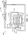
- Figs. 1-4 provide schematic embodiments of a thermal management system 1000.
- the system 1000 includes a pump, compressor, or other fluid flow mechanism 1100.
- the fluid flow mechanism 1100 has an electric machine 1110 configured to drive a flow device 1120.
- a driveshaft 1113 operably couples the flow device 1120 to the electric machine 1110 to drive the flow device 1120 to generate a desired flow of heat transfer fluid through a first heat exchange circuit 1101 and a second heat exchange circuit 1102.
- a conduit 1115 is extended through the fluid flow mechanism 1100 to allow for a heat transfer fluid to flow therethrough in thermal communication.
- a housing 1130 surrounds the fluid flow mechanism 1100.
- the conduit 1115 is extended through one or more pathways extended through the electric machine 1110 to provide thermal communication between the heat transfer fluid and components of the electric machine 1110 (e.g., rotors, stators, casings, etc.).
- the conduit 1115 is extended through the housing 1130 or between the housing 11130 and the electric machine 1110.
- the housing 1130, the first heat exchange circuit 1101, and the second heat exchange circuit 1102 are hermetically sealed to contain the heat transfer fluid therewithin.
- the flow device 1120 include an impeller having blades within the housing 1130 configured to generate a pressurized flow of the heat transfer fluid through the heat exchange circuits 1101, 1102.
- the first heat exchange circuit 1101 and the second heat exchange circuit 1102 are substantially thermally isolated from one another. Thermal isolation includes each heat exchange circuit 1101, 1102 configured to contain and flow the heat transfer fluid through the respective circuits. Changes in thermal load or temperature of the heat transfer fluid at the first heat exchange circuit 1101 in thermal communication with a first heat exchanger 1140 is substantially separate or isolated from changes in thermal load or temperature of the heat transfer fluid at the second heat exchange circuit 1102 in thermal communication with the fluid flow mechanism 1100 and the second heat exchanger 1150.
- the first heat exchange circuit 1101 is in substantially parallel flow arrangement with the second heat exchange circuit 1102.
- the second heat exchange circuit 1102 is in fluid communication with the conduit 1115 through the fluid flow mechanism 1100.
- the first heat exchange circuit 1101 is configured as a primary thermal transport bus (TTB).
- TTB is a device for transporting thermal energy from a physical location or system to another physical location or system using a thermal transport fluid flowing through a conduit extending between these physical locations and/or systems.
- the system 1000 is in closed-loop flow arrangement from an inlet 1108 of the flow device 1120 to an outlet 1104 of the flow device 1120.
- the first heat exchange circuit 1101 is configured in thermal communication with one or more first heat exchangers 1140. More specifically, for the exemplary embodiment shown, the one or more first heat exchangers 1140 includes a plurality of first heat exchangers 1140. More specifically, still, for the embodiment shown, the plurality of first heat exchangers 1140 includes one or more thermal load heat exchangers 1142 and one or more thermal bus heat exchangers 1144. In such a manner, it will be appreciated that the one or more first heat exchangers 1140, and in particular for the embodiment shown, the one or more thermal load heat exchangers 1142 and thermal bus heat exchangers 1144, are configured to receive or provide heat or thermal energy to the heat transfer fluid through the first heat exchange circuit 1101.
- the one or more thermal load heat exchangers 1142 are configured to reject heat or thermal energy from the heat transfer fluid through the first heat exchange circuit 1101, and the one or more thermal bus heat exchangers 1144 are configured to provide heat or thermal energy to the heat transfer fluid through the first heat exchange circuit 1101.
- the thermal load heat exchangers 1142 are positioned upstream of the thermal bus heat exchangers 1144 along the first heat exchange circuit 1101.
- the thermal load heat exchangers 1142 and the thermal bus heat exchangers 1144 may be positioned in any desired or operable configuration based on desired heat retention or heat release thereto.
- various embodiments may include any desired quantity of thermal bus heat exchangers 1142 or thermal load heat exchangers 1144 as may be applicable to removing or providing thermal energy in accordance with aspects of the present disclosure.
- the second heat exchange circuit 1102 is configured as a secondary TTB configured in thermal communication with one or more of a second heat exchanger 1150.
- the second heat exchanger 1150 is configured to receive heat or thermal energy from the heat transfer fluid through the second heat exchange circuit 1102.
- the second heat exchanger 1150 is an electric machine-cooler heat exchanger configured to remove heat or thermal energy from the heat transfer fluid through the second heat exchange circuit, such as to provide cooling or thermal attenuation to the fluid flow mechanism 1100, or particularly the electric machine 1110 through which the one or more conduits 1115 is extended in thermal communication thereto.
- the second heat exchange circuit 1102 is in closed-loop flow arrangement with the conduit 1115 through the fluid flow mechanism 1100.
- the flow device 1120 is configured to receive and induce, pressurize, or compress the flow of heat transfer fluid across the flow device 1120 from the suction side or inlet 1108 to the pressure side or outlet 1104.
- the thermal bus heat exchangers 1144 may extract or receive heat or thermal energy from the heat transfer fluid.
- the thermal load heat exchangers 1142 may then provide heat or thermal energy to the heat transfer fluid as the fluid flows in a loop back to the inlet 1108 of the flow device 1120.
- the thermal bus heat exchanger 1144 at a lubrication system, a fuel system, an air system, a hydraulic system, or combinations thereof.
- the various systems may be any one or more systems such as may be included with a propulsion system (e.g., propulsion system 10 in Fig. 5 ), an auxiliary power unit, a hybrid-electric power system, a fan propulsion system, or an aircraft in general (e.g., vehicle 100 in Fig. 5 ).
- the thermal bus heat exchanger 1144 receives heat or thermal energy from the heat transfer fluid and transfers the heat or thermal energy to a lubricant, a liquid and/or gaseous fuel, air or oxidizer generally, or a hydraulic fluid.
- the heat or thermal energy may be expelled, such as with a flow of air into atmospheric condition, or the thermal energy may be utilized to condition a flow of lubricant, fuel, air, or hydraulic fluid to a desired physical property (e.g., temperature, viscosity, or other desired physical property of fluid).
- a desired physical property e.g., temperature, viscosity, or other desired physical property of fluid.
- Various embodiments of the thermal load heat exchanger 1142 include any one or more systems that may provide or transmit heat or thermal energy to the heat transfer fluid at the system 1000. Exemplary embodiments of the thermal load heat exchanger 1142 are provided further below.
- the first heat exchange circuit 1101 forming a primary TTB may be configured to maintain or control the temperature of a first portion of heat transfer fluid in thermal communication with the first heat exchanger 1140 separately from the second heat exchange circuit 1102 forming a thermally isolated circuit sharing the same heat transfer fluid as the first heat exchange circuit 1101.
- the temperature and mass flow rate of the heat transfer fluid through the second heat exchange circuit 1102 allows for desired cooling or thermal attenuation at the electric machine 1110 substantially independent of the primary TTB flow through the first heat exchange circuit 1101.
- a first portion 1105 of the second heat exchange circuit 1102 is extended from upstream of the second heat exchanger 1150 to provide the heat transfer fluid from the fluid flow mechanism 1100 to thermal communication with the second heat exchanger 1150 to remove heat or thermal energy from the heat transfer fluid.
- the first portion 1105 is extended from the outlet 1104 of the flow device 1120.
- a second portion 1106 of the second heat exchange circuit 1102 is extended from downstream of the conduit 1115, or downstream of the electric machine 1110, to the inlet 1108 of the flow device 1120.
- a seal 1125 at least partially separates the flow device 1120 from the electric machine 1110, such as to thermally separate the first heat exchange circuit 1101 from the second heat exchange circuit 1102.
- the second heat exchange circuit 1102 is in an open charging relationship with the first heat exchange circuit 1101.
- the open charging relationship allows for fluid communication between the first heat exchange circuit 1101 and the second heat exchange circuit 1102.
- the open charging relationship may allow for the first heat exchange circuit 1101 to form an expansion tank or reservoir for the second heat exchange circuit 1102.
- Pressure changes at the second heat exchange circuit 1102 may be accommodated by the open charging relationship with the first heat exchange circuit 1101.
- the open charging relationship may mitigate over-pressurization at the system 1000, or undesired changes or fluctuations in pressure of the heat transfer fluid in the system 1000.
- a single flow device 1120 forming a single stage impeller may provide flow and pressure for the first portion of heat transfer fluid to flow through the first heat exchange circuit 1101 and for the second portion of heat transfer fluid to flow through the second heat exchange circuit 1102.
- the seal 1125 may include any appropriate type of filler material between the driveshaft 1113 and the surrounding housing, conduits, circuits, or other walls or surfaces. Exemplary seals include rotary seals, labyrinth seals, shaft sleeves, V-seals, lip seals, or other appropriate seals for rotating-to-static interfaces.
- the seal 1125 may allow for desired levels of leakage or fluid communication thereacross. However, it should be appreciated that leakages or fluid communication across the seal 1125 may occur while allowing for the first heat exchange circuit 1101 to be substantially thermally isolated, separate, parallel flow from the second heat exchange circuit 1102.
- the flow device 1120 at the fluid flow mechanism 1100 may include a first flow device 1121 and a second flow device 1122.
- the first flow device 1121 is configured to provide a first portion of the heat transfer fluid to the first heat exchange circuit 1101.
- the second flow device 1122 is configured to provide a second portion of the heat transfer fluid to the second heat exchange circuit 1102.
- the seal 1125 is positioned between the first flow device 1121 and the second flow device 1122, such as to thermally isolate the heat exchange circuits 1101, 1102 from one another.
- the first flow device 1121 and the second flow device 1122 provide respective flows of the first portion and the second portion of heat transfer fluid through the first heat exchange circuit 1101 and the second heat exchange circuit 1102, respectively.
- the first flow device 1121 is configured as a compressor, a pump, or other device to pressurize the flow of fluid.
- the second flow device 1122 is configured as a pump inducer. The second flow device 1122 configured as a pump inducer may act to raise the pressure of the heat transfer fluid.
- the first flow device 1121 flows the heat transfer fluid through the first heat exchange circuit 1101 such as described above.
- the second flow device 1122 is configured to receive and pressurize the flow of heat transfer fluid across the second flow device 1122 from a suction side proximate to the electric machine 1110 to the first portion 1105 of the second heat exchange circuit 1102.
- the second heat exchanger 1150 such as an electric machine-cooler heat exchanger, may extract or receive heat or thermal energy from the heat transfer fluid.
- the cooled heat transfer fluid then flows in a loop through the conduit 1115 and to the suction side of the second flow device 1122.
- a charging port 1107 fluidly connects the first heat exchange circuit 1101 upstream of the first heat exchanger 1140 and downstream of the first flow device 1121 to the first portion 1105 of the second heat exchange circuit 1102 upstream of the second heat exchanger 1150.
- the charging port 1107 allows the flow of heat transfer fluid to be re-charged at the second heat exchange circuit 1102. Additionally, or alternatively, the charging port 1107 sets a reference pressure for the second heat exchanger circuit 1102.
- the energy conversion system 2000 includes the fluid flow mechanism 1100, the first heat exchange circuit 1101, and the second heat exchange circuit 1102 such as described substantially in regard to the embodiments provided in Figs. 1-3 .
- the energy conversion system 2000 includes the thermal management system 1000 as a part of a turbomachine for a bottoming Rankine cycle.
- the energy conversion system 2000 may include at the first heat exchange circuit 1101 a recuperator or heat addition system 2100.
- the heat addition system 2100 may form a particular embodiment of the first heat exchanger 1140 described in regard to Figs. 1-3 .
- the recuperator 2100 is a waste heat recovery system, such as positioned at an exhaust of a combustion system, a turbine system, or a closed cycle engine system.
- the recuperator 2100 is configured to provide heat or thermal energy to the heat transfer fluid at the first heat exchange circuit 1101.
- the fluid flow mechanism 1100 includes a third flow device 1123 operably coupled to the driveshaft 1113.
- a first portion 1101a of the first heat exchange circuit 1101 extends from the first flow device 1121 in thermal communication with the recuperator 2100 then to the third flow device 1123.
- the third flow device 1123 is a turbine or expander configured to allow the flow of heat transfer fluid to expand through a second portion 1101b of the first heat exchange circuit 1101.
- One or more additional first heat exchangers 1140 such as a fluid heater 2200, is positioned in thermal communication with the second portion 1101b of the first heat exchange circuit 1101 downstream of the third flow device 1123 along the second portion 1101b of the first heat exchange circuit 1101.
- the fluid heater 2200 is configured to receive heat or thermal energy from the heat transfer fluid at the second portion 1101b of the first heat exchange circuit 1101.
- the energy conversion system 2000 further includes a third heat exchange circuit 1103.
- the third heat exchange circuit 1103 includes a first portion 1103a extended from the downstream or pressure side of the third flow device 1123 to provide the flow of heat transfer fluid to the second heat exchange circuit 1102 upstream of the second heat exchanger 1150.
- the third heat exchange circuit 1103 further includes a second portion 1103b extended from the second flow device 1122 to the third flow device 1123 and the conduit 1115 at the electric machine 1110.
- the second flow device 1122 is positioned along the driveshaft 1113 between the first flow device 1121 and the third flow device 1123.
- the electric machine 1110 is positioned between the first flow device 1121 and the second flow device 1122.
- the second flow device 1122 is positioned between the first flow device 1121 and the electric machine 1110. It should be appreciated that the second flow device 1122 may be positioned such as depicted in Figs. 2-4 .
- the first flow device 1121 and the third flow device 1123 may be re-arranged, such as may be suitable based on the configuration of the electric machine 1110 and heat exchangers.
- Various embodiments depicted and described herein include positions and flow arrangements of the heat exchange circuits such as to provide one or more improvement described herein.
- the energy conversion system 2000 depicted in Fig. 4 may include a hermetically sealed turbomachine formed by the fluid flow mechanism 1100 for a bottoming Rankine Cycle.
- the system 2000 is cooled with an internal and substantially independently temperature controlled second heat exchange circuit 1102 charged by the first heat exchange circuit 1101.
- the independent temperature control is allowed by the thermal isolation of the first heat exchange circuit 1101 and the second heat exchange circuit 1102, such as described above.
- the internal second heat exchange circuit 1102 is pumped with a hermetically sealed fluid flow mechanism 1100 such as described herein.
- the first, second, and third heat exchange circuits 1101, 1102, 1103 may be joined with the housing 1130 of the fluid flow mechanism to hermetically seal the heat transfer fluid therewithin.
- the driveshaft 1113 drives the flow devices 1121, 1122, 1123 to provide motive flow for cooling the electric machine 1110. Furthermore, the driveshaft 1113 drives the flow devices 1121, 1122, 1123 to provide motive flow for cooling the third flow device 1123 forming a power turbine.
- the second portion 1101b of the first heat exchange circuit 1101 may further include the fluid heater 2200 configured as a cooling heat exchanger (e.g., the thermal load heat exchanger 1142).
- the fluid heater 2200 receives heat or thermal energy from the heat transfer fluid at the second portion 1101b of the first heat exchange circuit to heat an oxidizer, such as air or oxygen (O 2 ), a liquid and/or gaseous fuel (e.g., a kerosene-based fuel, diesel fuel, natural gas, a hydrocarbon fuel generally, or other appropriate fuel, or combinations thereof), a lubricant (e.g., oil or oil-based lubricant, a synthetic lubricant, etc.), a hydraulic fluid, a refrigerant, or other desired fluid.
- an oxidizer such as air or oxygen (O 2 )
- a liquid and/or gaseous fuel e.g., a kerosene-based fuel, diesel fuel, natural gas, a hydrocarbon fuel generally, or other appropriate fuel, or combinations thereof
- a lubricant e.g., oil or oil-based lubricant, a synthetic lubricant, etc.
- a hydraulic fluid e.
- the heat transfer fluid provided herein may be supercritical fluid (SCF) generally, such as any desired fluid within the system 1000 at a temperature and pressure above its critical point.
- the heat transfer fluid is supercritical carbon dioxide.
- the heat transfer fluid is an SCF that is water, methane, ethane, propane, ethylene, propylene, methanol, ethanol, acetone, or nitrous oxide, or other appropriate fluid, or combinations thereof.
- the heat transfer fluid is any appropriate fluid for receiving and transferring heat or thermal energy within the system 1000 such as described herein.
- the vehicle 100 is an aircraft including an aircraft structure or airframe 105.
- the airframe 105 includes a fuselage 110 to which wings 120 and an empennage 130 are attached.
- the propulsion system 10 is attached to one or more portions of the airframe 105.
- the thermal management system 1000 is a system configured to desirably distribute thermal loads, such as to add or remove heat from one or more fluids or structures, such as, but not limited to, oxidizer at the propulsion system, fuel, lubricant, hydraulic fluid, pneumatic fluid, or cooling fluid for an electric machine, electronics, computing system, environmental control system, gear assembly, or other system or structure.
- thermal loads such as to add or remove heat from one or more fluids or structures, such as, but not limited to, oxidizer at the propulsion system, fuel, lubricant, hydraulic fluid, pneumatic fluid, or cooling fluid for an electric machine, electronics, computing system, environmental control system, gear assembly, or other system or structure.
- the propulsion system 10 is attached to an aft portion of the fuselage 110. In certain other instances, the propulsion system 10 is attached underneath, above, or through the wing 120 and/or portion of the empennage 130. In various embodiments, the propulsion system 10 is attached to the airframe 105 via a pylon or other mounting structure. In still other embodiments, the propulsion system 10 is housed within the airframe, such as may be exemplified in certain supersonic military or commercial aircraft.
- the vehicle 100 include a computing system 140, such as avionics or other electronics or computing devices configured to control the vehicle 100 or the propulsion system 10.
- the vehicle 100 may further include an environmental control system (ECS) 150, such as to provide thermally conditioned air to a cabin of the vehicle, the computing system 140, a vehicle surface or propulsion system anti-icing system 160, or other system of the vehicle 100 or propulsion system 10.
- ECS environmental control system
- the computing system 140 controls the electric machine or one or more heat exchangers of the thermal management system 1000 or energy conversion system 2000 to adjust one or more flow rates, pressures, heat transfer rates, temperatures, or other actuatable properties to provide thermally conditioned heat transfer fluid to one or more of the systems described herein.
- one or more of the first heat exchangers 1140 positioned in thermal communication along the first heat exchange circuit 1101 include a cooling system for the computing system 140, a heating system for the anti-icing system 160, a cooling or heating system for the ECS 150, or one or more heat exchangers for a liquid and/or gaseous fuel, compressor bleed air, lubricant system, bearing system, electric machine, or other system.
- the thermal load heat exchanger 1142 may include a cooled-cooling air system, such as a heat removal system for removing heat from compressor bleed air from the propulsion system.
- the thermal load heat exchangers 1142 may include engine controls (e.g., FADEC, digital engine controls, propeller controls, or other computing devices), electric machines, motor/generators, starters, batteries, alternators, capacitors, or other heat loads generated by the propulsion system.
- the thermal load heat exchangers 1142 may include avionics, ECS, or other heat loads generated by the vehicle 100.
- One or more components of the propulsion system 10 and thermal management system 1000 described herein may be manufactured or formed using any suitable process, such as an additive manufacturing process, such as a 3-D printing process.
- an additive manufacturing process such as a 3-D printing process.
- the use of such a process may allow such components to be formed integrally, as a single monolithic component, or as any suitable number of subcomponents, or at scales and intricacies not previously allowed or conceived in the art.
- the additive manufacturing process may allow such component to be integrally formed and include a variety of features not possible when using prior manufacturing methods.
- the additive manufacturing methods described herein may allow for the manufacture of the fluid flow mechanism as a single, integral component having the conduits and circuits as provided herein.
- the additive manufacturing methods described herein allow for the manufacture of the system 1000 having the fluid flow mechanism, the circuits, conduits, and housing hermetically sealing the heat transfer fluid such as described herein. Additionally, additive manufacturing allows for having unique features, configurations, thicknesses, materials, densities, fluid circuits and conduits, headers, seals, and other structures that may not have been possible or practical using prior manufacturing methods.
- Suitable additive manufacturing techniques in accordance with the present disclosure include, for example, Fused Deposition Modeling (FDM), Selective Laser Sintering (SLS), 3D printing such as by inkjets, laser jets, and binder jets, Stereolithography (SLA), Direct Selective Laser Sintering (DSLS), Electron Beam Sintering (EBS), Electron Beam Melting (EBM), Laser Engineered Net Shaping (LENS), Laser Net Shape Manufacturing (LNSM), Direct Metal Deposition (DMD), Digital Light Processing (DLP), Direct Selective Laser Melting (DSLM), Selective Laser Melting (SLM), Direct Metal Laser Melting (DMLM), and other known processes.
- FDM Fused Deposition Modeling
- SLS Selective Laser Sintering
- 3D printing such as by inkjets, laser jets, and binder jets
- SLA Stereolithography
- DSLS Direct Selective Laser Sintering
- EBS Electron Beam Sintering
- EBM Electron Beam Melting
- LENS Laser Engineere
- Suitable powder materials for the manufacture of the structures provided herein as integral, unitary, structures, or at scales and intricacies provided herein include metallic alloy, polymer, or ceramic powders.
- Exemplary metallic powder materials are stainless steel alloys, cobalt-chrome, aluminum alloys, titanium alloys, nickel based superalloys, and cobalt based superalloys.
- suitable alloys may include those that have been engineered to have good oxidation resistance, known as "superalloys" which have acceptable strength at the elevated temperatures of operation in a gas turbine engine, e.g.
- Hastelloy, Inconel alloys e.g., IN 738, IN 792, IN 939
- Rene alloys e.g., Rene N4, Rene N5, Rene 80, Rene 142, Rene 195
- Haynes alloys Mar M, CM 247, CM 247 LC, C263, 718, X-850, ECY 768, 282, X45, PWA 1483 and CMSX (e.g. CMSX-4) single crystal alloys.
- the manufactured objects of the present disclosure may be formed with one or more selected crystalline microstructures, such as directionally solidified (“DS") or single-crystal ("SX").
- DS directionally solidified
- SX single-crystal
Landscapes
- Engineering & Computer Science (AREA)
- Power Engineering (AREA)
- Mechanical Engineering (AREA)
- General Engineering & Computer Science (AREA)
- Chemical & Material Sciences (AREA)
- Combustion & Propulsion (AREA)
- Physics & Mathematics (AREA)
- Thermal Sciences (AREA)
- Health & Medical Sciences (AREA)
- General Health & Medical Sciences (AREA)
- Pulmonology (AREA)
- Aviation & Aerospace Engineering (AREA)
- Heat-Exchange Devices With Radiators And Conduit Assemblies (AREA)
- Engine Equipment That Uses Special Cycles (AREA)
Abstract
Description
- The present subject matter relates generally to heat exchange systems, thermal transport buses, and thermal attenuation structures.
- Thermal transport buses and heat exchange systems generally rely on high temperature motors and insulation systems for effective cooling of components of thermal management systems. However, such systems may leak or otherwise undesirably allow lubricants, fuels, or other fluids into the heat transfer fluid. Shaft seals, magnetic couplings, and high-temperature motor designs generate risks associated with leakages, including motor deterioration and loss of thermal efficiency. As such, there is a need for systems that mitigate or eliminate risks associated with shaft seals, magnetic couplings, and high-temperature motor design.
- Aspects and advantages of the invention will be set forth in part in the following description, or may be obvious from the description, or may be learned through practice of the invention.
- A thermal management system including a fluid flow mechanism. The fluid flow mechanism includes an electric machine. A conduit is formed through the electric machine allowing a heat transfer fluid to flow therethrough. The fluid flow mechanism includes a flow device configured to provide a first portion of the heat transfer fluid to a first heat exchange circuit and a second portion of heat transfer fluid to a second heat exchange circuit. The conduit is in fluid communication with the second heat exchange circuit.
- These and other features, aspects and advantages of the present invention will become better understood with reference to the following description and appended claims. The accompanying drawings, which are incorporated in and constitute a part of this specification, illustrate embodiments of the invention and, together with the description, serve to explain the principles of the invention.
- A full and enabling disclosure of the present invention, including the best mode thereof, directed to one of ordinary skill in the art, is set forth in the specification, which makes reference to the appended figures, in which:
-
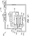
Figs. 1-3 are schematic embodiments of a thermal management system in accordance with aspects of the present disclosure; -
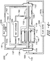
Fig. 4 is a schematic embodiment of an energy conversion system including an embodiment of the thermal management system in accordance with aspects of the present disclosure; and -
Fig. 5 is a perspective view of an exemplary vehicle including the thermal management system in accordance with aspects of the present disclosure. - Repeat use of reference characters in the present specification and drawings is intended to represent the same or analogous features or elements of the present invention.
- Reference now will be made in detail to embodiments of the invention, one or more examples of which are illustrated in the drawings. Each example is provided by way of explanation of the invention, not limitation of the invention. In fact, it will be apparent to those skilled in the art that various modifications and variations can be made in the present invention without departing from the scope or spirit of the invention. For instance, features illustrated or described as part of one embodiment can be used with another embodiment to yield a still further embodiment. Thus, it is intended that the present invention covers such modifications and variations as come within the scope of the appended claims and their equivalents.
- As used herein, the terms "first", "second", and "third" may be used interchangeably to distinguish one component from another and are not intended to signify location or importance of the individual components.
- The terms "upstream" and "downstream" refer to the relative direction with respect to fluid flow in a fluid pathway. For example, "upstream" refers to the direction from which the fluid flows, and "downstream" refers to the direction to which the fluid flows.
- Embodiments of a thermal management system are provided herein that may mitigate or eliminate risks associated with shaft seals, magnetic couplings, and high-temperature motor and/or generator design. The thermal management system may include a thermal transport bus (TTB) having a first heat exchanger along a first heat exchanger circuit utilizing the same heat transfer working fluid for cooling an electric machine through a temperature-controlled bleed circuit at a second heat exchange circuit. Embodiments provided allow for a single, closed-loop and hermetically-sealed system for the TTB. Such embodiments further allow for mitigating or eliminating risks associated with contamination of the TTB with lubricant, electric machine coolant, or other undesired fluids.
- Embodiments of the thermal management system include a dedicated secondary circuit, such as a second heat exchange circuit described below, thermally isolated from a primary TTB circuit along a first heat exchange circuit, and configured to maintain or control the temperature of heat transfer fluid through an electric machine, a pump, a compressor, or a fluid flow device generally. The thermally isolated secondary circuit shares the same fluid and pressure as the primary TTB circuit, such as through a seal configured to allow for desired fluid communication therethrough, or through an open charging circuit. The temperature and mass flow rate of the fluid through the thermally isolated secondary circuit allows for desired cooling, thermal attenuation, or heat transfer for the electric machine substantially independent of the primary TTB flow.
- Referring now to the drawings,
Figs. 1-4 provide schematic embodiments of athermal management system 1000. Thesystem 1000 includes a pump, compressor, or otherfluid flow mechanism 1100. Thefluid flow mechanism 1100 has anelectric machine 1110 configured to drive aflow device 1120. In certain embodiments, adriveshaft 1113 operably couples theflow device 1120 to theelectric machine 1110 to drive theflow device 1120 to generate a desired flow of heat transfer fluid through a firstheat exchange circuit 1101 and a secondheat exchange circuit 1102. Aconduit 1115 is extended through thefluid flow mechanism 1100 to allow for a heat transfer fluid to flow therethrough in thermal communication. Ahousing 1130 surrounds thefluid flow mechanism 1100. In a particular embodiment, theconduit 1115 is extended through one or more pathways extended through theelectric machine 1110 to provide thermal communication between the heat transfer fluid and components of the electric machine 1110 (e.g., rotors, stators, casings, etc.). In a still particular embodiment, theconduit 1115 is extended through thehousing 1130 or between the housing 11130 and theelectric machine 1110. In various embodiments, thehousing 1130, the firstheat exchange circuit 1101, and the secondheat exchange circuit 1102 are hermetically sealed to contain the heat transfer fluid therewithin. Various embodiments of theflow device 1120 include an impeller having blades within thehousing 1130 configured to generate a pressurized flow of the heat transfer fluid through theheat exchange circuits - The first
heat exchange circuit 1101 and the secondheat exchange circuit 1102 are substantially thermally isolated from one another. Thermal isolation includes eachheat exchange circuit heat exchange circuit 1101 in thermal communication with afirst heat exchanger 1140 is substantially separate or isolated from changes in thermal load or temperature of the heat transfer fluid at the secondheat exchange circuit 1102 in thermal communication with thefluid flow mechanism 1100 and thesecond heat exchanger 1150. In various embodiments, the firstheat exchange circuit 1101 is in substantially parallel flow arrangement with the secondheat exchange circuit 1102. The secondheat exchange circuit 1102 is in fluid communication with theconduit 1115 through thefluid flow mechanism 1100. - In certain embodiments, the first
heat exchange circuit 1101 is configured as a primary thermal transport bus (TTB). The primary TTB is a device for transporting thermal energy from a physical location or system to another physical location or system using a thermal transport fluid flowing through a conduit extending between these physical locations and/or systems. In particular embodiments, thesystem 1000 is in closed-loop flow arrangement from aninlet 1108 of theflow device 1120 to anoutlet 1104 of theflow device 1120. - In the embodiment shown, the first
heat exchange circuit 1101 is configured in thermal communication with one or morefirst heat exchangers 1140. More specifically, for the exemplary embodiment shown, the one or morefirst heat exchangers 1140 includes a plurality offirst heat exchangers 1140. More specifically, still, for the embodiment shown, the plurality offirst heat exchangers 1140 includes one or more thermalload heat exchangers 1142 and one or more thermalbus heat exchangers 1144. In such a manner, it will be appreciated that the one or morefirst heat exchangers 1140, and in particular for the embodiment shown, the one or more thermalload heat exchangers 1142 and thermalbus heat exchangers 1144, are configured to receive or provide heat or thermal energy to the heat transfer fluid through the firstheat exchange circuit 1101. - More specifically, in one embodiment, the one or more thermal
load heat exchangers 1142 are configured to reject heat or thermal energy from the heat transfer fluid through the firstheat exchange circuit 1101, and the one or more thermalbus heat exchangers 1144 are configured to provide heat or thermal energy to the heat transfer fluid through the firstheat exchange circuit 1101. In a particular embodiment, the thermalload heat exchangers 1142 are positioned upstream of the thermalbus heat exchangers 1144 along the firstheat exchange circuit 1101. However, it should be appreciated that in other embodiments the thermalload heat exchangers 1142 and the thermalbus heat exchangers 1144 may be positioned in any desired or operable configuration based on desired heat retention or heat release thereto. Furthermore, various embodiments may include any desired quantity of thermalbus heat exchangers 1142 or thermalload heat exchangers 1144 as may be applicable to removing or providing thermal energy in accordance with aspects of the present disclosure. - In still certain embodiments, the second
heat exchange circuit 1102 is configured as a secondary TTB configured in thermal communication with one or more of asecond heat exchanger 1150. In various embodiments, thesecond heat exchanger 1150 is configured to receive heat or thermal energy from the heat transfer fluid through the secondheat exchange circuit 1102. In a particular embodiment, thesecond heat exchanger 1150 is an electric machine-cooler heat exchanger configured to remove heat or thermal energy from the heat transfer fluid through the second heat exchange circuit, such as to provide cooling or thermal attenuation to thefluid flow mechanism 1100, or particularly theelectric machine 1110 through which the one ormore conduits 1115 is extended in thermal communication thereto. In still particular embodiments, such as depicted inFig. 2 , the secondheat exchange circuit 1102 is in closed-loop flow arrangement with theconduit 1115 through thefluid flow mechanism 1100. - During operation of the
system 1000, theflow device 1120 is configured to receive and induce, pressurize, or compress the flow of heat transfer fluid across theflow device 1120 from the suction side orinlet 1108 to the pressure side oroutlet 1104. The thermalbus heat exchangers 1144 may extract or receive heat or thermal energy from the heat transfer fluid. The thermalload heat exchangers 1142 may then provide heat or thermal energy to the heat transfer fluid as the fluid flows in a loop back to theinlet 1108 of theflow device 1120. In various embodiments, the thermalbus heat exchanger 1144 at a lubrication system, a fuel system, an air system, a hydraulic system, or combinations thereof. The various systems may be any one or more systems such as may be included with a propulsion system (e.g.,propulsion system 10 inFig. 5 ), an auxiliary power unit, a hybrid-electric power system, a fan propulsion system, or an aircraft in general (e.g.,vehicle 100 inFig. 5 ). In still certain embodiments, the thermalbus heat exchanger 1144 receives heat or thermal energy from the heat transfer fluid and transfers the heat or thermal energy to a lubricant, a liquid and/or gaseous fuel, air or oxidizer generally, or a hydraulic fluid. The heat or thermal energy may be expelled, such as with a flow of air into atmospheric condition, or the thermal energy may be utilized to condition a flow of lubricant, fuel, air, or hydraulic fluid to a desired physical property (e.g., temperature, viscosity, or other desired physical property of fluid). Various embodiments of the thermalload heat exchanger 1142 include any one or more systems that may provide or transmit heat or thermal energy to the heat transfer fluid at thesystem 1000. Exemplary embodiments of the thermalload heat exchanger 1142 are provided further below. - The first
heat exchange circuit 1101 forming a primary TTB may be configured to maintain or control the temperature of a first portion of heat transfer fluid in thermal communication with thefirst heat exchanger 1140 separately from the secondheat exchange circuit 1102 forming a thermally isolated circuit sharing the same heat transfer fluid as the firstheat exchange circuit 1101. The temperature and mass flow rate of the heat transfer fluid through the secondheat exchange circuit 1102 allows for desired cooling or thermal attenuation at theelectric machine 1110 substantially independent of the primary TTB flow through the firstheat exchange circuit 1101. - Referring now to
Fig. 1 , in a particular embodiment, afirst portion 1105 of the secondheat exchange circuit 1102 is extended from upstream of thesecond heat exchanger 1150 to provide the heat transfer fluid from thefluid flow mechanism 1100 to thermal communication with thesecond heat exchanger 1150 to remove heat or thermal energy from the heat transfer fluid. In one embodiment, such as depicted inFig. 1 , thefirst portion 1105 is extended from theoutlet 1104 of theflow device 1120. Asecond portion 1106 of the secondheat exchange circuit 1102 is extended from downstream of theconduit 1115, or downstream of theelectric machine 1110, to theinlet 1108 of theflow device 1120. Aseal 1125 at least partially separates theflow device 1120 from theelectric machine 1110, such as to thermally separate the firstheat exchange circuit 1101 from the secondheat exchange circuit 1102. In such configurations, the secondheat exchange circuit 1102 is in an open charging relationship with the firstheat exchange circuit 1101. The open charging relationship allows for fluid communication between the firstheat exchange circuit 1101 and the secondheat exchange circuit 1102. The open charging relationship may allow for the firstheat exchange circuit 1101 to form an expansion tank or reservoir for the secondheat exchange circuit 1102. Pressure changes at the secondheat exchange circuit 1102 may be accommodated by the open charging relationship with the firstheat exchange circuit 1101. As such, the open charging relationship may mitigate over-pressurization at thesystem 1000, or undesired changes or fluctuations in pressure of the heat transfer fluid in thesystem 1000. Asingle flow device 1120 forming a single stage impeller may provide flow and pressure for the first portion of heat transfer fluid to flow through the firstheat exchange circuit 1101 and for the second portion of heat transfer fluid to flow through the secondheat exchange circuit 1102. - The
seal 1125 may include any appropriate type of filler material between thedriveshaft 1113 and the surrounding housing, conduits, circuits, or other walls or surfaces. Exemplary seals include rotary seals, labyrinth seals, shaft sleeves, V-seals, lip seals, or other appropriate seals for rotating-to-static interfaces. Theseal 1125 may allow for desired levels of leakage or fluid communication thereacross. However, it should be appreciated that leakages or fluid communication across theseal 1125 may occur while allowing for the firstheat exchange circuit 1101 to be substantially thermally isolated, separate, parallel flow from the secondheat exchange circuit 1102. - Referring now to
Fig. 2 , in another exemplary embodiment, theflow device 1120 at thefluid flow mechanism 1100 may include afirst flow device 1121 and asecond flow device 1122. Thefirst flow device 1121 is configured to provide a first portion of the heat transfer fluid to the firstheat exchange circuit 1101. Thesecond flow device 1122 is configured to provide a second portion of the heat transfer fluid to the secondheat exchange circuit 1102. In a particular embodiment, theseal 1125 is positioned between thefirst flow device 1121 and thesecond flow device 1122, such as to thermally isolate theheat exchange circuits first flow device 1121 and thesecond flow device 1122 provide respective flows of the first portion and the second portion of heat transfer fluid through the firstheat exchange circuit 1101 and the secondheat exchange circuit 1102, respectively. - In a particular embodiment, the
first flow device 1121 is configured as a compressor, a pump, or other device to pressurize the flow of fluid. In another exemplary embodiment, thesecond flow device 1122 is configured as a pump inducer. Thesecond flow device 1122 configured as a pump inducer may act to raise the pressure of the heat transfer fluid. - During operation of the
system 1000, thefirst flow device 1121 flows the heat transfer fluid through the firstheat exchange circuit 1101 such as described above. Thesecond flow device 1122 is configured to receive and pressurize the flow of heat transfer fluid across thesecond flow device 1122 from a suction side proximate to theelectric machine 1110 to thefirst portion 1105 of the secondheat exchange circuit 1102. Thesecond heat exchanger 1150, such as an electric machine-cooler heat exchanger, may extract or receive heat or thermal energy from the heat transfer fluid. The cooled heat transfer fluid then flows in a loop through theconduit 1115 and to the suction side of thesecond flow device 1122. - Referring now to the exemplary embodiment of
Fig. 3 , the embodiment provided combines theflow devices Fig. 2 with an open charging relationship provided inFig. 1 . InFig. 3 , a chargingport 1107 fluidly connects the firstheat exchange circuit 1101 upstream of thefirst heat exchanger 1140 and downstream of thefirst flow device 1121 to thefirst portion 1105 of the secondheat exchange circuit 1102 upstream of thesecond heat exchanger 1150. The chargingport 1107 allows the flow of heat transfer fluid to be re-charged at the secondheat exchange circuit 1102. Additionally, or alternatively, the chargingport 1107 sets a reference pressure for the secondheat exchanger circuit 1102. - Referring now to
Fig. 4 , a schematic embodiment of anenergy conversion system 2000 including embodiments of thethermal management system 1000 described with regard toFigs. 1-3 is provided. Theenergy conversion system 2000 includes thefluid flow mechanism 1100, the firstheat exchange circuit 1101, and the secondheat exchange circuit 1102 such as described substantially in regard to the embodiments provided inFigs. 1-3 . InFig. 4 , theenergy conversion system 2000 includes thethermal management system 1000 as a part of a turbomachine for a bottoming Rankine cycle. - In a particular embodiment, the
energy conversion system 2000 may include at the firstheat exchange circuit 1101 a recuperator orheat addition system 2100. Theheat addition system 2100 may form a particular embodiment of thefirst heat exchanger 1140 described in regard toFigs. 1-3 . In various embodiments, therecuperator 2100 is a waste heat recovery system, such as positioned at an exhaust of a combustion system, a turbine system, or a closed cycle engine system. Therecuperator 2100 is configured to provide heat or thermal energy to the heat transfer fluid at the firstheat exchange circuit 1101. Thefluid flow mechanism 1100 includes athird flow device 1123 operably coupled to thedriveshaft 1113. Afirst portion 1101a of the firstheat exchange circuit 1101 extends from thefirst flow device 1121 in thermal communication with therecuperator 2100 then to thethird flow device 1123. - In a particular embodiment, the
third flow device 1123 is a turbine or expander configured to allow the flow of heat transfer fluid to expand through asecond portion 1101b of the firstheat exchange circuit 1101. One or more additionalfirst heat exchangers 1140, such as afluid heater 2200, is positioned in thermal communication with thesecond portion 1101b of the firstheat exchange circuit 1101 downstream of thethird flow device 1123 along thesecond portion 1101b of the firstheat exchange circuit 1101. Thefluid heater 2200 is configured to receive heat or thermal energy from the heat transfer fluid at thesecond portion 1101b of the firstheat exchange circuit 1101. - The
energy conversion system 2000 further includes a thirdheat exchange circuit 1103. The thirdheat exchange circuit 1103 includes afirst portion 1103a extended from the downstream or pressure side of thethird flow device 1123 to provide the flow of heat transfer fluid to the secondheat exchange circuit 1102 upstream of thesecond heat exchanger 1150. The thirdheat exchange circuit 1103 further includes asecond portion 1103b extended from thesecond flow device 1122 to thethird flow device 1123 and theconduit 1115 at theelectric machine 1110. - In
Fig. 4 thesecond flow device 1122 is positioned along thedriveshaft 1113 between thefirst flow device 1121 and thethird flow device 1123. Theelectric machine 1110 is positioned between thefirst flow device 1121 and thesecond flow device 1122. InFigs. 2-3 , thesecond flow device 1122 is positioned between thefirst flow device 1121 and theelectric machine 1110. It should be appreciated that thesecond flow device 1122 may be positioned such as depicted inFigs. 2-4 . Furthermore, it should be appreciated that thefirst flow device 1121 and thethird flow device 1123 may be re-arranged, such as may be suitable based on the configuration of theelectric machine 1110 and heat exchangers. Various embodiments depicted and described herein include positions and flow arrangements of the heat exchange circuits such as to provide one or more improvement described herein. - The
energy conversion system 2000 depicted inFig. 4 may include a hermetically sealed turbomachine formed by thefluid flow mechanism 1100 for a bottoming Rankine Cycle. Thesystem 2000 is cooled with an internal and substantially independently temperature controlled secondheat exchange circuit 1102 charged by the firstheat exchange circuit 1101. The independent temperature control is allowed by the thermal isolation of the firstheat exchange circuit 1101 and the secondheat exchange circuit 1102, such as described above. The internal secondheat exchange circuit 1102 is pumped with a hermetically sealedfluid flow mechanism 1100 such as described herein. As such, the first, second, and thirdheat exchange circuits housing 1130 of the fluid flow mechanism to hermetically seal the heat transfer fluid therewithin. Thedriveshaft 1113 drives theflow devices electric machine 1110. Furthermore, thedriveshaft 1113 drives theflow devices third flow device 1123 forming a power turbine. Thesecond portion 1101b of the firstheat exchange circuit 1101 may further include thefluid heater 2200 configured as a cooling heat exchanger (e.g., the thermal load heat exchanger 1142). Thefluid heater 2200 receives heat or thermal energy from the heat transfer fluid at thesecond portion 1101b of the first heat exchange circuit to heat an oxidizer, such as air or oxygen (O2), a liquid and/or gaseous fuel (e.g., a kerosene-based fuel, diesel fuel, natural gas, a hydrocarbon fuel generally, or other appropriate fuel, or combinations thereof), a lubricant (e.g., oil or oil-based lubricant, a synthetic lubricant, etc.), a hydraulic fluid, a refrigerant, or other desired fluid. - It should be appreciated that the heat transfer fluid provided herein may be supercritical fluid (SCF) generally, such as any desired fluid within the
system 1000 at a temperature and pressure above its critical point. In a particular embodiment, the heat transfer fluid is supercritical carbon dioxide. In other embodiments, the heat transfer fluid is an SCF that is water, methane, ethane, propane, ethylene, propylene, methanol, ethanol, acetone, or nitrous oxide, or other appropriate fluid, or combinations thereof. In still other embodiments, the heat transfer fluid is any appropriate fluid for receiving and transferring heat or thermal energy within thesystem 1000 such as described herein. - Referring now to
Fig. 5 , an exemplary embodiment of avehicle 100 including apropulsion system 10 and thethermal management system 1000 according to aspects of the present disclosure is provided. In an embodiment, thevehicle 100 is an aircraft including an aircraft structure orairframe 105. Theairframe 105 includes afuselage 110 to whichwings 120 and anempennage 130 are attached. Thepropulsion system 10 is attached to one or more portions of theairframe 105. In various embodiments, thethermal management system 1000 is a system configured to desirably distribute thermal loads, such as to add or remove heat from one or more fluids or structures, such as, but not limited to, oxidizer at the propulsion system, fuel, lubricant, hydraulic fluid, pneumatic fluid, or cooling fluid for an electric machine, electronics, computing system, environmental control system, gear assembly, or other system or structure. - In certain instances, the
propulsion system 10 is attached to an aft portion of thefuselage 110. In certain other instances, thepropulsion system 10 is attached underneath, above, or through thewing 120 and/or portion of theempennage 130. In various embodiments, thepropulsion system 10 is attached to theairframe 105 via a pylon or other mounting structure. In still other embodiments, thepropulsion system 10 is housed within the airframe, such as may be exemplified in certain supersonic military or commercial aircraft. - Various embodiments of the
vehicle 100 include acomputing system 140, such as avionics or other electronics or computing devices configured to control thevehicle 100 or thepropulsion system 10. Thevehicle 100 may further include an environmental control system (ECS) 150, such as to provide thermally conditioned air to a cabin of the vehicle, thecomputing system 140, a vehicle surface or propulsion systemanti-icing system 160, or other system of thevehicle 100 orpropulsion system 10. In various embodiments such as described herein, thecomputing system 140 controls the electric machine or one or more heat exchangers of thethermal management system 1000 orenergy conversion system 2000 to adjust one or more flow rates, pressures, heat transfer rates, temperatures, or other actuatable properties to provide thermally conditioned heat transfer fluid to one or more of the systems described herein. - In certain embodiments, one or more of the
first heat exchangers 1140 positioned in thermal communication along the firstheat exchange circuit 1101 include a cooling system for thecomputing system 140, a heating system for theanti-icing system 160, a cooling or heating system for theECS 150, or one or more heat exchangers for a liquid and/or gaseous fuel, compressor bleed air, lubricant system, bearing system, electric machine, or other system. The thermalload heat exchanger 1142 may include a cooled-cooling air system, such as a heat removal system for removing heat from compressor bleed air from the propulsion system. The thermalload heat exchangers 1142 may include engine controls (e.g., FADEC, digital engine controls, propeller controls, or other computing devices), electric machines, motor/generators, starters, batteries, alternators, capacitors, or other heat loads generated by the propulsion system. The thermalload heat exchangers 1142 may include avionics, ECS, or other heat loads generated by thevehicle 100. - One or more components of the
propulsion system 10 andthermal management system 1000 described herein may be manufactured or formed using any suitable process, such as an additive manufacturing process, such as a 3-D printing process. The use of such a process may allow such components to be formed integrally, as a single monolithic component, or as any suitable number of subcomponents, or at scales and intricacies not previously allowed or conceived in the art. In particular, the additive manufacturing process may allow such component to be integrally formed and include a variety of features not possible when using prior manufacturing methods. For example, the additive manufacturing methods described herein may allow for the manufacture of the fluid flow mechanism as a single, integral component having the conduits and circuits as provided herein. In further embodiments, the additive manufacturing methods described herein allow for the manufacture of thesystem 1000 having the fluid flow mechanism, the circuits, conduits, and housing hermetically sealing the heat transfer fluid such as described herein. Additionally, additive manufacturing allows for having unique features, configurations, thicknesses, materials, densities, fluid circuits and conduits, headers, seals, and other structures that may not have been possible or practical using prior manufacturing methods. - Suitable additive manufacturing techniques in accordance with the present disclosure include, for example, Fused Deposition Modeling (FDM), Selective Laser Sintering (SLS), 3D printing such as by inkjets, laser jets, and binder jets, Stereolithography (SLA), Direct Selective Laser Sintering (DSLS), Electron Beam Sintering (EBS), Electron Beam Melting (EBM), Laser Engineered Net Shaping (LENS), Laser Net Shape Manufacturing (LNSM), Direct Metal Deposition (DMD), Digital Light Processing (DLP), Direct Selective Laser Melting (DSLM), Selective Laser Melting (SLM), Direct Metal Laser Melting (DMLM), and other known processes. Suitable powder materials for the manufacture of the structures provided herein as integral, unitary, structures, or at scales and intricacies provided herein, include metallic alloy, polymer, or ceramic powders. Exemplary metallic powder materials are stainless steel alloys, cobalt-chrome, aluminum alloys, titanium alloys, nickel based superalloys, and cobalt based superalloys. In addition, suitable alloys may include those that have been engineered to have good oxidation resistance, known as "superalloys" which have acceptable strength at the elevated temperatures of operation in a gas turbine engine, e.g. Hastelloy, Inconel alloys (e.g., IN 738, IN 792, IN 939), Rene alloys (e.g., Rene N4, Rene N5, Rene 80, Rene 142, Rene 195), Haynes alloys, Mar M, CM 247, CM 247 LC, C263, 718, X-850, ECY 768, 282, X45, PWA 1483 and CMSX (e.g. CMSX-4) single crystal alloys. The manufactured objects of the present disclosure may be formed with one or more selected crystalline microstructures, such as directionally solidified ("DS") or single-crystal ("SX").
- This written description uses examples to disclose the invention, including the best mode, and also to enable any person skilled in the art to practice the invention, including making and using any devices or systems and performing any incorporated methods. The patentable scope of the invention is defined by the claims, and may include other examples that occur to those skilled in the art. Such other examples are intended to be within the scope of the claims if they include structural elements that do not differ from the literal language of the claims, or if they include equivalent structural elements with insubstantial differences from the literal languages of the claims.
- Further aspects of the invention are provided by the subject matter of the following clauses:
- 1. A thermal management system, the system comprising a fluid flow mechanism comprising an electric machine, wherein a conduit is formed through the electric machine allowing a heat transfer fluid to flow therethrough, wherein the fluid flow mechanism comprises a flow device configured to provide a first portion of the heat transfer fluid to a first heat exchange circuit and a second portion of heat transfer fluid to a second heat exchange circuit, wherein the conduit is in fluid communication with the second heat exchange circuit.
- 2. The system of any one or more clauses herein, wherein the second heat exchange circuit is at least partially in parallel flow arrangement with the first heat exchange circuit.
- 3. The system of any one or more clauses herein, wherein the fluid flow mechanism comprises a driveshaft operably coupled to the electric machine and the flow device.
- 4. The system of any one or more clauses herein, wherein the fluid flow mechanism comprises a housing, and wherein the housing, the electric machine, the first heat exchange circuit, and the second heat exchange circuit hermetically seal the heat transfer fluid therewithin.
- 5. The system of any one or more clauses herein, wherein the flow device comprises a first flow device configured to provide the first portion of the heat transfer fluid to the first heat exchange circuit, and wherein the flow device comprises a second flow device configured to provide the second portion of the heat transfer fluid to the second heat exchange circuit.
- 6. The system of any one or more clauses herein, wherein the fluid flow mechanism comprises a driveshaft operably coupled to the electric machine, the first flow device, and the second flow device.
- 7. The system of any one or more clauses herein, the fluid flow mechanism comprising a housing surrounding the driveshaft, the first flow device, and the second flow device, and wherein a seal is operably coupled to the driveshaft between the first flow device and the second flow device.
- 8. The system of any one or more clauses herein, wherein the seal separates the second heat exchange circuit and the first heat exchange circuit into substantially separate, parallel flows.
- 9. The system of any one or more clauses herein, wherein the flow device is an impeller.
- 10. The system of any one or more clauses herein, the system comprising a first heat exchanger positioned in thermal communication at the first heat exchange circuit.
- 11. The system of any one or more clauses herein, wherein a plurality of the first heat exchanger is positioned in thermal communication at the first heat exchange circuit.
- 12. The system of any one or more clauses herein, wherein the plurality of the first heat exchangers comprise a thermal bus heat exchanger and a thermal load heat exchanger each in thermal communication with the heat transfer fluid at the first heat exchange circuit.
- 13. The system of any one or more clauses herein, the system comprising a second heat exchanger positioned in thermal communication at the second heat exchange circuit.
- 14. The system of any one or more clauses herein, wherein the second heat exchanger is an electric machine-cooler heat exchanger positioned upstream of the conduit at the second heat exchange circuit.
- 15. A vehicle, the vehicle comprising a thermal management system, the system comprising a fluid flow mechanism, wherein the fluid flow mechanism comprises an electric machine, wherein a conduit is formed through the electric machine allowing a heat transfer fluid to flow therethrough, wherein the fluid flow mechanism comprises a flow device configured to provide a first portion of the heat transfer fluid to a first heat exchange circuit and a second portion of heat transfer fluid to a second heat exchange circuit, wherein the conduit is in fluid communication with the second heat exchange circuit; a thermal load heat exchanger positioned in thermal communication with the heat transfer fluid at the first heat exchange circuit, wherein the thermal load heat exchanger is configured to provide heat to the heat transfer fluid at the first heat exchange circuit; a thermal bus heat exchanger positioned in thermal communication with the heat transfer fluid at the first heat exchange circuit, wherein the thermal bus heat exchanger is configured to receive heat from the heat transfer fluid at the first heat exchange circuit; and an electric machine-cooler heat exchanger positioned in thermal communication with the heat transfer fluid at the second heat exchange circuit, wherein the electric machine-cooler heat exchanger is configured to receive heat from the heat transfer fluid at the second heat exchange circuit.
- 16. The vehicle of any one or more clauses herein, wherein the second heat exchange circuit is at least partially in parallel flow arrangement with the first heat exchange circuit.
- 17. The vehicle of any one or more clauses herein, wherein the flow device comprises a first flow device configured to provide the first portion of the heat transfer fluid to the second heat exchange circuit, and wherein the flow device comprises a second flow device configured to provide the second portion of the heat transfer fluid to the first heat exchange circuit.
- 18. The vehicle of any one or more clauses herein, wherein the thermal bus heat exchanger is positioned upstream of the thermal load heat exchanger along the first heat exchange circuit.
- 19. The vehicle of any one or more clauses herein, the thermal management system comprising a charging port fluidly connecting the first heat exchange circuit upstream of the thermal bus heat exchanger and downstream of the flow device to a first portion of the second heat exchange circuit upstream of the electric machine-cooler heat exchanger.
- 20. The vehicle of any one or more clauses herein, wherein the thermal load heat exchanger is one or more of a computing system, an anti-icing system, an electric machine, an environmental control system, or a propulsion system thermal load.
Claims (15)
- A thermal management system (1000), the system (1000) comprising:
a fluid flow mechanism (1100) comprising an electric machine (1110),
wherein a conduit (1115) is formed through the electric machine (1110) allowing a heat transfer fluid to flow therethrough, wherein the fluid flow mechanism (1100) comprises a flow device (1120) configured to provide a first portion of the heat transfer fluid to a first heat exchange circuit (1101) and a second portion of heat transfer fluid to a second heat exchange circuit (1102), wherein the conduit (1115) is in fluid communication with the second heat exchange circuit (1102). - The system (1000) of any preceding claim, wherein the second heat exchange circuit (1102) is at least partially in parallel flow arrangement with the first heat exchange circuit (1101).
- The system (1000) of any preceding claim, wherein the fluid flow mechanism (1100) comprises a driveshaft (1113) operably coupled to the electric machine (1110) and the flow device (1120).
- The system (1000) of any preceding claim, wherein the fluid flow mechanism (1100) comprises a housing (1130), and wherein the housing (1130), the electric machine (1110), the first heat exchange circuit (1101), and the second heat exchange circuit (1102) hermetically seal (1125) the heat transfer fluid therewithin.
- The system (1000) of any preceding claim, wherein the flow device (1120) comprises a first flow device (1120) configured to provide the first portion of the heat transfer fluid to the first heat exchange circuit (1101), and wherein the flow device (1120) comprises a second flow device (1120) configured to provide the second portion of the heat transfer fluid to the second heat exchange circuit (1102).
- The system (1000) of any preceding claim, wherein the fluid flow mechanism (1100) comprises a driveshaft (1113) operably coupled to the electric machine (1110), the first flow device (1120), and the second flow device (1120).
- The system (1000) of any preceding claim, the fluid flow mechanism (1100) comprising a housing (1130) surrounding the driveshaft (1113), the first flow device (1120), and the second flow device (1120), and wherein a seal (1125) is operably coupled to the driveshaft (1113) between the first flow device (1120) and the second flow device (1120).
- The system (1000) of any preceding claim, wherein the seal (1125) separates the second heat exchange circuit (1102) and the first heat exchange circuit (1101) into substantially separate, parallel flows.
- The system (1000) of any preceding claim, wherein the flow device (1120) is an impeller.
- The system (1000) of any preceding claim, the system comprising:
a first heat exchanger (1140) positioned in thermal communication at the first heat exchange circuit (1101). - The system (1000) of any preceding claim, wherein the first heat exchanger (1140) comprises a plurality of first heat exchangers (1140) positioned in thermal communication with the heat transfer fluid through the first heat exchange circuit (1101).
- The system (1000) of any preceding claim, wherein the plurality of first heat exchangers (1140) comprises a thermal bus heat exchanger (1142) and a thermal load heat exchanger (1144) each in thermal communication with the heat transfer fluid through the first heat exchange circuit (1101).
- The system (1000) of any preceding claim, the system comprising:
a second heat exchanger (1150) positioned in thermal communication at the second heat exchange circuit (1102). - The system (1000) of any preceding claim, wherein the second heat exchanger (1150) is an electric machine (1110)-cooler heat exchanger positioned upstream of the conduit (1115) at the second heat exchange circuit (1102).
- A vehicle, the vehicle comprising:a thermal management system (1000), the system comprising a fluid flow mechanism (1100), wherein the fluid flow mechanism (1100) comprises an electric machine (1110), wherein a conduit (1115) is formed through the electric machine (1110) allowing a heat transfer fluid to flow therethrough, wherein the fluid flow mechanism (1100) comprises a flow device (1120) configured to provide a first portion of the heat transfer fluid to a first heat exchange circuit (1101) and a second portion of heat transfer fluid to a second heat exchange circuit (1102), wherein the conduit (1115) is in fluid communication with the second heat exchange circuit (1102);a thermal load heat exchanger (1144) positioned in thermal communication with the heat transfer fluid at the first heat exchange circuit (1101), wherein the thermal load heat exchanger (1144) is configured to provide heat to the heat transfer fluid at the first heat exchange circuit (1101);a thermal bus heat exchanger (1142) positioned in thermal communication with the heat transfer fluid at the first heat exchange circuit (1101), wherein the thermal bus heat exchanger (1142) is configured to receive heat from the heat transfer fluid at the first heat exchange circuit (1101); andan electric machine (1110)-cooler heat exchanger positioned in thermal communication with the heat transfer fluid at the second heat exchange circuit (1102), wherein the electric machine (1110)-cooler heat exchanger is configured to receive heat from the heat transfer fluid at the second heat exchange circuit (1102).
Applications Claiming Priority (1)
| Application Number | Priority Date | Filing Date | Title |
|---|---|---|---|
| US17/319,802 US11863051B2 (en) | 2021-05-13 | 2021-05-13 | Thermal management system |
Publications (1)
| Publication Number | Publication Date |
|---|---|
| EP4089888A1 true EP4089888A1 (en) | 2022-11-16 |
Family
ID=81307358
Family Applications (1)
| Application Number | Title | Priority Date | Filing Date |
|---|---|---|---|
| EP22167922.8A Pending EP4089888A1 (en) | 2021-05-13 | 2022-04-12 | Thermal management system |
Country Status (3)
| Country | Link |
|---|---|
| US (1) | US11863051B2 (en) |
| EP (1) | EP4089888A1 (en) |
| CN (1) | CN115342665A (en) |
Families Citing this family (2)
| Publication number | Priority date | Publication date | Assignee | Title |
|---|---|---|---|---|
| ES3002634T3 (en) * | 2021-07-13 | 2025-03-07 | Airbus Operations Slu | Method for cooling an electrical aircraft propulsion system |
| US20240417080A1 (en) * | 2023-06-14 | 2024-12-19 | Pratt & Whitney Canada Corp. | Aircraft and associated method of conditioning cabin air |
Citations (3)
| Publication number | Priority date | Publication date | Assignee | Title |
|---|---|---|---|---|
| US20040261428A1 (en) * | 2003-06-24 | 2004-12-30 | Honeywell International Inc. | Cabin air compressor cooling system |
| JP3716061B2 (en) * | 1996-10-25 | 2005-11-16 | 三菱重工業株式会社 | Turbo refrigerator |
| EP3264571A2 (en) * | 2016-06-28 | 2018-01-03 | Trane International Inc. | Electric motor with harmonic energy shunting |
Family Cites Families (17)
| Publication number | Priority date | Publication date | Assignee | Title |
|---|---|---|---|---|
| US3189769A (en) | 1961-08-01 | 1965-06-15 | Gen Electric | Dynamoelectric machine rotor cooling |
| DE10314526B4 (en) | 2003-03-31 | 2007-11-29 | Geräte- und Pumpenbau GmbH Dr. Eugen Schmidt | Coolant pump, in particular flow-cooled electric coolant pump with integrated directional control valve |
| US7064463B2 (en) | 2004-07-20 | 2006-06-20 | Wavecrest Laboratories Llc | Dynamoelectric machine with embedded heat exchanger |
| US9006942B2 (en) | 2009-05-07 | 2015-04-14 | Hamilton Sundstrand Corporation | Generator main stator back-iron cooling sleeve |
| JP5260591B2 (en) | 2010-03-30 | 2013-08-14 | 株式会社日立製作所 | Permanent magnet rotating electrical machine and wind power generation system |
| SE534838C2 (en) | 2010-05-21 | 2012-01-17 | Bae Systems Haegglunds Ab | Electric motor cooling device |
| JP5290244B2 (en) | 2010-06-18 | 2013-09-18 | 株式会社小松製作所 | Electric motor for construction machine and cooling circuit for electric motor |
| US8529202B2 (en) * | 2010-10-12 | 2013-09-10 | General Electric Company | System and method for turbine compartment ventilation |
| US8604651B2 (en) | 2011-02-18 | 2013-12-10 | Hamilton Sundstrand Space Systems International, Inc. | Cooling of permanent magnet electric machine |
| US9689281B2 (en) | 2011-12-22 | 2017-06-27 | Nanjing Tica Air-Conditioning Co., Ltd. | Hermetic motor cooling for high temperature organic Rankine cycle system |
| US20130195695A1 (en) * | 2012-01-30 | 2013-08-01 | General Electric Company | Hollow rotor motor and systems comprising the same |
| EP2803855A1 (en) * | 2013-05-16 | 2014-11-19 | Siemens Aktiengesellschaft | Cooling system with two bridged cooling circuits, wind turbine with such a cooling system |
| EP3055563B1 (en) | 2013-10-11 | 2020-09-02 | Eaton Corporation | Electric motor driven pump |
| JP5924352B2 (en) | 2014-01-23 | 2016-05-25 | 株式会社デンソー | Rotating electric machine |
| EP3184336B1 (en) * | 2015-12-21 | 2021-05-12 | Toyota Jidosha Kabushiki Kaisha | Vehicle with a vehicular cooling system |
| US9580159B1 (en) | 2016-06-21 | 2017-02-28 | Brian Provost | Outboard-motor closed-loop cooler system apparatus |
| US11022037B2 (en) * | 2018-01-04 | 2021-06-01 | General Electric Company | Gas turbine engine thermal management system |
-
2021
- 2021-05-13 US US17/319,802 patent/US11863051B2/en active Active
-
2022
- 2022-04-12 EP EP22167922.8A patent/EP4089888A1/en active Pending
- 2022-05-11 CN CN202210509948.4A patent/CN115342665A/en active Pending
Patent Citations (3)
| Publication number | Priority date | Publication date | Assignee | Title |
|---|---|---|---|---|
| JP3716061B2 (en) * | 1996-10-25 | 2005-11-16 | 三菱重工業株式会社 | Turbo refrigerator |
| US20040261428A1 (en) * | 2003-06-24 | 2004-12-30 | Honeywell International Inc. | Cabin air compressor cooling system |
| EP3264571A2 (en) * | 2016-06-28 | 2018-01-03 | Trane International Inc. | Electric motor with harmonic energy shunting |
Also Published As
| Publication number | Publication date |
|---|---|
| US11863051B2 (en) | 2024-01-02 |
| CN115342665A (en) | 2022-11-15 |
| US20220368197A1 (en) | 2022-11-17 |
Similar Documents
| Publication | Publication Date | Title |
|---|---|---|
| CN114909219B (en) | Carrier with energy conversion system | |
| US11614037B2 (en) | Method and system for bleed flow power generation | |
| US11828227B2 (en) | Aircraft powerplant comprising a recuperative closed-cycle arrangement | |
| CN114790942B (en) | Embedded Motor | |
| US12173654B2 (en) | Fuel heater and energy conversion system | |
| US11859500B2 (en) | Gas turbine engine with a fluid conduit system and a method of operating the same | |
| EP2622192A2 (en) | Aircraft engine systems and methods for operating same | |
| US11788425B2 (en) | Gas turbine engine with clearance control system | |
| US20190203644A1 (en) | Thermal Management System | |
| US11863051B2 (en) | Thermal management system | |
| EP4367373B1 (en) | Turbine engines having hydrogen fuel systems | |
| EP4303416A1 (en) | Turbo expanders for turbine engines having hydrogen fuel systems | |
| US12258907B2 (en) | Vehicle and propulsion system with hydrogen fuel system | |
| US12305516B2 (en) | Gas turbine engine with a fluid conduit system and a method of operating the same | |
| EP4063631A2 (en) | Turbine engine system equipped with a fuel deoxygenation system and turboelectric power system | |
| US12503244B2 (en) | Thermal management system for aircraft propulsion system using a flow of compressed fluid extracted from a compressor section | |
| US20260036065A1 (en) | Passive thermal management systems and related methods | |
| CN117662260A (en) | Closed loop cooling system for gas turbine engines |
Legal Events
| Date | Code | Title | Description |
|---|---|---|---|
| PUAI | Public reference made under article 153(3) epc to a published international application that has entered the european phase |
Free format text: ORIGINAL CODE: 0009012 |
|
| STAA | Information on the status of an ep patent application or granted ep patent |
Free format text: STATUS: THE APPLICATION HAS BEEN PUBLISHED |
|
| AK | Designated contracting states |
Kind code of ref document: A1 Designated state(s): AL AT BE BG CH CY CZ DE DK EE ES FI FR GB GR HR HU IE IS IT LI LT LU LV MC MK MT NL NO PL PT RO RS SE SI SK SM TR |
|
| STAA | Information on the status of an ep patent application or granted ep patent |
Free format text: STATUS: REQUEST FOR EXAMINATION WAS MADE |
|
| 17P | Request for examination filed |
Effective date: 20230510 |
|
| RBV | Designated contracting states (corrected) |
Designated state(s): AL AT BE BG CH CY CZ DE DK EE ES FI FR GB GR HR HU IE IS IT LI LT LU LV MC MK MT NL NO PL PT RO RS SE SI SK SM TR |