EP4089847A2 - High voltage (hv) terminal frame - Google Patents
High voltage (hv) terminal frame Download PDFInfo
- Publication number
- EP4089847A2 EP4089847A2 EP22173082.3A EP22173082A EP4089847A2 EP 4089847 A2 EP4089847 A2 EP 4089847A2 EP 22173082 A EP22173082 A EP 22173082A EP 4089847 A2 EP4089847 A2 EP 4089847A2
- Authority
- EP
- European Patent Office
- Prior art keywords
- terminal
- spring
- assembly
- terminal frame
- bus bar
- Prior art date
- Legal status (The legal status is an assumption and is not a legal conclusion. Google has not performed a legal analysis and makes no representation as to the accuracy of the status listed.)
- Pending
Links
Images




Classifications
-
- H—ELECTRICITY
- H01—ELECTRIC ELEMENTS
- H01R—ELECTRICALLY-CONDUCTIVE CONNECTIONS; STRUCTURAL ASSOCIATIONS OF A PLURALITY OF MUTUALLY-INSULATED ELECTRICAL CONNECTING ELEMENTS; COUPLING DEVICES; CURRENT COLLECTORS
- H01R13/00—Details of coupling devices of the kinds covered by groups H01R12/70 or H01R24/00 - H01R33/00
- H01R13/02—Contact members
- H01R13/15—Pins, blades or sockets having separate spring member for producing or increasing contact pressure
- H01R13/187—Pins, blades or sockets having separate spring member for producing or increasing contact pressure with spring member in the socket
-
- H—ELECTRICITY
- H01—ELECTRIC ELEMENTS
- H01R—ELECTRICALLY-CONDUCTIVE CONNECTIONS; STRUCTURAL ASSOCIATIONS OF A PLURALITY OF MUTUALLY-INSULATED ELECTRICAL CONNECTING ELEMENTS; COUPLING DEVICES; CURRENT COLLECTORS
- H01R13/00—Details of coupling devices of the kinds covered by groups H01R12/70 or H01R24/00 - H01R33/00
- H01R13/02—Contact members
- H01R13/10—Sockets for co-operation with pins or blades
- H01R13/11—Resilient sockets
-
- H—ELECTRICITY
- H01—ELECTRIC ELEMENTS
- H01R—ELECTRICALLY-CONDUCTIVE CONNECTIONS; STRUCTURAL ASSOCIATIONS OF A PLURALITY OF MUTUALLY-INSULATED ELECTRICAL CONNECTING ELEMENTS; COUPLING DEVICES; CURRENT COLLECTORS
- H01R13/00—Details of coupling devices of the kinds covered by groups H01R12/70 or H01R24/00 - H01R33/00
- H01R13/02—Contact members
- H01R13/10—Sockets for co-operation with pins or blades
- H01R13/11—Resilient sockets
- H01R13/113—Resilient sockets co-operating with pins or blades having a rectangular transverse section
-
- H—ELECTRICITY
- H01—ELECTRIC ELEMENTS
- H01R—ELECTRICALLY-CONDUCTIVE CONNECTIONS; STRUCTURAL ASSOCIATIONS OF A PLURALITY OF MUTUALLY-INSULATED ELECTRICAL CONNECTING ELEMENTS; COUPLING DEVICES; CURRENT COLLECTORS
- H01R13/00—Details of coupling devices of the kinds covered by groups H01R12/70 or H01R24/00 - H01R33/00
- H01R13/40—Securing contact members in or to a base or case; Insulating of contact members
-
- H—ELECTRICITY
- H01—ELECTRIC ELEMENTS
- H01R—ELECTRICALLY-CONDUCTIVE CONNECTIONS; STRUCTURAL ASSOCIATIONS OF A PLURALITY OF MUTUALLY-INSULATED ELECTRICAL CONNECTING ELEMENTS; COUPLING DEVICES; CURRENT COLLECTORS
- H01R4/00—Electrically-conductive connections between two or more conductive members in direct contact, i.e. touching one another; Means for effecting or maintaining such contact; Electrically-conductive connections having two or more spaced connecting locations for conductors and using contact members penetrating insulation
- H01R4/28—Clamped connections, spring connections
- H01R4/48—Clamped connections, spring connections utilising a spring, clip, or other resilient member
- H01R4/4809—Clamped connections, spring connections utilising a spring, clip, or other resilient member using a leaf spring to bias the conductor toward the busbar
-
- H—ELECTRICITY
- H01—ELECTRIC ELEMENTS
- H01R—ELECTRICALLY-CONDUCTIVE CONNECTIONS; STRUCTURAL ASSOCIATIONS OF A PLURALITY OF MUTUALLY-INSULATED ELECTRICAL CONNECTING ELEMENTS; COUPLING DEVICES; CURRENT COLLECTORS
- H01R13/00—Details of coupling devices of the kinds covered by groups H01R12/70 or H01R24/00 - H01R33/00
- H01R13/02—Contact members
- H01R13/03—Contact members characterised by the material, e.g. plating, or coating materials
-
- H—ELECTRICITY
- H01—ELECTRIC ELEMENTS
- H01R—ELECTRICALLY-CONDUCTIVE CONNECTIONS; STRUCTURAL ASSOCIATIONS OF A PLURALITY OF MUTUALLY-INSULATED ELECTRICAL CONNECTING ELEMENTS; COUPLING DEVICES; CURRENT COLLECTORS
- H01R13/00—Details of coupling devices of the kinds covered by groups H01R12/70 or H01R24/00 - H01R33/00
- H01R13/40—Securing contact members in or to a base or case; Insulating of contact members
- H01R13/42—Securing in a demountable manner
Definitions
- the present disclosure is directed to a high voltage terminal frame and in particular to a two-piece high voltage terminal frame.
- High voltage terminal frames include a rigid outer housing and a more compliant contact spring.
- the rigid outer housing is separate from the more compliant contact spring, made of different materials, and requiring assembly at manufacture.
- This type of HV frame is a two-piece assembly.
- a conductive bus bar is crimped to the rigid outer housing, resulting in a three-piece assembly. It would be beneficial to develop a high voltage terminal frame that provides the same functionality but that does not require separate components for the rigid outer housing and the more compliant contact spring.
- a two-piece high voltage (HV) terminal frame includes a terminal frame and a contact spring.
- the terminal frame includes at least a top portion, a bottom portion, and a middle portion forming an opening for receiving a first bus bar and a second bus bar.
- the contact spring is configured to engage the top portion of the terminal frame, wherein the contact spring includes a spring portion that extends into the opening of the terminal frame.
- a header assembly includes a housing assembly, a two-piece terminal assembly, and a terminal position assurance (TPA).
- the housing assembly includes at least a first opening for receiving a bus bar.
- the two-piece terminal assembly includes a terminal frame and a contact spring engaged with the terminal frame, wherein the two-piece terminal assembly is positioned within the housing assembly.
- the terminal position assurance (TPA) positioned within the housing assembly adjacent to the two-piece terminal assembly.
- Figure 1A is an isometric view of a high voltage (HV) terminal assembly according to some embodiments
- Figure 1B is an isometric view of a high voltage (HV) terminal assembly with an outer covering removed illustrate a high voltage (HV) terminal frame according to some embodiments.
- Figure 2 is a cross-sectional view of a header assembly associated with the HV terminal assembly according to some embodiments.
- Figure 3A is an isometric view of a terminal assembly with installed spring contact according to some embodiments
- Figure 3B is a side view of the terminal assembly with installed spring contact according to some embodiments.
- Figure 4A is a cross-sectional view of a header assembly positioned to receive a header side bus bar according to some embodiments
- Figure 4B is a cross-sectional view of the header assembly that includes the header side bus bar in the installed position according to some embodiments.
- Figures 5A and 5B are isometric views of a bi-directional pass-thru terminal assembly according to some embodiments.
- Figure 6 is an exploded view of a bi-directional pass-thru header assembly that utilizes the bi-directional pass-thru terminal assembly shown in Figures 5A and 5B according to some embodiments.
- Figure 7 is an isometric view of a bi-directional pass-thru header assembly according to some embodiments.
- the present invention is directed to a high voltage (HV) terminal assembly.
- the HV terminal assembly is a two-part assembly that includes a terminal frame and a spring contact, wherein the spring contact is configured to engage with the terminal frame.
- the terminal frame is fabricated from a first piece of material (e.g., stainless steel) having a first thickness and the spring contact is fabricated form a second piece of material (e.g., stainless steel) having a second thickness less than the first thickness.
- a first piece of material e.g., stainless steel
- the spring contact is fabricated form a second piece of material (e.g., stainless steel) having a second thickness less than the first thickness.
- a HV terminal assembly 100 that utilizes a pair of header assemblies 108a, 108b.
- the HV terminal assembly 100 is a right-angle assembly.
- Terminal ports 102a, 102b are configured to receive a corresponding terminal (not shown) in a first longitudinal or horizontal direction.
- Conductive bus bars 104a, 104b (referred to as a connector side bus bar) extends in a vertical direction at a right-angle to the direction of connection associated with the terminal ports 102a, 102b.
- a portion of the housing associated with the HV terminal assembly 100 is removed to expose the header assemblies 108a, 108b.
- a connector side bus bar 106a, 106b extends longitudinally from the header assemblies 108a, 108b, respectively.
- the header side bus bars 104a, 104b extend in a downward direction from the header assemblies 108a, 108b.
- the header side bus bars 104a, 104b are pass through bus bars that do not require crimping of the bus bars to the header assemblies 108a, 108b, respective..
- the connector side bus bar 106a, 106b is slid downward into the header assemblies 108a, 108b, respectively, and is pressed into contact with the header side bus bars 104a, 104b, respectively, by contact springs (126, shown in Figures 3A and 3B ).
- each terminal assembly 114 is a two-piece assembly, including a terminal frame 116 and a contact spring 118, described in more detail with respect to Figures 3A and 3B .
- header assembly 108a includes a housing assembly 110a, terminal assembly 114a, and terminal position assurance (TPA) 112a.
- terminal assembly 114a is located within housing assembly 110a.
- header side bus bar 104a is positioned within housing assembly 110a and is retained by terminal assembly 114a.
- An opening or port 115a is configured to receive the connector side bus bar 106a (shown in Figure 1A ), which is retained in place by terminal assembly 114a.
- the contact spring 118 is configured to exert a normal force on the connector side bus bar 106a that urges the connector side bus bar 106a into contact with the header side bus bar 104a.
- TPA 112a is configured to be placed within the housing assembly 110a, which engages with terminal assembly 114a within housing assembly 110a.
- TPA 112a includes a lock feature (not shown) that engages with the housing assembly 110a to lock the TPA 112a into place within the housing assembly 110a.
- the header assembly 108b includes a housing assembly 110b, terminal assembly 114b, and terminal position assurance (TPA) 112b.
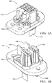
- Figures 3A and 3B illustrate the terminal assembly 114a, which is a two-piece assembly that includes terminal frame 116 and contact spring 118.
- Terminal assembly 114a includes an opening.
- the spring portion 126 of contact spring 118 extends into the opening, wherein the opening is configured to receive header side bus bar 104a and connector side bus bar 106a (as shown in Figures 1A and 1B ).
- the spring portion 126 of contact spring 118 is brought into contact with the connector side bus bar 106a and urges the connector side bus bar 106a into contact with the header side bus bar 104a (as shown in more detail in Figures 4A and 4B ).
- terminal frame 116 is fabricated from a single piece of material having a first uniform thickness folded into the desired shape.
- contact spring 118 is fabricated from a single piece of material having a second uniform thickness folded into a desired shape, wherein the second thickness is less than the first thickness.
- One benefit of a two-piece terminal assembly wherein the thickness of the material forming the terminal frame 116 is greater than the thickness of the material forming the contact spring 118 is the greater thickness of the terminal frame 116 provides improved rigidity as compared with the contact spring 118.
- the contact spring 118 - and in particular the spring portion 126 - is more flexible due to the thickness of the contact spring.
- the terminal frame 116 and the contact spring 118 are fabricated from the same material (e.g., stainless steel), wherein characteristics such as rigidity of the terminal frame 116 and the contact spring 118 are selected based on the thickness of the respective components.
- the terminal frame 116 and the contact spring 118 may be fabricated using different materials.
- the terminal frame 116 may be fabricated from a high carbon steel, wherein the contact spring 118 may be fabricated from stainless steel.
- the terminal frame 116 is "C-shaped" and includes a top portion 132, a middle portion 134, and a bottom portion 136, wherein the top portion 132 and the bottom portion 136 are parallel to one another.
- the middle portion 134 is transverse to the top portion 132 and the bottom portion 136 and connects the top portion 132 and the bottom portion 136.
- the top portion 132, the middle portion 134 and the bottom portion 136 form the opening configured to receive the connector side bus bar 106 and the header side bus bar 104.
- the top portion 132 is configured to receive and capture the contact spring 118, wherein the spring portion 126 extends into the opening and is configured to exert a normal force on the connector side bus bar 106 to urge the connector side bus bar 106 into contact with the header side bus bar 104.
- the bottom portion 136 of the terminal frame 116 includes a stop feature 142, a front guide feature 138 and a side guide feature 140.
- the stop feature 142 defines the maximum extent the header side bus bar 104 can extend into the terminal frame 116.
- the side guide feature 140 and the front guide feature 138 aid in guiding the header side bus bar 104 into the opening of the terminal frame 116.
- the front guide feature 138 interacts with an overlapping feature 150 (shown in Figures 4A and 4B ) of the TPA 112a to ensure the terminal frame 116 is properly positioned within the housing 110.
- contact spring 118 is also "C-shaped" having a first portion 120, a middle portion 122 and a second portion 124.
- the first portion 120 and the second portion 124 are configured to engage with the terminal frame 116, wherein the spring portion 126 extends into an opening provided within the terminal assembly 114a.
- the first portion 120 and the second portion 124 wrap around the top portion 132 of terminal frame 116, and prevent the contact spring 118 from moving forward or backward relative to the terminal frame 116.
- contact spring 118 also includes a cut-out portion 128 located within the middle portion 122 and a spring 130 formed within the cut-out portion 128.
- the spring 130 bends or flexes toward the terminal frame 116.
- the spring 130 bends or flexes against the top surface of the terminal frame 116.
- a groove or channel (not shown) formed on the top surface of the terminal frame 116 is configured to receive and capture the spring 130 when the contact spring 118 is fully engaged with the terminal frame 116. The engagement of the spring 130 with the groove or channel (not shown) of the terminal frame 116 prevents the contact spring 118 from sliding relative to the terminal frame 116.
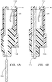
- FIGS 4A and 4B are cross-sectional views that illustrate insertion of a header side bus bar 104b into the header assembly 108b.
- the contact spring 118 is installed on the terminal frame 116
- the terminal assembly 114b is installed within the housing assembly 110b.
- TPA 112b is installed within the housing assembly 110b and pushed into engagement with the terminal frame 116 to ensure the terminal frame 116 is properly positioned (e.g., seated) within the housing assembly 110b.
- an overlapping feature 152 associated with the TPA 112b engages with the front guide feature 138 of the terminal frame 116 to ensure terminal frame 116 is properly positioned/seated within the housing assembly 110b.
- TPA 112b includes a locking feature (not shown) that engages with the housing assembly 110b to ensure the TPA 112b (as well as terminal assembly 114b) is properly positioned/seated within the housing assembly 110b.
- the header side bus bar 104b is inserted within the header assembly 108b.
- the front guide feature 138 and the side guide feature 140 associated with the terminal frame 116 act to guide the header side bus bar 104b into place within the terminal frame 116.
- the stop feature 142 associated with the terminal frame 116 is configured to receive the header side bus bar 104b.
- a connector side bus bar 106b may be inserted into the opening115b on the header assembly 108b. Once inserted, the connector side bus bar 106b interacts with and compresses spring portion 126 of contact spring 118. The compression of the spring portion 126 generates a normal force on the connector side bus bar 106b that presses the connector side bus bar 106b into contact with the header side bus bar 104b.
- Figures 5A and 5B illustrate the terminal assembly 514, which is a two-piece assembly that includes terminal frame 516 and contact spring 518.
- Terminal assembly 514 includes an opening for receiving connector side bus bars 606a and 606b (shown in Figure 6 ).
- terminal assembly 514 is configured to receive one of connector side bus bar 606a or 606b, not both simultaneously.
- the contact spring 518 includes first spring portion 526a and second spring portion 526b that each extend into the opening of the terminal assembly 514.
- the header assembly 608 (shown in Figure 6 ) may receive connector side bus bars from more than one direction, making the header assembly 608 capable of use in different applications requiring different orientations of the connector side bus bar.
- terminal frame 516 is fabricated from a single piece of material having a first uniform thickness folded into the desired shape.
- contact spring 518 is fabricated from a single piece of material having a second uniform thickness folded into a desired shape, wherein the second thickness is less than the first thickness.
- One benefit of a two-piece terminal assembly wherein the thickness of the material forming the terminal frame 516 is greater than the thickness of the material forming the contact spring 518 is the greater thickness of the terminal frame 516 provides improved rigidity as compared with the contact spring 518.
- the contact spring 518 - and in particular the spring portions 526a and 526b - is more flexible due to the thickness of the contact spring.
- the terminal frame 516 and the contact spring 518 are fabricated from the same material (e.g., stainless steel), wherein characteristics such as rigidity of the terminal frame 516 and the contact spring 518 are selected based on the thickness of the respective components.
- the terminal frame 516 and the contact spring 518 may be fabricated using different materials.
- the terminal frame 516 may be fabricated from a high carbon steel, wherein the contact spring 518 may be fabricated from stainless steel.
- the terminal frame 516 is "C-shaped" and includes a top portion 532, a middle portion 534, and a bottom portion 536, wherein the top portion 532 and the bottom portion 536 are parallel to one another.
- the middle portion 534 is transverse to the top portion 532 and the bottom portion 536 and connects the top portion 532 and the bottom portion 536.
- the top portion 532, the middle portion 534 and the bottom portion 536 form the opening configured to receive one or both of the connector side bus bars 606a and 606b and the header side bus bar 604 (shown in Figures 6 and 7 ).
- the terminal frame 516 includes an aperture 535 formed along the bottom portion 536 that is configured to receive the header side bus bar 604 (shown in Figures 6 and 7 ).
- the header assembly is uni-directional in that the connector side bus bar is affixed to the header assembly 108 from only a single direction.
- the terminal frame 116 is oriented such that the opening of the terminal frame 116 accepts both the connector side bus bar 106 and the header side bus bar 104.
- the terminal frame 516 in the bi-directional design shown in Figures 5A, 5B , 6, and 7 is oriented to allow bi-directional connection of connector side bus bars 606a and 606b.
- the terminal frame 516 includes aperture 535 to allow the header side bus bar 604 to be positioned within the terminal frame 516.
- the top portion 532 is configured to receive and capture the contact spring 518, wherein the spring portions 526a and 526b extend into the opening and are configured to exert a normal force on the connector side bus bars 606a and 606b, respectively, to urge the respective connector side bus bars 606a and 606b into contact with the header side bus bar 604.
- the contact spring 518 includes only a single spring portion 526 rather than two sprint portions 526a, 526b. That is, in some embodiments regardless of the direction of the connector side bus bar 606 the single sprint portion 526 is brought into contact with the connector side bus bar 606.
- the bottom portion 636 of the terminal frame 616 may include a stop feature (not shown), a front guide feature (not shown) and a side guide feature (not shown) similar to that described with respect to Figures 3A and 3B .
- contact spring 518 is also "C-shaped" having a first portion 520, a middle portion 522 and a second portion 524.
- the first portion 520 and the second portion 524 are configured to engage with the terminal frame 516 and in particular with the top portion 532 of the terminal frame 516.
- the spring portions 526a, 526b extends into an opening provided within the terminal assembly 514. As described above, in some embodiments only a single spring portion 526 is utilized rather than two separate spring portions 526a, 526b.
- the first portion 520 and the second portion 524 wrap around the top portion 532 of terminal frame 516, and prevent the contact spring 518 from moving forward or backward relative to the terminal frame 516.
- contact spring 518 also includes a cut-out portion 528 located within the middle portion 522 and a spring 530 formed within the cut-out portion 528.
- the spring 530 bends or flexes toward the terminal frame 516.
- a groove or channel (not shown) formed on the top surface 532 of the terminal frame 516 is configured to receive and capture the spring 530 when the contact spring 518 is fully engaged with the terminal frame 516. The engagement of the spring 530 with the groove or channel (not shown) of the terminal frame 516 prevents the contact spring 518 from sliding relative to the terminal frame 516.
- terminal frame 516 is configured for use in a bi-directional HV terminal assembly, in which connector side bus bars 606a and 606b may be positioned from either side of the HV terminal assembly.
- the spring portions 526a and 526b are configured to extend toward the middle portion 534 of the terminal frame 516. The orientation of the spring portions 526a and 526b within the opening of the terminal frame 516 allows the connector side bus bars 506a and 506b to be inserted vertically (i.e., from the top) into the terminal frame 516 (as shown in Figures 6 and 7 ).
- FIG. 6 exploded and assembly views of the bi-directional header assembly 608 are provided.
- the exploded view shown in Figure 6 illustrates assembly of the housing 610, the terminal assembly 514 and the terminal retainer 612 as part of the bi-directional header assembly 608, with the assembled version shown in Figure 7 .
- the contact spring 518 is installed on the terminal frame 516
- the terminal assembly 514 is installed within the housing assembly 610.
- terminal retainer 612 is installed within the housing assembly 610 and pushed into engagement with the terminal frame 516 to ensure the terminal frame 516 is properly positioned (e.g., seated) within the housing assembly 610.
- an overlapping feature (not shown) associated with the terminal retainer 612 engages with the terminal frame 516 to ensure terminal frame 516 is properly positioned/seated within the housing assembly 610.
- terminal retainer 612 includes a locking feature (not shown) that engages with the housing assembly 610 to ensure the terminal retainer 612 (as well as terminal assembly 514) is properly positioned/seated within the housing assembly 610.
- the terminal frame 516 is retained in place by the terminal retainer 612, wherein the terminal frame 516 does not require features to retain the terminal frame 516 within the housing assembly 610.
- the header side bus bar 604 is inserted within the header assembly 608.
- the header side bus bar 604 is inserted from below the header assembly 608 and is inserted through the terminal retainer 612 and into the terminal frame 514. In some embodiments, this allows the header assembly 608 to be mounted over the top of a header side bus bar 604, wherein the header side bus bar 608 is then moved into position within the header assembly 608.
- the header side bus bar 604 is retained and locked in place by the terminal retainer 612. In other embodiments, the position of the header side bus bar 604 is maintained by the terminal retainer 612, but is not locked in place by the terminal retainer 612.
- connector side bus bars 606a and 606b may be inserted into the opening 615 on the header assembly 608.
- connector side bus bar 606a is provided from a first direction and connector side bus bar 606b is provided from a second direction opposite the first. In this way, the header assembly 608 is bi-directional.
- the insertion of the connector side bus bar 606a into the opening 615 causes compression of the spring portion 526a, which in response generates a normal force on the connector side bus bar 606a that presses the connector side bus bar 606a into contact with the header side bus bar 604.
- connector side bus bars 606a and 606b include indentations 620a and 620b, respectively, for receiving the spring portions 526a and 526b, respectively. Engagement of the indentations 620a and 620b with the spring portions 526a and 526b prevents the connector side bus bars 606a and 606b from moving within the header assembly 608.
- the terminal assembly 514 shown in Figures 6 and 7 are oriented to allow connector side bus bars 606a and 606b to extend bi-directionally from the header assembly 608.
- wires 622a and 622b and corresponding connector side bus bars 606a and 606b, respectively, extend in opposite directions from the header assembly 608.
- a high voltage (HV) terminal frame comprising: a terminal frame having at least a top portion, a bottom portion, and a middle portion forming an opening for receiving at least a first bus bar; and a contact spring configured to engage the top portion of the terminal frame, wherein the contact spring includes a first spring portion extending into the opening of the terminal frame.
- HV high voltage
- Example 2 The HV terminal frame of example 1, wherein the terminal frame is fabricated from a first material having a first uniform thickness and the contact spring is fabricated from a second material having a second uniform thickness.
- Example 3 The HV terminal from of example 2, wherein the first uniform thickness is greater than the second uniform thickness.
- Example 4 The HV terminal frame of example 2, wherein the first material and the second material are dissimilar.
- Example 5 The HV terminal frame of example 2, wherein the first material and the second material are stainless steel.
- Example 6 The HV terminal frame of example 1, wherein the contact spring is C-shaped and includes a first portion, a middle portion and a second portion, wherein the first portion and the second portion are configured to wrap around opposite ends of the top portion of the terminal frame to prevent movement in a forward and backward direction.
- Example 7 The HV terminal frame of example 1, wherein the contact spring includes a cut-out formed in the middle portion and a spring extending across the cut-out, wherein the spring is bent to contact the top portion of the terminal frame.
- Example 8 The HV terminal frame of example 7, wherein the top portion of the terminal frame includes a groove configured to the receive the spring extending across the cut-out, wherein engagement of the spring within the groove prevents movement of the contact spring along a direction the contact spring is slid over the top portion of the terminal frame.
- Example 9 The HV terminal frame of example 1, wherein the middle portion of the terminal frame includes an aperture configured to receive a header side bus bar.
- Example 10 The HV terminal frame of example 8, wherein the contact spring includes a second spring portion extending into the opening of the terminal frame, wherein the first spring portion is configured to contact the first bus bar positioned in a first orientation and the second spring portion is configured to contact the first bus bar positioned in a second orientation.
- Example 11 A header assembly comprising: a housing assembly having at least a first opening for receiving a first bus bar; a two-piece terminal assembly including a terminal frame and a contact spring engaged with the terminal frame, wherein the two-piece terminal assembly is positioned within the housing assembly; and a terminal position assurance (TPA) positioned within the housing assembly adjacent to the two-piece terminal assembly.
- TPA terminal position assurance
- Example 12 The header assembly of example 11, wherein the terminal frame is fabricated from a first material having a first uniform thickness and the contact spring is fabricated from a second material having a second uniform thickness, wherein the second thickness is less than the first thickness.
- Example 13 The header assembly of example 11, wherein the terminal frame is fabricated from a first material and the contact spring is fabricated from a second material.
- Example 14 The header assembly of example 13, wherein the first material and the second material are dissimilar.
- Example 15 The header assembly of example 13, wherein the first material and the second material are stainless steel.
- Example 16 The header assembly of example 11, wherein the terminal frame includes at least a top portion, a bottom portion, and a middle portion forming an opening for receiving a first bus bar and a second bus bar, and wherein the contact spring is C-shaped and includes a first portion, a middle portion and a second portion, wherein the first portion and the second portion are configured to wrap around opposite ends of the top portion of the terminal frame to prevent movement in a forward and backward direction.
- Example 17 The header assembly of example 16, wherein the contact spring includes a cut-out formed in the middle portion and a spring extending across the cut-out, wherein the spring is bent to contact the top portion of the terminal frame.
- Example 18 The header assembly of example 17, wherein the top portion of the terminal frame includes a groove configured to the receive the spring extending across the cut-out, wherein engagement of the spring within the groove prevents movement of the contact spring along a direction the contact spring is slid over the top portion of the terminal frame.
- Example 19 The header assembly of example 11, wherein the terminal frame includes at least a top portion, a bottom portion, and a middle portion, wherein the middle portion of the terminal frame includes an aperture configured to receive a header side bus bar.
- Example 20 The header assembly of example 19, wherein the contact spring includes a first spring portion and a second spring portion located adjacent to the first spring portion, wherein both the first spring portion and the second spring portion extend into the opening of the terminal frame, wherein the first spring portion is configured to contact the first bus bar oriented in a first orientation and the second spring portion is configured to contact the first bus bar oriented in a second orientation opposite the first orientation.
- the contact spring includes a first spring portion and a second spring portion located adjacent to the first spring portion, wherein both the first spring portion and the second spring portion extend into the opening of the terminal frame, wherein the first spring portion is configured to contact the first bus bar oriented in a first orientation and the second spring portion is configured to contact the first bus bar oriented in a second orientation opposite the first orientation.
Landscapes
- Connector Housings Or Holding Contact Members (AREA)
- Multi-Conductor Connections (AREA)
Abstract
Description
- This patent application claims the benefit of
U.S. Provisional Application No. 63/187,588, filed May 12, 2021 U.S. Provisional Application No. 63/195,785 filed June 2, 2021 - The present disclosure is directed to a high voltage terminal frame and in particular to a two-piece high voltage terminal frame.
- High voltage terminal frames include a rigid outer housing and a more compliant contact spring. Typically, the rigid outer housing is separate from the more compliant contact spring, made of different materials, and requiring assembly at manufacture. This type of HV frame is a two-piece assembly. In some embodiments, a conductive bus bar is crimped to the rigid outer housing, resulting in a three-piece assembly. It would be beneficial to develop a high voltage terminal frame that provides the same functionality but that does not require separate components for the rigid outer housing and the more compliant contact spring.
- According to one aspect, a two-piece high voltage (HV) terminal frame includes a terminal frame and a contact spring. The terminal frame includes at least a top portion, a bottom portion, and a middle portion forming an opening for receiving a first bus bar and a second bus bar. The contact spring is configured to engage the top portion of the terminal frame, wherein the contact spring includes a spring portion that extends into the opening of the terminal frame.
- According to another aspect, a header assembly includes a housing assembly, a two-piece terminal assembly, and a terminal position assurance (TPA). The housing assembly includes at least a first opening for receiving a bus bar. The two-piece terminal assembly includes a terminal frame and a contact spring engaged with the terminal frame, wherein the two-piece terminal assembly is positioned within the housing assembly. The terminal position assurance (TPA) positioned within the housing assembly adjacent to the two-piece terminal assembly.
-
Figure 1A is an isometric view of a high voltage (HV) terminal assembly according to some embodiments; andFigure 1B is an isometric view of a high voltage (HV) terminal assembly with an outer covering removed illustrate a high voltage (HV) terminal frame according to some embodiments. -
Figure 2 is a cross-sectional view of a header assembly associated with the HV terminal assembly according to some embodiments. -
Figure 3A is an isometric view of a terminal assembly with installed spring contact according to some embodiments;Figure 3B is a side view of the terminal assembly with installed spring contact according to some embodiments. -
Figure 4A is a cross-sectional view of a header assembly positioned to receive a header side bus bar according to some embodiments;Figure 4B is a cross-sectional view of the header assembly that includes the header side bus bar in the installed position according to some embodiments. -
Figures 5A and 5B are isometric views of a bi-directional pass-thru terminal assembly according to some embodiments. -
Figure 6 is an exploded view of a bi-directional pass-thru header assembly that utilizes the bi-directional pass-thru terminal assembly shown inFigures 5A and 5B according to some embodiments. -
Figure 7 is an isometric view of a bi-directional pass-thru header assembly according to some embodiments. - According to some aspects, the present invention is directed to a high voltage (HV) terminal assembly. In some embodiments, the HV terminal assembly is a two-part assembly that includes a terminal frame and a spring contact, wherein the spring contact is configured to engage with the terminal frame. In some embodiments, the terminal frame is fabricated from a first piece of material (e.g., stainless steel) having a first thickness and the spring contact is fabricated form a second piece of material (e.g., stainless steel) having a second thickness less than the first thickness. As a result, the terminal frame provides more rigidity as compared with the spring contact, as desired.
- Referring now to
Figures 1A-1B , aHV terminal assembly 100 is provided that utilizes a pair ofheader assemblies HV terminal assembly 100 is a right-angle assembly.Terminal ports Conductive bus bars terminal ports - In the embodiment shown in
Figure 1B , a portion of the housing associated with theHV terminal assembly 100 is removed to expose theheader assemblies side bus bar header assemblies side bus bars header assemblies side bus bars header assemblies side bus bar header assemblies side bus bars Figures 3A and 3B ). - Referring now to
Figures 2 through 4B , various views of theheader assemblies terminal assemblies respective header assemblies terminal frame 116 and acontact spring 118, described in more detail with respect toFigures 3A and 3B . - In the embodiment shown in
Figure 2 ,header assembly 108a includes ahousing assembly 110a,terminal assembly 114a, and terminal position assurance (TPA) 112a. Referring toheader assembly 108a,terminal assembly 114a is located withinhousing assembly 110a. In the embodiment shown inFigure 2 , headerside bus bar 104a is positioned withinhousing assembly 110a and is retained byterminal assembly 114a. An opening orport 115a is configured to receive the connectorside bus bar 106a (shown inFigure 1A ), which is retained in place byterminal assembly 114a. In particular, as described with respect toFigures 3A and 3B , thecontact spring 118 is configured to exert a normal force on the connectorside bus bar 106a that urges the connectorside bus bar 106a into contact with the headerside bus bar 104a. In some embodiments, TPA 112a is configured to be placed within thehousing assembly 110a, which engages withterminal assembly 114a withinhousing assembly 110a. In some embodiments, TPA 112a includes a lock feature (not shown) that engages with thehousing assembly 110a to lock the TPA 112a into place within thehousing assembly 110a. Likewise, theheader assembly 108b includes ahousing assembly 110b,terminal assembly 114b, and terminal position assurance (TPA) 112b. -
Figures 3A and 3B illustrate theterminal assembly 114a, which is a two-piece assembly that includesterminal frame 116 andcontact spring 118.Terminal assembly 114a includes an opening. Thespring portion 126 ofcontact spring 118 extends into the opening, wherein the opening is configured to receive headerside bus bar 104a and connectorside bus bar 106a (as shown inFigures 1A and 1B ). As described above, thespring portion 126 ofcontact spring 118 is brought into contact with the connectorside bus bar 106a and urges the connectorside bus bar 106a into contact with the headerside bus bar 104a (as shown in more detail inFigures 4A and 4B ). - In some embodiments,
terminal frame 116 is fabricated from a single piece of material having a first uniform thickness folded into the desired shape. In some embodiments,contact spring 118 is fabricated from a single piece of material having a second uniform thickness folded into a desired shape, wherein the second thickness is less than the first thickness. One benefit of a two-piece terminal assembly wherein the thickness of the material forming theterminal frame 116 is greater than the thickness of the material forming thecontact spring 118 is the greater thickness of theterminal frame 116 provides improved rigidity as compared with thecontact spring 118. Likewise, the contact spring 118 - and in particular the spring portion 126 - is more flexible due to the thickness of the contact spring. In some embodiments, theterminal frame 116 and thecontact spring 118 are fabricated from the same material (e.g., stainless steel), wherein characteristics such as rigidity of theterminal frame 116 and thecontact spring 118 are selected based on the thickness of the respective components. In other embodiments, theterminal frame 116 and thecontact spring 118 may be fabricated using different materials. For example, theterminal frame 116 may be fabricated from a high carbon steel, wherein thecontact spring 118 may be fabricated from stainless steel. In some embodiments, theterminal frame 116 is "C-shaped" and includes atop portion 132, amiddle portion 134, and abottom portion 136, wherein thetop portion 132 and thebottom portion 136 are parallel to one another. Themiddle portion 134 is transverse to thetop portion 132 and thebottom portion 136 and connects thetop portion 132 and thebottom portion 136. Thetop portion 132, themiddle portion 134 and thebottom portion 136 form the opening configured to receive the connector side bus bar 106 and the header side bus bar 104. In some embodiments, thetop portion 132 is configured to receive and capture thecontact spring 118, wherein thespring portion 126 extends into the opening and is configured to exert a normal force on the connector side bus bar 106 to urge the connector side bus bar 106 into contact with the header side bus bar 104. In some embodiments, thebottom portion 136 of theterminal frame 116 includes astop feature 142, afront guide feature 138 and aside guide feature 140. Thestop feature 142 defines the maximum extent the header side bus bar 104 can extend into theterminal frame 116. Theside guide feature 140 and thefront guide feature 138 aid in guiding the header side bus bar 104 into the opening of theterminal frame 116. In addition, thefront guide feature 138 interacts with an overlapping feature 150 (shown inFigures 4A and 4B ) of theTPA 112a to ensure theterminal frame 116 is properly positioned within the housing 110. - In some embodiments,
contact spring 118 is also "C-shaped" having afirst portion 120, amiddle portion 122 and asecond portion 124. Thefirst portion 120 and thesecond portion 124 are configured to engage with theterminal frame 116, wherein thespring portion 126 extends into an opening provided within theterminal assembly 114a. As shown inFigure 3B , thefirst portion 120 and thesecond portion 124 wrap around thetop portion 132 ofterminal frame 116, and prevent thecontact spring 118 from moving forward or backward relative to theterminal frame 116. In some embodiment,contact spring 118 also includes a cut-outportion 128 located within themiddle portion 122 and aspring 130 formed within the cut-outportion 128. In some embodiments, thespring 130 bends or flexes toward theterminal frame 116. During installation of thecontact spring 118 onto the terminal frame 116 - which requires sliding thecontact spring 118 over the terminal frame 116 - thespring 130 bends or flexes against the top surface of theterminal frame 116. A groove or channel (not shown) formed on the top surface of theterminal frame 116 is configured to receive and capture thespring 130 when thecontact spring 118 is fully engaged with theterminal frame 116. The engagement of thespring 130 with the groove or channel (not shown) of theterminal frame 116 prevents thecontact spring 118 from sliding relative to theterminal frame 116. -
Figures 4A and 4B are cross-sectional views that illustrate insertion of a headerside bus bar 104b into theheader assembly 108b. As shown inFigure 4A , thecontact spring 118 is installed on theterminal frame 116, and theterminal assembly 114b is installed within thehousing assembly 110b. In some embodiments,TPA 112b is installed within thehousing assembly 110b and pushed into engagement with theterminal frame 116 to ensure theterminal frame 116 is properly positioned (e.g., seated) within thehousing assembly 110b. In some embodiments, an overlapping feature 152 associated with theTPA 112b engages with thefront guide feature 138 of theterminal frame 116 to ensureterminal frame 116 is properly positioned/seated within thehousing assembly 110b. In some embodiments,TPA 112b includes a locking feature (not shown) that engages with thehousing assembly 110b to ensure theTPA 112b (as well asterminal assembly 114b) is properly positioned/seated within thehousing assembly 110b. - Having inserted the
terminal assembly 114b and theTPA 112b within thehousing assembly 110b, the headerside bus bar 104b is inserted within theheader assembly 108b. In some embodiments, thefront guide feature 138 and theside guide feature 140 associated with theterminal frame 116 act to guide the headerside bus bar 104b into place within theterminal frame 116. Likewise, the stop feature 142 associated with theterminal frame 116 is configured to receive the headerside bus bar 104b. Having positioned the headerside bus bar 104b within theheader assembly 108b, a connectorside bus bar 106b may be inserted into the opening115b on theheader assembly 108b. Once inserted, the connectorside bus bar 106b interacts with and compressesspring portion 126 ofcontact spring 118. The compression of thespring portion 126 generates a normal force on the connectorside bus bar 106b that presses the connectorside bus bar 106b into contact with the headerside bus bar 104b. -
Figures 5A and 5B illustrate theterminal assembly 514, which is a two-piece assembly that includesterminal frame 516 andcontact spring 518.Terminal assembly 514 includes an opening for receiving connectorside bus bars Figure 6 ). Typically,terminal assembly 514 is configured to receive one of connectorside bus bar contact spring 518 includesfirst spring portion 526a andsecond spring portion 526b that each extend into the opening of theterminal assembly 514. As described above, at least one of thespring portions contact spring 518 is brought into contact with one of the respective connectorside bus bars 606a and/or 606b and urges the particular connectorside bus bar 606a and/or 606b into contact with the header side bus bar 604 (as shown in more detail inFigures 6 and7). A benefit of this design is that the header assembly 608 (shown inFigure 6 ) may receive connector side bus bars from more than one direction, making theheader assembly 608 capable of use in different applications requiring different orientations of the connector side bus bar. - In some embodiments,
terminal frame 516 is fabricated from a single piece of material having a first uniform thickness folded into the desired shape. In some embodiments,contact spring 518 is fabricated from a single piece of material having a second uniform thickness folded into a desired shape, wherein the second thickness is less than the first thickness. One benefit of a two-piece terminal assembly wherein the thickness of the material forming theterminal frame 516 is greater than the thickness of the material forming thecontact spring 518 is the greater thickness of theterminal frame 516 provides improved rigidity as compared with thecontact spring 518. Likewise, the contact spring 518 - and in particular thespring portions terminal frame 516 and thecontact spring 518 are fabricated from the same material (e.g., stainless steel), wherein characteristics such as rigidity of theterminal frame 516 and thecontact spring 518 are selected based on the thickness of the respective components. In other embodiments, theterminal frame 516 and thecontact spring 518 may be fabricated using different materials. For example, theterminal frame 516 may be fabricated from a high carbon steel, wherein thecontact spring 518 may be fabricated from stainless steel. In some embodiments, theterminal frame 516 is "C-shaped" and includes atop portion 532, amiddle portion 534, and abottom portion 536, wherein thetop portion 532 and thebottom portion 536 are parallel to one another. Themiddle portion 534 is transverse to thetop portion 532 and thebottom portion 536 and connects thetop portion 532 and thebottom portion 536. Thetop portion 532, themiddle portion 534 and thebottom portion 536 form the opening configured to receive one or both of the connectorside bus bars Figures 6 and 7 ). In some embodiments, theterminal frame 516 includes anaperture 535 formed along thebottom portion 536 that is configured to receive the header side bus bar 604 (shown inFigures 6 and 7 ). In the embodiments shown inFigures 2-4B , the header assembly is uni-directional in that the connector side bus bar is affixed to the header assembly 108 from only a single direction. As a result of being uni-directional, theterminal frame 116 is oriented such that the opening of theterminal frame 116 accepts both the connector side bus bar 106 and the header side bus bar 104. In contrast, theterminal frame 516 in the bi-directional design shown inFigures 5A, 5B ,6, and 7 is oriented to allow bi-directional connection of connectorside bus bars terminal frame 516 includesaperture 535 to allow the headerside bus bar 604 to be positioned within theterminal frame 516. - In some embodiments, the
top portion 532 is configured to receive and capture thecontact spring 518, wherein thespring portions side bus bars side bus bars side bus bar 604. In some embodiments, thecontact spring 518 includes only a single spring portion 526 rather than twosprint portions Figures 3A and 3B . - In some embodiments,
contact spring 518 is also "C-shaped" having afirst portion 520, amiddle portion 522 and asecond portion 524. Thefirst portion 520 and thesecond portion 524 are configured to engage with theterminal frame 516 and in particular with thetop portion 532 of theterminal frame 516. In some embodiments, thespring portions terminal assembly 514. As described above, in some embodiments only a single spring portion 526 is utilized rather than twoseparate spring portions Figures 5A and 5B , thefirst portion 520 and thesecond portion 524 wrap around thetop portion 532 ofterminal frame 516, and prevent thecontact spring 518 from moving forward or backward relative to theterminal frame 516. In some embodiment,contact spring 518 also includes a cut-outportion 528 located within themiddle portion 522 and aspring 530 formed within the cut-outportion 528. In some embodiments, thespring 530 bends or flexes toward theterminal frame 516. During installation of thecontact spring 518 onto the terminal frame 516 - which requires sliding thecontact spring 518 over the terminal frame 516 - thespring 530 bends or flexes against thetop surface 532 of theterminal frame 516. A groove or channel (not shown) formed on thetop surface 532 of theterminal frame 516 is configured to receive and capture thespring 530 when thecontact spring 518 is fully engaged with theterminal frame 516. The engagement of thespring 530 with the groove or channel (not shown) of theterminal frame 516 prevents thecontact spring 518 from sliding relative to theterminal frame 516. - In some embodiments,
terminal frame 516 is configured for use in a bi-directional HV terminal assembly, in which connectorside bus bars side bus bars terminal frame 516, thespring portions middle portion 534 of theterminal frame 516. The orientation of thespring portions terminal frame 516 allows the connector side bus bars 506a and 506b to be inserted vertically (i.e., from the top) into the terminal frame 516 (as shown inFigures 6 and 7 ). - Referring now to
Figures 6 and 7 , exploded and assembly views of thebi-directional header assembly 608 are provided. The exploded view shown inFigure 6 illustrates assembly of thehousing 610, theterminal assembly 514 and theterminal retainer 612 as part of thebi-directional header assembly 608, with the assembled version shown inFigure 7 . As shown inFigure 6 , thecontact spring 518 is installed on theterminal frame 516, and theterminal assembly 514 is installed within thehousing assembly 610. In some embodiments,terminal retainer 612 is installed within thehousing assembly 610 and pushed into engagement with theterminal frame 516 to ensure theterminal frame 516 is properly positioned (e.g., seated) within thehousing assembly 610. In some embodiments, an overlapping feature (not shown) associated with theterminal retainer 612 engages with theterminal frame 516 to ensureterminal frame 516 is properly positioned/seated within thehousing assembly 610. In some embodiments,terminal retainer 612 includes a locking feature (not shown) that engages with thehousing assembly 610 to ensure the terminal retainer 612 (as well as terminal assembly 514) is properly positioned/seated within thehousing assembly 610. In some embodiments, theterminal frame 516 is retained in place by theterminal retainer 612, wherein theterminal frame 516 does not require features to retain theterminal frame 516 within thehousing assembly 610. - Having inserted the
terminal assembly 514 and theterminal retainer 612 within thehousing assembly 610, the headerside bus bar 604 is inserted within theheader assembly 608. The headerside bus bar 604 is inserted from below theheader assembly 608 and is inserted through theterminal retainer 612 and into theterminal frame 514. In some embodiments, this allows theheader assembly 608 to be mounted over the top of a headerside bus bar 604, wherein the headerside bus bar 608 is then moved into position within theheader assembly 608. In some embodiments, the headerside bus bar 604 is retained and locked in place by theterminal retainer 612. In other embodiments, the position of the headerside bus bar 604 is maintained by theterminal retainer 612, but is not locked in place by theterminal retainer 612. Having positioned the headerside bus bar 604 within theheader assembly 608, connectorside bus bars opening 615 on theheader assembly 608. In some embodiments, connectorside bus bar 606a is provided from a first direction and connectorside bus bar 606b is provided from a second direction opposite the first. In this way, theheader assembly 608 is bi-directional. In some embodiments, the insertion of the connectorside bus bar 606a into theopening 615 causes compression of thespring portion 526a, which in response generates a normal force on the connectorside bus bar 606a that presses the connectorside bus bar 606a into contact with the headerside bus bar 604. Likewise, the insertion of the connectorside bus bar 606b into theopening 615 causes compression of thespring portion 526b, which in response generates a normal force on the connectorside bus bar 606b that presses the connectorside bus bar 606b into contact with the headerside bus bar 604. In some embodiments, connectorside bus bars indentations spring portions indentations spring portions side bus bars header assembly 608. - In contrast with the header assembly 108 shown in
Figure 2 in which the terminal assembly 114 is oriented to only allow the connector side bus bar to extend away in a single direction, theterminal assembly 514 shown inFigures 6 and 7 are oriented to allow connectorside bus bars header assembly 608. As shown inFigure 7 ,wires side bus bars header assembly 608. - Some of the aspects explained above are summarized in the following with reference to numbered examples.
- Example 1. A high voltage (HV) terminal frame comprising: a terminal frame having at least a top portion, a bottom portion, and a middle portion forming an opening for receiving at least a first bus bar; and a contact spring configured to engage the top portion of the terminal frame, wherein the contact spring includes a first spring portion extending into the opening of the terminal frame.
- Example 2. The HV terminal frame of example 1, wherein the terminal frame is fabricated from a first material having a first uniform thickness and the contact spring is fabricated from a second material having a second uniform thickness.
- Example 3. The HV terminal from of example 2, wherein the first uniform thickness is greater than the second uniform thickness.
- Example 4. The HV terminal frame of example 2, wherein the first material and the second material are dissimilar.
- Example 5. The HV terminal frame of example 2, wherein the first material and the second material are stainless steel.
- Example 6. The HV terminal frame of example 1, wherein the contact spring is C-shaped and includes a first portion, a middle portion and a second portion, wherein the first portion and the second portion are configured to wrap around opposite ends of the top portion of the terminal frame to prevent movement in a forward and backward direction.
- Example 7. The HV terminal frame of example 1, wherein the contact spring includes a cut-out formed in the middle portion and a spring extending across the cut-out, wherein the spring is bent to contact the top portion of the terminal frame.
- Example 8. The HV terminal frame of example 7, wherein the top portion of the terminal frame includes a groove configured to the receive the spring extending across the cut-out, wherein engagement of the spring within the groove prevents movement of the contact spring along a direction the contact spring is slid over the top portion of the terminal frame.
- Example 9. The HV terminal frame of example 1, wherein the middle portion of the terminal frame includes an aperture configured to receive a header side bus bar.
- Example 10. The HV terminal frame of example 8, wherein the contact spring includes a second spring portion extending into the opening of the terminal frame, wherein the first spring portion is configured to contact the first bus bar positioned in a first orientation and the second spring portion is configured to contact the first bus bar positioned in a second orientation.
- Example 11. A header assembly comprising: a housing assembly having at least a first opening for receiving a first bus bar; a two-piece terminal assembly including a terminal frame and a contact spring engaged with the terminal frame, wherein the two-piece terminal assembly is positioned within the housing assembly; and a terminal position assurance (TPA) positioned within the housing assembly adjacent to the two-piece terminal assembly.
- Example 12. The header assembly of example 11, wherein the terminal frame is fabricated from a first material having a first uniform thickness and the contact spring is fabricated from a second material having a second uniform thickness, wherein the second thickness is less than the first thickness.
- Example 13. The header assembly of example 11, wherein the terminal frame is fabricated from a first material and the contact spring is fabricated from a second material.
- Example 14. The header assembly of example 13, wherein the first material and the second material are dissimilar.
- Example 15. The header assembly of example 13, wherein the first material and the second material are stainless steel.
- Example 16. The header assembly of example 11, wherein the terminal frame includes at least a top portion, a bottom portion, and a middle portion forming an opening for receiving a first bus bar and a second bus bar, and wherein the contact spring is C-shaped and includes a first portion, a middle portion and a second portion, wherein the first portion and the second portion are configured to wrap around opposite ends of the top portion of the terminal frame to prevent movement in a forward and backward direction.
- Example 17. The header assembly of example 16, wherein the contact spring includes a cut-out formed in the middle portion and a spring extending across the cut-out, wherein the spring is bent to contact the top portion of the terminal frame.
- Example 18. The header assembly of example 17, wherein the top portion of the terminal frame includes a groove configured to the receive the spring extending across the cut-out, wherein engagement of the spring within the groove prevents movement of the contact spring along a direction the contact spring is slid over the top portion of the terminal frame.
- Example 19. The header assembly of example 11, wherein the terminal frame includes at least a top portion, a bottom portion, and a middle portion, wherein the middle portion of the terminal frame includes an aperture configured to receive a header side bus bar.
- Example 20. The header assembly of example 19, wherein the contact spring includes a first spring portion and a second spring portion located adjacent to the first spring portion, wherein both the first spring portion and the second spring portion extend into the opening of the terminal frame, wherein the first spring portion is configured to contact the first bus bar oriented in a first orientation and the second spring portion is configured to contact the first bus bar oriented in a second orientation opposite the first orientation.
- While the invention has been described with reference to an exemplary embodiment(s), it will be understood by those skilled in the art that various changes may be made and equivalents may be substituted for elements thereof without departing from the scope of the invention. In addition, many modifications may be made to adapt a particular situation or material to the teachings of the invention without departing from the essential scope thereof. Therefore, it is intended that the invention not be limited to the particular embodiment(s) disclosed, but that the invention will include all embodiments falling within the scope of the appended claims.
Claims (15)
- A high voltage (HV) terminal assembly (114a, 114b, 514) comprising:a terminal frame (116, 516) having at least a top portion (132, 532), a bottom
portion (136, 536), and a middle portion (134, 534) forming an opening for receiving at least a first bus bar (106a, 106b, 606); anda contact spring (118, 518) configured to engage the top portion (132, 532) of the
terminal frame (116,516), wherein the contact spring (118, 518) includes a first spring portion (126, 526a) extending into the opening of the terminal frame (116, 516). - The HV terminal assembly (114a, 114b, 514) of claim 1, wherein the terminal frame (116, 516) is fabricated from a first material having a first uniform thickness and the contact spring (118, 518) is fabricated from a second material having a second uniform thickness.
- The HV terminal assembly (114a, 114b, 514) of claim 2, wherein the first uniform thickness is greater than the second uniform thickness.
- The HV terminal assembly (114a, 114b, 514) of any one of claims 1 to 3, wherein the contact spring (118, 518) is C-shaped and includes a first portion (120, 520), a middle portion (122, 522) and a second portion (124, 524), wherein the first portion (120, 520) and the second portion (124, 524) are configured to wrap around opposite ends of the top portion (132, 532) of the terminal frame (116, 516) to prevent movement in a forward and backward direction.
- The HV terminal assembly (114a, 114b, 514) of any one of claims 1 to 4, wherein the contact spring (118, 518) includes a cut-out (128, 528) formed in the middle portion (122, 522) and a spring (130, 530) extending across the cut-out (128, 528), wherein the spring (130, 530) is bent to contact the top portion of the terminal frame (116, 516).
- The HV terminal assembly (114a, 114b, 514) of any one of claims 1 to 5, wherein the middle portion of the terminal frame (116, 516) includes an aperture configured to receive a header side bus bar.
- The HV terminal assembly (114a, 114b, 514) of claim 8, wherein the contact spring (118, 518) includes a second spring portion (526b) extending into the opening of the terminal frame (116, 516), wherein the first spring portion (526a) is configured to contact the first bus bar (106a, 106b, 606) positioned in a first orientation and the second spring portion (526b) is configured to contact the first bus bar (106a, 106b, 606) positioned in a second orientation.
- A header assembly (108a, 108b, 608) comprising:a housing assembly (110a, 110b, 610) having at least a first opening for receiving
a first bus bar (106a, 106b, 606);a two-piece terminal assembly (114a, 114b, 514) including a terminal frame (116,
516) and a contact spring (118, 518) engaged with the terminal frame (116, 516), wherein the two-piece terminal assembly (114a, 114b, 514) is positioned within the housing assembly (110a, 110b, 610); anda terminal position assurance (TPA) (112a, 112b, 612) positioned within the
housing assembly (110a, 110b, 610) adjacent to the two-piece terminal assembly (114a, 114b, 514). - The header assembly (108a, 108b, 608) of claim 8, wherein the terminal frame (116, 516) is fabricated from a first material having a first uniform thickness and the contact spring (118, 518) is fabricated from a second material having a second uniform thickness, wherein the second thickness is less than the first thickness.
- The header assembly (108a, 108b, 608) of claim 8 or 9, wherein the terminal frame (116, 516) is fabricated from a first material and the contact spring (118, 518) is fabricated from a second material.
- The header assembly (108a, 108b, 608) of any one of claims 8 to 10, wherein the terminal frame (116, 516) includes at least a top portion (132, 532), a bottom portion (136, 536), and a middle portion (134, 534) forming an opening for receiving at least a first bus bar (106a, 106b, 606), and wherein the contact spring (118, 518) is C-shaped and includes a first portion (120, 520), a middle portion (122, 522) and a second portion (124, 524), wherein the first portion ('120, 520) and the second portion (124, 524) are configured to wrap around opposite ends of the top portion (132, 532) of the terminal frame (116, 516) to prevent movement in a forward and backward direction.
- The header assembly (108a, 108b, 608) of any one of claims 8 to 11, or 12, wherein the contact spring (118, 518) includes a cut-out (128, 528) formed in the middle portion (122, 522) and a spring (130, 530) extending across the cut-out (128, 528), wherein the spring (130, 530) is bent to contact the top portion (132, 532) of the terminal frame (116, 516).
- The header assembly (608) of any one of claims 8 to 10, wherein the terminal frame (516) includes at least a top portion (532), a bottom portion (536), and a middle portion (534), wherein the middle portion (534) of the terminal frame (516) includes an aperture (535) configured to receive a header side bus bar (604).
- The header assembly (608) of any one of claims 8 to 10 or 13, wherein the contact spring (518) includes a first spring portion (526a) and a second spring portion (526b) located adjacent to the first spring portion (526a), wherein both the first spring portion (526a) and the second spring portion (526b) extend into the opening of the terminal frame (516), wherein the first spring portion (526a) is configured to contact the first bus bar (622) oriented in a first orientation and the second spring portion (526b) is configured to contact the first bus bar (622) oriented in a second orientation opposite the first orientation.
- The header assembly (608) of any one of claims 9 to 13 or 14, wherein the first material and the second material are dissimilar.
Applications Claiming Priority (3)
| Application Number | Priority Date | Filing Date | Title |
|---|---|---|---|
| US202163187588P | 2021-05-12 | 2021-05-12 | |
| US202163195785P | 2021-06-02 | 2021-06-02 | |
| US17/741,938 US20220368052A1 (en) | 2021-05-12 | 2022-05-11 | High voltage (hv) terminal frame |
Publications (2)
| Publication Number | Publication Date |
|---|---|
| EP4089847A2 true EP4089847A2 (en) | 2022-11-16 |
| EP4089847A3 EP4089847A3 (en) | 2023-02-22 |
Family
ID=81603834
Family Applications (1)
| Application Number | Title | Priority Date | Filing Date |
|---|---|---|---|
| EP22173082.3A Pending EP4089847A3 (en) | 2021-05-12 | 2022-05-12 | High voltage (hv) terminal frame |
Country Status (3)
| Country | Link |
|---|---|
| US (2) | US20220368052A1 (en) |
| EP (1) | EP4089847A3 (en) |
| CN (1) | CN115347396A (en) |
Families Citing this family (2)
| Publication number | Priority date | Publication date | Assignee | Title |
|---|---|---|---|---|
| EP4220866B1 (en) | 2022-01-26 | 2024-11-06 | Aptiv Technologies AG | Power terminal with a multilayered structure and set of power terminals having various numbers of layers |
| CN117039486A (en) * | 2023-06-28 | 2023-11-10 | 昆山沪光汽车电器股份有限公司 | Composite terminal for high-voltage connection |
Citations (3)
| Publication number | Priority date | Publication date | Assignee | Title |
|---|---|---|---|---|
| US10454199B1 (en) * | 2018-06-22 | 2019-10-22 | Te Connectivity Brasil Industria De Electronicos Ltda | Electrical connector with terminal position assurance device |
| EP2790273B1 (en) * | 2013-04-09 | 2020-12-09 | Aptiv Technologies Limited | Female connector, male connector and electrical connector system connectable in a straight or right angle configuration |
| WO2021085542A1 (en) * | 2019-11-01 | 2021-05-06 | 株式会社オートネットワーク技術研究所 | Terminal connection structure |
Family Cites Families (27)
| Publication number | Priority date | Publication date | Assignee | Title |
|---|---|---|---|---|
| GB781606A (en) * | 1955-01-18 | 1957-08-21 | Albert & J M Anderson Mfg Co | Readily detachable electrical cable connectors |
| JP2603930Y2 (en) * | 1993-09-01 | 2000-04-04 | 矢崎総業株式会社 | Female terminal fitting |
| US5431576A (en) * | 1994-07-14 | 1995-07-11 | Elcon Products International | Electrical power connector |
| US5588884A (en) * | 1995-09-08 | 1996-12-31 | Packard Hughes Interconnect Company | Stamped and formed contacts for a power connector |
| DE19702373B4 (en) * | 1997-01-23 | 2008-02-21 | The Whitaker Corp., Wilmington | Electrical connector with a short-circuit spring and short-circuit spring |
| CN2399842Y (en) * | 1999-10-29 | 2000-10-04 | 富士康(昆山)电脑接插件有限公司 | Eelctrical connector |
| WO2007025677A2 (en) * | 2005-08-29 | 2007-03-08 | Phoenix Contact Gmbh & Co. Kg | Clamping device for connecting a conductor without stripping the insulation |
| US7601019B2 (en) * | 2007-06-22 | 2009-10-13 | Delphi Technologies, Inc. | Electrical connection system |
| EP2048746B1 (en) * | 2007-08-13 | 2016-10-05 | Tyco Electronics Nederland B.V. | Busbar connection system |
| DE102008024366B4 (en) * | 2008-05-20 | 2010-11-25 | Phoenix Contact Gmbh & Co. Kg | Through terminal |
| FR2947961B1 (en) * | 2009-07-07 | 2012-05-04 | Radiall Sa | COAXIAL ELBOW CONNECTOR AND ITS ASSEMBLY METHOD. |
| EP2458694B1 (en) * | 2010-11-24 | 2013-06-26 | Tyco Electronics Nederland B.V. | Terminal assembly and method for connecting an electric wire to a terminal element |
| US8388389B2 (en) * | 2011-07-07 | 2013-03-05 | Tyco Electronics Corporation | Electrical connectors having opposing electrical contacts |
| US9627790B2 (en) * | 2012-10-04 | 2017-04-18 | Fci Americas Technology Llc | Electrical contact including corrosion-resistant coating |
| US8986030B2 (en) * | 2012-12-06 | 2015-03-24 | Phoenix Contact Development and Manufacturing, Inc. | Modular electric power distribution system |
| CN104348009A (en) * | 2013-07-25 | 2015-02-11 | 凡甲电子(苏州)有限公司 | Power source connector |
| US10050395B2 (en) * | 2013-12-06 | 2018-08-14 | Fci Usa Llc | Cable for electrical power connection |
| JP6776050B2 (en) * | 2016-08-01 | 2020-10-28 | 日本航空電子工業株式会社 | Female terminal and connector with it |
| JP6913278B2 (en) * | 2017-02-10 | 2021-08-04 | 株式会社オートネットワーク技術研究所 | Connection structure of plate-shaped conductive members and plate-shaped conductive path |
| US10855025B2 (en) * | 2017-05-01 | 2020-12-01 | J.S.T. Corporation | Connector position assurance device, connector system and method for operating the connector system |
| US10454209B2 (en) * | 2017-05-01 | 2019-10-22 | J.S.T. Corporation | Connector position assurance device, a connector apparatus having male and female connector assemblies with connector position assurance device, a male connector assembly, a female connector assembly, and a method for assembling the connector apparatus |
| US10116078B1 (en) * | 2017-08-01 | 2018-10-30 | Delphi Technologies, Inc. | High current compression blade connection system |
| US10389055B1 (en) * | 2018-06-20 | 2019-08-20 | Delphia Technologies, Llc | Electrical connector assembly |
| FR3094578B1 (en) * | 2019-04-01 | 2021-12-10 | Aptiv Tech Ltd | Power connection device for electric heater and connection assembly comprising this device. |
| US11811159B2 (en) * | 2020-03-27 | 2023-11-07 | Sung-Yu Chen | Terminal with leaf spring extending rearward from support at both side walls |
| US11264752B1 (en) * | 2020-11-09 | 2022-03-01 | Aptiv Technologies Limited | Planar terminal connector having an additional contact spring |
| CN114765319A (en) * | 2021-01-14 | 2022-07-19 | 南京泉峰科技有限公司 | Electrode and battery pack |
-
2022
- 2022-05-11 US US17/741,938 patent/US20220368052A1/en not_active Abandoned
- 2022-05-12 CN CN202210517650.8A patent/CN115347396A/en active Pending
- 2022-05-12 EP EP22173082.3A patent/EP4089847A3/en active Pending
-
2024
- 2024-06-26 US US18/755,320 patent/US20240347946A1/en active Pending
Patent Citations (3)
| Publication number | Priority date | Publication date | Assignee | Title |
|---|---|---|---|---|
| EP2790273B1 (en) * | 2013-04-09 | 2020-12-09 | Aptiv Technologies Limited | Female connector, male connector and electrical connector system connectable in a straight or right angle configuration |
| US10454199B1 (en) * | 2018-06-22 | 2019-10-22 | Te Connectivity Brasil Industria De Electronicos Ltda | Electrical connector with terminal position assurance device |
| WO2021085542A1 (en) * | 2019-11-01 | 2021-05-06 | 株式会社オートネットワーク技術研究所 | Terminal connection structure |
Also Published As
| Publication number | Publication date |
|---|---|
| US20220368052A1 (en) | 2022-11-17 |
| US20240347946A1 (en) | 2024-10-17 |
| CN115347396A (en) | 2022-11-15 |
| EP4089847A3 (en) | 2023-02-22 |
Similar Documents
| Publication | Publication Date | Title |
|---|---|---|
| US20240347946A1 (en) | High voltage (hv) terminal frame | |
| DE10352770B4 (en) | Connector and method of assembling same | |
| US9697958B2 (en) | Movable contact of electric switch | |
| US20180048083A1 (en) | Electrical Connector | |
| US20120034811A1 (en) | Device for securing a connector | |
| US11024987B2 (en) | Clamping spring and conductor connection terminal | |
| US20130164996A1 (en) | Connector | |
| KR102698063B1 (en) | Electric connector for flat conductor | |
| KR101179507B1 (en) | Connector | |
| DE102006027214B4 (en) | Double locking connector | |
| DE29504996U1 (en) | Electrical contact element | |
| US20150017823A1 (en) | Connector | |
| CN114270635B (en) | Female electrical terminal | |
| EP3891846B1 (en) | Spring-clamp terminal block | |
| JP7424247B2 (en) | connector | |
| US8435068B2 (en) | Connector | |
| US5807142A (en) | Electrical connector having terminals with improved retention means | |
| EP4622009A2 (en) | Spring connection terminal | |
| KR101062648B1 (en) | Electrical connector for cable | |
| US20020055297A1 (en) | Modular female electrical terminal | |
| US12614868B2 (en) | Contact element, electrical connector and electrical connector assembly | |
| KR101970880B1 (en) | Connector | |
| US20230243396A1 (en) | Self-retaining spring for flat-wiping contacts | |
| DE1954765C3 (en) | Multipole connector | |
| US20210234303A1 (en) | Connector and method of manufacturing connector |
Legal Events
| Date | Code | Title | Description |
|---|---|---|---|
| PUAI | Public reference made under article 153(3) epc to a published international application that has entered the european phase |
Free format text: ORIGINAL CODE: 0009012 |
|
| STAA | Information on the status of an ep patent application or granted ep patent |
Free format text: STATUS: THE APPLICATION HAS BEEN PUBLISHED |
|
| AK | Designated contracting states |
Kind code of ref document: A2 Designated state(s): AL AT BE BG CH CY CZ DE DK EE ES FI FR GB GR HR HU IE IS IT LI LT LU LV MC MK MT NL NO PL PT RO RS SE SI SK SM TR |
|
| PUAL | Search report despatched |
Free format text: ORIGINAL CODE: 0009013 |
|
| AK | Designated contracting states |
Kind code of ref document: A3 Designated state(s): AL AT BE BG CH CY CZ DE DK EE ES FI FR GB GR HR HU IE IS IT LI LT LU LV MC MK MT NL NO PL PT RO RS SE SI SK SM TR |
|
| RIC1 | Information provided on ipc code assigned before grant |
Ipc: H01R 13/42 20060101ALN20230117BHEP Ipc: H01R 13/187 20060101ALI20230117BHEP Ipc: H01R 13/11 20060101AFI20230117BHEP |
|
| RAP3 | Party data changed (applicant data changed or rights of an application transferred) |
Owner name: APTIV TECHNOLOGIES LIMITED |
|
| STAA | Information on the status of an ep patent application or granted ep patent |
Free format text: STATUS: REQUEST FOR EXAMINATION WAS MADE |
|
| 17P | Request for examination filed |
Effective date: 20230822 |
|
| RBV | Designated contracting states (corrected) |
Designated state(s): AL AT BE BG CH CY CZ DE DK EE ES FI FR GB GR HR HU IE IS IT LI LT LU LV MC MK MT NL NO PL PT RO RS SE SI SK SM TR |
|
| RAP1 | Party data changed (applicant data changed or rights of an application transferred) |
Owner name: APTIV TECHNOLOGIES AG |
|
| RAP3 | Party data changed (applicant data changed or rights of an application transferred) |
Owner name: APTIV TECHNOLOGIES AG |
|
| STAA | Information on the status of an ep patent application or granted ep patent |
Free format text: STATUS: EXAMINATION IS IN PROGRESS |
|
| 17Q | First examination report despatched |
Effective date: 20250226 |