EP4089716A1 - Mass spectrometry apparatus - Google Patents
Mass spectrometry apparatus Download PDFInfo
- Publication number
- EP4089716A1 EP4089716A1 EP21173703.6A EP21173703A EP4089716A1 EP 4089716 A1 EP4089716 A1 EP 4089716A1 EP 21173703 A EP21173703 A EP 21173703A EP 4089716 A1 EP4089716 A1 EP 4089716A1
- Authority
- EP
- European Patent Office
- Prior art keywords
- passage
- cone
- plasma
- analyte sample
- ion source
- Prior art date
- Legal status (The legal status is an assumption and is not a legal conclusion. Google has not performed a legal analysis and makes no representation as to the accuracy of the status listed.)
- Pending
Links
Images

Classifications
-
- H—ELECTRICITY
- H01—ELECTRIC ELEMENTS
- H01J—ELECTRIC DISCHARGE TUBES OR DISCHARGE LAMPS
- H01J49/00—Particle spectrometers or separator tubes
- H01J49/02—Details
- H01J49/04—Arrangements for introducing or extracting samples to be analysed, e.g. vacuum locks; Arrangements for external adjustment of electron- or ion-optical components
- H01J49/0422—Arrangements for introducing or extracting samples to be analysed, e.g. vacuum locks; Arrangements for external adjustment of electron- or ion-optical components for gaseous samples
-
- H—ELECTRICITY
- H01—ELECTRIC ELEMENTS
- H01J—ELECTRIC DISCHARGE TUBES OR DISCHARGE LAMPS
- H01J49/00—Particle spectrometers or separator tubes
- H01J49/02—Details
- H01J49/10—Ion sources; Ion guns
- H01J49/105—Ion sources; Ion guns using high-frequency excitation, e.g. microwave excitation, Inductively Coupled Plasma [ICP]
-
- H—ELECTRICITY
- H01—ELECTRIC ELEMENTS
- H01J—ELECTRIC DISCHARGE TUBES OR DISCHARGE LAMPS
- H01J49/00—Particle spectrometers or separator tubes
- H01J49/0027—Methods for using particle spectrometers
- H01J49/0031—Step by step routines describing the use of the apparatus
-
- H—ELECTRICITY
- H01—ELECTRIC ELEMENTS
- H01J—ELECTRIC DISCHARGE TUBES OR DISCHARGE LAMPS
- H01J49/00—Particle spectrometers or separator tubes
- H01J49/02—Details
- H01J49/04—Arrangements for introducing or extracting samples to be analysed, e.g. vacuum locks; Arrangements for external adjustment of electron- or ion-optical components
- H01J49/0495—Vacuum locks; Valves
-
- H—ELECTRICITY
- H01—ELECTRIC ELEMENTS
- H01J—ELECTRIC DISCHARGE TUBES OR DISCHARGE LAMPS
- H01J49/00—Particle spectrometers or separator tubes
- H01J49/02—Details
- H01J49/06—Electron- or ion-optical arrangements
- H01J49/067—Ion lenses, apertures, skimmers
-
- H—ELECTRICITY
- H01—ELECTRIC ELEMENTS
- H01J—ELECTRIC DISCHARGE TUBES OR DISCHARGE LAMPS
- H01J49/00—Particle spectrometers or separator tubes
- H01J49/02—Details
- H01J49/10—Ion sources; Ion guns
- H01J49/14—Ion sources; Ion guns using particle bombardment, e.g. ionisation chambers
-
- H—ELECTRICITY
- H01—ELECTRIC ELEMENTS
- H01J—ELECTRIC DISCHARGE TUBES OR DISCHARGE LAMPS
- H01J49/00—Particle spectrometers or separator tubes
- H01J49/26—Mass spectrometers or separator tubes
Definitions
- the present invention relates to a method of operating an inductively coupled plasma mass spectrometry apparatus for analyzing a molecular analyte substance or a mixture of at least two substances.
- ICP-MS Inductively coupled plasma mass spectrometers
- ICP-MS Inductively coupled plasma mass spectrometers
- an ICP-MS analysis involves the complete atomization and subsequent ionization of the test sample by means of a plasma source before the resulting elemental ions are quantified by the spectrometer.
- ICP-MS Inductively coupled plasma mass spectrometers
- several different types of ICP-MS are available, as e. g. the quadrupole ICP-MS or time-of-flight ICP-MS.
- a common problem of any ICP-MS analysis is the possible occurrence of interferences caused by newly forming polyatomic ions or molecules. Such interferences are often addressed by means of reaction/collision cells in the respective ICP-MS system. Thereby, reagent gases are added to the reaction/collision cell to provide for a separation of analyte ions from interferences based upon their energy differences.
- An exemplarily ICP-MS system for improved attenuation of interferences are described in US 7,329,863 B2 and US 7,119,330 B2 .
- ICP-MS systems are less suitable or even unsuitable for the analysis of molecules, which are typically investigated by mass spectrometers employing different types of ionization sources, e.g. electrospray-ionization (ESI) or atmospheric pressure chemical ionization (APCI).
- ESI electrospray-ionization
- APCI atmospheric pressure chemical ionization
- mass spectrometry systems suitable for molecular analysis are e.g. the selectedion flow-tube mass spectrometer (SIFT-MS) or the proton-transfer-reaction mass spectrometer (PTR-MS)
- SIFT-MS selectedion flow-tube mass spectrometer
- PSR-MS proton-transfer-reaction mass spectrometer
- the objective technical problem underlying the present invention is to provide such possibility for analyzing atomized and ionized molecules in one single device.
- the object is achieved by a method of operating an inductively coupled plasma mass spectrometry apparatus for analyzing an analyte sample, the mass spectrometry apparatus including a plasma ion source, a mass analyzer and an interface arrangement positioned between the plasma ion source and the mass analyzer of the mass spectrometer, the interface arrangement at least comprising an interface structure in the form of a cone, e.g. a sampling cone or a skimmer cone, and at least one passage with an inlet and an outlet, the passage leading from an outside of the interface structure into a reaction zone formed in an area surrounding the outlet of the passage.
- a cone e.g. a sampling cone or a skimmer cone
- the method comprises the steps of
- the molecular analyte substance or mixture may initially be provided in the form of a gas, a vapor or a liquid.
- the analyte sample preferably is a molecular analyte substance or a mixture of at least two substances.
- the interface structure may comprise one or more cones, e.g. it can comprise a sampler and a skimmer cone, or a sampler cone, a skimmer cone and at least one additional cone.
- the passage used for introducing the substance or mixture may e.g. be such as described in US 7,329,863 B2 and US 7,119,330 B2 .
- full reference is made to both references.
- the passages in the references given are used for an entirely different purpose, which is attenuating interferences.
- the same set-up can however also be used to facilitate molecular analysis by means of an ICP-MS, as suggested by the present invention.
- the present invention advantageously allows to analyze analyte samples, in particular a molecular sample, by means of an ICP-MS utilizing an entrance-based collision/reaction cell.
- the analyte sample is supplied via the at least one passage such that an ion beam is formed in the reaction zone which proceeds towards the mass analyzer.
- the plasma into which the analyte sample is introduced usually has a relatively high pressure (e.g. atmospheric pressure).
- the plasma vaporizes and ionizes the sample, and the ions are subsequently extracted and transferred to a mass analyzer via a differentially-pumped interface, the mass analyzer usually operated at a relatively low pressure, typically at ⁇ 10 -5 Torr.
- the space between succeeding cones decreases in a stepwise manner.
- an ionization process of the analyte sample becomes possible which is much softer and does not lead to a, especially complete, decomposition of the molecules, compared to the standard procedures used in ICP-MS.
- the suggested procedure further enables parallel ionization of polar and unpolar analytes, as well as ionization of gaseous and liquid analytes and also for fragmentation of molecules on purpose.
- At least one reagent substance is added which serves for producing specific ions of the analyte sample by chemical ionization.
- the reagent substance may e.g. be added via the at least one passage.
- the reagent substance is one of H 2 , O 2 , H 2 O, NH 3 , NO 3 or any ionized, protonated or deprotonated derivative therefrom.
- a microwave induced plasma source is used as plasma ion source.
- a microwave generator which comprises a microwave generator has the advantage that high field strengths can be achieved along with low power dissipation. A uniform and energy efficient plasma can thus be achieved in a straightforward manner.
- such microwave based plasma ion source may comprise a dielectric resonator.
- argon, nitrogen, krypton, xenon, neon, helium or any mixture of at least two gases is used as a carrier gas for the plasma ion source.
- carrier gas depends on the reactions that are to be induced.
- nitrogen particularly leads to additional reactions with reagent gases or molecules, it can be used as a carrier gas and for ionization.
- One embodiment comprises that the analyte sample is split into at least two sub-parts based on at least one physical and/or chemical property of its components, e.g. size or electrical charge, before being supplied into reaction zone via the passage, wherein the sub-parts are especially separately supplied into the reaction zone one after the other.
- Such splitting can advantageously be achieved by various separation and/or fractionation methods, such as gas or liquid chromatography, or, especially capillary, electrophoresis.
- the mass spectrometry apparatus can include appropriate means for separating, splitting or fractionation of an analyte sample, e.g. a gas or liquid chromatography or electrophoresis unit.
- a further embodiment comprises that the mass spectrometer is provided with an ion optical system establishing a reflecting electrostatic field for reflecting ions along a desired path towards the mass analyzer.
- ion optical system may include any arrangement capable of deflecting a quantity of ions between two non-parallel planes, e. g. ion mirrors, reflectors, deflectors, quadrupole ion deflectors, electrostatic energy analyzers, magnetic ion optics, ion multiple guides, and the like.
- One preferred embodiment employs an arrangement of an ion optics "IonMirror” devices, as described in US patent no 6,614,021 (incorporated herein by reference), or those disclosed in US 5,559,337 , US 5,773,823 , US 5,804,821 , US 6,031,579 , US 6,815,667 , US 6,630,665 , or US 6,6306,651 .
- Using an ion mirror further increases the sensitivity of the ICP-MS device.
- the interface structure In another embodiment of the method, the interface structure
- the analyte sample thus is directed into the reaction zone where it interacts with the plasma which is already at a lower pressure compared to the pressure in the area of the plasma ion source. This makes the ionization much softer and leads to notably less fragmentation processes.
- One embodiment comprises that the interface arrangement at least comprises a sampling cone and a skimmer cone, the skimmer cone being arranged behind the sampling cone.
- At least two passages are provided in the interface arrangement.
- the at least two passages may be provided in the same cone or in two different cones, e. g. one in the skimmer cone and one in the sampling cone.
- more than one passage more than one reaction zone is created enabling for multi-reactions.
- the passage is completely located within at least one cone, e.g. the sampler, the skimmer cone or any other cone.
- a cone e.g. the sampler, the skimmer cone or any other cone.
- Such device is e. g. suggested in US 7,329,863 B2 .
- the passage is located behind the sampler cone, the skimmer cone or any other cone, as described in US 7,119,330 B2 .
- analyte sample and/or the reagent substance is/are supplied via the passage at least during a first time interval and supplied to an area of the plasma ion source, where the plasma id formed, at least during a second time interval.
- a conventional ICP-MS analysis relating to a structural analysis can be combined with a molecular analysis.
- the first and second time interval can be carried out alternately, or can be initiated on demand.
- the object of the present invention is further achieved by use of an inductively coupled mass spectrometry apparatus, the mass spectrometry apparatus including a plasma ion source, a mass analyzer and an interface arrangement positioned between the plasma ion source and the mass analyzer of the mass spectrometer, the interface arrangement at least comprising an interface structure in the form of a cone of the interface arrangement, e.g. a sampling cone or a skimmer cone, and at least one passage with an inlet and an outlet, the passage leading from an outside of the interface structure into a reaction zone formed in an area surrounding the outlet of the passage, for analyzing a molecular analyte sample.
- the mass spectrometry apparatus is in particular used for molecular analysis by carrying out a method according to at least one of the embodiments described above.
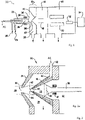
- Fig. 1 schematically illustrates a conventional ICP-MS 10 with an ion source 20 in the form of an inductively coupled plasma torch having a central tube for conveying the analyte sample AS in a carrier gas into a plasma 28 produced in the torch.
- the ion source 20 further includes an intermediate tube for conveying a plasma forming gas 24 and an auxiliary gas 26, which can e.g. be argon or nitrogen, a radio frequency coil 30 arranged around the outer tube.
- the mass spectrometer further comprises an interface arrangement 32 for transferring the analyte sample and plasma flux 28 into the analyzing part of the ICP-MS including an interface structure comprising a sampling cone 34 and a skimmer cone 40. Both cones 34, 40 each have a hole 36, 42 at its apex through which the plasma flux 28 passes from the ion source 20 into a fist 38 and second 44 vacuum region.
- the cones 34, 40 are typically water-cooled.
- the second vacuum region 44 in the embodiment shown further comprises an ion extraction electrode 46 and other ion optics [not shown] all being part of the ion optical system, which serves for extracting an ion beam from the plasma flux 28 into a third pumped vacuum region 48 and towards mass analyzer 50 which separates the ions according to their mass-to-charge-ratio and towards detector 52, where the detected ions are read out by recording means 54.
- mass analyzers 50 such as a quadrupole or time-of-flight (TOF) mass analyzer 50 may be employed. Utilizing a TOF analyzer has the advantage of being capable of discriminating resulting polyatomic ions.
- the interface arrangement 32 used for carrying out the method according to the present invention comprises at least one passage with an inlet and an outlet, the passage leading from an outside of the interface structure into a reaction zone formed in an area surrounding the outlet of the passage as illustrated in Fig. 2 , exemplarily showing preferred embodiments for an interface arrangement 32 with at least one passage in at least one cone.
- the interface arrangement 32 shown in Fig. 2a has a sampling cone 34 and a skimmer cone 40 similar to that shown in Fig. 1 .
- the ion plasma flux 28 flows through hole 36 in sampling cone 34 into the first vacuum region 38 and through hole 42 into the second vacuum region 44 held at a pressure lower than that of the first vacuum region.
- the skimmer cone 40 includes a passage 60 leading from an inlet 62 to an outlet 63 at the hole 42 of the skimmer cone 40. While such arrangement conventionally was used to create a reaction/collision zone, the present invention uses the passage 60 to supply the analyte substance AS into the reaction zone 64 where it interacts with the plasma 28 thereby softly ionizing the analyte substance AS.
- the exact dimensions of the reaction zone 64 depend on several factors, e.g. properties of the plasma.
- the shape of the reaction zone in Fig. 2a is thus only exemplarily and can vary from device to device.
- FIG. 2b A second preferred embodiment of the interface arrangement 32 is shown in Fig. 2b .
- the sampling cone 34 comprises a second passage 74 with inlet 72 and outlet 75 creating a second reaction zone 76 in proximity to hole 36.
- the two passages 60 and 74 can be used in different ways.
- a reagent gas RG may be supplied via passage 72 while the analyte sample AS is supplied via passage 60.
- the reagent substance RS may also provided via passage 60 while the analyte sample AS is supplied via passage 74.
- One single passage 60, 74 can also be used for supplying both reagent substance RS and analyte sample AS.
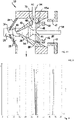
- FIG. 2c A third preferred embodiment for an interface arrangement 32 is shown in Fig. 2c .
- the skimmer cone 40 is provided with two passages 60 and 88.
- the third passage 88 also has an inlet 90 and an outlet 91, which in the present embodiment leads into the first reaction zone 64.
- the interface arrangement 32 includes a sampler cone 34 and a skimmer cone 40 followed by an ion optical system including an ion extraction electrode 45 mounted on the skimmer cone 40 by a dielectric seal 45a and other electrodes 46 and 47 to extract ion beam 58.
- the at least one passage 94 is provided behind the skimmer cone 40 for supplying the analyte sample AS into reaction zone 95.
- the present invention provides for a possibility to combine conventional ICP-MS for elemental analysis with organic analysis of molecules in one single device.
- passages 60, 74, 88, 94 conventionally provided for reducing interferences by supplying collision gases, now and for the first time, are used to supply the analyte sample AS into the mass spectrometry device.
- the analyte sample AS in particular a molecular sample, are either ionized by the incoming already cooled down plasma, the residual plasma, or by a carrier gas, e.g. stemming from the ion source 20.
- Fig. 3 shows two mass spectra of propane, mass spectrum 1 obtained with a conventional ICP mass spectrometer apparatus 10, and mass spectrum 2 obtained with a method and device 10 according to the present invention, i.e. the analyte sample AS is introduced via a passage 60, 74, 88, 94 of interface arrangement 32, using an entrance-based collision/reaction cell.
- the analyte sample AS is introduced into the passage 60, 74, 88, 94 instead of directly providing it to the area where the plasma is produced, the ionization process of the analyte sample AS becomes much softer and does not lead to a decomposition of the molecules (spectrum 2), compared to the standard procedures used in ICP-MS (spectrum 1).
Abstract
Description
- The present invention relates to a method of operating an inductively coupled plasma mass spectrometry apparatus for analyzing a molecular analyte substance or a mixture of at least two substances.
- Inductively coupled plasma mass spectrometers (ICP-MS) are e.g. used for trace element analysis. Typically, an ICP-MS analysis involves the complete atomization and subsequent ionization of the test sample by means of a plasma source before the resulting elemental ions are quantified by the spectrometer. Up to now, several different types of ICP-MS are available, as e. g. the quadrupole ICP-MS or time-of-flight ICP-MS.
- A common problem of any ICP-MS analysis is the possible occurrence of interferences caused by newly forming polyatomic ions or molecules. Such interferences are often addressed by means of reaction/collision cells in the respective ICP-MS system. Thereby, reagent gases are added to the reaction/collision cell to provide for a separation of analyte ions from interferences based upon their energy differences. An exemplarily ICP-MS system for improved attenuation of interferences are described in
US 7,329,863 B2 andUS 7,119,330 B2 . - ICP-MS systems are less suitable or even unsuitable for the analysis of molecules, which are typically investigated by mass spectrometers employing different types of ionization sources, e.g. electrospray-ionization (ESI) or atmospheric pressure chemical ionization (APCI). Such methods are optimized for the ionization of molecules and do not lead to an atomization of them.
- Other mass spectrometry systems suitable for molecular analysis are e.g. the selectedion flow-tube mass spectrometer (SIFT-MS) or the proton-transfer-reaction mass spectrometer (PTR-MS)
- However, up to now, no mass spectrometry system is available, which allows for the analysis of atomized and ionized molecules in one single device.
- Therefore, the objective technical problem underlying the present invention is to provide such possibility for analyzing atomized and ionized molecules in one single device.
- This object is achieved by the method according to
claim 1 and by the use according to claim 13. - Regarding the method, the object is achieved by a method of operating an inductively coupled plasma mass spectrometry apparatus for analyzing an analyte sample, the mass spectrometry apparatus including a plasma ion source, a mass analyzer and an interface arrangement positioned between the plasma ion source and the mass analyzer of the mass spectrometer, the interface arrangement at least comprising an interface structure in the form of a cone, e.g. a sampling cone or a skimmer cone, and at least one passage with an inlet and an outlet, the passage leading from an outside of the interface structure into a reaction zone formed in an area surrounding the outlet of the passage.
- The method comprises the steps of
- Generating a plasma using the plasma ion source and forming a plasma flux to flow towards the mass analyzer,
- supplying the analyte sample into the reaction zone via the passage such that the analyte sample interacts with the plasma flux, and
- analyzing the analyte sample using the mass analyzer.
- The molecular analyte substance or mixture may initially be provided in the form of a gas, a vapor or a liquid. The analyte sample preferably is a molecular analyte substance or a mixture of at least two substances.
- The interface structure may comprise one or more cones, e.g. it can comprise a sampler and a skimmer cone, or a sampler cone, a skimmer cone and at least one additional cone.
- The passage used for introducing the substance or mixture may e.g. be such as described in
US 7,329,863 B2 andUS 7,119,330 B2 . In the context of the present invention full reference is made to both references. The passages in the references given, however are used for an entirely different purpose, which is attenuating interferences. The same set-up can however also be used to facilitate molecular analysis by means of an ICP-MS, as suggested by the present invention. - The present invention advantageously allows to analyze analyte samples, in particular a molecular sample, by means of an ICP-MS utilizing an entrance-based collision/reaction cell. The analyte sample is supplied via the at least one passage such that an ion beam is formed in the reaction zone which proceeds towards the mass analyzer.
- In case of a typical ICP-MS, the plasma into which the analyte sample is introduced, usually has a relatively high pressure (e.g. atmospheric pressure). The plasma vaporizes and ionizes the sample, and the ions are subsequently extracted and transferred to a mass analyzer via a differentially-pumped interface, the mass analyzer usually operated at a relatively low pressure, typically at <10-5 Torr. The space between succeeding cones decreases in a stepwise manner. By introducing the analyte sample into the passage instead of directly providing it to the area where the plasma is produced, an ionization process of the analyte sample becomes possible which is much softer and does not lead to a, especially complete, decomposition of the molecules, compared to the standard procedures used in ICP-MS. The suggested procedure further enables parallel ionization of polar and unpolar analytes, as well as ionization of gaseous and liquid analytes and also for fragmentation of molecules on purpose.
- In one embodiment of the present invention, at least one reagent substance is added which serves for producing specific ions of the analyte sample by chemical ionization. The reagent substance may e.g. be added via the at least one passage.
- Advantageously, the reagent substance is one of H2, O2, H2O, NH3, NO3 or any ionized, protonated or deprotonated derivative therefrom.
- Another embodiment comprises that a microwave induced plasma source is used as plasma ion source. Using an ion source which comprises a microwave generator has the advantage that high field strengths can be achieved along with low power dissipation. A uniform and energy efficient plasma can thus be achieved in a straightforward manner. In this regard reference is made to
DE202020106423U1 US2016/0026747A1 andWO2017/176131A1 . In particular, such microwave based plasma ion source may comprise a dielectric resonator. - It is of advantage, if argon, nitrogen, krypton, xenon, neon, helium or any mixture of at least two gases is used as a carrier gas for the plasma ion source. The choice of carrier gas depends on the reactions that are to be induced. In this regard, nitrogen particularly leads to additional reactions with reagent gases or molecules, it can be used as a carrier gas and for ionization.
- One embodiment comprises that the analyte sample is split into at least two sub-parts based on at least one physical and/or chemical property of its components, e.g. size or electrical charge, before being supplied into reaction zone via the passage, wherein the sub-parts are especially separately supplied into the reaction zone one after the other. Such splitting can advantageously be achieved by various separation and/or fractionation methods, such as gas or liquid chromatography, or, especially capillary, electrophoresis. For this purpose, the mass spectrometry apparatus can include appropriate means for separating, splitting or fractionation of an analyte sample, e.g. a gas or liquid chromatography or electrophoresis unit.
- A further embodiment comprises that the mass spectrometer is provided with an ion optical system establishing a reflecting electrostatic field for reflecting ions along a desired path towards the mass analyzer. Such ion optical system may include any arrangement capable of deflecting a quantity of ions between two non-parallel planes, e. g. ion mirrors, reflectors, deflectors, quadrupole ion deflectors, electrostatic energy analyzers, magnetic ion optics, ion multiple guides, and the like. One preferred embodiment employs an arrangement of an ion optics "IonMirror" devices, as described in
US patent no 6,614,021 (incorporated herein by reference), or those disclosed inUS 5,559,337 ,US 5,773,823 ,US 5,804,821 ,US 6,031,579 ,US 6,815,667 ,US 6,630,665 , orUS 6,6306,651 - In another embodiment of the method, the interface structure
- separates a first vacuum region at a relatively high pressure adjacent a first surface of said interface structure, which receives the plasma flux from the plasma ion source from a second vacuum region at a relatively low pressure adjacent a second surface of said interface structure, which leads to the mass analyzer, and
- provides an aperture having axial extension forming the reaction zone located between the first surface and the second surface of the interface structure, through which the plasma flux flows from the first region towards the second region, and
- The analyte sample thus is directed into the reaction zone where it interacts with the plasma which is already at a lower pressure compared to the pressure in the area of the plasma ion source. This makes the ionization much softer and leads to notably less fragmentation processes.
- One embodiment comprises that the interface arrangement at least comprises a sampling cone and a skimmer cone, the skimmer cone being arranged behind the sampling cone.
- Yet, in another embodiment, at least two passages are provided in the interface arrangement. The at least two passages may be provided in the same cone or in two different cones, e. g. one in the skimmer cone and one in the sampling cone. By providing more than one passage, more than one reaction zone is created enabling for multi-reactions.
- In one embodiment, the passage is completely located within at least one cone, e.g. the sampler, the skimmer cone or any other cone. Such device is e. g. suggested in
US 7,329,863 B2 . - In another embodiment however, the passage is located behind the sampler cone, the skimmer cone or any other cone, as described in
US 7,119,330 B2 . - In a further embodiment the analyte sample and/or the reagent substance is/are supplied via the passage at least during a first time interval and supplied to an area of the plasma ion source, where the plasma id formed, at least during a second time interval. By this procedure, a conventional ICP-MS analysis relating to a structural analysis can be combined with a molecular analysis. The first and second time interval can be carried out alternately, or can be initiated on demand.
- The object of the present invention is further achieved by use of an inductively coupled mass spectrometry apparatus, the mass spectrometry apparatus including a plasma ion source, a mass analyzer and an interface arrangement positioned between the plasma ion source and the mass analyzer of the mass spectrometer, the interface arrangement at least comprising an interface structure in the form of a cone of the interface arrangement, e.g. a sampling cone or a skimmer cone, and at least one passage with an inlet and an outlet, the passage leading from an outside of the interface structure into a reaction zone formed in an area surrounding the outlet of the passage, for analyzing a molecular analyte sample. The mass spectrometry apparatus is in particular used for molecular analysis by carrying out a method according to at least one of the embodiments described above.
- The present invention as well as its preferred embodiments will be further explained based on the figures
Fig. 1 - Fig. 3 . -
Fig. 1 shows a conventional ICP-MS according to the state of the art; -
Fig. 2 shows exemplary and preferred embodiments for an interface arrangement with at least one cone having at least one passage for introducing the analyte sample; and -
Fig. 3 a mass spectrum of propane obtained with the inventive method. - In the figures, same elements are provided with the same reference numbers.
-
Fig. 1 schematically illustrates a conventional ICP-MS 10 with anion source 20 in the form of an inductively coupled plasma torch having a central tube for conveying the analyte sample AS in a carrier gas into aplasma 28 produced in the torch. Theion source 20 further includes an intermediate tube for conveying a plasma forming gas 24 and anauxiliary gas 26, which can e.g. be argon or nitrogen, aradio frequency coil 30 arranged around the outer tube. - The mass spectrometer further comprises an
interface arrangement 32 for transferring the analyte sample andplasma flux 28 into the analyzing part of the ICP-MS including an interface structure comprising asampling cone 34 and askimmer cone 40. Bothcones hole plasma flux 28 passes from theion source 20 into afist 38 and second 44 vacuum region. Thecones second vacuum region 44 in the embodiment shown further comprises anion extraction electrode 46 and other ion optics [not shown] all being part of the ion optical system, which serves for extracting an ion beam from theplasma flux 28 into a third pumpedvacuum region 48 and towardsmass analyzer 50 which separates the ions according to their mass-to-charge-ratio and towardsdetector 52, where the detected ions are read out by recording means 54. Differentmass analyzers 50, such as a quadrupole or time-of-flight (TOF)mass analyzer 50 may be employed. Utilizing a TOF analyzer has the advantage of being capable of discriminating resulting polyatomic ions. - The
interface arrangement 32 used for carrying out the method according to the present invention comprises at least one passage with an inlet and an outlet, the passage leading from an outside of the interface structure into a reaction zone formed in an area surrounding the outlet of the passage as illustrated inFig. 2 , exemplarily showing preferred embodiments for aninterface arrangement 32 with at least one passage in at least one cone. - The
interface arrangement 32 shown inFig. 2a has asampling cone 34 and askimmer cone 40 similar to that shown inFig. 1 . Theion plasma flux 28 flows throughhole 36 insampling cone 34 into thefirst vacuum region 38 and throughhole 42 into thesecond vacuum region 44 held at a pressure lower than that of the first vacuum region. Theskimmer cone 40 includes apassage 60 leading from aninlet 62 to anoutlet 63 at thehole 42 of theskimmer cone 40. While such arrangement conventionally was used to create a reaction/collision zone, the present invention uses thepassage 60 to supply the analyte substance AS into thereaction zone 64 where it interacts with theplasma 28 thereby softly ionizing the analyte substance AS. The exact dimensions of thereaction zone 64 depend on several factors, e.g. properties of the plasma. The shape of the reaction zone inFig. 2a is thus only exemplarily and can vary from device to device. - A second preferred embodiment of the
interface arrangement 32 is shown inFig. 2b . In contrast to the embodiment shown inFig. 2a , in case ofFig. 2b thesampling cone 34 comprises asecond passage 74 withinlet 72 andoutlet 75 creating asecond reaction zone 76 in proximity to hole 36. The twopassages Fig. 2a , a reagent gas RG may be supplied viapassage 72 while the analyte sample AS is supplied viapassage 60. However, in other embodiments, e.g. the reagent substance RS may also provided viapassage 60 while the analyte sample AS is supplied viapassage 74. Onesingle passage - A third preferred embodiment for an
interface arrangement 32 is shown inFig. 2c . In contrast to the embodiment shown inFig. 2b , theskimmer cone 40 is provided with twopassages third passage 88 also has aninlet 90 and anoutlet 91, which in the present embodiment leads into thefirst reaction zone 64. Again, many different possibilities exist for using thedifferent passages - Finally, another preferred embodiment of the
interface arrangement 32 is subject toFig. 2c . Again, theinterface arrangement 32 includes asampler cone 34 and askimmer cone 40 followed by an ion optical system including anion extraction electrode 45 mounted on theskimmer cone 40 by adielectric seal 45a andother electrodes ion beam 58. For this embodiment, the at least onepassage 94 is provided behind theskimmer cone 40 for supplying the analyte sample AS intoreaction zone 95. - It shall be noted that the different embodiments for the
interface arrangement 32 shown can arbitrarily combined with each other. Further, it shall be noted that the present invention is by no means limited to the embodiments shown. For instance, any embodiment for aninterface arrangement 32 orinterface structure US 7,329,863 B2 andUS 7,119,330 B2 . - In summary, the present invention provides for a possibility to combine conventional ICP-MS for elemental analysis with organic analysis of molecules in one single device. To achieve this,
passages ion source 20. - It is furthermore possible to add additional reagent substances RD via the at least one
passage -
Fig. 3 shows two mass spectra of propane,mass spectrum 1 obtained with a conventional ICPmass spectrometer apparatus 10, andmass spectrum 2 obtained with a method anddevice 10 according to the present invention, i.e. the analyte sample AS is introduced via apassage interface arrangement 32, using an entrance-based collision/reaction cell. By introducing the analyte sample AS into thepassage spectrum 2 the propane molecules of the analyte sample AS shown inFig. 3 remain intact (44 Da) or partially fragmented (e.g. 43 Da - corresponding to a loss of one hydrogen, 26-30 DA - corresponding to various C2Hn fragments). The present invention therefore expands the scope of application of ICP-MS devices towards molecular analysis in a straightforward manner. -
- 10
- ICP-MS
- 20
- ion source
- 28
- plasma
- 24
- plasma forming gas
- 26
- auxiliary gas
- 30
- radio frequency coil
- 32
- interface arrangement
- 34
- sampling cone
- 40
- skimmer cone
- 36
- hole sampling cone
- 42
- hole skimmer cone
- 38
- first vacuum region
- 44
- second vacuum region
- 45, 46, 47
- electrodes of ion optical system
- 50
- mass analyzer
- 52
- detector
- 54
- recording means
- 60,74,88,94
- passages
- 62, 72, 90
- inlets
- 63, 75, 91
- outlets
- 63, 76, 95
- reaction zones
- AS
- analyte sample
- RS
- reagent substance
Claims (14)
- Method of operating an inductively coupled plasma mass spectrometry apparatus (10) for analyzing an analyte sample (AS),
the mass spectrometry apparatus (10) including a plasma ion source (20), a mass analyzer (50) and an interface arrangement (32) positioned between the plasma ion source (20) and the mass analyzer (50) of the mass spectrometer (10), the interface arrangement (32) at least comprising an interface structure (34,40) in the form of a cone, e.g. a sampling cone (34) or a skimmer cone (40), and at least one passage (60,74,88,94) with an inlet (62,72,90) and an outlet (63,75,91), the passage (60,74,88,94) leading from an outside of the interface structure (32) into a reaction zone (63,76,95) formed in an area surrounding the outlet (63,75,91) of the passage (60,74,88,94),
the method comprising the steps of- generating a plasma (28) using the plasma ion source (20) and forming a plasma flux (28) to flow towards the mass analyzer,- supplying the analyte sample (AS) into the reaction zone (63,76,95) via the passage (60,74,88,94) such that the analyte sample (AS) interacts with the plasma flux (28), and- analyzing the analyte sample (AS) using the mass analyzer (50). - Method according to claim 1,
wherein at least one reagent substance (RS) is added which serves for producing specific ions of the analyte sample (AS) by chemical ionization. - Method according to claim 2,
wherein the reagent substance (RS) is one of H2, O2, H2O, NH3, NO3 or any ionized, protonated or deprotonated derivative therefrom. - Method according to any of the preceding claims,
wherein a microwave induced plasma source is used as plasma ion source (20). - Method according to claim 5
wherein argon, nitrogen, krypton, xenon, neon, helium or any mixture of at least two gases is used as a carrier gas for the plasma ion source (20). - Method according to any of the preceding claims,
wherein the analyte sample (AS) is split into at least two sub-parts based on at least one physical and/or chemical property of its components before being supplied into reaction zone (63,76,95) via the passage (60,74,88,94), and wherein the sub-parts are especially separately supplied into the reaction zone (63, 76, 95) one after the other. - Method according to any of the preceding claims,
wherein the mass spectrometer (10) is provided with an ion optical system (45-47) establishing a reflecting electrostatic field for reflecting ions along a desired path towards the mass analyzer (50). - Method according to any of the preceding claims,
wherein the interface structure (34,40)∘ separates a first vacuum region at a relatively high pressure (38) adjacent a first surface of said interface structure (34,40), which receives the plasma flux (28) from the plasma ion source (20) from a second vacuum region (44) at a relatively low pressure adjacent a second surface of said interface structure (34,40), which leads to the mass analyzer (50), and∘ provides an aperture having axial extension forming the reaction zone (63, 76, 95) located between the first surface and the second surface of the interface structure (34, 40), through which the plasma flux (28) flows from the first region (38) towards the second region (40), andwherein the passage (60,74,88,94) leads into the reaction zone (63, 76, 95) formed in the aperture of the interface structure (34, 40). - Method according to any of the preceding claims,
wherein the interface arrangement (32) at least comprises a sampling cone (34) and a skimmer cone (40), the skimmer cone (40) being arranged behind the sampling cone (34). - Method according to any of the preceding claims,
wherein at least two passages (60,74,88,94) are provided in the interface arrangement (32). - Method according to any of the preceding claims,
wherein the passage (60,74,88,94) is completely located within at least one cone (34,40), e.g. the sampler (34), the skimmer cone (40) and/or any additional cone. - Method according to any of the claims 1-9,
wherein the passage (60,74,88,94) is located behind the sampler cone (34), the skimmer cone (40) and/or any additional cone. - Method according to any of the preceding claims,
wherein the analyte sample (AS) and/or the reagent substance (RS) is/are supplied via the passage (60,74,88,94) at least during a first time interval, and wherein the analyte sample (AS) and/or the reagent substance (RS) is/are supplied into an area of the plasma ion source (20) at least during a second time interval. - Use of an inductively coupled mass spectrometry apparatus (10), the mass spectrometry apparatus (10) including a plasma ion source (20), a mass analyzer (50) and an interface arrangement (32) positioned between the plasma ion source (20) and the mass analyzer (50) of the mass spectrometer (10), the interface arrangement (32) at least comprising an interface structure (34,40) in the form of a cone of the interface arrangement (32), e.g. a sampling cone (34) or a skimmer cone (40), and at least one passage (60,74,88,94) with an inlet (62,72,90) and an outlet (63,75,91), the passage (60,74,88,94) leading from an outside of the interface structure (32) into a reaction zone (63,76,95) formed in an area surrounding the outlet (63,75,91) of the passage (60,74,88,94) for analyzing a molecular analyte sample (AS).
Priority Applications (3)
| Application Number | Priority Date | Filing Date | Title |
|---|---|---|---|
| EP21173703.6A EP4089716A1 (en) | 2021-05-12 | 2021-05-12 | Mass spectrometry apparatus |
| CN202210497006.9A CN115346854A (en) | 2021-05-12 | 2022-05-09 | Mass spectrometer |
| US17/663,074 US20220367167A1 (en) | 2021-05-12 | 2022-05-12 | Mass spectrometry apparatus |
Applications Claiming Priority (1)
| Application Number | Priority Date | Filing Date | Title |
|---|---|---|---|
| EP21173703.6A EP4089716A1 (en) | 2021-05-12 | 2021-05-12 | Mass spectrometry apparatus |
Publications (1)
| Publication Number | Publication Date |
|---|---|
| EP4089716A1 true EP4089716A1 (en) | 2022-11-16 |
Family
ID=75919228
Family Applications (1)
| Application Number | Title | Priority Date | Filing Date |
|---|---|---|---|
| EP21173703.6A Pending EP4089716A1 (en) | 2021-05-12 | 2021-05-12 | Mass spectrometry apparatus |
Country Status (3)
| Country | Link |
|---|---|
| US (1) | US20220367167A1 (en) |
| EP (1) | EP4089716A1 (en) |
| CN (1) | CN115346854A (en) |
Citations (15)
| Publication number | Priority date | Publication date | Assignee | Title |
|---|---|---|---|---|
| US5559337A (en) | 1993-09-10 | 1996-09-24 | Seiko Instruments Inc. | Plasma ion source mass analyzing apparatus |
| US5773823A (en) | 1993-09-10 | 1998-06-30 | Seiko Instruments Inc. | Plasma ion source mass spectrometer |
| US5804821A (en) | 1996-05-15 | 1998-09-08 | Seiko Instruments Inc. | Plasma ion source mass analyzer |
| US6031579A (en) | 1997-05-05 | 2000-02-29 | Thomas R. Vigil | Weather parameter display system |
| US6614021B1 (en) | 1998-09-23 | 2003-09-02 | Varian Australian Pty Ltd | Ion optical system for a mass spectrometer |
| US6630665B2 (en) | 2000-10-03 | 2003-10-07 | Mds Inc. | Device and method preventing ion source gases from entering reaction/collision cells in mass spectrometry |
| WO2004012223A1 (en) * | 2002-07-31 | 2004-02-05 | Varian Australia Pty Ltd | Mass spectrometry apparatus and method |
| US6815667B2 (en) | 2000-08-30 | 2004-11-09 | Mds Inc. | Device and method for preventing ion source gases from entering reaction/collision cells in mass spectrometry |
| US7119330B2 (en) | 2002-03-08 | 2006-10-10 | Varian Australia Pty Ltd | Plasma mass spectrometer |
| WO2012024570A2 (en) * | 2010-08-19 | 2012-02-23 | Leco Corporation | Mass spectrometer with soft ionizing glow discharge and conditioner |
| US20160026747A1 (en) | 2014-07-24 | 2016-01-28 | Mitsubishi Electric Research Laboratories, Inc. | Method for Determining a Sequence for Drilling Holes According to a Pattern using Global and Local Optimization |
| WO2017176131A1 (en) | 2016-04-05 | 2017-10-12 | Edward Reszke | An adapter shaping electromagnetic field, which heats toroidal plasma discharge at microwave frequency |
| EP3234978A1 (en) * | 2014-12-16 | 2017-10-25 | Carl Zeiss SMT GmbH | Ionization device and mass spectrometer therewith |
| US20180240662A1 (en) * | 2017-02-23 | 2018-08-23 | Thermo Fisher Scientific (Bremen) Gmbh | Methods in mass spectrometry using collision gas as ion source |
| DE202020106423U1 (en) | 2020-11-10 | 2021-02-08 | Analytik Jena Ag | Mass spectrometry device |
Family Cites Families (2)
| Publication number | Priority date | Publication date | Assignee | Title |
|---|---|---|---|---|
| JP2753265B2 (en) * | 1988-06-10 | 1998-05-18 | 株式会社日立製作所 | Plasma ionization mass spectrometer |
| US6265717B1 (en) * | 1998-07-15 | 2001-07-24 | Agilent Technologies | Inductively coupled plasma mass spectrometer and method |
-
2021
- 2021-05-12 EP EP21173703.6A patent/EP4089716A1/en active Pending
-
2022
- 2022-05-09 CN CN202210497006.9A patent/CN115346854A/en active Pending
- 2022-05-12 US US17/663,074 patent/US20220367167A1/en active Pending
Patent Citations (16)
| Publication number | Priority date | Publication date | Assignee | Title |
|---|---|---|---|---|
| US5773823A (en) | 1993-09-10 | 1998-06-30 | Seiko Instruments Inc. | Plasma ion source mass spectrometer |
| US5559337A (en) | 1993-09-10 | 1996-09-24 | Seiko Instruments Inc. | Plasma ion source mass analyzing apparatus |
| US5804821A (en) | 1996-05-15 | 1998-09-08 | Seiko Instruments Inc. | Plasma ion source mass analyzer |
| US6031579A (en) | 1997-05-05 | 2000-02-29 | Thomas R. Vigil | Weather parameter display system |
| US6614021B1 (en) | 1998-09-23 | 2003-09-02 | Varian Australian Pty Ltd | Ion optical system for a mass spectrometer |
| US6815667B2 (en) | 2000-08-30 | 2004-11-09 | Mds Inc. | Device and method for preventing ion source gases from entering reaction/collision cells in mass spectrometry |
| US6630665B2 (en) | 2000-10-03 | 2003-10-07 | Mds Inc. | Device and method preventing ion source gases from entering reaction/collision cells in mass spectrometry |
| US7119330B2 (en) | 2002-03-08 | 2006-10-10 | Varian Australia Pty Ltd | Plasma mass spectrometer |
| WO2004012223A1 (en) * | 2002-07-31 | 2004-02-05 | Varian Australia Pty Ltd | Mass spectrometry apparatus and method |
| US7329863B2 (en) | 2002-07-31 | 2008-02-12 | Varian Australia Pty, Ltd. | Mass spectrometry apparatus and method |
| WO2012024570A2 (en) * | 2010-08-19 | 2012-02-23 | Leco Corporation | Mass spectrometer with soft ionizing glow discharge and conditioner |
| US20160026747A1 (en) | 2014-07-24 | 2016-01-28 | Mitsubishi Electric Research Laboratories, Inc. | Method for Determining a Sequence for Drilling Holes According to a Pattern using Global and Local Optimization |
| EP3234978A1 (en) * | 2014-12-16 | 2017-10-25 | Carl Zeiss SMT GmbH | Ionization device and mass spectrometer therewith |
| WO2017176131A1 (en) | 2016-04-05 | 2017-10-12 | Edward Reszke | An adapter shaping electromagnetic field, which heats toroidal plasma discharge at microwave frequency |
| US20180240662A1 (en) * | 2017-02-23 | 2018-08-23 | Thermo Fisher Scientific (Bremen) Gmbh | Methods in mass spectrometry using collision gas as ion source |
| DE202020106423U1 (en) | 2020-11-10 | 2021-02-08 | Analytik Jena Ag | Mass spectrometry device |
Also Published As
| Publication number | Publication date |
|---|---|
| CN115346854A (en) | 2022-11-15 |
| US20220367167A1 (en) | 2022-11-17 |
Similar Documents
| Publication | Publication Date | Title |
|---|---|---|
| US10923338B2 (en) | Ion focusing | |
| US11133162B2 (en) | IRMS sample introduction system and method | |
| US7820980B2 (en) | High speed combination multi-mode ionization source for mass spectrometers | |
| JP3493460B2 (en) | Plasma mass spectrometer | |
| US20090179150A1 (en) | Mass spectrometer with looped ion path | |
| US8299427B2 (en) | Mass spectrometer | |
| JP2013545243A (en) | Improvements in and related to mass spectrometry | |
| US9305758B2 (en) | Interface for mass spectrometry apparatus | |
| US7935922B2 (en) | Ion guide chamber | |
| US11031227B2 (en) | Discharge chambers and ionization devices, methods and systems using them | |
| EP4089716A1 (en) | Mass spectrometry apparatus | |
| US9048078B2 (en) | Mass spectrometry | |
| Egorova et al. | Characteristics of an ion funnel as ion guide in an inductively coupled plasma mass spectrometer | |
| WO2021095105A1 (en) | Mass spectrometry method and mass spectrometer | |
| EP4170696A1 (en) | Ion activation and fragmentation in sub-ambient pressure for ion mobility and mass spectrometry |
Legal Events
| Date | Code | Title | Description |
|---|---|---|---|
| PUAI | Public reference made under article 153(3) epc to a published international application that has entered the european phase |
Free format text: ORIGINAL CODE: 0009012 |
|
| STAA | Information on the status of an ep patent application or granted ep patent |
Free format text: STATUS: THE APPLICATION HAS BEEN PUBLISHED |
|
| AK | Designated contracting states |
Kind code of ref document: A1 Designated state(s): AL AT BE BG CH CY CZ DE DK EE ES FI FR GB GR HR HU IE IS IT LI LT LU LV MC MK MT NL NO PL PT RO RS SE SI SK SM TR |
|
| STAA | Information on the status of an ep patent application or granted ep patent |
Free format text: STATUS: REQUEST FOR EXAMINATION WAS MADE |
|
| 17P | Request for examination filed |
Effective date: 20230508 |
|
| RBV | Designated contracting states (corrected) |
Designated state(s): AL AT BE BG CH CY CZ DE DK EE ES FI FR GB GR HR HU IE IS IT LI LT LU LV MC MK MT NL NO PL PT RO RS SE SI SK SM TR |
|
| RAP3 | Party data changed (applicant data changed or rights of an application transferred) |
Owner name: ANALYTIK JENA GMBH+CO. KG |