EP4089458A2 - Preconnectorized optical distribution cable assemblies and corresponding methods of deployment - Google Patents
Preconnectorized optical distribution cable assemblies and corresponding methods of deployment Download PDFInfo
- Publication number
- EP4089458A2 EP4089458A2 EP22170279.8A EP22170279A EP4089458A2 EP 4089458 A2 EP4089458 A2 EP 4089458A2 EP 22170279 A EP22170279 A EP 22170279A EP 4089458 A2 EP4089458 A2 EP 4089458A2
- Authority
- EP
- European Patent Office
- Prior art keywords
- cable
- tap
- distribution
- distribution cable
- subunit
- Prior art date
- Legal status (The legal status is an assumption and is not a legal conclusion. Google has not performed a legal analysis and makes no representation as to the accuracy of the status listed.)
- Pending
Links
Images




Classifications
-
- G—PHYSICS
- G02—OPTICS
- G02B—OPTICAL ELEMENTS, SYSTEMS OR APPARATUS
- G02B6/00—Light guides; Structural details of arrangements comprising light guides and other optical elements, e.g. couplings
- G02B6/44—Mechanical structures for providing tensile strength and external protection for fibres, e.g. optical transmission cables
- G02B6/4439—Auxiliary devices
- G02B6/4471—Terminating devices ; Cable clamps
- G02B6/4472—Manifolds
- G02B6/4475—Manifolds with provision for lateral branching
-
- G—PHYSICS
- G02—OPTICS
- G02B—OPTICAL ELEMENTS, SYSTEMS OR APPARATUS
- G02B6/00—Light guides; Structural details of arrangements comprising light guides and other optical elements, e.g. couplings
- G02B6/44—Mechanical structures for providing tensile strength and external protection for fibres, e.g. optical transmission cables
- G02B6/4439—Auxiliary devices
- G02B6/4471—Terminating devices ; Cable clamps
- G02B6/4472—Manifolds
Definitions
- This disclosure relates to preconnectorized optical distribution cable assemblies, and in particular, relates to preconnectorized optical distribution cable assemblies design and deployment capability.
- Data center design and cabling-infrastructure architecture are increasingly large and complex, which requires incorporation of high-density optical components (e.g., optical fiber densities), such as to compensate for limited space and meet increasing performance demands.
- Many data centers include fiber optic cables, which have a number of advantages in waveguide systems compared to bulky traditional conductor cables (e.g., copper). Fiber optic cables provide wide bandwidth data transmission, transport multiple signals and traffic types, and/or deliver high-speed Internet access, especially as data rates increase.
- Data centers utilize multi-fiber cables to interconnect and provide signals between building distribution frames and/or to individual unit centers (e.g., computer servers). However, the labor and cost of deploying such multi-fiber cable networks for a data center can be high. Thus, there is a desire to reduce the time and costs associated with data center construction, particularly regarding cabling installation.
- One way to improve optical infrastructure installation efficiency is to pre-engineer infrastructure components.
- Such components e.g., fiber optic cables
- Such components may be preterminated in a factory with connectors installed, tested, and packaged for fast, easy, and safe installation at a data center.
- the installer merely needs to unpack the components, pull or route the preconnectorized fiber optic cable assembly, snap-in connectors, and/or install patch cords to end equipment, etc. This saves a significant amount of time, effort, and costs compared to on-site connectorization and assembly of cables.
- the present disclosure relates to a distribution cable assembly that has various features to enable flexible configurations to accommodate various data center configurations.
- a distribution cable assembly comprising: a distribution cable having a distribution end and a plurality of subunit cables within the distribution cable; a plurality of tap points positioned along a length of the distribution cable, wherein the plurality of tap points are each configured to route one of the plurality of subunit cables away from a remainder of the plurality of subunit cables to form a respective tap cable and the plurality of tap points are spaced apart in a first configuration; wherein the plurality of tap points are adjustable such that the plurality of tap points are spaced apart in a second configuration that is different than the first configuration.
- each tap point of the plurality of tap points is adjustable such that a first quantity of the plurality of tap points is changed to a second quantity of the plurality of tap points, wherein the second quantity is different than the first quantity.
- each tap point of the plurality of tap points comprises a first half and a second half, wherein the first half and the second half couple to each other in a snap fit configuration to define a main passage and a drop cable passage separated by an interior wall.
- each tap point of the plurality of tap points includes a first aperture, a second aperture, and a third aperture wherein the first aperture and the second aperture define the main passage, and wherein the third aperture and the interior wall define the drop cable passage.
- the distribution cable assembly further including a first grommet applied onto edges of the first aperture and a second grommet applied onto edges of the second aperture. In an alternate embodiment, the distribution cable assembly further including a third grommet applied onto edges of the third aperture. In an alternate embodiment, the distribution cable assembly further including a boot assembly extending through the third aperture and into the drop cable passage.
- each tap point of the plurality of tap points routes a respective subunit cable to form a respective a tap cable, and wherein each tap cable has a respective length. In an alternate embodiment, at least one of the respective lengths of the tap cables are different with respect to the respective length of another tap cable.
- the distribution cable assembly further comprises: a pulling grip positioned between the distribution end and the plurality of tap points.
- the distribution cable comprises a mesh material having perforations through which at least one subunit cable of the plurality of subunit cables is fed through.
- a tap point assembly comprising: a tap point comprising: a first half; a second half coupled to the first half in a snap fit configuration to define an interior of the tap point; a main passage defined by the first half and the second half, wherein the main passage terminates at a first aperture and a second aperture; an interior wall within the interior of the tap point, the interior wall defining a drop cable passage terminating at a third aperture; a distribution cable seated in the main passage from the first aperture to the second aperture, wherein the distribution cable includes at least one subunit cable within an interior of the distribution cable; and a tap cable exiting the third aperture of the tap point, wherein the tap cable is formed by a subunit cable of the at least one subunit cable that is extracted from the distribution cable and seated within the drop cable passage.
- the tap point assembly is movable along a longitudinal axis of the distribution cable.
- the distribution cable comprises a mesh material and having a perforation through which the subunit cable that forms the tap cable is extracted.
- the tap point assembly further including a first grommet applied onto edges of the first aperture and a second grommet applied onto edges of the second aperture.
- the tap point assembly further including a third grommet applied onto edges of the third aperture.
- the distribution cable assembly further including a boot assembly extending through the third aperture and into the drop cable passage.
- the drop cable passage includes a wall with a recess, and wherein the wall is substantially perpendicular to the interior wall.
- the recess of the wall is configured to hold a portion of the boot assembly.
- a method of assembling a distribution cable assembly comprising: inserting a distribution cable into a first half of a tap point, wherein the distribution cable is seated in a portion of a main passage; removing a subunit cable from the distribution cable; feeding the extracted subunit cable into a portion of a drop cable passage; and coupling a second half of the tap point onto the first half of the tap point in a snap fit configuration.
- the description relates to a distribution cable assembly that has various features to enable flexible configurations to accommodate various data center configurations.
- data center 100 includes a distribution frame region 101 and a cage region 103.
- Distribution frame region 101 includes a main distribution frame 105 that is connected to cage region 103 as discussed herein.
- a main distribution frame (MDF) 105 is connected to an intermediate distribution frame (IDF) 107.
- Intermediate distribution frames are connected to individual cabinets or servers 109 in one or more nearby rows of equipment racks within cage region 103.
- Data center 100' includes distribution frame regions 101' that each include main distribution frames 105' that are separated from each other and from cage region 103'. As shown, main distribution frames 105' are connected to information distribution frames 106, each of which are connected to each other and corresponding cage regions 103'.
- distribution cables are used throughout data center 100, 100'.
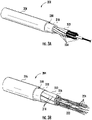
- FIGS. 3A-3B are views of a section of an example distribution cable 200, in accordance with aspects of the present disclosure.
- the distribution cable 200 includes a cable bundle 202 (may also be referred to herein as a cable core) of a plurality of subunit cables 204 and a distribution jacket 206 (may also be referred to as outer jacket, subunit jacket, etc.) defining a distribution interior 208.
- the cable bundle 202 of the subunit cables 204 is disposed in the distribution interior 208 of the distribution jacket 206.
- a strain-relief component 210 may be disposed within the distribution interior 208 of the distribution jacket 206 between the cable bundle 202 of the subunit cables 204 and the distribution jacket 206.
- the strain-relief component 210 surrounds and/or is interspersed among the cable bundle 202 of the subunit cables 204.
- an outer layer of a plurality of subunit cables 204 is stranded around an inner layer of subunit cables 204 to provide higher fiber densities. This reduces any stress or strain concentrations on any single subunit cable 204 (e.g., from bending of the distribution cable 200).
- a central strength element (not shown) may be provided, and the subunit cables 204 may be stranded around the central strength element. In yet other cable applications, stranding may not be used and the subunit cables 204 may run substantially parallel through the distribution cable 200.
- each subunit cable 204 (may also be referred to herein as a micro module, etc.) includes a subunit bundle 212 (may also be referred to herein as a subunit core) of a plurality of tether cables 214 (may also be referred to herein as tether subunits) and a subunit jacket 216 defining a subunit interior 218.
- the subunit bundle 212 of the tether cable 214 is disposed in the subunit interior 218 of the subunit jacket 216.
- a strain-relief component 220 may be disposed within the subunit interior 218 of the subunit jacket 216 between the subunit bundle 212 of the tether cables 214 and the subunit jacket 216.
- the strain-relief component 220 surrounds and/or is interspersed among the subunit bundle 212 of the subunit cables 204.
- the strain-relief component 220 may be, for example, a layer of longitudinally-extending yarns for absorbing tensile loads on the subunit bundle 212.
- the strain-relief component 220 includes a dispersed layer of aramid strands in the region between the subunit jacket 216 and the subunit bundle 212 of tether cables 214.
- a central strength element 222 may be disposed in a center of the subunit bundle 212, and thereby, within the subunit interior 218 of the subunit jacket 216.
- the tether cables 214 may be stranded (e.g., helically twisted) around the central strength element 222.
- an outer layer of a plurality of tether cables 214 is stranded around an inner layer of tether cables 214 to provide higher fiber densities. In yet other cable applications, stranding may not be used and the tether cables 214 may run substantially parallel through the subunit cable 204.
- the central strength element 222 provides strain-relief and absorbs loads from the tether cables 214.
- the subunit bundle 212 is stranded such that the tether cables 214 are helically twisted around a longitudinal axis of the subunit bundle 212. This reduces any stress or strain concentrations on any one tether cable 214 (e.g., from bending of the distribution cable 200 and/or subunit cable 204).
- Each tether cable 214 includes one or more optical fibers 224 (may also be referred to herein as optical fiber waveguides).
- the strain-relief component 210 and/or strain-relief component 220 may utilize tensile yarns as tension relief elements that provide tensile strength to the cables 200, 204, 214.
- a preferred material for the tensile yarns is aramid (e.g., KEVLAR ® ), but other tensile strength materials could be used, such as high molecular weight polyethylenes (e.g., SPECTRA ® fiber and DYNEEMA ® fiber, Teijin Twaron ® aramids, fiberglass, etc.).
- distribution cable 200 includes a distribution jacket 206 that defines distribution interior 208 in which a cable bundle 202 of a plurality of subunit cables 204 are housed. Also, as shown, distribution cable 200 does not include strain relief component 210 thereby allowing direct access to the plurality of subunit cables 204 beneath distribution jacket 206 as discussed below.
- Distribution cable 200 is made of a mesh material that is wrapped around plurality of subunit cables 204.
- the mesh material of distribution cable 200 provides flexibility to distribution cable 200 such that distribution cable 200 can accommodate different numbers of subunit cables depending on application and cabling requirements.
- distribution cable 200 has a perforation 205 upon which distribution cable 200 can be opened as shown in FIG. 3D to access subunit cables 204 and to route one of subunit cables 204 within tap point 320 ( FIG. 6C ) as discussed below.
- the mesh material of distribution cable 200 can be various colors, which can assist in field installation. For example, different colors could identify different information distribution frames 107 or cabinets 109 to which distribution cable 200 is associated.
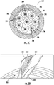
- FIG. 3C is a cross-sectional view of an embodiment of a distribution cable 200' of FIGS. 3A-3B , in accordance with aspects of the present disclosure.
- Each of the subunit cables 204' includes optical fibers 224 loosely disposed within the subunit cable 204' (e.g., in an essentially parallel array).
- the subunit cable 204' may be further encased in an interlocking armor for enhanced crush resistance.
- FIG. 4 is a cross-sectional view of another embodiment of a distribution cable 200".
- Each of the subunit cables 204" of the cable bundle 202" is a stack 201 of fiber ribbons 203.
- Each fiber ribbon 203 includes a plurality of optical fibers 224.
- FIGS. 5A-5C are embodiments of a distribution cable assembly 300 incorporating the distribution cable of FIGS. 3A-3D .
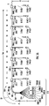
- the distribution cable assembly 300 includes a distribution subunit 302 (may also be referred to herein as a main subassembly) and a plurality of tap subunits 304(1)-304(8) (may also be referred to herein as a branch subassembly, drop subunit, etc.).
- the distribution subunit 302 includes a distribution cable 200 (may be referred to as a distribution cable portion) and distribution connectors 308 at a distribution end 310 (may also be referred to herein as upstream end).
- Each of the plurality of tap subunits 304(1)-304(8) includes a tap cable 312(1)-312(8) (may also be referred to herein as a drop cable or tap cable portion) and tap connectors 314(1)-314(8) at a tap end 316(1)-316(8) (may also be referred to herein as downstream end).
- subunit cables 204 extend from the distribution connector 308 to respectively one of the plurality of tap connectors 314(1)-314(8), each at a different tap point 320(1)-320(8) (may also be referred to herein as drop point, terminated access point, etc.) along a length of the distribution cable 200.
- subunit cable 204 extends from the distribution connector 308 through the distribution cable 200 to the tap connector 314(2).
- the spacing S1-S7 between tap points 320(1)-320(8) depends on the application and cabling requirements and can be adjusted as described below.
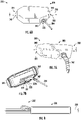
- Tap point 320 is configured to route distribution cable 200 through tap point 320 such that a subunit cable 204 can be extracted from distribution cable 200 (through perforation 205) and routed through tap point 320 to form a drop cable or tap cable 312 as shown in FIG. 6C .
- tap point 320 comprises a first half 321 and a second half 323 that couple to each other to define an interior 325.
- first half 321 and second half 323 are coupled to each other by corresponding latch 337 and grooves 339 provided on first half 321 and second half 323 that fit in a snap fit configuration.
- the snap fit of tap point 320 enables mobility of tap point 320 along a longitudinal axis A of distribution cable 200 which enables flexibility in cable installation onto a server or information data frame in a cage region of a data center.
- halves 321, 323 of tap points 320 are decoupled and moved along longitudinal axis A of distribution cable 200 to increase or decrease spacings S1-S7 between tap points 320 such that the spacing between tap points 320 can accommodate the corresponding distance/spacing between cabinets 109 in cage region 103.
- spacing S1-S7 ranges between 600 mm and 800 mm.
- the spacing S1-S7 can be adjusted in accordance to customer requirements such that in some embodiments, spacing S1-S7 can be greater than or equal to 600 mm or less than or equal to 600 mm.
- the number of tap points 320 on distribution cable assembly 300 can be adjusted based on the application and cabling requirements.
- the snap fit configuration of tap point 320 enables easy addition and removal of tap points along distribution cable 200 to accommodate various data center configurations during installation.
- distribution cable assembly 300 has a number of tap points 320 ranging between 1 and 10, or between 6 and 8.
- the number of tap points 320 can be adjusted in accordance to customer requirements such that in some embodiments, the number of tap points 320 can be outside the stated ranges above.
- tap point 320 is made of a plastic material such as polycarbonate (PC) + acrylonitrile butadiene styrene (ABS) or polyetherimide (e.g., ULTEM ® ) or polyethersulfone (PESU).
- PC polycarbonate
- ABS acrylonitrile butadiene styrene
- PESU polyethersulfone
- Interior 325 comprises a main passage 327 and a drop cable passage 329.
- Main passage 327 is defined between aperture 331 and aperture 333 of tap point 320 and is configured to receive and allow distribution cable 200 to pass through tap point 320. That is, main passage 327 has a width that corresponds to a width of distribution cable 200 such that distribution cable 200 can be seated within main passage 327.
- tap point assembly 350 comprises tap point 320 where distribution cable 200 is seated within main passage 327, and subunit cable 204 is extracted from distribution cable 200 (through perforation 205) and inserted into and through drop cable passage 329.
- Drop cable passage 329 is an off shoot of main passage 327 and is defined by interior wall 328, which physically separates main passage 327 from drop cable passage 329 and provides structural reinforcement onto tap point 320 and distribution cable 200. Drop cable passage 329 leads to aperture 335 where tap cable 312 exits tap point 320.
- a wall 351 is provided with a recess 353 where wall 351 is substantially perpendicular to interior wall 328, and wall 351 divides drop cable passage 329 into at least a portion 329A as described below.
- Recess 353 provides a mounting surface for tap cable 312 to rest within drop cable passage 329.
- recess 353 provides a mounting surface to which a strain relief structure (e.g., a boot assembly 347, FIG. 7B ) can engage as discussed below.
- a strain relief structure e.g., a boot assembly 347, FIG. 7B
- tap point 320 includes grommets 341, 343, and 345 coupled to apertures 331, 333, and 335 respectively to provide strain relief onto both distribution cable 200 and corresponding tap cable 312.
- tap point 320 includes grommets 341, 343 on apertures 331, 333, respectively to provide strain relief onto distribution cable 200.
- subunit cable 204 and tap cable 312 are provided with a boot assembly 347 that inserts through aperture 335 and into drop cable passage 329.
- boot assembly 347 extends into drop cable passage 329 and engages with the mounting surface provided by recess 353 of wall 351 thereby holding tap cable 312 in place with limited mobility.
- boot assembly 347 extends into drop cable passage 329 and engages with interior wall 328 and a side wall 349 of tap point 320 to hold tap cable 312 in place with limited mobility.
- Boot assembly 347 is configured to provide strain relief and improved retention (i.e., improved retention force) onto subunit cable 204 and tap cable 312 exiting tap point 320.
- a heat shrink material may be used to provide similar strain relief as boot assembly 347.
- grommets 341, 343, and 345 are made of silicon rubber or a thermoplastic elastomer.
- distribution connectors 308(1)-308(8) are in optical communication with the tap connectors 314(1)-314(8) (may be referred to generally as tap connectors 314), where the distribution cable assembly 300 is pre-connectorized, such as for connection to a patch panel (e.g., at intermediate distribution frame 105).
- the distribution cable assembly 300 includes a distribution portion 317 of the subunit cable 204 that extends for a predetermined length S0 from the distribution connectors 308(1)-308(8) through the distribution cable 200 to the first tap portion 318.
- the distribution cable assembly 300 further includes tap portions 318 of the subunit cable 204 that extend from the distribution cable 200 to the tap connectors 314(1)-314(8). Accordingly, the total length Stot of the distribution cable 200 includes S0-S7.
- the distribution subunit 302 includes a distribution tether 324 (may be referred to as a distribution tether portion) at the distribution end 310.
- the distribution cable assembly 300 includes multiple distribution tethers 324 and multiple tap tethers.
- the distribution tether 324 may be pre-connectorized and extend a predetermined length L1 from an end 325 of the distribution jacket 106.
- the distribution tether 324 includes distribution connectors 308(1)-308(8) coupled to ends of the distribution tether 324.
- the tap subunits 304(1)-304(8) are pre-connectorized such that the tap cables 312(1)-312(8) extend a predetermined length L2 from the distribution jacket 106.
- the tap subunits 304(1)-304(8) include tap connectors 314(1)-314(8) coupled to tap ends 316(1)-316(8) of the tap subunits 304(1)-304(8).
- length L1 and length L2 can be the same length.
- lengths L2 are the same length among tap connectors 314 as shown in FIGS. 10A and 10B .
- lengths L1, L2 are different.
- lengths L1 among distribution tethers 324 vary as shown in FIGS. 5C and 10B . Stated another way, lengths L1 among tap cables 312(1)- 312(8) may vary depending on the application and cabling requirements. In some embodiments, lengths L2 among tap cables 312(1)-312(8) vary.
- lengths L2 among tap cables 312(1)- 312(8) may vary depending on the application and cabling requirements.
- length L2 of tap cable 312(1) may be different than length L2 of tap cable 312(2)-312(8).
- Such variability of lengths L2 enables distribution cable assembly 300 to have flexibility in application depending on the configuration of data center 100, 100'.
- length L2 has a length ranging between about 100 mm and about 300 mm.
- lengths L1 and L2 can be adjusted or modified in accordance to data center 100, 100' construction specifications (i.e., height and size of data centers 100, 100') such that lengths L1 and L2 can be greater than or less than the stated ranges above.
- the distribution cable assembly 300' includes the distribution subunit 302' with a distribution tether 324' at the distribution end 310, which is pre-connectorized.
- the tap subunits 304'(1)-304'(8) includes tap tethers 326'(1)-326'(8) at the tap ends 316'(1)-316'(8), which is pre-connectorized with tap connectors 314'(1)-314'(8).
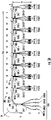
- FIG. 5C is a schematic view of another embodiment of a preconnectorized distribution cable assembly 300" illustrating multiple distribution tethers 324" and multiple tap tethers 326". Such configurations may be used to increase fiber density and/or for certain routing configurations, such as by routing each distribution tether 324" to each tap tether 326".
- the distribution connectors 308(1)-308(12) of the distribution tethers 324" are in optical communication with the tap connectors 314(1)-314(2) of the tap tethers 326".
- tap connectors 314, 314' and distribution connectors 308 are shown as MTP connectors. However, it is within the scope of the present disclosure that alternate connectors may be used, such as SC or LC, for example.
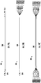
- tap connectors 314, 314' and distribution connectors 308 are the same types of connectors as shown in FIGS. 9A and 9C .
- tap connectors 314, 314' and distribution connectors 308 are different types of connectors as shown in FIG. 9B .
- tap connectors 314, 314' and distribution connectors 308 are each different types of connectors.
- individual connectors of tap connectors 314, 314' are different.
- individual connectors of distribution connectors 308 are each different types of connectors.
- distribution cable 200 is inserted into a half 327A of main passage 327 of first half 321 of tap point 320. Then, a subunit cable 204 housed within distribution cable 200 is extracted through perforation 205 of distribution cable 200, and the extracted subunit cable 204 is fed into a portion 329A of drop cable passage 329. Then, a second half 323 of tap point 320 is coupled to first half 321 of tap point 320 to assemble tap point assembly 350 onto distribution cable assembly 300.
- a pulling grip 330 is provided on distribution cable 200 as shown in FIG. 9 .
- pulling grip 330 is provided between distribution end 310 and tap cables 312, and pulling grip 330 provides a handle 332 onto which a user can grab and apply a pulling force to move distribution cable 300 through data center 100,100'.
- pulling grip 330 is made of a heat shrink material.
- pulling grip 330 can be made of other suitable materials such as a hot melt resin resulting from a low pressure molding process, for example.
- pulling grip 330 provides a pulling force ranging between about 150 N and 200 N for the heat shrink material or between about 400 N to about 450 N for the low pressure molded hot melt resin.
Landscapes
- Physics & Mathematics (AREA)
- General Physics & Mathematics (AREA)
- Optics & Photonics (AREA)
- Light Guides In General And Applications Therefor (AREA)
- Connector Housings Or Holding Contact Members (AREA)
Abstract
Description
- This application claims the benefit of priority of International Application No.
PCT/CN21/90996, filed on April 29, 2021 , the content of which is relied upon and incorporated herein by reference in its entirety. - This disclosure relates to preconnectorized optical distribution cable assemblies, and in particular, relates to preconnectorized optical distribution cable assemblies design and deployment capability.
- Data center design and cabling-infrastructure architecture are increasingly large and complex, which requires incorporation of high-density optical components (e.g., optical fiber densities), such as to compensate for limited space and meet increasing performance demands. Many data centers include fiber optic cables, which have a number of advantages in waveguide systems compared to bulky traditional conductor cables (e.g., copper). Fiber optic cables provide wide bandwidth data transmission, transport multiple signals and traffic types, and/or deliver high-speed Internet access, especially as data rates increase. Data centers utilize multi-fiber cables to interconnect and provide signals between building distribution frames and/or to individual unit centers (e.g., computer servers). However, the labor and cost of deploying such multi-fiber cable networks for a data center can be high. Thus, there is a desire to reduce the time and costs associated with data center construction, particularly regarding cabling installation.
- One way to improve optical infrastructure installation efficiency is to pre-engineer infrastructure components. Such components (e.g., fiber optic cables) may be preterminated in a factory with connectors installed, tested, and packaged for fast, easy, and safe installation at a data center. In this way, the installer merely needs to unpack the components, pull or route the preconnectorized fiber optic cable assembly, snap-in connectors, and/or install patch cords to end equipment, etc. This saves a significant amount of time, effort, and costs compared to on-site connectorization and assembly of cables.
- However, data center configurations vary, and there is a need to improve upon the flexibility of the infrastructure components to accommodate different data center configurations. Stated another way, a need remains in the art to continue to improve upon installation efficiency of the infrastructure components to accommodate different data center configurations.
- The present disclosure relates to a distribution cable assembly that has various features to enable flexible configurations to accommodate various data center configurations.
- In one embodiment, a distribution cable assembly is provided. The distribution cable assembly, comprising: a distribution cable having a distribution end and a plurality of subunit cables within the distribution cable; a plurality of tap points positioned along a length of the distribution cable, wherein the plurality of tap points are each configured to route one of the plurality of subunit cables away from a remainder of the plurality of subunit cables to form a respective tap cable and the plurality of tap points are spaced apart in a first configuration; wherein the plurality of tap points are adjustable such that the plurality of tap points are spaced apart in a second configuration that is different than the first configuration.
- In an alternate embodiment, the plurality of tap points are adjustable such that a first quantity of the plurality of tap points is changed to a second quantity of the plurality of tap points, wherein the second quantity is different than the first quantity. In an alternate embodiment, each tap point of the plurality of tap points comprises a first half and a second half, wherein the first half and the second half couple to each other in a snap fit configuration to define a main passage and a drop cable passage separated by an interior wall. In an alternate embodiment, each tap point of the plurality of tap points includes a first aperture, a second aperture, and a third aperture wherein the first aperture and the second aperture define the main passage, and wherein the third aperture and the interior wall define the drop cable passage. In an alternate embodiment, the distribution cable assembly further including a first grommet applied onto edges of the first aperture and a second grommet applied onto edges of the second aperture. In an alternate embodiment, the distribution cable assembly further including a third grommet applied onto edges of the third aperture. In an alternate embodiment, the distribution cable assembly further including a boot assembly extending through the third aperture and into the drop cable passage. In an alternate embodiment, each tap point of the plurality of tap points routes a respective subunit cable to form a respective a tap cable, and wherein each tap cable has a respective length. In an alternate embodiment, at least one of the respective lengths of the tap cables are different with respect to the respective length of another tap cable. In an alternate embodiment, the distribution cable assembly further comprises: a pulling grip positioned between the distribution end and the plurality of tap points. In an alternate embodiment, the distribution cable comprises a mesh material having perforations through which at least one subunit cable of the plurality of subunit cables is fed through.
- In one embodiment, a tap point assembly is provided. The tap point assembly comprising: a tap point comprising: a first half; a second half coupled to the first half in a snap fit configuration to define an interior of the tap point; a main passage defined by the first half and the second half, wherein the main passage terminates at a first aperture and a second aperture; an interior wall within the interior of the tap point, the interior wall defining a drop cable passage terminating at a third aperture; a distribution cable seated in the main passage from the first aperture to the second aperture, wherein the distribution cable includes at least one subunit cable within an interior of the distribution cable; and a tap cable exiting the third aperture of the tap point, wherein the tap cable is formed by a subunit cable of the at least one subunit cable that is extracted from the distribution cable and seated within the drop cable passage.
- In an alternate embodiment, wherein the tap point assembly is movable along a longitudinal axis of the distribution cable. In an alternate embodiment, the distribution cable comprises a mesh material and having a perforation through which the subunit cable that forms the tap cable is extracted. In an alternate embodiment, the tap point assembly further including a first grommet applied onto edges of the first aperture and a second grommet applied onto edges of the second aperture. In an alternate embodiment, the tap point assembly further including a third grommet applied onto edges of the third aperture. In an alternate embodiment, the distribution cable assembly further including a boot assembly extending through the third aperture and into the drop cable passage. In an alternate embodiment, the drop cable passage includes a wall with a recess, and wherein the wall is substantially perpendicular to the interior wall. In an alternate embodiment, the recess of the wall is configured to hold a portion of the boot assembly.
- In one embodiment, a method of assembling a distribution cable assembly is provided. The method of assembling a distribution cable assembly comprising: inserting a distribution cable into a first half of a tap point, wherein the distribution cable is seated in a portion of a main passage; removing a subunit cable from the distribution cable; feeding the extracted subunit cable into a portion of a drop cable passage; and coupling a second half of the tap point onto the first half of the tap point in a snap fit configuration.
- Additional features and advantages will be set out in the detailed description which follows, and in part will be readily apparent to those skilled in the technical field of optical connectivity. It is to be understood that the foregoing general description, the following detailed description, and the accompanying drawings are merely exemplary and intended to provide an overview or framework to understand the nature and character of the claims.
- The accompanying drawings are included to provide a further understanding, and are incorporated in and constitute a part of this specification. The drawings illustrate one or more embodiment(s), and together with the description serve to explain principles and operation of the various embodiments. Features and attributes associated with any of the embodiments shown or described may be applied to other embodiments shown, described, or appreciated based on this disclosure.
-
FIG. 1 is a schematic of a data center; -
FIG. 2 is a schematic of an alternate embodiment of the data center ofFIG.1 ; -
FIG. 3A is a perspective view of a section of fiber optic distribution cable, in accordance with aspects of the present disclosure; -
FIG. 3B is a perspective view of a section of a subunit cable of the distribution cable ofFIG. 3A , in accordance with aspects of the present disclosure; -
FIG. 3C is a cross-sectional view of an embodiment of the distribution cable ofFIGS. 3A-3B , in accordance with aspects of the present disclosure; -
FIG. 3D is a perspective view of a distribution cable and interior subunit cables in accordance with the present disclosure; -
FIG. 4 is a cross-sectional view of another embodiment of the distribution cable ofFIGS. 3A-3B , in accordance with aspects of the present disclosure; -
FIG. 5A is a schematic view of an embodiment of a preconnectorized distribution cable assembly, including the distribution cable ofFIGS. 3A-4B and illustrating a distribution tether with MPO connectors and eight subunit cables with MPO connectors. -
FIG. 5B is a schematic view of another embodiment of a preconnectorized distribution cable assembly, including the distribution cable ofFIGS. 3A-4 and illustrating a distribution tether with MTP connectors and eight tether subunits with LC uniboot connectors. -
FIG. 5C is a schematic view of another embodiment of a preconnectorized distribution cable assembly, including the distribution cable ofFIGS. 3A-4B and illustrating multiple distribution tethers and multiple tap tethers. -
FIG. 6A is an exploded perspective view of a tap point in accordance with the present disclosure; -
FIG. 6B is a top view of the tap point ofFIG. 6A illustrating an interior of the tap point ofFIG. 6A ; -
FIG. 6C is a top view of a half of a tap point assembly in accordance with the present disclosure; -
FIG. 6D is a perspective view of the tap point assembly ofFIG. 6C as assembled; -
FIG. 7A is a perspective view of an alternate embodiment of the tap point assembly ofFIG. 6D ; -
FIG. 7B is a partial exploded view of the tap point assembly ofFIG. 7A ; -
FIG. 8 is a perspective view of a pulling grip in accordance with the present disclosure; -
FIGS. 9A-9C are schematic illustrations of distribution cables in accordance with the present disclosure; and -
FIGS. 10A-10B are schematic illustrations of distribution cable assemblies in accordance with the present disclosure. - Various embodiments will be further clarified by examples in the description below. In general, the description relates to a distribution cable assembly that has various features to enable flexible configurations to accommodate various data center configurations.
- Referring first to
FIG. 1 , a schematic of adata center 100 is shown. As shown,data center 100 includes adistribution frame region 101 and acage region 103.Distribution frame region 101 includes amain distribution frame 105 that is connected tocage region 103 as discussed herein. In particular, as shown inFIG. 1 , a main distribution frame (MDF) 105 is connected to an intermediate distribution frame (IDF) 107. Intermediate distribution frames are connected to individual cabinets orservers 109 in one or more nearby rows of equipment racks withincage region 103. - Referring now to
FIG. 2 , an alternate configuration of a data center 100' is shown. Data center 100' includes distribution frame regions 101' that each include main distribution frames 105' that are separated from each other and from cage region 103'. As shown, main distribution frames 105' are connected to information distribution frames 106, each of which are connected to each other and corresponding cage regions 103'. - To connect the above-mentioned units to each other, distribution cables are used throughout
data center 100, 100'. -
FIGS. 3A-3B are views of a section of anexample distribution cable 200, in accordance with aspects of the present disclosure. Referring toFIG. 3A , thedistribution cable 200 includes a cable bundle 202 (may also be referred to herein as a cable core) of a plurality ofsubunit cables 204 and a distribution jacket 206 (may also be referred to as outer jacket, subunit jacket, etc.) defining adistribution interior 208. Thecable bundle 202 of thesubunit cables 204 is disposed in thedistribution interior 208 of thedistribution jacket 206. - In certain embodiments, a strain-
relief component 210 may be disposed within thedistribution interior 208 of thedistribution jacket 206 between thecable bundle 202 of thesubunit cables 204 and thedistribution jacket 206. The strain-relief component 210 surrounds and/or is interspersed among thecable bundle 202 of thesubunit cables 204. - In certain embodiments, an outer layer of a plurality of
subunit cables 204 is stranded around an inner layer ofsubunit cables 204 to provide higher fiber densities. This reduces any stress or strain concentrations on any single subunit cable 204 (e.g., from bending of the distribution cable 200). In certain embodiments, a central strength element (not shown) may be provided, and thesubunit cables 204 may be stranded around the central strength element. In yet other cable applications, stranding may not be used and thesubunit cables 204 may run substantially parallel through thedistribution cable 200. - Referring to
FIG. 3B , each subunit cable 204 (may also be referred to herein as a micro module, etc.) includes a subunit bundle 212 (may also be referred to herein as a subunit core) of a plurality of tether cables 214 (may also be referred to herein as tether subunits) and asubunit jacket 216 defining asubunit interior 218. Thesubunit bundle 212 of thetether cable 214 is disposed in thesubunit interior 218 of thesubunit jacket 216. - In certain embodiments, a strain-
relief component 220 may be disposed within thesubunit interior 218 of thesubunit jacket 216 between thesubunit bundle 212 of thetether cables 214 and thesubunit jacket 216. The strain-relief component 220 surrounds and/or is interspersed among thesubunit bundle 212 of thesubunit cables 204. In certain embodiments, the strain-relief component 220 may be, for example, a layer of longitudinally-extending yarns for absorbing tensile loads on thesubunit bundle 212. In certain embodiments, the strain-relief component 220 includes a dispersed layer of aramid strands in the region between thesubunit jacket 216 and thesubunit bundle 212 oftether cables 214. - In certain embodiments, a
central strength element 222 may be disposed in a center of thesubunit bundle 212, and thereby, within thesubunit interior 218 of thesubunit jacket 216. Thetether cables 214 may be stranded (e.g., helically twisted) around thecentral strength element 222. In certain embodiments, an outer layer of a plurality oftether cables 214 is stranded around an inner layer oftether cables 214 to provide higher fiber densities. In yet other cable applications, stranding may not be used and thetether cables 214 may run substantially parallel through thesubunit cable 204. Thecentral strength element 222 provides strain-relief and absorbs loads from thetether cables 214. - In certain embodiments, as illustrated, the
subunit bundle 212 is stranded such that thetether cables 214 are helically twisted around a longitudinal axis of thesubunit bundle 212. This reduces any stress or strain concentrations on any one tether cable 214 (e.g., from bending of thedistribution cable 200 and/or subunit cable 204). Eachtether cable 214 includes one or more optical fibers 224 (may also be referred to herein as optical fiber waveguides). - In certain embodiments, the strain-
relief component 210 and/or strain-relief component 220 may utilize tensile yarns as tension relief elements that provide tensile strength to thecables - Referring briefly to
FIG. 3D , an embodiment ofdistribution cable 200 is shown in accordance with aspects of the present disclosure. As shown inFIG. 3D ,distribution cable 200 includes adistribution jacket 206 that definesdistribution interior 208 in which acable bundle 202 of a plurality ofsubunit cables 204 are housed. Also, as shown,distribution cable 200 does not includestrain relief component 210 thereby allowing direct access to the plurality ofsubunit cables 204 beneathdistribution jacket 206 as discussed below.Distribution cable 200 is made of a mesh material that is wrapped around plurality ofsubunit cables 204. Advantageously, the mesh material ofdistribution cable 200 provides flexibility todistribution cable 200 such thatdistribution cable 200 can accommodate different numbers of subunit cables depending on application and cabling requirements. Additionally,distribution cable 200 has aperforation 205 upon whichdistribution cable 200 can be opened as shown inFIG. 3D to accesssubunit cables 204 and to route one ofsubunit cables 204 within tap point 320 (FIG. 6C ) as discussed below. Moreover, the mesh material ofdistribution cable 200 can be various colors, which can assist in field installation. For example, different colors could identify different information distribution frames 107 orcabinets 109 to whichdistribution cable 200 is associated. -
FIG. 3C is a cross-sectional view of an embodiment of a distribution cable 200' ofFIGS. 3A-3B , in accordance with aspects of the present disclosure. Each of the subunit cables 204' includesoptical fibers 224 loosely disposed within the subunit cable 204' (e.g., in an essentially parallel array). The subunit cable 204' may be further encased in an interlocking armor for enhanced crush resistance. -
FIG. 4 is a cross-sectional view of another embodiment of adistribution cable 200". Each of thesubunit cables 204" of thecable bundle 202" is astack 201 offiber ribbons 203. Eachfiber ribbon 203 includes a plurality ofoptical fibers 224. -
FIGS. 5A-5C are embodiments of adistribution cable assembly 300 incorporating the distribution cable ofFIGS. 3A-3D . Referring toFIG. 5A , thedistribution cable assembly 300 includes a distribution subunit 302 (may also be referred to herein as a main subassembly) and a plurality of tap subunits 304(1)-304(8) (may also be referred to herein as a branch subassembly, drop subunit, etc.). Thedistribution subunit 302 includes a distribution cable 200 (may be referred to as a distribution cable portion) anddistribution connectors 308 at a distribution end 310 (may also be referred to herein as upstream end). Each of the plurality of tap subunits 304(1)-304(8) includes a tap cable 312(1)-312(8) (may also be referred to herein as a drop cable or tap cable portion) and tap connectors 314(1)-314(8) at a tap end 316(1)-316(8) (may also be referred to herein as downstream end). In certain embodiments,subunit cables 204 extend from thedistribution connector 308 to respectively one of the plurality of tap connectors 314(1)-314(8), each at a different tap point 320(1)-320(8) (may also be referred to herein as drop point, terminated access point, etc.) along a length of thedistribution cable 200. For example,subunit cable 204 extends from thedistribution connector 308 through thedistribution cable 200 to the tap connector 314(2). The spacing S1-S7 between tap points 320(1)-320(8) depends on the application and cabling requirements and can be adjusted as described below. - Referring briefly to
FIGS. 6A-6D , atap point 320 and atap point assembly 350 respectively are shown.Tap point 320 is configured to routedistribution cable 200 throughtap point 320 such that asubunit cable 204 can be extracted from distribution cable 200 (through perforation 205) and routed throughtap point 320 to form a drop cable ortap cable 312 as shown inFIG. 6C . As shown,tap point 320 comprises afirst half 321 and asecond half 323 that couple to each other to define an interior 325. In some embodiments,first half 321 andsecond half 323 are coupled to each other by corresponding latch 337 and grooves 339 provided onfirst half 321 andsecond half 323 that fit in a snap fit configuration. However, it is within the scope of the present disclosure that alternate coupling methods may be used. Advantageously, the snap fit oftap point 320 enables mobility oftap point 320 along a longitudinal axis A ofdistribution cable 200 which enables flexibility in cable installation onto a server or information data frame in a cage region of a data center. For example, ifcabinets 109 are spaced apart a greater distance than anticipated, halves 321, 323 of tap points 320 are decoupled and moved along longitudinal axis A ofdistribution cable 200 to increase or decrease spacings S1-S7 between tap points 320 such that the spacing between tap points 320 can accommodate the corresponding distance/spacing betweencabinets 109 incage region 103. In some embodiments, spacing S1-S7 ranges between 600 mm and 800 mm. Advantageously, the spacing S1-S7 can be adjusted in accordance to customer requirements such that in some embodiments, spacing S1-S7 can be greater than or equal to 600 mm or less than or equal to 600 mm. In addition, the number of tap points 320 ondistribution cable assembly 300 can be adjusted based on the application and cabling requirements. In particular, the snap fit configuration oftap point 320 enables easy addition and removal of tap points alongdistribution cable 200 to accommodate various data center configurations during installation. In some embodiments,distribution cable assembly 300 has a number of tap points 320 ranging between 1 and 10, or between 6 and 8. Advantageously, similar to spacing S1-S7, the number of tap points 320 can be adjusted in accordance to customer requirements such that in some embodiments, the number of tap points 320 can be outside the stated ranges above. - In some embodiments,
tap point 320 is made of a plastic material such as polycarbonate (PC) + acrylonitrile butadiene styrene (ABS) or polyetherimide (e.g., ULTEM®) or polyethersulfone (PESU). However, it is contemplated that in alternate embodiments, alternate materials may be used, such as metal for example. -
Interior 325 comprises amain passage 327 and adrop cable passage 329.Main passage 327 is defined betweenaperture 331 andaperture 333 oftap point 320 and is configured to receive and allowdistribution cable 200 to pass throughtap point 320. That is,main passage 327 has a width that corresponds to a width ofdistribution cable 200 such thatdistribution cable 200 can be seated withinmain passage 327. - As shown in
FIG. 6C ,tap point assembly 350 comprisestap point 320 wheredistribution cable 200 is seated withinmain passage 327, andsubunit cable 204 is extracted from distribution cable 200 (through perforation 205) and inserted into and throughdrop cable passage 329. - Drop
cable passage 329 is an off shoot ofmain passage 327 and is defined byinterior wall 328, which physically separatesmain passage 327 fromdrop cable passage 329 and provides structural reinforcement ontotap point 320 anddistribution cable 200. Dropcable passage 329 leads toaperture 335 wheretap cable 312 exits tappoint 320. In some embodiments, as shown, awall 351 is provided with arecess 353 wherewall 351 is substantially perpendicular tointerior wall 328, andwall 351 dividesdrop cable passage 329 into at least aportion 329A as described below.Recess 353 provides a mounting surface fortap cable 312 to rest withindrop cable passage 329. In some embodiments,recess 353 provides a mounting surface to which a strain relief structure (e.g., aboot assembly 347,FIG. 7B ) can engage as discussed below. - Referring now to
FIGS. 7A and 7B , in some embodiments,tap point 320 includesgrommets apertures distribution cable 200 andcorresponding tap cable 312. Similarly, in an alternate embodiment, as shown in FIGS. 8A and 8B,tap point 320 includesgrommets apertures distribution cable 200. However, as shown,subunit cable 204 andtap cable 312 are provided with aboot assembly 347 that inserts throughaperture 335 and intodrop cable passage 329. As shown,boot assembly 347 extends intodrop cable passage 329 and engages with the mounting surface provided byrecess 353 ofwall 351 thereby holdingtap cable 312 in place with limited mobility. In some embodiments,boot assembly 347 extends intodrop cable passage 329 and engages withinterior wall 328 and aside wall 349 oftap point 320 to holdtap cable 312 in place with limited mobility.Boot assembly 347 is configured to provide strain relief and improved retention (i.e., improved retention force) ontosubunit cable 204 andtap cable 312 exitingtap point 320. In alternate embodiments, a heat shrink material may be used to provide similar strain relief asboot assembly 347. In some embodiments,grommets - Referring back to
FIG. 5A , distribution connectors 308(1)-308(8) are in optical communication with the tap connectors 314(1)-314(8) (may be referred to generally as tap connectors 314), where thedistribution cable assembly 300 is pre-connectorized, such as for connection to a patch panel (e.g., at intermediate distribution frame 105). Thedistribution cable assembly 300 includes adistribution portion 317 of thesubunit cable 204 that extends for a predetermined length S0 from the distribution connectors 308(1)-308(8) through thedistribution cable 200 to thefirst tap portion 318. Thedistribution cable assembly 300 further includestap portions 318 of thesubunit cable 204 that extend from thedistribution cable 200 to the tap connectors 314(1)-314(8). Accordingly, the total length Stot of thedistribution cable 200 includes S0-S7. - In certain embodiments, as illustrated in
FIG. 5A , thedistribution subunit 302 includes a distribution tether 324 (may be referred to as a distribution tether portion) at thedistribution end 310. In certain embodiments, thedistribution cable assembly 300 includesmultiple distribution tethers 324 and multiple tap tethers. Thedistribution tether 324 may be pre-connectorized and extend a predetermined length L1 from anend 325 of thedistribution jacket 106. Further, thedistribution tether 324 includes distribution connectors 308(1)-308(8) coupled to ends of thedistribution tether 324. Similarly, the tap subunits 304(1)-304(8) are pre-connectorized such that the tap cables 312(1)-312(8) extend a predetermined length L2 from thedistribution jacket 106. Further, the tap subunits 304(1)-304(8) include tap connectors 314(1)-314(8) coupled to tap ends 316(1)-316(8) of the tap subunits 304(1)-304(8). In some embodiments, length L1 and length L2 can be the same length. In some embodiments, lengths L2 are the same length amongtap connectors 314 as shown inFIGS. 10A and 10B . In alternate embodiments, lengths L1, L2 are different. In some embodiments, lengths L1 amongdistribution tethers 324 vary as shown inFIGS. 5C and10B . Stated another way, lengths L1 among tap cables 312(1)- 312(8) may vary depending on the application and cabling requirements. In some embodiments, lengths L2 among tap cables 312(1)-312(8) vary. Stated another way, lengths L2 among tap cables 312(1)- 312(8) may vary depending on the application and cabling requirements. For example, length L2 of tap cable 312(1) may be different than length L2 of tap cable 312(2)-312(8). Such variability of lengths L2 enablesdistribution cable assembly 300 to have flexibility in application depending on the configuration ofdata center 100, 100'. In some embodiments, length L2 has a length ranging between about 100 mm and about 300 mm. Advantageously, similar to spacing S1-S7 and number of tap points 320, lengths L1 and L2 can be adjusted or modified in accordance todata center 100, 100' construction specifications (i.e., height and size ofdata centers 100, 100') such that lengths L1 and L2 can be greater than or less than the stated ranges above. - In certain embodiments, as illustrated in
FIG. 5B , thedistribution cable assembly 300' includes the distribution subunit 302' with a distribution tether 324' at thedistribution end 310, which is pre-connectorized. Further, the tap subunits 304'(1)-304'(8) includes tap tethers 326'(1)-326'(8) at the tap ends 316'(1)-316'(8), which is pre-connectorized with tap connectors 314'(1)-314'(8). -
FIG. 5C is a schematic view of another embodiment of a preconnectorizeddistribution cable assembly 300" illustratingmultiple distribution tethers 324" andmultiple tap tethers 326". Such configurations may be used to increase fiber density and/or for certain routing configurations, such as by routing eachdistribution tether 324" to eachtap tether 326". The distribution connectors 308(1)-308(12) of the distribution tethers 324" are in optical communication with the tap connectors 314(1)-314(2) of the tap tethers 326". - As shown in
FIGS. 5A-5C , tapconnectors 314, 314' anddistribution connectors 308 are shown as MTP connectors. However, it is within the scope of the present disclosure that alternate connectors may be used, such as SC or LC, for example. In some embodiments, tapconnectors 314, 314' anddistribution connectors 308 are the same types of connectors as shown inFIGS. 9A and 9C . In some embodiments, tapconnectors 314, 314' anddistribution connectors 308 are different types of connectors as shown inFIG. 9B . In other embodiments, tapconnectors 314, 314' anddistribution connectors 308 are each different types of connectors. In another embodiment, individual connectors oftap connectors 314, 314' are different. In another embodiment, individual connectors ofdistribution connectors 308 are each different types of connectors. - To assemble
distribution cable assembly 300,distribution cable 200 is inserted into a half 327A ofmain passage 327 offirst half 321 oftap point 320. Then, asubunit cable 204 housed withindistribution cable 200 is extracted throughperforation 205 ofdistribution cable 200, and the extractedsubunit cable 204 is fed into aportion 329A ofdrop cable passage 329. Then, asecond half 323 oftap point 320 is coupled tofirst half 321 oftap point 320 to assembletap point assembly 350 ontodistribution cable assembly 300. - To move
distribution cable assembly 300 throughoutdata center 100, 100', a pullinggrip 330 is provided ondistribution cable 200 as shown inFIG. 9 . In particular, pullinggrip 330 is provided betweendistribution end 310 and tapcables 312, and pullinggrip 330 provides ahandle 332 onto which a user can grab and apply a pulling force to movedistribution cable 300 through data center 100,100'. In some embodiments, pullinggrip 330 is made of a heat shrink material. However, it is within the scope of the present disclosure that pullinggrip 330 can be made of other suitable materials such as a hot melt resin resulting from a low pressure molding process, for example. In some embodiments, pullinggrip 330 provides a pulling force ranging between about 150 N and 200 N for the heat shrink material or between about 400 N to about 450 N for the low pressure molded hot melt resin. - There are many other alternatives and variations that will be appreciated by persons skilled in optical connectivity without departing from the spirit or scope of this disclosure. For at least this reason, the invention should be construed to include everything within the scope of the appended claims and their equivalents.
Claims (15)
- A distribution cable assembly, comprising:a distribution cable having a distribution end and a plurality of subunit cables within the distribution cable;a plurality of tap points positioned along a length of the distribution cable, wherein the plurality of tap points are each configured to route one of the plurality of subunit cables away from a remainder of the plurality of subunit cables to form a respective tap cable and the plurality of tap points are spaced apart in a first configuration;
wherein the pluarlity of tap points are adjustable such that the plurality of tap points are spaced apart in a second configuration that is different than the first configuration. - The distribution cable assembly of claim 1, wherein the plurality of tap points are adjustable such that a first quantity of the plurality of tap points is changed to a second quantity of the plurality of tap points, wherein the second quantity is different than the first quantity.
- The distribution cable assembly of claim 1 or claim 2, wherein each tap point of the plurality of tap points comprises a first half and a second half, wherein the first half and the scond half couple to each other in a snap fit configuration to define a main passage and a drop cable passage separated by an interior wall.
- The distribution cable assembly of claim 3, wherein each tap point of the plurality of tap points includes a first aperture, a second aperture, and a third aperture wherein the first aperture and the second aperture define the main passage, and wherein the third aperture and the interior wall define the drop cable passage.
- The distribution cable assembly of claim 4, further including a first grommet applied onto edges of the first aperture and a second grommet applied onto edges of the second aperture.
- The distribution cable assembly of claim 5, further including a third grommet applied onto edges of the third aperture.
- The distribution cable assembly of any of claims 4-6, further including a boot assembly extending through the third aperture and into the drop cable passage.
- The distribution cable assembly of any of claims 1-7, wherein each tap point of the plurality of tap points routes a respective subunit cable to form a respective a tap cable, and wherein each tap cable has a respective length.
- The distribution cable assembly of claim 8, wherein at least one of the respective lengths of the tap cables are different with respect to the respective length of another tap cable.
- The distribution cable of any of claims 1-9, wherein the distribution cable assembly further comprises:
a pulling grip positioned between the distribution end and the plurality of tap points. - The distribution cable assembly of any of claims 1-10, wherein the distribution cable comprises a mesh material having perforations through which at least one subunit cable of the plurality of subunit cables is fed through.
- The tap point assembly of any of claims 1-11, wherein the plurality of tap points are movable along a longitudinal axis of the distribution cable.
- The distribution cable assembly of any of claims 3-12, wherein the drop cable passage includes a wall with a recess, and wherein the wall is substantially perpendicular to the interior wall.
- The distribution cable assembly of claim 13, wherein the recess of the wall is configured to hold a portion of the boot assembly.
- A method of assembling a distribution cable assembly comprising:inserting a distribution cable into a first half of a tap point, wherein the distribution cable is seated in a portion of a main passage;removing a subunit cable from the distribution cable;feeding the extracted subunit cable into a portion of a drop cable passage; andcoupling a second half of the tap point onto the first half of the tap point in a snap fit configuration.
Applications Claiming Priority (1)
| Application Number | Priority Date | Filing Date | Title |
|---|---|---|---|
| PCT/CN2021/090996 WO2022226895A1 (en) | 2021-04-29 | 2021-04-29 | Preconnectorized optical distribution cable assemblies and corresponding methods of deployment |
Publications (2)
| Publication Number | Publication Date |
|---|---|
| EP4089458A2 true EP4089458A2 (en) | 2022-11-16 |
| EP4089458A3 EP4089458A3 (en) | 2022-11-23 |
Family
ID=81389097
Family Applications (1)
| Application Number | Title | Priority Date | Filing Date |
|---|---|---|---|
| EP22170279.8A Pending EP4089458A3 (en) | 2021-04-29 | 2022-04-27 | Preconnectorized optical distribution cable assemblies and corresponding methods of deployment |
Country Status (3)
| Country | Link |
|---|---|
| US (1) | US11880082B2 (en) |
| EP (1) | EP4089458A3 (en) |
| WO (1) | WO2022226895A1 (en) |
Families Citing this family (2)
| Publication number | Priority date | Publication date | Assignee | Title |
|---|---|---|---|---|
| US20240118498A1 (en) * | 2021-04-29 | 2024-04-11 | Corning Research & Development Corporation | Preconnectorized optical distribution cable assemblies and corresponding methods of deployment |
| US12069832B2 (en) * | 2022-11-15 | 2024-08-20 | Corning Research & Development Corporation | Bundled cable assembly |
Citations (1)
| Publication number | Priority date | Publication date | Assignee | Title |
|---|---|---|---|---|
| US20100150504A1 (en) * | 2008-12-11 | 2010-06-17 | Tyco Electronics Corporation | Fiber optic multi dwelling unit deployment appartus and methods for using the same |
Family Cites Families (30)
| Publication number | Priority date | Publication date | Assignee | Title |
|---|---|---|---|---|
| WO1981001343A1 (en) | 1979-11-02 | 1981-05-14 | Mitsubishi Electric Corp | Wiring harness |
| JPS63173008A (en) | 1987-01-13 | 1988-07-16 | Mitsubishi Heavy Ind Ltd | Optical fiber harness |
| US5335349A (en) * | 1992-12-14 | 1994-08-02 | Telect, Inc. | Telecommunication overhead cable distribution assembly |
| JP3457206B2 (en) | 1999-03-09 | 2003-10-14 | 大崎電気工業株式会社 | Optical fiber cable laying structure |
| DE19918212A1 (en) | 1999-04-22 | 2000-11-09 | Cad Cabel Inh Peter Hanzel | Cables for wiring electrical devices of a complex, individual system and process for their manufacture |
| JP4053202B2 (en) | 1999-08-11 | 2008-02-27 | トヨクニ電線株式会社 | Optical communication trunk cable branch and optical communication trunk cable |
| US7588216B1 (en) | 2001-03-19 | 2009-09-15 | Cisco Technology, Inc. | Fiber optic cabling management using hook and loop fabric |
| US6522814B2 (en) | 2001-06-05 | 2003-02-18 | Toyokuni Electric Cable Co., Ltd. | Wiring of optical communication cable to buildings |
| US7049523B2 (en) | 2002-08-30 | 2006-05-23 | Belden Technologies, Inc. | Separable multi-member composite cable |
| US7006739B2 (en) | 2003-12-15 | 2006-02-28 | Corning Cable Systems Llc | Pre-connectorized fiber optic distribution cable |
| US7272284B1 (en) | 2004-01-29 | 2007-09-18 | Honeywell International Inc. | Bundled cables and method of making the same |
| US7266274B2 (en) * | 2004-11-03 | 2007-09-04 | Corning Cable Systems Llc | Pre-connectorized fiber optic distribution cable having overmolded access location |
| US7346243B2 (en) | 2006-05-11 | 2008-03-18 | Corning Cable Systems Llc | Methods for manufacturing fiber optic distribution cables |
| WO2008021253A2 (en) | 2006-08-14 | 2008-02-21 | Adc Telecommunications, Inc. | Factory spliced cable assembly |
| US7668432B2 (en) * | 2007-01-31 | 2010-02-23 | Tyco Electronics Corporation | Multi-drop closure systems and methods for fiber optic cabling |
| JP2008249824A (en) | 2007-03-29 | 2008-10-16 | Sumitomo Electric Ind Ltd | Optical cable |
| JP3156316U (en) | 2009-10-09 | 2009-12-24 | 西日本電線株式会社 | Branched optical / metal composite cable |
| EP2489103A2 (en) * | 2009-10-14 | 2012-08-22 | FCI Automotive Holding | Sealing device for individually shielded cable, and corresponding cable assembly |
| CN101887153B (en) | 2010-01-28 | 2012-12-26 | Ccs科技公司 | Preassembled cable and manufacturing method thereof |
| US9547144B2 (en) * | 2010-03-16 | 2017-01-17 | Corning Optical Communications LLC | Fiber optic distribution network for multiple dwelling units |
| CN201717591U (en) * | 2010-07-09 | 2011-01-19 | 河北星河通信技术有限公司 | Communication cable connector sealing protection device |
| CN201749240U (en) | 2010-08-23 | 2011-02-16 | 张磊磊 | A pre-connected optical cable |
| CN103792631A (en) | 2012-11-03 | 2014-05-14 | 西安金和光学科技有限公司 | Optical cable easy to branch |
| CN204010746U (en) | 2014-07-18 | 2014-12-10 | 南京全信传输科技股份有限公司 | Hand woven flat, flexible cable assembly |
| US20160103290A1 (en) * | 2014-09-30 | 2016-04-14 | Adc Telecommunications, Inc. | Distribution cable with bidirectional breakout locations |
| EP3018512A1 (en) | 2014-11-05 | 2016-05-11 | Corning Optical Communications LLC | Bi-directional data center architectures employing a jacketless trunk cable |
| US10790899B2 (en) * | 2017-01-12 | 2020-09-29 | Commscope Technologies Llc | Optical tapping in an indexing architecture |
| JP7341689B2 (en) * | 2019-03-20 | 2023-09-11 | 住友電気工業株式会社 | connection harness |
| WO2020214762A1 (en) * | 2019-04-16 | 2020-10-22 | Corning Research & Development Corporation | Preconnectorized cable assemblies for indoor/outdoor/datacenter applications |
| CN216160878U (en) | 2021-04-29 | 2022-04-01 | 康宁研究与开发公司 | Pre-connectorized optical distribution cable assembly and tap assembly |
-
2021
- 2021-04-29 WO PCT/CN2021/090996 patent/WO2022226895A1/en not_active Ceased
-
2022
- 2022-04-19 US US17/723,789 patent/US11880082B2/en active Active
- 2022-04-27 EP EP22170279.8A patent/EP4089458A3/en active Pending
Patent Citations (1)
| Publication number | Priority date | Publication date | Assignee | Title |
|---|---|---|---|---|
| US20100150504A1 (en) * | 2008-12-11 | 2010-06-17 | Tyco Electronics Corporation | Fiber optic multi dwelling unit deployment appartus and methods for using the same |
Also Published As
| Publication number | Publication date |
|---|---|
| WO2022226895A1 (en) | 2022-11-03 |
| EP4089458A3 (en) | 2022-11-23 |
| US11880082B2 (en) | 2024-01-23 |
| US20220350104A1 (en) | 2022-11-03 |
Similar Documents
| Publication | Publication Date | Title |
|---|---|---|
| US11703652B2 (en) | Fiber optic cable assembly with integrated shuffle and fabrication method | |
| US11740424B2 (en) | Structured fiber optic cabling system including an array of ports and orthogonally arranged jumper assemblies | |
| US9052459B2 (en) | Cable assembly and method | |
| AU2020257217B2 (en) | Preconnectorized cable assemblies for indoor/outdoor/datacenter applications | |
| US8600205B2 (en) | Optical fiber array cables and associated fiber optic cables and systems | |
| US9229187B2 (en) | Fan-out assemblies and fiber optic assemblies including fiber management structure for furcations | |
| KR20030097865A (en) | Furcation apparatus for optical fibers | |
| EP2402807B1 (en) | Fiber optic cable furcation methods and assemblies | |
| US11880082B2 (en) | Preconnectorized optical distribution cable assemblies and corresponding methods of deployment | |
| US20250224585A1 (en) | Fiber optic furcation assemblies, methods, and systems | |
| US11175465B2 (en) | Fiber management enclosure for a fiber optic connector assembly and method of use | |
| CN103250315A (en) | Strain relief device | |
| US7555181B2 (en) | Fiber optic cables having at least one tether optical fiber | |
| CN216160878U (en) | Pre-connectorized optical distribution cable assembly and tap assembly | |
| US20240118498A1 (en) | Preconnectorized optical distribution cable assemblies and corresponding methods of deployment | |
| EP2016453B1 (en) | Fiber optic distribution cables and structures therefor | |
| JP4395389B2 (en) | Optical fiber tape core protecting member and optical fiber connector ferrule connection method | |
| EP4345519A1 (en) | Fiber optic cable assembly having junction shells and method of preparing same | |
| US20070140639A1 (en) | Methods for making fiber optic cables having at least one tether optical fiber | |
| JP2002267902A (en) | Terminal structure of optical cable with connector | |
| AU2014209679B2 (en) | Cable assembly and method | |
| KR20030042650A (en) | Fan-out cord holder for optical cable | |
| Cheron et al. | Effective Solutions for Wide-Ranging Applications |
Legal Events
| Date | Code | Title | Description |
|---|---|---|---|
| PUAI | Public reference made under article 153(3) epc to a published international application that has entered the european phase |
Free format text: ORIGINAL CODE: 0009012 |
|
| STAA | Information on the status of an ep patent application or granted ep patent |
Free format text: STATUS: THE APPLICATION HAS BEEN PUBLISHED |
|
| PUAL | Search report despatched |
Free format text: ORIGINAL CODE: 0009013 |
|
| AK | Designated contracting states |
Kind code of ref document: A2 Designated state(s): AL AT BE BG CH CY CZ DE DK EE ES FI FR GB GR HR HU IE IS IT LI LT LU LV MC MK MT NL NO PL PT RO RS SE SI SK SM TR |
|
| AK | Designated contracting states |
Kind code of ref document: A3 Designated state(s): AL AT BE BG CH CY CZ DE DK EE ES FI FR GB GR HR HU IE IS IT LI LT LU LV MC MK MT NL NO PL PT RO RS SE SI SK SM TR |
|
| RIC1 | Information provided on ipc code assigned before grant |
Ipc: G02B 6/44 20060101AFI20221019BHEP |
|
| STAA | Information on the status of an ep patent application or granted ep patent |
Free format text: STATUS: REQUEST FOR EXAMINATION WAS MADE |
|
| 17P | Request for examination filed |
Effective date: 20230518 |
|
| RBV | Designated contracting states (corrected) |
Designated state(s): AL AT BE BG CH CY CZ DE DK EE ES FI FR GB GR HR HU IE IS IT LI LT LU LV MC MK MT NL NO PL PT RO RS SE SI SK SM TR |
|
| STAA | Information on the status of an ep patent application or granted ep patent |
Free format text: STATUS: EXAMINATION IS IN PROGRESS |
|
| 17Q | First examination report despatched |
Effective date: 20250515 |