EP4089426B1 - Systems and methods for phase-voltage based motor period measurement and controlled signal path fault detection - Google Patents
Systems and methods for phase-voltage based motor period measurement and controlled signal path fault detection Download PDFInfo
- Publication number
- EP4089426B1 EP4089426B1 EP22171468.6A EP22171468A EP4089426B1 EP 4089426 B1 EP4089426 B1 EP 4089426B1 EP 22171468 A EP22171468 A EP 22171468A EP 4089426 B1 EP4089426 B1 EP 4089426B1
- Authority
- EP
- European Patent Office
- Prior art keywords
- phase voltage
- voltage input
- integrated circuit
- period
- commanded
- Prior art date
- Legal status (The legal status is an assumption and is not a legal conclusion. Google has not performed a legal analysis and makes no representation as to the accuracy of the status listed.)
- Active
Links
Images



Classifications
-
- G—PHYSICS
- G01—MEASURING; TESTING
- G01R—MEASURING ELECTRIC VARIABLES; MEASURING MAGNETIC VARIABLES
- G01R31/00—Arrangements for testing electric properties; Arrangements for locating electric faults; Arrangements for electrical testing characterised by what is being tested not provided for elsewhere
- G01R31/34—Testing dynamo-electric machines
- G01R31/343—Testing dynamo-electric machines in operation
-
- H—ELECTRICITY
- H02—GENERATION; CONVERSION OR DISTRIBUTION OF ELECTRIC POWER
- H02P—CONTROL OR REGULATION OF ELECTRIC MOTORS, ELECTRIC GENERATORS OR DYNAMO-ELECTRIC CONVERTERS; CONTROLLING TRANSFORMERS, REACTORS OR CHOKE COILS
- H02P6/00—Arrangements for controlling synchronous motors or other dynamo-electric motors using electronic commutation dependent on the rotor position; Electronic commutators therefor
- H02P6/14—Electronic commutators
- H02P6/16—Circuit arrangements for detecting position
- H02P6/18—Circuit arrangements for detecting position without separate position detecting elements
- H02P6/186—Circuit arrangements for detecting position without separate position detecting elements using difference of inductance or reluctance between the phases
-
- B—PERFORMING OPERATIONS; TRANSPORTING
- B60—VEHICLES IN GENERAL
- B60L—PROPULSION OF ELECTRICALLY-PROPELLED VEHICLES; SUPPLYING ELECTRIC POWER FOR AUXILIARY EQUIPMENT OF ELECTRICALLY-PROPELLED VEHICLES; ELECTRODYNAMIC BRAKE SYSTEMS FOR VEHICLES IN GENERAL; MAGNETIC SUSPENSION OR LEVITATION FOR VEHICLES; MONITORING OPERATING VARIABLES OF ELECTRICALLY-PROPELLED VEHICLES; ELECTRIC SAFETY DEVICES FOR ELECTRICALLY-PROPELLED VEHICLES
- B60L3/00—Electric devices on electrically-propelled vehicles for safety purposes; Monitoring operating variables, e.g. speed, deceleration or energy consumption
- B60L3/0023—Detecting, eliminating, remedying or compensating for drive train abnormalities, e.g. failures within the drive train
- B60L3/0061—Detecting, eliminating, remedying or compensating for drive train abnormalities, e.g. failures within the drive train relating to electrical machines
-
- B—PERFORMING OPERATIONS; TRANSPORTING
- B60—VEHICLES IN GENERAL
- B60R—VEHICLES, VEHICLE FITTINGS, OR VEHICLE PARTS, NOT OTHERWISE PROVIDED FOR
- B60R16/00—Electric or fluid circuits specially adapted for vehicles and not otherwise provided for; Arrangement of elements of electric or fluid circuits specially adapted for vehicles and not otherwise provided for
- B60R16/02—Electric or fluid circuits specially adapted for vehicles and not otherwise provided for; Arrangement of elements of electric or fluid circuits specially adapted for vehicles and not otherwise provided for electric constitutive elements
- B60R16/023—Electric or fluid circuits specially adapted for vehicles and not otherwise provided for; Arrangement of elements of electric or fluid circuits specially adapted for vehicles and not otherwise provided for electric constitutive elements for transmission of signals between vehicle parts or subsystems
-
- G—PHYSICS
- G01—MEASURING; TESTING
- G01R—MEASURING ELECTRIC VARIABLES; MEASURING MAGNETIC VARIABLES
- G01R19/00—Arrangements for measuring currents or voltages or for indicating presence or sign thereof
- G01R19/25—Arrangements for measuring currents or voltages or for indicating presence or sign thereof using digital measurement techniques
- G01R19/252—Arrangements for measuring currents or voltages or for indicating presence or sign thereof using digital measurement techniques using analogue/digital converters of the type with conversion of voltage or current into frequency and measuring of this frequency
-
- G—PHYSICS
- G01—MEASURING; TESTING
- G01R—MEASURING ELECTRIC VARIABLES; MEASURING MAGNETIC VARIABLES
- G01R23/00—Arrangements for measuring frequencies; Arrangements for analysing frequency spectra
- G01R23/005—Circuits for comparing several input signals and for indicating the result of this comparison, e.g. equal, different, greater, smaller (comparing phase or frequency of 2 mutually independent oscillations in demodulators)
-
- G—PHYSICS
- G01—MEASURING; TESTING
- G01R—MEASURING ELECTRIC VARIABLES; MEASURING MAGNETIC VARIABLES
- G01R23/00—Arrangements for measuring frequencies; Arrangements for analysing frequency spectra
- G01R23/02—Arrangements for measuring frequency, e.g. pulse repetition rate; Arrangements for measuring period of current or voltage
-
- G—PHYSICS
- G01—MEASURING; TESTING
- G01R—MEASURING ELECTRIC VARIABLES; MEASURING MAGNETIC VARIABLES
- G01R25/00—Arrangements for measuring phase angle between a voltage and a current or between voltages or currents
- G01R25/005—Circuits for comparing several input signals and for indicating the result of this comparison, e.g. equal, different, greater, smaller, or for passing one of the input signals as output signal
-
- G—PHYSICS
- G01—MEASURING; TESTING
- G01R—MEASURING ELECTRIC VARIABLES; MEASURING MAGNETIC VARIABLES
- G01R31/00—Arrangements for testing electric properties; Arrangements for locating electric faults; Arrangements for electrical testing characterised by what is being tested not provided for elsewhere
- G01R31/40—Testing power supplies
- G01R31/42—AC power supplies
-
- G—PHYSICS
- G01—MEASURING; TESTING
- G01R—MEASURING ELECTRIC VARIABLES; MEASURING MAGNETIC VARIABLES
- G01R31/00—Arrangements for testing electric properties; Arrangements for locating electric faults; Arrangements for electrical testing characterised by what is being tested not provided for elsewhere
- G01R31/50—Testing of electric apparatus, lines, cables or components for short-circuits, continuity, leakage current or incorrect line connections
- G01R31/52—Testing for short-circuits, leakage current or ground faults
-
- H—ELECTRICITY
- H02—GENERATION; CONVERSION OR DISTRIBUTION OF ELECTRIC POWER
- H02P—CONTROL OR REGULATION OF ELECTRIC MOTORS, ELECTRIC GENERATORS OR DYNAMO-ELECTRIC CONVERTERS; CONTROLLING TRANSFORMERS, REACTORS OR CHOKE COILS
- H02P21/00—Arrangements or methods for the control of electric machines by vector control, e.g. by control of field orientation
- H02P21/24—Vector control not involving the use of rotor position or rotor speed sensors
- H02P21/32—Determining the initial rotor position
-
- H—ELECTRICITY
- H02—GENERATION; CONVERSION OR DISTRIBUTION OF ELECTRIC POWER
- H02P—CONTROL OR REGULATION OF ELECTRIC MOTORS, ELECTRIC GENERATORS OR DYNAMO-ELECTRIC CONVERTERS; CONTROLLING TRANSFORMERS, REACTORS OR CHOKE COILS
- H02P6/00—Arrangements for controlling synchronous motors or other dynamo-electric motors using electronic commutation dependent on the rotor position; Electronic commutators therefor
- H02P6/14—Electronic commutators
- H02P6/16—Circuit arrangements for detecting position
- H02P6/18—Circuit arrangements for detecting position without separate position detecting elements
- H02P6/185—Circuit arrangements for detecting position without separate position detecting elements using inductance sensing, e.g. pulse excitation
-
- H—ELECTRICITY
- H02—GENERATION; CONVERSION OR DISTRIBUTION OF ELECTRIC POWER
- H02P—CONTROL OR REGULATION OF ELECTRIC MOTORS, ELECTRIC GENERATORS OR DYNAMO-ELECTRIC CONVERTERS; CONTROLLING TRANSFORMERS, REACTORS OR CHOKE COILS
- H02P2203/00—Indexing scheme relating to controlling arrangements characterised by the means for detecting the position of the rotor
- H02P2203/03—Determination of the rotor position, e.g. initial rotor position, during standstill or low speed operation
Definitions
- This disclosure relates to vehicle circuits, and in particular, to systems and methods for phase-voltage based motor period measurement and controlled signal path fault detection.
- Vehicles such as cars, trucks, sport utility vehicles, cross-overs, mini-vans, or other suitable vehicles, typically include various electric motors, such as permanent magnet motors or other suitable electric motors. Such electric motors may be used for various aspects of vehicle control or operation, such as vehicle prolusion or other suitable aspects of vehicle control or operation.
- a controller of the vehicle In a typical electric motor, application of torque requires knowledge (e.g. by a controller of the vehicle) of motor position. However, when the circuitry for obtaining the motor position is faulted, the system associated with the electric motor is placed in a safe state of operation. Typically, this may include the controller or other suitable component determining a particular safe state of operation in which to place the system associated with the electric motor. To determine the particular safe state, the controller or other suitable component typically measures a speed of the electric motor. The controller or other suitable component may then use the measured speed of the motor to determine the particular safe state of operation.
- This disclosure relates generally to electric motor control.
- the invention provides a method, a system, and an apparatus according to claims 1, 8, and 15, respectively.
- An aspect of the disclosed embodiments includes a method for phase-voltage based motor period measurement (e.g., where a period is inversely proportional to speed).
- the method includes generating a commanded phase voltage and applying the commanded phase voltage to a first phase voltage input of an electric motor, a second phase voltage input of the electric motor, and a third phase voltage input of the electric motor.
- the first phase voltage input and the second phase voltage input may be connected to a first differential capacitively coupled interface of a first integrated circuit and the second phase voltage input and the third phase voltage input may be connected to a second differential capacitively coupled interface of a second integrated circuit.
- the method also includes measuring, at an integrated analog comparator of the first integrated circuit, a first period of a phase voltage associated with the first phase voltage input and the second phase voltage input and comparing the first period of the phase voltage associated with the first phase voltage input and the second phase voltage input to a frequency associated with the commanded phase voltage.
- the method also includes, in response to a determination that the first period of the phase voltage associated with the first phase voltage input and the second phase voltage input is outside of a range of the frequency associated with the commanded phase voltage, identifying a fault associated with the first integrated circuit and/or a corresponding signal path.
- the system includes a processor and a memory.
- the memory includes instructions that, when executed by the processor, cause the processor to: command generation of a phase voltage with a defined period (e.g., frequency) during a command of self-test operation; apply the commanded phase voltage to a first phase voltage input of an electric motor, a second phase voltage input of the electric motor, and a third phase voltage input of the electric motor, the first phase voltage input and the second phase voltage input being connected to a first differential capacitively coupled interface of a first integrated circuit and the second phase voltage input and the third phase voltage input being connected to a second differential capacitively coupled interface of a second integrated circuit; measure, at an integrated analog comparator of the first integrated circuit, a first period of a phase voltage associated with the first phase voltage input and the second phase voltage input; compare the first period of the phase voltage associated with the first phase voltage input and the second phase voltage input to a frequency associated with the commanded phase voltage; and, in response
- the apparatus includes a processor and a memory.
- the memory includes instructions that, when executed by the processor, cause the processor to: command generation of a phase voltage with a defined period (e.g., frequency)during a power-up/initialization self-test operation; apply the commanded phase voltage to a first phase voltage input of an electric motor, a second phase voltage input of the electric motor, and a third phase voltage input of the electric motor, the first phase voltage input and the second phase voltage input being connected to a first differential capacitively coupled interface of a first integrated circuit and the second phase voltage input and the third phase voltage input being connected to a second differential capacitively coupled interface of a second integrated circuit; measure, at an integrated analog comparator of the first integrated circuit, a first period of a phase voltage associated with the first phase voltage input and the second phase voltage input; compare the first period of the phase voltage associated with the first phase voltage input and the second phase voltage input to a frequency associated with the commanded phase
- a defined period e.g., frequency
- vehicles such as cars, trucks, sport utility vehicles, cross-overs, mini-vans, or other suitable vehicles, typically include various electric motors, such as permanent magnet motors or other suitable electric motors.
- electric motors may be used for various aspects of vehicle control or operation, such as vehicle propulsion or other suitable aspects of vehicle control or operation.
- Placing the system associated with the electric motor in a safe state of operation while the vehicle is moving is typically done by the controller commanding either all six switches, while may include insulated gate bipolar transistor (IGBT) switches or other suitable switches, open (e.g., which may be referred to as six switch-open (6SO)) or by the controller commanding three upper/lower of the six IGBT switches closed (e.g., which may be referred to as a 3 phase-short upper/lower(3PSU/3PSL)).
- IGBT insulated gate bipolar transistor
- the controller In order to determine which safe state of operation (e.g., 6SO or 3PS) in which to place the system associated with the electric motor, the controller, typically, measures a speed of the electric motor. The controller or other suitable component may then use the measured speed of the motor to determine the particular safe state of operation. For the vehicle to operate accordingly to a respective risk classification scheme, such as the automotive safety integrity level (ASIL) D or other suitable risk classification scheme), the vehicle may, for safe state operation control of the system associated with the electric motor, include a circuit that measures the speed of the electric motor and may include the ability to test that circuit with good coverage.
- ASIL automotive safety integrity level
- solutions for providing a safe state of operation for the system associated with the electric motor may include using high voltage (HV) isolation amplifiers with HV resistor divider networks to communicate a single phase-voltage across the HV interface and to support motor speed measurement using a secondary microprocessor or controller, which may be relatively resource intensive and consume significant printed circuit board (PCB) real estate.
- HV high voltage
- PCB printed circuit board
- such solutions do not support testing for faults in the IGBT control and feedback path prior to enabling torque; use of a singular phase voltage feedback to monitor speed during 6SO (e.g., but not to test the continuity and integrity of the full control and feedback path for all six IGBTs during power-up/initialization self-test), monitor a single phase voltage only after entering torque/mission mode, and use single phase voltage feedback.
- Such solutions may result in a loss of visibility to the phase voltage input signal, in response to a fault in the singular feedback path. Additionally, or alternatively, such solutions may not be capable of measuring speed in the 6SO operating mode and therefore may fail to keep the system associated with the electric motor in an appropriate safe state of operation.
- systems and methods configured to provide phase-voltage based motor period measurement and controlled signal path fault detection, may be desirable.
- the systems and the methods described herein may be configured to provide a phase-voltage based period measurement differential interface that includes HV isolation having relatively high immunity to coupled noise without the use of (relatively expensive) components.
- the systems and methods described herein may be configured to provide a functional safety test methodology that verifies the continuity and integrity of the complete IGBT control and feedback path using the controller and an application specific integrated circuit (ASIC) state machine.
- ASIC application specific integrated circuit
- the systems and methods described herein may be configured to use a differential capacitively coupled interface, biased to mid-supply and compared to each other.
- the systems and methods described herein may be configured to bias and appropriately filter (e.g., using corresponding filter circuitry) the systems associated with the electric motor to reject high frequency interconnect transients and support rejection of high voltage to low voltage domain ground disturbances.
- the systems and methods described herein may be configured to provide relatively high tolerance to single point faults (SPF).
- SPF single point faults
- the systems and methods described herein may be configured to use phase redundancy by routing three phases to two ASICs for period measurement.
- the systems and methods described herein may be configured to use a motor period detection block of a corresponding ASIC.
- the systems and methods described herein may be configured to command, using the controller, an alternating 3 phase short upper (3PSU) and 3 phase short lower (3PSL) pattern, at a predetermined period.
- the systems and methods described herein may be configured to compare the pattern to a measured period from the ASIC.
- the systems and methods described herein may be configured to use the controller to control switching of the external IGBTs and to measure a period within the ASIC to verify that: the six IGBT drivers are working properly; the six IGBT gate drive power supplies are working properly; the six connections of the IGBT and the path is connected properly; the period measurements are relayed to the controller properly; the six IGBTs are switching in accordance with the controller commands; the passive components are connected properly between the IGBTs and the phase voltage feedback paths; and the phase voltage based motor period detection block is operating properly.
- systems and methods described herein may be configured to provide a test of the system of the electric motor that is relatively easily executed and provides a relatively fast (e.g., 10 milliseconds or other suitable period) test response (e.g., of the entire path and for all IGBTs), which may enable relatively fast entry to mission mode operation.
- the systems and methods described herein may be configured to (e.g., using the differential interface topology, and redundant phase voltage inputs in combination with the controller and ASIC controlled test sequences) enable period measurement and fault detection, while supporting ASIL D functional safety requirements.
- the systems and methods described herein may be configured to provide a solution that reduces PCB area and costs.
- the systems and methods described herein may be configured to accommodate ground domain differential voltages (alternating current (AC) and direct current (DC)) without the need for the isolation amplifier(s).
- the systems and methods described herein may be configured to eliminate the use of an HV resistor divider network and a secondary microprocessor for the period measurement.
- the systems and methods described herein may be configured to provide a controller and ASIC controlled test strategy where the full IGBT control and feedback path is tested, which may provide a comprehensive fault coverage prior to enabling torque.
- the systems and methods described herein may be configured to generate a command phase voltage (e.g., by commanding the generation of the phase voltage).
- the systems and methods described herein may be configured to command the generation of the phase voltage during a command of a self-test operation or during any suitable operation or at any suitable time.
- the commanded phase voltage may include a three phase short upper and a three phase short lower pattern or other suitable pattern.
- the systems and methods described herein may be configured to apply the commanded phase voltage to a first phase voltage input of an electric motor, a second phase voltage input of the electric motor, and a third phase voltage input of the electric motor.
- the electric motor may be associated with a vehicle.
- the electric motor may be associated with any other suitable application in addition to or instead of the vehicle and that the principles of the present disclosure apply accordingly.
- the first phase voltage input and the second phase voltage input may be connected to a first differential capacitively coupled interface of a first integrated circuit and the second phase voltage input and the third phase voltage input may be connected to a second differential capacitively coupled interface of a second integrated circuit.
- the first integrated circuit may include a first ASIC and the second integrated circuit may include a second ASIC.
- the first differential capacitively coupled interface may be biased to a mid-supply and may be configured to provide a differential phase voltage input signal, based on the first phase voltage input and the second phase voltage input, to the first integrated circuit. Additionally, or alternatively, the first differential capacitively coupled interface may be configured to reject high frequency interconnect transients and to reject high voltage to low voltage domain ground disturbances.
- the second differential capacitively coupled interface may be biased to a mid-supply and may be configured to provide a differential phase voltage input signal, based on the second phase voltage input and third voltage input, to the second integrated circuit. Additionally, or alternatively, the second differential capacitively coupled interface may be configured to reject high frequency interconnect transients and to reject high voltage to low voltage domain ground disturbances.
- the systems and methods described herein may be configured to measure, at an integrated analog comparator of the first integrated circuit, a first period of a phase voltage associated with the first phase voltage input and the second phase voltage input.
- the systems and methods described herein may be configured to compare the first period of the phase voltage associated with the first phase voltage input and the second phase voltage input to a frequency associated with the commanded phase voltage.
- the systems and methods described herein may be configured to, in response to a determination that the first period of the phase voltage associated with the first phase voltage input and the second phase voltage input is outside of a range of the frequency associated with the commanded phase voltage, identify a fault associated with at least one of the first integrated circuit and a corresponding signal path.
- the systems and methods described herein may be configured to measure, at an integrated analog comparator of the second integrated circuit, a second period of a phase voltage associated with the second phase voltage input and the third phase voltage input.
- the systems and methods described herein may be configured to compare the second period of the phase voltage associated with the second phase voltage input and the third phase voltage input to the frequency associated with the commanded phase voltage.
- the systems and methods described herein may be configured to, in response to a determination that the second period of the phase voltage associated with the second phase voltage input and the third phase voltage input is outside of a range of the frequency associated with the commanded phase voltage, identify a fault associated with at least one of the second integrated circuit and a corresponding signal path.
- FIG. 1 generally illustrates a vehicle 10 according to the principles of the present disclosure.
- the vehicle 10 may include any suitable vehicle, such as a car, a truck, a sport utility vehicle, a mini-van, a cross-over, any other passenger vehicle, any suitable commercial vehicle, or any other suitable vehicle. While the vehicle 10 is illustrated as a passenger vehicle having wheels and for use on roads, the principles of the present disclosure may apply to other vehicles, such as planes, boats, trains, drones, or other suitable vehicles.
- the vehicle 10 includes a vehicle body 12 and a hood 14. A portion of the vehicle body 12 defines a passenger compartment 18. Another portion of the vehicle body 12 defines the engine compartment 20.
- the hood 14 may be moveably attached to a portion of the vehicle body 12, such that the hood 14 provides access to the engine compartment 20 when the hood 14 is in a first or open position and the hood 14 covers the engine compartment 20 when the hood 14 is in a second or closed position.
- the passenger compartment 18 is disposed rearward of the engine compartment 20.
- the vehicle 10 may include any suitable propulsion system including an internal combustion engine, one or more electric motors (e.g., an electric vehicle), one or more fuel cells, a hybrid (e.g., a hybrid vehicle) propulsion system comprising a combination of an internal combustion engine, one or more electric motors, and/or any other suitable propulsion system.
- the vehicle 10 may include a petrol or gasoline fuel engine, such as a spark ignition engine.
- the vehicle 10 may include a diesel fuel engine, such as a compression ignition engine.
- the engine compartment 20 houses and/or encloses at least some components of the propulsion system of the vehicle 10.
- propulsion controls such as an accelerator actuator (e.g., an accelerator pedal), a brake actuator (e.g., a brake pedal), a steering wheel, and other such components are disposed in the passenger compartment 18 of the vehicle 10.
- the propulsion controls may be actuated or controlled by a driver of the vehicle 10 and may be directly connected to corresponding components of the propulsion system, such as a throttle, a brake, a vehicle axle, a vehicle transmission, and the like, respectively.
- the propulsion controls may communicate signals to a vehicle computer (e.g., drive by wire) which in turn may control the corresponding propulsion component of the propulsion system.
- the vehicle 10 includes a transmission in communication with a crankshaft via a flywheel or clutch or fluid coupling.
- the transmission includes a manual transmission.
- the transmission includes an automatic transmission.
- the vehicle 10 may include one or more pistons, in the case of an internal combustion engine or a hybrid vehicle, which cooperatively operate with the crankshaft to generate force which is translated through the transmission to one or more axles which turns wheels 22.
- a vehicle battery and/or fuel cell provides energy to the electric motors to turn the wheels 22.
- the vehicle 10 may be connected to an electric grid (e.g., using a wall socket) to recharge the battery cells. Additionally, or alternatively, the vehicle 10 may employ regenerative braking which uses the one or more electric motors of the vehicle 10 as a generator to convert kinetic energy lost due to decelerating back into stored energy in the battery.
- the vehicle 10 may include automatic vehicle propulsion systems, such as a cruise control, an adaptive cruise control, automatic braking control, other automatic vehicle propulsion systems, or a combination thereof.
- the vehicle 10 may be an autonomous or semi-autonomous vehicle, or other suitable type of vehicle.
- the vehicle 10 may include additional or fewer features than those generally illustrated and/or disclosed herein.
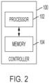
- the vehicle 10 may include a controller, such as controller 100, as is generally illustrated in FIG. 2 .
- the controller 100 may include any suitable controller, such as an electronic control unit or other suitable controller.
- the controller 100 may be configured to control, for example, the various functions of the steering system and/or various functions of the vehicle 10.
- the controller 100 may include a processor 102 and a memory 104.
- the processor 102 may include any suitable processor, such as those described herein. Additionally, or alternatively, the controller 100 may include any suitable number of processors, in addition to or other than the processor 102.
- the memory 104 may comprise a single disk or a plurality of disks (e.g., hard drives), and includes a storage management module that manages one or more partitions within the memory 104.
- memory 104 may include flash memory, semiconductor (solid state) memory or the like.
- the memory 104 may include Random Access Memory (RAM), a Read-Only Memory (ROM), or a combination thereof.
- RAM Random Access Memory
- ROM Read-Only Memory
- the memory 104 may include instructions that, when executed by the processor 102, cause the processor 102 to, at least, control various aspects of the vehicle 10.
- the controller 100 may be configured to provide phase-voltage based motor period measurement and controlled signal path fault detection.
- the controller 100 may interact with and/or control aspects of a circuit 200.
- the circuit 200 may include a first differential capacitively coupled interface 202 (e.g., which may be referred to herein as the first interface 202) and a second differential capacitively coupled interface 204 (e.g., which may be referred to herein as the second interface 204).
- the first interface 202 may be biased to mid-supply.
- the first interface 202 may include internal and/or external filtering blocks.
- the second interface 204 may be biased to mid-supply.
- the second interface 204 may include internal and/or external filtering blocks.
- Each of the first interface 202 and the second interface 204 may include various electrical components, such as capacitors, resistors, inductors, and the like.
- the first interface 202 and the second interface 204 may be in electrical communication with one or more power supply.
- the controller 100 may use one or more power supplies.
- the first interface 202 may be configured to provide a differential phase voltage input signal to a first integrated circuit 206. Additionally, or alternatively, the second interface 204 may be configured to provide a differential phase voltage input signal to a second integrated circuit 208.
- the differential phase voltage input signal interface may provide relatively high noise immunity.
- the circuit 200 may include an inverter system that routes phase voltage inputs of an electric motor 210 to the first integrated circuit 206 and the second integrated circuit 208, respectively.
- the inverter system may route a first phase voltage input (e.g., illustrated as VOL_PH1) and a second phase voltage input (e.g., illustrated as VOL_PH2_1) to the first integrated circuit 206.
- the inverter system may route the second phase voltage input (e.g., illustrated as VOL_PH2_2) and a third phase voltage input (e.g., illustrated as VOL_PH3) to the second integrated circuit 208.
- the inverter may route any combination of the first phase voltage input, the second phase voltage input, and the third phase voltage input to either of the first integrated circuit 206 and the second integrated circuit 208.
- each of the first integrated circuit 206 and the second integrated circuit 208 may use different pairs of phase voltage inputs to ensure redundancy in the measurement of period of the motor 210 during 6SO, which may provide enhanced tolerance to single point faults.
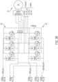
- the controller 100 and/or the circuit 200 may be configured to test and verify whether the complete IGBT control (e.g., include all six IGBT switches 220) and feedback signal path (as is generally illustrated in FIGS. 3A and 3B ) is connected and functioning according to various operating specifications.
- the controller 100 may, during power-up/initialization self-test operation (e.g., or other suitable operation), command a 3PSU and a 3PSL at a predetermined frequency.
- the frequency may include any suitable frequency including, but not limited to, a frequency up to 20 kilohertz. In some embodiments, the frequency may include a 10 kilohertz frequency or other suitable frequency.
- an integrated analog comparator and self-test block 212 of the first integrated circuit 206 may alternatingly monitor one of the phase voltage inputs (e.g., the first phase voltage input and the second phase voltage input) and compare the monitored phase voltage input to the mid-supply.
- a digital bock 214 may measure a period associated with the monitored phase voltage input.
- an integrated analog comparator and self-test block 216 of the second integrated circuit 208 may alternatingly monitor one of the phase voltage inputs (e.g., the second phase voltage input and the third phase voltage input) and compare the monitored phase voltage input to the mid-supply.
- a digital bock 218 may measure a period associated with the monitored phase voltage input. This may provide testability of both phase voltage signal paths for each of the first integrated circuit 206 and the second integrated circuit 208 (e.g., all three phase voltage input signal paths in the circuit 200) with execution of a single test.
- the controller 100 may read the measured period via a serial peripheral interface (SPI) or other suitable interface.
- the controller 100 may compare the measured period to the frequency associated with the commanded frequency.
- SPI serial peripheral interface
- a state machine associated with the circuit 200 may manage the test process.
- controller 100 and/or the circuit200 may support rejection of high voltage to low voltage domain ground disturbances.
- the controller 100 and/or the circuit 200 may increase fault coverage of the phases of the motor 210 (e.g., the first integrated circuit 206 and the second integrated circuit 208 cover all three phases).
- the first integrated circuit 206 may include an integrated secondary period counter and average bock 226 that provides a measurement of the average motor period over a user selectable number of readings.
- the controller 100 may use the average motor period as the measured period to compare to the commanded frequency to identify faults in the first integrated circuit 206.
- the second integrated circuit 208 may include an integrated secondary period counter and average block 228 that provides a measurement of the average motor period over a user selectable number of readings.
- the controller 100 may use the average motor period as the measured period to compare to the commanded frequency to identify faults in the second integrated circuit 208.
- the controller 100 may be configured to command generation of a phase voltage.
- the controller 100 may generate the commanded phase voltage during a power-up/initialization self-test operation of the circuit 200 or other suitable component of the vehicle 10. Additionally, or alternatively, the controller 100 may generate the commanded phase voltage during any suitable operation or at any suitable time.
- the commanded phase voltage may include a three phase short upper and a three phase short lower pattern or other suitable pattern.
- the controller 100 may apply the commanded phase voltage to the first phase voltage input of the motor 210 (e.g., which may be referred to as an electric motor), the second phase voltage input of the motor 210, and the third phase voltage input of the motor 210.
- the motor 210 may be associated with the vehicle 10.
- the motor 210 may be associated with any other suitable application in addition to or instead of the vehicle 10 and that the principles of the present disclosure apply accordingly.
- the first phase voltage input and the second phase voltage input may be connected to the first interface 202 and the second phase voltage input and the third phase voltage input may be connected to the second interface 204.
- the first interface 202 may be biased to a mid-supply and may be configured to provide the differential phase voltage input signal, based on the first phase voltage input and the second phase voltage input, to the first integrated circuit 206. Additionally, or alternatively, the first interface 202 may be configured to reject high frequency interconnect transients and to reject high voltage to low voltage domain ground disturbances.
- the second interface 204 may be biased to a mid-supply and may be configured to provide the differential phase voltage input signal, based on the second phase voltage input and third voltage input, to the second integrated circuit 208. Additionally, or alternatively, the second interface 204 may be configured to reject high frequency interconnect transients and to reject high voltage to low voltage domain ground disturbances.
- the controller 100 may measure, at the integrated analog comparator and self-test block 212 of the first integrated circuit 206, a first period of a phase voltage associated with the first phase voltage input and the second phase voltage input. The controller 100 may compare the first period of the phase voltage associated with the first phase voltage input and the second phase voltage input to the frequency associated with the commanded phase voltage. The controller 100 may determine whether the first period is within a range of the commanded frequency.
- the range may be any suitable range, such as plus or minus 1% or plus or minus one unit of measurement of the commanded frequency, or other suitable range.
- the controller 100 may identify a fault associated with the first integrated circuit 206 and/or a corresponding signal path. For example, the controller 100 may determine that a fault occurred in the first integrated circuit 206 and may identify the fault or the faulty component based on the comparison of the first period and the commanded frequency. The controller 100 may place the circuit 200 in a safe state of operation, such as any of the safe states of operation described herein, in response to a determination that a fault occurred in the first integrated circuit 206. Alternatively, if the controller 100 determines that the first period is within the range of the commanded frequency, the controller 100 determines that the first integrated circuit 206 is not faulty.
- the controller 100 may measure, at the integrated analog comparator and self-test block 216 of the second integrated circuit 208, a second period of a phase voltage associated with the second phase voltage input and the third phase voltage input. The controller 100 may compare the second period of the phase voltage associated with the second phase voltage input and the third phase voltage input to the frequency associated with the commanded phase voltage. The controller 100 may determine whether the second period is within the range of the commanded frequency.
- the controller 100 may identify a fault associated with the second integrated circuit 208 and/or a corresponding signal path. For example, the controller 100 may determine that a fault occurred in the second integrated circuit 208 and may identify the fault or the faulty component based on the comparing between the second period and the commanded frequency. The controller 100 may place the circuit 200 in a safe state of operation, such as any of the safe states of operation described herein, in response to a determination that a fault occurred in the second integrated circuit 208. Alternatively, if the controller 100 determines that the second period is within the range of the commanded frequency, the controller 100 determines that the second integrated circuit 208 and/or the corresponding signal path is not faulty.
- a safe state of operation such as any of the safe states of operation described herein
- the controller 100 and/or the circuit 200 may perform the methods described herein.
- the methods described herein as performed by the controller 100 and/or the circuit 200 are not meant to be limiting, and any type of software executed on a controller or processor can perform the methods described herein without departing from the scope of this disclosure.
- a controller such as a processor executing software within a computing device, can perform the methods described herein.
- FIG. 4 is a flow diagram generally illustrating a phase-voltage based motor period measurement method 400 according to the principles of the present disclosure.
- the method 400 generates a commanded phase voltage.
- the controller 100 may generate the commanded phase voltage.
- the method 400 applies the commanded phase voltage to a first phase voltage input of an electric motor, a second phase voltage input of the electric motor, and a third phase voltage input of the electric motor.
- the first phase voltage input and the second phase voltage input may be connected to a first differential capacitively coupled interface of a first integrated circuit and the second phase voltage input and the third phase voltage input may be connected to a second differential capacitively coupled interface of a second integrated circuit.
- the controller 100 may apply the commanded phase voltages to the first phase voltage input, the second phase voltage input, and the third phase voltage input.
- the method 400 measures, at an integrated analog comparator of the first integrated circuit, a first period of a phase voltage associated with the first phase voltage input and the second phase voltage input.
- the integrated analog comparator and self-test block 212 of the first integrated circuit 206 may measure the first period.
- the method 400 compares the first period of the phase voltage associated with the first phase voltage input and the second phase voltage input to a frequency associated with the commanded phase voltage.
- the controller 100 may compare the first period to the commanded frequency.
- the method 400 in response to a determination that the first period of the phase voltage associated with the first phase voltage input and the second phase voltage input is outside of a range of the frequency associated with the commanded phase voltage, identifies a fault associated with the first integrated circuit.
- the controller in response to a determination that the first period is outside of the range of the commanded frequency, identifies a fault in the first integrated circuit 206 and/or the corresponding signal path.
- the controller 100 may identify faults in the second integrated circuit 208 and/or the corresponding signal path, as described.
- a method for phase-voltage based motor period measurement includes generating a commanded phase voltage and applying the commanded phase voltage to a first phase voltage input of an electric motor, a second phase voltage input of the electric motor, and a third phase voltage input of the electric motor.
- the first phase voltage input and the second phase voltage input may be connected to a first differential capacitively coupled interface of a first integrated circuit and the second phase voltage input and the third phase voltage input may be connected to a second differential capacitively coupled interface of a second integrated circuit.
- the method also includes measuring, at an integrated analog comparator of the first integrated circuit, a first period of a phase voltage associated with the first phase voltage input and the second phase voltage input and comparing the first period of the phase voltage associated with the first phase voltage input and the second phase voltage input to a frequency associated with the commanded phase voltage.
- the method also includes, in response to a determination that the first period of the phase voltage associated with the first phase voltage input and the second phase voltage input is outside of a range of the frequency associated with the commanded phase voltage, identifying a fault associated with at least one of the first integrated circuit and a corresponding signal path.
- the method also includes measuring, at an integrated analog comparator of the second integrated circuit, a second period of a phase voltage associated with the second phase voltage input and the third phase voltage input, comparing the second period of the phase voltage associated with the second phase voltage input and the third phase voltage input to the frequency associated with the commanded phase voltage, and, in response to a determination that the second period of the phase voltage associated with the second phase voltage input and the third phase voltage input is outside of a range of the frequency associated with the commanded phase voltage, identifying a fault associated with at least one of the second integrated circuit and a corresponding signal path.
- the first differential capacitively coupled interface is biased to a mid-supply, and the first differential capacitively coupled interface is configured to provide a differential phase voltage input signal, based on the first phase voltage input and the second phase voltage input, to the first integrated circuit. In some embodiments, the first differential capacitively coupled interface is further configured to reject high frequency interconnect transients, and reject high voltage to low voltage domain ground disturbances. In some embodiments, the second differential capacitively coupled interface is biased to a mid-supply, and the second differential capacitively coupled interface is configured to provide a differential phase voltage input signal, based on the second phase voltage input and third voltage input, to the second integrated circuit.
- the second differential capacitively coupled interface is further configured to reject high frequency interconnect transients and reject high voltage to low voltage domain ground disturbances.
- the electric motor is associated with a vehicle.
- generating the commanded phase voltage includes generating the commanded phase voltage during a command of a self-test operation.
- the commanded phase voltage includes a three phase short upper and a three phase short lower pattern.
- the first integrated circuit includes a first application specific integrated circuit and wherein the second integrated circuit includes a second application specific integrated circuit.
- a system for phase-voltage based motor period measurement includes a processor and a memory.
- the memory includes instructions that, when executed by the processor, cause the processor to: generate a commanded phase voltage; apply the commanded phase voltage to a first phase voltage input of an electric motor, a second phase voltage input of the electric motor, and a third phase voltage input of the electric motor, the first phase voltage input and the second phase voltage input being connected to a first differential capacitively coupled interface of a first integrated circuit and the second phase voltage input and the third phase voltage input being connected to a second differential capacitively coupled interface of a second integrated circuit; measure, at an integrated analog comparator of the first integrated circuit, a first period of a phase voltage associated with the first phase voltage input and the second phase voltage input; compare the first period of the phase voltage associated with the first phase voltage input and the second phase voltage input to a frequency associated with the commanded phase voltage; and, in response to a determination that the first period of the phase voltage associated with the first phase voltage input and the second phase voltage input is outside of
- the instructions further cause the processor to measure, at an integrated analog comparator of the second integrated circuit, a second period of a phase voltage associated with the second phase voltage input and the third phase voltage input, compare the second period of the phase voltage associated with the second phase voltage input and the third phase voltage input to the frequency associated with the commanded phase voltage, and, in response to a determination that the second period of the phase voltage associated with the second phase voltage input and the third phase voltage input is outside of a range of the frequency associated with the commanded phase voltage, identify a fault associated with at least one of the second integrated circuit and a corresponding signal path.
- the first differential capacitively coupled interface is biased to a mid-supply, and wherein the first differential capacitively coupled interface is configured to provide a differential phase voltage input signal, based on the first phase voltage input and the second phase voltage input, to the first integrated circuit.
- the first differential capacitively coupled interface is further configured to reject high frequency interconnect transients and reject high voltage to low voltage domain ground disturbances.
- the second differential capacitively coupled interface is biased to a mid-supply, and the second differential capacitively coupled interface is configured to provide a differential phase voltage input signal, based on the second phase voltage input and third voltage input, to the second integrated circuit.
- the second differential capacitively coupled interface is further configured to reject high frequency interconnect transients and reject high voltage to low voltage domain ground disturbances.
- the electric motor is associated with a vehicle.
- the instructions further cause the processor to generate the commanded phase voltage during a command of a self-test operation.
- the commanded phase voltage includes a three phase short upper and a three phase short lower pattern.
- an apparatus for phase-voltage based motor period measurement includes a processor and a memory.
- the memory includes instructions that, when executed by the processor, cause the processor to: generate, during a command of a self-test operation, a commanded phase voltage; apply the commanded phase voltage to a first phase voltage input of an electric motor, a second phase voltage input of the electric motor, and a third phase voltage input of the electric motor, the first phase voltage input and the second phase voltage input being connected to a first differential capacitively coupled interface of a first integrated circuit and the second phase voltage input and the third phase voltage input being connected to a second differential capacitively coupled interface of a second integrated circuit; measure, at an integrated analog comparator of the first integrated circuit, a first period of a phase voltage associated with the first phase voltage input and the second phase voltage input; compare the first period of the phase voltage associated with the first phase voltage input and the second phase voltage input to a frequency associated with the commanded phase voltage; in response to a determination that the first period of the phase voltage associated with the
- example is used herein to mean serving as an example, instance, or illustration. Any aspect or design described herein as “example” is not necessarily to be construed as preferred or advantageous over other aspects or designs. Rather, use of the word “example” is intended to present concepts in a concrete fashion.
- the term “or” is intended to mean an inclusive “or” rather than an exclusive “or.” That is, unless specified otherwise, or clear from context, "X includes A or B” is intended to mean any of the natural inclusive permutations. That is, if X includes A; X includes B; or X includes both A and B, then "X includes A or B" is satisfied under any of the foregoing instances.
- Implementations of the systems, algorithms, methods, instructions, etc., described herein can be realized in hardware, software, or any combination thereof.
- the hardware can include, for example, computers, intellectual property (IP) cores, application-specific integrated circuits (ASICs), programmable logic arrays, optical processors, programmable logic controllers, microcode, microcontrollers, servers, microprocessors, digital signal processors, or any other suitable circuit.
- IP intellectual property
- ASICs application-specific integrated circuits
- programmable logic arrays optical processors
- programmable logic controllers microcode, microcontrollers
- servers microprocessors, digital signal processors, or any other suitable circuit.
- signal processors digital signal processors, or any other suitable circuit.
- module can include a packaged functional hardware unit designed for use with other components, a set of instructions executable by a controller (e.g., a processor executing software or firmware), processing circuitry configured to perform a particular function, and a self-contained hardware or software component that interfaces with a larger system.
- a module can include an application specific integrated circuit (ASIC), a Field Programmable Gate Array (FPGA), a circuit, digital logic circuit, an analog circuit, a combination of discrete circuits, gates, and other types of hardware or combination thereof.
- a module can include memory that stores instructions executable by a controller to implement a feature of the module.
- systems described herein can be implemented using a general-purpose computer or general-purpose processor with a computer program that, when executed, carries out any of the respective methods, algorithms, and/or instructions described herein.
- a special purpose computer/processor can be utilized which can contain other hardware for carrying out any of the methods, algorithms, or instructions described herein.
- implementations of the present disclosure can take the form of a computer program product accessible from, for example, a computer-usable or computer-readable medium.
- a computer-usable or computer-readable medium can be any device that can, for example, tangibly contain, store, communicate, or transport the program for use by or in connection with any processor.
- the medium can be, for example, an electronic, magnetic, optical, electromagnetic, or a semiconductor device. Other suitable mediums are also available.
Landscapes
- Physics & Mathematics (AREA)
- General Physics & Mathematics (AREA)
- Engineering & Computer Science (AREA)
- Power Engineering (AREA)
- Mechanical Engineering (AREA)
- Life Sciences & Earth Sciences (AREA)
- Sustainable Development (AREA)
- Sustainable Energy (AREA)
- Transportation (AREA)
- Control Of Ac Motors In General (AREA)
- Emergency Protection Circuit Devices (AREA)
Description
- This disclosure relates to vehicle circuits, and in particular, to systems and methods for phase-voltage based motor period measurement and controlled signal path fault detection.
- Vehicles, such as cars, trucks, sport utility vehicles, cross-overs, mini-vans, or other suitable vehicles, typically include various electric motors, such as permanent magnet motors or other suitable electric motors. Such electric motors may be used for various aspects of vehicle control or operation, such as vehicle prolusion or other suitable aspects of vehicle control or operation.
- In a typical electric motor, application of torque requires knowledge (e.g. by a controller of the vehicle) of motor position. However, when the circuitry for obtaining the motor position is faulted, the system associated with the electric motor is placed in a safe state of operation. Typically, this may include the controller or other suitable component determining a particular safe state of operation in which to place the system associated with the electric motor. To determine the particular safe state, the controller or other suitable component typically measures a speed of the electric motor. The controller or other suitable component may then use the measured speed of the motor to determine the particular safe state of operation. Such art is known from
DE1020182007 ,US5266891 , and from the IEEE paper "Modeling of Time Domain Analysis for Single and Double Open-Circuit Inverter Switch Faults in Three-Phase Induction Motor Drives", by Rasyadan et al, 2018 INTERNATIONAL CONFERENCE ON COMPUTATIONAL APPROACH IN SMART SYSTEMS DESIGN AND APPLICATIONS (ICASSDA), IEEE, 15 August 2018, pages 1-7, XP033410804. - This disclosure relates generally to electric motor control. The invention provides a method, a system, and an apparatus according to claims 1, 8, and 15, respectively.
- An aspect of the disclosed embodiments includes a method for phase-voltage based motor period measurement (e.g., where a period is inversely proportional to speed). The method includes generating a commanded phase voltage and applying the commanded phase voltage to a first phase voltage input of an electric motor, a second phase voltage input of the electric motor, and a third phase voltage input of the electric motor. The first phase voltage input and the second phase voltage input may be connected to a first differential capacitively coupled interface of a first integrated circuit and the second phase voltage input and the third phase voltage input may be connected to a second differential capacitively coupled interface of a second integrated circuit. The method also includes measuring, at an integrated analog comparator of the first integrated circuit, a first period of a phase voltage associated with the first phase voltage input and the second phase voltage input and comparing the first period of the phase voltage associated with the first phase voltage input and the second phase voltage input to a frequency associated with the commanded phase voltage. The method also includes, in response to a determination that the first period of the phase voltage associated with the first phase voltage input and the second phase voltage input is outside of a range of the frequency associated with the commanded phase voltage, identifying a fault associated with the first integrated circuit and/or a corresponding signal path.
- Another aspect of the disclosed embodiments includes a system for phase-voltage based motor period measurement. The system includes a processor and a memory. The memory includes instructions that, when executed by the processor, cause the processor to: command generation of a phase voltage with a defined period (e.g., frequency) during a command of self-test operation; apply the commanded phase voltage to a first phase voltage input of an electric motor, a second phase voltage input of the electric motor, and a third phase voltage input of the electric motor, the first phase voltage input and the second phase voltage input being connected to a first differential capacitively coupled interface of a first integrated circuit and the second phase voltage input and the third phase voltage input being connected to a second differential capacitively coupled interface of a second integrated circuit; measure, at an integrated analog comparator of the first integrated circuit, a first period of a phase voltage associated with the first phase voltage input and the second phase voltage input; compare the first period of the phase voltage associated with the first phase voltage input and the second phase voltage input to a frequency associated with the commanded phase voltage; and, in response to a determination that the first period of the phase voltage associated with the first phase voltage input and the second phase voltage input is outside of a range of the frequency associated with the commanded phase voltage, identify a fault associated with at least one of the first integrated circuit and a corresponding signal path.
- Another aspect of the disclosed embodiments includes an apparatus for phase-voltage based motor period measurement. The apparatus includes a processor and a memory. The memory includes instructions that, when executed by the processor, cause the processor to: command generation of a phase voltage with a defined period (e.g., frequency)during a power-up/initialization self-test operation; apply the commanded phase voltage to a first phase voltage input of an electric motor, a second phase voltage input of the electric motor, and a third phase voltage input of the electric motor, the first phase voltage input and the second phase voltage input being connected to a first differential capacitively coupled interface of a first integrated circuit and the second phase voltage input and the third phase voltage input being connected to a second differential capacitively coupled interface of a second integrated circuit; measure, at an integrated analog comparator of the first integrated circuit, a first period of a phase voltage associated with the first phase voltage input and the second phase voltage input; compare the first period of the phase voltage associated with the first phase voltage input and the second phase voltage input to a frequency associated with the commanded phase voltage; in response to a determination that the first period of the phase voltage associated with the first phase voltage input and the second phase voltage input is outside of a range of the frequency associated with the commanded phase voltage, identify a fault associated with at least one of the first integrated circuit and a corresponding signal path; measure, at an integrated analog comparator of the second integrated circuit, a second period of a phase voltage associated with the second phase voltage input and the third phase voltage input; compare the second period of the phase voltage associated with the second phase voltage input and the third phase voltage input to the frequency associated with the commanded phase voltage; and, in response to a determination that the second period of the phase voltage associated with the second phase voltage input and the third phase voltage input is outside of a range of the frequency associated with the commanded phase voltage, identify a fault associated with at least one of the second integrated circuit and a corresponding signal path.
- These and other aspects of the present disclosure are provided in the following detailed description of the embodiments, the appended claims, and the accompanying figures.
- The disclosure is best understood from the following detailed description when read in conjunction with the accompanying drawings. It is emphasized that, according to common practice, the various features of the drawings are not to-scale. On the contrary, the dimensions of the various features are arbitrarily expanded or reduced for clarity.
-
FIG. 1 generally illustrates a vehicle according to the principles of the present disclosure. -
FIG. 2 generally illustrates a controller according to the principles of the present disclosure. -
FIGS. 3 A and3B generally illustrate a phase-voltage based motor period measurement system according to the principles of the present disclosure. -
FIG. 4 is a flow diagram generally illustrating a phase-voltage based motor period measurement method according to the principles of the present disclosure. - The following discussion is directed to various embodiments of the invention. Although one or more of these embodiments may be preferred, the embodiments disclosed should not be interpreted, or otherwise used, as limiting the scope of the disclosure, including the claims. In addition, one skilled in the art will understand that the following description has broad application, and the discussion of any embodiment is meant only to be exemplary of that embodiment, and not intended to intimate that the scope of the disclosure, including the claims, is limited to that embodiment.
- As described, vehicles, such as cars, trucks, sport utility vehicles, cross-overs, mini-vans, or other suitable vehicles, typically include various electric motors, such as permanent magnet motors or other suitable electric motors. Such electric motors may be used for various aspects of vehicle control or operation, such as vehicle propulsion or other suitable aspects of vehicle control or operation.
- In a typical electric motor, application of torque requires knowledge (e.g. by a controller of the vehicle) of motor position. However, when the circuitry for obtaining the motor position is faulted, the system associated with the electric motor is placed in a safe state of operation. Typically, this may include the controller determining a particular safe state of operation in which to place the system associated with the electric motor. Placing the system associated with the electric motor in a safe state of operation while the vehicle is moving is typically done by the controller commanding either all six switches, while may include insulated gate bipolar transistor (IGBT) switches or other suitable switches, open (e.g., which may be referred to as six switch-open (6SO)) or by the controller commanding three upper/lower of the six IGBT switches closed (e.g., which may be referred to as a 3 phase-short upper/lower(3PSU/3PSL)).
- In order to determine which safe state of operation (e.g., 6SO or 3PS) in which to place the system associated with the electric motor, the controller, typically, measures a speed of the electric motor. The controller or other suitable component may then use the measured speed of the motor to determine the particular safe state of operation. For the vehicle to operate accordingly to a respective risk classification scheme, such as the automotive safety integrity level (ASIL) D or other suitable risk classification scheme), the vehicle may, for safe state operation control of the system associated with the electric motor, include a circuit that measures the speed of the electric motor and may include the ability to test that circuit with good coverage.
- Typically, solutions for providing a safe state of operation for the system associated with the electric motor may include using high voltage (HV) isolation amplifiers with HV resistor divider networks to communicate a single phase-voltage across the HV interface and to support motor speed measurement using a secondary microprocessor or controller, which may be relatively resource intensive and consume significant printed circuit board (PCB) real estate. In addition, such solutions typically do not address the lack of fault coverage diagnostics for an ASIL D compliant system. For example, such solutions: do not support testing for faults in the IGBT control and feedback path prior to enabling torque; use of a singular phase voltage feedback to monitor speed during 6SO (e.g., but not to test the continuity and integrity of the full control and feedback path for all six IGBTs during power-up/initialization self-test), monitor a single phase voltage only after entering torque/mission mode, and use single phase voltage feedback.
- Such solutions may result in a loss of visibility to the phase voltage input signal, in response to a fault in the singular feedback path. Additionally, or alternatively, such solutions may not be capable of measuring speed in the 6SO operating mode and therefore may fail to keep the system associated with the electric motor in an appropriate safe state of operation.
- Accordingly, systems and methods, such as those described herein, configured to provide phase-voltage based motor period measurement and controlled signal path fault detection, may be desirable. In some embodiments, the systems and the methods described herein may be configured to provide a phase-voltage based period measurement differential interface that includes HV isolation having relatively high immunity to coupled noise without the use of (relatively expensive) components. The systems and methods described herein may be configured to provide a functional safety test methodology that verifies the continuity and integrity of the complete IGBT control and feedback path using the controller and an application specific integrated circuit (ASIC) state machine.
- In some embodiments, the systems and methods described herein may be configured to use a differential capacitively coupled interface, biased to mid-supply and compared to each other. The systems and methods described herein may be configured to bias and appropriately filter (e.g., using corresponding filter circuitry) the systems associated with the electric motor to reject high frequency interconnect transients and support rejection of high voltage to low voltage domain ground disturbances.
- In some embodiments, the systems and methods described herein may be configured to provide relatively high tolerance to single point faults (SPF). The systems and methods described herein may be configured to use phase redundancy by routing three phases to two ASICs for period measurement. The systems and methods described herein may be configured to use a motor period detection block of a corresponding ASIC. The systems and methods described herein may be configured to command, using the controller, an alternating 3 phase short upper (3PSU) and 3 phase short lower (3PSL) pattern, at a predetermined period. The systems and methods described herein may be configured to compare the pattern to a measured period from the ASIC.
- In some embodiments, the systems and methods described herein may be configured to use the controller to control switching of the external IGBTs and to measure a period within the ASIC to verify that: the six IGBT drivers are working properly; the six IGBT gate drive power supplies are working properly; the six connections of the IGBT and the path is connected properly; the period measurements are relayed to the controller properly; the six IGBTs are switching in accordance with the controller commands; the passive components are connected properly between the IGBTs and the phase voltage feedback paths; and the phase voltage based motor period detection block is operating properly.
- In some embodiments, systems and methods described herein may be configured to provide a test of the system of the electric motor that is relatively easily executed and provides a relatively fast (e.g., 10 milliseconds or other suitable period) test response (e.g., of the entire path and for all IGBTs), which may enable relatively fast entry to mission mode operation. The systems and methods described herein may be configured to (e.g., using the differential interface topology, and redundant phase voltage inputs in combination with the controller and ASIC controlled test sequences) enable period measurement and fault detection, while supporting ASIL D functional safety requirements.
- In some embodiments, the systems and methods described herein may be configured to provide a solution that reduces PCB area and costs. The systems and methods described herein may be configured to accommodate ground domain differential voltages (alternating current (AC) and direct current (DC)) without the need for the isolation amplifier(s). The systems and methods described herein may be configured to eliminate the use of an HV resistor divider network and a secondary microprocessor for the period measurement. The systems and methods described herein may be configured to provide a controller and ASIC controlled test strategy where the full IGBT control and feedback path is tested, which may provide a comprehensive fault coverage prior to enabling torque.
- In some embodiments, the systems and methods described herein may be configured to generate a command phase voltage (e.g., by commanding the generation of the phase voltage). The systems and methods described herein may be configured to command the generation of the phase voltage during a command of a self-test operation or during any suitable operation or at any suitable time. The commanded phase voltage may include a three phase short upper and a three phase short lower pattern or other suitable pattern. The systems and methods described herein may be configured to apply the commanded phase voltage to a first phase voltage input of an electric motor, a second phase voltage input of the electric motor, and a third phase voltage input of the electric motor. The electric motor may be associated with a vehicle. However, it should be understood that the electric motor may be associated with any other suitable application in addition to or instead of the vehicle and that the principles of the present disclosure apply accordingly. The first phase voltage input and the second phase voltage input may be connected to a first differential capacitively coupled interface of a first integrated circuit and the second phase voltage input and the third phase voltage input may be connected to a second differential capacitively coupled interface of a second integrated circuit. The first integrated circuit may include a first ASIC and the second integrated circuit may include a second ASIC.
- In some embodiments, the first differential capacitively coupled interface may be biased to a mid-supply and may be configured to provide a differential phase voltage input signal, based on the first phase voltage input and the second phase voltage input, to the first integrated circuit. Additionally, or alternatively, the first differential capacitively coupled interface may be configured to reject high frequency interconnect transients and to reject high voltage to low voltage domain ground disturbances.
- In some embodiments, the second differential capacitively coupled interface may be biased to a mid-supply and may be configured to provide a differential phase voltage input signal, based on the second phase voltage input and third voltage input, to the second integrated circuit. Additionally, or alternatively, the second differential capacitively coupled interface may be configured to reject high frequency interconnect transients and to reject high voltage to low voltage domain ground disturbances.
- The systems and methods described herein may be configured to measure, at an integrated analog comparator of the first integrated circuit, a first period of a phase voltage associated with the first phase voltage input and the second phase voltage input. The systems and methods described herein may be configured to compare the first period of the phase voltage associated with the first phase voltage input and the second phase voltage input to a frequency associated with the commanded phase voltage. The systems and methods described herein may be configured to, in response to a determination that the first period of the phase voltage associated with the first phase voltage input and the second phase voltage input is outside of a range of the frequency associated with the commanded phase voltage, identify a fault associated with at least one of the first integrated circuit and a corresponding signal path.
- In some embodiments, the systems and methods described herein may be configured to measure, at an integrated analog comparator of the second integrated circuit, a second period of a phase voltage associated with the second phase voltage input and the third phase voltage input. The systems and methods described herein may be configured to compare the second period of the phase voltage associated with the second phase voltage input and the third phase voltage input to the frequency associated with the commanded phase voltage. The systems and methods described herein may be configured to, in response to a determination that the second period of the phase voltage associated with the second phase voltage input and the third phase voltage input is outside of a range of the frequency associated with the commanded phase voltage, identify a fault associated with at least one of the second integrated circuit and a corresponding signal path.
-
FIG. 1 generally illustrates avehicle 10 according to the principles of the present disclosure. Thevehicle 10 may include any suitable vehicle, such as a car, a truck, a sport utility vehicle, a mini-van, a cross-over, any other passenger vehicle, any suitable commercial vehicle, or any other suitable vehicle. While thevehicle 10 is illustrated as a passenger vehicle having wheels and for use on roads, the principles of the present disclosure may apply to other vehicles, such as planes, boats, trains, drones, or other suitable vehicles. Thevehicle 10 includes avehicle body 12 and ahood 14. A portion of thevehicle body 12 defines apassenger compartment 18. Another portion of thevehicle body 12 defines theengine compartment 20. Thehood 14 may be moveably attached to a portion of thevehicle body 12, such that thehood 14 provides access to theengine compartment 20 when thehood 14 is in a first or open position and thehood 14 covers theengine compartment 20 when thehood 14 is in a second or closed position. - The
passenger compartment 18 is disposed rearward of theengine compartment 20. Thevehicle 10 may include any suitable propulsion system including an internal combustion engine, one or more electric motors (e.g., an electric vehicle), one or more fuel cells, a hybrid (e.g., a hybrid vehicle) propulsion system comprising a combination of an internal combustion engine, one or more electric motors, and/or any other suitable propulsion system. In some embodiments, thevehicle 10 may include a petrol or gasoline fuel engine, such as a spark ignition engine. In some embodiments, thevehicle 10 may include a diesel fuel engine, such as a compression ignition engine. Theengine compartment 20 houses and/or encloses at least some components of the propulsion system of thevehicle 10. Additionally, or alternatively, propulsion controls, such as an accelerator actuator (e.g., an accelerator pedal), a brake actuator (e.g., a brake pedal), a steering wheel, and other such components are disposed in thepassenger compartment 18 of thevehicle 10. The propulsion controls may be actuated or controlled by a driver of thevehicle 10 and may be directly connected to corresponding components of the propulsion system, such as a throttle, a brake, a vehicle axle, a vehicle transmission, and the like, respectively. In some embodiments, the propulsion controls may communicate signals to a vehicle computer (e.g., drive by wire) which in turn may control the corresponding propulsion component of the propulsion system. - In some embodiments, the
vehicle 10 includes a transmission in communication with a crankshaft via a flywheel or clutch or fluid coupling. In some embodiments, the transmission includes a manual transmission. In some embodiments, the transmission includes an automatic transmission. Thevehicle 10 may include one or more pistons, in the case of an internal combustion engine or a hybrid vehicle, which cooperatively operate with the crankshaft to generate force which is translated through the transmission to one or more axles which turnswheels 22. When thevehicle 10 includes one or more electric motors, a vehicle battery and/or fuel cell provides energy to the electric motors to turn thewheels 22. In cases where thevehicle 10 includes a vehicle battery to provide energy to the one or more electric motors, when the battery is depleted, it may be connected to an electric grid (e.g., using a wall socket) to recharge the battery cells. Additionally, or alternatively, thevehicle 10 may employ regenerative braking which uses the one or more electric motors of thevehicle 10 as a generator to convert kinetic energy lost due to decelerating back into stored energy in the battery. - The
vehicle 10 may include automatic vehicle propulsion systems, such as a cruise control, an adaptive cruise control, automatic braking control, other automatic vehicle propulsion systems, or a combination thereof. Thevehicle 10 may be an autonomous or semi-autonomous vehicle, or other suitable type of vehicle. Thevehicle 10 may include additional or fewer features than those generally illustrated and/or disclosed herein. - In some embodiments, the
vehicle 10 may include a controller, such ascontroller 100, as is generally illustrated inFIG. 2 . Thecontroller 100 may include any suitable controller, such as an electronic control unit or other suitable controller. Thecontroller 100 may be configured to control, for example, the various functions of the steering system and/or various functions of thevehicle 10. Thecontroller 100 may include aprocessor 102 and amemory 104. Theprocessor 102 may include any suitable processor, such as those described herein. Additionally, or alternatively, thecontroller 100 may include any suitable number of processors, in addition to or other than theprocessor 102. Thememory 104 may comprise a single disk or a plurality of disks (e.g., hard drives), and includes a storage management module that manages one or more partitions within thememory 104. In some embodiments,memory 104 may include flash memory, semiconductor (solid state) memory or the like. Thememory 104 may include Random Access Memory (RAM), a Read-Only Memory (ROM), or a combination thereof. Thememory 104 may include instructions that, when executed by theprocessor 102, cause theprocessor 102 to, at least, control various aspects of thevehicle 10. - In some embodiments, the
controller 100 may be configured to provide phase-voltage based motor period measurement and controlled signal path fault detection. For examiner, thecontroller 100 may interact with and/or control aspects of acircuit 200. Thecircuit 200 may include a first differential capacitively coupled interface 202 (e.g., which may be referred to herein as the first interface 202) and a second differential capacitively coupled interface 204 (e.g., which may be referred to herein as the second interface 204). Thefirst interface 202 may be biased to mid-supply. Thefirst interface 202 may include internal and/or external filtering blocks. Thesecond interface 204 may be biased to mid-supply. Thesecond interface 204 may include internal and/or external filtering blocks. Each of thefirst interface 202 and thesecond interface 204 may include various electrical components, such as capacitors, resistors, inductors, and the like. Thefirst interface 202 and thesecond interface 204 may be in electrical communication with one or more power supply. Thecontroller 100 may use one or more power supplies. - In some embodiments, the
first interface 202 may be configured to provide a differential phase voltage input signal to a firstintegrated circuit 206. Additionally, or alternatively, thesecond interface 204 may be configured to provide a differential phase voltage input signal to a secondintegrated circuit 208. The differential phase voltage input signal interface may provide relatively high noise immunity. - In some embodiments, the
circuit 200 may include an inverter system that routes phase voltage inputs of anelectric motor 210 to the firstintegrated circuit 206 and the secondintegrated circuit 208, respectively. For example, the inverter system may route a first phase voltage input (e.g., illustrated as VOL_PH1) and a second phase voltage input (e.g., illustrated as VOL_PH2_1) to the firstintegrated circuit 206. Additionally, or alternatively, the inverter system may route the second phase voltage input (e.g., illustrated as VOL_PH2_2) and a third phase voltage input (e.g., illustrated as VOL_PH3) to the secondintegrated circuit 208. It should be understood that the inverter may route any combination of the first phase voltage input, the second phase voltage input, and the third phase voltage input to either of the firstintegrated circuit 206 and the secondintegrated circuit 208. - In some embodiments, each of the first
integrated circuit 206 and the secondintegrated circuit 208 may use different pairs of phase voltage inputs to ensure redundancy in the measurement of period of themotor 210 during 6SO, which may provide enhanced tolerance to single point faults. - In some embodiments, the
controller 100 and/or thecircuit 200 may be configured to test and verify whether the complete IGBT control (e.g., include all six IGBT switches 220) and feedback signal path (as is generally illustrated inFIGS. 3A and3B ) is connected and functioning according to various operating specifications. For example, thecontroller 100 may, during power-up/initialization self-test operation (e.g., or other suitable operation), command a 3PSU and a 3PSL at a predetermined frequency. The frequency may include any suitable frequency including, but not limited to, a frequency up to 20 kilohertz. In some embodiments, the frequency may include a 10 kilohertz frequency or other suitable frequency. - In some embodiments, an integrated analog comparator and self-
test block 212 of the firstintegrated circuit 206 may alternatingly monitor one of the phase voltage inputs (e.g., the first phase voltage input and the second phase voltage input) and compare the monitored phase voltage input to the mid-supply. Adigital bock 214 may measure a period associated with the monitored phase voltage input. Additionally, or alternatively, an integrated analog comparator and self-test block 216 of the secondintegrated circuit 208 may alternatingly monitor one of the phase voltage inputs (e.g., the second phase voltage input and the third phase voltage input) and compare the monitored phase voltage input to the mid-supply. Adigital bock 218 may measure a period associated with the monitored phase voltage input. This may provide testability of both phase voltage signal paths for each of the firstintegrated circuit 206 and the second integrated circuit 208 (e.g., all three phase voltage input signal paths in the circuit 200) with execution of a single test. - In some embodiments, the
controller 100 may read the measured period via a serial peripheral interface (SPI) or other suitable interface. Thecontroller 100 may compare the measured period to the frequency associated with the commanded frequency. - In some embodiments, a state machine associated with the
circuit 200 may manage the test process. In some embodiments,controller 100 and/or the circuit200 may support rejection of high voltage to low voltage domain ground disturbances. Thecontroller 100 and/or thecircuit 200 may increase fault coverage of the phases of the motor 210 (e.g., the firstintegrated circuit 206 and the secondintegrated circuit 208 cover all three phases). - In some embodiments, the first
integrated circuit 206 may include an integrated secondary period counter andaverage bock 226 that provides a measurement of the average motor period over a user selectable number of readings. Thecontroller 100 may use the average motor period as the measured period to compare to the commanded frequency to identify faults in the firstintegrated circuit 206. - In some embodiments, the second
integrated circuit 208 may include an integrated secondary period counter andaverage block 228 that provides a measurement of the average motor period over a user selectable number of readings. Thecontroller 100 may use the average motor period as the measured period to compare to the commanded frequency to identify faults in the secondintegrated circuit 208. - In some embodiments, the
controller 100 may be configured to command generation of a phase voltage. Thecontroller 100 may generate the commanded phase voltage during a power-up/initialization self-test operation of thecircuit 200 or other suitable component of thevehicle 10. Additionally, or alternatively, thecontroller 100 may generate the commanded phase voltage during any suitable operation or at any suitable time. The commanded phase voltage may include a three phase short upper and a three phase short lower pattern or other suitable pattern. - The
controller 100 may apply the commanded phase voltage to the first phase voltage input of the motor 210 (e.g., which may be referred to as an electric motor), the second phase voltage input of themotor 210, and the third phase voltage input of themotor 210. As described, themotor 210 may be associated with thevehicle 10. However, it should be understood that themotor 210 may be associated with any other suitable application in addition to or instead of thevehicle 10 and that the principles of the present disclosure apply accordingly. - As described, the first phase voltage input and the second phase voltage input may be connected to the
first interface 202 and the second phase voltage input and the third phase voltage input may be connected to thesecond interface 204. Thefirst interface 202 may be biased to a mid-supply and may be configured to provide the differential phase voltage input signal, based on the first phase voltage input and the second phase voltage input, to the firstintegrated circuit 206. Additionally, or alternatively, thefirst interface 202 may be configured to reject high frequency interconnect transients and to reject high voltage to low voltage domain ground disturbances. - In some embodiments, the
second interface 204 may be biased to a mid-supply and may be configured to provide the differential phase voltage input signal, based on the second phase voltage input and third voltage input, to the secondintegrated circuit 208. Additionally, or alternatively, thesecond interface 204 may be configured to reject high frequency interconnect transients and to reject high voltage to low voltage domain ground disturbances. - The
controller 100 may measure, at the integrated analog comparator and self-test block 212 of the firstintegrated circuit 206, a first period of a phase voltage associated with the first phase voltage input and the second phase voltage input. Thecontroller 100 may compare the first period of the phase voltage associated with the first phase voltage input and the second phase voltage input to the frequency associated with the commanded phase voltage. Thecontroller 100 may determine whether the first period is within a range of the commanded frequency. The range may be any suitable range, such as plus or minus 1% or plus or minus one unit of measurement of the commanded frequency, or other suitable range. - If the
controller 100 determines that the first period is outside of the range of the commanded frequency, thecontroller 100 may identify a fault associated with the firstintegrated circuit 206 and/or a corresponding signal path. For example, thecontroller 100 may determine that a fault occurred in the firstintegrated circuit 206 and may identify the fault or the faulty component based on the comparison of the first period and the commanded frequency. Thecontroller 100 may place thecircuit 200 in a safe state of operation, such as any of the safe states of operation described herein, in response to a determination that a fault occurred in the firstintegrated circuit 206. Alternatively, if thecontroller 100 determines that the first period is within the range of the commanded frequency, thecontroller 100 determines that the firstintegrated circuit 206 is not faulty. - In some embodiments, the
controller 100 may measure, at the integrated analog comparator and self-test block 216 of the secondintegrated circuit 208, a second period of a phase voltage associated with the second phase voltage input and the third phase voltage input. Thecontroller 100 may compare the second period of the phase voltage associated with the second phase voltage input and the third phase voltage input to the frequency associated with the commanded phase voltage. Thecontroller 100 may determine whether the second period is within the range of the commanded frequency. - If the
controller 100 determines that the second period is outside of the range of the commanded frequency, thecontroller 100 may identify a fault associated with the secondintegrated circuit 208 and/or a corresponding signal path. For example, thecontroller 100 may determine that a fault occurred in the secondintegrated circuit 208 and may identify the fault or the faulty component based on the comparing between the second period and the commanded frequency. Thecontroller 100 may place thecircuit 200 in a safe state of operation, such as any of the safe states of operation described herein, in response to a determination that a fault occurred in the secondintegrated circuit 208. Alternatively, if thecontroller 100 determines that the second period is within the range of the commanded frequency, thecontroller 100 determines that the secondintegrated circuit 208 and/or the corresponding signal path is not faulty. - In some embodiments, the
controller 100 and/or thecircuit 200 may perform the methods described herein. However, the methods described herein as performed by thecontroller 100 and/or thecircuit 200 are not meant to be limiting, and any type of software executed on a controller or processor can perform the methods described herein without departing from the scope of this disclosure. For example, a controller, such as a processor executing software within a computing device, can perform the methods described herein. -
FIG. 4 is a flow diagram generally illustrating a phase-voltage based motorperiod measurement method 400 according to the principles of the present disclosure. At 402, themethod 400 generates a commanded phase voltage. For example, thecontroller 100 may generate the commanded phase voltage. - At 404, the
method 400 applies the commanded phase voltage to a first phase voltage input of an electric motor, a second phase voltage input of the electric motor, and a third phase voltage input of the electric motor. The first phase voltage input and the second phase voltage input may be connected to a first differential capacitively coupled interface of a first integrated circuit and the second phase voltage input and the third phase voltage input may be connected to a second differential capacitively coupled interface of a second integrated circuit. For example, thecontroller 100 may apply the commanded phase voltages to the first phase voltage input, the second phase voltage input, and the third phase voltage input. - At 406, the
method 400 measures, at an integrated analog comparator of the first integrated circuit, a first period of a phase voltage associated with the first phase voltage input and the second phase voltage input. For example, the integrated analog comparator and self-test block 212 of the firstintegrated circuit 206 may measure the first period. - At 408, the
method 400 compares the first period of the phase voltage associated with the first phase voltage input and the second phase voltage input to a frequency associated with the commanded phase voltage. For example, thecontroller 100 may compare the first period to the commanded frequency. - At 410, the
method 400, in response to a determination that the first period of the phase voltage associated with the first phase voltage input and the second phase voltage input is outside of a range of the frequency associated with the commanded phase voltage, identifies a fault associated with the first integrated circuit. For example, the controller, in response to a determination that the first period is outside of the range of the commanded frequency, identifies a fault in the firstintegrated circuit 206 and/or the corresponding signal path. Thecontroller 100 may identify faults in the secondintegrated circuit 208 and/or the corresponding signal path, as described. - In some embodiments, a method for phase-voltage based motor period measurement includes generating a commanded phase voltage and applying the commanded phase voltage to a first phase voltage input of an electric motor, a second phase voltage input of the electric motor, and a third phase voltage input of the electric motor. The first phase voltage input and the second phase voltage input may be connected to a first differential capacitively coupled interface of a first integrated circuit and the second phase voltage input and the third phase voltage input may be connected to a second differential capacitively coupled interface of a second integrated circuit. The method also includes measuring, at an integrated analog comparator of the first integrated circuit, a first period of a phase voltage associated with the first phase voltage input and the second phase voltage input and comparing the first period of the phase voltage associated with the first phase voltage input and the second phase voltage input to a frequency associated with the commanded phase voltage. The method also includes, in response to a determination that the first period of the phase voltage associated with the first phase voltage input and the second phase voltage input is outside of a range of the frequency associated with the commanded phase voltage, identifying a fault associated with at least one of the first integrated circuit and a corresponding signal path.
- In some embodiments, the method also includes measuring, at an integrated analog comparator of the second integrated circuit, a second period of a phase voltage associated with the second phase voltage input and the third phase voltage input, comparing the second period of the phase voltage associated with the second phase voltage input and the third phase voltage input to the frequency associated with the commanded phase voltage, and, in response to a determination that the second period of the phase voltage associated with the second phase voltage input and the third phase voltage input is outside of a range of the frequency associated with the commanded phase voltage, identifying a fault associated with at least one of the second integrated circuit and a corresponding signal path. In some embodiments, the first differential capacitively coupled interface is biased to a mid-supply, and the first differential capacitively coupled interface is configured to provide a differential phase voltage input signal, based on the first phase voltage input and the second phase voltage input, to the first integrated circuit. In some embodiments, the first differential capacitively coupled interface is further configured to reject high frequency interconnect transients, and reject high voltage to low voltage domain ground disturbances. In some embodiments, the second differential capacitively coupled interface is biased to a mid-supply, and the second differential capacitively coupled interface is configured to provide a differential phase voltage input signal, based on the second phase voltage input and third voltage input, to the second integrated circuit. In some embodiments, the second differential capacitively coupled interface is further configured to reject high frequency interconnect transients and reject high voltage to low voltage domain ground disturbances. In some embodiments, the electric motor is associated with a vehicle. In some embodiments, generating the commanded phase voltage includes generating the commanded phase voltage during a command of a self-test operation. In some embodiments, the commanded phase voltage includes a three phase short upper and a three phase short lower pattern. In some embodiments, the first integrated circuit includes a first application specific integrated circuit and wherein the second integrated circuit includes a second application specific integrated circuit.
- In some embodiments, a system for phase-voltage based motor period measurement includes a processor and a memory. The memory includes instructions that, when executed by the processor, cause the processor to: generate a commanded phase voltage; apply the commanded phase voltage to a first phase voltage input of an electric motor, a second phase voltage input of the electric motor, and a third phase voltage input of the electric motor, the first phase voltage input and the second phase voltage input being connected to a first differential capacitively coupled interface of a first integrated circuit and the second phase voltage input and the third phase voltage input being connected to a second differential capacitively coupled interface of a second integrated circuit; measure, at an integrated analog comparator of the first integrated circuit, a first period of a phase voltage associated with the first phase voltage input and the second phase voltage input; compare the first period of the phase voltage associated with the first phase voltage input and the second phase voltage input to a frequency associated with the commanded phase voltage; and, in response to a determination that the first period of the phase voltage associated with the first phase voltage input and the second phase voltage input is outside of a range of the frequency associated with the commanded phase voltage, identify a fault associated with at least one of the first integrated circuit and a corresponding signal path.
- In some embodiments, the instructions further cause the processor to measure, at an integrated analog comparator of the second integrated circuit, a second period of a phase voltage associated with the second phase voltage input and the third phase voltage input, compare the second period of the phase voltage associated with the second phase voltage input and the third phase voltage input to the frequency associated with the commanded phase voltage, and, in response to a determination that the second period of the phase voltage associated with the second phase voltage input and the third phase voltage input is outside of a range of the frequency associated with the commanded phase voltage, identify a fault associated with at least one of the second integrated circuit and a corresponding signal path. In some embodiments, the first differential capacitively coupled interface is biased to a mid-supply, and wherein the first differential capacitively coupled interface is configured to provide a differential phase voltage input signal, based on the first phase voltage input and the second phase voltage input, to the first integrated circuit. In some embodiments, the first differential capacitively coupled interface is further configured to reject high frequency interconnect transients and reject high voltage to low voltage domain ground disturbances. In some embodiments, the second differential capacitively coupled interface is biased to a mid-supply, and the second differential capacitively coupled interface is configured to provide a differential phase voltage input signal, based on the second phase voltage input and third voltage input, to the second integrated circuit. In some embodiments, the second differential capacitively coupled interface is further configured to reject high frequency interconnect transients and reject high voltage to low voltage domain ground disturbances. In some embodiments, the electric motor is associated with a vehicle. In some embodiments, wherein the instructions further cause the processor to generate the commanded phase voltage during a command of a self-test operation. In some embodiments, the commanded phase voltage includes a three phase short upper and a three phase short lower pattern.
- In some embodiments, an apparatus for phase-voltage based motor period measurement. The apparatus includes a processor and a memory. The memory includes instructions that, when executed by the processor, cause the processor to: generate, during a command of a self-test operation, a commanded phase voltage; apply the commanded phase voltage to a first phase voltage input of an electric motor, a second phase voltage input of the electric motor, and a third phase voltage input of the electric motor, the first phase voltage input and the second phase voltage input being connected to a first differential capacitively coupled interface of a first integrated circuit and the second phase voltage input and the third phase voltage input being connected to a second differential capacitively coupled interface of a second integrated circuit; measure, at an integrated analog comparator of the first integrated circuit, a first period of a phase voltage associated with the first phase voltage input and the second phase voltage input; compare the first period of the phase voltage associated with the first phase voltage input and the second phase voltage input to a frequency associated with the commanded phase voltage; in response to a determination that the first period of the phase voltage associated with the first phase voltage input and the second phase voltage input is outside of a range of the frequency associated with the commanded phase voltage, identify a fault associated with at least one of the first integrated circuit and a corresponding signal path; measure, at an integrated analog comparator of the second integrated circuit, a second period of a phase voltage associated with the second phase voltage input and the third phase voltage input; compare the second period of the phase voltage associated with the second phase voltage input and the third phase voltage input to the frequency associated with the commanded phase voltage; and, in response to a determination that the second period of the phase voltage associated with the second phase voltage input and the third phase voltage input is outside of a range of the frequency associated with the commanded phase voltage, identify a fault associated with at least one of the second integrated circuit and a corresponding signal path.
- The above discussion is meant to be illustrative of the principles and various embodiments of the present disclosure. Numerous variations and modifications will become apparent to those skilled in the art once the above disclosure is fully appreciated. It is intended that the following claims be interpreted to embrace all such variations and modifications.
- The word "example" is used herein to mean serving as an example, instance, or illustration. Any aspect or design described herein as "example" is not necessarily to be construed as preferred or advantageous over other aspects or designs. Rather, use of the word "example" is intended to present concepts in a concrete fashion. As used in this application, the term "or" is intended to mean an inclusive "or" rather than an exclusive "or." That is, unless specified otherwise, or clear from context, "X includes A or B" is intended to mean any of the natural inclusive permutations. That is, if X includes A; X includes B; or X includes both A and B, then "X includes A or B" is satisfied under any of the foregoing instances. In addition, the articles "a" and "an" as used in this application and the appended claims should generally be construed to mean "one or more" unless specified otherwise or clear from context to be directed to a singular form. Moreover, use of the term "an implementation" or "one implementation" throughout is not intended to mean the same embodiment or implementation unless described as such.
- Implementations of the systems, algorithms, methods, instructions, etc., described herein can be realized in hardware, software, or any combination thereof. The hardware can include, for example, computers, intellectual property (IP) cores, application-specific integrated circuits (ASICs), programmable logic arrays, optical processors, programmable logic controllers, microcode, microcontrollers, servers, microprocessors, digital signal processors, or any other suitable circuit. In the claims, the term "processor" should be understood as encompassing any of the foregoing hardware, either singly or in combination. The terms "signal" and "data" are used interchangeably.
- As used herein, the term module can include a packaged functional hardware unit designed for use with other components, a set of instructions executable by a controller (e.g., a processor executing software or firmware), processing circuitry configured to perform a particular function, and a self-contained hardware or software component that interfaces with a larger system. For example, a module can include an application specific integrated circuit (ASIC), a Field Programmable Gate Array (FPGA), a circuit, digital logic circuit, an analog circuit, a combination of discrete circuits, gates, and other types of hardware or combination thereof. In other embodiments, a module can include memory that stores instructions executable by a controller to implement a feature of the module.
- Further, in one aspect, for example, systems described herein can be implemented using a general-purpose computer or general-purpose processor with a computer program that, when executed, carries out any of the respective methods, algorithms, and/or instructions described herein. In addition, or alternatively, for example, a special purpose computer/processor can be utilized which can contain other hardware for carrying out any of the methods, algorithms, or instructions described herein.
- Further, all or a portion of implementations of the present disclosure can take the form of a computer program product accessible from, for example, a computer-usable or computer-readable medium. A computer-usable or computer-readable medium can be any device that can, for example, tangibly contain, store, communicate, or transport the program for use by or in connection with any processor. The medium can be, for example, an electronic, magnetic, optical, electromagnetic, or a semiconductor device. Other suitable mediums are also available.
- The above-described embodiments, implementations, and aspects have been described to allow easy understanding of the present disclosure and do not limit the present disclosure. On the contrary, the disclosure is intended to cover various modifications and equivalent arrangements included within the scope as defined by the appended claims.
Claims (15)
- A method (400) for phase-voltage based motor period measurement, the method comprising generating (402) a commanded phase voltage;applying (404) the commanded phase voltage to a first phase voltage input of an electric motor, a second phase voltage input of the electric motor, and a third phase voltage input of the electric motor, the first phase voltage input and the second phase voltage input being connected to a first differential capacitively coupled interface of a first integrated circuit and the second phase voltage input and the third phase voltage input being connected to a second differential capacitively coupled interface of a second integrated circuit;measuring (406), at an integrated analog comparator of the first integrated circuit, a first period of a phase voltage associated with the first phase voltage input and the second phase voltage input; comparing (408) the first period of the phase voltage associated with the first phase voltage input and the second phase voltage input to a frequency associated with the commanded phase voltage; andin response (410) to a determination that the first period of the phase voltage associated with the first phase voltage input and the second phase voltage input is outside of a range of the frequency associated with the commanded phase voltage, identifying a fault associated with at least one of the first integrated circuit and a corresponding signal path
- The method of claim 1, further comprising:measuring, at an integrated analog comparator of the second integrated circuit, a second period of a phase voltage associated with the second phase voltage input and the third phase voltage input;comparing the second period of the phase voltage associated with the second phase voltage input and the third phase voltage input to the frequency associated with the commanded phase voltage; andin response to a determination that the second period of the phase voltage associated with the second phase voltage input and the third phase voltage input is outside of a range of the frequency associated with the commanded phase voltage, identifying a fault associated with at least one of the second integrated circuit and a corresponding signal path.
- The method of claim 1 or 2, wherein the first differential capacitively coupled interface is biased to a mid-supply, and wherein the first differential capacitively coupled interface is configured to provide a differential phase voltage input signal, based on the first phase voltage input and the second phase voltage input, to the first integrated circuit, said first differential capacitively coupled interface being preferably further configured to reject high frequency interconnect transients; and reject high voltage to low voltage domain ground disturbances.
- The method of claim 1 or 2, wherein the second differential capacitively coupled interface is biased to a mid-supply, and wherein the second differential capacitively coupled interface is configured to provide a differential phase voltage input signal, based on the second phase voltage input and third phase voltage input, to the second integrated circuit, said second differential capacitively coupled interface being preferably further configured to reject high frequency interconnect transients; and reject high voltage to low voltage domain ground disturbances.
- The method of any one of claims 1 to 4, wherein generating the commanded phase voltage includes generating the commanded phase voltage during a command of a self-test operation.
- The method of any one of claims 1 to 5, wherein the commanded phase voltage includes a three phase short upper and a three phase short lower pattern.
- The method of any one of claims 1 to 6, wherein the first integrated circuit includes a first application specific integrated circuit and wherein the second integrated circuit includes a second application specific integrated circuit.
- A system for phase-voltage based motor period measurement, the system comprising:a processor (102); anda memory (104) including instructions that, when executed by the processor, cause the processor to generate a commanded phase voltage;apply the commanded phase voltage to a first phase voltage input of an electric motor, a second phase voltage input of the electric motor, and a third phase voltage input of the electric motor, the first phase voltage input and the second phase voltage input being connected to a first differential capacitively coupled interface (202) of a first integrated circuit (206) and the second phase voltage input and the third phase voltage input being connected to a second differential capacitively coupled interface (204) of a second integrated circuit (208);measure, at an integrated analog comparator (212) of the first integrated circuit, a first period of a phase voltage associated with the first phase voltage input and the second phase voltage input;compare the first period of the phase voltage associated with the first phase voltage input and the second phase voltage input to a frequency associated with the commanded phase voltage; andin response to a determination that the first period of the phase voltage associated with the first phase voltage input and the second phase voltage input is outside of a range of the frequency associated with the commanded phase voltage, identify a fault associated with at least one of the first integrated circuit and a corresponding signal path.
- The system of claim 8, wherein the instructions further cause the processor to:measure, at an integrated analog comparator of the second integrated circuit, a second period of a phase voltage associated with the second phase voltage input and the third phase voltage input;compare the second period of the phase voltage associated with the second phase voltage input and the third phase voltage input to the frequency associated with the commanded phase voltage; andin response to a determination that the second period of the phase voltage associated with the second phase voltage input and the third phase voltage input is outside of a range of the frequency associated with the commanded phase voltage, identify a fault associated with at least one of the second integrated circuit and a corresponding signal path.
- The system of any one of claims 8 to 9, wherein the first differential capacitively coupled interface is biased to a mid-supply, and wherein the first differential capacitively coupled interface is configured to provide a differential phase voltage input signal, based on the first phase voltage input and the second phase voltage input, to the first integrated circuit, said first differential capacitively coupled interface being preferably further configured to reject high frequency interconnect transients; and reject high voltage to low voltage domain ground disturbances.
- The system of any one of claims 8 to 9, wherein the second differential capacitively coupled interface is biased to a mid-supply, and wherein the second differential capacitively coupled interface is configured to provide a differential phase voltage input signal, based on the second phase voltage input and third phase voltage input, to the second integrated circuit, said second differential capacitively coupled interface being preferably further configured to reject high frequency interconnect transients; and reject high voltage to low voltage domain ground disturbances.
- The system of any one of claims 8 to 11, wherein the instructions further cause the processor to generate the commanded phase voltage during a command of a self-test operation.
- The system of any one of claims 8 to 12, wherein the commanded phase voltage includes a three phase short upper and a three phase short lower pattern.
- The method of any one of claims 1 to 7 or the system of any one of claims 8 to 13, wherein the electric motor is associated with a vehicle.
- An apparatus for phase-voltage based motor period measurement, the apparatus comprising:a processor (102); anda memory (104)including instructions that, when executed by the processor, cause the processor togenerate, during a command of a self-test operation, a commanded phase voltage;apply the commanded phase voltage to a first phase voltage input of an electric motor, a second phase voltage input of the electric motor, and a third phase voltage input of the electric motor, the first phase voltage input and the second phase voltage input being connected to a first differential capacitively coupled interface (202) of a first integrated circuit (206) and the second phase voltage input and the third phase voltage input being connected to a second differential capacitively coupled interface (204) of a second integrated circuit (208);measure, at an integrated analog comparator (212) of the first integrated circuit, a first period of a phase voltage associated with the first phase voltage input and the second phase voltage input;compare the first period of the phase voltage associated with the first phase voltage input and the second phase voltage input to a frequency associated with the commanded phase voltage;in response to a determination that the first period of the phase voltage associated with the first phase voltage input and the second phase voltage input is outside of a range of the frequency associated with the commanded phase voltage, identify a fault associated with at least one of the first integrated circuit and a corresponding signal path;measure, at an integrated analog comparator (216) of the second integrated circuit, a second period of a phase voltage associated with the second phase voltage input and the third phase voltage input;compare the second period of the phase voltage associated with the second phase voltage input and the third phase voltage input to the frequency associated with the commanded phase voltage; andin response to a determination that the second period of the phase voltage associated with the second phase voltage input and the third phase voltage input is outside of a range of the frequency associated with the commanded phase voltage, identify a fault associated with at least one of the second integrated circuit and a corresponding signal path.
Applications Claiming Priority (1)
| Application Number | Priority Date | Filing Date | Title |
|---|---|---|---|
| US17/321,020 US11557992B2 (en) | 2021-05-14 | 2021-05-14 | Systems and methods for phase-voltage based motor period measurement and controlled signal path fault detection |
Publications (3)
| Publication Number | Publication Date |
|---|---|
| EP4089426A2 EP4089426A2 (en) | 2022-11-16 |
| EP4089426A3 EP4089426A3 (en) | 2022-11-23 |
| EP4089426B1 true EP4089426B1 (en) | 2024-04-03 |
Family
ID=81580396
Family Applications (1)
| Application Number | Title | Priority Date | Filing Date |
|---|---|---|---|
| EP22171468.6A Active EP4089426B1 (en) | 2021-05-14 | 2022-05-03 | Systems and methods for phase-voltage based motor period measurement and controlled signal path fault detection |
Country Status (4)
| Country | Link |
|---|---|
| US (1) | US11557992B2 (en) |
| EP (1) | EP4089426B1 (en) |
| KR (1) | KR102695479B1 (en) |
| CN (1) | CN115343612B (en) |
Family Cites Families (11)
| Publication number | Priority date | Publication date | Assignee | Title |
|---|---|---|---|---|
| US5266891A (en) | 1990-12-20 | 1993-11-30 | General Electric Company | Auto self test of AC motor system |
| JP4632170B2 (en) * | 2004-12-13 | 2011-02-16 | 株式会社安川電機 | Inverter control device for induction motor |
| US8035322B2 (en) * | 2008-05-16 | 2011-10-11 | Turner Larry A | Methods and apparatuses for estimating transient slip |
| US9525372B2 (en) | 2013-02-20 | 2016-12-20 | Microchip Technology Incorporated | Method and system for determining the position of a synchronous motor's rotor |
| KR101765977B1 (en) * | 2013-04-16 | 2017-08-07 | 주식회사 만도 | Motor driving apparatus |
| US9329219B2 (en) * | 2013-07-16 | 2016-05-03 | GM Global Technology Operations LLC | System and method of using flexible ECU inputs to specifically determine the type of electrical fault on an input |
| KR101907457B1 (en) * | 2016-07-13 | 2018-10-12 | 현대오트론 주식회사 | Method and apparatus for measuring average current of 3 phase motor based on current measurement of pwm on-duty period |
| KR101997834B1 (en) * | 2017-12-14 | 2019-07-08 | 현대오트론 주식회사 | An Apparatus and A Method For Motor Failure Diagnosis |
| DE102018200717A1 (en) | 2018-01-17 | 2019-07-18 | Robert Bosch Gmbh | Method for testing bridges of an output stage while the machine is rotating |
| CN110165950B (en) * | 2019-05-25 | 2021-03-09 | 福州伊柯达信息技术有限公司 | Two-phase hybrid stepping motor step-out judging method |
| JP7577525B2 (en) * | 2020-12-14 | 2024-11-05 | ローム株式会社 | Motor Driver Device |
-
2021
- 2021-05-14 US US17/321,020 patent/US11557992B2/en active Active
-
2022
- 2022-05-03 EP EP22171468.6A patent/EP4089426B1/en active Active
- 2022-05-10 CN CN202210503354.2A patent/CN115343612B/en active Active
- 2022-05-13 KR KR1020220058912A patent/KR102695479B1/en active Active
Also Published As
| Publication number | Publication date |
|---|---|
| EP4089426A2 (en) | 2022-11-16 |
| EP4089426A3 (en) | 2022-11-23 |
| KR102695479B1 (en) | 2024-08-14 |
| CN115343612A (en) | 2022-11-15 |
| KR20220155228A (en) | 2022-11-22 |
| US11557992B2 (en) | 2023-01-17 |
| CN115343612B (en) | 2025-09-12 |
| US20220368253A1 (en) | 2022-11-17 |
Similar Documents
| Publication | Publication Date | Title |
|---|---|---|
| CN112689952B (en) | Motor angle detection and diagnosis device, motor controller, electric vehicle and method | |
| US8310272B2 (en) | Method and system for testing electric automotive drive systems | |
| CN109669092B (en) | Electrified Vehicle Powertrain Monitoring Systems | |
| US10598732B2 (en) | Early detection of motor stator winding faults | |
| US9630512B2 (en) | System and method for controlling energy under interlock of eco-friendly vehicle | |
| US11353490B2 (en) | Systems and methods for monitoring voltage of vehicle onboard battery charger | |
| CN112519581B (en) | System and method for noise elimination in protective earth resistance inspection of vehicle on-board battery chargers | |
| US11186193B2 (en) | System and method for controlling charging power of eco-friendly vehicle | |
| EP4089426B1 (en) | Systems and methods for phase-voltage based motor period measurement and controlled signal path fault detection | |
| CN112440801A (en) | System and method for smooth start of vehicle on-board battery charger | |
| CN117060555A (en) | State determination method of power supply system and relays in power supply system | |
| Liu et al. | Design methodology of hybrid electric vehicle energy sources: Application to fuel cell vehicles | |
| Zhang et al. | Fault diagnosis and fault tolerant control for electrified vehicle torque security | |
| EP4141452B1 (en) | Systems and methods for fail-safe resolver excitation | |
| Tashakori | Review on VSI Switch Fault Tolerant Control Systems for Electric Vehicle Drivetrains. | |
| CN115347846B (en) | Dual power supply dual control architecture | |
| Park et al. | Dynamic modeling and simulation for battery electric vehicles under inverter fault conditions | |
| Hentunen et al. | Full-Scale Hardware-in-the-Loop Verification Environment for Heavy Duty Hybrid Electric Vehicles | |
| Tashakori Abkenar | Review on VSI switch fault tolerant control systems for electric vehicle drivetrains | |
| CN115402133A (en) | Isolated charging for multiple AC charging inputs | |
| Thomas | Modular Energy Storage System for Hydrogen Fuel Cell Vehicles | |
| Sültrop | Flexible Vehicle Control Unit for Drivetrains exclusively from Power Electronics Prototypes |
Legal Events
| Date | Code | Title | Description |
|---|---|---|---|
| PUAI | Public reference made under article 153(3) epc to a published international application that has entered the european phase |
Free format text: ORIGINAL CODE: 0009012 |
|
| STAA | Information on the status of an ep patent application or granted ep patent |
Free format text: STATUS: THE APPLICATION HAS BEEN PUBLISHED |
|
| PUAL | Search report despatched |
Free format text: ORIGINAL CODE: 0009013 |
|
| AK | Designated contracting states |
Kind code of ref document: A2 Designated state(s): AL AT BE BG CH CY CZ DE DK EE ES FI FR GB GR HR HU IE IS IT LI LT LU LV MC MK MT NL NO PL PT RO RS SE SI SK SM TR |
|
| AK | Designated contracting states |
Kind code of ref document: A3 Designated state(s): AL AT BE BG CH CY CZ DE DK EE ES FI FR GB GR HR HU IE IS IT LI LT LU LV MC MK MT NL NO PL PT RO RS SE SI SK SM TR |
|
| RIC1 | Information provided on ipc code assigned before grant |
Ipc: G01R 23/00 20060101ALI20221019BHEP Ipc: G01R 23/02 20060101ALI20221019BHEP Ipc: G01R 31/42 20060101ALI20221019BHEP Ipc: G01R 31/34 20200101AFI20221019BHEP |
|
| STAA | Information on the status of an ep patent application or granted ep patent |
Free format text: STATUS: REQUEST FOR EXAMINATION WAS MADE |
|
| 17P | Request for examination filed |
Effective date: 20230327 |
|
| RBV | Designated contracting states (corrected) |
Designated state(s): AL AT BE BG CH CY CZ DE DK EE ES FI FR GB GR HR HU IE IS IT LI LT LU LV MC MK MT NL NO PL PT RO RS SE SI SK SM TR |
|
| P01 | Opt-out of the competence of the unified patent court (upc) registered |
Effective date: 20230327 |
|
| GRAP | Despatch of communication of intention to grant a patent |
Free format text: ORIGINAL CODE: EPIDOSNIGR1 |
|
| STAA | Information on the status of an ep patent application or granted ep patent |
Free format text: STATUS: GRANT OF PATENT IS INTENDED |
|
| RIC1 | Information provided on ipc code assigned before grant |
Ipc: G01R 23/00 20060101ALI20230904BHEP Ipc: G01R 23/02 20060101ALI20230904BHEP Ipc: G01R 31/42 20060101ALI20230904BHEP Ipc: G01R 31/34 20200101AFI20230904BHEP |
|
| INTG | Intention to grant announced |
Effective date: 20230921 |
|
| GRAJ | Information related to disapproval of communication of intention to grant by the applicant or resumption of examination proceedings by the epo deleted |
Free format text: ORIGINAL CODE: EPIDOSDIGR1 |
|
| STAA | Information on the status of an ep patent application or granted ep patent |
Free format text: STATUS: REQUEST FOR EXAMINATION WAS MADE |
|
| GRAP | Despatch of communication of intention to grant a patent |
Free format text: ORIGINAL CODE: EPIDOSNIGR1 |
|
| STAA | Information on the status of an ep patent application or granted ep patent |
Free format text: STATUS: GRANT OF PATENT IS INTENDED |
|
| GRAS | Grant fee paid |
Free format text: ORIGINAL CODE: EPIDOSNIGR3 |
|
| INTC | Intention to grant announced (deleted) | ||
| GRAA | (expected) grant |
Free format text: ORIGINAL CODE: 0009210 |
|
| STAA | Information on the status of an ep patent application or granted ep patent |
Free format text: STATUS: THE PATENT HAS BEEN GRANTED |
|
| INTG | Intention to grant announced |
Effective date: 20240209 |
|
| AK | Designated contracting states |
Kind code of ref document: B1 Designated state(s): AL AT BE BG CH CY CZ DE DK EE ES FI FR GB GR HR HU IE IS IT LI LT LU LV MC MK MT NL NO PL PT RO RS SE SI SK SM TR |
|
| REG | Reference to a national code |
Ref country code: CH Ref legal event code: EP |
|
| REG | Reference to a national code |
Ref country code: IE Ref legal event code: FG4D |
|
| REG | Reference to a national code |
Ref country code: DE Ref legal event code: R096 Ref document number: 602022002636 Country of ref document: DE |
|
| REG | Reference to a national code |
Ref country code: LT Ref legal event code: MG9D |
|
| REG | Reference to a national code |
Ref country code: NL Ref legal event code: MP Effective date: 20240403 |
|
| REG | Reference to a national code |
Ref country code: AT Ref legal event code: MK05 Ref document number: 1672925 Country of ref document: AT Kind code of ref document: T Effective date: 20240403 |
|
| PG25 | Lapsed in a contracting state [announced via postgrant information from national office to epo] |
Ref country code: NL Free format text: LAPSE BECAUSE OF FAILURE TO SUBMIT A TRANSLATION OF THE DESCRIPTION OR TO PAY THE FEE WITHIN THE PRESCRIBED TIME-LIMIT Effective date: 20240403 |
|
| PG25 | Lapsed in a contracting state [announced via postgrant information from national office to epo] |
Ref country code: NL Free format text: LAPSE BECAUSE OF FAILURE TO SUBMIT A TRANSLATION OF THE DESCRIPTION OR TO PAY THE FEE WITHIN THE PRESCRIBED TIME-LIMIT Effective date: 20240403 |
|
| PG25 | Lapsed in a contracting state [announced via postgrant information from national office to epo] |
Ref country code: IS Free format text: LAPSE BECAUSE OF FAILURE TO SUBMIT A TRANSLATION OF THE DESCRIPTION OR TO PAY THE FEE WITHIN THE PRESCRIBED TIME-LIMIT Effective date: 20240803 |
|
| PG25 | Lapsed in a contracting state [announced via postgrant information from national office to epo] |
Ref country code: BG Free format text: LAPSE BECAUSE OF FAILURE TO SUBMIT A TRANSLATION OF THE DESCRIPTION OR TO PAY THE FEE WITHIN THE PRESCRIBED TIME-LIMIT Effective date: 20240403 |
|
| PG25 | Lapsed in a contracting state [announced via postgrant information from national office to epo] |
Ref country code: HR Free format text: LAPSE BECAUSE OF FAILURE TO SUBMIT A TRANSLATION OF THE DESCRIPTION OR TO PAY THE FEE WITHIN THE PRESCRIBED TIME-LIMIT Effective date: 20240403 Ref country code: FI Free format text: LAPSE BECAUSE OF FAILURE TO SUBMIT A TRANSLATION OF THE DESCRIPTION OR TO PAY THE FEE WITHIN THE PRESCRIBED TIME-LIMIT Effective date: 20240403 |
|
| PG25 | Lapsed in a contracting state [announced via postgrant information from national office to epo] |
Ref country code: GR Free format text: LAPSE BECAUSE OF FAILURE TO SUBMIT A TRANSLATION OF THE DESCRIPTION OR TO PAY THE FEE WITHIN THE PRESCRIBED TIME-LIMIT Effective date: 20240704 |
|
| PG25 | Lapsed in a contracting state [announced via postgrant information from national office to epo] |
Ref country code: PT Free format text: LAPSE BECAUSE OF FAILURE TO SUBMIT A TRANSLATION OF THE DESCRIPTION OR TO PAY THE FEE WITHIN THE PRESCRIBED TIME-LIMIT Effective date: 20240805 |
|
| PG25 | Lapsed in a contracting state [announced via postgrant information from national office to epo] |
Ref country code: ES Free format text: LAPSE BECAUSE OF FAILURE TO SUBMIT A TRANSLATION OF THE DESCRIPTION OR TO PAY THE FEE WITHIN THE PRESCRIBED TIME-LIMIT Effective date: 20240403 |
|
| PG25 | Lapsed in a contracting state [announced via postgrant information from national office to epo] |
Ref country code: CZ Free format text: LAPSE BECAUSE OF FAILURE TO SUBMIT A TRANSLATION OF THE DESCRIPTION OR TO PAY THE FEE WITHIN THE PRESCRIBED TIME-LIMIT Effective date: 20240403 |
|
| PG25 | Lapsed in a contracting state [announced via postgrant information from national office to epo] |
Ref country code: AT Free format text: LAPSE BECAUSE OF FAILURE TO SUBMIT A TRANSLATION OF THE DESCRIPTION OR TO PAY THE FEE WITHIN THE PRESCRIBED TIME-LIMIT Effective date: 20240403 |
|
| PG25 | Lapsed in a contracting state [announced via postgrant information from national office to epo] |
Ref country code: PL Free format text: LAPSE BECAUSE OF FAILURE TO SUBMIT A TRANSLATION OF THE DESCRIPTION OR TO PAY THE FEE WITHIN THE PRESCRIBED TIME-LIMIT Effective date: 20240403 |
|
| PG25 | Lapsed in a contracting state [announced via postgrant information from national office to epo] |
Ref country code: LV Free format text: LAPSE BECAUSE OF FAILURE TO SUBMIT A TRANSLATION OF THE DESCRIPTION OR TO PAY THE FEE WITHIN THE PRESCRIBED TIME-LIMIT Effective date: 20240403 |
|
| PG25 | Lapsed in a contracting state [announced via postgrant information from national office to epo] |
Ref country code: PT Free format text: LAPSE BECAUSE OF FAILURE TO SUBMIT A TRANSLATION OF THE DESCRIPTION OR TO PAY THE FEE WITHIN THE PRESCRIBED TIME-LIMIT Effective date: 20240805 Ref country code: PL Free format text: LAPSE BECAUSE OF FAILURE TO SUBMIT A TRANSLATION OF THE DESCRIPTION OR TO PAY THE FEE WITHIN THE PRESCRIBED TIME-LIMIT Effective date: 20240403 Ref country code: NO Free format text: LAPSE BECAUSE OF FAILURE TO SUBMIT A TRANSLATION OF THE DESCRIPTION OR TO PAY THE FEE WITHIN THE PRESCRIBED TIME-LIMIT Effective date: 20240703 Ref country code: LV Free format text: LAPSE BECAUSE OF FAILURE TO SUBMIT A TRANSLATION OF THE DESCRIPTION OR TO PAY THE FEE WITHIN THE PRESCRIBED TIME-LIMIT Effective date: 20240403 Ref country code: IS Free format text: LAPSE BECAUSE OF FAILURE TO SUBMIT A TRANSLATION OF THE DESCRIPTION OR TO PAY THE FEE WITHIN THE PRESCRIBED TIME-LIMIT Effective date: 20240803 Ref country code: HR Free format text: LAPSE BECAUSE OF FAILURE TO SUBMIT A TRANSLATION OF THE DESCRIPTION OR TO PAY THE FEE WITHIN THE PRESCRIBED TIME-LIMIT Effective date: 20240403 Ref country code: GR Free format text: LAPSE BECAUSE OF FAILURE TO SUBMIT A TRANSLATION OF THE DESCRIPTION OR TO PAY THE FEE WITHIN THE PRESCRIBED TIME-LIMIT Effective date: 20240704 Ref country code: FI Free format text: LAPSE BECAUSE OF FAILURE TO SUBMIT A TRANSLATION OF THE DESCRIPTION OR TO PAY THE FEE WITHIN THE PRESCRIBED TIME-LIMIT Effective date: 20240403 Ref country code: ES Free format text: LAPSE BECAUSE OF FAILURE TO SUBMIT A TRANSLATION OF THE DESCRIPTION OR TO PAY THE FEE WITHIN THE PRESCRIBED TIME-LIMIT Effective date: 20240403 Ref country code: CZ Free format text: LAPSE BECAUSE OF FAILURE TO SUBMIT A TRANSLATION OF THE DESCRIPTION OR TO PAY THE FEE WITHIN THE PRESCRIBED TIME-LIMIT Effective date: 20240403 Ref country code: BG Free format text: LAPSE BECAUSE OF FAILURE TO SUBMIT A TRANSLATION OF THE DESCRIPTION OR TO PAY THE FEE WITHIN THE PRESCRIBED TIME-LIMIT Effective date: 20240403 Ref country code: AT Free format text: LAPSE BECAUSE OF FAILURE TO SUBMIT A TRANSLATION OF THE DESCRIPTION OR TO PAY THE FEE WITHIN THE PRESCRIBED TIME-LIMIT Effective date: 20240403 Ref country code: RS Free format text: LAPSE BECAUSE OF FAILURE TO SUBMIT A TRANSLATION OF THE DESCRIPTION OR TO PAY THE FEE WITHIN THE PRESCRIBED TIME-LIMIT Effective date: 20240703 |
|
| REG | Reference to a national code |
Ref country code: DE Ref legal event code: R097 Ref document number: 602022002636 Country of ref document: DE |
|
| PG25 | Lapsed in a contracting state [announced via postgrant information from national office to epo] |
Ref country code: DK Free format text: LAPSE BECAUSE OF FAILURE TO SUBMIT A TRANSLATION OF THE DESCRIPTION OR TO PAY THE FEE WITHIN THE PRESCRIBED TIME-LIMIT Effective date: 20240403 |
|
| PG25 | Lapsed in a contracting state [announced via postgrant information from national office to epo] |
Ref country code: LU Free format text: LAPSE BECAUSE OF NON-PAYMENT OF DUE FEES Effective date: 20240503 |
|
| PG25 | Lapsed in a contracting state [announced via postgrant information from national office to epo] |
Ref country code: EE Free format text: LAPSE BECAUSE OF FAILURE TO SUBMIT A TRANSLATION OF THE DESCRIPTION OR TO PAY THE FEE WITHIN THE PRESCRIBED TIME-LIMIT Effective date: 20240403 |
|
| PG25 | Lapsed in a contracting state [announced via postgrant information from national office to epo] |
Ref country code: SK Free format text: LAPSE BECAUSE OF FAILURE TO SUBMIT A TRANSLATION OF THE DESCRIPTION OR TO PAY THE FEE WITHIN THE PRESCRIBED TIME-LIMIT Effective date: 20240403 Ref country code: RO Free format text: LAPSE BECAUSE OF FAILURE TO SUBMIT A TRANSLATION OF THE DESCRIPTION OR TO PAY THE FEE WITHIN THE PRESCRIBED TIME-LIMIT Effective date: 20240403 |
|
| PG25 | Lapsed in a contracting state [announced via postgrant information from national office to epo] |
Ref country code: SM Free format text: LAPSE BECAUSE OF FAILURE TO SUBMIT A TRANSLATION OF THE DESCRIPTION OR TO PAY THE FEE WITHIN THE PRESCRIBED TIME-LIMIT Effective date: 20240403 |
|
| PG25 | Lapsed in a contracting state [announced via postgrant information from national office to epo] |
Ref country code: SM Free format text: LAPSE BECAUSE OF FAILURE TO SUBMIT A TRANSLATION OF THE DESCRIPTION OR TO PAY THE FEE WITHIN THE PRESCRIBED TIME-LIMIT Effective date: 20240403 Ref country code: SK Free format text: LAPSE BECAUSE OF FAILURE TO SUBMIT A TRANSLATION OF THE DESCRIPTION OR TO PAY THE FEE WITHIN THE PRESCRIBED TIME-LIMIT Effective date: 20240403 Ref country code: RO Free format text: LAPSE BECAUSE OF FAILURE TO SUBMIT A TRANSLATION OF THE DESCRIPTION OR TO PAY THE FEE WITHIN THE PRESCRIBED TIME-LIMIT Effective date: 20240403 Ref country code: LU Free format text: LAPSE BECAUSE OF NON-PAYMENT OF DUE FEES Effective date: 20240503 Ref country code: EE Free format text: LAPSE BECAUSE OF FAILURE TO SUBMIT A TRANSLATION OF THE DESCRIPTION OR TO PAY THE FEE WITHIN THE PRESCRIBED TIME-LIMIT Effective date: 20240403 Ref country code: DK Free format text: LAPSE BECAUSE OF FAILURE TO SUBMIT A TRANSLATION OF THE DESCRIPTION OR TO PAY THE FEE WITHIN THE PRESCRIBED TIME-LIMIT Effective date: 20240403 Ref country code: MC Free format text: LAPSE BECAUSE OF FAILURE TO SUBMIT A TRANSLATION OF THE DESCRIPTION OR TO PAY THE FEE WITHIN THE PRESCRIBED TIME-LIMIT Effective date: 20240403 |
|
| PLBE | No opposition filed within time limit |
Free format text: ORIGINAL CODE: 0009261 |
|
| STAA | Information on the status of an ep patent application or granted ep patent |
Free format text: STATUS: NO OPPOSITION FILED WITHIN TIME LIMIT |
|
| REG | Reference to a national code |
Ref country code: BE Ref legal event code: MM Effective date: 20240531 |
|
| 26N | No opposition filed |
Effective date: 20250106 |
|
| PG25 | Lapsed in a contracting state [announced via postgrant information from national office to epo] |
Ref country code: IE Free format text: LAPSE BECAUSE OF NON-PAYMENT OF DUE FEES Effective date: 20240503 |
|
| PG25 | Lapsed in a contracting state [announced via postgrant information from national office to epo] |
Ref country code: SI Free format text: LAPSE BECAUSE OF FAILURE TO SUBMIT A TRANSLATION OF THE DESCRIPTION OR TO PAY THE FEE WITHIN THE PRESCRIBED TIME-LIMIT Effective date: 20240403 Ref country code: BE Free format text: LAPSE BECAUSE OF NON-PAYMENT OF DUE FEES Effective date: 20240531 |
|
| PGFP | Annual fee paid to national office [announced via postgrant information from national office to epo] |
Ref country code: DE Payment date: 20250409 Year of fee payment: 4 |
|
| PGFP | Annual fee paid to national office [announced via postgrant information from national office to epo] |
Ref country code: FR Payment date: 20250409 Year of fee payment: 4 |
|
| PG25 | Lapsed in a contracting state [announced via postgrant information from national office to epo] |
Ref country code: CY Free format text: LAPSE BECAUSE OF FAILURE TO SUBMIT A TRANSLATION OF THE DESCRIPTION OR TO PAY THE FEE WITHIN THE PRESCRIBED TIME-LIMIT; INVALID AB INITIO Effective date: 20220503 |
|
| PG25 | Lapsed in a contracting state [announced via postgrant information from national office to epo] |
Ref country code: HU Free format text: LAPSE BECAUSE OF FAILURE TO SUBMIT A TRANSLATION OF THE DESCRIPTION OR TO PAY THE FEE WITHIN THE PRESCRIBED TIME-LIMIT; INVALID AB INITIO Effective date: 20220503 |
|
| PG25 | Lapsed in a contracting state [announced via postgrant information from national office to epo] |
Ref country code: SE Free format text: LAPSE BECAUSE OF FAILURE TO SUBMIT A TRANSLATION OF THE DESCRIPTION OR TO PAY THE FEE WITHIN THE PRESCRIBED TIME-LIMIT Effective date: 20240403 |
|
| REG | Reference to a national code |
Ref country code: CH Ref legal event code: H13 Free format text: ST27 STATUS EVENT CODE: U-0-0-H10-H13 (AS PROVIDED BY THE NATIONAL OFFICE) Effective date: 20251223 |
|
| PGFP | Annual fee paid to national office [announced via postgrant information from national office to epo] |
Ref country code: IT Payment date: 20250531 Year of fee payment: 4 |
|
| PG25 | Lapsed in a contracting state [announced via postgrant information from national office to epo] |
Ref country code: IT Free format text: LAPSE BECAUSE OF NON-PAYMENT OF DUE FEES Effective date: 20240503 |
|
| PG25 | Lapsed in a contracting state [announced via postgrant information from national office to epo] |
Ref country code: CH Free format text: LAPSE BECAUSE OF NON-PAYMENT OF DUE FEES Effective date: 20250531 |
|
| PG25 | Lapsed in a contracting state [announced via postgrant information from national office to epo] |
Ref country code: IT Free format text: LAPSE BECAUSE OF NON-PAYMENT OF DUE FEES Effective date: 20240503 |
|
| PGRI | Patent reinstated in contracting state [announced from national office to epo] |
Ref country code: IT Effective date: 20240531 |