EP4089378B1 - Piezoelectric ultrasonic gas detector - Google Patents
Piezoelectric ultrasonic gas detector Download PDFInfo
- Publication number
- EP4089378B1 EP4089378B1 EP22177659.4A EP22177659A EP4089378B1 EP 4089378 B1 EP4089378 B1 EP 4089378B1 EP 22177659 A EP22177659 A EP 22177659A EP 4089378 B1 EP4089378 B1 EP 4089378B1
- Authority
- EP
- European Patent Office
- Prior art keywords
- piezoelectric element
- perforated metal
- metal electrodes
- gas detector
- protective cover
- Prior art date
- Legal status (The legal status is an assumption and is not a legal conclusion. Google has not performed a legal analysis and makes no representation as to the accuracy of the status listed.)
- Active
Links
Images

Classifications
-
- G—PHYSICS
- G01—MEASURING; TESTING
- G01L—MEASURING FORCE, STRESS, TORQUE, WORK, MECHANICAL POWER, MECHANICAL EFFICIENCY, OR FLUID PRESSURE
- G01L9/00—Measuring steady of quasi-steady pressure of fluid or fluent solid material by electric or magnetic pressure-sensitive elements; Transmitting or indicating the displacement of mechanical pressure-sensitive elements, used to measure the steady or quasi-steady pressure of a fluid or fluent solid material, by electric or magnetic means
- G01L9/08—Measuring steady of quasi-steady pressure of fluid or fluent solid material by electric or magnetic pressure-sensitive elements; Transmitting or indicating the displacement of mechanical pressure-sensitive elements, used to measure the steady or quasi-steady pressure of a fluid or fluent solid material, by electric or magnetic means by making use of piezoelectric devices, i.e. electric circuits therefor
-
- G—PHYSICS
- G01—MEASURING; TESTING
- G01M—TESTING STATIC OR DYNAMIC BALANCE OF MACHINES OR STRUCTURES; TESTING OF STRUCTURES OR APPARATUS, NOT OTHERWISE PROVIDED FOR
- G01M3/00—Investigating fluid-tightness of structures
- G01M3/02—Investigating fluid-tightness of structures by using fluid or vacuum
- G01M3/04—Investigating fluid-tightness of structures by using fluid or vacuum by detecting the presence of fluid at the leakage point
- G01M3/24—Investigating fluid-tightness of structures by using fluid or vacuum by detecting the presence of fluid at the leakage point using infrasonic, sonic or ultrasonic vibrations
- G01M3/243—Investigating fluid-tightness of structures by using fluid or vacuum by detecting the presence of fluid at the leakage point using infrasonic, sonic or ultrasonic vibrations for pipes
-
- G—PHYSICS
- G01—MEASURING; TESTING
- G01M—TESTING STATIC OR DYNAMIC BALANCE OF MACHINES OR STRUCTURES; TESTING OF STRUCTURES OR APPARATUS, NOT OTHERWISE PROVIDED FOR
- G01M3/00—Investigating fluid-tightness of structures
- G01M3/02—Investigating fluid-tightness of structures by using fluid or vacuum
- G01M3/26—Investigating fluid-tightness of structures by using fluid or vacuum by measuring rate of loss or gain of fluid, e.g. by pressure-responsive devices, by flow detectors
-
- G—PHYSICS
- G01—MEASURING; TESTING
- G01H—MEASUREMENT OF MECHANICAL VIBRATIONS OR ULTRASONIC, SONIC OR INFRASONIC WAVES
- G01H11/00—Measuring mechanical vibrations or ultrasonic, sonic or infrasonic waves by detecting changes in electric or magnetic properties
- G01H11/06—Measuring mechanical vibrations or ultrasonic, sonic or infrasonic waves by detecting changes in electric or magnetic properties by electric means
- G01H11/08—Measuring mechanical vibrations or ultrasonic, sonic or infrasonic waves by detecting changes in electric or magnetic properties by electric means using piezoelectric devices
Definitions
- Gas detectors may be used in areas where this potential for gas leaks.
- WO 2014/125242 A2 which relates to a sound sensor in the form of a compression assembly for detecting airborne sound, and comprises a piezoelectric crystal transducer, an electrode and a low density environmental seal.
- the present invention relates to an ultrasonic gas detector according to claim 1 and to a method for forming an ultrasonic gas detector according to claim 11.
- Leakage of gas from gas installations, pipe lines and their components might be very dangerous for the environment, as well as human and animal health, especially if the gas is toxic, flammable or corrosive. If such a gas leak happens, for example as an accident, it needs to be detected as soon as possible, and quantitatively measured to determine if the leak of gas is above an alarm threshold value. If the gas is above the threshold, the alarm may sound, allowing for safe evacuation. Additionally, some part of the gas installation may need to be switched off and insulated in order to stop the gas leak.
- gas leakages from pressurized source produce sound, which typically have frequencies in audible and ultrasonic range.
- An ultrasonic detector may be capable of detecting this ultrasound (at ultrasonic frequency), and therefore detect the gas leak.
- An ultrasonic detector would signal the level of this ultrasound, thereby triggering an alarm if the ultrasound level is above certain, preset threshold.
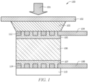
- the ultrasonic gas detector 100 comprises a piezoelectric element 106 operable to convert the pressure of sound waves from mechanical energy into electric signal.
- the ultrasonic sound waves coming from the environment are illustrated by the arrow 101.
- the ultrasonic detector 100 further comprises a protective cover 102, a hot melt adhesive 103 (which may be used as an acoustic filler), one or more perforated metal electrodes 104 and 108 with openings (holes and slots) 112 and 114 filled with solder, one or more layers of solder 105 and 107, the piezoelectric sensing element 106 comprising silver electrodes, and a support 110.
- the protective cover 102 comprises a low density material, such as Polytetrafluoroethylene (PTFE), polyethylene (PE), or another low density material.
- PTFE Polytetrafluoroethylene
- PE polyethylene
- One or more of the described elements may be attached to one another with adhesive.
- the piezoelectric element 106 is soldered to the perforated metal electrodes 104 and 108 that connect it to an electronic circuit. Perforation of the metal electrode(s) 104 and 108 allows the electrode(s) 104 and 108 to be attached to the piezoelectric element 106 in a way that provides stability for a broad range of temperatures, as these holes 112 and 114 are filled with solder material. Perforation also simplifies the soldering process, as the solder paste 105 and 107 penetrates easily through the perforated holes 112 and 114 and stops the silver electrode(s) of the piezoelectric element 106 from being dissolved in the solder during the soldering process.
- the hot melt adhesive 103 is used as acoustic filler for the space between the ultrasound exposed area of the piezoelectric element 106 and the protective cover 102.
- the molten hot melt material solidifies on contact with the piezoelectric element and casing, stopping leakage into the housing while maintaining excellent acoustic and waterproof sealing properties. Hot melt material cools in a matter of minutes allowing for a simpler manufacturing process.
- a piezoelectric element may be conductively connected to metal electrodes both with conductive glue and soldering. Applicants have discovered that perforated metal electrodes 104 and 108 soldered to the piezoelectric element 106 can survive multiple temperature shocks, which may relate to or demonstrate aging of device and the influence of the environment on it.
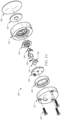
- the ultrasonic detector 200 may be similar to the ultrasonic detector 100 of FIG. 1 , wherein the ultrasonic detector 200 may comprise a piezoelectric element 206, a protective cover 202, a hot melt adhesive 203 (which may be used as an acoustic filler), one or more perforated metal electrodes 204 and 208 and a support 210, wherein these elements may be similar to the piezoelectric element 106, protective cover 102, hot melt adhesive 103, perforated metal electrodes 104 and 108, and support 110 described in FIG. 1 .
- the ultrasonic detector 200 comprises one or more casing elements 220 and 222 operable to enclose and house the other elements of the ultrasonic detector 200.
- the casing elements 220 and 222 may comprise a metal material and may be held together by one or more screws 224.
- the ultrasonic detector 200 may comprise a printed circuit board (PCB) 230 operable to receive ultrasonic data from the piezoelectric element 206 and electrodes 204 and 208, wherein the electrodes 204 and 208 may connect to, or contact, the PCB 230.
- the ultrasonic detector 200 comprises supporting elements and insulating elements for supporting and insulating the other elements of the ultrasonic detector 200.
- a foam support 226 may be located within the casing elements 200 and 222.
- an insulator 228 (which may be made of a plastic material) is located in proximity to the electrodes 204 and 208, and is operable to prevent shorting between the metal electrodes 204 and 208 and the metal casing elements 220 and 222.
- Soldering of the electrode(s) to the piezoelectric element may be done at temperature of +280 degrees Celsius (C) for up to 4 seconds. This temperature is beneath the Curie temperature of the piezoelectric material, which is +300 degrees C, and this protects the piezoelectric element from losing its sensitivity.
- Using of a low density material as front protective layer of the ultrasonic sensor allows stopping bimetallic corrosion between the metal body of ultrasonic sensor and the metal body of the instrument enclosure, as those two might be made from different metals.
- the protective cover with an O-ring above it seals the ultrasonic sensor inside the main instrument enclosure.
- Some embodiments of the disclosure may include one or more methods for forming an ultrasonic detector.
- the method may comprise providing a piezoelectric element operable to convert the pressure of sound waves from mechanical energy into electric signal; soldering the piezoelectric element to one or more perforated metal electrodes with holes and slots filled with the solder material; attaching a protective cover comprising a low density material operable to allow sound to pass through to the piezoelectric element; attaching the one or more electrodes to a printed circuit board; and assembling at least some of the above elements within a casing.
- Attaching the protective cover comprises attaching a hot melt adhesive between the protective cover and the piezoelectric element.
- the hot melt adhesive may be used as an acoustic filler.
- the method may further comprise providing one or more support elements within the casing for supporting the elements and preventing movement of the elements within the casing.
- the method further comprises providing one or more insulating elements to insulate the metal electrodes from contacting the casing.
- the ultrasonic detector may further comprise a printed circuit board (PCB) operable to receive ultrasonic data from the piezoelectric element and electrodes, wherein the electrodes connect to, or contact, the PCB.
- PCB printed circuit board
- the casing elements are held together by one or more screws.
- the piezoelectric element is soldered to the perforated metal electrodes, and the metal electrodes connect the piezoelectric element to an electronic circuit.
- the solder material fills the perforations, holes and slots, of the metal electrodes, allowing the electrodes to be attached to the piezoelectric element in a way that provides stability for a broad range of temperatures.
- the hot melt adhesive is used as acoustic filler for the space between the ultrasound exposed area of the piezoelectric element and the protective cover.
- the molten hot melt material freezes on contact with the piezoelectric element and casing stopping leakage into the housing while maintain excellent acoustic and waterproof sealing properties.
- the protective cover comprises one of Polytetrafluoroethylene (PTFE) and polyethylene (PE).
- PTFE Polytetrafluoroethylene
- PE polyethylene
- the low density material of the protective cover is resistant to many aggressive chemicals in a broad temperature range but allows the ultrasound waves to pass through to the piezoelectric element.
- soldering of the electrode(s) to the piezoelectric element is done at temperature of +280 degrees Celsius (C) for up to 4 seconds.
- the ultrasonic detector further comprises one or more layers of adhesive operable to attach one or more of the above elements.
Landscapes
- Physics & Mathematics (AREA)
- General Physics & Mathematics (AREA)
- Investigating Or Analyzing Materials By The Use Of Ultrasonic Waves (AREA)
- Transducers For Ultrasonic Waves (AREA)
Description
- This application claims priority to International Application No.
PCT/LTS2016/015517 (entitled PIEZOELECTRIC ULTRASONIC DETECTOR filed January 29, 2016 U.S. Provisional Patent Application Serial No. 62/111,407 (entitled PIEZOELECTRIC ULTRASONIC DETECTOR filed February 3, 2015 - Leakage of gas from gas installations, pipe lines and their components might be very dangerous for the environment, and human and animal health, especially if the gas is toxic, flammable or corrosive. If such gas leak happens e.g. as an accident, it is important to detect the leak as soon as possible. The leak may also be quantitatively measured to determine if the leak is above certain threshold value for alarm, and also to determine any further steps that should be taken to stop the leak. Therefore, gas detectors may be used in areas where this potential for gas leaks.
- Reference may be made to
WO 2014/125242 A2 , which relates to a sound sensor in the form of a compression assembly for detecting airborne sound, and comprises a piezoelectric crystal transducer, an electrode and a low density environmental seal. - The present invention relates to an ultrasonic gas detector according to claim 1 and to a method for forming an ultrasonic gas detector according to claim 11.
- The present invention is defined by the independent claims, to which reference should now be made. Specific embodiments are defined in the dependent claims. For a more complete understanding of the present disclosure, reference is now made to the following brief description, taken in connection with the accompanying drawings and detailed description, wherein like reference numerals represent like parts.
-
FIG. 1 illustrates a cross-sectional view of an ultrasonic detector according to an embodiment of the disclosure; -
FIG. 2A illustrates an exploded view of an ultrasonic detector according to an embodiment of the disclosure; and -
FIGS. 2B illustrate another exploded view of an ultrasonic detector according to an embodiment of the disclosure. - It should be understood at the outset that although illustrative implementations of one or more embodiments are illustrated below, the disclosed systems and methods may be implemented using any number of techniques, whether currently known or not yet in existence. The disclosure should in no way be limited to the illustrative implementations, drawings, and techniques illustrated below, but may be modified within the scope of the appended claims.
- The following brief definition of terms shall apply throughout the application:
- The term "comprising" means including but not limited to, and should be interpreted in the manner it is typically used in the patent context;
- The phrases "in one embodiment," "according to one embodiment," and the like generally mean that the particular feature, structure, or characteristic following the phrase may be included in at least one embodiment of the present invention, and may be included in more than one embodiment of the present invention (importantly, such phrases do not necessarily refer to the same embodiment);
- If the specification describes something as "exemplary" or an "example," it should be understood that refers to a non-exclusive example;
- The terms "about" or approximately" or the like, when used with a number, may mean that specific number, or alternatively, a range in proximity to the specific number, as understood by persons of skill in the art field; and
- If the specification states a component or feature "may," "can," "could," "should," "would," "preferably," "possibly," "typically," "optionally," "for example," "often," or "might" (or other such language) be included or have a characteristic, that particular component or feature is not required to be included or to have the characteristic. Such component or feature may be optionally included in some embodiments, or it may be excluded.
- Leakage of gas from gas installations, pipe lines and their components might be very dangerous for the environment, as well as human and animal health, especially if the gas is toxic, flammable or corrosive. If such a gas leak happens, for example as an accident, it needs to be detected as soon as possible, and quantitatively measured to determine if the leak of gas is above an alarm threshold value. If the gas is above the threshold, the alarm may sound, allowing for safe evacuation. Additionally, some part of the gas installation may need to be switched off and insulated in order to stop the gas leak.
- In some cases, gas leakages from pressurized source produce sound, which typically have frequencies in audible and ultrasonic range. An ultrasonic detector may be capable of detecting this ultrasound (at ultrasonic frequency), and therefore detect the gas leak. An ultrasonic detector would signal the level of this ultrasound, thereby triggering an alarm if the ultrasound level is above certain, preset threshold.
- Referring to
FIG. 1 , anultrasonic detector 100 is described. Theultrasonic gas detector 100 comprises apiezoelectric element 106 operable to convert the pressure of sound waves from mechanical energy into electric signal. The ultrasonic sound waves coming from the environment are illustrated by thearrow 101. Theultrasonic detector 100 further comprises aprotective cover 102, a hot melt adhesive 103 (which may be used as an acoustic filler), one or moreperforated metal electrodes solder piezoelectric sensing element 106 comprising silver electrodes, and asupport 110. Theprotective cover 102 comprises a low density material, such as Polytetrafluoroethylene (PTFE), polyethylene (PE), or another low density material. One or more of the described elements may be attached to one another with adhesive. - The
piezoelectric element 106 is soldered to theperforated metal electrodes piezoelectric element 106 in a way that provides stability for a broad range of temperatures, as theseholes solder paste holes piezoelectric element 106 from being dissolved in the solder during the soldering process. Thehot melt adhesive 103 is used as acoustic filler for the space between the ultrasound exposed area of thepiezoelectric element 106 and theprotective cover 102. The molten hot melt material solidifies on contact with the piezoelectric element and casing, stopping leakage into the housing while maintaining excellent acoustic and waterproof sealing properties. Hot melt material cools in a matter of minutes allowing for a simpler manufacturing process. - Using the low density material for the
protective cover 102 for theultrasonic detector 100 is beneficial as it is resistant to many aggressive chemicals in a broad temperature range but allows the ultrasound waves to pass through to thepiezoelectric element 106. In other applications, a piezoelectric element may be conductively connected to metal electrodes both with conductive glue and soldering. Applicants have discovered thatperforated metal electrodes piezoelectric element 106 can survive multiple temperature shocks, which may relate to or demonstrate aging of device and the influence of the environment on it. - Referring now to
FIGS. 2A-2B , two exploded views of anultrasonic detector 200 are shown. Theultrasonic detector 200 may be similar to theultrasonic detector 100 ofFIG. 1 , wherein theultrasonic detector 200 may comprise apiezoelectric element 206, aprotective cover 202, a hot melt adhesive 203 (which may be used as an acoustic filler), one or moreperforated metal electrodes support 210, wherein these elements may be similar to thepiezoelectric element 106,protective cover 102, hot melt adhesive 103, perforatedmetal electrodes support 110 described inFIG. 1 . - Additionally, the
ultrasonic detector 200 comprises one ormore casing elements ultrasonic detector 200. In some embodiments, thecasing elements more screws 224. In some embodiments, theultrasonic detector 200 may comprise a printed circuit board (PCB) 230 operable to receive ultrasonic data from thepiezoelectric element 206 andelectrodes electrodes PCB 230. Theultrasonic detector 200 comprises supporting elements and insulating elements for supporting and insulating the other elements of theultrasonic detector 200. For example, afoam support 226 may be located within thecasing elements electrodes metal electrodes metal casing elements - Soldering of the electrode(s) to the piezoelectric element may be done at temperature of +280 degrees Celsius (C) for up to 4 seconds. This temperature is beneath the Curie temperature of the piezoelectric material, which is +300 degrees C, and this protects the piezoelectric element from losing its sensitivity.
- Using of a low density material as front protective layer of the ultrasonic sensor allows stopping bimetallic corrosion between the metal body of ultrasonic sensor and the metal body of the instrument enclosure, as those two might be made from different metals. The protective cover with an O-ring above it seals the ultrasonic sensor inside the main instrument enclosure.
- Some embodiments of the disclosure may include one or more methods for forming an ultrasonic detector. The method may comprise providing a piezoelectric element operable to convert the pressure of sound waves from mechanical energy into electric signal; soldering the piezoelectric element to one or more perforated metal electrodes with holes and slots filled with the solder material; attaching a protective cover comprising a low density material operable to allow sound to pass through to the piezoelectric element; attaching the one or more electrodes to a printed circuit board; and assembling at least some of the above elements within a casing.
- Attaching the protective cover comprises attaching a hot melt adhesive between the protective cover and the piezoelectric element. The hot melt adhesive may be used as an acoustic filler. In some embodiments, the method may further comprise providing one or more support elements within the casing for supporting the elements and preventing movement of the elements within the casing. The method further comprises providing one or more insulating elements to insulate the metal electrodes from contacting the casing.
- In some embodiments, the ultrasonic detector may further comprise a printed circuit board (PCB) operable to receive ultrasonic data from the piezoelectric element and electrodes, wherein the electrodes connect to, or contact, the PCB.
- In some embodiments, the casing elements are held together by one or more screws. The piezoelectric element is soldered to the perforated metal electrodes, and the metal electrodes connect the piezoelectric element to an electronic circuit. In some embodiments, the solder material fills the perforations, holes and slots, of the metal electrodes, allowing the electrodes to be attached to the piezoelectric element in a way that provides stability for a broad range of temperatures. In some embodiments, the hot melt adhesive is used as acoustic filler for the space between the ultrasound exposed area of the piezoelectric element and the protective cover. In some embodiments, the molten hot melt material freezes on contact with the piezoelectric element and casing stopping leakage into the housing while maintain excellent acoustic and waterproof sealing properties. In some embodiments, the protective cover comprises one of Polytetrafluoroethylene (PTFE) and polyethylene (PE). The low density material of the protective cover is resistant to many aggressive chemicals in a broad temperature range but allows the ultrasound waves to pass through to the piezoelectric element. In some embodiments, soldering of the electrode(s) to the piezoelectric element is done at temperature of +280 degrees Celsius (C) for up to 4 seconds. The ultrasonic detector further comprises one or more layers of adhesive operable to attach one or more of the above elements.
- While various embodiments in accordance with the principles disclosed herein have been shown and described above, modifications thereof may be made by one skilled in the art. The embodiments described herein are representative only and are not intended to be limiting. Many variations, combinations, and modifications are possible and are within the scope of the disclosure. Alternative embodiments that result from combining, integrating, and/or omitting features of the embodiment(s) are also within the scope of the disclosure. Accordingly, the scope of protection is not limited by the description set out above, but is defined by the claims which follow. Furthermore, any advantages and features described above may relate to specific embodiments, but shall not limit the application of such issued claims to processes and structures accomplishing any or all of the above advantages or having any or all of the above features.
- Use of broader terms such as comprises, includes, and having should be understood to provide support for narrower terms such as consisting of, consisting essentially of, and comprised substantially of. Use of the term "optionally," "may," "might," "possibly," and the like with respect to any element of an embodiment means that the element is not required, or alternatively, the element is required, both alternatives being within the scope of the embodiment(s). Also, references to examples are merely provided for illustrative purposes, and are not intended to be exclusive.
- present examples are to be considered as illustrative and not restrictive, and the intention is not to be limited to the details given herein. For example, the various elements or components may be combined or integrated in another system or certain features may be omitted or not implemented.
- Also, techniques, systems, subsystems, and methods described and illustrated in the various embodiments as discrete or separate may be combined or integrated with other systems, modules, techniques, or methods without departing from the scope of the present disclosure. Other items shown or discussed as directly coupled or communicating with each other may be indirectly coupled or communicating through some interface, device, or intermediate component, whether electrically, mechanically, or otherwise. The invention is solely defined by the appended claims.
Claims (13)
- An ultrasonic gas detector (100) comprising:a piezoelectric element (106) configured to convert the pressure of sound waves from mechanical energy into electric signal;one or more perforated metal electrodes (104 and 108) located proximate to the piezoelectric element (106);one or more layers of solder (105 and 107) configured to attach the one or more perforated metal electrodes (104 and 108) to the piezoelectric element (106);a protective cover (102) comprising a low density material, the protective cover located on a first surface of the combined piezoelectric element (106) and one or more perforated metal electrodes (104 and 108);a hot melt adhesive (103) configured to attach the protective cover (102) to the first surface of the combined piezoelectric element (106) and one or more perforated metal electrodes (104 and 108);one or more support elements (110) located proximate to the combined piezoelectric element (106) and one or more perforated metal electrodes (104 and 108), wherein the ultrasonic gas detector is configured to detect an ultrasound;one or more casing elements (220 and 222) operable to enclose and house the other elements of the ultrasonic detector (100); andan insulator (228) located in proximity to the one or more perforated metal electrodes (104 and 108), and operable to prevent shorting between the one or more perforated metal electrodes (104 and 108) and the one or more casing elements (220 and 222).
- The ultrasonic gas detector (100) of claim 1 further comprising:
a printed circuit board (PCB) (230) operable to receive ultrasonic data from the piezoelectric element (106) and the one or more perforated metal electrodes (104 and 108), wherein the one or more perforated metal electrodes (104 and 108) connect to, or contact, the PCB (230). - The ultrasonic gas detector (100) of claim 1, wherein the piezoelectric element (106) is soldered to the one or more perforated metal electrodes (104 and 108), and wherein the one or more perforated metal electrodes (104 and 108) connect the piezoelectric element (106) to an electronic circuit
- The ultrasonic gas detector (100) of claim 1, wherein the one or more perforated metal electrodes (104 and 108) comprise a plurality of openings (112 and 114).
- The ultrasonic gas detector (100) of claim 4, wherein the solder material fills the openings (112 and 114) of the one or more perforated metal electrodes (104 and 108), allowing the one or more perforated metal electrodes (104 and 108) to be attached to the piezoelectric element (106) in a way that provides stability for a broad range of temperatures.
- The ultrasonic gas detector (100) of claim 1, wherein the hot melt adhesive (103) is used as acoustic filler for the space between the ultrasound exposed area of the piezoelectric element (106) and the protective cover (102).
- The ultrasonic gas detector (100) of claim 5, wherein the molten hot melt adhesive (103) solidifies on contact with the piezoelectric element (106) and one or more casing elements (220 and 222), stopping leakage into the housing while maintain excellent acoustic and waterproof sealing properties.
- The ultrasonic gas detector (100) of claim 1, wherein the protective cover (102) comprises one of Polytetrafluoroethylene, PTFE, and polyethylene, PE.
- The ultrasonic gas detector (100) of claim 1, wherein the low density material of the protective cover (102) is resistant to many aggressive chemicals in a broad temperature range but allows the ultrasound waves to pass through to the piezoelectric element.
- The ultrasonic gas detector (100) of claim 1, wherein soldering of the one or more perforated metal electrode(s) (104 and 108) to the piezoelectric element (106) is done at temperature of 280 degrees Celsius (°C) for up to 4 seconds.
- A method for forming an ultrasonic gas detector (100) comprising:providing a piezoelectric element (106) operable to convert the pressure of sound waves from mechanical energy into electric signal;soldering the piezoelectric element (106) to one or more perforated metal electrodes (104 and 108);attaching a protective cover (102), with a hot melt adhesive (103), to the piezoelectric element (106), wherein the protective cover (102) comprises a low density material and is operable to allow sound to pass through to the piezoelectric element (106);attaching the one or more perforated metal electrodes (104 and 108) to a printed circuit board (230); and
assembling at least some of the above elements within a casing (220), wherein the ultrasonic gas detector is configured to detect an ultrasound,wherein the method further comprises providing one or more insulating elements to insulate the one or more perforated metal electrodes (104 and 108) from contacting the casing (220). - The method of claim 11 further comprising providing one or more support elements (110) within the casing (220) for supporting the elements and preventing movement of the elements within the casing (220).
- The method of claim 11, wherein attaching the protective cover (102) comprises attaching a hot melt adhesive (103) between the protective cover (102) and the piezoelectric element (106), wherein the hot melt adhesive (103) is used as an acoustic filler.
Applications Claiming Priority (3)
| Application Number | Priority Date | Filing Date | Title |
|---|---|---|---|
| US201562111407P | 2015-02-03 | 2015-02-03 | |
| EP16703702.7A EP3254071B1 (en) | 2015-02-03 | 2016-01-29 | Piezoelectric ultrasonic detector |
| PCT/US2016/015517 WO2016126533A1 (en) | 2015-02-03 | 2016-01-29 | Piezoelectric ultrasonic detector |
Related Parent Applications (2)
| Application Number | Title | Priority Date | Filing Date |
|---|---|---|---|
| EP16703702.7A Division-Into EP3254071B1 (en) | 2015-02-03 | 2016-01-29 | Piezoelectric ultrasonic detector |
| EP16703702.7A Division EP3254071B1 (en) | 2015-02-03 | 2016-01-29 | Piezoelectric ultrasonic detector |
Publications (2)
| Publication Number | Publication Date |
|---|---|
| EP4089378A1 EP4089378A1 (en) | 2022-11-16 |
| EP4089378B1 true EP4089378B1 (en) | 2024-11-20 |
Family
ID=55315790
Family Applications (2)
| Application Number | Title | Priority Date | Filing Date |
|---|---|---|---|
| EP22177659.4A Active EP4089378B1 (en) | 2015-02-03 | 2016-01-29 | Piezoelectric ultrasonic gas detector |
| EP16703702.7A Active EP3254071B1 (en) | 2015-02-03 | 2016-01-29 | Piezoelectric ultrasonic detector |
Family Applications After (1)
| Application Number | Title | Priority Date | Filing Date |
|---|---|---|---|
| EP16703702.7A Active EP3254071B1 (en) | 2015-02-03 | 2016-01-29 | Piezoelectric ultrasonic detector |
Country Status (6)
| Country | Link |
|---|---|
| US (1) | US10551264B2 (en) |
| EP (2) | EP4089378B1 (en) |
| CN (1) | CN107209053B (en) |
| AU (1) | AU2016215624B2 (en) |
| CA (1) | CA2975256C (en) |
| WO (1) | WO2016126533A1 (en) |
Families Citing this family (2)
| Publication number | Priority date | Publication date | Assignee | Title |
|---|---|---|---|---|
| CA2975256C (en) | 2015-02-03 | 2024-02-20 | Honeywell International Inc. | Piezoelectric ultrasonic detector |
| EP3339854B1 (en) * | 2016-12-21 | 2021-02-03 | Honeywell International Inc. | Explosion proof piezoelectric ultrasonic detector |
Family Cites Families (21)
| Publication number | Priority date | Publication date | Assignee | Title |
|---|---|---|---|---|
| US6669690B1 (en) * | 1995-04-06 | 2003-12-30 | Olympus Optical Co., Ltd. | Ultrasound treatment system |
| KR0165517B1 (en) * | 1996-03-07 | 1999-05-01 | 김광호 | Vibration detecting sensor |
| EP0825585B1 (en) * | 1996-08-21 | 2005-07-20 | Volkswagen Aktiengesellschaft | Apparatus for determination of distances to objects |
| JP2000176262A (en) * | 1998-12-11 | 2000-06-27 | Daikin Ind Ltd | Porous materials, air filter media, air filter units and support materials for air filter media |
| JP2002228742A (en) * | 2001-01-31 | 2002-08-14 | Ngk Spark Plug Co Ltd | Ultrasonic sensor |
| CN100435741C (en) * | 2002-12-11 | 2008-11-26 | 皇家飞利浦电子股份有限公司 | Miniaturized ultrasonic transducer |
| DE10259949A1 (en) * | 2002-12-20 | 2004-07-01 | Robert Bosch Gmbh | piezo actuator |
| GB0813014D0 (en) * | 2008-07-16 | 2008-08-20 | Groveley Detection Ltd | Detector and methods of detecting |
| AU2013206304B2 (en) | 2008-07-16 | 2015-01-22 | Rosemount Measurement Limited | Detector and methods of detecting |
| JP2010048749A (en) * | 2008-08-25 | 2010-03-04 | Kyocera Corp | Vibration sensor |
| CN102639969A (en) | 2009-11-19 | 2012-08-15 | 松下电器产业株式会社 | Ultrasonic flowmeter |
| PL2569604T3 (en) * | 2010-05-12 | 2020-04-30 | Diehl Metering Gmbh | Ultrasound flowmeter |
| CN202382752U (en) | 2011-12-26 | 2012-08-15 | 上官明禹 | An anti-corrosion ultrasonic sensor |
| JP6186696B2 (en) * | 2012-10-25 | 2017-08-30 | セイコーエプソン株式会社 | Ultrasonic measuring device, head unit, probe and diagnostic device |
| US8982647B2 (en) * | 2012-11-14 | 2015-03-17 | Crossbar, Inc. | Resistive random access memory equalization and sensing |
| GB2515718B (en) * | 2013-02-14 | 2015-09-09 | Roger Thomas Hurrey | Piezoelectric Sensor Compression Assembly, Self-Test and Background Sensitivity |
| WO2014133211A1 (en) * | 2013-02-28 | 2014-09-04 | 알피니언메디칼시스템 주식회사 | Ultrasonic transducer and manufacturing method therefor |
| CN203568132U (en) * | 2013-10-14 | 2014-04-30 | 上海晶纯实业有限公司 | Anti-corrosion PE composite polytetrafluoroethylene gasket |
| KR102184454B1 (en) * | 2014-08-25 | 2020-11-30 | 삼성전자주식회사 | Ultrasonic transducer and method of manufacturing ultrasonic transducer |
| CA2975256C (en) | 2015-02-03 | 2024-02-20 | Honeywell International Inc. | Piezoelectric ultrasonic detector |
| EP3339854B1 (en) | 2016-12-21 | 2021-02-03 | Honeywell International Inc. | Explosion proof piezoelectric ultrasonic detector |
-
2016
- 2016-01-29 CA CA2975256A patent/CA2975256C/en active Active
- 2016-01-29 US US15/548,470 patent/US10551264B2/en active Active
- 2016-01-29 CN CN201680008464.4A patent/CN107209053B/en active Active
- 2016-01-29 EP EP22177659.4A patent/EP4089378B1/en active Active
- 2016-01-29 EP EP16703702.7A patent/EP3254071B1/en active Active
- 2016-01-29 AU AU2016215624A patent/AU2016215624B2/en active Active
- 2016-01-29 WO PCT/US2016/015517 patent/WO2016126533A1/en not_active Ceased
Also Published As
| Publication number | Publication date |
|---|---|
| CN107209053A (en) | 2017-09-26 |
| AU2016215624B2 (en) | 2020-11-12 |
| CN107209053B (en) | 2021-01-08 |
| EP3254071A1 (en) | 2017-12-13 |
| US10551264B2 (en) | 2020-02-04 |
| EP3254071B1 (en) | 2022-08-03 |
| AU2016215624A1 (en) | 2017-08-10 |
| EP4089378A1 (en) | 2022-11-16 |
| CA2975256C (en) | 2024-02-20 |
| CA2975256A1 (en) | 2016-08-11 |
| WO2016126533A1 (en) | 2016-08-11 |
| AU2016215624A2 (en) | 2017-09-28 |
| US20180017458A1 (en) | 2018-01-18 |
Similar Documents
| Publication | Publication Date | Title |
|---|---|---|
| JP5973357B2 (en) | Pressure detection unit and method for manufacturing pressure detection unit | |
| EP3339854B1 (en) | Explosion proof piezoelectric ultrasonic detector | |
| EP2414788B1 (en) | Flow meter unit with water-tight casing | |
| US9995621B2 (en) | Sound sensor | |
| CN104240448A (en) | Self-Contained, Buoyant, and Water-Tight Wireless Flood Detector | |
| US20150288069A1 (en) | Protection apparatus for a hollow conductor and method for producing a protection apparatus | |
| RU2279650C2 (en) | Module with pressure gage | |
| EP3254071B1 (en) | Piezoelectric ultrasonic detector | |
| KR20200066678A (en) | Pressure sensor | |
| US10818577B2 (en) | Microphone packaging for a portable communication device | |
| US20160320442A1 (en) | Electric arc detection | |
| JP6634201B2 (en) | Liquid level sensor | |
| US11597647B2 (en) | Packaged die and assembling method | |
| CN109313097A (en) | Pressure Sensor | |
| AU2009212091A1 (en) | Degradation sensor | |
| JP2010008314A (en) | Temperature sensor | |
| KR102819072B1 (en) | Acoustic camera equipped with explosion-proof or waterproof means | |
| JP2018091795A (en) | Method for detecting fluid leak from piping structure, piping structure and construction method | |
| JP2009222460A (en) | Pressure sensor | |
| CN116794225A (en) | Gas detection device and gas detection probe | |
| KR20170075603A (en) | water detection apparatus and portable device including the same |
Legal Events
| Date | Code | Title | Description |
|---|---|---|---|
| PUAI | Public reference made under article 153(3) epc to a published international application that has entered the european phase |
Free format text: ORIGINAL CODE: 0009012 |
|
| STAA | Information on the status of an ep patent application or granted ep patent |
Free format text: STATUS: THE APPLICATION HAS BEEN PUBLISHED |
|
| AC | Divisional application: reference to earlier application |
Ref document number: 3254071 Country of ref document: EP Kind code of ref document: P |
|
| AK | Designated contracting states |
Kind code of ref document: A1 Designated state(s): AL AT BE BG CH CY CZ DE DK EE ES FI FR GB GR HR HU IE IS IT LI LT LU LV MC MK MT NL NO PL PT RO RS SE SI SK SM TR |
|
| STAA | Information on the status of an ep patent application or granted ep patent |
Free format text: STATUS: REQUEST FOR EXAMINATION WAS MADE |
|
| 17P | Request for examination filed |
Effective date: 20230512 |
|
| RBV | Designated contracting states (corrected) |
Designated state(s): AL AT BE BG CH CY CZ DE DK EE ES FI FR GB GR HR HU IE IS IT LI LT LU LV MC MK MT NL NO PL PT RO RS SE SI SK SM TR |
|
| GRAP | Despatch of communication of intention to grant a patent |
Free format text: ORIGINAL CODE: EPIDOSNIGR1 |
|
| STAA | Information on the status of an ep patent application or granted ep patent |
Free format text: STATUS: GRANT OF PATENT IS INTENDED |
|
| RIC1 | Information provided on ipc code assigned before grant |
Ipc: G01M 3/24 20060101ALI20240530BHEP Ipc: G01L 9/08 20060101ALI20240530BHEP Ipc: G01H 11/08 20060101AFI20240530BHEP |
|
| INTG | Intention to grant announced |
Effective date: 20240618 |
|
| GRAS | Grant fee paid |
Free format text: ORIGINAL CODE: EPIDOSNIGR3 |
|
| GRAA | (expected) grant |
Free format text: ORIGINAL CODE: 0009210 |
|
| STAA | Information on the status of an ep patent application or granted ep patent |
Free format text: STATUS: THE PATENT HAS BEEN GRANTED |
|
| AC | Divisional application: reference to earlier application |
Ref document number: 3254071 Country of ref document: EP Kind code of ref document: P |
|
| AK | Designated contracting states |
Kind code of ref document: B1 Designated state(s): AL AT BE BG CH CY CZ DE DK EE ES FI FR GB GR HR HU IE IS IT LI LT LU LV MC MK MT NL NO PL PT RO RS SE SI SK SM TR |
|
| REG | Reference to a national code |
Ref country code: GB Ref legal event code: FG4D |
|
| REG | Reference to a national code |
Ref country code: CH Ref legal event code: EP |
|
| REG | Reference to a national code |
Ref country code: DE Ref legal event code: R096 Ref document number: 602016090371 Country of ref document: DE |
|
| REG | Reference to a national code |
Ref country code: IE Ref legal event code: FG4D |
|
| REG | Reference to a national code |
Ref country code: LT Ref legal event code: MG9D |
|
| REG | Reference to a national code |
Ref country code: NL Ref legal event code: MP Effective date: 20241120 |
|
| PG25 | Lapsed in a contracting state [announced via postgrant information from national office to epo] |
Ref country code: HR Free format text: LAPSE BECAUSE OF FAILURE TO SUBMIT A TRANSLATION OF THE DESCRIPTION OR TO PAY THE FEE WITHIN THE PRESCRIBED TIME-LIMIT Effective date: 20241120 Ref country code: IS Free format text: LAPSE BECAUSE OF FAILURE TO SUBMIT A TRANSLATION OF THE DESCRIPTION OR TO PAY THE FEE WITHIN THE PRESCRIBED TIME-LIMIT Effective date: 20250320 Ref country code: PT Free format text: LAPSE BECAUSE OF FAILURE TO SUBMIT A TRANSLATION OF THE DESCRIPTION OR TO PAY THE FEE WITHIN THE PRESCRIBED TIME-LIMIT Effective date: 20250320 |
|
| PG25 | Lapsed in a contracting state [announced via postgrant information from national office to epo] |
Ref country code: NL Free format text: LAPSE BECAUSE OF FAILURE TO SUBMIT A TRANSLATION OF THE DESCRIPTION OR TO PAY THE FEE WITHIN THE PRESCRIBED TIME-LIMIT Effective date: 20241120 Ref country code: FI Free format text: LAPSE BECAUSE OF FAILURE TO SUBMIT A TRANSLATION OF THE DESCRIPTION OR TO PAY THE FEE WITHIN THE PRESCRIBED TIME-LIMIT Effective date: 20241120 |
|
| REG | Reference to a national code |
Ref country code: AT Ref legal event code: MK05 Ref document number: 1743943 Country of ref document: AT Kind code of ref document: T Effective date: 20241120 |
|
| PG25 | Lapsed in a contracting state [announced via postgrant information from national office to epo] |
Ref country code: BG Free format text: LAPSE BECAUSE OF FAILURE TO SUBMIT A TRANSLATION OF THE DESCRIPTION OR TO PAY THE FEE WITHIN THE PRESCRIBED TIME-LIMIT Effective date: 20241120 |
|
| PG25 | Lapsed in a contracting state [announced via postgrant information from national office to epo] |
Ref country code: ES Free format text: LAPSE BECAUSE OF FAILURE TO SUBMIT A TRANSLATION OF THE DESCRIPTION OR TO PAY THE FEE WITHIN THE PRESCRIBED TIME-LIMIT Effective date: 20241120 |
|
| PG25 | Lapsed in a contracting state [announced via postgrant information from national office to epo] |
Ref country code: NO Free format text: LAPSE BECAUSE OF FAILURE TO SUBMIT A TRANSLATION OF THE DESCRIPTION OR TO PAY THE FEE WITHIN THE PRESCRIBED TIME-LIMIT Effective date: 20250220 |
|
| PG25 | Lapsed in a contracting state [announced via postgrant information from national office to epo] |
Ref country code: AT Free format text: LAPSE BECAUSE OF FAILURE TO SUBMIT A TRANSLATION OF THE DESCRIPTION OR TO PAY THE FEE WITHIN THE PRESCRIBED TIME-LIMIT Effective date: 20241120 Ref country code: GR Free format text: LAPSE BECAUSE OF FAILURE TO SUBMIT A TRANSLATION OF THE DESCRIPTION OR TO PAY THE FEE WITHIN THE PRESCRIBED TIME-LIMIT Effective date: 20250221 Ref country code: LV Free format text: LAPSE BECAUSE OF FAILURE TO SUBMIT A TRANSLATION OF THE DESCRIPTION OR TO PAY THE FEE WITHIN THE PRESCRIBED TIME-LIMIT Effective date: 20241120 |
|
| PG25 | Lapsed in a contracting state [announced via postgrant information from national office to epo] |
Ref country code: PL Free format text: LAPSE BECAUSE OF FAILURE TO SUBMIT A TRANSLATION OF THE DESCRIPTION OR TO PAY THE FEE WITHIN THE PRESCRIBED TIME-LIMIT Effective date: 20241120 |
|
| PG25 | Lapsed in a contracting state [announced via postgrant information from national office to epo] |
Ref country code: RS Free format text: LAPSE BECAUSE OF FAILURE TO SUBMIT A TRANSLATION OF THE DESCRIPTION OR TO PAY THE FEE WITHIN THE PRESCRIBED TIME-LIMIT Effective date: 20250220 |
|
| PG25 | Lapsed in a contracting state [announced via postgrant information from national office to epo] |
Ref country code: SM Free format text: LAPSE BECAUSE OF FAILURE TO SUBMIT A TRANSLATION OF THE DESCRIPTION OR TO PAY THE FEE WITHIN THE PRESCRIBED TIME-LIMIT Effective date: 20241120 |
|
| PG25 | Lapsed in a contracting state [announced via postgrant information from national office to epo] |
Ref country code: DK Free format text: LAPSE BECAUSE OF FAILURE TO SUBMIT A TRANSLATION OF THE DESCRIPTION OR TO PAY THE FEE WITHIN THE PRESCRIBED TIME-LIMIT Effective date: 20241120 |
|
| PG25 | Lapsed in a contracting state [announced via postgrant information from national office to epo] |
Ref country code: EE Free format text: LAPSE BECAUSE OF FAILURE TO SUBMIT A TRANSLATION OF THE DESCRIPTION OR TO PAY THE FEE WITHIN THE PRESCRIBED TIME-LIMIT Effective date: 20241120 |
|
| PG25 | Lapsed in a contracting state [announced via postgrant information from national office to epo] |
Ref country code: RO Free format text: LAPSE BECAUSE OF FAILURE TO SUBMIT A TRANSLATION OF THE DESCRIPTION OR TO PAY THE FEE WITHIN THE PRESCRIBED TIME-LIMIT Effective date: 20241120 |
|
| PG25 | Lapsed in a contracting state [announced via postgrant information from national office to epo] |
Ref country code: SK Free format text: LAPSE BECAUSE OF FAILURE TO SUBMIT A TRANSLATION OF THE DESCRIPTION OR TO PAY THE FEE WITHIN THE PRESCRIBED TIME-LIMIT Effective date: 20241120 |
|
| PG25 | Lapsed in a contracting state [announced via postgrant information from national office to epo] |
Ref country code: CZ Free format text: LAPSE BECAUSE OF FAILURE TO SUBMIT A TRANSLATION OF THE DESCRIPTION OR TO PAY THE FEE WITHIN THE PRESCRIBED TIME-LIMIT Effective date: 20241120 |
|
| PG25 | Lapsed in a contracting state [announced via postgrant information from national office to epo] |
Ref country code: IT Free format text: LAPSE BECAUSE OF FAILURE TO SUBMIT A TRANSLATION OF THE DESCRIPTION OR TO PAY THE FEE WITHIN THE PRESCRIBED TIME-LIMIT Effective date: 20241120 |
|
| REG | Reference to a national code |
Ref country code: DE Ref legal event code: R097 Ref document number: 602016090371 Country of ref document: DE |
|
| REG | Reference to a national code |
Ref country code: CH Ref legal event code: PL |
|
| PG25 | Lapsed in a contracting state [announced via postgrant information from national office to epo] |
Ref country code: SE Free format text: LAPSE BECAUSE OF FAILURE TO SUBMIT A TRANSLATION OF THE DESCRIPTION OR TO PAY THE FEE WITHIN THE PRESCRIBED TIME-LIMIT Effective date: 20241120 |
|
| PG25 | Lapsed in a contracting state [announced via postgrant information from national office to epo] |
Ref country code: LU Free format text: LAPSE BECAUSE OF NON-PAYMENT OF DUE FEES Effective date: 20250129 Ref country code: MC Free format text: LAPSE BECAUSE OF FAILURE TO SUBMIT A TRANSLATION OF THE DESCRIPTION OR TO PAY THE FEE WITHIN THE PRESCRIBED TIME-LIMIT Effective date: 20241120 |
|
| PLBE | No opposition filed within time limit |
Free format text: ORIGINAL CODE: 0009261 |
|
| STAA | Information on the status of an ep patent application or granted ep patent |
Free format text: STATUS: NO OPPOSITION FILED WITHIN TIME LIMIT |
|
| PG25 | Lapsed in a contracting state [announced via postgrant information from national office to epo] |
Ref country code: BE Free format text: LAPSE BECAUSE OF NON-PAYMENT OF DUE FEES Effective date: 20250131 |
|
| PG25 | Lapsed in a contracting state [announced via postgrant information from national office to epo] |
Ref country code: FR Free format text: LAPSE BECAUSE OF NON-PAYMENT OF DUE FEES Effective date: 20250131 |
|
| PG25 | Lapsed in a contracting state [announced via postgrant information from national office to epo] |
Ref country code: CH Free format text: LAPSE BECAUSE OF NON-PAYMENT OF DUE FEES Effective date: 20250131 |
|
| 26N | No opposition filed |
Effective date: 20250821 |
|
| REG | Reference to a national code |
Ref country code: BE Ref legal event code: MM Effective date: 20250131 |
|
| PG25 | Lapsed in a contracting state [announced via postgrant information from national office to epo] |
Ref country code: IE Free format text: LAPSE BECAUSE OF NON-PAYMENT OF DUE FEES Effective date: 20250129 |
|
| PGFP | Annual fee paid to national office [announced via postgrant information from national office to epo] |
Ref country code: GB Payment date: 20260126 Year of fee payment: 11 |
|
| PGFP | Annual fee paid to national office [announced via postgrant information from national office to epo] |
Ref country code: DE Payment date: 20260127 Year of fee payment: 11 |