EP4089031B1 - Verpacktes installationskit, das eine installationsanordnung mit stützbalken als komponenten umfasst - Google Patents
Verpacktes installationskit, das eine installationsanordnung mit stützbalken als komponenten umfasst Download PDFInfo
- Publication number
- EP4089031B1 EP4089031B1 EP22172945.2A EP22172945A EP4089031B1 EP 4089031 B1 EP4089031 B1 EP 4089031B1 EP 22172945 A EP22172945 A EP 22172945A EP 4089031 B1 EP4089031 B1 EP 4089031B1
- Authority
- EP
- European Patent Office
- Prior art keywords
- packaging
- length
- installation kit
- packed
- support beams
- Prior art date
- Legal status (The legal status is an assumption and is not a legal conclusion. Google has not performed a legal analysis and makes no representation as to the accuracy of the status listed.)
- Active
Links
Images



Classifications
-
- B—PERFORMING OPERATIONS; TRANSPORTING
- B65—CONVEYING; PACKING; STORING; HANDLING THIN OR FILAMENTARY MATERIAL
- B65D—CONTAINERS FOR STORAGE OR TRANSPORT OF ARTICLES OR MATERIALS, e.g. BAGS, BARRELS, BOTTLES, BOXES, CANS, CARTONS, CRATES, DRUMS, JARS, TANKS, HOPPERS, FORWARDING CONTAINERS; ACCESSORIES, CLOSURES, OR FITTINGS THEREFOR; PACKAGING ELEMENTS; PACKAGES
- B65D77/00—Packages formed by enclosing articles or materials in preformed containers, e.g. boxes, cartons, sacks or bags
- B65D77/04—Articles or materials enclosed in two or more containers disposed one within another
- B65D77/0413—Articles or materials enclosed in two or more containers disposed one within another the inner and outer containers being rigid or semi-rigid and the outer container being of polygonal cross-section formed by folding or erecting one or more blanks, e.g. carton
-
- B—PERFORMING OPERATIONS; TRANSPORTING
- B65—CONVEYING; PACKING; STORING; HANDLING THIN OR FILAMENTARY MATERIAL
- B65D—CONTAINERS FOR STORAGE OR TRANSPORT OF ARTICLES OR MATERIALS, e.g. BAGS, BARRELS, BOTTLES, BOXES, CANS, CARTONS, CRATES, DRUMS, JARS, TANKS, HOPPERS, FORWARDING CONTAINERS; ACCESSORIES, CLOSURES, OR FITTINGS THEREFOR; PACKAGING ELEMENTS; PACKAGES
- B65D5/00—Rigid or semi-rigid containers of polygonal cross-section, e.g. boxes, cartons or trays, formed by folding or erecting one or more blanks made of paper
- B65D5/02—Rigid or semi-rigid containers of polygonal cross-section, e.g. boxes, cartons or trays, formed by folding or erecting one or more blanks made of paper by folding or erecting a single blank to form a tubular body with or without subsequent folding operations, or the addition of separate elements, to close the ends of the body
- B65D5/0227—Rigid or semi-rigid containers of polygonal cross-section, e.g. boxes, cartons or trays, formed by folding or erecting one or more blanks made of paper by folding or erecting a single blank to form a tubular body with or without subsequent folding operations, or the addition of separate elements, to close the ends of the body with end closures formed by inward folding of flaps and securing them by heat-sealing, by applying adhesive to the flaps or by staples
-
- B—PERFORMING OPERATIONS; TRANSPORTING
- B65—CONVEYING; PACKING; STORING; HANDLING THIN OR FILAMENTARY MATERIAL
- B65D—CONTAINERS FOR STORAGE OR TRANSPORT OF ARTICLES OR MATERIALS, e.g. BAGS, BARRELS, BOTTLES, BOXES, CANS, CARTONS, CRATES, DRUMS, JARS, TANKS, HOPPERS, FORWARDING CONTAINERS; ACCESSORIES, CLOSURES, OR FITTINGS THEREFOR; PACKAGING ELEMENTS; PACKAGES
- B65D5/00—Rigid or semi-rigid containers of polygonal cross-section, e.g. boxes, cartons or trays, formed by folding or erecting one or more blanks made of paper
- B65D5/42—Details of containers or of foldable or erectable container blanks
- B65D5/44—Integral, inserted or attached portions forming internal or external fittings
- B65D5/50—Internal supporting or protecting elements for contents
- B65D5/5028—Elements formed separately from the container body
- B65D5/5035—Paper elements
- B65D5/5047—Blocks
- B65D5/5054—Blocks formed by a plurality of layers contacting each other, e.g. multiple layers of corrugated cardboard
-
- B—PERFORMING OPERATIONS; TRANSPORTING
- B65—CONVEYING; PACKING; STORING; HANDLING THIN OR FILAMENTARY MATERIAL
- B65D—CONTAINERS FOR STORAGE OR TRANSPORT OF ARTICLES OR MATERIALS, e.g. BAGS, BARRELS, BOTTLES, BOXES, CANS, CARTONS, CRATES, DRUMS, JARS, TANKS, HOPPERS, FORWARDING CONTAINERS; ACCESSORIES, CLOSURES, OR FITTINGS THEREFOR; PACKAGING ELEMENTS; PACKAGES
- B65D5/00—Rigid or semi-rigid containers of polygonal cross-section, e.g. boxes, cartons or trays, formed by folding or erecting one or more blanks made of paper
- B65D5/42—Details of containers or of foldable or erectable container blanks
- B65D5/44—Integral, inserted or attached portions forming internal or external fittings
- B65D5/50—Internal supporting or protecting elements for contents
- B65D5/5028—Elements formed separately from the container body
- B65D5/5035—Paper elements
- B65D5/5069—Capping elements, i.e. elements which are located onto one or more ends of the contents, before the contents are inserted into the package
-
- B—PERFORMING OPERATIONS; TRANSPORTING
- B65—CONVEYING; PACKING; STORING; HANDLING THIN OR FILAMENTARY MATERIAL
- B65D—CONTAINERS FOR STORAGE OR TRANSPORT OF ARTICLES OR MATERIALS, e.g. BAGS, BARRELS, BOTTLES, BOXES, CANS, CARTONS, CRATES, DRUMS, JARS, TANKS, HOPPERS, FORWARDING CONTAINERS; ACCESSORIES, CLOSURES, OR FITTINGS THEREFOR; PACKAGING ELEMENTS; PACKAGES
- B65D5/00—Rigid or semi-rigid containers of polygonal cross-section, e.g. boxes, cartons or trays, formed by folding or erecting one or more blanks made of paper
- B65D5/42—Details of containers or of foldable or erectable container blanks
- B65D5/64—Lids
- B65D5/68—Telescope flanged lids
-
- B—PERFORMING OPERATIONS; TRANSPORTING
- B65—CONVEYING; PACKING; STORING; HANDLING THIN OR FILAMENTARY MATERIAL
- B65D—CONTAINERS FOR STORAGE OR TRANSPORT OF ARTICLES OR MATERIALS, e.g. BAGS, BARRELS, BOTTLES, BOXES, CANS, CARTONS, CRATES, DRUMS, JARS, TANKS, HOPPERS, FORWARDING CONTAINERS; ACCESSORIES, CLOSURES, OR FITTINGS THEREFOR; PACKAGING ELEMENTS; PACKAGES
- B65D81/00—Containers, packaging elements, or packages, for contents presenting particular transport or storage problems, or adapted to be used for non-packaging purposes after removal of contents
- B65D81/02—Containers, packaging elements, or packages, for contents presenting particular transport or storage problems, or adapted to be used for non-packaging purposes after removal of contents specially adapted to protect contents from mechanical damage
- B65D81/05—Containers, packaging elements, or packages, for contents presenting particular transport or storage problems, or adapted to be used for non-packaging purposes after removal of contents specially adapted to protect contents from mechanical damage maintaining contents at spaced relation from package walls, or from other contents
- B65D81/107—Containers, packaging elements, or packages, for contents presenting particular transport or storage problems, or adapted to be used for non-packaging purposes after removal of contents specially adapted to protect contents from mechanical damage maintaining contents at spaced relation from package walls, or from other contents using blocks of shock-absorbing material
-
- B—PERFORMING OPERATIONS; TRANSPORTING
- B65—CONVEYING; PACKING; STORING; HANDLING THIN OR FILAMENTARY MATERIAL
- B65D—CONTAINERS FOR STORAGE OR TRANSPORT OF ARTICLES OR MATERIALS, e.g. BAGS, BARRELS, BOTTLES, BOXES, CANS, CARTONS, CRATES, DRUMS, JARS, TANKS, HOPPERS, FORWARDING CONTAINERS; ACCESSORIES, CLOSURES, OR FITTINGS THEREFOR; PACKAGING ELEMENTS; PACKAGES
- B65D81/00—Containers, packaging elements, or packages, for contents presenting particular transport or storage problems, or adapted to be used for non-packaging purposes after removal of contents
- B65D81/02—Containers, packaging elements, or packages, for contents presenting particular transport or storage problems, or adapted to be used for non-packaging purposes after removal of contents specially adapted to protect contents from mechanical damage
- B65D81/05—Containers, packaging elements, or packages, for contents presenting particular transport or storage problems, or adapted to be used for non-packaging purposes after removal of contents specially adapted to protect contents from mechanical damage maintaining contents at spaced relation from package walls, or from other contents
- B65D81/127—Containers, packaging elements, or packages, for contents presenting particular transport or storage problems, or adapted to be used for non-packaging purposes after removal of contents specially adapted to protect contents from mechanical damage maintaining contents at spaced relation from package walls, or from other contents using rigid or semi-rigid sheets of shock-absorbing material
Definitions
- the present invention relates to a packed installation kit for use in the installation of a roof window system comprising two window units and configured to be built in side by side in an inclined roof structure such that the roof window system defines a common height and a combined width in the mounted condition, said installation kit comprising a number of installation assemblies, each including one or more components, and optionally auxiliary equipment.
- Roof windows to be installed in inclined roof surfaces come in a variety of types, and are either installed as stand-alone window units, in which all sides of the roof window border on the roofing, or in configurations in which several window units are built together to combine into larger arrays providing a larger light influx into a room of a building, and in which only outer sides of the outermost window units border on the surrounding roofing.
- Applicant's pending European patent applications with application numbers 21216869 , 21216874 , 21216881 and 21216882 show and describe roof window systems comprising two window units configured to be built in side by side in a roof structure.
- assemblies including support, insulating, stabilizing and cover assemblies.
- auxiliary equipment such as underroof collars and vapour barrier collars are typically provided as well. While such assemblies are of great assistance to the installer, the various assemblies and the auxiliary equipment are typically provided separately and independently from the window units themselves. Since each assembly in turn includes a variety of differently sized components, logistical challenges in delivery of such a roof window system are substantial.
- one of the installation assemblies includes a support assembly comprising as components two support beams to which the window units are fastened. Since the support beams thus carry a substantial load in the mounted condition of the roof window system, they need to be sturdy and robust.
- the material of the support beams may in principle be chosen arbitrarily, as long as the material has sufficient strength and wear properties.
- a wooden material is chosen, and may include laminated wooden beams such as Glulam beams, Kerto ® beams etc. which are dimensionally stable, strong and light-weight.
- the packed installation kit may weigh up to about 20-30 kg and have a length of about 2-3 m.
- items of such magnitude are supplied either as they are, i.e. unprotected, or wrapped in plastic.
- the former entails a risk of damage and/or smudging of the components, while the latter might sometimes be considered less desirable from an environmental point of view and furthermore offers only a reduced protection during handling.
- Document EP1710163 A1 discloses a packed installation kit for use in the installation of a roof window system.
- a packed installation kit of the kind mentioned in the introduction which is furthermore characterised in that the components of a first set of installation assemblies of the installation kit are accommodated in a first packaging, that the components of a second set of installation assemblies of the installation kit comprise two support beams accommodated side-by-side in a second packaging comprising a rectangular telescopic tube packaging having two parts of corrugated cardboard, a first part of the second packaging having a first length extending between an end portion and an opening, and a second part having a second length extending between an end portion and an opening, and the support beams having a length within a pre-defined range, that the total length of the second packaging as defined by the sum of the length of the first part and the length of the second part exceeds the length of the support beams such that an overlap between the second part and the first part is provided in a supply condition of the installation kit within said pre-defined range of lengths of the support beams of the second set of installation assemblies, and that means are provided
- a telescopic packaging and two parts with individual lengths chosen to provide a suitable overlap within a range of the length of the two support beams, the number of differently sized blanks to be kept in store is reduced drastically.
- An increased protection is achieved as compared to no packaging, or to a packaging of plastic material.
- a cardboard packaging has better performance from a sustainability point of view than plastic, since the cardboard packaging is suitable for easy recycling. In practice, this has the effect that the likelihood of the packaging material actually being recycled instead of just being disposed of as combustible waste is increased significantly, thus contributing to the overall sustainability of the roof window system.
- paper and cardboard are usually made from wood-fibres, other plant fibres including fibres originating from straw, bamboo, bagasse, esparto, other grasses, hemp, flax, and cotton may also be used, including combinations of different types of fibres.
- the length of the first part is identical for various lengths of the components within said pre-defined range, the length of the first part being preferably 1400 to 1600 mm, more preferably about 1500 mmm.
- the two support beams are enclosed either in full or to a large extent in the first part, for instance of above 50%.
- the second part closes off the packaging and provides suitable overlap.
- the length of the second part is selected in accordance with the length of the support beams, preferably such that a length is selected for a respective sub-range within said pre-defined range, the length of the second part in a shorter sub-range being preferably 1000 to 1400 mm, more preferably about 1200 mm, and wherein the length of the second part in a longer sub-range is preferably 1400 to 1600, more preferably about 1500 mm.
- a single size of the first part combined with a second part of two sizes is able to cover a full range of product sizes in a way which is advantageous from manufacturing, handling, cost and environmental points of view.
- a method of forming a packed installation kit of the first aspect is provided.
- the method comprises the steps of:
- the method comprises the steps of providing two blanks which in a folded state form a first part and a second part, respectively, of the packaging
- the packaging may either be formed before inserting the two support beams constituting the components, or the components are first placed on the blank.
- the blank is a first blank which in the folded state forms the first part. Subsequently, the components which are at least partially enclosed by the first part are either positioned on a second blank, which in the folded state forms the second part before folding is carried out, or the second blank is formed to the second part before connecting the second part with the first part and the components.
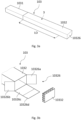
- an installation kit 100 according to the invention is shown in a partly packed condition.
- the installation kit 100 is intended for use in the installation of a roof window system 1 as shown in Fig. 5 , with two window units 11, 12 to be installed side-by-side in an inclined roof structure 2 using the components of installation assemblies and auxiliary equipment of the packed installation kit 100 according to the innovation.
- the roof structure comprises 2 a number of rafters and battens of which two rafters 21 on either side of the window units 11, 12 and one batten 22 are indicated.
- the roof structure 2 may include further and/or alternative parts.
- the installation kit 1 here comprises a second set of installation assemblies 3, which is a support assembly 3 which has an upper support beam 31 and a lower support beam 32.
- the two support beams 31, 32 have identical lengths L3, identical heights H3 and identical widths, the sum of their widths being the common width B3.
- the support beams 31, 32 are shown side-by-side extending along the lengths of one another.
- a second packaging 103 is shown to accommodate the support beams 31, 32.
- the second packaging 103 comprises a rectangular telescopic tube packaging which has two parts, a first part 1031 and a second part 1032, both of which are made of corrugated cardboard.
- the first part 1031 has first length L1, width B1 and height H1.
- the second part 1032 has a second length L2, a width B2 and a height H2.
- the sum of the first length L1 and the second length L2 exceeds the length L3 of the support beams 31, 32.
- the sum of the lengths L1 and L2, is denoted the total length of the second packaging.
- the first length L1 in Fig. 1 may for example be about 1500 mm while the second length L2 may be about 1200 mm and the length L3 may be about 1700 mm.
- the material thickness of the cardboard is about 3 mm, but could vary slightly.
- the first part 1031 has an opening 10310 at one longitudinal end of the first part 1031, and the opening 10310 has suitable dimensions for accommodating the two support beams 31, 32 lengthwise.
- An end portion 10316 of the first part 1031 is located opposite to the opening 10310.
- the end portion 10316 closes off the first part 1031.
- the second part 1032 has an opening 10320 and an end portion 10326, which is seen to close off one longitudinal end of the of the second part 1032.
- the end portions 10316, 10326 may in some orientations of the packed installation kit, carry the load of the support beams 31, 32.
- the end portions 10316, 10326 may suitably be reinforced, with several layers of cardboard material, preferably corrugated cardboard, by an additional element such as a honeycomb element and/or by providing an additional folding flap.
- the support beams 31, 32 are provided with such dimensions and selected from such a material that they are able to provide sufficient strength and withstand wear typical of the conditions within a roof structure.
- a wooden material is chosen and may include laminated wooden beams such as Glulam beams, Kerto ® beams etc., which are dimensionally stable, strong and light-weight. While the support beams 31, 32 are light-weight in comparison to materials such as steel, the dimensions alone render them cumbersome to handle and pack.
- the support beams 31, 32 extend between rafters 21 on either side of the first and second window units 11, 12.
- Fig. 2 which shows the installation kit of Fig. 1 during packing of the support beams 31, 32 of the support assembly 3 in the second packaging 103.
- the support beams 31, 32 are accommodated side-by-side in the first part 1031 of the second packaging 103.
- the support beams 31, 32 are enclosed to a large extent in the first part 1031, but a portion thereof protrudes from the opening 10310.
- about 85 % of the support beams 31, 32 are accommodated in the first part 1031.
- the protruding portion of the support assembly 3, is seen to be shorter than the second length L2 of the second part 1032.
- the height H1 and width B1 of the first part 1031 is selected such that, when accounting for the thickness of the corrugated cardboard, a snug fit between the support assembly 3 and the interior surfaces of first part 1031 is provided.
- the snug fit between the first part 1031 and the support assembly is preferably snug such that the support assembly 3 does not inadvertently slide in the first part 1031, during handling, but not so snug that it impedes unpacking of the of packed installation kit 1.
- Fig. 3a in which the second part 1032 of the second packaging 103 has been slid on to the support assembly 3 and the first part 1031 of the second packaging in a telescoping manner, to provide a supply condition of the installation kit.
- the second part 1032 constitutes an outer part of the second packaging 103, and an overlap LO is provided between the first 1031 and second part 1032.
- the length LO of the overlap in this embodiment substantially amounts to the difference between the length L3 and the sum of first L1 and second length L2.
- the first 1031 and second part 1032 having lengths L1 and L2 as shown in Figs 1 to 3 would provide an overlap LO in the supply condition for a predefined range of lengths L3 of the support beams 31, 32.
- the predefined range for the length L3 has an upper limit of less than the sum of the first L1 and second length L2, although a suitable overlap may in practice require the length L3 to be less than e.g. 95% of the length of sum of the first L1 and second length L2.
- the length L3 is about 65 % of the sum of the first L1 and second length L2.
- the length L3 will typically vary between about 1000 mm and up to 3000 mm.
- the first part 1031 may have the same length L1, here 1500 mm, throughout the full range, while the length L2 of the second part 1032 may be provided in two different sizes, one of 1200 mm to cover the lower sub-range and one of 1500 mm to cover the upper sub-range.
- the height H2 and width B2 of the second part 1032 are selected to be greater than the corresponding height H1 and width B1 of the first part 1031, such that, accounting for the corrugated cardboard thickness of the second part, the second part 1032 can be slid on to the first part 1031 in the telescopic manner.
- the height H2 and width B2 is preferably further selected such that a snug fit between the interior surfaces of the second part 1032 and the exterior surfaces of the first part 1031 is provided. In this way the first and second parts of the second packaging is kept together in the supply condition.
- the length L1 of the of the first part 1031 is identical for lengths L3 within a pre-defined range, while the length L2 of the second part is selected according in accordance with the length L3, optionally from a few pre-defined lengths L2, such as two pre-defined lengths L2.
- the first length L1 is longer than the second length L2, which slightly improves the carbon footprint of the second packaging, as the first part 1031, has a smaller height H1 and width B1, than the second part 1032, thus reducing the amount of material used in the packaging.
- the first part 1031 and the second part 1032 may further have fixating means for positioning the first part 1031 relative to the support beams 31, 32 and for positioning the second part 1032 relative to the support beams 31, 32 and/or the first part 1031.
- fixating means in the forms of clamps or staples 10330 are shown.
- a tape strip 10331 may be provided.
- Fig. 3b shows a view of an embodiment of the second packaging 103, in which means are provided to reinforce the end portion 10326.
- the reinforcement means comprise, non-exhaustively, provision of a plurality of cardboard layers at the end portion, provision of a shock-absorbing element at the end portion, and provision of an extended flap portion configured to overlap an exterior side of the second packaging.
- the reinforcement means comprise positioning a shock-absorbing element in the form of a honeycomb element 10332 between ends of the support beams 31, 32 (not visible) and the end portion 10326 of the second packaging 103.
- a counterpart honeycomb element 10332 may be provided at the other end portion 10316.
- Further reinforcement means comprise the provision of several cardboard layers, in the embodiment shown in Fig. 3b in the form of three end flaps 10326a, 10326b, 10326c that in themselves provide reinforcement. Here, they are supplemented by an extended flap portion 10326d configured to overlap an exterior side of the second packaging 103 once the end portion 10326 has been closed.
- the other end portion 10316 may be configured in a similar way. There may also be differences between the end portions 10316, 10326, for instance in case one end is designated to be a bottom end during storage.
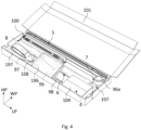
- Fig. 4 shows part of another embodiment of a packed installation kit 100 according to the invention.
- the packed installation kit 100 can in some embodiments further comprise a first set of installation assemblies 4, 5, 6, 7, 8 packed in a first packaging 101.
- Fig. 4 shows a set of first installation assemblies packed and accommodated in the first packaging 101, which first packaging further accommodates auxiliary equipment 96, 96a, 97, 98.
- a first installation assembly which is here an insulating assembly 5
- a second installation assembly which is here a stabilizing assembly 6
- a third installation assembly which is here a support assembly 4 including four mounting brackets
- a fourth installation assembly which is here a cover assembly comprising receiver brackets 7
- a fifth installation assembly which is here a cover plate 8.
- the packed installation kit 100 is in Fig. 4 shown in a condition where the first packaging 101 is open, allowing the components accommodated therein to be seen.
- the first packaging 101 When the packed installation kit is shipped and supplied the first packaging 101 will be closed, providing the installation kit in a supply condition.
- the first packaging 101 When the first packaging 101 is closed it will be a box shaped as rectangular prism of corrugated cardboard with a length extending in the longitudinal direction LP, a width in the width direction WP and a height in the height direction HP.
- the first packaging 101 is made of corrugated cardboard, which is sometimes called corrugated fibreboard.
- the insulating assembly 5 is accommodated in the first packaging 101 as is, that is the components of the assembly are not packed in a sub-packaging nor is it fixated to the first packaging 110, whereas the mounting brackets 4, receiver brackets 7 and cover plate 8 are packed in sub-packaging of cardboard or paper material, namely cardboard box 104, cardboard box 107 and paper wrapping 108 respectively.
- the first packaging 101 further accommodates auxiliary equipment, namely underroof collar 96 packed in a plastic bag 196, tape roll 96a, a vapour barrier collar 97 packed in a plastic bag 197, a gutter element 98 and an installation manual (not shown).
- the plastic bags 196, 197 are intended for collection of waste, in particular plastic waste, during unpacking of the installation kit and installation the skylight window system 1. Further details of the first packaging and the first set of installation assemblies may be found in Applicant's co-pending European patent application filed on the same day as the present application.
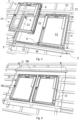
- the roof window system 1 is shown from the exterior of the building and in Fig. 5 the first window unit 11 is mounted in the roof structure 2 and the second window unit 12 is being mounted next to the first window unit 11. In the mounted condition, the roof window system 1 has a combined width W and a common height H, both of which are seen to extend in parallel with the plane of the roof structure 2.
- the roof window system 1 is being installed using a support assembly 3, mounting brackets 4, an insulating assembly 5 and a stabilizing assembly 6.
- the upper support beam 31 and lower support beam 32 of the support assembly 3 are installed in the roof structure 2 and the roof window system 1 is fastened to them.
- the length L3 of the two support beams 31, 32 corresponds substantially to the combined width W of the roof window system 1.
- the insulating frame assembly 5 is a frame surrounding the roof window system 1 in the mounted position and the length of the side members of the frame slightly exceeds the common height H of the roof window system 1.
- both window units 11, 12 of the roof window system 1 are mounted in the roof structure 2 and auxiliary equipment is being installed.
- the auxiliary equipment is here an underroof collar 96 which is mounted around the roof window system 1 and a gutter element 98.
- Figs 7 and 8 show views of the roof window system 1 of Fig.
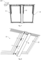
- Fig. 7 shows the roof window system when the vapour barrier collar 97 is installed after having been unpacked from its sub-packaging 197 which is here a plastic bag.
- Fig. 8 shows receiver brackets 7 being installed to receive and mount the cover plate 8.
- the first packaging 101 may be closed and sealed by suitable means including adhesive, tape strips, clamps and/or staples. Closure and sealing of the second packaging 103 is carried out as described in the above. Opening of the packagings 101, 103 is typically carried out by tearing or cutting at suitable positions to expose the contents. It is also conceivable to include opening means in the form of tear strips to provide facilitated opening. If so, it is preferred that the tear strips are of the perforated type, i.e. not involving a thread or wire of plastic or metal material.
- first part 1031 and the second part 1032 of the packaging 103 may be provided in the form presented in Figs 1 to 3b , i.e. folded to form a respective tubular shape, it is also conceivable to use a cardboard blank as a substrate during handling of the support assembly comprising the two support beams 31, 32, following which the cardboard material is folded and closed, thus wrapping the support beams 31, 32.
- FIG. 9 is a plan view of the blank.
- the blank is a sheet of corrugated cardboard which is provided with folding lines and cuts which define portions of the blank.
- At one longitudinal end of the blank there is four end flaps 10316a, 10316b, 10316c, 10316d, which in the folded condition form sections of the end portion 10316 of the first part.
- the end flaps 10316a, 10316b, 10316c, 10316d overlap to close off the end portion 10316 of the first part 1031.
- the end portion 10316 will be reinforced as it will be formed of four layers of corrugated cardboard.
- the end flaps 10316a, 10316b, 10316c, 10316d may be fixated to each other by adhesive or glue between some or all the end flaps. In the embodiment shown, there are no flaps at the opposite end of the blank, and hence the first part 1031 folded from the blank will be open at that end, providing the opening 10310.
- Four folding lines extend longitudinally across the blank, segmenting the blank into a top portion 10311, side portion 10313, base portion 10314, further side portion 10312 and flap portion 10315.
- the side portions 10312, 10313 have identical widths and the top 10311 and base portions 10314 have identical widths, whereby the first part 1031 in the folded state will have rectangular cross-section.
- the flap portion 10315 will overlap partly with the exterior surface of the top portion 10311, providing overlapping surfaces which may be fixated to each other e.g. by means of an adhesive or glue, or by means of clamps or staples.
- the amount of adhesive or glue used in the first packaging 101 and the second packaging 103 is preferably comparatively low, e.g. the mass of adhesive or glue is low compared to the mass of packaging, such as less than 2 %, less than 1.5 %, less than 1 %, less than 0.5 % or even less than 0.1 % by weight of the packaging.
- the folding lines can comprise a weakening of the corrugated cardboard materials, such as perforations, cuts or the cardboard material having been compressed at the folding line.
- the blank of the first part 1031 can be folded to form the first part 1031 prior to inserting the components 1031, 1032 of the support assembly 3 therein.
- the components 1031, 1032 can be placed on the blank of the first part 1031 whereupon the blank is folded around the components to form the first part 1031 as shown in Fig. 10 .
- the components of the support assembly 3 are placed side-by-side on the base portion 10314 of the blank of the first part 1031, and subsequently the blank can be folded around the components to form the first part 1031 of the second packaging 103.
- Figs 9 and 10 only show a blank to constitute a first blank to form the first part 1031 of the second packaging 103, it is understood that a similar, second blank can be provided for the second part 1032.
- Such a second blank to form the second part 1032 may be folded around the components of the support assembly 3 which are accommodated in the first part, similarly to the process of Fig. 10 , to provide the supply condition of the packed installation kit 100.
- the packaging to be formed is able accommodate the full length of the components of the support assembly 3.
- the means for reinforcing the end portions are applicable.
- a plurality of end flaps including two, three or four end flaps may be provided at either end of the blank.
- the use of an overlapping flap portion, corresponding to the flap portion 10315, to cover the full length of such a packaging is conceivable.
- Fixating means in the forms of clamps or staples may be applied throughout the length of the packaging, partly to strengthen the coherence of the packaging itself, partly to provide additional retention of the components of the second set of installation assemblies in the length direction of the packaging, thus mitigating the effect of possible pressure or impact acting on the end portions in case the support beams move in the longitudinal direction of the second packaging.
Landscapes
- Engineering & Computer Science (AREA)
- Mechanical Engineering (AREA)
- Packaging Of Machine Parts And Wound Products (AREA)
- Buffer Packaging (AREA)
- Packaging Of Annular Or Rod-Shaped Articles, Wearing Apparel, Cassettes, Or The Like (AREA)
Claims (15)
- Verpacktes Installationskit (100) zur Verwendung bei der Installation eines Dachfenstersystems, umfassend zwei Fenstereinheiten (11, 12) und dazu konfiguriert, nebeneinander in einer geneigten Dachstruktur (2) eingebaut zu werden, so dass das Dachfenstersystem im montierten Zustand eine gemeinsame Höhe (H) und eine kombinierte Breite (W) definiert, wobei das Installationskit (100) eine Anzahl von Installationsbaugruppen (3, 4, 5, 6, 7, 8), die jeweils eine oder mehrere Komponenten aufweisen, und optional Zusatzausrüstung (96, 96A, 97, 98) umfasst.
dadurch gekennzeichnet, dassdie Komponenten eines ersten Satzes von Installationsbaugruppen (4, 5, 6, 7, 8) des Installationskits (100) in einer ersten Verpackung (101) aufgenommen sind, dassdie Komponenten eines zweiten Satzes von Installationsbaugruppen (3) des Installationskits (100) zwei Stützbalken (31, 32) umfassen, die nebeneinander in einer zweiten Verpackung (103), die eine rechteckige Teleskoprohrverpackung mit zwei Teilen (1031, 1032) aus Wellpappe umfasst, aufgenommen sind, wobei ein erster Teil (1031) der zweiten Verpackung (103) eine erste Länge (L1) aufweist, die sich zwischen einem Endabschnitt (10316) und einer Öffnung (10310) erstreckt, und ein zweiter Teil (1032) eine zweite Länge (L2) aufweist, die sich zwischen einem Endabschnitt (10326) und einer Öffnung (10320) erstreckt, und die Stützbalken (31, 32) eine Länge (L3) innerhalb eines vordefinierten Bereichs aufweisen, dassdie Gesamtlänge der zweiten Verpackung (103), wie durch die Summe der Länge (L1) des ersten Teils (1031) und der Länge (L2) des zweiten Teils (1032) definiert, die Länge (L3) der Stützbalken (31, 32) überschreitet, so dass eine Überlappung (LO) zwischen dem zweiten Teil (1032) und dem ersten Teil (1031) in einem Lieferzustand des Installationskits (100) innerhalb des vordefinierten Bereichs von Längen der Stützbalken (31, 32) des zweiten Satzes von Installationsbaugruppen (3) bereitgestellt ist, und dassMittel bereitgestellt sind, um mindestens einen von den Endabschnitten (10316, 10326) zu verstärken, wobei die Verstärkungsmittel aus der Gruppe ausgewählt sind, die umfasst:- Bereitstellung einer Vielzahl von Wellpappeschichten am Endabschnitt,- Bereitstellung eines stoßabsorbierenden Elements am Endabschnitt, und- Bereitstellung eines erweiterten Laschenabschnitts, der dazu konfiguriert ist, eine Außenseite der zweiten Verpackung (103) zu überlappen. - Verpacktes Installationskit (100) nach Anspruch 1, wobei der erste Teil (1031) der zweiten Verpackung (103) im Lieferzustand eine inneres Teil bildet, wobei der erste Teil (1031) eine solche Breite (B1) und Höhe (H1) für eine bestimmte Materialdicke der Wellpappe aufweist, dass eine gute Passung zwischen dem Inneren des ersten Teils (1031) der zweiten Verpackung (103) und den zwei nebeneinander aufgenommenen Stützbalken (31, 32) der Stützbaugruppe (3) hergestellt wird, wobei die zwei Stützbalken (31, 32) der Stützbaugruppe (3) vorzugsweise identische Höhen (H3) und eine Gesamtbreite (B3), die das Doppelte jedes Stützbalkens (31, 32) beträgt, aufweisen.
- Verpacktes Installationskit (100) nach Anspruch 2, wobei der zweite Teil (1032) der zweiten Verpackung (103) im Lieferzustand einen äußeren Teil bildet, wobei der zweite Teil (1032) für eine gegebene Materialdicke der Wellpappe eine solche Breite (B2) und Höhe (H2) aufweist, dass eine gute Passung zwischen dem Inneren des zweiten Teils (1032) und dem Äußeren des ersten Teils (1031) bereitgestellt ist.
- Verpacktes Installationskit (100) nach einem der vorhergehenden Ansprüche, wobei die Länge (L1) des ersten Teils (1031) der zweiten Verpackung (103) länger als die oder gleich der Länge (L2) des zweiten Teils (1032) der zweiten Verpackung (103) ist.
- Verpacktes Installationskit (100) nach einem der vorhergehenden Ansprüche, wobei die Länge (L1) des ersten Teils (1031) der zweiten Verpackung (103) für verschiedene Längen (L3) der Stützbalken (31, 32) innerhalb des vordefinierten Bereichs identisch ist, wobei die Länge (L1) des ersten Teils (1031) der zweiten Verpackung (103) vorzugsweise 1400 bis 1600 mm, stärker bevorzugt etwa 1500 mm, ist.
- Verpacktes Installationskit (100) nach Anspruch 5, wobei die Länge (L2) des zweiten Teils (1031) der zweiten Verpackung (103) entsprechend der Länge (L3) der Stützbalken (31, 32) ausgewählt ist, vorzugsweise so, dass für einen entsprechenden Teilbereich innerhalb des vordefinierten Bereichs eine Länge ausgewählt ist, wobei die Länge (L2) des zweiten Teils (1032) der zweiten Verpackung (103) in einem kürzeren Teilbereich vorzugsweise 1000 bis 1400 mm, stärker bevorzugt etwa 1200 mm, beträgt, und wobei die Länge (L2) des zweiten Teils (1032) der zweiten Verpackung (103) in einem längeren Teilbereich vorzugsweise 1400 bis 1600 mm, stärker bevorzugt etwa 1500 mm, beträgt.
- Verpacktes Installationskit (100) nach einem der vorhergehenden Ansprüche, wobei Befestigungsmittel (10330) bereitgestellt sind, um zumindest den ersten Teil (1031) der zweiten Verpackung (103) relativ zu den zwei Stützbalken (31, 32) der Stützbaugruppe (3) zu positionieren, vorzugsweise auch Befestigungsmittel zum Positionieren des zweiten Teils (1032) der zweiten Verpackung (103) relativ zum ersten Teil (1031) und/oder zu den zwei Stützbalken (31, 32).
- Verpacktes Installationskit (100) nach einem der vorhergehenden Ansprüche, wobei die Verstärkungsmittel das Positionieren eines stoßabsorbierenden Elements umfassen, das mindestens ein Wabenelement (10332) zwischen Enden der Stützbalken (31, 32) und dem Endabschnitt (10326, 10316) der zweiten Verpackung (103) umfasst, wobei vorzugsweise an jedem Endabschnitt (10326, 10316) ein Wabenelement (10332) bereitgestellt ist.
- Verpacktes Installationskit nach einem der vorhergehenden Ansprüche, wobei die Verstärkungsmittel das Bereitstellen einer Vielzahl von Wellpappeschichten in der Form von zwei, drei oder vier Abschlusslaschen (10316a, 10316b, 10316c, 10316c; 10326a, 10326b, 10326c), optional kombiniert mit einem erweiterten Laschenabschnitt (10326d), der dazu konfiguriert ist, eine Außenseite der zweiten Verpackung zu überlappen, umfassen.
- Verpacktes Installationskit nach einem der vorhergehenden Ansprüche, wobei die erste Verpackung (101) eine Kiste umfasst, die als ein rechteckiges Prisma geformt ist, vorzugsweise aus Wellpappe, mit einer Länge in einer Längsrichtung (LP), einer Breite in einer Breitenrichtung (WP) und einer Höhe in einer Höhenrichtung (HP), um den Lieferzustand des Installationskits bereitzustellen, und wobei die Komponenten des ersten Satzes von Installationsbaugruppen (4, 5, 6, 7, 8) des Installationskits (100) in der ersten Verpackung (101) entweder in ihrer ursprünglichen Form oder teilweise oder vollständig verpackt in einer Unterverpackung (104, 1063, 1064, 107, 108) aus Karton- oder Papiermaterial aufgenommen sind.
- Verfahren zum Ausbilden eines verpackten Installationskits nach Anspruch 1, umfassend die Schritte:Bereitstellen mindestens eines Zuschnitts, der solche Abmessungen aufweist, dass er in einem gefalteten Zustand die zweite Verpackung (103) ausbilden kann,Bereitstellen von Verstärkungsmitteln,Platzieren der Komponenten in der zweiten Verpackung, undAnwenden der Verstärkungsmittel, um einen Lieferzustand des verpackten Installationskits bereitzustellen.
- Verfahren nach Anspruch 11,
umfassend die Schritte:Bereitstellen von zwei Zuschnitten, die in einem gefalteten Zustand den ersten Teil (1031) beziehungsweise den zweiten Teil (1032) der zweiten Verpackung (103) ausbilden,Platzieren der Komponenten im ersten Teil (1031),Überlappen des zweiten Teils (1032) mit dem ersten Teil (1031), um einen Lieferzustand des verpackten Installationskits bereitzustellen. - Verfahren nach Anspruch 11 oder 12, wobei die Komponenten auf dem mindestens einen Zuschnitt platziert werden, bevor mindestens einige der Faltvorgänge ausgeführt werden.
- Verfahren nach den Ansprüchen 12 und 13, wobei die Komponenten (31, 32) auf dem ersten Zuschnitt platziert werden, der im gefalteten Zustand den ersten Teil (1031) ausbildet, bevor die Faltung ausgeführt wird, wonach die Komponenten, die mindestens teilweise vom ersten Teil (1031) umschlossen sind, entweder auf dem zweiten Zuschnitt, der im gefalteten Zustand den zweiten Teil (1032) ausbildet, positioniert werden, bevor die Faltung ausgeführt wird, oder der zweite Zuschnitt zu dem zweiten Teil (1032) ausgebildet wird, bevor der zweite Teil (1032) mit dem ersten Teil (1031) und den Komponenten verbunden wird.
- Verfahren nach einem der Ansprüche 11 bis 14, wobei der Schritt des Bereitstellens von Verstärkungsmitteln einen oder mehrere der folgenden Vorgänge umfasst:- Bereitstellen des mindestens einen Zuschnitts mit einer Vielzahl von Wellpappeschichten,- Bereitstellen mindestens eines stoßabsorbierenden Elements,- Bereitstellen mindestens eines Zuschnitts mit einem erweiterten Laschenabschnitt an einem oder beiden Längsenden des Zuschnitts.
Applications Claiming Priority (1)
| Application Number | Priority Date | Filing Date | Title |
|---|---|---|---|
| DKPA202170243 | 2021-05-12 |
Publications (4)
| Publication Number | Publication Date |
|---|---|
| EP4089031A2 EP4089031A2 (de) | 2022-11-16 |
| EP4089031A3 EP4089031A3 (de) | 2022-12-07 |
| EP4089031C0 EP4089031C0 (de) | 2024-01-24 |
| EP4089031B1 true EP4089031B1 (de) | 2024-01-24 |
Family
ID=81648807
Family Applications (1)
| Application Number | Title | Priority Date | Filing Date |
|---|---|---|---|
| EP22172945.2A Active EP4089031B1 (de) | 2021-05-12 | 2022-05-12 | Verpacktes installationskit, das eine installationsanordnung mit stützbalken als komponenten umfasst |
Country Status (3)
| Country | Link |
|---|---|
| EP (1) | EP4089031B1 (de) |
| HU (1) | HUE065533T2 (de) |
| PL (1) | PL4089031T3 (de) |
Family Cites Families (4)
| Publication number | Priority date | Publication date | Assignee | Title |
|---|---|---|---|---|
| DE1906464U (de) * | 1964-10-06 | 1964-12-10 | Europa Carton Ag | Verpackungspolster. |
| DK200500501A (da) * | 2005-04-08 | 2006-10-09 | Vkr Holding As | Fremgangsmåde, holdelegeme og emballage til emballering af et produkt omfattende en flerhed af delkomponenter |
| EP2778086B1 (de) * | 2013-03-11 | 2017-04-19 | Sanofi-Aventis Deutschland GmbH | Verpackungsanordnung für mindestens zwei Elemente |
| ITUB20160095A1 (it) * | 2016-02-03 | 2017-08-03 | Arti Grafiche Reggiane & Lai S P A | Scatola con dispositivo di illuminazione |
-
2022
- 2022-05-12 EP EP22172945.2A patent/EP4089031B1/de active Active
- 2022-05-12 PL PL22172945.2T patent/PL4089031T3/pl unknown
- 2022-05-12 HU HUE22172945A patent/HUE065533T2/hu unknown
Also Published As
| Publication number | Publication date |
|---|---|
| EP4089031C0 (de) | 2024-01-24 |
| EP4089031A2 (de) | 2022-11-16 |
| HUE065533T2 (hu) | 2024-05-28 |
| EP4089031A3 (de) | 2022-12-07 |
| PL4089031T3 (pl) | 2024-06-24 |
Similar Documents
| Publication | Publication Date | Title |
|---|---|---|
| US20140238879A1 (en) | Packaging for a window and a method for packing | |
| EP4089025B1 (de) | Verpacktes dachfenster | |
| US5531166A (en) | Corrugated fiberboard riser | |
| US20020033351A1 (en) | Packaging box and method packaging | |
| EP4089031B1 (de) | Verpacktes installationskit, das eine installationsanordnung mit stützbalken als komponenten umfasst | |
| EP4089034B1 (de) | Verpacktes installationskit mit installationsanordnungen für ein dachfenstersystem | |
| CZ37862U1 (cs) | Obal pro montážní sadu obsahující montážní sestavy pro systém střešních oken | |
| EP4412922B1 (de) | Verpacktes dachfensterprodukt, verfahren zum verpacken eines verpackten dachfensterprodukts und verfahren zum entpacken eines verpackten dachfensterprodukts | |
| CZ37830U1 (cs) | Sestava lepenkové krabice obsahující lepenkovou krabici a v ní střešní okno a obalové komponenty pro ochranu a uchycení komponent střešního okna | |
| US8141708B2 (en) | Container for glass products | |
| WO2008008272A9 (en) | Container for glass products | |
| EP1671895A2 (de) | Transporteinheit für Steinwollprodukte, insbesondere gestapelte Steinwollplatten | |
| EP4269262A1 (de) | Behälter für wiederholte verwendungen | |
| EP3590867A1 (de) | Verfahren zum verpacken eines vormontierten produkts zur verwendung an einem dach in einer verpackungseinheit und verpackungseinheit mit einer ersten und einer zweiten verpackung | |
| DK181780B1 (en) | A packed kit of flashing and/or covering members for a roof window and a method for packing a kit of flashing and/or covering members | |
| WO2010096536A2 (en) | Carton and carton blank corner structure | |
| US20210122507A1 (en) | Paper Banding For Corrugated Paperboard | |
| EP4368530A1 (de) | Verfahren zum verpacken eines dachfensters und verpacktes dachfenster | |
| EP1591368B1 (de) | Verpackungs- und/oder Transporteinheit für plattenförmige Dämmstoffelemente, Transportgebinde und Verfahren zur Herstellung einer Verpackungs- und/oder Transporteinheit für plattenförmige Dämmstoffelemente | |
| DK181313B1 (en) | Packed roof window products | |
| US20260048894A1 (en) | Blank configured to be erected into a package and a package formed by such a blank | |
| EP4303144A1 (de) | Verpackungsschachtel aus naturfaserplatte | |
| EP4212446A1 (de) | Halteelement zur verwendung beim verpacken eines produkts, verpackung, verfahren zur herstellung eines halteelements und verfahren zum verpacken eines produkts | |
| FI12316U1 (fi) | Kierrätyskontin aihio ja kierrätyskontti | |
| EP4446246A1 (de) | Zuschnitt zum falten in eine schutzstruktur, aus solch einem zuschnitt geformte schutzstruktur und verpackung mit solch einer schutzstruktur |
Legal Events
| Date | Code | Title | Description |
|---|---|---|---|
| PUAI | Public reference made under article 153(3) epc to a published international application that has entered the european phase |
Free format text: ORIGINAL CODE: 0009012 |
|
| STAA | Information on the status of an ep patent application or granted ep patent |
Free format text: STATUS: THE APPLICATION HAS BEEN PUBLISHED |
|
| PUAL | Search report despatched |
Free format text: ORIGINAL CODE: 0009013 |
|
| AK | Designated contracting states |
Kind code of ref document: A2 Designated state(s): AL AT BE BG CH CY CZ DE DK EE ES FI FR GB GR HR HU IE IS IT LI LT LU LV MC MK MT NL NO PL PT RO RS SE SI SK SM TR |
|
| AK | Designated contracting states |
Kind code of ref document: A3 Designated state(s): AL AT BE BG CH CY CZ DE DK EE ES FI FR GB GR HR HU IE IS IT LI LT LU LV MC MK MT NL NO PL PT RO RS SE SI SK SM TR |
|
| RIC1 | Information provided on ipc code assigned before grant |
Ipc: B65D 5/02 20060101ALI20221028BHEP Ipc: B65D 81/127 20060101ALI20221028BHEP Ipc: B65D 81/107 20060101ALI20221028BHEP Ipc: B65D 5/68 20060101ALI20221028BHEP Ipc: B65D 5/50 20060101ALI20221028BHEP Ipc: B65D 85/64 20060101ALI20221028BHEP Ipc: B65D 77/04 20060101AFI20221028BHEP |
|
| STAA | Information on the status of an ep patent application or granted ep patent |
Free format text: STATUS: REQUEST FOR EXAMINATION WAS MADE |
|
| 17P | Request for examination filed |
Effective date: 20230531 |
|
| RBV | Designated contracting states (corrected) |
Designated state(s): AL AT BE BG CH CY CZ DE DK EE ES FI FR GB GR HR HU IE IS IT LI LT LU LV MC MK MT NL NO PL PT RO RS SE SI SK SM TR |
|
| GRAP | Despatch of communication of intention to grant a patent |
Free format text: ORIGINAL CODE: EPIDOSNIGR1 |
|
| STAA | Information on the status of an ep patent application or granted ep patent |
Free format text: STATUS: GRANT OF PATENT IS INTENDED |
|
| INTG | Intention to grant announced |
Effective date: 20231031 |
|
| GRAS | Grant fee paid |
Free format text: ORIGINAL CODE: EPIDOSNIGR3 |
|
| GRAA | (expected) grant |
Free format text: ORIGINAL CODE: 0009210 |
|
| STAA | Information on the status of an ep patent application or granted ep patent |
Free format text: STATUS: THE PATENT HAS BEEN GRANTED |
|
| AK | Designated contracting states |
Kind code of ref document: B1 Designated state(s): AL AT BE BG CH CY CZ DE DK EE ES FI FR GB GR HR HU IE IS IT LI LT LU LV MC MK MT NL NO PL PT RO RS SE SI SK SM TR |
|
| REG | Reference to a national code |
Ref country code: GB Ref legal event code: FG4D |
|
| REG | Reference to a national code |
Ref country code: CH Ref legal event code: EP |
|
| REG | Reference to a national code |
Ref country code: IE Ref legal event code: FG4D |
|
| REG | Reference to a national code |
Ref country code: DE Ref legal event code: R096 Ref document number: 602022001662 Country of ref document: DE |
|
| U01 | Request for unitary effect filed |
Effective date: 20240209 |
|
| U07 | Unitary effect registered |
Designated state(s): AT BE BG DE DK EE FI FR IT LT LU LV MT NL PT SE SI Effective date: 20240220 |
|
| U20 | Renewal fee for the european patent with unitary effect paid |
Year of fee payment: 3 Effective date: 20240408 |
|
| REG | Reference to a national code |
Ref country code: HU Ref legal event code: AG4A Ref document number: E065533 Country of ref document: HU |
|
| PG25 | Lapsed in a contracting state [announced via postgrant information from national office to epo] |
Ref country code: IS Free format text: LAPSE BECAUSE OF FAILURE TO SUBMIT A TRANSLATION OF THE DESCRIPTION OR TO PAY THE FEE WITHIN THE PRESCRIBED TIME-LIMIT Effective date: 20240524 |
|
| PG25 | Lapsed in a contracting state [announced via postgrant information from national office to epo] |
Ref country code: GR Free format text: LAPSE BECAUSE OF FAILURE TO SUBMIT A TRANSLATION OF THE DESCRIPTION OR TO PAY THE FEE WITHIN THE PRESCRIBED TIME-LIMIT Effective date: 20240425 |
|
| PG25 | Lapsed in a contracting state [announced via postgrant information from national office to epo] |
Ref country code: RS Free format text: LAPSE BECAUSE OF FAILURE TO SUBMIT A TRANSLATION OF THE DESCRIPTION OR TO PAY THE FEE WITHIN THE PRESCRIBED TIME-LIMIT Effective date: 20240424 Ref country code: HR Free format text: LAPSE BECAUSE OF FAILURE TO SUBMIT A TRANSLATION OF THE DESCRIPTION OR TO PAY THE FEE WITHIN THE PRESCRIBED TIME-LIMIT Effective date: 20240124 |
|
| PG25 | Lapsed in a contracting state [announced via postgrant information from national office to epo] |
Ref country code: ES Free format text: LAPSE BECAUSE OF FAILURE TO SUBMIT A TRANSLATION OF THE DESCRIPTION OR TO PAY THE FEE WITHIN THE PRESCRIBED TIME-LIMIT Effective date: 20240124 |
|
| PG25 | Lapsed in a contracting state [announced via postgrant information from national office to epo] |
Ref country code: RS Free format text: LAPSE BECAUSE OF FAILURE TO SUBMIT A TRANSLATION OF THE DESCRIPTION OR TO PAY THE FEE WITHIN THE PRESCRIBED TIME-LIMIT Effective date: 20240424 Ref country code: NO Free format text: LAPSE BECAUSE OF FAILURE TO SUBMIT A TRANSLATION OF THE DESCRIPTION OR TO PAY THE FEE WITHIN THE PRESCRIBED TIME-LIMIT Effective date: 20240424 Ref country code: IS Free format text: LAPSE BECAUSE OF FAILURE TO SUBMIT A TRANSLATION OF THE DESCRIPTION OR TO PAY THE FEE WITHIN THE PRESCRIBED TIME-LIMIT Effective date: 20240524 Ref country code: HR Free format text: LAPSE BECAUSE OF FAILURE TO SUBMIT A TRANSLATION OF THE DESCRIPTION OR TO PAY THE FEE WITHIN THE PRESCRIBED TIME-LIMIT Effective date: 20240124 Ref country code: GR Free format text: LAPSE BECAUSE OF FAILURE TO SUBMIT A TRANSLATION OF THE DESCRIPTION OR TO PAY THE FEE WITHIN THE PRESCRIBED TIME-LIMIT Effective date: 20240425 Ref country code: ES Free format text: LAPSE BECAUSE OF FAILURE TO SUBMIT A TRANSLATION OF THE DESCRIPTION OR TO PAY THE FEE WITHIN THE PRESCRIBED TIME-LIMIT Effective date: 20240124 |
|
| PG25 | Lapsed in a contracting state [announced via postgrant information from national office to epo] |
Ref country code: SM Free format text: LAPSE BECAUSE OF FAILURE TO SUBMIT A TRANSLATION OF THE DESCRIPTION OR TO PAY THE FEE WITHIN THE PRESCRIBED TIME-LIMIT Effective date: 20240124 |
|
| REG | Reference to a national code |
Ref country code: DE Ref legal event code: R097 Ref document number: 602022001662 Country of ref document: DE |
|
| PG25 | Lapsed in a contracting state [announced via postgrant information from national office to epo] |
Ref country code: SK Free format text: LAPSE BECAUSE OF FAILURE TO SUBMIT A TRANSLATION OF THE DESCRIPTION OR TO PAY THE FEE WITHIN THE PRESCRIBED TIME-LIMIT Effective date: 20240124 |
|
| PG25 | Lapsed in a contracting state [announced via postgrant information from national office to epo] |
Ref country code: SM Free format text: LAPSE BECAUSE OF FAILURE TO SUBMIT A TRANSLATION OF THE DESCRIPTION OR TO PAY THE FEE WITHIN THE PRESCRIBED TIME-LIMIT Effective date: 20240124 Ref country code: SK Free format text: LAPSE BECAUSE OF FAILURE TO SUBMIT A TRANSLATION OF THE DESCRIPTION OR TO PAY THE FEE WITHIN THE PRESCRIBED TIME-LIMIT Effective date: 20240124 |
|
| PLBE | No opposition filed within time limit |
Free format text: ORIGINAL CODE: 0009261 |
|
| STAA | Information on the status of an ep patent application or granted ep patent |
Free format text: STATUS: NO OPPOSITION FILED WITHIN TIME LIMIT |
|
| 26N | No opposition filed |
Effective date: 20241025 |
|
| PG25 | Lapsed in a contracting state [announced via postgrant information from national office to epo] |
Ref country code: MC Free format text: LAPSE BECAUSE OF FAILURE TO SUBMIT A TRANSLATION OF THE DESCRIPTION OR TO PAY THE FEE WITHIN THE PRESCRIBED TIME-LIMIT Effective date: 20240124 |
|
| PG25 | Lapsed in a contracting state [announced via postgrant information from national office to epo] |
Ref country code: MC Free format text: LAPSE BECAUSE OF FAILURE TO SUBMIT A TRANSLATION OF THE DESCRIPTION OR TO PAY THE FEE WITHIN THE PRESCRIBED TIME-LIMIT Effective date: 20240124 |
|
| PG25 | Lapsed in a contracting state [announced via postgrant information from national office to epo] |
Ref country code: IE Free format text: LAPSE BECAUSE OF NON-PAYMENT OF DUE FEES Effective date: 20240512 |
|
| U20 | Renewal fee for the european patent with unitary effect paid |
Year of fee payment: 4 Effective date: 20250407 |
|
| PGFP | Annual fee paid to national office [announced via postgrant information from national office to epo] |
Ref country code: PL Payment date: 20250414 Year of fee payment: 4 |
|
| PGFP | Annual fee paid to national office [announced via postgrant information from national office to epo] |
Ref country code: HU Payment date: 20250429 Year of fee payment: 4 |
|
| PGFP | Annual fee paid to national office [announced via postgrant information from national office to epo] |
Ref country code: CH Payment date: 20250601 Year of fee payment: 4 |
|
| PGFP | Annual fee paid to national office [announced via postgrant information from national office to epo] |
Ref country code: CZ Payment date: 20250423 Year of fee payment: 4 |
|
| PG25 | Lapsed in a contracting state [announced via postgrant information from national office to epo] |
Ref country code: RO Free format text: LAPSE BECAUSE OF FAILURE TO SUBMIT A TRANSLATION OF THE DESCRIPTION OR TO PAY THE FEE WITHIN THE PRESCRIBED TIME-LIMIT Effective date: 20240124 |
|
| PG25 | Lapsed in a contracting state [announced via postgrant information from national office to epo] |
Ref country code: CY Free format text: LAPSE BECAUSE OF FAILURE TO SUBMIT A TRANSLATION OF THE DESCRIPTION OR TO PAY THE FEE WITHIN THE PRESCRIBED TIME-LIMIT; INVALID AB INITIO Effective date: 20220512 |
|
| PGFP | Annual fee paid to national office [announced via postgrant information from national office to epo] |
Ref country code: GB Payment date: 20260312 Year of fee payment: 5 |