EP4089031A2 - Packed installation kit comprising an installation assembly with support beams as components - Google Patents
Packed installation kit comprising an installation assembly with support beams as components Download PDFInfo
- Publication number
- EP4089031A2 EP4089031A2 EP22172945.2A EP22172945A EP4089031A2 EP 4089031 A2 EP4089031 A2 EP 4089031A2 EP 22172945 A EP22172945 A EP 22172945A EP 4089031 A2 EP4089031 A2 EP 4089031A2
- Authority
- EP
- European Patent Office
- Prior art keywords
- packaging
- length
- installation kit
- components
- packed
- Prior art date
- Legal status (The legal status is an assumption and is not a legal conclusion. Google has not performed a legal analysis and makes no representation as to the accuracy of the status listed.)
- Granted
Links
Images




Classifications
-
- B—PERFORMING OPERATIONS; TRANSPORTING
- B65—CONVEYING; PACKING; STORING; HANDLING THIN OR FILAMENTARY MATERIAL
- B65D—CONTAINERS FOR STORAGE OR TRANSPORT OF ARTICLES OR MATERIALS, e.g. BAGS, BARRELS, BOTTLES, BOXES, CANS, CARTONS, CRATES, DRUMS, JARS, TANKS, HOPPERS, FORWARDING CONTAINERS; ACCESSORIES, CLOSURES, OR FITTINGS THEREFOR; PACKAGING ELEMENTS; PACKAGES
- B65D77/00—Packages formed by enclosing articles or materials in preformed containers, e.g. boxes, cartons, sacks or bags
- B65D77/04—Articles or materials enclosed in two or more containers disposed one within another
- B65D77/0413—Articles or materials enclosed in two or more containers disposed one within another the inner and outer containers being rigid or semi-rigid and the outer container being of polygonal cross-section formed by folding or erecting one or more blanks, e.g. carton
-
- B—PERFORMING OPERATIONS; TRANSPORTING
- B65—CONVEYING; PACKING; STORING; HANDLING THIN OR FILAMENTARY MATERIAL
- B65D—CONTAINERS FOR STORAGE OR TRANSPORT OF ARTICLES OR MATERIALS, e.g. BAGS, BARRELS, BOTTLES, BOXES, CANS, CARTONS, CRATES, DRUMS, JARS, TANKS, HOPPERS, FORWARDING CONTAINERS; ACCESSORIES, CLOSURES, OR FITTINGS THEREFOR; PACKAGING ELEMENTS; PACKAGES
- B65D5/00—Rigid or semi-rigid containers of polygonal cross-section, e.g. boxes, cartons or trays, formed by folding or erecting one or more blanks made of paper
- B65D5/02—Rigid or semi-rigid containers of polygonal cross-section, e.g. boxes, cartons or trays, formed by folding or erecting one or more blanks made of paper by folding or erecting a single blank to form a tubular body with or without subsequent folding operations, or the addition of separate elements, to close the ends of the body
- B65D5/0227—Rigid or semi-rigid containers of polygonal cross-section, e.g. boxes, cartons or trays, formed by folding or erecting one or more blanks made of paper by folding or erecting a single blank to form a tubular body with or without subsequent folding operations, or the addition of separate elements, to close the ends of the body with end closures formed by inward folding of flaps and securing them by heat-sealing, by applying adhesive to the flaps or by staples
-
- B—PERFORMING OPERATIONS; TRANSPORTING
- B65—CONVEYING; PACKING; STORING; HANDLING THIN OR FILAMENTARY MATERIAL
- B65D—CONTAINERS FOR STORAGE OR TRANSPORT OF ARTICLES OR MATERIALS, e.g. BAGS, BARRELS, BOTTLES, BOXES, CANS, CARTONS, CRATES, DRUMS, JARS, TANKS, HOPPERS, FORWARDING CONTAINERS; ACCESSORIES, CLOSURES, OR FITTINGS THEREFOR; PACKAGING ELEMENTS; PACKAGES
- B65D5/00—Rigid or semi-rigid containers of polygonal cross-section, e.g. boxes, cartons or trays, formed by folding or erecting one or more blanks made of paper
- B65D5/42—Details of containers or of foldable or erectable container blanks
- B65D5/44—Integral, inserted or attached portions forming internal or external fittings
- B65D5/50—Internal supporting or protecting elements for contents
- B65D5/5028—Elements formed separately from the container body
- B65D5/5035—Paper elements
- B65D5/5047—Blocks
- B65D5/5054—Blocks formed by a plurality of layers contacting each other, e.g. multiple layers of corrugated cardboard
-
- B—PERFORMING OPERATIONS; TRANSPORTING
- B65—CONVEYING; PACKING; STORING; HANDLING THIN OR FILAMENTARY MATERIAL
- B65D—CONTAINERS FOR STORAGE OR TRANSPORT OF ARTICLES OR MATERIALS, e.g. BAGS, BARRELS, BOTTLES, BOXES, CANS, CARTONS, CRATES, DRUMS, JARS, TANKS, HOPPERS, FORWARDING CONTAINERS; ACCESSORIES, CLOSURES, OR FITTINGS THEREFOR; PACKAGING ELEMENTS; PACKAGES
- B65D5/00—Rigid or semi-rigid containers of polygonal cross-section, e.g. boxes, cartons or trays, formed by folding or erecting one or more blanks made of paper
- B65D5/42—Details of containers or of foldable or erectable container blanks
- B65D5/44—Integral, inserted or attached portions forming internal or external fittings
- B65D5/50—Internal supporting or protecting elements for contents
- B65D5/5028—Elements formed separately from the container body
- B65D5/5035—Paper elements
- B65D5/5069—Capping elements, i.e. elements which are located onto one or more ends of the contents, before the contents are inserted into the package
-
- B—PERFORMING OPERATIONS; TRANSPORTING
- B65—CONVEYING; PACKING; STORING; HANDLING THIN OR FILAMENTARY MATERIAL
- B65D—CONTAINERS FOR STORAGE OR TRANSPORT OF ARTICLES OR MATERIALS, e.g. BAGS, BARRELS, BOTTLES, BOXES, CANS, CARTONS, CRATES, DRUMS, JARS, TANKS, HOPPERS, FORWARDING CONTAINERS; ACCESSORIES, CLOSURES, OR FITTINGS THEREFOR; PACKAGING ELEMENTS; PACKAGES
- B65D5/00—Rigid or semi-rigid containers of polygonal cross-section, e.g. boxes, cartons or trays, formed by folding or erecting one or more blanks made of paper
- B65D5/42—Details of containers or of foldable or erectable container blanks
- B65D5/64—Lids
- B65D5/68—Telescope flanged lids
-
- B—PERFORMING OPERATIONS; TRANSPORTING
- B65—CONVEYING; PACKING; STORING; HANDLING THIN OR FILAMENTARY MATERIAL
- B65D—CONTAINERS FOR STORAGE OR TRANSPORT OF ARTICLES OR MATERIALS, e.g. BAGS, BARRELS, BOTTLES, BOXES, CANS, CARTONS, CRATES, DRUMS, JARS, TANKS, HOPPERS, FORWARDING CONTAINERS; ACCESSORIES, CLOSURES, OR FITTINGS THEREFOR; PACKAGING ELEMENTS; PACKAGES
- B65D81/00—Containers, packaging elements, or packages, for contents presenting particular transport or storage problems, or adapted to be used for non-packaging purposes after removal of contents
- B65D81/02—Containers, packaging elements, or packages, for contents presenting particular transport or storage problems, or adapted to be used for non-packaging purposes after removal of contents specially adapted to protect contents from mechanical damage
- B65D81/05—Containers, packaging elements, or packages, for contents presenting particular transport or storage problems, or adapted to be used for non-packaging purposes after removal of contents specially adapted to protect contents from mechanical damage maintaining contents at spaced relation from package walls, or from other contents
- B65D81/107—Containers, packaging elements, or packages, for contents presenting particular transport or storage problems, or adapted to be used for non-packaging purposes after removal of contents specially adapted to protect contents from mechanical damage maintaining contents at spaced relation from package walls, or from other contents using blocks of shock-absorbing material
-
- B—PERFORMING OPERATIONS; TRANSPORTING
- B65—CONVEYING; PACKING; STORING; HANDLING THIN OR FILAMENTARY MATERIAL
- B65D—CONTAINERS FOR STORAGE OR TRANSPORT OF ARTICLES OR MATERIALS, e.g. BAGS, BARRELS, BOTTLES, BOXES, CANS, CARTONS, CRATES, DRUMS, JARS, TANKS, HOPPERS, FORWARDING CONTAINERS; ACCESSORIES, CLOSURES, OR FITTINGS THEREFOR; PACKAGING ELEMENTS; PACKAGES
- B65D81/00—Containers, packaging elements, or packages, for contents presenting particular transport or storage problems, or adapted to be used for non-packaging purposes after removal of contents
- B65D81/02—Containers, packaging elements, or packages, for contents presenting particular transport or storage problems, or adapted to be used for non-packaging purposes after removal of contents specially adapted to protect contents from mechanical damage
- B65D81/05—Containers, packaging elements, or packages, for contents presenting particular transport or storage problems, or adapted to be used for non-packaging purposes after removal of contents specially adapted to protect contents from mechanical damage maintaining contents at spaced relation from package walls, or from other contents
- B65D81/127—Containers, packaging elements, or packages, for contents presenting particular transport or storage problems, or adapted to be used for non-packaging purposes after removal of contents specially adapted to protect contents from mechanical damage maintaining contents at spaced relation from package walls, or from other contents using rigid or semi-rigid sheets of shock-absorbing material
Definitions
- Roof windows to be installed in inclined roof surfaces come in a variety of types, and are either installed as stand-alone window units, in which all sides of the roof window border on the roofing, or in configurations in which several window units are built together to combine into larger arrays providing a larger light influx into a room of a building, and in which only outer sides of the outermost window units border on the surrounding roofing.
- the packed installation kit may weigh up to about 20-30 kg and have a length of about 2-3 m.
- items of such magnitude are supplied either as they are, i.e. unprotected, or wrapped in plastic.
- the former entails a risk of damage and/or smudging of the components, while the latter might sometimes be considered less desirable from an environmental point of view and furthermore offers only a reduced protection during handling.
- the length of the first part is identical for various lengths of the components within said pre-defined range, the length of the first part being preferably 1400 to 1600 mm, more preferably about 1500 mmm.
- the two support beams are enclosed either in full or to a large extent in the first part, for instance of above 50%.
- the second part closes off the packaging and provides suitable overlap.
- the length of the second part is selected in accordance with the length of the support beams, preferably such that a length is selected for a respective sub-range within said pre-defined range, the length of the second part in a shorter sub-range being preferably 1000 to 1400 mm, more preferably about 1200 mm, and wherein the length of the second part in a longer sub-range is preferably 1400 to 1600, more preferably about 1500 mm.
- a single size of the first part combined with a second part of two sizes is able to cover a full range of product sizes in a way which is advantageous from manufacturing, handling, cost and environmental points of view.
- a method of packaging components of a set of installation assemblies of an installation kit in a packaging is provided.
- the method comprises the steps of:
- the method comprises the steps of providing two blanks which in a folded state form a first part and a second part, respectively, of the packaging
- the packaging may either be formed before inserting the two support beams constituting the components, or the components are first placed on the blank.
- the blank is a first blank which in the folded state forms the first part. Subsequently, the components which are at least partially enclosed by the first part are either positioned on a second blank, which in the folded state forms the second part before folding is carried out, or the second blank is formed to the second part before connecting the second part with the first part and the components.
- an installation kit 100 according to the invention is shown in a partly packed condition.
- the installation kit 100 is intended for use in the installation of a roof window system 1 as shown in Fig. 5 , with two window units 11, 12 to be installed side-by-side in an inclined roof structure 2 using the components of installation assemblies and auxiliary equipment of the packed installation kit 100 according to the innovation.
- the roof structure comprises 2 a number of rafters and battens of which two rafters 21 on either side of the window units 11, 12 and one batten 22 are indicated.
- the roof structure 2 may include further and/or alternative parts.
- An end portion 10316 of the first part 1031 is located opposite to the opening 10310.
- the end portion 10316 closes off the first part 1031.
- the second part 1032 has an opening 10320 and an end portion 10326, which is seen to close off one longitudinal end of the of the second part 1032.
- the end portions 10316, 10326 may in some orientations of the packed installation kit, carry the load of the support beams 31, 32.
- the end portions 10316, 10326 may suitably be reinforced, with several layers of cardboard material, preferably corrugated cardboard, by an additional element such as a honeycomb element and/or by providing an additional folding flap.
- the support beams 31, 32 are provided with such dimensions and selected from such a material that they are able to provide sufficient strength and withstand wear typical of the conditions within a roof structure.
- a wooden material is chosen and may include laminated wooden beams such as Glulam beams, Kerto ® beams etc., which are dimensionally stable, strong and light-weight. While the support beams 31, 32 are light-weight in comparison to materials such as steel, the dimensions alone render them cumbersome to handle and pack.
- the support beams 31, 32 extend between rafters 21 on either side of the first and second window units 11, 12.
- the height H2 and width B2 of the second part 1032 are selected to be greater than the corresponding height H1 and width B1 of the first part 1031, such that, accounting for the corrugated cardboard thickness of the second part, the second part 1032 can be slid on to the first part 1031 in the telescopic manner.
- the height H2 and width B2 is preferably further selected such that a snug fit between the interior surfaces of the second part 1032 and the exterior surfaces of the first part 1031 is provided. In this way the first and second parts of the second packaging is kept together in the supply condition.
- the length L1 of the of the first part 1031 is identical for lengths L3 within a pre-defined range, while the length L2 of the second part is selected according in accordance with the length L3, optionally from a few pre-defined lengths L2, such as two pre-defined lengths L2.
- the first length L1 is longer than the second length L2, which slightly improves the carbon footprint of the second packaging, as the first part 1031, has a smaller height H1 and width B1, than the second part 1032, thus reducing the amount of material used in the packaging.
- a tape strip 10331 may be provided.
- the reinforcement means comprise positioning a shock-absorbing element in the form of a honeycomb element 10332 between ends of the support beams 31, 32 (not visible) and the end portion 10326 of the second packaging 103.
- a counterpart honeycomb element 10332 may be provided at the other end portion 10316.
- Fig. 7 shows the roof window system when the vapour barrier collar 97 is installed after having been unpacked from its sub-packaging 197 which is here a plastic bag.
- Fig. 8 shows receiver brackets 7 being installed to receive and mount the cover plate 8.
- first part 1031 and the second part 1032 of the packaging 103 may be provided in the form presented in Figs 1 to 3b , i.e. folded to form a respective tubular shape, it is also conceivable to use a cardboard blank as a substrate during handling of the support assembly comprising the two support beams 31, 32, following which the cardboard material is folded and closed, thus wrapping the support beams 31, 32.
- FIG. 9 is a plan view of the blank.
- the blank is a sheet of corrugated cardboard which is provided with folding lines and cuts which define portions of the blank.
- At one longitudinal end of the blank there is four end flaps 10316a, 10316b, 10316c, 10316d, which in the folded condition form sections of the end portion 10316 of the first part.
- the end flaps 10316a, 10316b, 10316c, 10316d overlap to close off the end portion 10316 of the first part 1031.
- the end portion 10316 will be reinforced as it will be formed of four layers of corrugated cardboard.
- the end flaps 10316a, 10316b, 10316c, 10316d may be fixated to each other by adhesive or glue between some or all the end flaps. In the embodiment shown, there are no flaps at the opposite end of the blank, and hence the first part 1031 folded from the blank will be open at that end, providing the opening 10310.
- Four folding lines extend longitudinally across the blank, segmenting the blank into a top portion 10311, side portion 10313, base portion 10314, further side portion 10312 and flap portion 10315.
- the folding lines can comprise a weakening of the corrugated cardboard materials, such as perforations, cuts or the cardboard material having been compressed at the folding line.
- the blank of the first part 1031 can be folded to form the first part 1031 prior to inserting the components 1031, 1032 of the support assembly 3 therein.
- the components 1031, 1032 can be placed on the blank of the first part 1031 whereupon the blank is folded around the components to form the first part 1031 as shown in Fig. 10 .
- the components of the support assembly 3 are placed side-by-side on the base portion 10314 of the blank of the first part 1031, and subsequently the blank can be folded around the components to form the first part 1031 of the second packaging 103.
- Figs 9 and 10 only show a blank to constitute a first blank to form the first part 1031 of the second packaging 103, it is understood that a similar, second blank can be provided for the second part 1032.
- Such a second blank to form the second part 1032 may be folded around the components of the support assembly 3 which are accommodated in the first part, similarly to the process of Fig. 10 , to provide the supply condition of the packed installation kit 100.
- the packaging to be formed is able accommodate the full length of the components of the support assembly 3.
- the means for reinforcing the end portions are applicable.
- a plurality of end flaps including two, three or four end flaps may be provided at either end of the blank.
- the use of an overlapping flap portion, corresponding to the flap portion 10315, to cover the full length of such a packaging is conceivable.
- Fixating means in the forms of clamps or staples may be applied throughout the length of the packaging, partly to strengthen the coherence of the packaging itself, partly to provide additional retention of the components of the second set of installation assemblies in the length direction of the packaging, thus mitigating the effect of possible pressure or impact acting on the end portions in case the support beams move in the longitudinal direction of the second packaging.
Landscapes
- Engineering & Computer Science (AREA)
- Mechanical Engineering (AREA)
- Packaging Of Machine Parts And Wound Products (AREA)
- Buffer Packaging (AREA)
- Packaging Of Annular Or Rod-Shaped Articles, Wearing Apparel, Cassettes, Or The Like (AREA)
Abstract
Description
- The present invention relates to a packed installation kit for use in the installation of a roof window system comprising two window units and configured to be built in side by side in an inclined roof structure such that the roof window system defines a common height and a combined width in the mounted condition, said installation kit comprising a number of installation assemblies, each including one or more components, and optionally auxiliary equipment.
- Roof windows to be installed in inclined roof surfaces come in a variety of types, and are either installed as stand-alone window units, in which all sides of the roof window border on the roofing, or in configurations in which several window units are built together to combine into larger arrays providing a larger light influx into a room of a building, and in which only outer sides of the outermost window units border on the surrounding roofing.
- Applicant's pending
European patent applications with application numbers 21216869 21216874 21216881 21216882 - Furthermore, when installing windows in a roof, it is vital to ensure that the window units themselves are securely attached to the roof structure. In the above-mentioned roof window system, one of the installation assemblies includes a support assembly comprising as components two support beams to which the window units are fastened. Since the support beams thus carry a substantial load in the mounted condition of the roof window system, they need to be sturdy and robust. The material of the support beams may in principle be chosen arbitrarily, as long as the material has sufficient strength and wear properties. Typically, a wooden material is chosen, and may include laminated wooden beams such as Glulam beams, Kerto® beams etc. which are dimensionally stable, strong and light-weight. Even though the material chosen is relatively light-weight, the overall dimensions of the support beams render the supply line challenging. As the length of the support beams furthermore depends on the width of the window units and the combined width in the mounted condition, the packed installation kit may weigh up to about 20-30 kg and have a length of about 2-3 m. Typically, items of such magnitude are supplied either as they are, i.e. unprotected, or wrapped in plastic. The former entails a risk of damage and/or smudging of the components, while the latter might sometimes be considered less desirable from an environmental point of view and furthermore offers only a reduced protection during handling.
- With an ever-increasing awareness of environmental considerations and the wish to reduce or even eliminate the climate footprint of products and their packaging, there is a need for a possibility of delivering products safely in a more environmentally friendly way.
- With this background, it is an object of the invention to provide a packed installation kit, which has a small and/or well-designed climate footprint, without increasing the risk of errors in the installation of the product and maintaining a good protection of the components of the installation kit during transportation.
- In a first aspect, these and further objects are achieved with a packed installation kit of the kind mentioned in the introduction, which is furthermore characterised in that the components of a second set of installation assemblies of the installation kit comprise two support beams accommodated side-by-side in a second packaging comprising a rectangular telescopic tube packaging having two parts of corrugated cardboard, a first part of the second packaging having a first length extending between an end portion and an opening, and a second part having a second length extending between an end portion and an opening, and the support beams having a length within a pre-defined range, that the total length of the second packaging as defined by the sum of the length of the first part and the length of the second part exceeds the length of the support beams such that an overlap between the second part and the first part is provided in a supply condition of the installation kit within said pre-defined range of lengths of the support beams of the second set of installation assemblies, and that means are provided to reinforce at least one of the end portions, said means being selected from the group comprising provision of a plurality of cardboard layers at the end portion, provision of a shock-absorbing element at the end portion, and provision of an extended flap portion configured to overlap an exterior side of the second packaging.
- By the provision of a telescopic packaging and two parts with individual lengths chosen to provide a suitable overlap within a range of the length of the two support beams, the number of differently sized blanks to be kept in store is reduced drastically. An increased protection is achieved as compared to no packaging, or to a packaging of plastic material. Furthermore, a cardboard packaging has better performance from a sustainability point of view than plastic, since the cardboard packaging is suitable for easy recycling. In practice, this has the effect that the likelihood of the packaging material actually being recycled instead of just being disposed of as combustible waste is increased significantly, thus contributing to the overall sustainability of the roof window system.
- It is to be understood that while paper and cardboard are usually made from wood-fibres, other plant fibres including fibres originating from straw, bamboo, bagasse, esparto, other grasses, hemp, flax, and cotton may also be used, including combinations of different types of fibres.
- Based on the recognition that one of the challenges in providing suitable packaging for the support beams resides in preventing the support beams from moving in the longitudinal direction and thereby damaging the end portion(s) in case the packaging tilts or is dropped, reinforcement of the end portion(s) has proven a satisfactory solution. The protection of the end portions of the packaging by means of the reinforcement means entail increased safety against unintentional opening of the end portions.
- In a presently preferred embodiment, the length of the first part is identical for various lengths of the components within said pre-defined range, the length of the first part being preferably 1400 to 1600 mm, more preferably about 1500 mmm. In this way, the two support beams are enclosed either in full or to a large extent in the first part, for instance of above 50%. The second part closes off the packaging and provides suitable overlap. In a preferred further development of this embodiment, the length of the second part is selected in accordance with the length of the support beams, preferably such that a length is selected for a respective sub-range within said pre-defined range, the length of the second part in a shorter sub-range being preferably 1000 to 1400 mm, more preferably about 1200 mm, and wherein the length of the second part in a longer sub-range is preferably 1400 to 1600, more preferably about 1500 mm. In this way, a single size of the first part combined with a second part of two sizes is able to cover a full range of product sizes in a way which is advantageous from manufacturing, handling, cost and environmental points of view.
- In a second aspect, a method of packaging components of a set of installation assemblies of an installation kit in a packaging is provided.
- The method comprises the steps of:
- providing at least one blank having such dimensions that it is able to form the packaging in a folded state,
- providing reinforcement means,
- placing the components in the packaging, and
- applying the reinforcement means to provide a supply condition of the packed installation kit.
- In one embodiment, the method comprises the steps of providing two blanks which in a folded state form a first part and a second part, respectively, of the packaging
- placing the components in the first part,
- overlapping the second part with the first part to provide a supply condition of the packed installation kit.
- The packaging may either be formed before inserting the two support beams constituting the components, or the components are first placed on the blank.
- In one embodiment, the blank is a first blank which in the folded state forms the first part. Subsequently, the components which are at least partially enclosed by the first part are either positioned on a second blank, which in the folded state forms the second part before folding is carried out, or the second blank is formed to the second part before connecting the second part with the first part and the components.
- These measures provide for full flexibility in the packaging process.
- Other presently preferred embodiments and further advantages will be apparent from the subsequent detailed description and drawings.
- In the following description embodiments of the invention will be described with reference to the drawings, in which
-
Fig. 1 is an exploded perspective view of an installation kit with a packaging in an embodiment of the invention; -
Fig. 2 is an exploded perspective view of the installation kit ofFig. 1 during a step of the packaging process; -
Fig. 3a is a perspective view of the packed installation kit in the embodiment ofFigs 1 and2 ; -
Fig. 3b is a view corresponding toFig. 3a , of a detail of the second part of the packaging during a step of the packaging process; -
Fig. 4 is a perspective view of a packed installation kit in another embodiment of the invention; -
Figs 5 to 8 are perspective views of a roof window system with components of the installation kit in various embodiments of the invention; -
Fig. 9 is a plan view of an embodiment of a first part of the packaging, shown as a blank before folding to form the first part; and -
Fig. 10 is a view of the packed installation kit in a step during the packaging process. - Referring initially to
Fig. 1 , aninstallation kit 100 according to the invention is shown in a partly packed condition. Theinstallation kit 100 is intended for use in the installation of aroof window system 1 as shown inFig. 5 , with twowindow units inclined roof structure 2 using the components of installation assemblies and auxiliary equipment of the packedinstallation kit 100 according to the innovation. In the configuration shown inFig. 5 , the roof structure comprises 2 a number of rafters and battens of which tworafters 21 on either side of thewindow units batten 22 are indicated. Theroof structure 2 may include further and/or alternative parts. - The
installation kit 1 here comprises a second set ofinstallation assemblies 3, which is asupport assembly 3 which has anupper support beam 31 and alower support beam 32. The twosupport beams second packaging 103 is shown to accommodate the support beams 31, 32. In the embodiment shown, thesecond packaging 103 comprises a rectangular telescopic tube packaging which has two parts, afirst part 1031 and asecond part 1032, both of which are made of corrugated cardboard. Thefirst part 1031 has first length L1, width B1 and height H1. Similarly, thesecond part 1032 has a second length L2, a width B2 and a height H2. As can be seen the sum of the first length L1 and the second length L2 exceeds the length L3 of the support beams 31, 32. The sum of the lengths L1 and L2, is denoted the total length of the second packaging. The first length L1 inFig. 1 may for example be about 1500 mm while the second length L2 may be about 1200 mm and the length L3 may be about 1700 mm. The material thickness of the cardboard is about 3 mm, but could vary slightly. Thefirst part 1031 has anopening 10310 at one longitudinal end of thefirst part 1031, and theopening 10310 has suitable dimensions for accommodating the twosupport beams end portion 10316 of thefirst part 1031 is located opposite to theopening 10310. Theend portion 10316 closes off thefirst part 1031. Similarly, thesecond part 1032 has anopening 10320 and anend portion 10326, which is seen to close off one longitudinal end of the of thesecond part 1032. When the support beams 31, 32 are packed and accommodated in the second packaging, theend portions end portions - The support beams 31, 32 are provided with such dimensions and selected from such a material that they are able to provide sufficient strength and withstand wear typical of the conditions within a roof structure. Typically, a wooden material is chosen and may include laminated wooden beams such as Glulam beams, Kerto® beams etc., which are dimensionally stable, strong and light-weight. While the support beams 31, 32 are light-weight in comparison to materials such as steel, the dimensions alone render them cumbersome to handle and pack. Referring again briefly to
Fig. 5 , it is noted that the support beams 31, 32 extend betweenrafters 21 on either side of the first andsecond window units - Referring now to
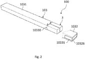
Fig. 2 which shows the installation kit ofFig. 1 during packing of the support beams 31, 32 of thesupport assembly 3 in thesecond packaging 103. The support beams 31, 32 are accommodated side-by-side in thefirst part 1031 of thesecond packaging 103. As can be seen the support beams 31, 32 are enclosed to a large extent in thefirst part 1031, but a portion thereof protrudes from theopening 10310. In this embodiment about 85 % of the support beams 31, 32 are accommodated in thefirst part 1031. The protruding portion of thesupport assembly 3, is seen to be shorter than the second length L2 of thesecond part 1032. The height H1 and width B1 of thefirst part 1031 is selected such that, when accounting for the thickness of the corrugated cardboard, a snug fit between thesupport assembly 3 and the interior surfaces offirst part 1031 is provided. The snug fit between thefirst part 1031 and the support assembly, is preferably snug such that thesupport assembly 3 does not inadvertently slide in thefirst part 1031, during handling, but not so snug that it impedes unpacking of the of packedinstallation kit 1. - Referring now to
Fig. 3a in which thesecond part 1032 of thesecond packaging 103 has been slid on to thesupport assembly 3 and thefirst part 1031 of the second packaging in a telescoping manner, to provide a supply condition of the installation kit. In this way thesecond part 1032 constitutes an outer part of thesecond packaging 103, and an overlap LO is provided between the first 1031 andsecond part 1032. As can be seen the length LO of the overlap in this embodiment substantially amounts to the difference between the length L3 and the sum of first L1 and second length L2. The first 1031 andsecond part 1032 having lengths L1 and L2 as shown inFigs 1 to 3 , would provide an overlap LO in the supply condition for a predefined range of lengths L3 of the support beams 31, 32. The predefined range for the length L3 has an upper limit of less than the sum of the first L1 and second length L2, although a suitable overlap may in practice require the length L3 to be less than e.g. 95% of the length of sum of the first L1 and second length L2. In the embodiment ofFigs 1 to 3 , the length L3 is about 65 % of the sum of the first L1 and second length L2. - For a given range of products applicable within the roof window system, the length L3 will typically vary between about 1000 mm and up to 3000 mm. By selecting the lengths L1 and L2 suitably, the
first part 1031 may have the same length L1, here 1500 mm, throughout the full range, while the length L2 of thesecond part 1032 may be provided in two different sizes, one of 1200 mm to cover the lower sub-range and one of 1500 mm to cover the upper sub-range. - The height H2 and width B2 of the
second part 1032 are selected to be greater than the corresponding height H1 and width B1 of thefirst part 1031, such that, accounting for the corrugated cardboard thickness of the second part, thesecond part 1032 can be slid on to thefirst part 1031 in the telescopic manner. The height H2 and width B2 is preferably further selected such that a snug fit between the interior surfaces of thesecond part 1032 and the exterior surfaces of thefirst part 1031 is provided. In this way the first and second parts of the second packaging is kept together in the supply condition. - It is presently preferred that the length L1 of the of the
first part 1031 is identical for lengths L3 within a pre-defined range, while the length L2 of the second part is selected according in accordance with the length L3, optionally from a few pre-defined lengths L2, such as two pre-defined lengths L2. In the embodiment ofFigs 1 to 3 the first length L1 is longer than the second length L2, which slightly improves the carbon footprint of the second packaging, as thefirst part 1031, has a smaller height H1 and width B1, than thesecond part 1032, thus reducing the amount of material used in the packaging. - The
first part 1031 and thesecond part 1032 may further have fixating means for positioning thefirst part 1031 relative to the support beams 31, 32 and for positioning thesecond part 1032 relative to the support beams 31, 32 and/or thefirst part 1031. InFig. 2 , fixating means in the forms of clamps orstaples 10330 are shown. - For closing off the
end portion 10326, and also theopposite end portion 10316, atape strip 10331 may be provided. -
Fig. 3b shows a view of an embodiment of thesecond packaging 103, in which means are provided to reinforce theend portion 10326. In general, such means may be used individually or in combination. The reinforcement means comprise, non-exhaustively, provision of a plurality of cardboard layers at the end portion, provision of a shock-absorbing element at the end portion, and provision of an extended flap portion configured to overlap an exterior side of the second packaging. - In the embodiment shown, the reinforcement means comprise positioning a shock-absorbing element in the form of a
honeycomb element 10332 between ends of the support beams 31, 32 (not visible) and theend portion 10326 of thesecond packaging 103. Acounterpart honeycomb element 10332 may be provided at theother end portion 10316. - Further reinforcement means comprise the provision of several cardboard layers, in the embodiment shown in
Fig. 3b in the form of threeend flaps extended flap portion 10326d configured to overlap an exterior side of thesecond packaging 103 once theend portion 10326 has been closed. Theother end portion 10316 may be configured in a similar way. There may also be differences between theend portions - Referring now to
Fig. 4 , which shows part of another embodiment of a packedinstallation kit 100 according to the invention. In addition to the second set ofinstallation assemblies 3 packed in thesecond packaging 103, the packedinstallation kit 100 can in some embodiments further comprise a first set ofinstallation assemblies first packaging 101.Fig. 4 shows a set of first installation assemblies packed and accommodated in thefirst packaging 101, which first packaging further accommodatesauxiliary equipment installation assemblies first packaging 101, includes a first installation assembly which is here an insulatingassembly 5, a second installation assembly which is here a stabilizingassembly 6, a third installation assembly which is here asupport assembly 4 including four mounting brackets, a fourth installation assembly which is here a cover assembly comprisingreceiver brackets 7 and a fifth installation assembly which is here acover plate 8. Elements not visible inFig. 1 are denoted by a broken lead line to the respective reference numeral, typically because such elements are hidden in sub-packagings. - The packed
installation kit 100 is inFig. 4 shown in a condition where thefirst packaging 101 is open, allowing the components accommodated therein to be seen. When the packed installation kit is shipped and supplied thefirst packaging 101 will be closed, providing the installation kit in a supply condition. When thefirst packaging 101 is closed it will be a box shaped as rectangular prism of corrugated cardboard with a length extending in the longitudinal direction LP, a width in the width direction WP and a height in the height direction HP. Thefirst packaging 101 is made of corrugated cardboard, which is sometimes called corrugated fibreboard. As can be seen the insulatingassembly 5 is accommodated in thefirst packaging 101 as is, that is the components of the assembly are not packed in a sub-packaging nor is it fixated to the first packaging 110, whereas the mountingbrackets 4,receiver brackets 7 and coverplate 8 are packed in sub-packaging of cardboard or paper material, namelycardboard box 104,cardboard box 107 and paper wrapping 108 respectively. Thefirst packaging 101 further accommodates auxiliary equipment, namely underroofcollar 96 packed in aplastic bag 196,tape roll 96a, avapour barrier collar 97 packed in aplastic bag 197, agutter element 98 and an installation manual (not shown). Theplastic bags skylight window system 1. Further details of the first packaging and the first set of installation assemblies may be found in Applicant's co-pending European patent application filed on the same day as the present application. - Referring now to
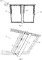
Figs 5 to 8 , the interaction between the installation assemblies of theinstallation kit 100 with theroof window system 1 will be described in more detail. InFigs 5 and 6 , theroof window system 1 is shown from the exterior of the building and inFig. 5 thefirst window unit 11 is mounted in theroof structure 2 and thesecond window unit 12 is being mounted next to thefirst window unit 11. In the mounted condition, theroof window system 1 has a combined width W and a common height H, both of which are seen to extend in parallel with the plane of theroof structure 2. Theroof window system 1 is being installed using asupport assembly 3, mountingbrackets 4, an insulatingassembly 5 and a stabilizingassembly 6. Theupper support beam 31 andlower support beam 32 of thesupport assembly 3 are installed in theroof structure 2 and theroof window system 1 is fastened to them. The length L3 of the twosupport beams roof window system 1. The insulatingframe assembly 5 is a frame surrounding theroof window system 1 in the mounted position and the length of the side members of the frame slightly exceeds the common height H of theroof window system 1. InFig. 6 , bothwindow units roof window system 1 are mounted in theroof structure 2 and auxiliary equipment is being installed. The auxiliary equipment is here anunderroof collar 96 which is mounted around theroof window system 1 and agutter element 98.Figs 7 and 8 show views of theroof window system 1 ofFig. 6 as seen from the interior of the building.Fig. 7 shows the roof window system when thevapour barrier collar 97 is installed after having been unpacked from its sub-packaging 197 which is here a plastic bag.Fig. 8 showsreceiver brackets 7 being installed to receive and mount thecover plate 8. - The
first packaging 101 may be closed and sealed by suitable means including adhesive, tape strips, clamps and/or staples. Closure and sealing of thesecond packaging 103 is carried out as described in the above. Opening of thepackagings - While the
first part 1031 and thesecond part 1032 of thepackaging 103 may be provided in the form presented inFigs 1 to 3b , i.e. folded to form a respective tubular shape, it is also conceivable to use a cardboard blank as a substrate during handling of the support assembly comprising the twosupport beams - Referring now to
Figs 9 and 10 which both show an embodiment of afirst part 1031 of thesecond packaging 103 as a blank, which in a folded state forms thefirst part 1031 of the second packaging.Fig. 9 is a plan view of the blank. The blank is a sheet of corrugated cardboard which is provided with folding lines and cuts which define portions of the blank. At one longitudinal end of the blank there is fourend flaps end portion 10316 of the first part. When the blank is folded the end flaps 10316a, 10316b, 10316c, 10316d overlap to close off theend portion 10316 of thefirst part 1031. Theend portion 10316 will be reinforced as it will be formed of four layers of corrugated cardboard. The end flaps 10316a, 10316b, 10316c, 10316d may be fixated to each other by adhesive or glue between some or all the end flaps. In the embodiment shown, there are no flaps at the opposite end of the blank, and hence thefirst part 1031 folded from the blank will be open at that end, providing theopening 10310. Four folding lines extend longitudinally across the blank, segmenting the blank into atop portion 10311,side portion 10313,base portion 10314,further side portion 10312 andflap portion 10315. Theside portions base portions 10314 have identical widths, whereby thefirst part 1031 in the folded state will have rectangular cross-section. In the folded state of the blank of thefirst part 1031, theflap portion 10315 will overlap partly with the exterior surface of thetop portion 10311, providing overlapping surfaces which may be fixated to each other e.g. by means of an adhesive or glue, or by means of clamps or staples. - In general, the amount of adhesive or glue used in the
first packaging 101 and thesecond packaging 103 is preferably comparatively low, e.g. the mass of adhesive or glue is low compared to the mass of packaging, such as less than 2 %, less than 1.5 %, less than 1 %, less than 0.5 % or even less than 0.1 % by weight of the packaging. - To assist in the folding of the blank the folding lines can comprise a weakening of the corrugated cardboard materials, such as perforations, cuts or the cardboard material having been compressed at the folding line. The blank of the
first part 1031 can be folded to form thefirst part 1031 prior to inserting thecomponents support assembly 3 therein. Alternatively, thecomponents first part 1031 whereupon the blank is folded around the components to form thefirst part 1031 as shown inFig. 10 . Here the components of thesupport assembly 3 are placed side-by-side on thebase portion 10314 of the blank of thefirst part 1031, and subsequently the blank can be folded around the components to form thefirst part 1031 of thesecond packaging 103. - While
Figs 9 and 10 only show a blank to constitute a first blank to form thefirst part 1031 of thesecond packaging 103, it is understood that a similar, second blank can be provided for thesecond part 1032. Such a second blank to form thesecond part 1032 may be folded around the components of thesupport assembly 3 which are accommodated in the first part, similarly to the process ofFig. 10 , to provide the supply condition of the packedinstallation kit 100. - Alternatively, it is possible to apply some of the principles underlying the present invention independently to a blank having such a length that the packaging to be formed is able accommodate the full length of the components of the
support assembly 3. In particular, the means for reinforcing the end portions are applicable. A plurality of end flaps including two, three or four end flaps may be provided at either end of the blank. The use of an overlapping flap portion, corresponding to theflap portion 10315, to cover the full length of such a packaging is conceivable. Fixating means in the forms of clamps or staples may be applied throughout the length of the packaging, partly to strengthen the coherence of the packaging itself, partly to provide additional retention of the components of the second set of installation assemblies in the length direction of the packaging, thus mitigating the effect of possible pressure or impact acting on the end portions in case the support beams move in the longitudinal direction of the second packaging. -
- 1
- roof window system
11 first window unit
12 second window unit - 2
- roof structure
21 rafter
22 batten - 3
- support assembly
31 upper support beam
32 lower support beam - 4
- mounting bracket
- 5
- insulating assembly
- 6
- stabilizing assembly
- 7
- receiver brackets
- 8
- cover plate
- 96
- underroof collar
- 96a
- tape roll
- 97
- vapour barrier collar
- 98
- gutter element
- 100
- packed installation kit
- 101
- first packaging
- 103
- second packaging
1031 first part of second packaging
10310 opening
10311 top portion
10312 side portion
10313 side portion
10314 base portion
10315 flap portion
10316 end portion
10316a end flap
10316b end flap
10316c end flap
10316d end flap
1032 second part of second packaging
10320 opening
10326 end portion
10326a end flap
10326b end flap
10326c end flap
10326d extended end flap portion
10330 staples
10331 tape strip
10332 honeycomb element - 104
- sub-packaging for mounting
brackets 4 - 107
- sub-packaging for
receiver brackets 7 - 108
- sub-packaging for
cover plate 8 - 196
- sub-packaging for
underroof collar 96 - 197
- sub-packaging for
vapour barrier collar 97 - H
- common height of
roof window system 1 in mounted condition - W
- combined width of
roof window system 1 in mounted condition - B1
- first width (of
first part 1031 of second packaging 103) - H1
- first height (of
first part 1031 of second packaging 103) - L1
- first length (of
first part 1031 of second packaging 103) - B2
- second width (of
second part 1032 of second packaging 103) - H2
- second height (of
second part 1032 of second packaging 103) - L2
- second length (of
second part 1032 of second packaging 103) - B3
- width of second set of installation assemblies (support assembly 3)
- H3
- height of second set of installation assemblies (support assembly 3)
- L3
- length of second set of installation assemblies (support assembly 3)
- HP
- height direction of
first packaging 101 - LP
- longitudinal direction of
first packaging 101 - WP
- width direction of
first packaging 101 - LO
- overlap between
first part 1031 andsecond part 1032 ofsecond packaging 103
Claims (15)
- A packed installation kit (100) for use in the installation of a roof window system comprising two window units (11, 12) and configured to be built in side by side in an inclined roof structure (2) such that the roof window system defines a common height (H) and a combined width (W) in the mounted condition, said installation kit (100) comprising a number of installation assemblies (3, 4, 5, 6, 7, 8), each including one or more components, and optionally auxiliary equipment (96, 96A, 97, 98),characterised in thatthe components of a second set of installation assemblies (3) of the installation kit (100) comprise two support beams (31, 32) accommodated side-by-side in a second packaging (103) comprising a rectangular telescopic tube packaging having two parts (1031, 1032) of corrugated cardboard, a first part (1031) of the second packaging (103) having a first length (L1) extending between an end portion (10316) and an opening (10310), and a second part (1032) having a second length (L2) extending between an end portion (10326) and an opening (10320), and the support beams (31, 32) having a length (L3) within a pre-defined range, thatthe total length of the second packaging (103) as defined by the sum of the length (L1) of the first part (1031) and the length (L2) of the second part (1032) exceeds the length (L3) of the support beams (31, 32) such that an overlap (LO) between the second part (1032) and the first part (1031) is provided in a supply condition of the installation kit (100) within said predefined range of lengths of the support beams (31, 32) of the second set of installation assemblies (3), and thatmeans are provided to reinforce at least one of the end portions (10316, 10326), said means being selected from the group comprising- provision of a plurality of cardboard layers at the end portion,- provision of a shock-absorbing element at the end portion, and- provision of an extended flap portion configured to overlap an exterior side of the second packaging (103).
- A packed installation kit (100) according to claim 1, wherein the first part (1031) of the second packaging (103) constitutes an inner part in the supply condition, the first part (1031) having such a width (B1) and height (H1) for a given material thickness of the corrugated cardboard that a snug fit between the interior of the first part (1031) of the second packaging (103) and the two support beams (31, 32) of the support assembly (3) accommodated side-by-side, the two support beams (31, 32) of the support assembly (3) preferably having identical heights (H3) and a total width (B3) which is the double of each support beam (31, 32).
- A packed installation kit (100) according to claim 2, wherein the second part (1032) of the second packaging (103) constitutes an outer part in the supply condition, the second part (1032) having such a width (B2) and height (H2) for a given material thickness of the corrugated cardboard that a snug fit between the interior of the second part (1032) and the exterior of the first part (1031) is provided.
- A packed installation kit (100) according to any one of the preceding claims, wherein the length (L1) of the first part (1031) of the second packaging (103) is longer than or equal to the length (L2) of the second part (1032) of the second packaging (103).
- A packed installation kit (100) according to any one of the preceding claims, wherein the length (L1) of the first part (1031) of the second packaging (103) is identical for various lengths (L3) of the support beams (31, 32) within said pre-defined range, the length (L1) of the first part (1031) of the second packaging (103) being preferably 1400 to 1600 mm, more preferably about 1500 mm.
- A packed installation kit (100) according to claim 5, wherein the length (L2) of the second part (1031) of the second packaging (103) is selected in accordance with the length (L3) of the support beams (31, 32), preferably such that a length is selected for a respective sub-range within said pre-defined range, the length (L2) of the second part (1032) of the second packaging (103) in a shorter sub-range being preferably 1000 to 1400 mm, more preferably about 1200 mm, and wherein the length (L2) of the second part (1032) of the second packaging (103) in a longer sub-range is preferably 1400 to 1600 mm, more preferably about 1500 mm.
- A packed installation kit (100) according to any one of the preceding claims, wherein fixating means (10330) are provided for positioning at least the first part (1031) of the second packaging (103) relative to the two support beams (31, 32) of the support assembly (3), preferably also fixating means for positioning the second part (1032) of the second packaging (103) relative to the first part (1031) and/or to the two support beams (31, 32).
- A packed installation kit (100) according to any one of the preceding claims, wherein the reinforcement means comprise positioning a shock-absorbing element comprising at least one honeycomb element (10332) between ends of the support beams (31, 32) and the end portion (10326, 10316) of the second packaging (103), preferably one honeycomb element (10332) being provided at each end portion (10326, 10316).
- A packed installation kit according to any one of the preceding claims, wherein the reinforcement means comprise the provision of a plurality of cardboard layers in the form of two, three or four end flaps (10316a, 10316b, 10316c, 10316c; 10326a, 10326b, 10326c), optionally combined with an extended flap portion (10326d) configured to overlap an exterior side of the second packaging.
- A packed installation kit according to any one of the preceding claims, wherein the components of a first set of installation assemblies (4, 5, 6, 7, 8) of the installation kit (100) are accommodated in a first packaging (101) comprising a box shaped as a rectangular prism, preferably of corrugated cardboard, having a length in a longitudinal direction (LP), a width in a width direction (WP) and a height in a height direction (HP) to provide a supply condition of the installation kit, and wherein the components of the first set of installation assemblies (4, 5, 6, 7, 8) of the installation kit (100) are accommodated in the first packaging (101) either as they are, or partially or entirely packed in a sub-packaging (104, 1063, 1064, 107, 108) of cardboard or paper material.
- A method of packaging components of a set of installation assemblies of an installation kit in a packaging, comprising the steps of:providing at least one blank having such dimensions that it is able to form the packaging in a folded state,providing reinforcement means,placing the components in the packaging, andapplying the reinforcement means to provide a supply condition of the packed installation kit.
- A method of packaging components according to claim 11, comprising the steps of:providing two blanks which in a folded state form a first part (1031) and a second part (1032), respectively, of the packaging (103),placing the components in the first part (1031),overlapping the second part (1032) with the first part (1031) to provide a supply condition of the packed installation kit.
- A method according to claim 11 or 12, wherein the components are placed on the at least one blank before at least some of the folding operations have been carried out.
- A method according to claims 12 and 13, wherein the components (31, 32) are placed on the first blank which in the folded state forms the first part (1031), before the folding is carried out, following which the components which are at least partially enclosed by the first part (1031) are either positioned on the second blank, which in the folded state forms the second part (1032) before folding is carried out, or the second blank is formed to the second part (1032) before connecting the second part (1032) with the first part (1031) and the components.
- A method according to any one of claims 11 to 14, wherein the step of providing reinforcement means comprise one or more of the following operations:- providing the at least one blank with a plurality of cardboard layers,- providing at least one shock-absorbing element,- providing the at least one blank with an extended flap portion at one or both longitudinal ends of the blank.
Applications Claiming Priority (1)
| Application Number | Priority Date | Filing Date | Title |
|---|---|---|---|
| DKPA202170243 | 2021-05-12 |
Publications (4)
| Publication Number | Publication Date |
|---|---|
| EP4089031A2 true EP4089031A2 (en) | 2022-11-16 |
| EP4089031A3 EP4089031A3 (en) | 2022-12-07 |
| EP4089031C0 EP4089031C0 (en) | 2024-01-24 |
| EP4089031B1 EP4089031B1 (en) | 2024-01-24 |
Family
ID=81648807
Family Applications (1)
| Application Number | Title | Priority Date | Filing Date |
|---|---|---|---|
| EP22172945.2A Active EP4089031B1 (en) | 2021-05-12 | 2022-05-12 | Packed installation kit comprising an installation assembly with support beams as components |
Country Status (3)
| Country | Link |
|---|---|
| EP (1) | EP4089031B1 (en) |
| HU (1) | HUE065533T2 (en) |
| PL (1) | PL4089031T3 (en) |
Family Cites Families (4)
| Publication number | Priority date | Publication date | Assignee | Title |
|---|---|---|---|---|
| DE1906464U (en) * | 1964-10-06 | 1964-12-10 | Europa Carton Ag | PACKAGING PADDING. |
| DK200500501A (en) * | 2005-04-08 | 2006-10-09 | Vkr Holding As | Method, retaining member and packaging for packaging a product comprising a plurality of sub-components |
| EP2778086B1 (en) * | 2013-03-11 | 2017-04-19 | Sanofi-Aventis Deutschland GmbH | Packaging assembly to accommodate at least two items |
| ITUB20160095A1 (en) * | 2016-02-03 | 2017-08-03 | Arti Grafiche Reggiane & Lai S P A | BOX WITH LIGHTING DEVICE |
-
2022
- 2022-05-12 PL PL22172945.2T patent/PL4089031T3/en unknown
- 2022-05-12 HU HUE22172945A patent/HUE065533T2/en unknown
- 2022-05-12 EP EP22172945.2A patent/EP4089031B1/en active Active
Also Published As
| Publication number | Publication date |
|---|---|
| HUE065533T2 (en) | 2024-05-28 |
| EP4089031C0 (en) | 2024-01-24 |
| EP4089031B1 (en) | 2024-01-24 |
| EP4089031A3 (en) | 2022-12-07 |
| PL4089031T3 (en) | 2024-06-24 |
Similar Documents
| Publication | Publication Date | Title |
|---|---|---|
| US20140238879A1 (en) | Packaging for a window and a method for packing | |
| EP4089025B1 (en) | A packed roof window | |
| US5531166A (en) | Corrugated fiberboard riser | |
| EP4089031B1 (en) | Packed installation kit comprising an installation assembly with support beams as components | |
| EP4089034B1 (en) | Packed installation kit comprising installation assemblies for a roof window system | |
| EP4412922B1 (en) | Packed roof window product, a method for packing a packed roof window product, and a method of unpacking a packed roof window product | |
| CZ37862U1 (en) | Assembly kit packaging containing assembly assemblies for the skylight system | |
| US20210139194A1 (en) | Shipping pallet sleeve system and methods | |
| EP4091959A1 (en) | A packed roof window, a ventilation flap retainer, and use of a ventilation flap retainer | |
| MX2008016403A (en) | Container for glass products. | |
| CZ37830U1 (en) | A carton assembly containing a carton containing a sunroof and packaging components to protect and hold the sunroof components | |
| US8141708B2 (en) | Container for glass products | |
| DK180083B1 (en) | A method for packing a pre-assembled product for use at a roof in removable second packaging means. | |
| EP4269262A1 (en) | Container for repeated uses | |
| EP1671895A2 (en) | Transport unit for rock wool products, in particular rock wool insulation panels, arranged in a stack | |
| WO2010096536A2 (en) | Carton and carton blank corner structure | |
| DK181780B1 (en) | A packed kit of flashing and/or covering members for a roof window and a method for packing a kit of flashing and/or covering members | |
| EP1591368B1 (en) | Device for handling of transport units for insulating elements | |
| EP4368530A1 (en) | A method for packaging a roof window and a packed roof window | |
| EP4303144A1 (en) | Packing box made of natural fibre board | |
| DK181313B1 (en) | Packed roof window products | |
| US20260048894A1 (en) | Blank configured to be erected into a package and a package formed by such a blank | |
| FI12316U1 (en) | Blank for a recycling container and a recycling container | |
| FI13264Y1 (en) | Packaging box of natural fibreboard | |
| JP2025082515A (en) | packaging material |
Legal Events
| Date | Code | Title | Description |
|---|---|---|---|
| PUAI | Public reference made under article 153(3) epc to a published international application that has entered the european phase |
Free format text: ORIGINAL CODE: 0009012 |
|
| STAA | Information on the status of an ep patent application or granted ep patent |
Free format text: STATUS: THE APPLICATION HAS BEEN PUBLISHED |
|
| PUAL | Search report despatched |
Free format text: ORIGINAL CODE: 0009013 |
|
| AK | Designated contracting states |
Kind code of ref document: A2 Designated state(s): AL AT BE BG CH CY CZ DE DK EE ES FI FR GB GR HR HU IE IS IT LI LT LU LV MC MK MT NL NO PL PT RO RS SE SI SK SM TR |
|
| AK | Designated contracting states |
Kind code of ref document: A3 Designated state(s): AL AT BE BG CH CY CZ DE DK EE ES FI FR GB GR HR HU IE IS IT LI LT LU LV MC MK MT NL NO PL PT RO RS SE SI SK SM TR |
|
| RIC1 | Information provided on ipc code assigned before grant |
Ipc: B65D 5/02 20060101ALI20221028BHEP Ipc: B65D 81/127 20060101ALI20221028BHEP Ipc: B65D 81/107 20060101ALI20221028BHEP Ipc: B65D 5/68 20060101ALI20221028BHEP Ipc: B65D 5/50 20060101ALI20221028BHEP Ipc: B65D 85/64 20060101ALI20221028BHEP Ipc: B65D 77/04 20060101AFI20221028BHEP |
|
| STAA | Information on the status of an ep patent application or granted ep patent |
Free format text: STATUS: REQUEST FOR EXAMINATION WAS MADE |
|
| 17P | Request for examination filed |
Effective date: 20230531 |
|
| RBV | Designated contracting states (corrected) |
Designated state(s): AL AT BE BG CH CY CZ DE DK EE ES FI FR GB GR HR HU IE IS IT LI LT LU LV MC MK MT NL NO PL PT RO RS SE SI SK SM TR |
|
| GRAP | Despatch of communication of intention to grant a patent |
Free format text: ORIGINAL CODE: EPIDOSNIGR1 |
|
| STAA | Information on the status of an ep patent application or granted ep patent |
Free format text: STATUS: GRANT OF PATENT IS INTENDED |
|
| INTG | Intention to grant announced |
Effective date: 20231031 |
|
| GRAS | Grant fee paid |
Free format text: ORIGINAL CODE: EPIDOSNIGR3 |
|
| GRAA | (expected) grant |
Free format text: ORIGINAL CODE: 0009210 |
|
| STAA | Information on the status of an ep patent application or granted ep patent |
Free format text: STATUS: THE PATENT HAS BEEN GRANTED |
|
| AK | Designated contracting states |
Kind code of ref document: B1 Designated state(s): AL AT BE BG CH CY CZ DE DK EE ES FI FR GB GR HR HU IE IS IT LI LT LU LV MC MK MT NL NO PL PT RO RS SE SI SK SM TR |
|
| REG | Reference to a national code |
Ref country code: GB Ref legal event code: FG4D |
|
| REG | Reference to a national code |
Ref country code: CH Ref legal event code: EP |
|
| REG | Reference to a national code |
Ref country code: IE Ref legal event code: FG4D |
|
| REG | Reference to a national code |
Ref country code: DE Ref legal event code: R096 Ref document number: 602022001662 Country of ref document: DE |
|
| U01 | Request for unitary effect filed |
Effective date: 20240209 |
|
| U07 | Unitary effect registered |
Designated state(s): AT BE BG DE DK EE FI FR IT LT LU LV MT NL PT SE SI Effective date: 20240220 |
|
| U20 | Renewal fee for the european patent with unitary effect paid |
Year of fee payment: 3 Effective date: 20240408 |
|
| REG | Reference to a national code |
Ref country code: HU Ref legal event code: AG4A Ref document number: E065533 Country of ref document: HU |
|
| PG25 | Lapsed in a contracting state [announced via postgrant information from national office to epo] |
Ref country code: IS Free format text: LAPSE BECAUSE OF FAILURE TO SUBMIT A TRANSLATION OF THE DESCRIPTION OR TO PAY THE FEE WITHIN THE PRESCRIBED TIME-LIMIT Effective date: 20240524 |
|
| PG25 | Lapsed in a contracting state [announced via postgrant information from national office to epo] |
Ref country code: GR Free format text: LAPSE BECAUSE OF FAILURE TO SUBMIT A TRANSLATION OF THE DESCRIPTION OR TO PAY THE FEE WITHIN THE PRESCRIBED TIME-LIMIT Effective date: 20240425 |
|
| PG25 | Lapsed in a contracting state [announced via postgrant information from national office to epo] |
Ref country code: RS Free format text: LAPSE BECAUSE OF FAILURE TO SUBMIT A TRANSLATION OF THE DESCRIPTION OR TO PAY THE FEE WITHIN THE PRESCRIBED TIME-LIMIT Effective date: 20240424 Ref country code: HR Free format text: LAPSE BECAUSE OF FAILURE TO SUBMIT A TRANSLATION OF THE DESCRIPTION OR TO PAY THE FEE WITHIN THE PRESCRIBED TIME-LIMIT Effective date: 20240124 |
|
| PG25 | Lapsed in a contracting state [announced via postgrant information from national office to epo] |
Ref country code: ES Free format text: LAPSE BECAUSE OF FAILURE TO SUBMIT A TRANSLATION OF THE DESCRIPTION OR TO PAY THE FEE WITHIN THE PRESCRIBED TIME-LIMIT Effective date: 20240124 |
|
| PG25 | Lapsed in a contracting state [announced via postgrant information from national office to epo] |
Ref country code: RS Free format text: LAPSE BECAUSE OF FAILURE TO SUBMIT A TRANSLATION OF THE DESCRIPTION OR TO PAY THE FEE WITHIN THE PRESCRIBED TIME-LIMIT Effective date: 20240424 Ref country code: NO Free format text: LAPSE BECAUSE OF FAILURE TO SUBMIT A TRANSLATION OF THE DESCRIPTION OR TO PAY THE FEE WITHIN THE PRESCRIBED TIME-LIMIT Effective date: 20240424 Ref country code: IS Free format text: LAPSE BECAUSE OF FAILURE TO SUBMIT A TRANSLATION OF THE DESCRIPTION OR TO PAY THE FEE WITHIN THE PRESCRIBED TIME-LIMIT Effective date: 20240524 Ref country code: HR Free format text: LAPSE BECAUSE OF FAILURE TO SUBMIT A TRANSLATION OF THE DESCRIPTION OR TO PAY THE FEE WITHIN THE PRESCRIBED TIME-LIMIT Effective date: 20240124 Ref country code: GR Free format text: LAPSE BECAUSE OF FAILURE TO SUBMIT A TRANSLATION OF THE DESCRIPTION OR TO PAY THE FEE WITHIN THE PRESCRIBED TIME-LIMIT Effective date: 20240425 Ref country code: ES Free format text: LAPSE BECAUSE OF FAILURE TO SUBMIT A TRANSLATION OF THE DESCRIPTION OR TO PAY THE FEE WITHIN THE PRESCRIBED TIME-LIMIT Effective date: 20240124 |
|
| PG25 | Lapsed in a contracting state [announced via postgrant information from national office to epo] |
Ref country code: SM Free format text: LAPSE BECAUSE OF FAILURE TO SUBMIT A TRANSLATION OF THE DESCRIPTION OR TO PAY THE FEE WITHIN THE PRESCRIBED TIME-LIMIT Effective date: 20240124 |
|
| REG | Reference to a national code |
Ref country code: DE Ref legal event code: R097 Ref document number: 602022001662 Country of ref document: DE |
|
| PG25 | Lapsed in a contracting state [announced via postgrant information from national office to epo] |
Ref country code: SK Free format text: LAPSE BECAUSE OF FAILURE TO SUBMIT A TRANSLATION OF THE DESCRIPTION OR TO PAY THE FEE WITHIN THE PRESCRIBED TIME-LIMIT Effective date: 20240124 |
|
| PG25 | Lapsed in a contracting state [announced via postgrant information from national office to epo] |
Ref country code: SM Free format text: LAPSE BECAUSE OF FAILURE TO SUBMIT A TRANSLATION OF THE DESCRIPTION OR TO PAY THE FEE WITHIN THE PRESCRIBED TIME-LIMIT Effective date: 20240124 Ref country code: SK Free format text: LAPSE BECAUSE OF FAILURE TO SUBMIT A TRANSLATION OF THE DESCRIPTION OR TO PAY THE FEE WITHIN THE PRESCRIBED TIME-LIMIT Effective date: 20240124 |
|
| PLBE | No opposition filed within time limit |
Free format text: ORIGINAL CODE: 0009261 |
|
| STAA | Information on the status of an ep patent application or granted ep patent |
Free format text: STATUS: NO OPPOSITION FILED WITHIN TIME LIMIT |
|
| 26N | No opposition filed |
Effective date: 20241025 |
|
| PG25 | Lapsed in a contracting state [announced via postgrant information from national office to epo] |
Ref country code: MC Free format text: LAPSE BECAUSE OF FAILURE TO SUBMIT A TRANSLATION OF THE DESCRIPTION OR TO PAY THE FEE WITHIN THE PRESCRIBED TIME-LIMIT Effective date: 20240124 |
|
| PG25 | Lapsed in a contracting state [announced via postgrant information from national office to epo] |
Ref country code: MC Free format text: LAPSE BECAUSE OF FAILURE TO SUBMIT A TRANSLATION OF THE DESCRIPTION OR TO PAY THE FEE WITHIN THE PRESCRIBED TIME-LIMIT Effective date: 20240124 |
|
| PG25 | Lapsed in a contracting state [announced via postgrant information from national office to epo] |
Ref country code: IE Free format text: LAPSE BECAUSE OF NON-PAYMENT OF DUE FEES Effective date: 20240512 |
|
| U20 | Renewal fee for the european patent with unitary effect paid |
Year of fee payment: 4 Effective date: 20250407 |
|
| PGFP | Annual fee paid to national office [announced via postgrant information from national office to epo] |
Ref country code: PL Payment date: 20250414 Year of fee payment: 4 |
|
| PGFP | Annual fee paid to national office [announced via postgrant information from national office to epo] |
Ref country code: HU Payment date: 20250429 Year of fee payment: 4 |
|
| PGFP | Annual fee paid to national office [announced via postgrant information from national office to epo] |
Ref country code: CH Payment date: 20250601 Year of fee payment: 4 |
|
| PGFP | Annual fee paid to national office [announced via postgrant information from national office to epo] |
Ref country code: CZ Payment date: 20250423 Year of fee payment: 4 |
|
| PG25 | Lapsed in a contracting state [announced via postgrant information from national office to epo] |
Ref country code: RO Free format text: LAPSE BECAUSE OF FAILURE TO SUBMIT A TRANSLATION OF THE DESCRIPTION OR TO PAY THE FEE WITHIN THE PRESCRIBED TIME-LIMIT Effective date: 20240124 |
|
| PG25 | Lapsed in a contracting state [announced via postgrant information from national office to epo] |
Ref country code: CY Free format text: LAPSE BECAUSE OF FAILURE TO SUBMIT A TRANSLATION OF THE DESCRIPTION OR TO PAY THE FEE WITHIN THE PRESCRIBED TIME-LIMIT; INVALID AB INITIO Effective date: 20220512 |
|
| PGFP | Annual fee paid to national office [announced via postgrant information from national office to epo] |
Ref country code: GB Payment date: 20260312 Year of fee payment: 5 |