EP4088972A1 - Vehicle lighting device - Google Patents
Vehicle lighting device Download PDFInfo
- Publication number
- EP4088972A1 EP4088972A1 EP22165504.6A EP22165504A EP4088972A1 EP 4088972 A1 EP4088972 A1 EP 4088972A1 EP 22165504 A EP22165504 A EP 22165504A EP 4088972 A1 EP4088972 A1 EP 4088972A1
- Authority
- EP
- European Patent Office
- Prior art keywords
- led
- light
- optical
- lighting device
- inner layer
- Prior art date
- Legal status (The legal status is an assumption and is not a legal conclusion. Google has not performed a legal analysis and makes no representation as to the accuracy of the status listed.)
- Withdrawn
Links
Images



Classifications
-
- B—PERFORMING OPERATIONS; TRANSPORTING
- B60—VEHICLES IN GENERAL
- B60Q—ARRANGEMENT OF SIGNALLING OR LIGHTING DEVICES, THE MOUNTING OR SUPPORTING THEREOF OR CIRCUITS THEREFOR, FOR VEHICLES IN GENERAL
- B60Q3/00—Arrangement of lighting devices for vehicle interiors; Lighting devices specially adapted for vehicle interiors
- B60Q3/50—Mounting arrangements
- B60Q3/54—Lighting devices embedded in interior trim, e.g. in roof liners
-
- B—PERFORMING OPERATIONS; TRANSPORTING
- B32—LAYERED PRODUCTS
- B32B—LAYERED PRODUCTS, i.e. PRODUCTS BUILT-UP OF STRATA OF FLAT OR NON-FLAT, e.g. CELLULAR OR HONEYCOMB, FORM
- B32B27/00—Layered products comprising a layer of synthetic resin
- B32B27/06—Layered products comprising a layer of synthetic resin as the main or only constituent of a layer, which is next to another layer of the same or of a different material
-
- B—PERFORMING OPERATIONS; TRANSPORTING
- B32—LAYERED PRODUCTS
- B32B—LAYERED PRODUCTS, i.e. PRODUCTS BUILT-UP OF STRATA OF FLAT OR NON-FLAT, e.g. CELLULAR OR HONEYCOMB, FORM
- B32B3/00—Layered products comprising a layer with external or internal discontinuities or unevennesses, or a layer of non-planar shape; Layered products comprising a layer having particular features of form
- B32B3/26—Layered products comprising a layer with external or internal discontinuities or unevennesses, or a layer of non-planar shape; Layered products comprising a layer having particular features of form characterised by a particular shape of the outline of the cross-section of a continuous layer; characterised by a layer with cavities or internal voids ; characterised by an apertured layer
- B32B3/266—Layered products comprising a layer with external or internal discontinuities or unevennesses, or a layer of non-planar shape; Layered products comprising a layer having particular features of form characterised by a particular shape of the outline of the cross-section of a continuous layer; characterised by a layer with cavities or internal voids ; characterised by an apertured layer characterised by an apertured layer, the apertures going through the whole thickness of the layer, e.g. expanded metal, perforated layer, slit layer regular cells B32B3/12
-
- B—PERFORMING OPERATIONS; TRANSPORTING
- B32—LAYERED PRODUCTS
- B32B—LAYERED PRODUCTS, i.e. PRODUCTS BUILT-UP OF STRATA OF FLAT OR NON-FLAT, e.g. CELLULAR OR HONEYCOMB, FORM
- B32B5/00—Layered products characterised by the non- homogeneity or physical structure, i.e. comprising a fibrous, filamentary, particulate or foam layer; Layered products characterised by having a layer differing constitutionally or physically in different parts
- B32B5/02—Layered products characterised by the non- homogeneity or physical structure, i.e. comprising a fibrous, filamentary, particulate or foam layer; Layered products characterised by having a layer differing constitutionally or physically in different parts characterised by structural features of a fibrous or filamentary layer
- B32B5/022—Non-woven fabric
-
- B—PERFORMING OPERATIONS; TRANSPORTING
- B32—LAYERED PRODUCTS
- B32B—LAYERED PRODUCTS, i.e. PRODUCTS BUILT-UP OF STRATA OF FLAT OR NON-FLAT, e.g. CELLULAR OR HONEYCOMB, FORM
- B32B5/00—Layered products characterised by the non- homogeneity or physical structure, i.e. comprising a fibrous, filamentary, particulate or foam layer; Layered products characterised by having a layer differing constitutionally or physically in different parts
- B32B5/18—Layered products characterised by the non- homogeneity or physical structure, i.e. comprising a fibrous, filamentary, particulate or foam layer; Layered products characterised by having a layer differing constitutionally or physically in different parts characterised by features of a layer of foamed material
-
- B—PERFORMING OPERATIONS; TRANSPORTING
- B32—LAYERED PRODUCTS
- B32B—LAYERED PRODUCTS, i.e. PRODUCTS BUILT-UP OF STRATA OF FLAT OR NON-FLAT, e.g. CELLULAR OR HONEYCOMB, FORM
- B32B9/00—Layered products comprising a layer of a particular substance not covered by groups B32B11/00 - B32B29/00
- B32B9/02—Layered products comprising a layer of a particular substance not covered by groups B32B11/00 - B32B29/00 comprising animal or vegetable substances, e.g. cork, bamboo, starch
- B32B9/025—Layered products comprising a layer of a particular substance not covered by groups B32B11/00 - B32B29/00 comprising animal or vegetable substances, e.g. cork, bamboo, starch comprising leather
-
- B—PERFORMING OPERATIONS; TRANSPORTING
- B60—VEHICLES IN GENERAL
- B60Q—ARRANGEMENT OF SIGNALLING OR LIGHTING DEVICES, THE MOUNTING OR SUPPORTING THEREOF OR CIRCUITS THEREFOR, FOR VEHICLES IN GENERAL
- B60Q3/00—Arrangement of lighting devices for vehicle interiors; Lighting devices specially adapted for vehicle interiors
- B60Q3/20—Arrangement of lighting devices for vehicle interiors; Lighting devices specially adapted for vehicle interiors for lighting specific fittings of passenger or driving compartments; mounted on specific fittings of passenger or driving compartments
-
- B—PERFORMING OPERATIONS; TRANSPORTING
- B60—VEHICLES IN GENERAL
- B60Q—ARRANGEMENT OF SIGNALLING OR LIGHTING DEVICES, THE MOUNTING OR SUPPORTING THEREOF OR CIRCUITS THEREFOR, FOR VEHICLES IN GENERAL
- B60Q3/00—Arrangement of lighting devices for vehicle interiors; Lighting devices specially adapted for vehicle interiors
- B60Q3/60—Arrangement of lighting devices for vehicle interiors; Lighting devices specially adapted for vehicle interiors characterised by optical aspects
-
- B—PERFORMING OPERATIONS; TRANSPORTING
- B60—VEHICLES IN GENERAL
- B60Q—ARRANGEMENT OF SIGNALLING OR LIGHTING DEVICES, THE MOUNTING OR SUPPORTING THEREOF OR CIRCUITS THEREFOR, FOR VEHICLES IN GENERAL
- B60Q3/00—Arrangement of lighting devices for vehicle interiors; Lighting devices specially adapted for vehicle interiors
- B60Q3/70—Arrangement of lighting devices for vehicle interiors; Lighting devices specially adapted for vehicle interiors characterised by the purpose
- B60Q3/74—Arrangement of lighting devices for vehicle interiors; Lighting devices specially adapted for vehicle interiors characterised by the purpose for overall compartment lighting; for overall compartment lighting in combination with specific lighting, e.g. room lamps with reading lamps
- B60Q3/745—Arrangement of lighting devices for vehicle interiors; Lighting devices specially adapted for vehicle interiors characterised by the purpose for overall compartment lighting; for overall compartment lighting in combination with specific lighting, e.g. room lamps with reading lamps using lighting panels or mats, e.g. electro-luminescent panels, LED mats
-
- F—MECHANICAL ENGINEERING; LIGHTING; HEATING; WEAPONS; BLASTING
- F21—LIGHTING
- F21V—FUNCTIONAL FEATURES OR DETAILS OF LIGHTING DEVICES OR SYSTEMS THEREOF; STRUCTURAL COMBINATIONS OF LIGHTING DEVICES WITH OTHER ARTICLES, NOT OTHERWISE PROVIDED FOR
- F21V5/00—Refractors for light sources
- F21V5/007—Array of lenses or refractors for a cluster of light sources, e.g. for arrangement of multiple light sources in one plane
-
- G—PHYSICS
- G09—EDUCATION; CRYPTOGRAPHY; DISPLAY; ADVERTISING; SEALS
- G09F—DISPLAYING; ADVERTISING; SIGNS; LABELS OR NAME-PLATES; SEALS
- G09F21/00—Mobile visual advertising
- G09F21/04—Mobile visual advertising by land vehicles
-
- G—PHYSICS
- G09—EDUCATION; CRYPTOGRAPHY; DISPLAY; ADVERTISING; SEALS
- G09G—ARRANGEMENTS OR CIRCUITS FOR CONTROL OF INDICATING DEVICES USING STATIC MEANS TO PRESENT VARIABLE INFORMATION
- G09G3/00—Control arrangements or circuits, of interest only in connection with visual indicators other than cathode-ray tubes
- G09G3/20—Control arrangements or circuits, of interest only in connection with visual indicators other than cathode-ray tubes for presentation of an assembly of a number of characters, e.g. a page, by composing the assembly by combination of individual elements arranged in a matrix no fixed position being assigned to or needed to be assigned to the individual characters or partial characters
- G09G3/22—Control arrangements or circuits, of interest only in connection with visual indicators other than cathode-ray tubes for presentation of an assembly of a number of characters, e.g. a page, by composing the assembly by combination of individual elements arranged in a matrix no fixed position being assigned to or needed to be assigned to the individual characters or partial characters using controlled light sources
- G09G3/30—Control arrangements or circuits, of interest only in connection with visual indicators other than cathode-ray tubes for presentation of an assembly of a number of characters, e.g. a page, by composing the assembly by combination of individual elements arranged in a matrix no fixed position being assigned to or needed to be assigned to the individual characters or partial characters using controlled light sources using electroluminescent panels
- G09G3/32—Control arrangements or circuits, of interest only in connection with visual indicators other than cathode-ray tubes for presentation of an assembly of a number of characters, e.g. a page, by composing the assembly by combination of individual elements arranged in a matrix no fixed position being assigned to or needed to be assigned to the individual characters or partial characters using controlled light sources using electroluminescent panels semiconductive, e.g. using light-emitting diodes [LED]
-
- H—ELECTRICITY
- H05—ELECTRIC TECHNIQUES NOT OTHERWISE PROVIDED FOR
- H05K—PRINTED CIRCUITS; CASINGS OR CONSTRUCTIONAL DETAILS OF ELECTRIC APPARATUS; MANUFACTURE OF ASSEMBLAGES OF ELECTRICAL COMPONENTS
- H05K1/00—Printed circuits
- H05K1/18—Printed circuits structurally associated with non-printed electric components
- H05K1/189—Printed circuits structurally associated with non-printed electric components characterised by the use of flexible or folded printed circuits
-
- H—ELECTRICITY
- H10—SEMICONDUCTOR DEVICES; ELECTRIC SOLID-STATE DEVICES NOT OTHERWISE PROVIDED FOR
- H10W—GENERIC PACKAGES, INTERCONNECTIONS, CONNECTORS OR OTHER CONSTRUCTIONAL DETAILS OF DEVICES COVERED BY CLASS H10
- H10W90/00—Package configurations
-
- B—PERFORMING OPERATIONS; TRANSPORTING
- B32—LAYERED PRODUCTS
- B32B—LAYERED PRODUCTS, i.e. PRODUCTS BUILT-UP OF STRATA OF FLAT OR NON-FLAT, e.g. CELLULAR OR HONEYCOMB, FORM
- B32B2451/00—Decorative or ornamental articles
-
- B—PERFORMING OPERATIONS; TRANSPORTING
- B32—LAYERED PRODUCTS
- B32B—LAYERED PRODUCTS, i.e. PRODUCTS BUILT-UP OF STRATA OF FLAT OR NON-FLAT, e.g. CELLULAR OR HONEYCOMB, FORM
- B32B2457/00—Electrical equipment
-
- B—PERFORMING OPERATIONS; TRANSPORTING
- B32—LAYERED PRODUCTS
- B32B—LAYERED PRODUCTS, i.e. PRODUCTS BUILT-UP OF STRATA OF FLAT OR NON-FLAT, e.g. CELLULAR OR HONEYCOMB, FORM
- B32B2551/00—Optical elements
-
- B—PERFORMING OPERATIONS; TRANSPORTING
- B32—LAYERED PRODUCTS
- B32B—LAYERED PRODUCTS, i.e. PRODUCTS BUILT-UP OF STRATA OF FLAT OR NON-FLAT, e.g. CELLULAR OR HONEYCOMB, FORM
- B32B2605/00—Vehicles
- B32B2605/08—Cars
-
- F—MECHANICAL ENGINEERING; LIGHTING; HEATING; WEAPONS; BLASTING
- F21—LIGHTING
- F21Y—INDEXING SCHEME ASSOCIATED WITH SUBCLASSES F21K, F21L, F21S and F21V, RELATING TO THE FORM OR THE KIND OF THE LIGHT SOURCES OR OF THE COLOUR OF THE LIGHT EMITTED
- F21Y2115/00—Light-generating elements of semiconductor light sources
- F21Y2115/10—Light-emitting diodes [LED]
-
- G—PHYSICS
- G09—EDUCATION; CRYPTOGRAPHY; DISPLAY; ADVERTISING; SEALS
- G09G—ARRANGEMENTS OR CIRCUITS FOR CONTROL OF INDICATING DEVICES USING STATIC MEANS TO PRESENT VARIABLE INFORMATION
- G09G2380/00—Specific applications
- G09G2380/06—Remotely controlled electronic signs other than labels
-
- G—PHYSICS
- G09—EDUCATION; CRYPTOGRAPHY; DISPLAY; ADVERTISING; SEALS
- G09G—ARRANGEMENTS OR CIRCUITS FOR CONTROL OF INDICATING DEVICES USING STATIC MEANS TO PRESENT VARIABLE INFORMATION
- G09G2380/00—Specific applications
- G09G2380/10—Automotive applications
-
- H—ELECTRICITY
- H05—ELECTRIC TECHNIQUES NOT OTHERWISE PROVIDED FOR
- H05K—PRINTED CIRCUITS; CASINGS OR CONSTRUCTIONAL DETAILS OF ELECTRIC APPARATUS; MANUFACTURE OF ASSEMBLAGES OF ELECTRICAL COMPONENTS
- H05K2201/00—Indexing scheme relating to printed circuits covered by H05K1/00
- H05K2201/04—Assemblies of printed circuits
- H05K2201/046—Planar parts of folded PCBs making an angle relative to each other
-
- H—ELECTRICITY
- H05—ELECTRIC TECHNIQUES NOT OTHERWISE PROVIDED FOR
- H05K—PRINTED CIRCUITS; CASINGS OR CONSTRUCTIONAL DETAILS OF ELECTRIC APPARATUS; MANUFACTURE OF ASSEMBLAGES OF ELECTRICAL COMPONENTS
- H05K2201/00—Indexing scheme relating to printed circuits covered by H05K1/00
- H05K2201/10—Details of components or other objects attached to or integrated in a printed circuit board
- H05K2201/10007—Types of components
- H05K2201/10106—Light emitting diode [LED]
Definitions
- the present invention relates to a vehicle lighting device and a vehicle including the same, and more particularly, to a vehicle lighting device, which is capable of irradiating the inside of a vehicle with light and forming images of various forms while disposed in the vehicle, and a vehicle including the same.
- Examples of these various attempts include improving the interior lighting with a mood lamp.
- a room lamp or the like was used to irradiate an interior space with light to allow objects to be identified or simple tasks to be performed.
- demands for lighting have also diversified.
- Vehicles are subject to many restrictions on their physical and electrical structure due to safety issues.
- the interior space of a vehicle should be surrounded by a soft protective material to prevent injury to occupants in the event of a collision.
- Korean Patent Registration No. 10-1684122 discloses a headlining hidden lighting device. Specifically, it discloses a lighting device which is installed on the headlining of the interior of a vehicle to implement lighting that is not visible from the outside by a lighting source being inserted between the headlining fabric and a base material.
- the headlining hidden lighting device disclosed in the above related art document has a limitation that it occupies an excessive amount of space. That is, the headlining hidden lighting device disclosed in the above related art document has a structure in which a printed circuit board (PCB) for its control is also mounted on the headlining, and there is concern that the thickness of the headlining may be increased. Accordingly, when an occupant is tall, the occupant may feel discomfort due to the occupant's head coming into contact with the headlining.
- PCB printed circuit board
- the headlining hidden lighting device may occupy an excessive amount of space between the upper side of the headlining and an outer frame.
- a polyimide film material for typical flexible printed circuit boards (FPCBs) having flexibility that is disclosed in the above related art document includes a conductive thin film, a manufacturing process for configuring a circuit pattern is difficult and complicated, and heat forming is difficult, which makes it difficult to maintain and implement various designs and the shapes of corners with small curvatures.
- Korean Patent Registration No. 10-1519757 discloses a vehicle mood lamp and a lighting method using the same. Specifically, it discloses a vehicle mood lamp in which an electroluminescent sheet is inserted into the skin of a headlining that surrounds an interior space to implement mood lighting in the interior of the vehicle, and a lighting method using the same.
- the present invention is directed to providing a vehicle lighting device which has a structure that can be effectively applied according to the shape of a vehicle, and a vehicle including the same.
- the present invention is also directed to providing a vehicle lighting device which has a structure capable of effectively forming images of various forms, and a vehicle including the same.
- the present invention is also directed to providing a vehicle lighting device which has a structure capable of forming images of various forms in a space inside a vehicle, and a vehicle including the same.
- the present invention is also directed to providing a vehicle lighting device which has a structure capable of preventing damage to a component for emitting light, and a vehicle including the same.
- the present invention is also directed to providing a vehicle lighting device which has a structure with an aesthetically pleasing exterior, and a vehicle including the same.
- One aspect of the present invention provides a vehicle lighting device irradiating an interior space of a vehicle with light
- the vehicle lighting device including: a light emitting module configured to irradiate the interior space with light transmitted through an inner layer surrounding the interior space; an optical module disposed between the light emitting module and the inner layer so that the light radiated from the light emitting module is transmitted therethrough; and a transmission module which is disposed between the optical module and the inner layer and includes one portion through which the light emitted from the light emitting module is transmitted and another portion configured to block the emitted light
- the light emitting module includes a light emitting diode (LED) member electrically conducted to the outside to emit the light according to a control signal and an applied voltage transmitted thereto
- the optical module includes an optical body which is formed of a light-permeable material and disposed to cover the inner layer and an optical hole which is formed to be recessed in or penetrate through the inside of the optical body to form a space in a thickness direction thereof
- the LED member includes a
- a portion of the light emitted from the LED member may be transmitted due to the one portion of the transmission module and another portion of the light emitted from the LED member may be blocked by the other portion of the transmission module, thus creating a mood lighting atmosphere.
- the optical hole may, in a thickness direction of the optical module, accommodate the first LED member or a circuit element member electrically conducted to the first LED member.
- the circuit element member may be provided as a plurality of circuit element members, and the plurality of circuit element members may be configured to control the LED member according to the applied voltage and the control signal transmitted thereto.
- the optical hole may be provided as a plurality of optical holes, and the plurality of optical holes may be disposed to be spaced apart from each other in a width direction of the optical body.
- the second LED member may be provided as a plurality of second LED members, and the plurality of second LED members may each be disposed on one edge surface of the optical body.
- the optical module may include a refractive member which is inserted into the optical hole and includes an optic part configured to refract the light radiated from the first LED member accommodated in the optical hole.
- the optical body may be formed of a soft material or a hard material to accommodate any one or more of the LED member, the circuit element member electrically conducted to the LED member, and the optic part and prevent protrusion thereof in the thickness direction.
- an optic part configured to refract the light radiated from the first LED member accommodated in the optical hole may be formed at one side surface of the optical body that faces the inner layer.
- the optic part may be provided as a plurality of optic parts, and the plurality of optic parts may be formed to have different shapes.
- the optic part may be provided as a plurality of optic parts, and the plurality of optic parts may be disposed to correspond to the optical hole which is provided as a single optical hole or a plurality of optical holes.
- the light emitting module may be modularized and provided as a plurality of light emitting modules, and the plurality of light emitting modules may be disposed to correspond to the shape of the inner layer.
- the optical module may be modularized and provided as a plurality of optical modules, and the plurality of optical modules may be disposed to correspond to the plurality of light emitting modules.
- the first LED member and the second LED member may be provided as any one or more of an LED, a mini LED, a micro LED, and an LED ink, and the light radiated from the first LED member or the second LED member may have a single color, red, green, and blue (RGB), or a combination thereof.
- RGB red, green, and blue
- rays of light radiated from the first LED member and the second LED member may at least partially overlap on the inner layer or in the interior space to form a predetermined image.
- rays of light independently radiated from the second LED member may at least partially overlap on the inner layer or in the interior space to form a predetermined image.
- the LED member may be provided as a plurality of LED members, the plurality of LED members may be disposed in different regions, any one or more of emission of light, and the direction, luminous intensity, illumination, luminance, and color of the emitted light may be independently controlled for the plurality of LED members, and the light emitted from the plurality of LED members may form an image of a character, a figure, a picture, a motion, or a combination thereof.
- the optical module may include a plurality of optic parts configured to refract the light radiated from the plurality of LED members each inserted into one of the plurality of optical holes, and the plurality of optic parts may be formed to have different shapes so that the light radiated from the plurality of LED members transmit through the plurality of optic parts and from images of different shapes.
- the light emitted from the LED member may sequentially pass through the one portion of the transmission module and the inner layer to form a predetermined image in the interior space.
- the one portion of the transmission module may be formed of a character, a figure, a picture, a motion, or a combination thereof.
- one aspect of the present invention provides a vehicle including: an inner layer surrounding an interior space; and a vehicle lighting device stacked on the inner layer to irradiate the interior space with light
- the vehicle lighting device includes a light emitting module which is configured to irradiate the interior space with light transmitted through the inner layer and an optical module which is disposed between the light emitting module and the inner layer so that the light radiated from the light emitting module is transmitted therethrough
- the light emitting module includes a first LED member which is configured to irradiate the inner layer with light vertical thereto and a second LED member which is configured to irradiate the inner layer with light horizontal thereto
- the optical module includes an optical body which is formed of a light-permeable material and disposed to cover the inner layer and a plurality of optical holes which are formed to penetrate or not penetrate through the inside the optical body in a thickness direction thereof, the first LED member is accommodated in the optical hole and configured to irradiate the inner layer with light, and the second LED member is disposed
- the optical module may include a plurality of optic parts accommodated in the plurality of optical holes and configured to refract the light radiated from the LED member, and any one or more of the plurality of optic parts may be formed to have a shape different from that of one or more other optic parts.
- the vehicle lighting device may further include a transmission module which is disposed between the optical module and the inner layer and includes one portion through which the light emitted from the LED member is transmitted and another portion configured to block the emitted light.
- a transmission module which is disposed between the optical module and the inner layer and includes one portion through which the light emitted from the LED member is transmitted and another portion configured to block the emitted light.
- the first LED member may be provided as a plurality of first LED members and the plurality of first LED members may each be accommodated in one of the plurality of optical holes
- the second LED member may be provided as a plurality of second LED members and the plurality of second LED members may each be disposed on one edge surface of the optical body.
- the light irradiated by the first LED member and the light irradiated by the second LED member may at least partially overlap on the inner layer or in the interior space to form a predetermined image.
- electrical conduction refers to a state in which one or more members are connected to be able to transmit and receive electricity or electronic signals to and from each other.
- electrical conduction may be implemented in a wired form using a lead wire member or the like or implemented in a wireless form using Bluetooth, Wi-Fi, RFID, etc.
- FIG. 1 a state in which a vehicle lighting device 10 according to an embodiment of the present invention is disposed in a vehicle 1 is illustrated as an example.
- the vehicle lighting device 10 may be mounted inside a frame 20 that constitutes an exterior of the vehicle 1.
- the frame 20 is formed to surround an interior space 30, i.e., a space configured to accommodate an occupant or an object, that is formed inside the vehicle 1.
- the interior space 30 is a space formed to be surrounded by the frame 20.
- the vehicle lighting device 10 is configured to be accommodated inside the frame 20 to irradiate the interior space 30 with light L.
- the vehicle lighting device 10 may be coupled to the frame 20, and the light L radiated from the vehicle lighting device 10 may pass through some layers of the frame 20 and extend into the interior space 30.
- the frame 20 may be formed in any shape that allows the frame 20 to form the exterior of the vehicle 1, surround the interior space 30, and protect an occupant or an object accommodated in the interior space 30.
- the frame 20 includes an outer layer 21, a mold layer 22, and an inner layer 23.
- the outer layer 21 forms an outer surface of the frame 20.
- the outer layer 21 is a portion where the frame 20 is exposed at the outside of the vehicle 1.
- the outer layer 21 may be formed of a rigid body and protect the interior space 30 from impact applied from the outside.
- the mold layer 22 forms an intermediate portion of the frame 20.
- the mold layer 22 is coupled to each of the outer layer 21 and the inner layer 23.
- the inner layer 23 forms an inner surface of the frame 20.
- the inner layer 23 surrounds the interior space 30.
- the inner layer 23 is a portion that is exposed in the interior space 30 and comes in direct contact with the occupant or object accommodated in the interior space 30.
- the inner layer 23 may be formed of a fabric material or any other known interior materials.
- the inner layer 23 may be formed of a leather material.
- the inner layer 23 may be formed of a light-permeable material.
- the light L emitted from the vehicle lighting device 10 may pass through the inner layer 23 and extend into the interior space 30.
- the inner layer 23 may be formed in a shape that corresponds to the shape of the outer layer 21. That is, with regards to an exterior of a typical vehicle 1, the outer layer 21 is formed to include both a flat surface and a curved surface. Thus, the inner layer 23 may also be formed to include both a flat surface and a curved surface in order to correspond to the shape of the outer layer 21. This may be achieved by characteristics of the above-mentioned materials of the inner layer 23.
- the vehicle lighting device 10 may be configured to be coupled to the mold layer 22 and radiate the light L toward the inner layer 23. That is, the vehicle lighting device 10 is disposed between the mold layer 22 and the inner layer 23.
- the inner layer 23, the vehicle lighting device 10, the mold layer 22, and the outer layer 21 are sequentially stacked in that order in a direction from the interior space 30 toward the outside.
- the frame 20 may be any point forming the exterior and interior of the vehicle 1.
- the frame 20 is a ceiling portion, i.e., a headlining portion, that is disposed at an upper side of the vehicle 1.
- the frame 20 may be any point at least partially surrounding the interior space 30 of the vehicle 1 that includes a trim, a dashboard, a pillar, a rear portion, a front portion, and the like disposed in the vehicle 1 to form an inner side thereof.
- the vehicle lighting device 10 is not limited to being disposed at the ceiling portion of the vehicle 1 but may be disposed at any point of the vehicle 1, such as a sun visor, a sunroof cover, an assist handle, a door trim, a dashboard, a garnish, a center console, a console box, a seat, a door scuff, a car seat, or a car mat to irradiate the interior space 30 with the light L.
- the vehicle lighting device 10 may be disposed inside the frame 20, specifically, between the mold layer 22 and the inner layer 23, to radiate the light L that passes through the inner layer 23.
- the light L radiated by the vehicle lighting device 10 may extend into the interior space 30 and form images of various forms.
- the light L radiated by the vehicle lighting device 10 may form an image of a character, a figure, a picture, a motion, or a combination thereof.
- the formed image may be formed on the inner layer 23 of the frame 20 and visually recognized by the occupant accommodated in the interior space 30. Accordingly, comfort and an emotional sense of stability of the occupant accommodated in the interior space 30 may be improved. This will be described in detail below.
- the vehicle lighting device 10 may be formed to correspond to the above-described shape of the frame 20, i.e., the shape that includes both a flat surface and a curved surface. Therefore, the vehicle lighting device 10 may be stably coupled to the frame 20, and the volume of the interior space 30 that is occupied by the vehicle lighting device 10 may be reduced.
- the vehicle lighting device 10 may be formed in a shape which is the same as the shape of the inner layer 23 and disposed to cover the inner layer 23. In this embodiment, the vehicle lighting device 10 may be provided as a single member and disposed to be stacked on the inner layer 23.
- the vehicle lighting device 10 may have a shape corresponding to the inner layer 23 but have an area smaller than the area of the inner layer 23.
- the vehicle lighting device 10 may be provided as a plurality of vehicle lighting devices 10, and the plurality of vehicle lighting devices 10 may be stacked to partially cover the inner layer 23. That is, in this embodiment, the vehicle lighting device 10 may be provided to be modular.
- the vehicle lighting device 10 at least partially surrounds the inner layer 23 and the interior space 30 that is surrounded by the inner layer 23.
- the vehicle lighting device 10 includes a light emitting module 100, a transmission module 200, and an optical module 300.
- the transmission module 200 may be selectively included.
- the vehicle lighting device 10 may only include the light emitting module 100 and the optical module 300 or may further include the transmission module 200.
- the light emitting module 100 is a portion where the vehicle lighting device 10 is coupled to the mold layer 22.
- the inner layer 23, the light emitting module 100, and the mold layer 22 are sequentially stacked in that order in the direction from the interior space 30 toward the outside.
- the light emitting module 100 is electrically conducted to the outside to receive an applied voltage and a control signal and emits the light L accordingly. As described above, an image is formed on the inner layer 23 or in the interior space 30 due to the emitted light L.
- the light emitting module 100 may be formed in a shape that corresponds to the shape of the frame 20.
- the frame 20 is formed in the shape of a plate that includes both a flat surface and a curved surface. Accordingly, the light emitting module 100 may also be formed in the shape of a plate including both a flat surface and a curved surface and may be adhered and coupled to the frame 20.
- the light emitting module 100 may constitute a body of the vehicle lighting device 10.
- the light emitting module 100 may be formed in a shape that corresponds to the shape of the mold layer 22 or the inner layer 23 which is coupled to the light emitting module 100.
- the vehicle lighting device 10 may be provided to have an area equal to the area of the mold layer 22 or the inner layer 23.
- the light emitting module 100 may be formed to have an area equal to the area of the mold layer 22 or the inner layer 23.
- a single light emitting module 100 may be disposed to surround the inner layer 23 and the interior space 30 surrounded by the inner layer 23.
- the vehicle lighting device 10 may be provided to have an area smaller than the area of the mold layer 22 or the inner layer 23.
- the light emitting module 100 may be formed to have an area smaller than the area of the mold layer 22 or the inner layer 23.
- each of a plurality of light emitting modules 100 may be disposed to partially surround the inner layer 23 and the interior space 30 surrounded by the inner layer 23.
- the light emitting module 100 may be modularized and provided as a plurality of light emitting modules 100, and the plurality of light emitting modules 100 may be disposed in a direction extending in the shape of the inner layer 23.
- the light emitting module 100 includes a substrate member 110, a circuit pattern 120, a circuit element member 130, and a light emitting diode (LED) member 140.
- the substrate member 110 forms a body of the light emitting module 100.
- the substrate member 110 is a portion where the light emitting module 100 is coupled to the frame 20, specifically, the mold layer 22.
- the circuit pattern 120 is formed on the substrate member 110.
- the circuit pattern 120 may be printed on the substrate member 110 by any one or more of printing processes including a plate-making mask, stamping, dispensing, inkjet, laser, gravure, and a pad using a conductive paste.
- the circuit pattern 120 may be formed on the substrate member 110 using a conductive material.
- a dielectric region formed using a dielectric material may be formed on the substrate member 110 or the circuit pattern 120.
- the dielectric region may be formed on the substrate member 110 or the circuit pattern 120 by any one or more of printing processes including a plate-making mask, stamping, dispensing, inkjet, laser, gravure, and a pad using a dielectric paste or dielectric adhesive.
- circuit pattern 120 and the dielectric region formed on the substrate member 110 may be formed as a plurality of circuit patterns 120 and a plurality of dielectric regions.
- the plurality of circuit patterns 120 and the plurality of dielectric regions may be alternately stacked on the substrate member 110.
- the circuit element member 130 and the LED member 140 may be disposed on the plurality of circuit patterns 120 and the plurality of dielectric regions that are alternately stacked.
- the plurality of circuit patterns 120, the circuit element member 130, and the LED member 140 which are formed on the substrate member 110 are coupled and electrically conducted.
- the circuit element member 130 and the LED member 140 may be applied onto the substrate member or the circuit pattern by any one or more of printing processes including a plate-making mask, stamping, dispensing, inkjet, gravure, and a pad using a conductive adhesive and may be coupled to the circuit pattern 120 formed on the substrate member 110 by a typical bonding process.
- the circuit element member 130 and the LED member 140 may be coupled and electrically conducted to the circuit pattern 120 formed on the substrate member 110 using a conductive material.
- an adhesive material may be used for coupling of the circuit element member 130 and the LED member 140 to the circuit pattern 120 formed on the substrate member 110.
- the circuit element member 130 and the LED member 140 may be applied onto the substrate member 110 or the circuit pattern 120 by any one or more of printing processes including a plate-making mask, stamping, dispensing, inkjet, laser, gravure, and a pad using an adhesive and may be coupled to the circuit pattern 120 formed on the substrate member 110 by a typical bonding process to increase element adhesion.
- printing processes including a plate-making mask, stamping, dispensing, inkjet, laser, gravure, and a pad using an adhesive and may be coupled to the circuit pattern 120 formed on the substrate member 110 by a typical bonding process to increase element adhesion.
- the circuit element member 130 and the LED member 140 may be applied onto the circuit pattern by any one or more of printing processes including a plate-making mask, stamping, dispensing, inkjet, laser, gravure, and a pad using an adhesive paste to constitute multiple circuit layers.
- the substrate member 110 may be formed in the shape of a plate.
- the circuit pattern 120 may be formed on one surface of the substrate member 110 that faces the interior space 30, a lower surface of the substrate member 110 in the illustrated embodiment, and the circuit element member 130 is coupled and electrically conducted to the circuit pattern 120.
- the LED member 140 is coupled to the lower surface and electrically conducted to the circuit pattern 120 and the circuit element member 130.
- the other surface of the substrate member 110 that is opposite to the interior space 30, an upper surface of the substrate member 110 in the illustrated embodiment, is coupled to the mold layer 22.
- the other surface of the substrate member 110 may be fixed and coupled to the mold layer 22.
- the substrate member 110 may be formed of a flexible material. Accordingly, the plate-shaped substrate member 110 may be deformed to correspond to the shape of the mold layer 22 or inner layer 23. Therefore, it should be understood that the substrate member 110 and the mold layer 22 may be adhered and coupled to each other.
- the substrate member 110 may be formed of any one or more of a synthetic resin film, leather, artificial leather, fabric, nonwoven fabric, foam, and felt.
- the plate-shaped substrate member 110 may extend in an arbitrary direction.
- the plate-shaped substrate member 110 may extend in the left-right direction and front-rear direction to correspond to the ceiling portion.
- the shape of the substrate member 110 may be changed to correspond to the shape of the frame 20 coupled thereto.
- the plate-shaped substrate member 110 may be formed to have an area that corresponds to the area of the frame 20.
- the light emitting module 100 may be provided as a single light emitting module 100, and a single substrate member 110 may be configured to cover the entire frame 20. Accordingly, the single substrate member 110 may be disposed to cover the entire inner layer 23.
- the plate-shaped substrate member 110 may be formed to have an area smaller than the area of the frame 20.
- the substrate member 110 may be provided as a plurality of substrate members 110. Each of the plurality of substrate members 110 may be disposed to at least partially cover the inner layer 23. Accordingly, the plurality of substrate members 110 may be disposed to cover the inner layer 23 together.
- the light emitting module 100 is provided to be modular.
- the plurality of substrate members 110 may be disposed in any form that allows the plurality of substrate members 110 to cover the inner layer 23.
- the substrate members 110 may be disposed to be parallel in the left-right direction and front-rear direction.
- the circuit pattern 120 is configured to be electrically conducted to the outside to receive an applied voltage and a control signal.
- the received applied voltage and control signal are transmitted to the circuit element member 130 and the LED member 140 which are coupled and electrically conducted to the circuit pattern 120.
- the LED member 140 may be operated according to the received applied voltage and control signal and emit the light L in various forms.
- the circuit pattern 120 is formed on the substrate member 110. As described above, the circuit pattern 120 is made of a conductive material and formed on the substrate member 110. In one embodiment, the circuit pattern 120 may be printed on the substrate member 110.
- the circuit pattern 120 is coupled and electrically conducted to the circuit element member 130.
- the applied voltage and control signal transmitted to the circuit pattern 120 may be transmitted to the circuit element member 130.
- the circuit pattern 120 is coupled and electrically conducted to the LED member 140.
- the applied voltage and control signal transmitted to the circuit pattern 120 may be transmitted to the LED member 140.
- the circuit element member 130 is configured to control the LED member 140 according to the applied voltage and control signal transmitted to the circuit pattern 120.
- the circuit element member 130 is coupled to the circuit pattern 120.
- the circuit element member 130 may be provided as a plurality of circuit element members 130 that are electrically conducted to each other. Also, the circuit element member 130 is electrically conducted to the LED member 140.
- the circuit element member 130 may be provided in any form that allows the circuit element member 130 to process the received applied voltage and control signal and control the LED member 140 on the basis of the processed applied voltage and control signal.
- the circuit element member 130 may be provided as a driving and control element or the like that includes a capacitor, a diode, and an integrated circuit.
- the circuit element member 130 may be provided as a plurality of circuit element members 130.
- the plurality of circuit element members 130 may be electrically conducted to each other and may process the received applied voltage and control signal and control the LED member 140 using the processed applied voltage and control signal. Therefore, it should be understood that the plurality of circuit element members 130 may be defined as a "control unit.”
- some of the plurality of circuit element members 130 may be disposed apart from the substrate member 110. In other words, some of the plurality of circuit element members 130 may be disposed outside the substrate member 110.
- some of the plurality of circuit element members 130 may be coupled to a controller (not illustrated) included in the vehicle 1 or may be provided as a separate controller.
- the LED member 140 radiates the light L for forming an image in the interior space 30.
- the light L emitted from the LED member 140 may pass through the inner layer 23 and extend into the interior space 30.
- the light L emitted from the LED member 140 may be formed on the inner layer 23 and form an image or may be directly transmitted to the occupant accommodated in the interior space 30.
- the LED member 140 may perform dot illumination. Accordingly, the light L emitted from the LED member 140 may also be formed in the shape of a dot. In an embodiment in which the LED member 140 is provided as a plurality of LED members 140, dots formed by rays of light L emitted from the plurality of LED members 140 may be consecutively arranged to form a predetermined image.
- the vehicle lighting device 10 includes the optical module 300 which will be described below.
- the light radiated from the LED member 140 may be refracted while passing through an optic part 330 disposed in the optical module 300 and form images of various forms. Also, the light radiated from the LED member 140 may form an image in the form of a plane by passing through an optical body 310 disposed in the optical module 300.
- the LED member 140 is coupled to the formed circuit pattern 120.
- the LED member 140 is coupled to one surface of the substrate member 110 that faces the inner layer 23, that is, the lower surface of the substrate member 110. It should be understood that the one surface of the substrate member 110 is the same as a surface on which the circuit pattern 120 is printed and to which the circuit element member 130 is coupled.
- the LED member 140 may protrude toward the inner layer 23 past the substrate member 110. Accordingly, the shape of the inner layer 23 may be deformed due to the LED member 140, or the LED member 140 may be damaged due to an external force applied through the inner layer 23.
- the optical module 300 according to an embodiment of the present invention is configured to accommodate the LED member 140.
- the LED member 140 and the circuit element member 130 are each coupled and electrically conducted to the circuit pattern 120.
- An applied voltage and a control signal necessary for the LED member 140 to be operated may be transmitted from the circuit pattern 120 and the circuit element member 130.
- the LED member 140 may be provided in any form that allows the LED member 140 to receive the applied voltage and the control signal and be operated accordingly to radiate the light L.
- the LED member 140 may be provided as any one or more of an LED, a mini LED, a micro LED, and an LED ink.
- the LED member 140 may be configured to radiate the light L of any color.
- the LED member 140 may be configured to radiate the light L having a single color, red, green, and blue (RGB), or a combination thereof. Accordingly, an image formed by the LED member 140 may be formed to have one or more colors.
- the LED member 140 may be provided as a plurality of LED members 140.
- the plurality of LED members 140 may be disposed at different positions to separately irradiate the light L.
- the LED members 140 include a first LED member 141 which is disposed on one surface of the substrate member 110 that faces the inner layer 23, that is, the lower surface of the substrate member 110, and second LED members 142 which are disposed on end surfaces of the optical body 310 in an extending direction thereof, that is, a left side surface and a right side surface of the optical body 310 or an upper side surface and a lower side surface of the optical body 310.
- the first LED members 141 and the second LED members 142 may be controlled independently of each other and may each be configured to radiate the light L.
- the first LED member 141 is disposed in a space formed between the substrate member 110 and the inner layer 23.
- the first LED member 141 is disposed between the circuit pattern 120 formed on the substrate member 110 and the inner layer 23.
- an upper end portion of the first LED member 141 is coupled and electrically conducted to the circuit pattern 120 formed on the substrate member 110.
- a lower end portion of the first LED member 141 is disposed adjacent to the inner layer 23.
- the first LED member 141 may be provided as a plurality of first LED members 141. Any one or more of emission of the light L, and the direction, illumination, luminous intensity, luminance, and color of the emitted light L may be independently controlled for the plurality of first LED members 141.
- the light L emitted from the plurality of first LED members 141 may form various images. Further, the light L emitted from the plurality of first LED members 141 may also form an image in the form of motion.
- any one or more of illumination, luminous intensity, and luminance may be higher in the light L radiated from the LED member 140 disposed in a specific region among the plurality of LED members 140, as compared to the light L radiated from the LED member 140 disposed in another region.
- the LED member 140 disposed in the specific region may emit the light L that is relatively brighter than the light L emitted from the LED member 140 disposed in another region and may serve as an indoor light, i.e., a room lamp.
- a room lamp since it is not necessary to provide a separate room lamp on the ceiling portion of the vehicle 1, the exterior of the interior space 30 may become more aesthetically pleasing, and efficiency of tasks for manufacturing the vehicle 1 may be improved.
- Some of the plurality of first LED members 141 may be configured to radiate the light L toward the optic part 330. That is, the light radiated from some of the first LED members 141 may pass through the optic part 330 and then advance toward the inner layer 23. Accordingly, the light radiated from some of the first LED members 141 may form an image in an optic form.
- the rest of the plurality of first LED members 141 may be configured to directly irradiate the light L toward the inner layer 23. That is, the light radiated from the rest of the first LED members 141 may pass through the optical body 310 and advance toward the inner layer 23. Accordingly, the light radiated from the rest of the first LED members 141 may form an image in the form of point luminescence.
- the plurality of first LED members 141 may be operated in various forms to form images of various forms in the interior space 30. This will be described in detail below.
- the second LED member 142 is disposed on each end surface of the optical body 310 in the extending direction thereof. In other words, the second LED members 142 is disposed on an edge surface of the optical body 310.
- the second LED member 142 may be configured to radiate the light L toward the inside of the optical body 310. That is, the light radiated from the second LED member 142 may pass through the optical body 310 and then advance toward the inner layer 23. Accordingly, the light radiated from the second LED member 142 may form an image in the form of plane luminescence.
- the transmission module 200 selectively transmits the light L emitted from the light emitting module 100 so that a predetermined image is formed on the inner layer 23 or in the interior space 30.
- the transmission module 200 is coupled to the inner layer 23.
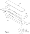
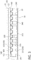
- the transmission module 200 is stacked between the inner layer 23 and the light emitting module 100 (specifically, the LED member 140) and is stacked on an upper side of the inner layer 23 in the embodiments illustrated in FIGS. 2 and 3 .
- the transmission module 200 is disposed between the light emitting module 100 and the optical module 300. That is, in the illustrated embodiment, the transmission module 200, the optical module 300, and the light emitting module 100 are sequentially stacked in that order in a direction from the inside toward the outside. In one embodiment, the transmission module 200 may come into contact with or be coupled to each of the optical module 300 and the inner layer 23. The transmission module 200 may be configured to support the optical module 300.
- the light L transmitted to the transmission module 200 is the light L that has passed through the optical module 300.
- the transmission module 200 includes a first portion 210 and a second portion 220.
- One portion, i.e., the first portion 210, of the transmission module 200 is formed of a light-permeable material or formed to be penetrated.
- the light L heading toward the first portion 210 among light L emitted from the light emitting module 100 may pass through the first portion 210 and be radiated toward the inner layer 23 and the interior space 30.
- another portion, i.e., the second portion 220, of the transmission module 200 is formed of a non-light permeable material.
- the light L heading toward the second portion 220 among the light L emitted from the light emitting module 100 is blocked by the second portion 220.
- the light L emitted from the light emitting module 100 may form an image with a form corresponding to the shapes of the first portion 210 and the second portion 220 of the transmission module 200, on the inner layer 23 or in the interior space 30.
- the first portion 210 of the transmission module 200 i.e., a region through which the light L emitted from the LED member 140 passes, may be formed of a character, a figure, a picture, a motion, or a combination thereof.
- the first portion 210 may be formed of figures of various shapes. Also, as illustrated in FIG. 6B , the first portion 210 may be formed of characters of various shapes.
- the transmission module 200 may selectively transmit the light L emitted from the light emitting module 100 and form predetermined images of various forms. This will be described in detail below.
- the vehicle lighting device 10 includes the optical module 300.
- the light L radiated from the LED member 140 of the light emitting module 100 passes through the optical module 300. Due to the form, properties, or the like of the optical module 300, the light L that has passed through the optical module 300 advances while being refracted in various forms. Accordingly, images of various forms may be formed on the inner layer 23 or in the interior space 30.
- the optical module 300 is disposed between the light emitting module 100 and the transmission module 200. In the illustrated embodiment, the optical module 300 is disposed above the transmission module 200 and below the light emitting module 100. In one embodiment, the optical module 300 may be supported by the transmission module 200 and support the light emitting module 100.
- the optical module 300 may be formed to have a size that corresponds to the size of the inner layer 23 and may be provided as a single optical module 300. In another embodiment, the optical module 300 may be formed to have a size that is smaller than the size of the inner layer 23 and may be provided as a plurality of optical modules 300. In this embodiment, the plurality of optical modules 300 may be disposed to correspond to the shapes and arrangement manner of the inner layer 23 and the light emitting module 100 and the transmission module 200 that cover the inner layer 23. That is, in this embodiment, the optical module 300 may be provided to be modular.
- the optical module 300 includes the optical body 310, an optical hole 320, the optic part 330, and a refractive member 340.
- the optical body 310 forms a body of the optical module 300.
- the optical body 310 is disposed between the light emitting module 100 and the transmission module 200 and disposed on a path along which the light L radiated from the light emitting module 100 is transmitted to advance toward the transmission module 200.
- the optical body 310 may extend in a direction identical to the direction in which the substrate member 110 or the transmission module 200 extends.
- the optical body 310 is formed in the shape of a plate whose length in the left-right direction is longer than the length in the front-rear direction and whose thickness is in the up-down direction.
- the optical body 310 may be formed of a light-permeable material. Accordingly, the light L radiated from the light emitting module 100 may be transmitted through the optical body 310 and advance toward the optic part 330 or the transmission module 200.
- the light L radiated from the first LED member 141 may, while advancing in the up-down direction, be transmitted through the optical body 310 and advance toward the transmission module 200.
- the light L radiated from the second LED member 142 may advance in the horizontal direction or advance with a predetermined slope with respect to the horizontal direction and may be transmitted through the optical body 310 to advance toward the transmission module 200.
- the optical body 310 accommodates the LED member 140, the circuit element member 130, or the optic part 330.
- the optical body 310 may be formed of a soft material or hard material to prevent protrusion of the LED member 140, circuit element member 130, or optic part 330 accommodated therein, i.e., protrusion of the optical body 310 in the thickness direction thereof.
- the optical body 310 also serves to protect the circuit element member 130 or the LED member 140.
- the first LED member 141 is disposed on one surface of the optical body 310 that faces the substrate member 110, an upper surface of the optical body 310 in the illustrated embodiment.
- the second LED members 142 are disposed on end surfaces of the optical body 310 in a longitudinal direction thereof, the left side surface and the right side surface of the optical body 310 in the illustrated embodiment.
- the end surfaces on which the second LED members 142 are disposed may be defined as edge surfaces 311. As described above, the edge surfaces 311 form a portion of an outer side surface of the optical body 310.
- a second optic part 332 of the optic part 330 may be disposed on a portion of the one surface of the optical body 310, i.e., the upper surface thereof, where the optical hole 320 is not formed.
- the light L radiated from the first LED member 141 or the second LED member 142 may be refracted while passing through the second optic part 332 and form images of various forms.
- the optical hole 320 is formed inside the optical body 310.
- the optical hole 320 is formed on one surface of the optical body 310 that faces the substrate member 110, the upper surface of the optical body 310 in the illustrated embodiment.
- the optical hole 320 may be formed to be recessed in or penetrate through the one surface of the optical body 310. That is, the optical hole 320 may be formed as a groove having a predetermined depth or formed to be penetrated in the thickness direction of the optical body 310.
- the optical hole 320 is formed to extend in the thickness direction of the optical body 310, the up-down direction in the illustrated embodiment.
- the first LED member 141 or the circuit element member 130 electrically conducted to the first LED member 141 is accommodated in one side of the optical hole 320, which is an upper side of the optical hole 320 in the illustrated embodiment, that faces the substrate member 110 in an extending direction of the optical hole 320.
- the first LED member 141 may irradiate light toward the transmission module 200 or the inner layer 23 in a state of being accommodated in the optical hole 320.
- the optic part 330 is accommodated in the other side of the optical hole 320, which is a lower side of the optical hole 320 in the illustrated embodiment, that faces the transmission module 200 or the inner layer 23 in the extending direction of the optical hole 320.
- the light L radiated from the first LED member 141 or the second LED member 142 may pass through the optic part 330 and then advance toward the inner layer 23.
- the optical hole 320 may be provided as a plurality of optical holes 320.
- the plurality of optical holes 320 may be disposed apart from each other in an extending direction of the optical body 310. In one embodiment, the plurality of optical holes 320 may be disposed apart from each other in a width direction or breadth direction of the optical body 310.
- the plurality of optical holes 320 may be formed to have different shapes. That is, some of the plurality of optical holes 320 may be formed to be recessed while the rest of the plurality of optical holes 320 are formed to be penetrated. Either is fine as long as the optical hole 320 is able to accommodate the first LED member 141 or the circuit element member 130.
- the optic part 330 refracts the light L radiated from the LED member 140.
- the light L that has passed through the optic part 330 is refracted in various forms and extends toward the inner layer 23 so that images of various forms may be formed.
- the optic part 330 may be formed of a light-permeable material. Also, the optic part 330 may be formed of any other material and shape that allow the optic part 330 to refract the light L transmitted thereto.
- the optic part 330 may be provided as a plurality of optic parts 330. Each of the plurality of optic parts 330 may be disposed at the optical body 310 or the optical hole 320 and may be configured to refract the light L radiated from the first LED member 141 or the second LED member 142.
- the optic part 330 includes a first optic part 331 accommodated in the optical hole 320 and the second optic part 332 disposed at the optical body 310.
- the first optic part 331 is accommodated in the optical hole 320 and configured to refract the light L radiated from the first LED member 141 or the second LED member 142.
- the first optic part 331 is disposed adjacent to the transmission module 200 or the inner layer 23. In the illustrated embodiment, the first optic part 331 is disposed at a lower portion of the optical hole 320.
- the first optic part 331 may be accommodated in a refractive frame 341 and formed as the refractive member 340. That is, as will be described below, the first optic part 331 may be accommodated in the refractive frame 341 to configure the refractive member 340 and then be accommodated in the optical hole 320.
- the first optic part 331 may be directly provided at the other surface of the optical body 310, i.e., the lower surface of the optical body 310, that faces the transmission module 200 or the inner layer 23.
- the first optic part 331 may be provided as a plurality of first optic parts 331.
- the plurality of first optic parts 331 may be formed to have different shapes. Accordingly, light L passing through any one of the plurality of first optic parts 331 may be refracted differently from light L passing through another one of the plurality of first optic parts 331. Consequently, the rays of light L passing through the plurality of first optic parts 331 may form different images.
- the plurality of first optic parts 331 may be disposed in various forms. As illustrated in FIG. 3 , some of the plurality of first optic parts 331 may be accommodated in the refractive frame 341 and accommodated in the optical hole 320. The rest of the plurality of first optic parts 331 may be directly provided at the other surface of the optical body 310, i.e., the lower surface of the optical body 310.
- Some of the plurality of first optic parts 331 may be disposed apart from each other. Also, the rest of the plurality of first optic parts 331 may be consecutively arranged with each other.
- the second optic part 332 is disposed at the optical body 310 and configured to refract the light L radiated from the first LED member 141 or the second LED member 142.
- the second optic part 332 is disposed on a portion of the one surface of the optical body 310, i.e., the upper surface of the optical body 310, where the optical hole 320 is not formed.
- the second optic part 332 may be provided as a plurality of second optic parts 332.
- the plurality of second optic parts 332 may be formed to have different shapes. Accordingly, light L passing through any one of the plurality of second optic parts 332 may be refracted differently from light L passing through another one of the plurality of second optic parts 332. Consequently, the rays of light L passing through the plurality of second optic parts 332 may form different images.
- the plurality of second optic parts 332 may be disposed in various forms. As illustrated in FIG. 3 , some of the plurality of second optic parts 332 may be consecutively arranged between the optical holes 320 adjacent to each other. As an alternative, the plurality of second optic parts 332 may be disposed apart from each other.
- the refractive member 340 is configured to include the first optic part 331 accommodated in the optical hole 320 among the first optic parts 331 and the refractive frame 341 configured to support the first optic part 331 accommodated in the optical hole 320.
- the refractive member 340 is configured to refract the light L radiated from the first LED member 141 or the second LED member 142.
- the refractive member 340 may be provided as a plurality of refractive members 340.
- the plurality of refractive members 340 may be configured to include one or more first optic parts 331. That is, in the embodiment illustrated in FIG. 2 , each refractive member 340 accommodates a single first optic part 331. In the embodiment illustrated in FIG. 3 , some of the refractive members 340 accommodate a plurality of first optic parts 331.
- the plurality of refractive members 340 are each accommodated in one of the plurality of optical holes 320.
- the first LED member 141 accommodated in the optical hole 320 is disposed at an outer side of the refractive member 340 accommodated in the optical hole 320, that is, an upper side of the refractive member 340 in the illustrated embodiment.
- the refractive member 340 includes the refractive frame 341.
- the refractive frame 341 has a space formed therein to accommodate the first optic part 331.
- the refractive frame 341 is formed of a light-permeable material to allow the light L radiated from the first LED member 141 or the second LED member 142 to advance toward the first optic part 331 accommodated therein.
- the refractive frame 341 may be formed in a shape that corresponds to the shape of the optical hole 320.
- the refractive frame 341 is formed in the shape of a quadrangular column. Accordingly, arbitrary shaking of the refractive frame 341 inserted into the optical hole 320 and the first optic part 331 accommodated in the refractive frame 341 is prevented, and thus a predetermined image may be stably formed.
- the above-described vehicle lighting device 10 may be coupled to the frame 20 of the vehicle 1 and irradiate the interior space 30 with the light L to form images of various forms. Also, the vehicle lighting device 10 may radiate the light L of various forms so that various images are formed in the interior space 30.
- a control signal for controlling the light emitting module 100 so that a predetermined image is formed may be generated or changed by a manufacturer of the vehicle 1 or a manufacturer of the vehicle lighting device 10.
- the control signal may be generated or changed by a user of the vehicle 1 or vehicle lighting device 10.
- the light L radiated from the LED member 140 may, after being refracted while passing through the optical module 300, advance toward the inner layer 23 or the interior space 30. Accordingly, the vehicle lighting device 10 according to an embodiment of the present invention may form images of various forms such as point luminescence, plane luminescence, and luminescence due to an optical member.
- FIG. 8 an embodiment in which an image in the form of a star cluster is formed by the vehicle lighting device 10 according to an embodiment of the present invention is illustrated.
- some of the plurality of LED members 140 are turned on or blink, and the rest of the plurality of LED members 140 are turned off.
- the LED members 140 that are turned on or blink and the LED members 140 that are turned off may be randomly selected.
- color, brightness, saturation, luminous intensity, illumination, luminance, an angle of irradiation, blinking, etc. of light L emitted from the LED members 140 that are turned on or blink may be controlled independently from each other. Accordingly, images formed by the light L emitted from the LED members 140 may also have various forms, and thus the sense of realism may be improved.
- FIG. 9 an embodiment in which images in the form of various figures are formed by the vehicle lighting device 10 according to an embodiment of the present invention is illustrated.
- a triangular image is formed at the upper left side
- a star-shaped image is formed at the center
- a circular image is formed at the lower right side.
- some of the plurality of LED members 140 are turned on, and the rest of the plurality of LED members 140 are turned off.
- the LED members 140 that are turned on and the LED members 140 that are turned off may be determined based on the figures.
- color, brightness, saturation, luminous intensity, illumination, luminance, an angle of irradiation, blinking, etc. of light L emitted from the LED members 140 that are turned on may be controlled independently from each other. Accordingly, images formed by the light L emitted from the LED members 140 may also have various forms, and thus the occupants' satisfaction may be increased.
- FIG. 10 an embodiment in which an image in the form of motion is formed by the vehicle lighting device 10 according to an embodiment of the present invention is illustrated.
- a human body image formed to be skewed to the left moves to the right as time passes (see FIG. 10B ).
- the form of the image also changes from a state in which both arms are raised to a state in which both arms are lowered. In this way, an image in the form of motion may be expressed.
- FIG. 11 another embodiment in which an image in the form of motion is formed by the vehicle lighting device 10 according to an embodiment of the present invention is illustrated.
- images in the form of characters such as "LOVE” at an upper side and “HAPPY” at a lower side, are formed on the frame 20 (that is, the inner layer 23).
- images in the form of different characters such as "GOOD” at the upper side and “LUCK” at the lower side, are formed on the frame 20 as time passes.
- the LED members 140 that are turned on and the LED members 140 that are turned off may be determined based on predetermined images to be expressed.
- the LED members 140 that are turned on and the LED members 140 that are turned off among the plurality of LED members 140 may be changed. Consequently, images formed by the light L emitted from the plurality of LED members 140 may be changed over time.
- the form of images formed on the inner layer 23 or in the interior space 30 changes over time, the occupant's boredom may be reduced even when the vehicle 1 is driven for a long time.
- FIG. 12 an example in which an image in the form of nebulae is formed by the vehicle lighting device 10 according to an embodiment of the present invention is illustrated.
- the inner layer 23 on which the image is formed may be divided into a first region A1 and a second region A2.
- images are formed by the light L that is radiated from the first LED member 141 or the second LED member 142 and transmitted through the optical body 310 and the transmission module 200. That is, the images formed in the first region A1 may be defined as images in the form of plane luminescence.
- images are formed by the light L that is radiated from the first LED member 141 or the second LED member 142 and transmitted through the transmission module 200 or the optic part 330.
- an image formed by the light L that has passed through only the transmission module 200 may be defined as an image in the form of point luminescence.
- an image formed by the light L that has been transmitted through the optic part 330 may be defined as luminescence due to the optical member.
- the images formed in the first region A1 may also be formed by the light L passing through the optic part 330.
- the brightness, shape, position, etc. may be formed to be different for the images formed in the form of plane luminescence, point luminescence, or luminescence due to the optical member.
- the vehicle lighting device 10 may form an image in the form of plane luminescence in a portion of the inner layer 23 or the interior space 30, may form an image in the form of point luminescence in another portion thereof, and may form an image in the form of luminescence due to the optical member in still another portion thereof.
- various images may be formed on the inner layer 23 or in the interior space 30 by luminescence in various forms, and thus comfort and satisfaction of a user may be improved.
- a vehicle lighting device and a vehicle including the same allow effective application of the vehicle lighting device according to the shape of the vehicle.
- the vehicle lighting device and vehicle including the same allow images of various forms to be effectively formed.
- the vehicle lighting device and vehicle including the same allow images of various forms to be formed in a space inside the vehicle.
- the vehicle lighting device and vehicle including the same allow prevention of damage to a component for emitting light.
- the vehicle lighting device and vehicle including the same allow an exterior to be aesthetically pleasing.
- the invention relates to the following preferred embodiments:
Landscapes
- Engineering & Computer Science (AREA)
- Mechanical Engineering (AREA)
- Physics & Mathematics (AREA)
- Theoretical Computer Science (AREA)
- General Physics & Mathematics (AREA)
- General Engineering & Computer Science (AREA)
- Business, Economics & Management (AREA)
- Marketing (AREA)
- Accounting & Taxation (AREA)
- Microelectronics & Electronic Packaging (AREA)
- Computer Hardware Design (AREA)
- Textile Engineering (AREA)
- Arrangements Of Lighting Devices For Vehicle Interiors, Mounting And Supporting Thereof, Circuits Therefore (AREA)
Abstract
A vehicle lighting device is disclosed. The vehicle lighting device according to one aspect of the present invention, which is a vehicle lighting device irradiating an interior space of a vehicle with light, includes: a light emitting module configured to irradiate the interior space with light transmitted through an inner layer surrounding the interior space; an optical module disposed between the light emitting module and the inner layer so that the light radiated from the light emitting module is transmitted therethrough; and a transmission module which is disposed between the optical module and the inner layer and includes one portion through which the light emitted from the light emitting module is transmitted and another portion configured to block the emitted light, wherein the light emitting module includes a light emitting diode (LED) member electrically conducted to the outside to emit the light according to a control signal and an applied voltage transmitted thereto, the optical module includes an optical body which is formed of a light-permeable material and disposed to cover the inner layer and an optical hole which is formed to be recessed in or penetrate through the inside of the optical body to form a space in a thickness direction thereof, and the LED member includes a first LED member which is accommodated in the optical hole and configured to irradiate the inner layer with light and a second LED member which is disposed on an edge surface of the optical body and configured to irradiate the inner layer with light transmitted through the inside of the optical body.
Description
- This application claims priority to and the benefit of
Korean Patent Application No. 2021-0060268, filed on May 10, 2021 Korean Patent Application No. 2022-0036022, filed on March 23, 2022 - The present invention relates to a vehicle lighting device and a vehicle including the same, and more particularly, to a vehicle lighting device, which is capable of irradiating the inside of a vehicle with light and forming images of various forms while disposed in the vehicle, and a vehicle including the same.
- In recent years, with improvements in standard of living and the increase in the importance of leisure activities, the number of people traveling away from their main living spaces has increased. For a more convenient and enjoyable trip, people tend to use private vehicles rather than public transportation.
- In addition, as is well known through mass media and the like, so-called "auto-camping," in which people stay inside a vehicle instead of staying in a traditional type of accommodation, has gained sensational popularity. That is, the time people spend in the spaces inside vehicles has increased as compared to the past, and demands regarding the environment inside the vehicle, i.e., the interior, have also increased.
- Accordingly, vehicle manufacturers have made various attempts to transform the space inside a vehicle into a space where people can feel comfort and enjoyment, not just a space to stay while moving.
- Examples of these various attempts include improving the interior lighting with a mood lamp. In the past, generally, a room lamp or the like was used to irradiate an interior space with light to allow objects to be identified or simple tasks to be performed. However, in recent years, with the increase in the time people spend in interior spaces of vehicles as described above, demands for lighting have also diversified.
- However, it is not easy to provide various types of lighting inside a vehicle. Vehicles are subject to many restrictions on their physical and electrical structure due to safety issues. For example, the interior space of a vehicle should be surrounded by a soft protective material to prevent injury to occupants in the event of a collision.
- Further, in order to form various types of lighting in the interior space of a vehicle, various devices such as a large number of lamps and a wiring structure, a power source, etc. for supplying power to the lamps are required. Due to these limitations, it is difficult to secure diversity in interior lighting provided in a vehicle.
- Accordingly, techniques for addressing the above problems have been introduced.
-
Korean Patent Registration No. 10-1684122 - However, the headlining hidden lighting device disclosed in the above related art document has a limitation that it occupies an excessive amount of space. That is, the headlining hidden lighting device disclosed in the above related art document has a structure in which a printed circuit board (PCB) for its control is also mounted on the headlining, and there is concern that the thickness of the headlining may be increased. Accordingly, when an occupant is tall, the occupant may feel discomfort due to the occupant's head coming into contact with the headlining.
- Even when the PCB is accommodated while the height of the headlining is maintained, there is still concern that the headlining hidden lighting device may occupy an excessive amount of space between the upper side of the headlining and an outer frame.
- In addition, because a polyimide film material for typical flexible printed circuit boards (FPCBs) having flexibility that is disclosed in the above related art document includes a conductive thin film, a manufacturing process for configuring a circuit pattern is difficult and complicated, and heat forming is difficult, which makes it difficult to maintain and implement various designs and the shapes of corners with small curvatures.
-
Korean Patent Registration No. 10-1519757 - However, it is difficult to implement various designs using the vehicle mood lamp and lighting method using the same disclosed in the above related art document. That is, although the vehicle mood lamp disclosed in the above related art document is able to change its color, no method of changing an image formed by light without changing the shape of polyurethane foam supporting a light source is proposed.
-
- (Patent Document 0001)
Korean Patent Registration No. 10-1684122 (Date of Registration: December 8, 2016 - (Patent Document 0002)
Korean Patent Registration No. 10-1519757 (Date of Registration: May 12, 2015 - The present invention is directed to providing a vehicle lighting device which has a structure that can be effectively applied according to the shape of a vehicle, and a vehicle including the same.
- The present invention is also directed to providing a vehicle lighting device which has a structure capable of effectively forming images of various forms, and a vehicle including the same.
- The present invention is also directed to providing a vehicle lighting device which has a structure capable of forming images of various forms in a space inside a vehicle, and a vehicle including the same.
- The present invention is also directed to providing a vehicle lighting device which has a structure capable of preventing damage to a component for emitting light, and a vehicle including the same.
- The present invention is also directed to providing a vehicle lighting device which has a structure with an aesthetically pleasing exterior, and a vehicle including the same.
- Objectives of the present invention are not limited to those mentioned above, and other unmentioned objectives should be clearly understood by those of ordinary skill in the art to which the present invention pertains from the description below.
- One aspect of the present invention provides a vehicle lighting device irradiating an interior space of a vehicle with light, the vehicle lighting device including: a light emitting module configured to irradiate the interior space with light transmitted through an inner layer surrounding the interior space; an optical module disposed between the light emitting module and the inner layer so that the light radiated from the light emitting module is transmitted therethrough; and a transmission module which is disposed between the optical module and the inner layer and includes one portion through which the light emitted from the light emitting module is transmitted and another portion configured to block the emitted light, wherein the light emitting module includes a light emitting diode (LED) member electrically conducted to the outside to emit the light according to a control signal and an applied voltage transmitted thereto, the optical module includes an optical body which is formed of a light-permeable material and disposed to cover the inner layer and an optical hole which is formed to be recessed in or penetrate through the inside of the optical body to form a space in a thickness direction thereof, and the LED member includes a first LED member which is accommodated in the optical hole and configured to irradiate the inner layer with light and a second LED member which is disposed on an edge surface of the optical body and configured to irradiate the inner layer with light transmitted through the inside of the optical body.
- Here, a portion of the light emitted from the LED member may be transmitted due to the one portion of the transmission module and another portion of the light emitted from the LED member may be blocked by the other portion of the transmission module, thus creating a mood lighting atmosphere.
- Also, the optical hole may, in a thickness direction of the optical module, accommodate the first LED member or a circuit element member electrically conducted to the first LED member.
- Here, the circuit element member may be provided as a plurality of circuit element members, and the plurality of circuit element members may be configured to control the LED member according to the applied voltage and the control signal transmitted thereto.
- Also, the optical hole may be provided as a plurality of optical holes, and the plurality of optical holes may be disposed to be spaced apart from each other in a width direction of the optical body.
- Here, the second LED member may be provided as a plurality of second LED members, and the plurality of second LED members may each be disposed on one edge surface of the optical body.
- The optical module may include a refractive member which is inserted into the optical hole and includes an optic part configured to refract the light radiated from the first LED member accommodated in the optical hole.
- Here, the optical body may be formed of a soft material or a hard material to accommodate any one or more of the LED member, the circuit element member electrically conducted to the LED member, and the optic part and prevent protrusion thereof in the thickness direction.
- Also, an optic part configured to refract the light radiated from the first LED member accommodated in the optical hole may be formed at one side surface of the optical body that faces the inner layer.
- Here, the optic part may be provided as a plurality of optic parts, and the plurality of optic parts may be formed to have different shapes.
- Also, the optic part may be provided as a plurality of optic parts, and the plurality of optic parts may be disposed to correspond to the optical hole which is provided as a single optical hole or a plurality of optical holes.
- Here, the light emitting module may be modularized and provided as a plurality of light emitting modules, and the plurality of light emitting modules may be disposed to correspond to the shape of the inner layer.
- Also, the optical module may be modularized and provided as a plurality of optical modules, and the plurality of optical modules may be disposed to correspond to the plurality of light emitting modules.
- Here, the first LED member and the second LED member may be provided as any one or more of an LED, a mini LED, a micro LED, and an LED ink, and the light radiated from the first LED member or the second LED member may have a single color, red, green, and blue (RGB), or a combination thereof.
- Also, rays of light radiated from the first LED member and the second LED member may at least partially overlap on the inner layer or in the interior space to form a predetermined image.
- Also, rays of light independently radiated from the second LED member may at least partially overlap on the inner layer or in the interior space to form a predetermined image.
- Here, the LED member may be provided as a plurality of LED members, the plurality of LED members may be disposed in different regions, any one or more of emission of light, and the direction, luminous intensity, illumination, luminance, and color of the emitted light may be independently controlled for the plurality of LED members, and the light emitted from the plurality of LED members may form an image of a character, a figure, a picture, a motion, or a combination thereof.
- Also, the optical module may include a plurality of optic parts configured to refract the light radiated from the plurality of LED members each inserted into one of the plurality of optical holes, and the plurality of optic parts may be formed to have different shapes so that the light radiated from the plurality of LED members transmit through the plurality of optic parts and from images of different shapes.
- Here, the light emitted from the LED member may sequentially pass through the one portion of the transmission module and the inner layer to form a predetermined image in the interior space.
- Also, the one portion of the transmission module may be formed of a character, a figure, a picture, a motion, or a combination thereof.
- Also, one aspect of the present invention provides a vehicle including: an inner layer surrounding an interior space; and a vehicle lighting device stacked on the inner layer to irradiate the interior space with light, wherein the vehicle lighting device includes a light emitting module which is configured to irradiate the interior space with light transmitted through the inner layer and an optical module which is disposed between the light emitting module and the inner layer so that the light radiated from the light emitting module is transmitted therethrough, the light emitting module includes a first LED member which is configured to irradiate the inner layer with light vertical thereto and a second LED member which is configured to irradiate the inner layer with light horizontal thereto, the optical module includes an optical body which is formed of a light-permeable material and disposed to cover the inner layer and a plurality of optical holes which are formed to penetrate or not penetrate through the inside the optical body in a thickness direction thereof, the first LED member is accommodated in the optical hole and configured to irradiate the inner layer with light, and the second LED member is disposed on an edge surface of the optical body and configured to irradiate the inner layer with light transmitted through the inside of the optical body.
- Here, the optical module may include a plurality of optic parts accommodated in the plurality of optical holes and configured to refract the light radiated from the LED member, and any one or more of the plurality of optic parts may be formed to have a shape different from that of one or more other optic parts.
- Also, the vehicle lighting device may further include a transmission module which is disposed between the optical module and the inner layer and includes one portion through which the light emitted from the LED member is transmitted and another portion configured to block the emitted light.
- Here, the first LED member may be provided as a plurality of first LED members and the plurality of first LED members may each be accommodated in one of the plurality of optical holes, and the second LED member may be provided as a plurality of second LED members and the plurality of second LED members may each be disposed on one edge surface of the optical body.
- Also, the light irradiated by the first LED member and the light irradiated by the second LED member may at least partially overlap on the inner layer or in the interior space to form a predetermined image.
- The above and other objects, features and advantages of the present invention will become more apparent to those of ordinary skill in the art by describing exemplary embodiments thereof in detail with reference to the accompanying drawings, in which:
-
FIG 1 shows a lateral cross-sectional view and an enlarged view of a vehicle including a vehicle lighting device according to an embodiment of the present invention; -
FIG 2 is an exploded perspective view illustrating a configuration of the vehicle lighting device ofFIG 1 ; -
FIG. 3 is a cross-sectional view illustrating the configuration of the vehicle lighting device ofFIG. 1 ; -
FIG. 4 is a conceptual diagram illustrating a light emitting module of the vehicle lighting device according to an embodiment of the present invention; -
FIG. 5 is a block diagram illustrating a configuration of the light emitting module of the vehicle lighting device according to an embodiment of the present invention; -
FIG. 6 is a plan view illustrating a transmission module according to an embodiment of the present invention; -
FIG. 7 is a cross-sectional view illustrating light emitted from the vehicle lighting device ofFIG. 1 ; and -
FIGS. 8 to 12 are conceptual diagrams illustrating operation states of the vehicle lighting device according to an embodiment of the present invention. - Hereinafter, embodiments of the present invention will be described in detail with reference to the accompanying drawings to allow those of ordinary skill in the art to which the present invention pertains to easily practice the present invention. The present invention may be implemented in various different forms and is not limited to the embodiments described herein. In order to clearly describe the present invention, parts unrelated to the description have been omitted from the drawings, and the same or similar elements will be denoted by the same reference numerals throughout the specification.
- Terms used in this specification and the claims should be construed as having meanings and concepts that are consistent with the technical spirit of the present invention according to the principle that the inventor may define terms and concepts to describe his or her invention in the best way, rather than being construed as having general or dictionary meanings and being limited thereto.
- Therefore, embodiments described in this specification and configurations illustrated in the drawings correspond to exemplary embodiments of the present invention and do not represent the entire technical spirit of the present invention. Thus, various equivalents and modifications that may replace the corresponding configurations may be present at the time of filing of this application.
- In the following description, descriptions of some components may be omitted to clarify features of the present invention.
- The term "electrically conducted" used in the following description refers to a state in which one or more members are connected to be able to transmit and receive electricity or electronic signals to and from each other. In one embodiment, electrical conduction may be implemented in a wired form using a lead wire member or the like or implemented in a wireless form using Bluetooth, Wi-Fi, RFID, etc.
- Referring to
FIG. 1 , a state in which avehicle lighting device 10 according to an embodiment of the present invention is disposed in avehicle 1 is illustrated as an example. Thevehicle lighting device 10 may be mounted inside aframe 20 that constitutes an exterior of thevehicle 1. - Specifically, the
frame 20 is formed to surround aninterior space 30, i.e., a space configured to accommodate an occupant or an object, that is formed inside thevehicle 1. In other words, theinterior space 30 is a space formed to be surrounded by theframe 20. - Here, the
vehicle lighting device 10 according to an embodiment of the present invention is configured to be accommodated inside theframe 20 to irradiate theinterior space 30 with light L. To this end, thevehicle lighting device 10 may be coupled to theframe 20, and the light L radiated from thevehicle lighting device 10 may pass through some layers of theframe 20 and extend into theinterior space 30. - The
frame 20 may be formed in any shape that allows theframe 20 to form the exterior of thevehicle 1, surround theinterior space 30, and protect an occupant or an object accommodated in theinterior space 30. In the illustrated embodiment, theframe 20 includes anouter layer 21, amold layer 22, and aninner layer 23. - The
outer layer 21 forms an outer surface of theframe 20. Theouter layer 21 is a portion where theframe 20 is exposed at the outside of thevehicle 1. As is known, theouter layer 21 may be formed of a rigid body and protect theinterior space 30 from impact applied from the outside. - The
mold layer 22 forms an intermediate portion of theframe 20. Themold layer 22 is coupled to each of theouter layer 21 and theinner layer 23. - The
inner layer 23 forms an inner surface of theframe 20. Theinner layer 23 surrounds theinterior space 30. In other words, theinner layer 23 is a portion that is exposed in theinterior space 30 and comes in direct contact with the occupant or object accommodated in theinterior space 30. - Therefore, in order to increase comfort of the occupant accommodated in the
interior space 30, theinner layer 23 may be formed of a fabric material or any other known interior materials. In one embodiment, theinner layer 23 may be formed of a leather material. - In particular, the
inner layer 23 according to an embodiment of the present invention may be formed of a light-permeable material. The light L emitted from thevehicle lighting device 10 may pass through theinner layer 23 and extend into theinterior space 30. - The
inner layer 23 may be formed in a shape that corresponds to the shape of theouter layer 21. That is, with regards to an exterior of atypical vehicle 1, theouter layer 21 is formed to include both a flat surface and a curved surface. Thus, theinner layer 23 may also be formed to include both a flat surface and a curved surface in order to correspond to the shape of theouter layer 21. This may be achieved by characteristics of the above-mentioned materials of theinner layer 23. - The
vehicle lighting device 10 according to an embodiment of the present invention may be configured to be coupled to themold layer 22 and radiate the light L toward theinner layer 23. That is, thevehicle lighting device 10 is disposed between themold layer 22 and theinner layer 23. - Therefore, with regards to the cross-section of the
vehicle 1, theinner layer 23, thevehicle lighting device 10, themold layer 22, and theouter layer 21 are sequentially stacked in that order in a direction from theinterior space 30 toward the outside. - The
frame 20 may be any point forming the exterior and interior of thevehicle 1. In the illustrated embodiment, theframe 20 is a ceiling portion, i.e., a headlining portion, that is disposed at an upper side of thevehicle 1. - As an alternative, the
frame 20 may be any point at least partially surrounding theinterior space 30 of thevehicle 1 that includes a trim, a dashboard, a pillar, a rear portion, a front portion, and the like disposed in thevehicle 1 to form an inner side thereof. - That is, the
vehicle lighting device 10 according to an embodiment of the present invention is not limited to being disposed at the ceiling portion of thevehicle 1 but may be disposed at any point of thevehicle 1, such as a sun visor, a sunroof cover, an assist handle, a door trim, a dashboard, a garnish, a center console, a console box, a seat, a door scuff, a car seat, or a car mat to irradiate theinterior space 30 with the light L. - Hereinafter, a configuration of the
vehicle lighting device 10 according to an embodiment of the present invention will be described in detail with reference toFIGS. 2 to 7 . - The
vehicle lighting device 10 according to an embodiment of the present invention may be disposed inside theframe 20, specifically, between themold layer 22 and theinner layer 23, to radiate the light L that passes through theinner layer 23. The light L radiated by thevehicle lighting device 10 may extend into theinterior space 30 and form images of various forms. - As will be described below, the light L radiated by the
vehicle lighting device 10 according to an embodiment of the present invention may form an image of a character, a figure, a picture, a motion, or a combination thereof. - The formed image may be formed on the
inner layer 23 of theframe 20 and visually recognized by the occupant accommodated in theinterior space 30. Accordingly, comfort and an emotional sense of stability of the occupant accommodated in theinterior space 30 may be improved. This will be described in detail below. - In particular, the
vehicle lighting device 10 according to an embodiment of the present invention may be formed to correspond to the above-described shape of theframe 20, i.e., the shape that includes both a flat surface and a curved surface. Therefore, thevehicle lighting device 10 may be stably coupled to theframe 20, and the volume of theinterior space 30 that is occupied by thevehicle lighting device 10 may be reduced. - In one embodiment, the
vehicle lighting device 10 may be formed in a shape which is the same as the shape of theinner layer 23 and disposed to cover theinner layer 23. In this embodiment, thevehicle lighting device 10 may be provided as a single member and disposed to be stacked on theinner layer 23. - In another embodiment, the
vehicle lighting device 10 may have a shape corresponding to theinner layer 23 but have an area smaller than the area of theinner layer 23. In this embodiment, thevehicle lighting device 10 may be provided as a plurality ofvehicle lighting devices 10, and the plurality ofvehicle lighting devices 10 may be stacked to partially cover theinner layer 23. That is, in this embodiment, thevehicle lighting device 10 may be provided to be modular. - Therefore, it may be said that the
vehicle lighting device 10 at least partially surrounds theinner layer 23 and theinterior space 30 that is surrounded by theinner layer 23. - In the illustrated embodiment, the
vehicle lighting device 10 includes alight emitting module 100, atransmission module 200, and anoptical module 300. - Here, the
transmission module 200 may be selectively included. In other words, thevehicle lighting device 10 may only include thelight emitting module 100 and theoptical module 300 or may further include thetransmission module 200. - Therefore, it should be understood that application of various forms of modifications is possible according to conditions of the
vehicle 1 in which thevehicle lighting device 10 is included. - The
light emitting module 100 is a portion where thevehicle lighting device 10 is coupled to themold layer 22. One surface of thelight emitting module 100 that faces themold layer 22, an upper surface of thelight emitting module 100 in the illustrated embodiment, is coupled to a lower surface of themold layer 22. In other words, theinner layer 23, thelight emitting module 100, and themold layer 22 are sequentially stacked in that order in the direction from theinterior space 30 toward the outside. - Also, the
light emitting module 100 is electrically conducted to the outside to receive an applied voltage and a control signal and emits the light L accordingly. As described above, an image is formed on theinner layer 23 or in theinterior space 30 due to the emitted light L. - The
light emitting module 100 may be formed in a shape that corresponds to the shape of theframe 20. As described above, theframe 20 is formed in the shape of a plate that includes both a flat surface and a curved surface. Accordingly, thelight emitting module 100 may also be formed in the shape of a plate including both a flat surface and a curved surface and may be adhered and coupled to theframe 20. - The
light emitting module 100 may constitute a body of thevehicle lighting device 10. Thelight emitting module 100 may be formed in a shape that corresponds to the shape of themold layer 22 or theinner layer 23 which is coupled to thelight emitting module 100. - As described above, in one embodiment, the
vehicle lighting device 10 may be provided to have an area equal to the area of themold layer 22 or theinner layer 23. In this embodiment, thelight emitting module 100 may be formed to have an area equal to the area of themold layer 22 or theinner layer 23. In this embodiment, a singlelight emitting module 100 may be disposed to surround theinner layer 23 and theinterior space 30 surrounded by theinner layer 23. - Also, in another embodiment, the
vehicle lighting device 10 may be provided to have an area smaller than the area of themold layer 22 or theinner layer 23. In this embodiment, thelight emitting module 100 may be formed to have an area smaller than the area of themold layer 22 or theinner layer 23. In this embodiment, each of a plurality oflight emitting modules 100 may be disposed to partially surround theinner layer 23 and theinterior space 30 surrounded by theinner layer 23. - That is, in this embodiment, the
light emitting module 100 may be modularized and provided as a plurality oflight emitting modules 100, and the plurality oflight emitting modules 100 may be disposed in a direction extending in the shape of theinner layer 23. - In an embodiment illustrated in
FIGS. 2 to 4 , thelight emitting module 100 includes asubstrate member 110, acircuit pattern 120, acircuit element member 130, and a light emitting diode (LED)member 140. - The
substrate member 110 forms a body of thelight emitting module 100. Thesubstrate member 110 is a portion where thelight emitting module 100 is coupled to theframe 20, specifically, themold layer 22. - The
circuit pattern 120 is formed on thesubstrate member 110. In one embodiment, thecircuit pattern 120 may be printed on thesubstrate member 110 by any one or more of printing processes including a plate-making mask, stamping, dispensing, inkjet, laser, gravure, and a pad using a conductive paste. - That is, in this embodiment, the
circuit pattern 120 may be formed on thesubstrate member 110 using a conductive material. - Here, a dielectric region formed using a dielectric material may be formed on the
substrate member 110 or thecircuit pattern 120. - That is, the dielectric region may be formed on the
substrate member 110 or thecircuit pattern 120 by any one or more of printing processes including a plate-making mask, stamping, dispensing, inkjet, laser, gravure, and a pad using a dielectric paste or dielectric adhesive. - Also, the
circuit pattern 120 and the dielectric region formed on thesubstrate member 110 may be formed as a plurality ofcircuit patterns 120 and a plurality of dielectric regions. The plurality ofcircuit patterns 120 and the plurality of dielectric regions may be alternately stacked on thesubstrate member 110. - In one embodiment, the
circuit element member 130 and theLED member 140 may be disposed on the plurality ofcircuit patterns 120 and the plurality of dielectric regions that are alternately stacked. - The plurality of
circuit patterns 120, thecircuit element member 130, and theLED member 140 which are formed on thesubstrate member 110 are coupled and electrically conducted. - In one embodiment, the
circuit element member 130 and theLED member 140 may be applied onto the substrate member or the circuit pattern by any one or more of printing processes including a plate-making mask, stamping, dispensing, inkjet, gravure, and a pad using a conductive adhesive and may be coupled to thecircuit pattern 120 formed on thesubstrate member 110 by a typical bonding process. - That is, in this embodiment, the
circuit element member 130 and theLED member 140 may be coupled and electrically conducted to thecircuit pattern 120 formed on thesubstrate member 110 using a conductive material. - As an alternative, in order to strengthen the adhesion of the
circuit element member 130 and theLED member 140, an adhesive material may be used for coupling of thecircuit element member 130 and theLED member 140 to thecircuit pattern 120 formed on thesubstrate member 110. - That is, the
circuit element member 130 and theLED member 140 may be applied onto thesubstrate member 110 or thecircuit pattern 120 by any one or more of printing processes including a plate-making mask, stamping, dispensing, inkjet, laser, gravure, and a pad using an adhesive and may be coupled to thecircuit pattern 120 formed on thesubstrate member 110 by a typical bonding process to increase element adhesion. - That is, in one embodiment, the
circuit element member 130 and theLED member 140 may be applied onto the circuit pattern by any one or more of printing processes including a plate-making mask, stamping, dispensing, inkjet, laser, gravure, and a pad using an adhesive paste to constitute multiple circuit layers. - The
substrate member 110 may be formed in the shape of a plate. Thecircuit pattern 120 may be formed on one surface of thesubstrate member 110 that faces theinterior space 30, a lower surface of thesubstrate member 110 in the illustrated embodiment, and thecircuit element member 130 is coupled and electrically conducted to thecircuit pattern 120. TheLED member 140 is coupled to the lower surface and electrically conducted to thecircuit pattern 120 and thecircuit element member 130. - The other surface of the
substrate member 110 that is opposite to theinterior space 30, an upper surface of thesubstrate member 110 in the illustrated embodiment, is coupled to themold layer 22. In one embodiment, the other surface of thesubstrate member 110 may be fixed and coupled to themold layer 22. - The
substrate member 110 may be formed of a flexible material. Accordingly, the plate-shapedsubstrate member 110 may be deformed to correspond to the shape of themold layer 22 orinner layer 23. Therefore, it should be understood that thesubstrate member 110 and themold layer 22 may be adhered and coupled to each other. - In one embodiment, the
substrate member 110 may be formed of any one or more of a synthetic resin film, leather, artificial leather, fabric, nonwoven fabric, foam, and felt. - The plate-shaped
substrate member 110 may extend in an arbitrary direction. For example, in an embodiment in which thevehicle lighting device 10 is disposed at the ceiling portion of thevehicle 1, the plate-shapedsubstrate member 110 may extend in the left-right direction and front-rear direction to correspond to the ceiling portion. The shape of thesubstrate member 110 may be changed to correspond to the shape of theframe 20 coupled thereto. - In one embodiment, the plate-shaped
substrate member 110 may be formed to have an area that corresponds to the area of theframe 20. In this embodiment, thelight emitting module 100 may be provided as a singlelight emitting module 100, and asingle substrate member 110 may be configured to cover theentire frame 20. Accordingly, thesingle substrate member 110 may be disposed to cover the entireinner layer 23. - In another embodiment, the plate-shaped
substrate member 110 may be formed to have an area smaller than the area of theframe 20. In this embodiment, thesubstrate member 110 may be provided as a plurality ofsubstrate members 110. Each of the plurality ofsubstrate members 110 may be disposed to at least partially cover theinner layer 23. Accordingly, the plurality ofsubstrate members 110 may be disposed to cover theinner layer 23 together. - That is, in this embodiment, it should be understood that the
light emitting module 100 is provided to be modular. In this embodiment, the plurality ofsubstrate members 110 may be disposed in any form that allows the plurality ofsubstrate members 110 to cover theinner layer 23. In one embodiment, thesubstrate members 110 may be disposed to be parallel in the left-right direction and front-rear direction. - The
circuit pattern 120 is configured to be electrically conducted to the outside to receive an applied voltage and a control signal. The received applied voltage and control signal are transmitted to thecircuit element member 130 and theLED member 140 which are coupled and electrically conducted to thecircuit pattern 120. TheLED member 140 may be operated according to the received applied voltage and control signal and emit the light L in various forms. - The
circuit pattern 120 is formed on thesubstrate member 110. As described above, thecircuit pattern 120 is made of a conductive material and formed on thesubstrate member 110. In one embodiment, thecircuit pattern 120 may be printed on thesubstrate member 110. - The
circuit pattern 120 is coupled and electrically conducted to thecircuit element member 130. The applied voltage and control signal transmitted to thecircuit pattern 120 may be transmitted to thecircuit element member 130. - The
circuit pattern 120 is coupled and electrically conducted to theLED member 140. The applied voltage and control signal transmitted to thecircuit pattern 120 may be transmitted to theLED member 140. - The
circuit element member 130 is configured to control theLED member 140 according to the applied voltage and control signal transmitted to thecircuit pattern 120. Thecircuit element member 130 is coupled to thecircuit pattern 120. Thecircuit element member 130 may be provided as a plurality ofcircuit element members 130 that are electrically conducted to each other. Also, thecircuit element member 130 is electrically conducted to theLED member 140. - The
circuit element member 130 may be provided in any form that allows thecircuit element member 130 to process the received applied voltage and control signal and control theLED member 140 on the basis of the processed applied voltage and control signal. In one embodiment, thecircuit element member 130 may be provided as a driving and control element or the like that includes a capacitor, a diode, and an integrated circuit. - The
circuit element member 130 may be provided as a plurality ofcircuit element members 130. The plurality ofcircuit element members 130 may be electrically conducted to each other and may process the received applied voltage and control signal and control theLED member 140 using the processed applied voltage and control signal. Therefore, it should be understood that the plurality ofcircuit element members 130 may be defined as a "control unit." - In one embodiment, some of the plurality of
circuit element members 130 may be disposed apart from thesubstrate member 110. In other words, some of the plurality ofcircuit element members 130 may be disposed outside thesubstrate member 110. - In this embodiment, some of the plurality of
circuit element members 130 may be coupled to a controller (not illustrated) included in thevehicle 1 or may be provided as a separate controller. - The
LED member 140 radiates the light L for forming an image in theinterior space 30. The light L emitted from theLED member 140 may pass through theinner layer 23 and extend into theinterior space 30. In one embodiment, the light L emitted from theLED member 140 may be formed on theinner layer 23 and form an image or may be directly transmitted to the occupant accommodated in theinterior space 30. - The
LED member 140 may perform dot illumination. Accordingly, the light L emitted from theLED member 140 may also be formed in the shape of a dot. In an embodiment in which theLED member 140 is provided as a plurality ofLED members 140, dots formed by rays of light L emitted from the plurality ofLED members 140 may be consecutively arranged to form a predetermined image. - The
vehicle lighting device 10 according to an embodiment of the present invention includes theoptical module 300 which will be described below. The light radiated from theLED member 140 may be refracted while passing through anoptic part 330 disposed in theoptical module 300 and form images of various forms. Also, the light radiated from theLED member 140 may form an image in the form of a plane by passing through anoptical body 310 disposed in theoptical module 300. - The
LED member 140 is coupled to the formedcircuit pattern 120. In the illustrated embodiment, theLED member 140 is coupled to one surface of thesubstrate member 110 that faces theinner layer 23, that is, the lower surface of thesubstrate member 110. It should be understood that the one surface of thesubstrate member 110 is the same as a surface on which thecircuit pattern 120 is printed and to which thecircuit element member 130 is coupled. - Therefore, the
LED member 140 may protrude toward theinner layer 23 past thesubstrate member 110. Accordingly, the shape of theinner layer 23 may be deformed due to theLED member 140, or theLED member 140 may be damaged due to an external force applied through theinner layer 23. In order to prevent this, theoptical module 300 according to an embodiment of the present invention is configured to accommodate theLED member 140. - The
LED member 140 and thecircuit element member 130 are each coupled and electrically conducted to thecircuit pattern 120. An applied voltage and a control signal necessary for theLED member 140 to be operated may be transmitted from thecircuit pattern 120 and thecircuit element member 130. - The
LED member 140 may be provided in any form that allows theLED member 140 to receive the applied voltage and the control signal and be operated accordingly to radiate the light L. In one embodiment, theLED member 140 may be provided as any one or more of an LED, a mini LED, a micro LED, and an LED ink. - The
LED member 140 may be configured to radiate the light L of any color. In one embodiment, theLED member 140 may be configured to radiate the light L having a single color, red, green, and blue (RGB), or a combination thereof. Accordingly, an image formed by theLED member 140 may be formed to have one or more colors. - The
LED member 140 may be provided as a plurality ofLED members 140. The plurality ofLED members 140 may be disposed at different positions to separately irradiate the light L. - In the illustrated embodiment, the
LED members 140 include afirst LED member 141 which is disposed on one surface of thesubstrate member 110 that faces theinner layer 23, that is, the lower surface of thesubstrate member 110, andsecond LED members 142 which are disposed on end surfaces of theoptical body 310 in an extending direction thereof, that is, a left side surface and a right side surface of theoptical body 310 or an upper side surface and a lower side surface of theoptical body 310. - The
first LED members 141 and thesecond LED members 142 may be controlled independently of each other and may each be configured to radiate the light L. - The
first LED member 141 is disposed in a space formed between thesubstrate member 110 and theinner layer 23. Thefirst LED member 141 is disposed between thecircuit pattern 120 formed on thesubstrate member 110 and theinner layer 23. - In the illustrated embodiment, an upper end portion of the
first LED member 141 is coupled and electrically conducted to thecircuit pattern 120 formed on thesubstrate member 110. A lower end portion of thefirst LED member 141 is disposed adjacent to theinner layer 23. - The
first LED member 141 may be provided as a plurality offirst LED members 141. Any one or more of emission of the light L, and the direction, illumination, luminous intensity, luminance, and color of the emitted light L may be independently controlled for the plurality offirst LED members 141. - Accordingly, the light L emitted from the plurality of
first LED members 141 may form various images. Further, the light L emitted from the plurality offirst LED members 141 may also form an image in the form of motion. - In one embodiment, any one or more of illumination, luminous intensity, and luminance may be higher in the light L radiated from the
LED member 140 disposed in a specific region among the plurality ofLED members 140, as compared to the light L radiated from theLED member 140 disposed in another region. - That is, the
LED member 140 disposed in the specific region may emit the light L that is relatively brighter than the light L emitted from theLED member 140 disposed in another region and may serve as an indoor light, i.e., a room lamp. In this embodiment, since it is not necessary to provide a separate room lamp on the ceiling portion of thevehicle 1, the exterior of theinterior space 30 may become more aesthetically pleasing, and efficiency of tasks for manufacturing thevehicle 1 may be improved. - Some of the plurality of
first LED members 141 may be configured to radiate the light L toward theoptic part 330. That is, the light radiated from some of thefirst LED members 141 may pass through theoptic part 330 and then advance toward theinner layer 23. Accordingly, the light radiated from some of thefirst LED members 141 may form an image in an optic form. - The rest of the plurality of
first LED members 141 may be configured to directly irradiate the light L toward theinner layer 23. That is, the light radiated from the rest of thefirst LED members 141 may pass through theoptical body 310 and advance toward theinner layer 23. Accordingly, the light radiated from the rest of thefirst LED members 141 may form an image in the form of point luminescence. - The plurality of
first LED members 141 may be operated in various forms to form images of various forms in theinterior space 30. This will be described in detail below. - The
second LED member 142 is disposed on each end surface of theoptical body 310 in the extending direction thereof. In other words, thesecond LED members 142 is disposed on an edge surface of theoptical body 310. - The
second LED member 142 may be configured to radiate the light L toward the inside of theoptical body 310. That is, the light radiated from thesecond LED member 142 may pass through theoptical body 310 and then advance toward theinner layer 23. Accordingly, the light radiated from thesecond LED member 142 may form an image in the form of plane luminescence. - The
transmission module 200 selectively transmits the light L emitted from thelight emitting module 100 so that a predetermined image is formed on theinner layer 23 or in theinterior space 30. - The
transmission module 200 is coupled to theinner layer 23. Thetransmission module 200 is stacked between theinner layer 23 and the light emitting module 100 (specifically, the LED member 140) and is stacked on an upper side of theinner layer 23 in the embodiments illustrated inFIGS. 2 and3 . - The
transmission module 200 is disposed between the light emittingmodule 100 and theoptical module 300. That is, in the illustrated embodiment, thetransmission module 200, theoptical module 300, and thelight emitting module 100 are sequentially stacked in that order in a direction from the inside toward the outside. In one embodiment, thetransmission module 200 may come into contact with or be coupled to each of theoptical module 300 and theinner layer 23. Thetransmission module 200 may be configured to support theoptical module 300. - Therefore, it should be understood that the light L transmitted to the
transmission module 200 is the light L that has passed through theoptical module 300. - In the illustrated embodiment, the
transmission module 200 includes afirst portion 210 and asecond portion 220. - One portion, i.e., the
first portion 210, of thetransmission module 200 is formed of a light-permeable material or formed to be penetrated. The light L heading toward thefirst portion 210 among light L emitted from thelight emitting module 100 may pass through thefirst portion 210 and be radiated toward theinner layer 23 and theinterior space 30. - Also, another portion, i.e., the
second portion 220, of thetransmission module 200 is formed of a non-light permeable material. The light L heading toward thesecond portion 220 among the light L emitted from thelight emitting module 100 is blocked by thesecond portion 220. - Accordingly, the light L emitted from the
light emitting module 100, specifically, theLED member 140, may form an image with a form corresponding to the shapes of thefirst portion 210 and thesecond portion 220 of thetransmission module 200, on theinner layer 23 or in theinterior space 30. - The
first portion 210 of thetransmission module 200, i.e., a region through which the light L emitted from theLED member 140 passes, may be formed of a character, a figure, a picture, a motion, or a combination thereof. - Referring to
FIG. 6 , examples of images of various forms that are formed by thefirst portion 210 and thesecond portion 220 of thetransmission module 200 are illustrated. - As illustrated in
FIG. 6A , thefirst portion 210 may be formed of figures of various shapes. Also, as illustrated inFIG. 6B , thefirst portion 210 may be formed of characters of various shapes. - Consequently, the
transmission module 200 may selectively transmit the light L emitted from thelight emitting module 100 and form predetermined images of various forms. This will be described in detail below. - Referring to
FIGS. 2 and3 , thevehicle lighting device 10 according to an embodiment of the present invention includes theoptical module 300. - The light L radiated from the
LED member 140 of thelight emitting module 100 passes through theoptical module 300. Due to the form, properties, or the like of theoptical module 300, the light L that has passed through theoptical module 300 advances while being refracted in various forms. Accordingly, images of various forms may be formed on theinner layer 23 or in theinterior space 30. - The
optical module 300 is disposed between the light emittingmodule 100 and thetransmission module 200. In the illustrated embodiment, theoptical module 300 is disposed above thetransmission module 200 and below thelight emitting module 100. In one embodiment, theoptical module 300 may be supported by thetransmission module 200 and support thelight emitting module 100. - In one embodiment, the
optical module 300 may be formed to have a size that corresponds to the size of theinner layer 23 and may be provided as a singleoptical module 300. In another embodiment, theoptical module 300 may be formed to have a size that is smaller than the size of theinner layer 23 and may be provided as a plurality ofoptical modules 300. In this embodiment, the plurality ofoptical modules 300 may be disposed to correspond to the shapes and arrangement manner of theinner layer 23 and thelight emitting module 100 and thetransmission module 200 that cover theinner layer 23. That is, in this embodiment, theoptical module 300 may be provided to be modular. - In the illustrated embodiment, the
optical module 300 includes theoptical body 310, anoptical hole 320, theoptic part 330, and arefractive member 340. - The
optical body 310 forms a body of theoptical module 300. Theoptical body 310 is disposed between the light emittingmodule 100 and thetransmission module 200 and disposed on a path along which the light L radiated from thelight emitting module 100 is transmitted to advance toward thetransmission module 200. - The
optical body 310 may extend in a direction identical to the direction in which thesubstrate member 110 or thetransmission module 200 extends. In the illustrated embodiment, theoptical body 310 is formed in the shape of a plate whose length in the left-right direction is longer than the length in the front-rear direction and whose thickness is in the up-down direction. - The
optical body 310 may be formed of a light-permeable material. Accordingly, the light L radiated from thelight emitting module 100 may be transmitted through theoptical body 310 and advance toward theoptic part 330 or thetransmission module 200. - Specifically, the light L radiated from the
first LED member 141 may, while advancing in the up-down direction, be transmitted through theoptical body 310 and advance toward thetransmission module 200. Also, the light L radiated from thesecond LED member 142 may advance in the horizontal direction or advance with a predetermined slope with respect to the horizontal direction and may be transmitted through theoptical body 310 to advance toward thetransmission module 200. - Through the
optical hole 320 formed therein, theoptical body 310 accommodates theLED member 140, thecircuit element member 130, or theoptic part 330. Here, theoptical body 310 may be formed of a soft material or hard material to prevent protrusion of theLED member 140,circuit element member 130, oroptic part 330 accommodated therein, i.e., protrusion of theoptical body 310 in the thickness direction thereof. - Therefore, it may be said that the
optical body 310 also serves to protect thecircuit element member 130 or theLED member 140. - The
first LED member 141 is disposed on one surface of theoptical body 310 that faces thesubstrate member 110, an upper surface of theoptical body 310 in the illustrated embodiment. Thesecond LED members 142 are disposed on end surfaces of theoptical body 310 in a longitudinal direction thereof, the left side surface and the right side surface of theoptical body 310 in the illustrated embodiment. - The end surfaces on which the
second LED members 142 are disposed may be defined as edge surfaces 311. As described above, the edge surfaces 311 form a portion of an outer side surface of theoptical body 310. - A second
optic part 332 of theoptic part 330 may be disposed on a portion of the one surface of theoptical body 310, i.e., the upper surface thereof, where theoptical hole 320 is not formed. The light L radiated from thefirst LED member 141 or thesecond LED member 142 may be refracted while passing through the secondoptic part 332 and form images of various forms. - The
optical hole 320 is formed inside theoptical body 310. - The
optical hole 320 is formed on one surface of theoptical body 310 that faces thesubstrate member 110, the upper surface of theoptical body 310 in the illustrated embodiment. Theoptical hole 320 may be formed to be recessed in or penetrate through the one surface of theoptical body 310. That is, theoptical hole 320 may be formed as a groove having a predetermined depth or formed to be penetrated in the thickness direction of theoptical body 310. - The
optical hole 320 is formed to extend in the thickness direction of theoptical body 310, the up-down direction in the illustrated embodiment. - The
first LED member 141 or thecircuit element member 130 electrically conducted to thefirst LED member 141 is accommodated in one side of theoptical hole 320, which is an upper side of theoptical hole 320 in the illustrated embodiment, that faces thesubstrate member 110 in an extending direction of theoptical hole 320. Thefirst LED member 141 may irradiate light toward thetransmission module 200 or theinner layer 23 in a state of being accommodated in theoptical hole 320. - The
optic part 330 is accommodated in the other side of theoptical hole 320, which is a lower side of theoptical hole 320 in the illustrated embodiment, that faces thetransmission module 200 or theinner layer 23 in the extending direction of theoptical hole 320. The light L radiated from thefirst LED member 141 or thesecond LED member 142 may pass through theoptic part 330 and then advance toward theinner layer 23. - The
optical hole 320 may be provided as a plurality ofoptical holes 320. The plurality ofoptical holes 320 may be disposed apart from each other in an extending direction of theoptical body 310. In one embodiment, the plurality ofoptical holes 320 may be disposed apart from each other in a width direction or breadth direction of theoptical body 310. - Here, the plurality of
optical holes 320 may be formed to have different shapes. That is, some of the plurality ofoptical holes 320 may be formed to be recessed while the rest of the plurality ofoptical holes 320 are formed to be penetrated. Either is fine as long as theoptical hole 320 is able to accommodate thefirst LED member 141 or thecircuit element member 130. - The
optic part 330 refracts the light L radiated from theLED member 140. The light L that has passed through theoptic part 330 is refracted in various forms and extends toward theinner layer 23 so that images of various forms may be formed. - The
optic part 330 may be formed of a light-permeable material. Also, theoptic part 330 may be formed of any other material and shape that allow theoptic part 330 to refract the light L transmitted thereto. - The
optic part 330 may be provided as a plurality ofoptic parts 330. Each of the plurality ofoptic parts 330 may be disposed at theoptical body 310 or theoptical hole 320 and may be configured to refract the light L radiated from thefirst LED member 141 or thesecond LED member 142. - In the illustrated embodiment, the
optic part 330 includes a firstoptic part 331 accommodated in theoptical hole 320 and the secondoptic part 332 disposed at theoptical body 310. - The first
optic part 331 is accommodated in theoptical hole 320 and configured to refract the light L radiated from thefirst LED member 141 or thesecond LED member 142. The firstoptic part 331 is disposed adjacent to thetransmission module 200 or theinner layer 23. In the illustrated embodiment, the firstoptic part 331 is disposed at a lower portion of theoptical hole 320. - The first
optic part 331 may be accommodated in arefractive frame 341 and formed as therefractive member 340. That is, as will be described below, the firstoptic part 331 may be accommodated in therefractive frame 341 to configure therefractive member 340 and then be accommodated in theoptical hole 320. - Also, as illustrated in
FIG. 3 , the firstoptic part 331 may be directly provided at the other surface of theoptical body 310, i.e., the lower surface of theoptical body 310, that faces thetransmission module 200 or theinner layer 23. - The first
optic part 331 may be provided as a plurality of firstoptic parts 331. The plurality of firstoptic parts 331 may be formed to have different shapes. Accordingly, light L passing through any one of the plurality of firstoptic parts 331 may be refracted differently from light L passing through another one of the plurality of firstoptic parts 331. Consequently, the rays of light L passing through the plurality of firstoptic parts 331 may form different images. - The plurality of first
optic parts 331 may be disposed in various forms. As illustrated inFIG. 3 , some of the plurality of firstoptic parts 331 may be accommodated in therefractive frame 341 and accommodated in theoptical hole 320. The rest of the plurality of firstoptic parts 331 may be directly provided at the other surface of theoptical body 310, i.e., the lower surface of theoptical body 310. - Some of the plurality of first
optic parts 331 may be disposed apart from each other. Also, the rest of the plurality of firstoptic parts 331 may be consecutively arranged with each other. - The second
optic part 332 is disposed at theoptical body 310 and configured to refract the light L radiated from thefirst LED member 141 or thesecond LED member 142. The secondoptic part 332 is disposed on a portion of the one surface of theoptical body 310, i.e., the upper surface of theoptical body 310, where theoptical hole 320 is not formed. - The second
optic part 332 may be provided as a plurality of secondoptic parts 332. The plurality of secondoptic parts 332 may be formed to have different shapes. Accordingly, light L passing through any one of the plurality of secondoptic parts 332 may be refracted differently from light L passing through another one of the plurality of secondoptic parts 332. Consequently, the rays of light L passing through the plurality of secondoptic parts 332 may form different images. - The plurality of second
optic parts 332 may be disposed in various forms. As illustrated inFIG. 3 , some of the plurality of secondoptic parts 332 may be consecutively arranged between theoptical holes 320 adjacent to each other. As an alternative, the plurality of secondoptic parts 332 may be disposed apart from each other. - The
refractive member 340 is configured to include the firstoptic part 331 accommodated in theoptical hole 320 among the firstoptic parts 331 and therefractive frame 341 configured to support the firstoptic part 331 accommodated in theoptical hole 320. Therefractive member 340 is configured to refract the light L radiated from thefirst LED member 141 or thesecond LED member 142. - The
refractive member 340 may be provided as a plurality ofrefractive members 340. The plurality ofrefractive members 340 may be configured to include one or more firstoptic parts 331. That is, in the embodiment illustrated inFIG. 2 , eachrefractive member 340 accommodates a single firstoptic part 331. In the embodiment illustrated inFIG. 3 , some of therefractive members 340 accommodate a plurality of firstoptic parts 331. - The plurality of
refractive members 340 are each accommodated in one of the plurality ofoptical holes 320. Thefirst LED member 141 accommodated in theoptical hole 320 is disposed at an outer side of therefractive member 340 accommodated in theoptical hole 320, that is, an upper side of therefractive member 340 in the illustrated embodiment. - In the illustrated embodiment, the
refractive member 340 includes therefractive frame 341. - The
refractive frame 341 has a space formed therein to accommodate the firstoptic part 331. Therefractive frame 341 is formed of a light-permeable material to allow the light L radiated from thefirst LED member 141 or thesecond LED member 142 to advance toward the firstoptic part 331 accommodated therein. - The
refractive frame 341 may be formed in a shape that corresponds to the shape of theoptical hole 320. In the illustrated embodiment, like theoptical hole 320, therefractive frame 341 is formed in the shape of a quadrangular column. Accordingly, arbitrary shaking of therefractive frame 341 inserted into theoptical hole 320 and the firstoptic part 331 accommodated in therefractive frame 341 is prevented, and thus a predetermined image may be stably formed. - The above-described
vehicle lighting device 10 according to an embodiment of the present invention may be coupled to theframe 20 of thevehicle 1 and irradiate theinterior space 30 with the light L to form images of various forms. Also, thevehicle lighting device 10 may radiate the light L of various forms so that various images are formed in theinterior space 30. - Here, a control signal for controlling the
light emitting module 100 so that a predetermined image is formed may be generated or changed by a manufacturer of thevehicle 1 or a manufacturer of thevehicle lighting device 10. Alternatively, the control signal may be generated or changed by a user of thevehicle 1 orvehicle lighting device 10. - Also, the light L radiated from the
LED member 140 may, after being refracted while passing through theoptical module 300, advance toward theinner layer 23 or theinterior space 30. Accordingly, thevehicle lighting device 10 according to an embodiment of the present invention may form images of various forms such as point luminescence, plane luminescence, and luminescence due to an optical member. - Hereinafter, examples of various images formed by the
vehicle lighting device 10 according to an embodiment of the present invention will be described with reference toFIGS. 8 to 12 . - Referring to
FIG. 8 , an embodiment in which an image in the form of a star cluster is formed by thevehicle lighting device 10 according to an embodiment of the present invention is illustrated. - In this embodiment, some of the plurality of
LED members 140 are turned on or blink, and the rest of the plurality ofLED members 140 are turned off. Here, theLED members 140 that are turned on or blink and theLED members 140 that are turned off may be randomly selected. - Also, color, brightness, saturation, luminous intensity, illumination, luminance, an angle of irradiation, blinking, etc. of light L emitted from the
LED members 140 that are turned on or blink may be controlled independently from each other. Accordingly, images formed by the light L emitted from theLED members 140 may also have various forms, and thus the sense of realism may be improved. - Referring to
FIG. 9 , an embodiment in which images in the form of various figures are formed by thevehicle lighting device 10 according to an embodiment of the present invention is illustrated. - That is, in the illustrated embodiment, a triangular image is formed at the upper left side, a star-shaped image is formed at the center, and a circular image is formed at the lower right side.
- In this embodiment, some of the plurality of
LED members 140 are turned on, and the rest of the plurality ofLED members 140 are turned off. Here, theLED members 140 that are turned on and theLED members 140 that are turned off may be determined based on the figures. - Also, color, brightness, saturation, luminous intensity, illumination, luminance, an angle of irradiation, blinking, etc. of light L emitted from the
LED members 140 that are turned on may be controlled independently from each other. Accordingly, images formed by the light L emitted from theLED members 140 may also have various forms, and thus the occupants' satisfaction may be increased. - Referring to
FIG. 10 , an embodiment in which an image in the form of motion is formed by thevehicle lighting device 10 according to an embodiment of the present invention is illustrated. - That is, a human body image formed to be skewed to the left (see
FIG. 10A ) moves to the right as time passes (seeFIG. 10B ). Here, the form of the image also changes from a state in which both arms are raised to a state in which both arms are lowered. In this way, an image in the form of motion may be expressed. - Referring to
FIG. 11 , another embodiment in which an image in the form of motion is formed by thevehicle lighting device 10 according to an embodiment of the present invention is illustrated. - That is, referring to
FIG. 11A , images in the form of characters, such as "LOVE" at an upper side and "HAPPY" at a lower side, are formed on the frame 20 (that is, the inner layer 23). Referring toFIG. 11B , images in the form of different characters, such as "GOOD" at the upper side and "LUCK" at the lower side, are formed on theframe 20 as time passes. - Even in this embodiment, as in the embodiment illustrated in
FIG. 10 , some of the plurality ofLED members 140 are turned on, and the rest of the plurality ofLED members 140 are turned off. Here, theLED members 140 that are turned on and theLED members 140 that are turned off may be determined based on predetermined images to be expressed. - Here, as time passes, the
LED members 140 that are turned on and theLED members 140 that are turned off among the plurality ofLED members 140 may be changed. Consequently, images formed by the light L emitted from the plurality ofLED members 140 may be changed over time. - Accordingly, since the form of images formed on the
inner layer 23 or in theinterior space 30 changes over time, the occupant's boredom may be reduced even when thevehicle 1 is driven for a long time. - In the illustrated embodiments, cases where images are changed over time from figure to figure or character to character are illustrated. As an alternative, an image in the form of any one of the above-described characters, figures, and pictures may be changed to an image in the form of any one or more of characters, figures, and pictures to form an image in the form of motion.
- Referring to
FIG. 12 , an example in which an image in the form of nebulae is formed by thevehicle lighting device 10 according to an embodiment of the present invention is illustrated. - Here, the
inner layer 23 on which the image is formed may be divided into a first region A1 and a second region A2. - In the first region A1, images are formed by the light L that is radiated from the
first LED member 141 or thesecond LED member 142 and transmitted through theoptical body 310 and thetransmission module 200. That is, the images formed in the first region A1 may be defined as images in the form of plane luminescence. - In the second region A2, images are formed by the light L that is radiated from the
first LED member 141 or thesecond LED member 142 and transmitted through thetransmission module 200 or theoptic part 330. - Among the images formed in the second region A2, an image formed by the light L that has passed through only the
transmission module 200 may be defined as an image in the form of point luminescence. Also, among the images formed in the second region A2, an image formed by the light L that has been transmitted through theoptic part 330 may be defined as luminescence due to the optical member. - Here, it should be understood that the images formed in the first region A1 may also be formed by the light L passing through the
optic part 330. - Also, the brightness, shape, position, etc. may be formed to be different for the images formed in the form of plane luminescence, point luminescence, or luminescence due to the optical member.
- Therefore, the
vehicle lighting device 10 according to an embodiment of the present invention may form an image in the form of plane luminescence in a portion of theinner layer 23 or theinterior space 30, may form an image in the form of point luminescence in another portion thereof, and may form an image in the form of luminescence due to the optical member in still another portion thereof. - Accordingly, various images may be formed on the
inner layer 23 or in theinterior space 30 by luminescence in various forms, and thus comfort and satisfaction of a user may be improved. - According to the configurations described above, a vehicle lighting device and a vehicle including the same according to an embodiment of the present invention allow effective application of the vehicle lighting device according to the shape of the vehicle.
- Also, according to the configurations described above, the vehicle lighting device and vehicle including the same according to an embodiment of the present invention allow images of various forms to be effectively formed.
- Also, according to the configurations described above, the vehicle lighting device and vehicle including the same according to an embodiment of the present invention allow images of various forms to be formed in a space inside the vehicle.
- Also, according to the configurations described above, the vehicle lighting device and vehicle including the same according to an embodiment of the present invention allow prevention of damage to a component for emitting light.
- In addition, according to the configurations described above, the vehicle lighting device and vehicle including the same according to an embodiment of the present invention allow an exterior to be aesthetically pleasing.
- Advantageous effects of the present invention are not limited to those mentioned above and should be understood as including any effect deducible from the detailed description of the present invention or configurations of the invention described in the appended claims.
- Embodiments of the present invention have been described above, but the spirit of the present invention is not limited by the embodiments proposed herein. Those of ordinary skill in the art who understand the spirit of the present invention may easily propose other embodiments by addition, modification, omission, or the like of components within the scope of the same spirit, but such embodiments also belong to the scope of the spirit of the present invention.
- In particular, the invention relates to the following preferred embodiments:
-
Embodiment 1. A vehicle lighting device irradiating an interior space of a vehicle with light, the vehicle lighting device comprising:- a light emitting module configured to irradiate the interior space with light transmitted through an inner layer surrounding the interior space;
- an optical module disposed between the light emitting module and the inner layer so that the light radiated from the light emitting module is transmitted therethrough; and
- a transmission module which is disposed between the optical module and the inner layer and includes one portion through which the light emitted from the light emitting module is transmitted and another portion configured to block the emitted light,
- wherein the light emitting module includes a light emitting diode (LED) member electrically conducted to the outside to emit the light according to a control signal and an applied voltage transmitted thereto,
- the optical module includes an optical body which is formed of a light-permeable material and disposed to cover the inner layer and an optical hole which is formed to be recessed in or penetrate through the inside of the optical body to form a space in a thickness direction thereof, and
- the LED member includes a first LED member which is accommodated in the optical hole and configured to irradiate the inner layer with light and a second LED member which is disposed on an edge surface of the optical body and configured to irradiate the inner layer with light transmitted through the inside of the optical body.
- Embodiment 2. The vehicle lighting device of
embodiment 1, wherein:- a portion of the light emitted from the LED member is transmitted due to the one portion of the transmission module; and
- another portion of the light emitted from the LED member is blocked by the other portion of the transmission module, thus creating a mood lighting atmosphere.
- Embodiment 3. The vehicle lighting device of
embodiment 1, wherein, in a thickness direction of the optical module, the optical hole accommodates the first LED member or a circuit element member electrically conducted to the first LED member. - Embodiment 4. The vehicle lighting device of embodiment 3, wherein the circuit element member is provided as a plurality of circuit element members, and the plurality of circuit element members are configured to control the LED member according to the applied voltage and the control signal transmitted thereto.
- Embodiment 5. The vehicle lighting device of
embodiment 1, wherein the optical hole is provided as a plurality of optical holes, and the plurality of optical holes are disposed apart from each other in a width direction of the optical body. - Embodiment 6. The vehicle lighting device of
embodiment 1, wherein the second LED member is provided as a plurality of second LED members, and the plurality of second LED members are each disposed on one edge surface of the optical body. - Embodiment 7. The vehicle lighting device of
embodiment 1, wherein the optical module includes a refractive member which is inserted into the optical hole and includes an optic part configured to refract the light radiated from the first LED member accommodated in the optical hole. - Embodiment 8. The vehicle lighting device of embodiment 7, wherein the optical body is formed of a soft material or a hard material to accommodate any one or more of the LED member, the circuit element member electrically conducted to the LED member, and the optic part and prevent protrusion thereof in the thickness direction.
- Embodiment 9. The vehicle lighting device of
embodiment 1, wherein an optic part configured to refract the light radiated from the first LED member accommodated in the optical hole is formed at one side surface of the optical body that faces the inner layer. -
Embodiment 10. The vehicle lighting device of embodiment 7 or 9, wherein the optic part is provided as a plurality of optic parts, and the plurality of optic parts are formed to have different shapes. - Embodiment 11. The vehicle lighting device of embodiment 7 or 9, wherein the optic part is provided as a plurality of optic parts, and the plurality of optic parts are disposed to correspond to the optical hole which is provided as a single optical hole or a plurality of optical holes.
- Embodiment 12. The vehicle lighting device of
embodiment 1, wherein the light emitting module is modularized and provided as a plurality of light emitting modules, and the plurality of light emitting modules are disposed to correspond to the shape of the inner layer. - Embodiment 13. The vehicle lighting device of
embodiment 1, wherein the optical module is modularized and provided as a plurality of optical modules, and the plurality of optical modules are disposed to correspond to the plurality of light emitting modules. - Embodiment 14. The vehicle lighting device of
embodiment 1, wherein:- the first LED member and the second LED member are provided as any one or more of an LED, a mini LED, a micro LED, and an LED ink; and
- the light radiated from the first LED member or the second LED member has a single color, red, green, and blue (RGB), or a combination thereof.
- Embodiment 15. The vehicle lighting device of embodiment 14, wherein rays of light radiated from the first LED member and the second LED member at least partially overlap on the inner layer or in the interior space to form a predetermined image.
- Embodiment 16. The vehicle lighting device of embodiment 14, wherein rays of light independently radiated from the second LED member at least partially overlap on the inner layer or in the interior space to form a predetermined image.
- Embodiment 17. The vehicle lighting device of
embodiment 1, wherein:- the LED member is provided as a plurality of LED members, and the plurality of LED members are disposed in different regions;
- any one or more of emission of light, and the direction, luminous intensity, illumination, luminance, and color of the emitted light are independently controlled for the plurality of LED members; and
- the light emitted from the plurality of LED members forms an image of a character, a figure, a picture, a motion, or a combination thereof.
- Embodiment 18. The vehicle lighting device of embodiment 17, wherein:
- the optical module includes a plurality of optic parts configured to refract the light radiated from the plurality of LED members each inserted into one of the plurality of optical holes; and
- the plurality of optic parts are formed to have different shapes so that the light radiated from the plurality of LED members transmit through the plurality of optic parts and from images of different shapes.
- Embodiment 19. The vehicle lighting device of
embodiment 1, wherein the light emitted from the LED member sequentially passes through the one portion of the transmission module and the inner layer to form a predetermined image in the interior space. -
Embodiment 20. The vehicle lighting device ofembodiment 1, wherein the one portion of the transmission module is formed of a character, a figure, a picture, a motion, or a combination thereof. -
Embodiment 21. A vehicle comprising:- an inner layer surrounding an interior space; and
- a vehicle lighting device stacked on the inner layer to irradiate the interior space with light,
- wherein the vehicle lighting device includes a light emitting module which is configured to irradiate the interior space with light transmitted through the inner layer and an optical module which is disposed between the light emitting module and the inner layer so that the light radiated from the light emitting module is transmitted therethrough,
- the light emitting module includes a first LED member which is configured to irradiate the inner layer with light vertical thereto and a second LED member which is configured to irradiate the inner layer with light horizontal thereto,
- the optical module includes an optical body which is formed of a light-permeable material and disposed to cover the inner layer and a plurality of optical holes which are formed to penetrate or not penetrate through the inside the optical body in a thickness direction thereof,
- the first LED member is accommodated in the optical hole and configured to irradiate the inner layer with light, and
- the second LED member is disposed on an edge surface of the optical body and configured to irradiate the inner layer with light transmitted through the inside of the optical body.
-
Embodiment 22. The vehicle ofembodiment 21, wherein:- the optical module includes a plurality of optic parts accommodated in the plurality of optical holes and configured to refract the light radiated from the LED member; and
- any one or more of the plurality of optic parts are formed to have a shape different from that of one or more other optic parts.
-
Embodiment 23. The vehicle ofembodiment 21, further comprising a transmission module which is disposed between the optical module and the inner layer and includes one portion through which the light emitted from the LED member is transmitted and another portion configured to block the emitted light. - Embodiment 24. The vehicle of
embodiment 21, wherein:- the first LED member is provided as a plurality of first LED members, and the plurality of first LED members are each accommodated in one of the plurality of optical holes; and
- the second LED member is provided as a plurality of second LED members, and the plurality of second LED members are each disposed on one edge surface of the optical body.
- Embodiment 25. The vehicle of
embodiment 21, wherein the light irradiated by the first LED member and the light irradiated by the second LED member at least partially overlap on the inner layer or in the interior space to form a predetermined image.
Claims (15)
- A vehicle lighting device (10) irradiating an interior space (30) of a vehicle (1) with light, the vehicle lighting device (10) comprising:a light emitting module (100) configured to irradiate the interior space (30) with light transmitted through an inner layer (23) surrounding the interior space (30);an optical module (300) disposed between the light emitting module (100) and the inner layer (23) so that the light radiated from the light emitting module (100) is transmitted therethrough; anda transmission module (200) which is disposed between the optical module (300) and the inner layer (23) and includes one portion through which the light emitted from the light emitting module (100) is transmitted and another portion configured to block the emitted light,wherein the light emitting module (100) includes a light emitting diode (LED) member (140) electrically conducted to the outside to emit the light according to a control signal and an applied voltage transmitted thereto,the optical module (300) includes an optical body (310) which is formed of a light-permeable material and disposed to cover the inner layer (23) and an optical hole (320) which is formed to be recessed in or penetrate through the inside of the optical body (310) to form a space in a thickness direction thereof, andthe LED member (140) (140) includes a first LED member (141) which is accommodated in the optical hole (320) and configured to irradiate the inner layer (23) with light and a second LED member (142) which is disposed on an edge surface (311) of the optical body (310) and configured to irradiate the inner layer (23) with light transmitted through the inside of the optical body (310).
- The vehicle lighting device (10) of claim 1, wherein:a portion of the light emitted from the LED member (140) is transmitted due to the one portion of the transmission module (200); andanother portion of the light emitted from the LED member (140) is blocked by the other portion of the transmission module (200), thus creating a mood lighting atmosphere.
- The vehicle lighting device (10) of claim 1, wherein, in a thickness direction of the optical module (300), the optical hole (320) accommodates the first LED member (141) or a circuit element member (130) electrically conducted to the first LED member (141), and
wherein the circuit element member (130) is provided as a plurality of circuit element members (130), and the plurality of circuit element members (130) are configured to control the LED member (140) according to the applied voltage and the control signal transmitted thereto. - The vehicle lighting device (10) of claim 1, wherein the optical hole (320) is provided as a plurality of optical holes (320), and the plurality of optical holes (320) are disposed apart from each other in a width direction of the optical body (310).
- The vehicle lighting device (10) of claim 1, wherein the second LED member (142) is provided as a plurality of second LED members (142), and the plurality of second LED members (142) are each disposed on one edge surface (311) of the optical body (310).
- The vehicle lighting device (10) of claim 1, wherein the optical module (300) includes a refractive member (340) which is inserted into the optical hole (320) and includes an optic part (330) configured to refract the light radiated from the first LED member (141) accommodated in the optical hole (320), and
wherein the optical body (310) is formed of a soft material or a hard material to accommodate any one or more of the LED member (140), the circuit element member (130) electrically conducted to the LED member (140), and the optic part (330) and prevent protrusion thereof in the thickness direction. - The vehicle lighting device (10) of claim 1, wherein an optic part (330) configured to refract the light radiated from the first LED member (141) accommodated in the optical hole (320) is formed at one side surface of the optical body (310) that faces the inner layer (23).
- The vehicle lighting device (10) of claim 6 or 7, wherein the optic part (330) is provided as a plurality of optic parts (330), and the plurality of optic parts (330) are formed to have different shapes.
- The vehicle lighting device (10) of claim 6 or 7, wherein the optic part (330) is provided as a plurality of optic parts (330), and the plurality of optic parts (330) are disposed to correspond to the optical hole (320) which is provided as a single optical hole (320) or a plurality of optical holes (320).
- The vehicle lighting device (10) of claim 1, wherein the light emitting module (100) is modularized and provided as a plurality of light emitting modules (100), and the plurality of light emitting modules (100) are disposed to correspond to the shape of the inner layer (23).
- The vehicle lighting device (10) of claim 1, wherein the optical module (300) is modularized and provided as a plurality of optical modules (300), and the plurality of optical modules (300) are disposed to correspond to the plurality of light emitting modules (100).
- The vehicle lighting device (10) of claim 1, wherein:the first LED member (141) and the second LED member (142) are provided as any one or more of an LED, a mini LED, a micro LED, and an LED ink; andthe light radiated from the first LED member (141) or the second LED member (142) has a single color, red, green, and blue (RGB), or a combination thereof, andwherein rays of light radiated from the first LED member (141) and the second LED member (142) at least partially overlap on the inner layer (23) or in the interior space (30) to form a predetermined image.
- The vehicle lighting device (10) of claim 1, wherein:the LED member (140) is provided as a plurality of LED members (140), and the plurality of LED members (140) are disposed in different regions;any one or more of emission of light, and the direction, luminous intensity, illumination, luminance, and color of the emitted light are independently controlled for the plurality of LED members (140); andthe light emitted from the plurality of LED members (140) forms an image of a character, a figure, a picture, a motion, or a combination thereof, andwherein:the optical module (300) includes a plurality of optic parts (330) configured to refract the light radiated from the plurality of LED members (140) each inserted into one of the plurality of optical holes (320); andthe plurality of optic parts (330) are formed to have different shapes so that the light radiated from the plurality of LED members (140) transmit through the plurality of optic parts (330) and from images of different shapes.
- The vehicle lighting device (10) of claim 1, wherein the light emitted from the LED member (140) sequentially passes through the one portion of the transmission module (200) and the inner layer (23) to form a predetermined image in the interior space (30).
- The vehicle lighting device (10) of claim 1, wherein the one portion of the transmission module (200) is formed of a character, a figure, a picture, a motion, or a combination thereof.
Applications Claiming Priority (2)
| Application Number | Priority Date | Filing Date | Title |
|---|---|---|---|
| KR20210060268 | 2021-05-10 | ||
| KR1020220036022A KR102499991B1 (en) | 2021-05-10 | 2022-03-23 | Vehicle lighting fixtures and vehicle include the same |
Publications (1)
| Publication Number | Publication Date |
|---|---|
| EP4088972A1 true EP4088972A1 (en) | 2022-11-16 |
Family
ID=81074260
Family Applications (1)
| Application Number | Title | Priority Date | Filing Date |
|---|---|---|---|
| EP22165504.6A Withdrawn EP4088972A1 (en) | 2021-05-10 | 2022-03-30 | Vehicle lighting device |
Country Status (2)
| Country | Link |
|---|---|
| US (1) | US20220355731A1 (en) |
| EP (1) | EP4088972A1 (en) |
Families Citing this family (1)
| Publication number | Priority date | Publication date | Assignee | Title |
|---|---|---|---|---|
| KR20260009032A (en) * | 2024-07-10 | 2026-01-19 | 현대모비스 주식회사 | Optical device, method of manufacturing the same, and vehicle equipped with the optical device |
Citations (9)
| Publication number | Priority date | Publication date | Assignee | Title |
|---|---|---|---|---|
| WO2006057531A1 (en) * | 2004-11-26 | 2006-06-01 | Kim, Sean | Light emitting mat for vehicles |
| EP2572936A1 (en) * | 2011-09-21 | 2013-03-27 | Grupo Antolin-Ingenieria, S.A. | Trim part for automobile with integrated lighting device and process for manufacturing it |
| US20140265934A1 (en) * | 2013-03-15 | 2014-09-18 | Federal-Mogul Corporation | Vehicle interior lighting |
| KR101519757B1 (en) | 2013-12-19 | 2015-05-12 | 현대자동차주식회사 | A mood lamp of the vehicle and a lighting method using this |
| US20150307033A1 (en) * | 2014-04-29 | 2015-10-29 | Global Ip Holdings, Llc | Vehicle trim part having a layered, decorative finish and configured to form a light pattern at the front of the part |
| KR101684122B1 (en) | 2015-05-29 | 2016-12-08 | 현대자동차주식회사 | Hidden lighting sysrem for head lining |
| DE102018102331A1 (en) * | 2018-02-02 | 2019-08-08 | Dr. Ing. H.C. F. Porsche Aktiengesellschaft | Interior lighting device for a motor vehicle |
| US20200139814A1 (en) * | 2016-07-11 | 2020-05-07 | Shanghai Yanfeng Jinqiao Automotive Trim Systems Co. Ltd. | Vehicle interior component |
| US10672327B1 (en) * | 2019-01-02 | 2020-06-02 | Jvis-Usa, Llc | Low-profile display assembly for a vehicle and configured to display computer-generated imagery at the front of the assembly |
Family Cites Families (12)
| Publication number | Priority date | Publication date | Assignee | Title |
|---|---|---|---|---|
| US7857457B2 (en) * | 2006-09-29 | 2010-12-28 | 3M Innovative Properties Company | Fluorescent volume light source having multiple fluorescent species |
| US8820994B2 (en) * | 2011-07-28 | 2014-09-02 | Visteon Global Technologies, Inc. | Vehicle indicator display, and method of forming |
| EP2902694B1 (en) * | 2012-09-27 | 2020-11-04 | LG Innotek Co., Ltd. | Illuminating device and vehicle lamp comprising same |
| DE102013211867A1 (en) * | 2013-06-21 | 2014-12-24 | Hella Kgaa Hueck & Co. | lighting device |
| US9764686B2 (en) * | 2013-11-21 | 2017-09-19 | Ford Global Technologies, Llc | Light-producing assembly for a vehicle |
| US10099606B2 (en) * | 2016-06-02 | 2018-10-16 | Ford Global Technologies, Llc | Dome light assemblies and units that produce natural and courtesy light patterns |
| US9855888B1 (en) * | 2016-06-29 | 2018-01-02 | Ford Global Technologies, Llc | Photoluminescent vehicle appliques |
| ES2959945T3 (en) * | 2017-03-14 | 2024-02-29 | Signify Holding Bv | A lighting module, a lighting system and a lighting method |
| DE102017205789B4 (en) * | 2017-04-05 | 2022-04-21 | Volkswagen Aktiengesellschaft | Interior light for a motor vehicle |
| WO2020099928A1 (en) * | 2018-11-18 | 2020-05-22 | Juganu Ltd. | Illumination systems and methods for controllable light color |
| EP3663641B1 (en) * | 2018-12-07 | 2025-07-02 | Marelli Automotive Lighting Italy S.p.A. | Vehicle lighting and/or signalling device |
| US11766972B2 (en) * | 2019-01-02 | 2023-09-26 | Jvis-Usa, Llc | Low-profile, backlit, panel assembly for displaying images and/or data within a passenger compartment of a vehicle |
-
2022
- 2022-03-29 US US17/707,824 patent/US20220355731A1/en not_active Abandoned
- 2022-03-30 EP EP22165504.6A patent/EP4088972A1/en not_active Withdrawn
Patent Citations (9)
| Publication number | Priority date | Publication date | Assignee | Title |
|---|---|---|---|---|
| WO2006057531A1 (en) * | 2004-11-26 | 2006-06-01 | Kim, Sean | Light emitting mat for vehicles |
| EP2572936A1 (en) * | 2011-09-21 | 2013-03-27 | Grupo Antolin-Ingenieria, S.A. | Trim part for automobile with integrated lighting device and process for manufacturing it |
| US20140265934A1 (en) * | 2013-03-15 | 2014-09-18 | Federal-Mogul Corporation | Vehicle interior lighting |
| KR101519757B1 (en) | 2013-12-19 | 2015-05-12 | 현대자동차주식회사 | A mood lamp of the vehicle and a lighting method using this |
| US20150307033A1 (en) * | 2014-04-29 | 2015-10-29 | Global Ip Holdings, Llc | Vehicle trim part having a layered, decorative finish and configured to form a light pattern at the front of the part |
| KR101684122B1 (en) | 2015-05-29 | 2016-12-08 | 현대자동차주식회사 | Hidden lighting sysrem for head lining |
| US20200139814A1 (en) * | 2016-07-11 | 2020-05-07 | Shanghai Yanfeng Jinqiao Automotive Trim Systems Co. Ltd. | Vehicle interior component |
| DE102018102331A1 (en) * | 2018-02-02 | 2019-08-08 | Dr. Ing. H.C. F. Porsche Aktiengesellschaft | Interior lighting device for a motor vehicle |
| US10672327B1 (en) * | 2019-01-02 | 2020-06-02 | Jvis-Usa, Llc | Low-profile display assembly for a vehicle and configured to display computer-generated imagery at the front of the assembly |
Also Published As
| Publication number | Publication date |
|---|---|
| US20220355731A1 (en) | 2022-11-10 |
Similar Documents
| Publication | Publication Date | Title |
|---|---|---|
| KR102710505B1 (en) | Vehicle lighting fixtures | |
| US8506141B2 (en) | Trim means for a motor vehicle having integrated lighting system | |
| US10974644B2 (en) | Vehicle seat including illuminated feature | |
| JP2017154581A (en) | Translucent member for vehicle, vehicle decoration device, and vehicle decoration method | |
| US9409515B2 (en) | Luminescent seating assembly | |
| JP6427125B2 (en) | In-vehicle lighting system | |
| KR101684122B1 (en) | Hidden lighting sysrem for head lining | |
| US9463739B2 (en) | Sun visor with photoluminescent structure | |
| EP4088972A1 (en) | Vehicle lighting device | |
| KR20240036617A (en) | Emblem assembly of airbag cover | |
| RU2714697C2 (en) | Vehicle mounting unit headrest and lighting system thereof (embodiments) | |
| KR102499991B1 (en) | Vehicle lighting fixtures and vehicle include the same | |
| KR102685915B1 (en) | Vehicle lighting equipment and vehicle include the same | |
| KR102785067B1 (en) | Vehicle lighting equipment and vehicle include the same | |
| KR20220159881A (en) | Vehicle lighting fixtures and vehicle include the same | |
| KR102785066B1 (en) | Lighting apparatus and method of manufacturing the same | |
| JP2013107547A (en) | Interior structure for vehicle | |
| KR200459132Y1 (en) | Stitch lines of the light instrument panel structure | |
| CN214612969U (en) | Automotive interior printing opacity fabric, automotive interior structure and car | |
| CN115216883A (en) | Automotive interior printing opacity fabric, automotive interior structure and car | |
| KR102632182B1 (en) | lighting module display | |
| JP4601352B2 (en) | Decoration equipment | |
| KR102944156B1 (en) | Illumination emblem module and airbag cover assembly with the same | |
| JP2007030774A (en) | Vehicle interior lighting device | |
| KR102488226B1 (en) | Luminous garnish for vehicle |
Legal Events
| Date | Code | Title | Description |
|---|---|---|---|
| PUAI | Public reference made under article 153(3) epc to a published international application that has entered the european phase |
Free format text: ORIGINAL CODE: 0009012 |
|
| STAA | Information on the status of an ep patent application or granted ep patent |
Free format text: STATUS: REQUEST FOR EXAMINATION WAS MADE |
|
| 17P | Request for examination filed |
Effective date: 20220330 |
|
| AK | Designated contracting states |
Kind code of ref document: A1 Designated state(s): AL AT BE BG CH CY CZ DE DK EE ES FI FR GB GR HR HU IE IS IT LI LT LU LV MC MK MT NL NO PL PT RO RS SE SI SK SM TR |
|
| STAA | Information on the status of an ep patent application or granted ep patent |
Free format text: STATUS: THE APPLICATION IS DEEMED TO BE WITHDRAWN |
|
| 18D | Application deemed to be withdrawn |
Effective date: 20230517 |