EP4088862B1 - Adjustable stroke device with cam - Google Patents
Adjustable stroke device with cam Download PDFInfo
- Publication number
- EP4088862B1 EP4088862B1 EP22151499.5A EP22151499A EP4088862B1 EP 4088862 B1 EP4088862 B1 EP 4088862B1 EP 22151499 A EP22151499 A EP 22151499A EP 4088862 B1 EP4088862 B1 EP 4088862B1
- Authority
- EP
- European Patent Office
- Prior art keywords
- stroke
- mounting assembly
- adjuster
- counterweight
- adjustable stroke
- Prior art date
- Legal status (The legal status is an assumption and is not a legal conclusion. Google has not performed a legal analysis and makes no representation as to the accuracy of the status listed.)
- Active
Links
Images




Classifications
-
- B—PERFORMING OPERATIONS; TRANSPORTING
- B24—GRINDING; POLISHING
- B24B—MACHINES, DEVICES, OR PROCESSES FOR GRINDING OR POLISHING; DRESSING OR CONDITIONING OF ABRADING SURFACES; FEEDING OF GRINDING, POLISHING, OR LAPPING AGENTS
- B24B23/00—Portable grinding machines, e.g. hand-guided; Accessories therefor
- B24B23/02—Portable grinding machines, e.g. hand-guided; Accessories therefor with rotating grinding tools; Accessories therefor
- B24B23/022—Spindle-locking devices, e.g. for mounting or removing the tool
-
- B—PERFORMING OPERATIONS; TRANSPORTING
- B24—GRINDING; POLISHING
- B24B—MACHINES, DEVICES, OR PROCESSES FOR GRINDING OR POLISHING; DRESSING OR CONDITIONING OF ABRADING SURFACES; FEEDING OF GRINDING, POLISHING, OR LAPPING AGENTS
- B24B23/00—Portable grinding machines, e.g. hand-guided; Accessories therefor
- B24B23/02—Portable grinding machines, e.g. hand-guided; Accessories therefor with rotating grinding tools; Accessories therefor
-
- B—PERFORMING OPERATIONS; TRANSPORTING
- B24—GRINDING; POLISHING
- B24B—MACHINES, DEVICES, OR PROCESSES FOR GRINDING OR POLISHING; DRESSING OR CONDITIONING OF ABRADING SURFACES; FEEDING OF GRINDING, POLISHING, OR LAPPING AGENTS
- B24B23/00—Portable grinding machines, e.g. hand-guided; Accessories therefor
- B24B23/04—Portable grinding machines, e.g. hand-guided; Accessories therefor with oscillating grinding tools; Accessories therefor
-
- B—PERFORMING OPERATIONS; TRANSPORTING
- B24—GRINDING; POLISHING
- B24B—MACHINES, DEVICES, OR PROCESSES FOR GRINDING OR POLISHING; DRESSING OR CONDITIONING OF ABRADING SURFACES; FEEDING OF GRINDING, POLISHING, OR LAPPING AGENTS
- B24B41/00—Component parts such as frames, beds, carriages, headstocks
- B24B41/04—Headstocks; Working-spindles; Features relating thereto
-
- B—PERFORMING OPERATIONS; TRANSPORTING
- B24—GRINDING; POLISHING
- B24B—MACHINES, DEVICES, OR PROCESSES FOR GRINDING OR POLISHING; DRESSING OR CONDITIONING OF ABRADING SURFACES; FEEDING OF GRINDING, POLISHING, OR LAPPING AGENTS
- B24B47/00—Drives or gearings; Equipment therefor
- B24B47/10—Drives or gearings; Equipment therefor for rotating or reciprocating working-spindles carrying grinding wheels or workpieces
- B24B47/12—Drives or gearings; Equipment therefor for rotating or reciprocating working-spindles carrying grinding wheels or workpieces by mechanical gearing or electric power
-
- B—PERFORMING OPERATIONS; TRANSPORTING
- B24—GRINDING; POLISHING
- B24B—MACHINES, DEVICES, OR PROCESSES FOR GRINDING OR POLISHING; DRESSING OR CONDITIONING OF ABRADING SURFACES; FEEDING OF GRINDING, POLISHING, OR LAPPING AGENTS
- B24B47/00—Drives or gearings; Equipment therefor
- B24B47/26—Accessories, e.g. stops
-
- B—PERFORMING OPERATIONS; TRANSPORTING
- B25—HAND TOOLS; PORTABLE POWER-DRIVEN TOOLS; MANIPULATORS
- B25F—COMBINATION OR MULTI-PURPOSE TOOLS NOT OTHERWISE PROVIDED FOR; DETAILS OR COMPONENTS OF PORTABLE POWER-DRIVEN TOOLS NOT PARTICULARLY RELATED TO THE OPERATIONS PERFORMED AND NOT OTHERWISE PROVIDED FOR
- B25F5/00—Details or components of portable power-driven tools not particularly related to the operations performed and not otherwise provided for
- B25F5/02—Construction of casings, bodies or handles
-
- F—MECHANICAL ENGINEERING; LIGHTING; HEATING; WEAPONS; BLASTING
- F16—ENGINEERING ELEMENTS AND UNITS; GENERAL MEASURES FOR PRODUCING AND MAINTAINING EFFECTIVE FUNCTIONING OF MACHINES OR INSTALLATIONS; THERMAL INSULATION IN GENERAL
- F16H—GEARING
- F16H25/00—Gearings comprising primarily only cams, cam-followers and screw-and-nut mechanisms
- F16H25/08—Gearings comprising primarily only cams, cam-followers and screw-and-nut mechanisms for interconverting rotary motion and reciprocating motion
- F16H25/10—Gearings comprising primarily only cams, cam-followers and screw-and-nut mechanisms for interconverting rotary motion and reciprocating motion with adjustable throw
-
- F—MECHANICAL ENGINEERING; LIGHTING; HEATING; WEAPONS; BLASTING
- F16—ENGINEERING ELEMENTS AND UNITS; GENERAL MEASURES FOR PRODUCING AND MAINTAINING EFFECTIVE FUNCTIONING OF MACHINES OR INSTALLATIONS; THERMAL INSULATION IN GENERAL
- F16H—GEARING
- F16H27/00—Step-by-step mechanisms without freewheel members, e.g. Geneva drives
- F16H27/02—Step-by-step mechanisms without freewheel members, e.g. Geneva drives with at least one reciprocating or oscillating transmission member
-
- F—MECHANICAL ENGINEERING; LIGHTING; HEATING; WEAPONS; BLASTING
- F16—ENGINEERING ELEMENTS AND UNITS; GENERAL MEASURES FOR PRODUCING AND MAINTAINING EFFECTIVE FUNCTIONING OF MACHINES OR INSTALLATIONS; THERMAL INSULATION IN GENERAL
- F16H—GEARING
- F16H53/00—Cams or cam-followers, e.g. rollers for gearing mechanisms
- F16H53/02—Single-track cams for single-revolution cycles; Camshafts with such cams
- F16H53/04—Adjustable cams
-
- H—ELECTRICITY
- H02—GENERATION; CONVERSION OR DISTRIBUTION OF ELECTRIC POWER
- H02K—DYNAMO-ELECTRIC MACHINES
- H02K5/00—Casings; Enclosures; Supports
- H02K5/04—Casings or enclosures characterised by the shape, form or construction thereof
-
- H—ELECTRICITY
- H02—GENERATION; CONVERSION OR DISTRIBUTION OF ELECTRIC POWER
- H02K—DYNAMO-ELECTRIC MACHINES
- H02K7/00—Arrangements for handling mechanical energy structurally associated with dynamo-electric machines, e.g. structural association with mechanical driving motors or auxiliary dynamo-electric machines
- H02K7/10—Structural association with clutches, brakes, gears, pulleys or mechanical starters
- H02K7/116—Structural association with clutches, brakes, gears, pulleys or mechanical starters with gears
-
- H—ELECTRICITY
- H02—GENERATION; CONVERSION OR DISTRIBUTION OF ELECTRIC POWER
- H02K—DYNAMO-ELECTRIC MACHINES
- H02K7/00—Arrangements for handling mechanical energy structurally associated with dynamo-electric machines, e.g. structural association with mechanical driving motors or auxiliary dynamo-electric machines
- H02K7/10—Structural association with clutches, brakes, gears, pulleys or mechanical starters
- H02K7/116—Structural association with clutches, brakes, gears, pulleys or mechanical starters with gears
- H02K7/1163—Structural association with clutches, brakes, gears, pulleys or mechanical starters with gears where at least two gears have non-parallel axes without having orbital motion
-
- B—PERFORMING OPERATIONS; TRANSPORTING
- B25—HAND TOOLS; PORTABLE POWER-DRIVEN TOOLS; MANIPULATORS
- B25F—COMBINATION OR MULTI-PURPOSE TOOLS NOT OTHERWISE PROVIDED FOR; DETAILS OR COMPONENTS OF PORTABLE POWER-DRIVEN TOOLS NOT PARTICULARLY RELATED TO THE OPERATIONS PERFORMED AND NOT OTHERWISE PROVIDED FOR
- B25F5/00—Details or components of portable power-driven tools not particularly related to the operations performed and not otherwise provided for
- B25F5/001—Gearings, speed selectors, clutches or the like specially adapted for rotary tools
-
- F—MECHANICAL ENGINEERING; LIGHTING; HEATING; WEAPONS; BLASTING
- F16—ENGINEERING ELEMENTS AND UNITS; GENERAL MEASURES FOR PRODUCING AND MAINTAINING EFFECTIVE FUNCTIONING OF MACHINES OR INSTALLATIONS; THERMAL INSULATION IN GENERAL
- F16H—GEARING
- F16H53/00—Cams or cam-followers, e.g. rollers for gearing mechanisms
- F16H53/02—Single-track cams for single-revolution cycles; Camshafts with such cams
Definitions
- the present disclosure relates to adjustable orbital devices including, but not limited to polishers, buffers, sanders and massagers.
- the present disclosure relates to an apparatus for adjusting the stroke of random orbital machine, such as, but limited to, polishing machines, sanding machines and massaging machines.
- the adjustability allows the user to define the stroke of the random orbital machine and adjust it between a maximum definitive stroke setting and a minimum 0 orbital setting.
- Polishing machines and sanding machines are routinely used in the automotive detailing industry and home building industry to correct imperfections in the paint or drywall and to apply polishes and waxes. There are three primary machines used, including rotary buffers, random orbital machines, and dual action machines. Each tool has its place, as the manner in which the pad spins on each machine is unique and used for different purposes.
- Rotary buffers are the fastest and most effective machine for removing paint defects in a controlled manner with good results.
- the drive unit used in a rotary buffer is directly connected to the pad and each one is in axial alignment with each other.
- the rotary buffer is commonly used to remove enough paint surrounding the scratches to make the surface level. Removing scratches, however, requires more skill and control of the machine than a typical hobbyist possesses. For this reason, rotary buffers are commonly avoided by average users as it is very easy to remove too much paint and damage the finish by causing swirl marks or by burning the paint.
- Random orbital machines were introduced in order to meet the needs of an average user, as they require less experience and control to operate.
- a random orbital machine uses a gear case that employs two unique mechanisms which move a pad attached to a backing plate. Unlike a rotary buffer, random orbital machines place the central rotational axis of the pad and the backing plate offset from the driveshaft of the machine. This offset is commonly referred to as the "stroke".
- the backing plate and pad orbit the driveshaft in a circular motion.
- the pad randomly spins, as it is mounted on an idle bearing. This random spinning varies with pressure applied on the pad and is not directly powered. The result is a polishing action that will not burn or cut through the paint as it will not produce the heat from a powered spinning action. Random orbital machines are, therefore, much safer and dramatically less likely to cause swirls or burn through the paint.
- the stroke is determined by the offset between the driveshaft axis and the backing axis.
- a longer offset or stroke places the backing plate rotational axis farther away from the driveshaft axis. Multiplying the offset by two produces the stroke diameter.
- the "stroke” is, therefore, a term that identifies the diameter of the path the backing plate travels as it orbits around the driveshaft.
- a majority of random orbital machines are small stroke machines, which mean they use a stroke length that measures somewhere between approximately 6 mm - 12 mm.
- a small stroke machine limits the movement of the pad to a smaller and tighter orbit. This results in a smoother action.
- a small stroke machine is also easier to control because the backing plate orbits around the driveshaft rotational axis in a tighter path. There are less vibrations and movement making the machine easier to hold due to the smoother action.
- a large stroke machine delivers increased orbits per minute (OPM) of backing plate motion using the same rotations per minute (RPM), as the orbit of the backing plate and the pad around the drive shaft is increased.
- a large stroke also increases movement of the pad which helps spread out polishing compounds and treats a larger surface area. It also accomplishes more cutting action into the paint which allows for scratches and paint defects to be corrected.
- Small stroke machines typically only polish the paint and do not cut into it, and, therefore, are not able to remove surface defects.
- an adjustable stroke device for a random orbital machine as defined by claim 1 comprises a housing having a central axis and a wall defining a cavity.
- the housing including a drive hub and cover.
- At least a counterweight is movably disposed at least partially within the cavity.
- a mounting assembly is disposed at least partially within the cavity.
- the mounting assembly includes a workpiece attachment mechanism.
- a stroke adjuster couples the at least one counterweight with the mounting assembly.
- the stroke adjuster enables the at least one counterweight and mounting assembly to move with respect to one another such that a distance between the at least one counterweight and the mounting assembly may be variable adjusted which, in turn, variable adjust the stroke radius of the workpiece attachment mechanism with respect to the central axis of the housing.
- the stroke adjuster includes an adjuster ring and a cam mechanism secured to the adjuster ring.
- the adjuster ring surrounds the wall of the housing.
- the adjuster ring is only rotatable around the central axis.
- the counterweight engages the cam mechanism which moves the counterweight in response to cam movement.
- the mounting assembly includes a bearing carriage engaging the cam mechanism.
- the mounting assembly moves in response to cam movement.
- the workpiece attachment mechanism further comprises a spindle coupling with the bearing carriage.
- a locking mechanism is associate with the mounting assembly to lock the drive in a rotational only position.
- the cam mechanism is directly secured to the stroke adjuster.
- At least one detent secures the stroke adjuster in position.
- Preferably a plurality of detents is used with each detent securing the stroke adjuster in a different separate position.
- the counterweight is fully disposed in the cavity.
- a rotating tool not part of the invention, comprises a housing and the motor, the motor including a drivetrain.
- An adjustable stroke device is coupled with the drivetrain.
- the adjustable stroke device comprises a housing having a central axis and a wall defining a cavity.
- the housing including a drive hub and cover.
- the drive hub is rotatably coupled with the drive train.
- At least a counterweight is movably disposed at least partially within the cavity.
- a mounting assembly is disposed at least partially within the cavity.
- the mounting assembly includes a workpiece attachment mechanism.
- a stroke adjuster couples the at least one counterweight with the mounting assembly.
- the stroke adjuster enables the at least one counterweight and mounting assembly to move with respect to one another such that a distance between the at least one counterweight and the mounting assembly may be variable adjusted which, in turn, variable adjust the stroke radius of the workpiece attachment mechanism with respect to the central axis of the housing.
- the stroke adjuster includes an adjuster ring and a cam mechanism secured to the adjuster ring.
- the adjuster ring surrounds the wall of the housing.
- the adjuster ring is only rotatable around the central axis.
- the counterweight engages the cam mechanism which moves the counterweight in response to cam movement.
- the mounting assembly includes a bearing carriage engaging the cam mechanism.
- the mounting assembly moves in response to cam movement.
- the workpiece attachment mechanism further comprises a spindle coupling with the bearing carriage.
- a locking mechanism is associate with the mounting assembly to lock the drive in a rotational only position.
- the cam mechanism is directly secured to the stroke adjuster.
- At least one detent secures the stroke adjuster in position.
- Preferably a plurality of detents is used with each detent securing the stroke adjuster in a different separate position.
- the counterweight is fully disposed in the cavity.
- a tool is illustrated with an adjustable stroke device and is designated with the reference numeral 10.
- the tool includes a motor 12, a power source 14 and a switch 16 for activating and deactivating the power source.
- the power source is shown as a cord but could be rechargeable batteries.
- the motor includes a pinion 18 positioned inside the head housing 26 of the tool.
- the drivetrain head housing 26 includes a cavity to house a drivetrain 22.
- the drivetrain 22 includes a bevel gear 24 meshing with the pinion 18.
- the bevel gear 24 is coupled with the adjustment stroke device 30 which is mounted, via a housing 32, with the bottom of the head housing 26.
- the adjustment stroke device 30 includes a drive hub 34, a workpiece mounting assembly 36 as a mounting assembly 36, a counterbalance mechanism 38 as a counterweight 38, a stroke adjustment mechanism 40 as stroke adjuster 40 and a cover 42.
- the drive hub 34 and cover 42 form a housing defining a cavity.
- the drive hub 34 includes a body 44 having a flange 46 and a pair of wings 48.
- a driveshaft 50 extends from the body 44 and a bearing 52.
- the flange 46 is positioned around an extending flange 31 on the housing 32.
- the driveshaft 50 passes through the housing 32 and is received by an additional bearing 54 in the drivetrain head housing 26.
- the driveshaft 50 is coupled with the bevel gear 24 to provide rotation to the drive hub 34.
- the drive hub wings 48 are separated by openings that receive the wings 56 from the cover 42 to form the cylindrical housing.
- An inner body surface 58 is formed on the body 44 between the wings 48 (see Fig. 9 ).
- the surface 58 provides a cutout to receive the cam plate 66 of the stroke adjustment mechanism 40.
- the inner surface 58 includes a plurality of detent bores 60. Two detent bores 60 are shown, however depending upon the number of positions of the adjustable stroke device 30, more bores may be included.
- the detent bores 60 receive detent pins 62. The function of the detent pins 62 will be explained later.
- the stroke adjustment mechanism 40 includes a ring 64 as adjuster ring 64 and a cam 66 as part of a cam mechanism.
- the ring 64 is positioned around the drive hub 34 and cover 42 as illustrated in FIG. 1 .
- the ring 64 includes a cam plate 66 directly secured to the ring 64.
- the cam plate 66 includes cam slots 68 and detent holes 69.
- the ring 64 is manually manipulated, rotated, by the user to move the adjustable stroker device 30 between operating positions.
- a shaft 70 extends from the cam plate 66.
- the shaft 65 fits in a bore 45 in the body 44. This enables rotation of the stroke adjustment mechanism 40 and the drive hub 34.
- the cam plate 66 secures the stroke adjustment mechanism 40 with the drive hub 34. Generally, this is accomplished via a C-clip.
- the workpiece mounting assembly 36 includes a bearing carriage 72 and a U-shaped body portion 74.
- the bearing carriage 72 receives bearing 76 and a spindle 78.
- the spindle 78 extends through the bearings and bearing carriage 72. It has an external portion 80 that includes a threaded bore 81 to receive a backing plate 82 and fastener 83.
- the adjustment workpiece mounting assembly 36 also includes a locking gear 86. The locking gear 86 engages the counterbalance mechanism 38 to lock the workpiece mounting assembly 36 in a pure rotation position.
- the U-shaped body portion 74 includes a pin 88.
- the pin 88 is received in one of the cam slots 68.
- the counterbalance mechanism 38 includes a body 90 with a plurality of step portions 92.
- the body 90 has an overall ring shape with an elliptical configuration.
- the inner surface of the body 90 includes a plurality of teeth 94.
- the teeth 94 engage with the locking gear 86 as mentioned above to position the adjustable stroke device 30 in a purely rotational position.
- One of the steps 92 include a pin 98 that is positioned in one of the cam slots 68.
- the pin 98 is positioned in the slot 68 opposite of the workpiece mounting assembly pin 88.
- the cover 42 includes a base 100 that covers the bottom of the stroke adjuster 30.
- the spindle portion 80 extends through the cover base opening 102 to enable connection with the backing plate 82.
- the cover wings 56 insert in the openings between the drive hub wings 48. This provides a substantially continuous cylindrical housing.
- the cover 42 is secured to the drive hub 34 via screws 104.
- the counterbalance mechanism 38 as well as the workpiece mounting assembly 36 are positioned inside of the cover 42 and drive hub 34 housing.
- the detent pins 62 are illustrated.
- the detent pins 62 are received in the cam plate holes 69 locking the stroke adjustment mechanism 40 in a rotary mode position or in a dual action mode position.
- a biasing member is positioned in the bore 60 so that upon rotation of the stroke adjustment mechanism 40, the cam plate 66 can move over the detent pin 62 into the next position where the detent pin 62 is received in another detent hole 69.
- the cam plate 66 is positioned on the inner surface 58 of the hub body 44 defined by the cutout.
- the cam plate 66 rotates on the surface between positions.
- the stroke adjustment mechanism 40 ring 64 is rotated. As this occurs, the detent pins 62 are biased away from the cam plate 66 releasing the cam plate 66 from the detent pins 62. The ring 64 continues to turn or rotate until the detent pin 62 engages the next detent hole 69 in the cam plate 66. As this occurs, the adjustable stroke device 30 is locked into a position. The positions move from a purely rotational position to a dual action position.
- the pins 88, 98 in the slots 66 are moved.
- the workpiece mounting assembly 36 and counterbalance mechanism 38 are moved either toward one another or away from one another.
- the workpiece mounting assembly locking gear 86 engages the teeth 94 of the counterbalance mechanism 38. This provides rotational only movement.
- the workpiece mounting assembly 36 and counterbalance 38 mechanisms are moved away from one another, the workpiece mounting assembly 36 freely rotates in the counterweight 38 and housing providing the dual action rotary and orbital movement.
- the activation switch 16 energizes the motor which rotates the spindle 50 which, in turn, rotates the drive hub 34.
- This enables the backing plate 82 to be rotated with the counterbalance mechanism 38 balancing the rotational imbalance due to the spindle 78 being offset from the central axis of the spindle 50.
- the spindle 78 rotates the workpiece backing plate 82 at a stroke away from the central axis.
Landscapes
- Engineering & Computer Science (AREA)
- Mechanical Engineering (AREA)
- General Engineering & Computer Science (AREA)
- Power Engineering (AREA)
- Constituent Portions Of Griding Lathes, Driving, Sensing And Control (AREA)
- Transmission Devices (AREA)
- Machine Tool Units (AREA)
- Percussion Or Vibration Massage (AREA)
- Portable Power Tools In General (AREA)
- Finish Polishing, Edge Sharpening, And Grinding By Specific Grinding Devices (AREA)
- Grinding And Polishing Of Tertiary Curved Surfaces And Surfaces With Complex Shapes (AREA)
- Automatic Tool Replacement In Machine Tools (AREA)
- Vehicle Body Suspensions (AREA)
Description
- The present disclosure relates to adjustable orbital devices including, but not limited to polishers, buffers, sanders and massagers.
- The present disclosure relates to an apparatus for adjusting the stroke of random orbital machine, such as, but limited to, polishing machines, sanding machines and massaging machines. The adjustability allows the user to define the stroke of the random orbital machine and adjust it between a maximum definitive stroke setting and a minimum 0 orbital setting.
- Polishing machines and sanding machines are routinely used in the automotive detailing industry and home building industry to correct imperfections in the paint or drywall and to apply polishes and waxes. There are three primary machines used, including rotary buffers, random orbital machines, and dual action machines. Each tool has its place, as the manner in which the pad spins on each machine is unique and used for different purposes.
- Rotary buffers are the fastest and most effective machine for removing paint defects in a controlled manner with good results. The drive unit used in a rotary buffer is directly connected to the pad and each one is in axial alignment with each other. In order to correct paint scratches, the rotary buffer is commonly used to remove enough paint surrounding the scratches to make the surface level. Removing scratches, however, requires more skill and control of the machine than a typical hobbyist possesses. For this reason, rotary buffers are commonly avoided by average users as it is very easy to remove too much paint and damage the finish by causing swirl marks or by burning the paint.
- Random orbital machines were introduced in order to meet the needs of an average user, as they require less experience and control to operate. A random orbital machine uses a gear case that employs two unique mechanisms which move a pad attached to a backing plate. Unlike a rotary buffer, random orbital machines place the central rotational axis of the pad and the backing plate offset from the driveshaft of the machine. This offset is commonly referred to as the "stroke". As a result, the backing plate and pad orbit the driveshaft in a circular motion. At the same time, the pad randomly spins, as it is mounted on an idle bearing. This random spinning varies with pressure applied on the pad and is not directly powered. The result is a polishing action that will not burn or cut through the paint as it will not produce the heat from a powered spinning action. Random orbital machines are, therefore, much safer and dramatically less likely to cause swirls or burn through the paint.
- Similar to random orbital machines, dual action machines place the central rotational axis of the pad and the backing plate offset from the driveshaft. As a result of this stroke, the backing plate and pad orbit the driveshaft in a circular motion. However, with a dual action machine the spinning of the pad is directly powered.
- At the heart of a random orbital machine is the machine's stroke. The stroke is determined by the offset between the driveshaft axis and the backing axis. A longer offset or stroke places the backing plate rotational axis farther away from the driveshaft axis. Multiplying the offset by two produces the stroke diameter. The "stroke" is, therefore, a term that identifies the diameter of the path the backing plate travels as it orbits around the driveshaft.
- A majority of random orbital machines are small stroke machines, which mean they use a stroke length that measures somewhere between approximately 6 mm - 12 mm. A small stroke machine limits the movement of the pad to a smaller and tighter orbit. This results in a smoother action. A small stroke machine is also easier to control because the backing plate orbits around the driveshaft rotational axis in a tighter path. There are less vibrations and movement making the machine easier to hold due to the smoother action.
- A large stroke machine delivers increased orbits per minute (OPM) of backing plate motion using the same rotations per minute (RPM), as the orbit of the backing plate and the pad around the drive shaft is increased. A large stroke also increases movement of the pad which helps spread out polishing compounds and treats a larger surface area. It also accomplishes more cutting action into the paint which allows for scratches and paint defects to be corrected. Small stroke machines typically only polish the paint and do not cut into it, and, therefore, are not able to remove surface defects.
- One method of addressing the deficiencies of a small stroke has been to increase the RPM of the machine. While this increases the rotation of the motor, the machine stroke stays the same. There are also longevity issues associated with increased RPM for the motor and increased OPM for the pad. Increasing the RPM puts more strain on the motor, while increased OPM burns out a pad faster.
- In sum, both long stroke and short stroke machines have their place in the industry. Therefore, what is needed is a machine that can be adjusted by the user without special tools or disassembly of the machine. Finally, what is needed is a compact, simple, and effective method to adjust the stroke of a machine based on the needs of the user.
- Prior art in this technical field is in example known from publications
US 2020/072292 A1 andUS 2019/128392 A1 . - According to the invention, an adjustable stroke device for a random orbital machine as defined by claim 1 is claimed. Such an adjustable stroke device comprises a housing having a central axis and a wall defining a cavity. The housing including a drive hub and cover. At least a counterweight is movably disposed at least partially within the cavity. A mounting assembly is disposed at least partially within the cavity. The mounting assembly includes a workpiece attachment mechanism. A stroke adjuster couples the at least one counterweight with the mounting assembly. The stroke adjuster enables the at least one counterweight and mounting assembly to move with respect to one another such that a distance between the at least one counterweight and the mounting assembly may be variable adjusted which, in turn, variable adjust the stroke radius of the workpiece attachment mechanism with respect to the central axis of the housing. The stroke adjuster includes an adjuster ring and a cam mechanism secured to the adjuster ring. The adjuster ring surrounds the wall of the housing. The adjuster ring is only rotatable around the central axis. The counterweight engages the cam mechanism which moves the counterweight in response to cam movement. The mounting assembly includes a bearing carriage engaging the cam mechanism. The mounting assembly moves in response to cam movement. The workpiece attachment mechanism further comprises a spindle coupling with the bearing carriage. A locking mechanism is associate with the mounting assembly to lock the drive in a rotational only position. The cam mechanism is directly secured to the stroke adjuster. At least one detent secures the stroke adjuster in position. Preferably a plurality of detents is used with each detent securing the stroke adjuster in a different separate position. The counterweight is fully disposed in the cavity.
- A rotating tool, not part of the invention, comprises a housing and the motor, the motor including a drivetrain. An adjustable stroke device is coupled with the drivetrain. The adjustable stroke device comprises a housing having a central axis and a wall defining a cavity. The housing including a drive hub and cover. The drive hub is rotatably coupled with the drive train. At least a counterweight is movably disposed at least partially within the cavity. A mounting assembly is disposed at least partially within the cavity. The mounting assembly includes a workpiece attachment mechanism. A stroke adjuster couples the at least one counterweight with the mounting assembly. The stroke adjuster enables the at least one counterweight and mounting assembly to move with respect to one another such that a distance between the at least one counterweight and the mounting assembly may be variable adjusted which, in turn, variable adjust the stroke radius of the workpiece attachment mechanism with respect to the central axis of the housing. The stroke adjuster includes an adjuster ring and a cam mechanism secured to the adjuster ring. The adjuster ring surrounds the wall of the housing. The adjuster ring is only rotatable around the central axis. The counterweight engages the cam mechanism which moves the counterweight in response to cam movement. The mounting assembly includes a bearing carriage engaging the cam mechanism. The mounting assembly moves in response to cam movement. The workpiece attachment mechanism further comprises a spindle coupling with the bearing carriage. A locking mechanism is associate with the mounting assembly to lock the drive in a rotational only position. The cam mechanism is directly secured to the stroke adjuster. At least one detent secures the stroke adjuster in position. Preferably a plurality of detents is used with each detent securing the stroke adjuster in a different separate position. The counterweight is fully disposed in the cavity.
- Further areas of applicability will become apparent from the description provided herein. The description and specific examples in this summary are intended for purposes of illustration only and are not intended to limit the scope of the present invention, which is defined by the claims.
- The drawings described herein are for illustrative purposes only of selected embodiments and not all possible implementations, and are not intended to limit the scope of the present invention, which is defined by the claims.
-
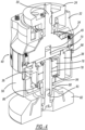
FIG. 1 is a perspective view of a rotating tool according to the disclosure. -
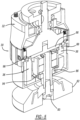
FIG. 2 is a perspective view partially in cross-section of the tool ofFIG. 1 . -
FIG. 3 is an exploded view of the adjustable stroke device. -
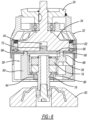
FIG. 4 is a cross-section view along line 4-4 ofFIG. 1 . -
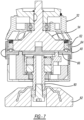
FIGS. 5 is a cross-section view likeFig. 4 with the stroke adjustor rotated 180°. -
FIG. 6 is a cross-section view ofFIG. 1 along line 6-6 thereof. -
FIG. 7 s a cross-secton view likeFIG. 6 with the stroke adjuster being rotated. -
FIG. 8 is a cross-section view likeFIG. 6 after rotation. -
FiG. 9 is an exploded perspective of the adjustable stroke device housing. - Example embodiments will now be described more fully with reference to the accompanying drawings.
- Turning to the figures, a tool is illustrated with an adjustable stroke device and is designated with the
reference numeral 10. The tool includes amotor 12, a power source 14 and aswitch 16 for activating and deactivating the power source. The power source is shown as a cord but could be rechargeable batteries. The motor includes apinion 18 positioned inside thehead housing 26 of the tool. Thedrivetrain head housing 26 includes a cavity to house adrivetrain 22. Thedrivetrain 22 includes abevel gear 24 meshing with thepinion 18. Thebevel gear 24 is coupled with theadjustment stroke device 30 which is mounted, via ahousing 32, with the bottom of thehead housing 26. - The
adjustment stroke device 30 includes adrive hub 34, aworkpiece mounting assembly 36 as a mountingassembly 36, acounterbalance mechanism 38 as acounterweight 38, astroke adjustment mechanism 40 asstroke adjuster 40 and acover 42. Thedrive hub 34 and cover 42 form a housing defining a cavity. - The
drive hub 34 includes abody 44 having aflange 46 and a pair ofwings 48. Adriveshaft 50 extends from thebody 44 and abearing 52. Theflange 46 is positioned around an extendingflange 31 on thehousing 32. Thedriveshaft 50 passes through thehousing 32 and is received by anadditional bearing 54 in thedrivetrain head housing 26. Ultimately, thedriveshaft 50 is coupled with thebevel gear 24 to provide rotation to thedrive hub 34. - The
drive hub wings 48 are separated by openings that receive thewings 56 from thecover 42 to form the cylindrical housing. - An inner body surface 58 is formed on the
body 44 between the wings 48 (seeFig. 9 ). The surface 58 provides a cutout to receive thecam plate 66 of thestroke adjustment mechanism 40. Also, the inner surface 58 includes a plurality of detent bores 60. Two detent bores 60 are shown, however depending upon the number of positions of theadjustable stroke device 30, more bores may be included. The detent bores 60 receive detent pins 62. The function of the detent pins 62 will be explained later. - The
stroke adjustment mechanism 40 includes aring 64 asadjuster ring 64 and acam 66 as part of a cam mechanism. Thering 64 is positioned around thedrive hub 34 and cover 42 as illustrated inFIG. 1 . Thering 64 includes acam plate 66 directly secured to thering 64. Thecam plate 66 includescam slots 68 and detent holes 69. Thering 64 is manually manipulated, rotated, by the user to move theadjustable stroker device 30 between operating positions. Also, ashaft 70 extends from thecam plate 66. The shaft 65 fits in abore 45 in thebody 44. This enables rotation of thestroke adjustment mechanism 40 and thedrive hub 34. Thecam plate 66 secures thestroke adjustment mechanism 40 with thedrive hub 34. Generally, this is accomplished via a C-clip. - The
workpiece mounting assembly 36 includes a bearingcarriage 72 and aU-shaped body portion 74. The bearingcarriage 72 receives bearing 76 and aspindle 78. Thespindle 78 extends through the bearings and bearingcarriage 72. It has anexternal portion 80 that includes a threaded bore 81 to receive abacking plate 82 andfastener 83. The adjustmentworkpiece mounting assembly 36 also includes alocking gear 86. Thelocking gear 86 engages thecounterbalance mechanism 38 to lock theworkpiece mounting assembly 36 in a pure rotation position. - The
U-shaped body portion 74 includes apin 88. Thepin 88 is received in one of thecam slots 68. Thus, theworkpiece mounting assembly 36 is moved with respect to thecounterbalance mechanism 38 upon rotation of thestroke adjustment mechanism 40. - The
counterbalance mechanism 38 includes abody 90 with a plurality ofstep portions 92. Thebody 90 has an overall ring shape with an elliptical configuration. The inner surface of thebody 90 includes a plurality ofteeth 94. Theteeth 94 engage with thelocking gear 86 as mentioned above to position theadjustable stroke device 30 in a purely rotational position. One of thesteps 92 include apin 98 that is positioned in one of thecam slots 68. Thepin 98 is positioned in theslot 68 opposite of the workpiece mountingassembly pin 88. Thus, as thestroke adjuster ring 64 is rotated, thecounterbalance mechanism 38 and theworkpiece mounting assembly 36 are moved away or towards one another. In the purely rotation position, thelock gear 86 engages theteeth 94 as illustrated in FIG. 5A. - The
cover 42 includes a base 100 that covers the bottom of thestroke adjuster 30. Thespindle portion 80 extends through thecover base opening 102 to enable connection with thebacking plate 82. Thecover wings 56 insert in the openings between thedrive hub wings 48. This provides a substantially continuous cylindrical housing. Thecover 42 is secured to thedrive hub 34 viascrews 104. Thus, thecounterbalance mechanism 38 as well as theworkpiece mounting assembly 36 are positioned inside of thecover 42 and drivehub 34 housing. - Turning to
FIG. 6 , the detent pins 62 are illustrated. The detent pins 62 are received in the cam plate holes 69 locking thestroke adjustment mechanism 40 in a rotary mode position or in a dual action mode position. A biasing member is positioned in thebore 60 so that upon rotation of thestroke adjustment mechanism 40, thecam plate 66 can move over thedetent pin 62 into the next position where thedetent pin 62 is received in anotherdetent hole 69. - Also, as can be seen in FIGS. 6A and 6B, the
cam plate 66 is positioned on the inner surface 58 of thehub body 44 defined by the cutout. Thecam plate 66 rotates on the surface between positions. - In operation, the
stroke adjustment mechanism 40ring 64 is rotated. As this occurs, the detent pins 62 are biased away from thecam plate 66 releasing thecam plate 66 from the detent pins 62. Thering 64 continues to turn or rotate until thedetent pin 62 engages thenext detent hole 69 in thecam plate 66. As this occurs, theadjustable stroke device 30 is locked into a position. The positions move from a purely rotational position to a dual action position. - As the
ring 64 is rotated, thepins slots 66 are moved. As this occurs, theworkpiece mounting assembly 36 andcounterbalance mechanism 38 are moved either toward one another or away from one another. In a rotary only position, the workpiece mountingassembly locking gear 86 engages theteeth 94 of thecounterbalance mechanism 38. This provides rotational only movement. As theworkpiece mounting assembly 36 and counterbalance 38 mechanisms are moved away from one another, theworkpiece mounting assembly 36 freely rotates in thecounterweight 38 and housing providing the dual action rotary and orbital movement. - Accordingly, the
activation switch 16 energizes the motor which rotates thespindle 50 which, in turn, rotates thedrive hub 34. This enables thebacking plate 82 to be rotated with thecounterbalance mechanism 38 balancing the rotational imbalance due to thespindle 78 being offset from the central axis of thespindle 50. Thus, thespindle 78 rotates theworkpiece backing plate 82 at a stroke away from the central axis.
Claims (11)
- Adjustable stroke device (30) for a random orbital machine (10) comprising:a housing (34, 42) having a central axis and a wall defining a cavity;at least one counterweight (38) movably disposed at least partially within the cavity;a mounting assembly (36) disposed at least partially within the cavity, the mounting assembly (36) including a workpiece attachment mechanism (78, 80, 81, 83); anda stroke adjuster (40) coupling the at least one counterweight (38) with the mounting assembly (36), the stroke adjuster (40) enabling the at least one counterweight (38) and mounting assembly (36) to move with respect to one another such that a distance between the at least one counterweight (38) and the mounting assembly (36) may be variably adjusted which, in turn, variably adjust a stroke radius of the workpiece attachment mechanism (78, 80, 81, 83) with respect to the central axis of the housing (34, 42),characterized in the stroke adjuster (40) including an adjuster ring (64) and a cam mechanism (65, 66, 68) secured with the adjuster ring (64).
- The adjustable stroke device of Claim 1, wherein the adjuster ring (64) surrounding the wall of the housing (34, 42), the adjuster ring (64) is only rotatable around the central axis.
- The adjustable stroke device of Claim 1, wherein the counterweight (38) engages the cam mechanism (65, 66, 68) for moving the counterweight (38) in response to cam movement.
- The adjustable stroke device of Claim 2, wherein the mounting assembly (36) includes a bearing carriage (72) engaging the cam mechanism (65, 66, 68) for moving the mounting assembly (36) in response to cam movement.
- The adjustable stroke device of Claim 1, wherein the workpiece attachment mechanism (78, 80, 81, 83) further comprises a spindle (78), the spindle (78) coupling with a bearing carriage (72).
- The adjustable stroke device of Claim 2, further comprising a locking mechanism (86, 94) associated with the mounting assembly (36) to lock the drive in a rotational position.
- The adjustable stroke device of Claim 2, wherein the cam mechanism (65, 66, 68) is directly secured to the adjuster ring (64).
- The adjustable stroke device of Claim 1, further comprising at least one detent (60, 62, 69) for securing the stroke adjuster (40) in position.
- The adjustable stroke device of Claim 1, further comprising a plurality of detents (60, 62, 69), each detent (60, 62, 69) securing the stroke adjuster (40) in a different operating position.
- The adjustable stroke device of Claim 1, wherein the housing (34, 42) includes a drive hub (34) and a cover (42).
- The adjustable stroke device of Claim 1, wherein the counterweight (38) is fully disposed in the cavity.
Priority Applications (1)
| Application Number | Priority Date | Filing Date | Title |
|---|---|---|---|
| EP24211766.1A EP4481235A3 (en) | 2021-01-20 | 2022-01-14 | Adjustable stroke device with cam |
Applications Claiming Priority (1)
| Application Number | Priority Date | Filing Date | Title |
|---|---|---|---|
| US17/152,976 US12078227B2 (en) | 2021-01-20 | 2021-01-20 | Adjustable stroke device with cam |
Related Child Applications (1)
| Application Number | Title | Priority Date | Filing Date |
|---|---|---|---|
| EP24211766.1A Division EP4481235A3 (en) | 2021-01-20 | 2022-01-14 | Adjustable stroke device with cam |
Publications (2)
| Publication Number | Publication Date |
|---|---|
| EP4088862A1 EP4088862A1 (en) | 2022-11-16 |
| EP4088862B1 true EP4088862B1 (en) | 2024-12-04 |
Family
ID=79686971
Family Applications (2)
| Application Number | Title | Priority Date | Filing Date |
|---|---|---|---|
| EP22151499.5A Active EP4088862B1 (en) | 2021-01-20 | 2022-01-14 | Adjustable stroke device with cam |
| EP24211766.1A Pending EP4481235A3 (en) | 2021-01-20 | 2022-01-14 | Adjustable stroke device with cam |
Family Applications After (1)
| Application Number | Title | Priority Date | Filing Date |
|---|---|---|---|
| EP24211766.1A Pending EP4481235A3 (en) | 2021-01-20 | 2022-01-14 | Adjustable stroke device with cam |
Country Status (12)
| Country | Link |
|---|---|
| US (3) | US12078227B2 (en) |
| EP (2) | EP4088862B1 (en) |
| JP (1) | JP2022112009A (en) |
| KR (1) | KR20220105613A (en) |
| CN (1) | CN114800183A (en) |
| AR (1) | AR124653A1 (en) |
| AU (1) | AU2022200129A1 (en) |
| BR (1) | BR102022000869A2 (en) |
| CA (1) | CA3146176A1 (en) |
| ES (1) | ES3007651T3 (en) |
| MX (1) | MX2022000838A (en) |
| PL (1) | PL4088862T3 (en) |
Families Citing this family (4)
| Publication number | Priority date | Publication date | Assignee | Title |
|---|---|---|---|---|
| US11493115B2 (en) | 2017-10-30 | 2022-11-08 | Lake Country Tool, Llc | Adjustable stroke device with cam |
| US12078227B2 (en) | 2021-01-20 | 2024-09-03 | Lake Country Tool, Llc | Adjustable stroke device with cam |
| CN115435020B (en) * | 2022-09-22 | 2025-07-04 | 安徽中烟工业有限责任公司 | A stroke-adjustable reciprocating mechanism |
| US20250135598A1 (en) * | 2023-10-30 | 2025-05-01 | Lake Country Tool, Llc | Adjustable Stroke Device With Cam |
Family Cites Families (41)
| Publication number | Priority date | Publication date | Assignee | Title |
|---|---|---|---|---|
| US169753A (en) | 1875-11-09 | Improvement in dental polishing-tools | ||
| CA977583A (en) | 1972-09-13 | 1975-11-11 | Graham C. Grant | Stroke varying mechanism |
| US4328718A (en) | 1980-08-26 | 1982-05-11 | Emerson Electric Co. | Variable oscillator drive mechanism |
| GB8407058D0 (en) | 1984-03-19 | 1984-04-26 | Black & Decker Inc | Attachments for power tools |
| IT209516Z2 (en) | 1986-12-22 | 1988-10-10 | Valentini Guido | PORTABLE ELECTRIC TOOL WITH BALANCED ORBITAL MOVEMENT. |
| US5020281A (en) | 1989-04-03 | 1991-06-04 | American Pneumatic Technologies, Inc. | High speed rotary hand tool with adjustable head coupling |
| US5134777A (en) | 1991-12-05 | 1992-08-04 | Skil Corporation | Adjustable stroke reciprocating mechanism for a power tool |
| JP3063872B2 (en) | 1992-06-08 | 2000-07-12 | 株式会社マキタ | Polishing machine |
| DK172770B1 (en) | 1996-04-17 | 1999-07-12 | Tiromat Kromer & Grebe Gmbh & | Flow packing type packaging machine with tool jaw adjustment |
| DE19629989C2 (en) | 1996-07-25 | 1999-01-28 | Metabowerke Kg | Grinder with a tool driven by a drive motor with an eccentric stroke |
| WO1999021686A1 (en) | 1997-10-28 | 1999-05-06 | Romolo Bertani | Device for supporting a mandrel with angular transmission |
| US5879228A (en) | 1997-11-14 | 1999-03-09 | Sun; Yung-Yung | Pneumatic grinding/polishing machine |
| ES2193316T3 (en) | 1997-11-24 | 2003-11-01 | Grob Ernst Fa | PROCEDURE AND DEVICE FOR COLD TRAINING OF HOLLOW PARTS. |
| US6009767A (en) | 1998-04-23 | 2000-01-04 | Rudolph; Gary | Same-RPM rotary motion to eccentric rotary motion conversion |
| US6062960A (en) | 1998-04-27 | 2000-05-16 | Ryobi North America, Inc. | Orbital tool |
| US5947804A (en) | 1998-04-27 | 1999-09-07 | Ryobi North America, Inc. | Adjustable eccentricity orbital tool |
| US6206771B1 (en) | 1999-01-25 | 2001-03-27 | Dynabrade, Inc. | Balancer for orbital abrading machine |
| DE59908214D1 (en) | 1999-10-14 | 2004-02-05 | Storz Karl Gmbh & Co | SWIVEL JOINT FOR MEDICAL INSTRUMENTS |
| JP2001179591A (en) | 1999-12-24 | 2001-07-03 | Hitachi Koki Co Ltd | Orbital sander |
| US7658012B2 (en) | 2002-12-23 | 2010-02-09 | Milwaukee Electric Tool Corporation | Drive mechanism and power tool |
| US7022002B2 (en) | 2004-03-03 | 2006-04-04 | Dynabrade, Inc. | Modular counterweight apparatus for an orbital abrading machine |
| EP2027969B1 (en) | 2004-04-13 | 2011-03-23 | Black & Decker, Inc. | Electric sander and motor control therefor |
| US7241209B2 (en) | 2004-08-13 | 2007-07-10 | General Electric Company | Orbiting polishing tool |
| DE102004055271A1 (en) | 2004-11-17 | 2006-05-18 | Robert Bosch Gmbh | eccentric |
| US7721861B2 (en) | 2005-02-04 | 2010-05-25 | Positec Power Tools (Suzhou) Co., Ltd. | Clutch mechanism for use in power tools |
| CN100453271C (en) | 2005-02-04 | 2009-01-21 | 苏州宝时得电动工具有限公司 | Eccentricity regulating mechanism |
| WO2007073323A1 (en) * | 2005-12-20 | 2007-06-28 | Dentatus Ab | Vibration dampened hand-held power tool |
| FI126233B (en) | 2006-02-23 | 2016-08-31 | Oy Kwh Mirka Ab | Oscillating grinder |
| US7713110B2 (en) | 2006-09-05 | 2010-05-11 | Dynabrade, Inc. | Locking random orbital dual-action head assembly |
| US7238095B1 (en) | 2006-11-20 | 2007-07-03 | Storm Pneumtic Tool Co., Ltd. | Pneumatic grinder with improved muffling structure |
| DE102007062560A1 (en) | 2007-12-22 | 2009-06-25 | J. Wagner Gmbh | surface grinding machine |
| EP2127808A1 (en) | 2008-05-29 | 2009-12-02 | Black & Decker, Inc. | Power tool |
| US8740669B2 (en) | 2011-07-28 | 2014-06-03 | Omni Cubed, Inc. | Damage prevention tool and method |
| US10518384B2 (en) | 2015-11-02 | 2019-12-31 | Lake Country Tool, Llc | Adjustable stroke mechanism for random orbital machine |
| US10144106B2 (en) | 2015-11-02 | 2018-12-04 | Lake Country Manufacturing, Inc. | Adjustable stroke mechanism for random orbital machine |
| CN107009327B (en) * | 2016-01-27 | 2021-03-16 | 苏州宝时得电动工具有限公司 | Swing power tool |
| CN206356999U (en) | 2016-12-28 | 2017-07-28 | 沪东重机有限公司 | Milling tool for combustion gas control block inverted cone bottom of chamber sealing surface |
| US11493115B2 (en) | 2017-10-30 | 2022-11-08 | Lake Country Tool, Llc | Adjustable stroke device with cam |
| US11592055B2 (en) * | 2018-08-30 | 2023-02-28 | Lake Country Tool, Llc | Adjustable stroke device with cam |
| EP3693132B1 (en) * | 2019-02-08 | 2023-09-06 | Guido Valentini | Hand-held and hand-guided random orbital polishing or sanding power tool |
| US12078227B2 (en) * | 2021-01-20 | 2024-09-03 | Lake Country Tool, Llc | Adjustable stroke device with cam |
-
2021
- 2021-01-20 US US17/152,976 patent/US12078227B2/en active Active
-
2022
- 2022-01-11 AU AU2022200129A patent/AU2022200129A1/en not_active Abandoned
- 2022-01-14 EP EP22151499.5A patent/EP4088862B1/en active Active
- 2022-01-14 EP EP24211766.1A patent/EP4481235A3/en active Pending
- 2022-01-14 ES ES22151499T patent/ES3007651T3/en active Active
- 2022-01-14 PL PL22151499.5T patent/PL4088862T3/en unknown
- 2022-01-17 BR BR102022000869-8A patent/BR102022000869A2/en not_active Application Discontinuation
- 2022-01-17 AR ARP220100076A patent/AR124653A1/en active IP Right Grant
- 2022-01-18 JP JP2022005415A patent/JP2022112009A/en active Pending
- 2022-01-19 CA CA3146176A patent/CA3146176A1/en active Pending
- 2022-01-20 KR KR1020220008410A patent/KR20220105613A/en active Pending
- 2022-01-20 MX MX2022000838A patent/MX2022000838A/en unknown
- 2022-01-20 CN CN202210064574.XA patent/CN114800183A/en active Pending
-
2024
- 2024-07-30 US US18/788,341 patent/US12449024B2/en active Active
-
2025
- 2025-09-19 US US19/333,488 patent/US20260016071A1/en active Pending
Also Published As
| Publication number | Publication date |
|---|---|
| AU2022200129A1 (en) | 2022-08-04 |
| US12078227B2 (en) | 2024-09-03 |
| EP4088862A1 (en) | 2022-11-16 |
| EP4481235A3 (en) | 2025-03-26 |
| JP2022112009A (en) | 2022-08-01 |
| MX2022000838A (en) | 2022-07-21 |
| US20260016071A1 (en) | 2026-01-15 |
| CA3146176A1 (en) | 2022-07-20 |
| PL4088862T3 (en) | 2025-03-24 |
| KR20220105613A (en) | 2022-07-27 |
| US20220228653A1 (en) | 2022-07-21 |
| US12449024B2 (en) | 2025-10-21 |
| US20240384779A1 (en) | 2024-11-21 |
| ES3007651T3 (en) | 2025-03-20 |
| EP4481235A2 (en) | 2024-12-25 |
| BR102022000869A2 (en) | 2022-07-26 |
| AR124653A1 (en) | 2023-04-19 |
| CN114800183A (en) | 2022-07-29 |
Similar Documents
| Publication | Publication Date | Title |
|---|---|---|
| US12449024B2 (en) | Adjustable stroke device with cam | |
| US11674571B2 (en) | Adjustable stroke device with cam | |
| US12553465B2 (en) | Adjustable stroke device with cam | |
| US20250153306A1 (en) | Adjustable Stroke Device | |
| US20250135598A1 (en) | Adjustable Stroke Device With Cam |
Legal Events
| Date | Code | Title | Description |
|---|---|---|---|
| PUAI | Public reference made under article 153(3) epc to a published international application that has entered the european phase |
Free format text: ORIGINAL CODE: 0009012 |
|
| STAA | Information on the status of an ep patent application or granted ep patent |
Free format text: STATUS: THE APPLICATION HAS BEEN PUBLISHED |
|
| AK | Designated contracting states |
Kind code of ref document: A1 Designated state(s): AL AT BE BG CH CY CZ DE DK EE ES FI FR GB GR HR HU IE IS IT LI LT LU LV MC MK MT NL NO PL PT RO RS SE SI SK SM TR |
|
| STAA | Information on the status of an ep patent application or granted ep patent |
Free format text: STATUS: REQUEST FOR EXAMINATION WAS MADE |
|
| 17P | Request for examination filed |
Effective date: 20230515 |
|
| RBV | Designated contracting states (corrected) |
Designated state(s): AL AT BE BG CH CY CZ DE DK EE ES FI FR GB GR HR HU IE IS IT LI LT LU LV MC MK MT NL NO PL PT RO RS SE SI SK SM TR |
|
| GRAP | Despatch of communication of intention to grant a patent |
Free format text: ORIGINAL CODE: EPIDOSNIGR1 |
|
| STAA | Information on the status of an ep patent application or granted ep patent |
Free format text: STATUS: GRANT OF PATENT IS INTENDED |
|
| RIC1 | Information provided on ipc code assigned before grant |
Ipc: F16H 53/02 20060101ALN20240704BHEP Ipc: F16H 27/02 20060101ALI20240704BHEP Ipc: F16H 25/10 20060101ALI20240704BHEP Ipc: B24B 47/12 20060101ALI20240704BHEP Ipc: B24B 23/04 20060101AFI20240704BHEP |
|
| INTG | Intention to grant announced |
Effective date: 20240716 |
|
| RAP3 | Party data changed (applicant data changed or rights of an application transferred) |
Owner name: LAKE COUNTRY TOOL, LLC |
|
| RIN1 | Information on inventor provided before grant (corrected) |
Inventor name: MCLAIN, SCOTT S. |
|
| P01 | Opt-out of the competence of the unified patent court (upc) registered |
Free format text: CASE NUMBER: APP_50306/2024 Effective date: 20240905 |
|
| GRAS | Grant fee paid |
Free format text: ORIGINAL CODE: EPIDOSNIGR3 |
|
| GRAA | (expected) grant |
Free format text: ORIGINAL CODE: 0009210 |
|
| STAA | Information on the status of an ep patent application or granted ep patent |
Free format text: STATUS: THE PATENT HAS BEEN GRANTED |
|
| AK | Designated contracting states |
Kind code of ref document: B1 Designated state(s): AL AT BE BG CH CY CZ DE DK EE ES FI FR GB GR HR HU IE IS IT LI LT LU LV MC MK MT NL NO PL PT RO RS SE SI SK SM TR |
|
| REG | Reference to a national code |
Ref country code: CH Ref legal event code: EP |
|
| REG | Reference to a national code |
Ref country code: DE Ref legal event code: R096 Ref document number: 602022008261 Country of ref document: DE |
|
| REG | Reference to a national code |
Ref country code: IE Ref legal event code: FG4D |
|
| REG | Reference to a national code |
Ref country code: NL Ref legal event code: FP |
|
| REG | Reference to a national code |
Ref country code: ES Ref legal event code: FG2A Ref document number: 3007651 Country of ref document: ES Kind code of ref document: T3 Effective date: 20250320 |
|
| REG | Reference to a national code |
Ref country code: LT Ref legal event code: MG9D |
|
| PG25 | Lapsed in a contracting state [announced via postgrant information from national office to epo] |
Ref country code: HR Free format text: LAPSE BECAUSE OF FAILURE TO SUBMIT A TRANSLATION OF THE DESCRIPTION OR TO PAY THE FEE WITHIN THE PRESCRIBED TIME-LIMIT Effective date: 20241204 |
|
| PG25 | Lapsed in a contracting state [announced via postgrant information from national office to epo] |
Ref country code: FI Free format text: LAPSE BECAUSE OF FAILURE TO SUBMIT A TRANSLATION OF THE DESCRIPTION OR TO PAY THE FEE WITHIN THE PRESCRIBED TIME-LIMIT Effective date: 20241204 |
|
| PG25 | Lapsed in a contracting state [announced via postgrant information from national office to epo] |
Ref country code: BG Free format text: LAPSE BECAUSE OF FAILURE TO SUBMIT A TRANSLATION OF THE DESCRIPTION OR TO PAY THE FEE WITHIN THE PRESCRIBED TIME-LIMIT Effective date: 20241204 |
|
| PG25 | Lapsed in a contracting state [announced via postgrant information from national office to epo] |
Ref country code: NO Free format text: LAPSE BECAUSE OF FAILURE TO SUBMIT A TRANSLATION OF THE DESCRIPTION OR TO PAY THE FEE WITHIN THE PRESCRIBED TIME-LIMIT Effective date: 20250304 |
|
| PG25 | Lapsed in a contracting state [announced via postgrant information from national office to epo] |
Ref country code: LV Free format text: LAPSE BECAUSE OF FAILURE TO SUBMIT A TRANSLATION OF THE DESCRIPTION OR TO PAY THE FEE WITHIN THE PRESCRIBED TIME-LIMIT Effective date: 20241204 Ref country code: GR Free format text: LAPSE BECAUSE OF FAILURE TO SUBMIT A TRANSLATION OF THE DESCRIPTION OR TO PAY THE FEE WITHIN THE PRESCRIBED TIME-LIMIT Effective date: 20250305 |
|
| PG25 | Lapsed in a contracting state [announced via postgrant information from national office to epo] |
Ref country code: RS Free format text: LAPSE BECAUSE OF FAILURE TO SUBMIT A TRANSLATION OF THE DESCRIPTION OR TO PAY THE FEE WITHIN THE PRESCRIBED TIME-LIMIT Effective date: 20250304 |
|
| REG | Reference to a national code |
Ref country code: AT Ref legal event code: MK05 Ref document number: 1747656 Country of ref document: AT Kind code of ref document: T Effective date: 20241204 |
|
| PG25 | Lapsed in a contracting state [announced via postgrant information from national office to epo] |
Ref country code: SM Free format text: LAPSE BECAUSE OF FAILURE TO SUBMIT A TRANSLATION OF THE DESCRIPTION OR TO PAY THE FEE WITHIN THE PRESCRIBED TIME-LIMIT Effective date: 20241204 |
|
| PG25 | Lapsed in a contracting state [announced via postgrant information from national office to epo] |
Ref country code: IS Free format text: LAPSE BECAUSE OF FAILURE TO SUBMIT A TRANSLATION OF THE DESCRIPTION OR TO PAY THE FEE WITHIN THE PRESCRIBED TIME-LIMIT Effective date: 20250404 |
|
| PG25 | Lapsed in a contracting state [announced via postgrant information from national office to epo] |
Ref country code: PT Free format text: LAPSE BECAUSE OF FAILURE TO SUBMIT A TRANSLATION OF THE DESCRIPTION OR TO PAY THE FEE WITHIN THE PRESCRIBED TIME-LIMIT Effective date: 20250404 |
|
| PG25 | Lapsed in a contracting state [announced via postgrant information from national office to epo] |
Ref country code: EE Free format text: LAPSE BECAUSE OF FAILURE TO SUBMIT A TRANSLATION OF THE DESCRIPTION OR TO PAY THE FEE WITHIN THE PRESCRIBED TIME-LIMIT Effective date: 20241204 |
|
| PG25 | Lapsed in a contracting state [announced via postgrant information from national office to epo] |
Ref country code: AT Free format text: LAPSE BECAUSE OF FAILURE TO SUBMIT A TRANSLATION OF THE DESCRIPTION OR TO PAY THE FEE WITHIN THE PRESCRIBED TIME-LIMIT Effective date: 20241204 Ref country code: RO Free format text: LAPSE BECAUSE OF FAILURE TO SUBMIT A TRANSLATION OF THE DESCRIPTION OR TO PAY THE FEE WITHIN THE PRESCRIBED TIME-LIMIT Effective date: 20241204 |
|
| PG25 | Lapsed in a contracting state [announced via postgrant information from national office to epo] |
Ref country code: SK Free format text: LAPSE BECAUSE OF FAILURE TO SUBMIT A TRANSLATION OF THE DESCRIPTION OR TO PAY THE FEE WITHIN THE PRESCRIBED TIME-LIMIT Effective date: 20241204 |
|
| PG25 | Lapsed in a contracting state [announced via postgrant information from national office to epo] |
Ref country code: CZ Free format text: LAPSE BECAUSE OF FAILURE TO SUBMIT A TRANSLATION OF THE DESCRIPTION OR TO PAY THE FEE WITHIN THE PRESCRIBED TIME-LIMIT Effective date: 20241204 |
|
| REG | Reference to a national code |
Ref country code: DE Ref legal event code: R097 Ref document number: 602022008261 Country of ref document: DE |
|
| PG25 | Lapsed in a contracting state [announced via postgrant information from national office to epo] |
Ref country code: SE Free format text: LAPSE BECAUSE OF FAILURE TO SUBMIT A TRANSLATION OF THE DESCRIPTION OR TO PAY THE FEE WITHIN THE PRESCRIBED TIME-LIMIT Effective date: 20241204 |
|
| PG25 | Lapsed in a contracting state [announced via postgrant information from national office to epo] |
Ref country code: MC Free format text: LAPSE BECAUSE OF FAILURE TO SUBMIT A TRANSLATION OF THE DESCRIPTION OR TO PAY THE FEE WITHIN THE PRESCRIBED TIME-LIMIT Effective date: 20241204 Ref country code: LU Free format text: LAPSE BECAUSE OF NON-PAYMENT OF DUE FEES Effective date: 20250114 |
|
| PG25 | Lapsed in a contracting state [announced via postgrant information from national office to epo] |
Ref country code: DK Free format text: LAPSE BECAUSE OF FAILURE TO SUBMIT A TRANSLATION OF THE DESCRIPTION OR TO PAY THE FEE WITHIN THE PRESCRIBED TIME-LIMIT Effective date: 20241204 |
|
| PLBE | No opposition filed within time limit |
Free format text: ORIGINAL CODE: 0009261 |
|
| STAA | Information on the status of an ep patent application or granted ep patent |
Free format text: STATUS: NO OPPOSITION FILED WITHIN TIME LIMIT |
|
| REG | Reference to a national code |
Ref country code: CH Ref legal event code: L10 Free format text: ST27 STATUS EVENT CODE: U-0-0-L10-L00 (AS PROVIDED BY THE NATIONAL OFFICE) Effective date: 20251015 |
|
| PG25 | Lapsed in a contracting state [announced via postgrant information from national office to epo] |
Ref country code: BE Free format text: LAPSE BECAUSE OF NON-PAYMENT OF DUE FEES Effective date: 20250131 |
|
| REG | Reference to a national code |
Ref country code: BE Ref legal event code: MM Effective date: 20250131 |
|
| 26N | No opposition filed |
Effective date: 20250905 |
|
| PG25 | Lapsed in a contracting state [announced via postgrant information from national office to epo] |
Ref country code: IE Free format text: LAPSE BECAUSE OF NON-PAYMENT OF DUE FEES Effective date: 20250114 |
|
| PGFP | Annual fee paid to national office [announced via postgrant information from national office to epo] |
Ref country code: PL Payment date: 20251218 Year of fee payment: 5 |
|
| REG | Reference to a national code |
Ref country code: CH Ref legal event code: U11 Free format text: ST27 STATUS EVENT CODE: U-0-0-U10-U11 (AS PROVIDED BY THE NATIONAL OFFICE) Effective date: 20260201 |
|
| PGFP | Annual fee paid to national office [announced via postgrant information from national office to epo] |
Ref country code: NL Payment date: 20260126 Year of fee payment: 5 |
|
| PGFP | Annual fee paid to national office [announced via postgrant information from national office to epo] |
Ref country code: GB Payment date: 20260127 Year of fee payment: 5 |
|
| PGFP | Annual fee paid to national office [announced via postgrant information from national office to epo] |
Ref country code: ES Payment date: 20260202 Year of fee payment: 5 |
|
| PGFP | Annual fee paid to national office [announced via postgrant information from national office to epo] |
Ref country code: DE Payment date: 20260128 Year of fee payment: 5 |
|
| PGFP | Annual fee paid to national office [announced via postgrant information from national office to epo] |
Ref country code: IT Payment date: 20260121 Year of fee payment: 5 |
|
| PGFP | Annual fee paid to national office [announced via postgrant information from national office to epo] |
Ref country code: FR Payment date: 20260126 Year of fee payment: 5 |
|
| PGFP | Annual fee paid to national office [announced via postgrant information from national office to epo] |
Ref country code: TR Payment date: 20260112 Year of fee payment: 5 |
|
| PGFP | Annual fee paid to national office [announced via postgrant information from national office to epo] |
Ref country code: CH Payment date: 20260201 Year of fee payment: 5 |
|
| PG25 | Lapsed in a contracting state [announced via postgrant information from national office to epo] |
Ref country code: CY Free format text: LAPSE BECAUSE OF FAILURE TO SUBMIT A TRANSLATION OF THE DESCRIPTION OR TO PAY THE FEE WITHIN THE PRESCRIBED TIME-LIMIT Effective date: 20241204 |
|
| PG25 | Lapsed in a contracting state [announced via postgrant information from national office to epo] |
Ref country code: LT Free format text: LAPSE BECAUSE OF FAILURE TO SUBMIT A TRANSLATION OF THE DESCRIPTION OR TO PAY THE FEE WITHIN THE PRESCRIBED TIME-LIMIT Effective date: 20241204 |