EP4088849B1 - Multi-diameter power pin and receiving socket for an arc processing system - Google Patents
Multi-diameter power pin and receiving socket for an arc processing system Download PDFInfo
- Publication number
- EP4088849B1 EP4088849B1 EP22161066.0A EP22161066A EP4088849B1 EP 4088849 B1 EP4088849 B1 EP 4088849B1 EP 22161066 A EP22161066 A EP 22161066A EP 4088849 B1 EP4088849 B1 EP 4088849B1
- Authority
- EP
- European Patent Office
- Prior art keywords
- power pin
- diameter
- receiving block
- liner
- distal
- Prior art date
- Legal status (The legal status is an assumption and is not a legal conclusion. Google has not performed a legal analysis and makes no representation as to the accuracy of the status listed.)
- Active
Links
Images







Classifications
-
- H—ELECTRICITY
- H01—ELECTRIC ELEMENTS
- H01R—ELECTRICALLY-CONDUCTIVE CONNECTIONS; STRUCTURAL ASSOCIATIONS OF A PLURALITY OF MUTUALLY-INSULATED ELECTRICAL CONNECTING ELEMENTS; COUPLING DEVICES; CURRENT COLLECTORS
- H01R13/00—Details of coupling devices of the kinds covered by groups H01R12/70 or H01R24/00 - H01R33/00
- H01R13/62—Means for facilitating engagement or disengagement of coupling parts or for holding them in engagement
- H01R13/639—Additional means for holding or locking coupling parts together, after engagement, e.g. separate keylock, retainer strap
-
- B—PERFORMING OPERATIONS; TRANSPORTING
- B23—MACHINE TOOLS; METAL-WORKING NOT OTHERWISE PROVIDED FOR
- B23K—SOLDERING OR UNSOLDERING; WELDING; CLADDING OR PLATING BY SOLDERING OR WELDING; CUTTING BY APPLYING HEAT LOCALLY, e.g. FLAME CUTTING; WORKING BY LASER BEAM
- B23K9/00—Arc welding or cutting
- B23K9/32—Accessories
- B23K9/323—Combined coupling means, e.g. gas, electricity, water or the like
-
- H—ELECTRICITY
- H01—ELECTRIC ELEMENTS
- H01R—ELECTRICALLY-CONDUCTIVE CONNECTIONS; STRUCTURAL ASSOCIATIONS OF A PLURALITY OF MUTUALLY-INSULATED ELECTRICAL CONNECTING ELEMENTS; COUPLING DEVICES; CURRENT COLLECTORS
- H01R13/00—Details of coupling devices of the kinds covered by groups H01R12/70 or H01R24/00 - H01R33/00
- H01R13/62—Means for facilitating engagement or disengagement of coupling parts or for holding them in engagement
- H01R13/627—Snap or like fastening
- H01R13/6276—Snap or like fastening comprising one or more balls engaging in a hole or a groove
-
- B—PERFORMING OPERATIONS; TRANSPORTING
- B23—MACHINE TOOLS; METAL-WORKING NOT OTHERWISE PROVIDED FOR
- B23K—SOLDERING OR UNSOLDERING; WELDING; CLADDING OR PLATING BY SOLDERING OR WELDING; CUTTING BY APPLYING HEAT LOCALLY, e.g. FLAME CUTTING; WORKING BY LASER BEAM
- B23K9/00—Arc welding or cutting
- B23K9/10—Other electric circuits therefor; Protective circuits; Remote controls
-
- B—PERFORMING OPERATIONS; TRANSPORTING
- B23—MACHINE TOOLS; METAL-WORKING NOT OTHERWISE PROVIDED FOR
- B23K—SOLDERING OR UNSOLDERING; WELDING; CLADDING OR PLATING BY SOLDERING OR WELDING; CUTTING BY APPLYING HEAT LOCALLY, e.g. FLAME CUTTING; WORKING BY LASER BEAM
- B23K9/00—Arc welding or cutting
- B23K9/12—Automatic feeding or moving of electrodes or work for spot or seam welding or cutting
- B23K9/133—Means for feeding electrodes, e.g. drums, rolls, motors
-
- B—PERFORMING OPERATIONS; TRANSPORTING
- B23—MACHINE TOOLS; METAL-WORKING NOT OTHERWISE PROVIDED FOR
- B23K—SOLDERING OR UNSOLDERING; WELDING; CLADDING OR PLATING BY SOLDERING OR WELDING; CUTTING BY APPLYING HEAT LOCALLY, e.g. FLAME CUTTING; WORKING BY LASER BEAM
- B23K9/00—Arc welding or cutting
- B23K9/32—Accessories
-
- H—ELECTRICITY
- H01—ELECTRIC ELEMENTS
- H01R—ELECTRICALLY-CONDUCTIVE CONNECTIONS; STRUCTURAL ASSOCIATIONS OF A PLURALITY OF MUTUALLY-INSULATED ELECTRICAL CONNECTING ELEMENTS; COUPLING DEVICES; CURRENT COLLECTORS
- H01R13/00—Details of coupling devices of the kinds covered by groups H01R12/70 or H01R24/00 - H01R33/00
- H01R13/40—Securing contact members in or to a base or case; Insulating of contact members
-
- H—ELECTRICITY
- H01—ELECTRIC ELEMENTS
- H01R—ELECTRICALLY-CONDUCTIVE CONNECTIONS; STRUCTURAL ASSOCIATIONS OF A PLURALITY OF MUTUALLY-INSULATED ELECTRICAL CONNECTING ELEMENTS; COUPLING DEVICES; CURRENT COLLECTORS
- H01R13/00—Details of coupling devices of the kinds covered by groups H01R12/70 or H01R24/00 - H01R33/00
- H01R13/46—Bases; Cases
- H01R13/52—Dustproof, splashproof, drip-proof, waterproof, or flameproof cases
- H01R13/5205—Sealing means between cable and housing, e.g. grommet
-
- H—ELECTRICITY
- H01—ELECTRIC ELEMENTS
- H01R—ELECTRICALLY-CONDUCTIVE CONNECTIONS; STRUCTURAL ASSOCIATIONS OF A PLURALITY OF MUTUALLY-INSULATED ELECTRICAL CONNECTING ELEMENTS; COUPLING DEVICES; CURRENT COLLECTORS
- H01R13/00—Details of coupling devices of the kinds covered by groups H01R12/70 or H01R24/00 - H01R33/00
- H01R13/46—Bases; Cases
- H01R13/53—Bases or cases for heavy duty; Bases or cases for high voltage with means for preventing corona or arcing
-
- H—ELECTRICITY
- H01—ELECTRIC ELEMENTS
- H01R—ELECTRICALLY-CONDUCTIVE CONNECTIONS; STRUCTURAL ASSOCIATIONS OF A PLURALITY OF MUTUALLY-INSULATED ELECTRICAL CONNECTING ELEMENTS; COUPLING DEVICES; CURRENT COLLECTORS
- H01R13/00—Details of coupling devices of the kinds covered by groups H01R12/70 or H01R24/00 - H01R33/00
- H01R13/62—Means for facilitating engagement or disengagement of coupling parts or for holding them in engagement
- H01R13/621—Bolt, set screw or screw clamp
- H01R13/6215—Bolt, set screw or screw clamp using one or more bolts
-
- H—ELECTRICITY
- H01—ELECTRIC ELEMENTS
- H01R—ELECTRICALLY-CONDUCTIVE CONNECTIONS; STRUCTURAL ASSOCIATIONS OF A PLURALITY OF MUTUALLY-INSULATED ELECTRICAL CONNECTING ELEMENTS; COUPLING DEVICES; CURRENT COLLECTORS
- H01R13/00—Details of coupling devices of the kinds covered by groups H01R12/70 or H01R24/00 - H01R33/00
- H01R13/62—Means for facilitating engagement or disengagement of coupling parts or for holding them in engagement
- H01R13/629—Additional means for facilitating engagement or disengagement of coupling parts, e.g. aligning or guiding means, levers, gas pressure electrical locking indicators, manufacturing tolerances
-
- H—ELECTRICITY
- H01—ELECTRIC ELEMENTS
- H01R—ELECTRICALLY-CONDUCTIVE CONNECTIONS; STRUCTURAL ASSOCIATIONS OF A PLURALITY OF MUTUALLY-INSULATED ELECTRICAL CONNECTING ELEMENTS; COUPLING DEVICES; CURRENT COLLECTORS
- H01R11/00—Individual connecting elements providing two or more spaced connecting locations for conductive members which are, or may be, thereby interconnected, e.g. end pieces for wires or cables supported by the wire or cable and having means for facilitating electrical connection to some other wire, terminal, or conductive member, blocks of binding posts
- H01R11/03—Individual connecting elements providing two or more spaced connecting locations for conductive members which are, or may be, thereby interconnected, e.g. end pieces for wires or cables supported by the wire or cable and having means for facilitating electrical connection to some other wire, terminal, or conductive member, blocks of binding posts characterised by the relationship between the connecting locations
- H01R11/09—Individual connecting elements providing two or more spaced connecting locations for conductive members which are, or may be, thereby interconnected, e.g. end pieces for wires or cables supported by the wire or cable and having means for facilitating electrical connection to some other wire, terminal, or conductive member, blocks of binding posts characterised by the relationship between the connecting locations the connecting locations being identical
Definitions
- the present invention relates to the field of electrical connections and, in particular, a multi-diameter power pin for a plug of a cable for an arc process system, and a socket for a multi-diameter power pin of a plug of a cable for an arc process system according to the preamble of claims 1 and 9 (see for example GB 1,036,804A ).
- welding robots include one or more arms, a torch, and a wire feeder for feeding weld wire to the torch.
- the torch is disposed at a distal end of the robot and the wire feeder is disposed between a base of the torch and the distal end.
- a cable connects the wire feeder to the torch and provides one or more of electricity, weld wire, process gas, and cooling fluid from the wire feeder. Close contact between a power pin of the plug and receiving block of a socket is desirable for proper transfer of electricity and fluids from the wire feeder to the torch cable.
- a user climbs up the robot to connect the torch cable to the wire feeder.
- the user inserts a plug of the torch cable into a socket of the wire feeder and holds it in place with one hand, while clamping the plug to a socket with the other hand.
- both hands otherwise occupied with clamping/securing the torch cable to the wire feeder, the user does not have a free hand to steady herself while perched on the robot.
- the user may be unsteady on the robot and could fall off. Consequently, the user may not properly secure the plug of the cable with the socket resulting in inefficient transfer of electricity, kinking or jamming of weld wire, and/or leakage of fluids.
- a liner is disposed in the plug and cable to protect weld wire fed through the connector.
- the liner can be installed in the cable by inserting the liner through the power pin of the plug. Once installed, the liner isolates weld wire from the electrical current and/or a fluid that flows through the power pin and cable.
- the liner is held in place by a bolt that traverses the power pin and engages a tip of the liner. The bolt may be loosened or tightened with a tool, e.g., screw driver, allen wrench, etc., but over tightening of the bolt may cause damage to the liner, which may cause the weld wire to kink.
- a plug assembly for an arc process device is disclosed in US 7,274,001B1 .
- the plug assembly has a metal plug portion for electrically coupling to a welding machine.
- the plug portion extends from an insulated rear case that is coupled to a cable hose.
- a socket conveying electrical current, shield gas, and compressed air for an arc processing device is disclosed in GB 1,036,804A .
- the socket includes a cylindrical bore having two annular grooves for receiving the shielding gas and/or compressed air and contact clamp to grip a metal sleeve of a cable.
- connection system for efficiently and safely securing a liner within a torch cable, and/or connecting a torch cable to a power source and/or wire feeder are desirable.
- a multi-diameter power pin for a plug of a cable for an arc process system is defined in claim 1.
- a socket for a multi-diameter power pin of a plug of a cable for an arc process system is defined in claim 9.
- the connector may be used for connecting and transmitting power between any two components of a high-power system, such as a power source and a cable of a plasma cutting torch.
- a conventional power pin of a plug for an arc processing operation generally includes only one or two portions having one or two diameters.
- a conventional power pin may include an attachment portion for attaching to a cable and a second portion configured to be clamped into and receive one or more gases from a receiving block of a socket.
- the entire second portion is clamped in receiving block. That is, a clamp of the receiving block is configured to bear against of the second portion.
- the second portion generally includes surface features, such as one or more grooves, bores, and/or protrusions configured to receive one or more of process gases, seals, holder screws, etc.
- the system and method for connecting a torch cable to a wire feeder presented herein include a plug having a multi-diameter power pin and a socket with a receiving block having a multi-diameter through hole, or bore, for receiving the power pin.
- the features of the power pin and receiving block allow a user to connect and secure the plug to the socket with one hand.
- an engagement mechanism disposed in the power pin engages an inner surface of the receiving block in response to inserting the pin into the receiving block.
- the engagement mechanism maintains a position of the power pin while the user clamps and secures the power pin in the receiving block.
- the user can insert the power pin into the receiving block and provisionally lock it with the engagement mechanism, let go of the torch cable, and lock the power pin in place with a clamp.
- a dedicated bearing portion of the power pin corresponding to dedicated clamping portion of the receiving block provides an improved electrical connection between the pin and receiving block as compared to conventional connectors. That is, the dedicated bearing portion and clamp provide unobstructed contact between the power pin and receiving block. Thus, electricity may be efficiently conducted between the receiving block and power pin without the drawbacks of the conventional power pin noted above.
- the power pin includes a central bore for receiving a liner that extends into the torch cable.
- the liner isolates a weld wire passing through the connector from an inner surface of the power pin and a conductor of the torch cable.
- a user can access the central bore of the power pin by removing a liner cap by hand, without using a tool, and insert the liner with the liner tip into the central bore.
- the user can dispose the liner cap over the liner tip and a distal portion of the power pin, thereby clamping the liner tip between the liner cap and power pin.
- a user can remove the liner cap, without a tool, to expose the liner tip and distal end of the power pin.
- the liner cap and liner can be easily installed, secured, and/or replaced without the drawbacks of the conventional liner and bolt arrangement noted above.
- the liner cap shape assists in guiding the power pin into the receiving block and prevents weld wire from kinking.
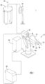
- the robot welding system 1 includes a robot 10 connected to a controller 110, a wire feeder assembly 20, a power source 130, and wire spool 140.
- the power source 130 is electrically coupled to the robot 10 and the torch 112 via the controller 110, and the wire feeder assembly 20, respectively.
- the power source 130 can provide power to components of the robot 10, controller 110, and the wire feeder assembly 20, as well as a process current for an arc process (e.g., a welding or plasma cutting operation). Additionally, the power source 130 may provide a shield gas and/or a process gas for the plasma arc process to the wire feeder.
- the controller 110 controls the movement of the robot 10 and the plasma arc process.
- a wire supply 140 provides weld wire to the wire feeder assembly 20.
- the wire supply 140 may be a bulk pack 142 or a spool 144. In some implementations, the spool 144 is disposed in the wire feeder assembly 20.
- the robot 10 includes a base 100, a first arm 102 pivotably attached to and extending from the base 100, and a second arm 104 pivotably coupled to the first arm 102, opposite the base 100.
- a torch 112 is disposed on a distal end 106 of the second arm 104, and the wire feeder assembly 20 is disposed at a coupling between the first arm 102 and second arm 104.
- this is just one example of a welding robot and the present application may be applicable to a wide variety of robots.
- a torch cable 114 connects the torch 112 to the wire feeder assembly 20.
- a connector 30 couples the torch cable 114 to the wire feeder assembly 20.
- the connector includes a socket 40 disposed at the wire feeder assembly 20 (see FIG. 2A ) and a plug 50 disposed on the torch cable 114 (see FIGS. 3A-3B ).
- the torch cable 114 transmits a process current, weld wire, and fluids (e.g., shield gas, process gas, and/or cooling fluid) from the wire feeder assembly 20 through the connector 30 and torch cable 114 to the torch 112.
- the feeder 230 includes a plurality of wire rollers 232 for pulling the weld wire from a wire supply 140 through the wire port 218 and pushing the weld wire through the socket 40.
- the control side 206 includes components and/or circuitry for receiving signals and controlling the feeder 230 based on the received signals.
- the components and/or circuitry may control one or more arc process parameters (e.g., process power, process current, voltage, process gas flow, shield gas flow, cooling fluid flow, wire feed speed, etc.).
- FIG. 2B is a perspective view of a portion of the wire feeding side 204 of the interior compartment 202.
- a receiving block 400 of the socket 40 is disposed between and aligned with the feeder 230 and the connector port 214.
- the receiving block 400 is configured to receive the plug 50 of the connector 30 and the conductor 240.
- FIGS. 3A - 3D three configurations of the connector 30 are illustrated.
- the wire feeder assembly 20 accommodating the socket 40 has been omitted for clarity.
- the plug 50 is separate and removed from the socket 40 (see FIGS. 3A and 3B ).
- the plug 50 of the connector 30 includes a distal end 52 and a proximal end 54 connected to the torch cable 114.
- a multi-diameter power pin 500 is disposed at the distal end 52.
- the socket 40 includes a receiving block 400 having a multi-diameter through hole, or central bore, 402 for receiving the power pin 500.
- configuration C2 the plug 50 is inserted into the socket 40 but is not clamped in place or otherwise locked (see FIG. 3C ).
- the power pin 500 provisionally engages an internal surface of the receiving block 400 defining the central bore 402 and holds the plug 50 in place. Consequently, the plug 50 cannot disengage the socket 40 on its own, but a user can remove the plug 50 by hand, if desired.
- the provisional engagement configuration C2 between the power pin 500 and receiving block 400 is discussed in detail below with reference to FIG. 7 .
- the socket 40 receives and clamps, or otherwise locks, the plug 50 in position with a quick release bolt 450 (see FIG. 3D ).
- the receiving block 400 secures the power pin 500 in the central bore 402 such that the plug 50 cannot be removed from the socket 40 without damaging the connector 30 (i.e., irremovably locks the connector 30).
- the locked configuration C3 between the power pin 500 and receiving block 400 is discussed in detail below with reference to FIG. 7 .
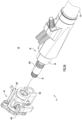
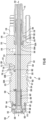
- FIGS. 4A and 4B depict the multi-diameter power pin 500 of the plug 50 with the torch cable 114 omitted for clarity.
- the power pin 500 is configured to receive arc process power (e.g., a weld or plasma cutting current), shield gases, arc process gases, and/or cooling fluid from the receiving block 400.
- the power pin 500 is further configured to receive weld wire from the feeder 230.
- a central bore 550 extends through the length of the power pin 500 along a longitudinal axis 501.
- the central bore 550 provides a path through the power pin 500 for process and/or shield gases and weld wire.
- a liner 600 is disposed within the central bore 550.
- the liner 600 comprises an elongated tube defining a conduit 602 for receiving the weld wire. Accordingly, the liner 600 isolates the weld wire from the inner surface of the power pin 500 and process and/or shield gasses flowing through the central bore 550.
- the power pin 500 includes a proximal portion 510, an engagement portion 520 extending from the proximal portion 510, a bearing portion 530 extending from the engagement portion 520, and a threaded distal portion 540 extending from the bearing portion 530.
- the proximal portion 510 of the power pin 510 has a diameter d.
- the engagement portion 520 as a diameter d1 smaller than diameter d of the proximal portion 510.
- the bearing portion 530 has a diameter d2 smaller than diameter d1 of the engagement portion 520.
- the threaded distal portion 540 has a diameter d3 smaller than diameter d2 of the bearing portion 530.
- the proximal portion 510 is configured to attach to the torch cable 114 (See FIG. 3A ).
- a distal end 514 of the proximal portion 510 includes an annular face 512, and a proximal end 516 includes an end face 517 with one or more fluid ports 518 which, in turn, are fluidly coupled to the central bore 550 via internal channels 519. Air may be blown through the fluid ports 518 to blow out any fluids and clean the internal channels 519 and central bore 550. Additionally, or alternatively, cooling fluid may flow through one or more of the internal channels 519 and the ports 518 to cool the torch 112.
- the end face 517 further includes a central bore inlet 552 configured to receive a cable adapter 554.
- the bore inlet 552 has a larger diameter than the central bore 550.
- the cable adapter 554 is a cylindrical tube that electrically and fluidly couples the power pin 500 and central bore 550 to a cable conductor 115. That is, the cable adapter 554 is configured to receive arc process power (e.g., a weld current) and gas from the power pin 500, and transfer the arc process power and gas to the cable conductor 115.
- the liner 600 extends through the cable adapter 554 and cable conductor 115.
- the adapter 554 further includes a seal 806 disposed between an inner surface 552A of the bore inlet 552 and an outer surface 554A of the cable adaptor 554 to prevent fluids from leaking through the bore inlet 552.
- the engagement portion 520 includes a distal end 521, a proximal end 522, an annular face 523 at the distal end 521, and an outer surface 524.
- the annular face 523 is angled with respect to the longitudinal axis 501 of the power pin 500. That is, the annular face 523 is oblique to the longitudinal axis 501 and/or the outer surface 524 of the engagement portion 520 to soften the transition from the engagement portion 520 to the bearing portion 530 (e.g., to form a ramped surface).
- the engagement portion 520 also includes an annular groove 525 that extends radially inward from the outer surface 524.
- the annular groove 525 is fluidly coupled to the central bore 550 by one or more radial channels 527.
- a process gas and/or shield gas may flow through the annular groove 525 and radial channels 527 to the central bore 550.
- the annular groove 525 is bounded by a first annular seal seat 526A and a second annular seal seat 526B, each of which extend radially inward from the outer surface 524 and receive a seal 802.
- first annular seal seat 526A is disposed between the distal end 521 of the engagement portion 520 and the annular groove 525 while the second annular seal seat 526B is disposed between the proximal end 522 of the engagement portion 520 and the annular groove 525.
- first annular seal seat 526A is disposed upstream from the annular groove 525 and the second annular seal seat is disposed downstream of the annular groove 525.
- the engagement portion 520 further includes one or more radial bores 528 with one or more engagement mechanisms 700 disposed therein (e.g., one mechanism 700 per bore 528).
- Each engagement mechanism 700 is configured to engage an inner surface of the receiving block 400 of the socket 40 and provisionally hold the power pin 500 in place. That is, when the plug 50 is inserted into the socket 40, the engagement mechanism 700 prevents the power pin 500 from sliding out of the receiving block 400.
- the engagement mechanism 700 comprises a ball 710 and spring 720 disposed in the radial bore 528.
- the spring 720 is disposed radially inward of the ball 710 and exerts a radial outward force on the ball 710.
- the radial outward force causes a portion of the ball 710 to extend past the outer surface 524 of the engagement portion 520 by a desired distance.
- the engagement mechanism 700 may further include a radial stop 712 to prevent the portion of the ball 710 from extending beyond the desired distance from the outer surface 524, and/or completely exiting the radial bore 528.
- the ball 710 is capable of translating completely within the radial bore 528 if a radially inward force, greater than the radial outward force from the spring, is applied to the ball 710. That is, a portion of the ball 710 extending past the outer surface 524 may be pushed into radial bore 528 such that a portion of the ball 710 does not radially extend beyond the outer surface 524.
- forces applied in a direction perpendicular to the radial force from the spring i.e., forces acting axially with respect to the power pin
- the plug 50 may be prevented from translating along the longitudinal axis 501.
- embodiments are not limited to an engagement mechanism 700 having a ball 710 and spring 720 configuration.
- the engagement mechanism 700 may be a resilient member radially extending from the outer surface 524 of the engagement portion 520.
- the engagement mechanism 700 may include an annular protrusion extending from the outer surface 524.
- the engagement mechanism may be a metal, a plastic, and/or a rubber ring disposed in a second annular groove in the outer surface 524.
- the engagement portion 520 may include a second annular groove configured to receive an engagement mechanism disposed in the central bore 402 of the receiving block 400.
- the bearing portion 530 of the power pin 500 is configured to be clamped by the receiving block 400.
- the bearing portion 530 is dedicated to providing a large contact area, free of obstructions, for clamping by the receiving block 400.
- the bearing portion 530 includes distal end 532, a proximal end 534, and a smooth outer surface or bearing surface 536 disposed therebetween. Said another way, the outer surface 536 does not include any surface protrusions or depressions.
- the smooth outer surface 536 provides consistent contact between the bearing portion 530 and an inner surface of the receiving block 400 in the clamped configuration C3. The consistent contact provides even clamping force along the bearing portion 530 and allows for efficient transmission of electricity between the receiving block 400 and power pin 500; thus reducing power losses.
- the distal threaded portion 540 is configured to receive and secure the liner 600 with a liner cap 610.
- the distal threaded portion 540 includes a first annular face a distal end 542, a proximal end 544, a threaded outer surface 546, and a distal annular face 548 disposed at the distal end 542.
- the central bore 550 extends through the distal annular face 548 and receives the liner 600.
- the threaded liner cap 610 is disposed over a tip 620 of the liner 600 and the distal threaded portion 540.
- the distal threaded portion 540, the liner 600, the liner cap 610 and liner tip 620 are concentrically arranged about longitudinal axis 501.
- the distal threaded portion 540 and the liner cap 610 cooperate to hold the liner tip 620 and liner 600 in place.
- the liner cap 610 includes a top wall 611 having an annular face 611A and a circumferential sidewall 612 having an outer surface 612A and an inner surface 612B.
- the liner cap 610 further includes a chamfered surface 613 between the annular face 611A and the outer surface 612A. The chamfered surface 613 helps guide the power pin 500 into the central bore 402 of the receiving block 400.
- the liner cap 610 further includes a first cavity portion 614A and second cavity portion 614B.
- the inner surface 612B of the sidewall 612 defines the first cavity portion 614A, and inner surfaces 611B and 611C define the second cavity portion 614B.
- the first cavity portion 614A is configured to receive the distal threaded portion 540 of the power pin 500.
- the inner surface 612B is threaded and configured to engage the threaded outer surface 546 of the threaded portion 540 of the power pin 500.
- the second cavity portion 614B is configured to accommodate a portion of the liner tip 620 when the cap 610 is coupled to the threaded portion 540 and has a smaller diameter than a diameter of the first cavity portion 614A. Accordingly, a user may unscrew the cap 610 to access threaded portion 540, the liner 600 and liner tip 620 for maintenance and/or to replace the liner 600 and liner tip 620.
- the liner cap 610 further includes a cap inlet 615 disposed in the top wall 611.
- the cap inlet 615 has a frustoconical shape defined by a cap inlet surface 615A.
- the frustoconical cap inlet 615 transitions to an expanding outlet 616 defined by outlet surface 616A.
- the cap inlet 615 and outlet 616 are fluidly coupled to the second cavity portion 614B. That is, the cap inlet 615 and outlet 616 provide a passage through the top wall 611 to the second cavity portion 614B.
- the liner tip 620 includes a distal end 622, a proximal end 624, and an elongate member, or ferrule, 625 extending from the distal end 622 to the proximal end 624.
- the elongate member 625 includes an inner surface 626 that defines a channel 628 for receiving a portion of the liner 600.
- the distal end 622 has a larger diameter than diameters of the elongate member 625 and of the central bore 550.
- the difference in diameters between the distal end 622 and the elongate member 625 defines a first annular face 6222.
- the first annular face 6222 is configured to abut the distal annular face 548 of the distal threaded portion 540. Consequently, the distal end 622 of the tip 620 is prevented from passing through the bore 550.
- the distal end 622 further includes a second annular face 6224 opposite the first annular face 6222 and a tip inlet 6202.
- the tip inlet 6202 has a frustoconical portion 6204 defined by a tip inlet inner surface 6204A, and a bore portion 6206 having substantially constant diameter defined by bore inner surface 6206A.
- the inlet 6202 is fluidly coupled to the conduit 602 of the liner 600.
- the liner 600 and tip elongate member 625 are inserted into the central bore 550 through the distal threaded portion 540 of the power pin 500.
- the first annular face 6222 of the distal end 622 of the liner tip 620 abuts the distal annular face 548 of the threaded portion 540 and prevents the liner tip 620 from passing completely through the bore 550.
- the liner cap 610 cooperates with the distal threaded portion 540 of the power pin 500 to secure the liner 600 and liner tip 620 in place. That is, the liner cap 610 receives the threaded portion 540 in the first cavity portion 614A and receives the distal end 622 of the liner tip 620 in the second cavity portion 614B.
- distal annular face 548 of the threaded portion 540 and the inner surfaces 611B and 611C of the second cavity portion 614B confine the distal end 622 of the liner tip 620.
- distal annular face 548 can bear against the first annular face 6222 of the distal end 622
- inner surface 611C of the cap 610 can bear against the second annular face 6224.
- the threaded inner surface 612B of cap sidewall 612 engages the outer threaded surface 546 to secure the liner cap 610 to threaded portion 540 of the power pin 500.
- threads disposed on the inner surface 612B engage threads of the outer surface 546.
- the distal end 622 is restrained between the distal threaded portion 540 and the liner cap 610, securing the liner tip 620 to the distal threaded portion 540. Because the liner 600 is secured to an inner surface 626 of the elongate member 625 of the liner tip 620, the liner 600 is also secured in place.
- the receiving block 400 includes a multi-diameter central bore 402 extending along a longitudinal axis 401 of the receiving block 400 that is configured to receive the multi-diameter power pin 500.
- the receiving block 400 also includes receiver portion 420, a dedicated clamping portion 430, a distal portion 440, and a quick release bolt 450 operatively coupled to the clamping portion 430.
- the receiving block 400 includes a U-shaped coupler 460 extending from a bottom of receiver portion 420 and clamping portion 430 that is configured to receive the arc process power conductor 240.
- the multi-diameter central bore 402 extends through the receiver portion 420, the clamping portion 430, and the distal portion 440.
- the central bore 402 has a diameter D1 through the receiver portion 420, a variable diameter D2 through the clamping portion 430 and a diameter D3 through the distal portion 440.
- D3 is less than diameter D1 while D2 is adjustable to a diameter that is also less than D1.
- Diameter D2 is varied by tightening of the quick release bolt 450 coupled to the clamping portion 430. The arrangement between the quick release bolt 450 and clamping portion 430 are discussed below.
- the receiver portion 420 includes a bore inlet 402A defining a lateral annular face 421A of the receiving block 400.
- the bore inlet 402A has a frustoconical shape defined by a receiver inlet surface 421B.
- An inner surface 420A of the receiver portion 420 defines a receiver bore section 402B of the central bore 402 having a diameter D1.
- a first annular groove 422 (configured to receive the engagement mechanism 700 of the engagement portion 520) and second annular groove 424 (configured to cooperate with the annular groove 525 of the engagement portion 520 to define a passageway for arc process gases) extend radially outward from the inner surface 420A.
- the first annular groove 422 has a curved surface 422A.
- a fluid channel 426 extends radially outward from the second annular groove 424 and ultimately to an external surface of the receiving block 400. The fluid channel 426 fluidly couples the second annular groove 424 to a fluid supply of the feeder assembly 20.
- the receiving portion 420 further defines a frustoconical receiver outlet 428 of the receiver bore section 402B opposite the bore inlet 402A.
- the receiver outlet 428 is defined by an outlet surface 428A extending radially inwards and axially towards the clamping portion 430. Said another way, a diameter of a section of the central bore 402 decreases along the receiver outlet 428 toward the clamping portion 430.
- the clamping portion 430 includes an inner surface 430A defining a clamping bore section 402C.
- the clamping portion 430 includes a first radial gap 432A, a second radial gap 432B parallel to the first radial gap 432A, and a third radial gap 434 extending from the first radial gap 432A to the second radial gap 432B.
- the first, second and third radial gaps 432A, 432B, and 434 extend radially from the clamping bore section 402C to one or more outer surfaces of the receiving block 400.
- the first, second, and third radial gaps 432A, 432B, and 434 define a resilient finger 436 having an upper portion 436A that receives a quick release bolt 450.
- the upper portion 436A can translate through the third radial gap 434 in response to a force received from the quick release bolt 450. That is, a length of the third radial gap 434 can be varied in response to loosening or tightening of the quick release bolt 450. For example, tightening the quick release bolt 450 decreases the length of the third radial gap 434 and the diameter D2 of the clamping bore section 402C. Conversely, loosening the quick release bolt 450 increases the length of the third radial gap 434 and increases the diameter D2 of the clamping bore section 402C. Consequently, the diameter D2 of the clamping bore section 402C is variable based on the force applied by the quick release bolt 450.
- the quick release bolt 450 is disposed in a laterally extending bore 438 that extends from an outer surface of upper portion 436A of the finger 436 and into the clamping portion 430 of the receiving block 400.
- the quick release bolt 450 includes a handle 4500 and a bolt 4520.
- the handle 4500 includes a proximal end 4502 and a distal end 4504.
- the proximal end 4502 includes a cam 4506.
- the bolt 4520 includes a proximal end 4522 rotatably coupled to the proximal end 4502 of the handle 4500, and a threaded distal end 4524 for engaging threads of the lateral bore 438.
- the quick release bolt 450 is merely an example of a tightening mechanism that may act on clamping portion 430 (and particularly on finger 436) to lock a power pin 500 in the receiving block 400.
- the quick release bolt 450 can be screwed into the lateral bore 438 with the handle 4500 in a released position (e.g., configuration C2 shown in FIG. 3C ). Additional force may be applied to the finger 436 by rotating the handle from the released position to the clamped position (e.g., configuration C3 shown in FIG. 3D ). Rotating the handle 4500 causes the cam 4506 to apply additional force to the finger 436 and decrease the lateral length of the gap 434. Accordingly, the finger 436 can translate in response to the handle 4500 rotating from the clamped position to the released position and/or from the released position to the clamped portion.
- this tightening is merely an example and in other embodiments any tightening mechanism may be tightened in any manner now known or developed hereafter.
- the distal portion 440 of the receiving block 400 includes an inner surface 440A defining a distal bore section 402D having a diameter D3.
- the diameter D3 of the distal bore section 402D is less than the diameter D1 of the receiver bore section 402B.
- the distal bore section 402D is configured to receive the distal portion 540 of the power pin 500.
- the U-shaped coupler 460 extending from a bottom of receiver portion 420 and clamping portion 430 receives the arc process power conductor 240.
- the coupler 460 includes a main body section 461 and a clamping section 462 having an inner surface 463 that defines a longitudinally extending receiving bore 464 configured to receive the conductor 240. That is, the receiving bore 464 extends in a direction parallel to, and radially offset from, the longitudinal axis 401 of the receiving block 400 to receive the conductor 240.
- the coupler 460 might have a different shape or position that define the receiving bore 464 in a different configuration.
- a radial gap 467 between the main body section 461 and the clamping section 462 extends radially upward from the receiving bore 464.
- a first through hole 465A extends laterally through the main body section 461, and a second through hole 465B, coaxial with the firsts through hole 465A, extends laterally through the clamping section 462.
- the first and second through holes 465A, 465B receive a clamping bolt 466.
- the clamping bolt 466 applies a force to pull the clamping section 462 towards the main body section 461 until the inner surface 463 of the coupler 460 contacts and bears against an outer surface 242 of the conductor 240 thereby securing the conductor 240 within the receiving bore 464. Accordingly, the conductor 240 is secured and electrically coupled to the coupler 460, and thus, the receiving block 400.
- this is merely an example and other embodiments may secure the conductor 240 to the coupler 460 in any desired manner.
- FIG. 7 a cross-sectional view of the connector 30 with the multi-diameter power pin 500 and the arc process power conductor 240 inserted into the receiving block 400 is shown.
- the connector 30 is shown in the third configuration C3 with power pin 500 clamped to the receiving block 400.
- the engagement portion 520 is axially aligned with and accommodated within the receiving portion 420
- the bearing portion 530 is axially aligned with and accommodated within the clamping portion 430
- the threaded distal portion 540 is axially aligned with and accommodated within the distal portion 440.
- the diameter D1 of the receiver bore section 420B see FIG.
- variable diameter D2 of the clamping bore section 402C and diameter D3 of the distal portion 440 is slightly larger than diameter d2 of the bearing portion 530 and diameter d3 of the distal threaded portion 540, respectively (see FIGS. 4B and 6D ).
- the receiver portion 420 abuts the proximal portion 510 of the power pin 500 to axially align each portion of the power pin 500 with each corresponding portion of the receiving block 400. That is, the annular face 512 of the proximal portion 510 faces and abuts the lateral annular face 421A of the receiver portion 420. With the power pin 500 aligned with the receiving block 400, the second annular groove 424 of the portion 420 cooperates with the annular groove 525 of the engagement portion 520 to form an annular fluid channel 800. Additionally, the engagement mechanism 700 engages the first annular groove 422 of the receiver portion 420 to provisionally hold the power pin 500 in the central bore 402.
- the spring 720 of the engagement mechanism 700 pushes a portion of the ball 710 into the first annular groove 422.
- the ball 710 and first annular groove 422 prevent axial movement of the power pin 500, unless a radial force sufficient to overcome the force from the spring 720 is applied to the ball 710.
- An axial force may be transferred through the power pin 500 to the ball 710 which bears against a portion of the first annular groove 422.
- a portion of the axial force can be converted into a radial force in response to the ball 710 bearing against the curved surface 422A of the first annular groove 422.
- the connector 30 is moved out of its third configuration C3 (e.g., to configuration C2) a user can disengage the engagement mechanism 700 by pulling with sufficient axial force such that the curved surface 422A converts the axial force into a radial force greater than the spring force.
- the engagement portion 520 may include a plurality of engagement mechanisms 700.
- the engagement portion 520 may include two, three, four, or more engagement mechanisms 700 to engage the first annular groove 422 of the receiver portion 420.
- the engagement mechanism 700 may be a resilient annular ring that protrudes from or is disposed on the engagement portion 520.
- the engagement mechanism may be a plastic, metal, and/or rubber ring secured to the engagement portion 520.
- the engagement mechanism 700 may be a protrusion extending from the outer surface 524 of the engagement portion 520.
- one or more engagement mechanisms 700 may be disposed in the receiver portion 420 and the first annular groove 422 may be disposed at the engagement portion 520.
- the receiver portion 420 fluidly couples the feeder 20 to the torch cable 114 via the engagement portion 520.
- fluid channel 426, the annular fluid channel 800 (e.g., annular grooves 424 and 525), the internal channels 519, the pin central bore 550, and the cable conductor 115 form a fluid passageway from the wire feeder assembly 20 to the torch 112.
- the seals 802 disposed in the first and second annular seal seats 526A, 526B of the engagement portion 520 prevent leakage of the process gas from the annular fluid channel 800.
- An additional sealing means of the receiving portion 420 is provided by the annular face 523 butting the outlet surface 428A and the annular face 512 abutting the lateral annular face 421A.
- seals 806 prevent the process gas from leaking past the cable adapter 554, and seals 807 and 808 prevent process gas from leaking past the liner cap 610 and liner tip 620, respectively.
- the seals 802, 806, 807, 808 may be O-rings.
- a user may clamp the clamping portion 430 to the bearing portion 530 using the quick release bolt 450 (see FIGS. 3C-3D ) to place the connector 30 into its clamped configuration C3.
- the bearing surface 536 does not include any surface features that obstructs contact of the inner surface 430A to the bearing surface 536. Therefore, the finger 436 can effectively clamp the bearing portion 530 in place, and secure the plug 50 in the socket 40.
- the contact between the inner surface 430A and the bearing surface 536 electrically couples the receiving block 400 to the power pin 500.
- power from the conductor 240 is conducted through the receiving block 400 to the power pin 500 and then conducted through the cable adapter 554 to the cable conductor 115.
- an electric current is conducted from the conductor 240 to the U-shaped coupler 460, through the receiving block 400 where the electricity is conducted from inner surface 430A to the bearing surface 536 of bearing portion 530.
- the current is then conducted through the cable adapter 554 and the cable conductor 115 to the torch 112.
- process gas flows from the wire feeder assembly 20 through fluid channel 426 into the annular fluid channel 800.
- the process gas then passes through pin internal channels 519, the pin central bore 550, the cable adapter 554, and the cable conductor 115 to the torch 112.
- a weld wire is guided through the power pin 500 and torch cable 114 to the torch 112.
- weld wire is pulled from a wire supply 140 by wire rollers 232 and is isolated from electrical currents and process gases by the liner 600.
- a wire guide 900 supported in the feeder assembly 20 by a guide support 910, receives the weld wire from the wire rollers 232 and guides the weld wire to the multi-diameter central bore 402.
- the distal threaded portion 540 with liner cap 610 and the cap inlet 615 are radially aligned with the wire guide 900.
- the weld wire enters the cap 610 via the cap inlet 615.
- the cap inlet surface 615A guides the weld wire radially inwards and towards the liner tip inlet 6202.
- the tip inlet inner surface 6204A guides the weld wire radially inwards and towards the liner conduit 602. Both the cap inlet surface 615A and the tip inlet inner surface 6204A prevent kinking and/or jamming of the weld wire after it exits the wire guide 900.
- the liner 600 (which extends through the torch cable 114 to the torch 112) guides the weld wire to the torch 112 where it is consumed in an arc welding process.
- the liner 600, liner cap 610, and liner tip 620 isolate weld wire received in the conduit 602 from gas flowing through the power pin 500 and from contacting the inner surface of the power pin 500 defining the central bore 550.
- FIGS. 8A and 8B a receiving block 1400 according to a second embodiment is shown.
- the receiving block 1400 is similar to receiving block 400, except the clamping bolt 466 for clamping the conductor 240 is replaced with a quick release bolt 1466 similar to quick release bolt 450.
- the configuration of receiving block's clamping portion and U-shaped conductor connector are adjusted to accommodate the quick release bolt 1466. For brevity, only the differences between receiving block 400 and receiving block 1400 are discussed.
- the receiving block 1400 includes a receiver portion 1420, a clamping portion 1430, a distal portion 1440, and a U-shaped conductor coupler 1460.
- the U-shaped conductor coupler 1460 includes a main body section 1461 that extends from a bottom of the receiving block 1400 downwardly at an angle with respect to a vertical axis 1401.
- a clamping portion 1462 extends upwards from the main body section 1461 to define a longitudinally extending receiving bore 1464.
- a first through hole 1465A extends laterally through the main body section 1461, and a second through hole 1465B, coaxial with the firsts through hole 1465A, extends laterally through the clamping section 1462.
- the first and second through holes 465A, 465B receive a quick release bolt 1466.
- the first and second through holes 465A, 465B extend at an oblique angle with respect to the vertical axis 1401.
- the quick release bolt 1466 applies a force to pull the clamping section 1462 towards the main body section 1461 until an inner surface 1463 of the coupler 1460 contacts and bears against an outer surface 242 of the conductor 240 thereby securing the conductor 240 within the receiving bore 1464. Accordingly, the conductor 240 is secured and electrically coupled to the U-shaped conductor coupler 1460, and thus, the receiving block 1400.
- the clamping portion 1430 includes an inner surface 1430A for engaging the power pin 500.
- the clamping portion 1430 includes a first radial gap 1432A, a second radial gap 1432B parallel to the first radial gap 1432A.
- the first and second radial gaps 1432A, 1432B extend perpendicularly with respect to the vertical axis 1401.
- a third radial gap 1434 extends from the first radial gap 1432A to the second radial gap 1432B.
- the first, second and third radial gaps 1432A, 1432B, and 1434 extend radially from the inner surface 1430A to one or more outer surfaces of the receiving block 1400.
- first, second, and third radial gaps 1432A, 1432B, and 1434 define a resilient finger 1436 having a lateral portion 1436A that receives a quick release bolt 450.
- the resilient finger 1436 extends in a direction substantially perpendicular to the vertical axis 1401.
- the quick release bolt 450 is disposed in a vertically extending bore 1438 that extends from an outer surface of the lateral portion 1436A of the finger 1436 and into the clamping portion 1430 of the receiving block 1400.
- the upper portion 1436A can translate through the third radial gap 1434 in response to a force received from the quick release bolt 450. That is, a length of the third radial gap 1434 can be varied in response to loosening or tightening of the quick release bolt 450. For example, tightening the quick release bolt 450 decreases the length of the third radial gap 1434. Conversely, loosening the quick release bolt 450 increases the length of the third radial gap 1434.
- the length of the third radial gap 1434 is variable based on the force applied by the quick release bolt 450.
- the quick release bolt 450 can be tightened and loosened to place the clamping portion 1430 between a clamped position (e.g., similar to configuration to C3 shown in FIG. 3D ) and a released position (e.g., similar to configuration C2 shown in FIG. 3C ).
- a connector 30 is presented in which the liner cap 610 and liner 600 can be easily installed, secured, and/or replaced without the drawbacks of the conventional liner and bolt arrangement noted above.
- a user can insert the power pin 500 into a receiving block 400, 1400 and provisionally lock the plug 50 with the engagement mechanism 700, let go of the torch cable 114, and clamp and secure the power pin 500 in place with the quick release bolt 450. Consequently, electricity and fluid may be efficiently transmitted from the receiving block 400, 1400 to the power pin 500 without the drawbacks of the conventional power pin noted above.
- the welding system 1 described herein, or portions thereof may be fabricated from any suitable material or combination of materials, such as plastic, foamed plastic, wood, cardboard, pressed paper, metal, supple natural or synthetic materials including, but not limited to, cotton, elastomers, polyester, plastic, rubber, derivatives thereof, and combinations thereof.
- Suitable plastics may include high-density polyethylene (HDPE), low-density polyethylene (LDPE), polystyrene, acrylonitrile butadiene styrene (ABS), polycarbonate, polyethylene terephthalate (PET), polypropylene, ethylene-vinyl acetate (EVA), or the like.
- Suitable foamed plastics may include expanded or extruded polystyrene, expanded or extruded polypropylene, EVA foam, derivatives thereof, and combinations thereof.
- upstream and downstream are considered in relation to a path of the weld wire (e.g., from the wire guide 900 to the cable conductor 115 in FIG. 7 ).
Landscapes
- Engineering & Computer Science (AREA)
- Physics & Mathematics (AREA)
- Plasma & Fusion (AREA)
- Mechanical Engineering (AREA)
- Connector Housings Or Holding Contact Members (AREA)
Description
- The present invention relates to the field of electrical connections and, in particular, a multi-diameter power pin for a plug of a cable for an arc process system, and a socket for a multi-diameter power pin of a plug of a cable for an arc process system according to the preamble of
claims 1 and 9 (see for exampleGB 1,036,804A - Generally, welding robots include one or more arms, a torch, and a wire feeder for feeding weld wire to the torch. The torch is disposed at a distal end of the robot and the wire feeder is disposed between a base of the torch and the distal end. A cable connects the wire feeder to the torch and provides one or more of electricity, weld wire, process gas, and cooling fluid from the wire feeder. Close contact between a power pin of the plug and receiving block of a socket is desirable for proper transfer of electricity and fluids from the wire feeder to the torch cable.
- Typically, a user climbs up the robot to connect the torch cable to the wire feeder. The user inserts a plug of the torch cable into a socket of the wire feeder and holds it in place with one hand, while clamping the plug to a socket with the other hand. With both hands otherwise occupied with clamping/securing the torch cable to the wire feeder, the user does not have a free hand to steady herself while perched on the robot. The user may be unsteady on the robot and could fall off. Consequently, the user may not properly secure the plug of the cable with the socket resulting in inefficient transfer of electricity, kinking or jamming of weld wire, and/or leakage of fluids.
- Moreover, typically, a liner is disposed in the plug and cable to protect weld wire fed through the connector. The liner can be installed in the cable by inserting the liner through the power pin of the plug. Once installed, the liner isolates weld wire from the electrical current and/or a fluid that flows through the power pin and cable. Often, the liner is held in place by a bolt that traverses the power pin and engages a tip of the liner. The bolt may be loosened or tightened with a tool, e.g., screw driver, allen wrench, etc., but over tightening of the bolt may cause damage to the liner, which may cause the weld wire to kink.
- A plug assembly for an arc process device is disclosed in
US 7,274,001B1 . The plug assembly has a metal plug portion for electrically coupling to a welding machine. The plug portion extends from an insulated rear case that is coupled to a cable hose. A socket conveying electrical current, shield gas, and compressed air for an arc processing device is disclosed inGB 1,036,804A - In view of at least the aforementioned issues, a connection system for efficiently and safely securing a liner within a torch cable, and/or connecting a torch cable to a power source and/or wire feeder are desirable.
- According to a first aspect of the present invention, a multi-diameter power pin for a plug of a cable for an arc process system is defined in
claim 1. - Further preferred embodiments of the power pin are defined in the corresponding dependent claims.
- According to a second aspect of the present invention, a socket for a multi-diameter power pin of a plug of a cable for an arc process system is defined in claim 9.
- Further preferred embodiments of the socket are defined in the corresponding dependent claims.
- To complete the description and in order to provide for a better understanding of the present invention, a set of drawings is provided. The drawings form an integral part of the description and illustrate an embodiment of the present invention, which should not be interpreted as restricting the scope of the invention, but just as an example of how the invention can be carried out. The drawings comprise the following figures:
-
FIG. 1 is a schematic diagram of a robot welding system, according to an exemplary embodiment. -
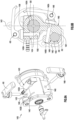
FIG. 2A is a perspective view of a wire feeder assembly with a partially transparent housing, according to an embodiment. -
FIG. 2B is a perspective internal view of a portion of the wire feeder assembly of claim 2A, according to an embodiment. -
FIGS. 3A and3B are perspective views of a connector in a first configuration, according to an embodiment. -
FIG. 3C is a cross-sectional view of the connector ofFIGS. 3A and3B in a second configuration, according to an embodiment. -
FIG. 3D is a cross-sectional view of the connector ofFIGS. 3A and3B in a third configuration, according to an embodiment. -
FIG. 4A is a perspective view of a power pin, according to an embodiment. -
FIG. 4B is a cross-sectional view of the power pin ofFIG. 4A . -
FIG. 5 is a cross-sectional view of the distal end of the power pin ofFIG. 4A during installation into a plug. -
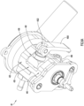
FIG. 6A is a perspective view of the socket according to an embodiment. -
FIG. 6B is a side view of the socket ofFIG. 6A . -
FIG. 6C is a cross-sectional view of the socket taken along line A-A ofFIG. 6B . -
FIG. 6D is a cross-sectional view of a receiving block of the socket taken along line B-B ofFIG. 6B . -
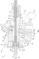
FIG. 7 is a cross-sectional view of the connector in the third configuration. -
FIG. 8A is a front perspective view of a receiving block according to a second embodiment. -
FIG. 8B is a cross-sectional view of the receiving block ofFIG. 8A . - The following description is not to be taken in a limiting sense but is given solely for the purpose of describing the broad principles of the invention. Embodiments of the invention will be described by way of example, with reference to the above-mentioned drawings showing elements and results according to the present invention. Embodiments of the invention are described with reference to a connector for a wire feeder and a welding torch cable, however embodiments are not limited thereto. For example, the connector may be used for connecting and transmitting power between any two components of a high-power system, such as a power source and a cable of a plasma cutting torch.
- A conventional power pin of a plug for an arc processing operation (e.g., a welding or plasma cutting operation) generally includes only one or two portions having one or two diameters. For example, a conventional power pin may include an attachment portion for attaching to a cable and a second portion configured to be clamped into and receive one or more gases from a receiving block of a socket. Typically, the entire second portion is clamped in receiving block. That is, a clamp of the receiving block is configured to bear against of the second portion. The second portion generally includes surface features, such as one or more grooves, bores, and/or protrusions configured to receive one or more of process gases, seals, holder screws, etc.
- When the conventional power pin is inserted into a receiving block of a socket, a user must hold the plug in place with one hand and clamp the second portion in the receiving block with a second hand. However, if one or more of surface features of the second portion are not be properly aligned with corresponding structures in the receiving block during this two-handed clamping operations, fluids used during the arc processing operation may leak from the plug and socket. Moreover, even if the second portion is properly aligned within the receiving block, one or more of the surface features may obstruct the clamp of the receiving block resulting in a loose connection between the power pin and receiving block. The loose connection may allow the plug to fall out and/or cause a poor electrical connection, resulting in power losses during operation.
- Generally, the system and method for connecting a torch cable to a wire feeder presented herein include a plug having a multi-diameter power pin and a socket with a receiving block having a multi-diameter through hole, or bore, for receiving the power pin. The features of the power pin and receiving block allow a user to connect and secure the plug to the socket with one hand. For example, an engagement mechanism disposed in the power pin engages an inner surface of the receiving block in response to inserting the pin into the receiving block. The engagement mechanism maintains a position of the power pin while the user clamps and secures the power pin in the receiving block. Thus, with one hand, the user can insert the power pin into the receiving block and provisionally lock it with the engagement mechanism, let go of the torch cable, and lock the power pin in place with a clamp.
- Moreover, a dedicated bearing portion of the power pin corresponding to dedicated clamping portion of the receiving block provides an improved electrical connection between the pin and receiving block as compared to conventional connectors. That is, the dedicated bearing portion and clamp provide unobstructed contact between the power pin and receiving block. Thus, electricity may be efficiently conducted between the receiving block and power pin without the drawbacks of the conventional power pin noted above.
- Additionally, the power pin includes a central bore for receiving a liner that extends into the torch cable. The liner isolates a weld wire passing through the connector from an inner surface of the power pin and a conductor of the torch cable. A user can access the central bore of the power pin by removing a liner cap by hand, without using a tool, and insert the liner with the liner tip into the central bore. To secure the liner, the user can dispose the liner cap over the liner tip and a distal portion of the power pin, thereby clamping the liner tip between the liner cap and power pin. To access or replace the liner, a user can remove the liner cap, without a tool, to expose the liner tip and distal end of the power pin. Thus, the liner cap and liner can be easily installed, secured, and/or replaced without the drawbacks of the conventional liner and bolt arrangement noted above. Moreover, the liner cap shape assists in guiding the power pin into the receiving block and prevents weld wire from kinking.
- Referring to
FIG. 1 , a schematic diagram of an exemplary embodiment of arobot welding system 1, according to an embodiment is depicted. Therobot welding system 1 includes arobot 10 connected to acontroller 110, awire feeder assembly 20, apower source 130, andwire spool 140. Thepower source 130 is electrically coupled to therobot 10 and thetorch 112 via thecontroller 110, and thewire feeder assembly 20, respectively. Thepower source 130 can provide power to components of therobot 10,controller 110, and thewire feeder assembly 20, as well as a process current for an arc process (e.g., a welding or plasma cutting operation). Additionally, thepower source 130 may provide a shield gas and/or a process gas for the plasma arc process to the wire feeder. Thecontroller 110 controls the movement of therobot 10 and the plasma arc process. Awire supply 140 provides weld wire to thewire feeder assembly 20. Thewire supply 140 may be abulk pack 142 or aspool 144. In some implementations, thespool 144 is disposed in thewire feeder assembly 20. - In the depicted embodiment, the
robot 10 includes abase 100, afirst arm 102 pivotably attached to and extending from thebase 100, and asecond arm 104 pivotably coupled to thefirst arm 102, opposite thebase 100. Atorch 112 is disposed on adistal end 106 of thesecond arm 104, and thewire feeder assembly 20 is disposed at a coupling between thefirst arm 102 andsecond arm 104. However, this is just one example of a welding robot and the present application may be applicable to a wide variety of robots. - Regardless of the exact configuration of the robot and the location of the
wire feeder assembly 20 on the robot, atorch cable 114 connects thetorch 112 to thewire feeder assembly 20. Aconnector 30 couples thetorch cable 114 to thewire feeder assembly 20. The connector includes asocket 40 disposed at the wire feeder assembly 20 (seeFIG. 2A ) and aplug 50 disposed on the torch cable 114 (seeFIGS. 3A-3B ). During a weld operation, thetorch cable 114 transmits a process current, weld wire, and fluids (e.g., shield gas, process gas, and/or cooling fluid) from thewire feeder assembly 20 through theconnector 30 andtorch cable 114 to thetorch 112. -
FIG. 2A is a side perspective view of awire feeder assembly 20 according to an embodiment. Thewire feeder assembly 20 includes an outer housing 200 having afront face 210 and arear face 212. Thefront face 210 includes aconnector port 214 and apower port 216 that each define passageways through thefront face 210 to aninterior compartment 202 defined by the housing 200. Adivider wall 220 within the housing 200 divides theinterior compartment 202 into awire feeding side 204 and a control side 206. Thewire feeding side 204 houses asocket 40 of theconnector 30 and afeeder 230 for pulling weld wire through awire port 218 in therear face 212. Theconnector port 214 provides a passage for aplug 50 of theconnector 30 to be inserted into thesocket 40. A conductor 240 (SeeFIG. 7 ) for conducting arc process power can be inserted through thepower port 216 and electrically coupled to thesocket 40, as is described below with reference toFIGS. 6A-7 . - The
feeder 230 includes a plurality ofwire rollers 232 for pulling the weld wire from awire supply 140 through thewire port 218 and pushing the weld wire through thesocket 40. The control side 206 includes components and/or circuitry for receiving signals and controlling thefeeder 230 based on the received signals. In some implementations, the components and/or circuitry may control one or more arc process parameters (e.g., process power, process current, voltage, process gas flow, shield gas flow, cooling fluid flow, wire feed speed, etc.). -
FIG. 2B is a perspective view of a portion of thewire feeding side 204 of theinterior compartment 202. A receivingblock 400 of thesocket 40 is disposed between and aligned with thefeeder 230 and theconnector port 214. The receivingblock 400 is configured to receive theplug 50 of theconnector 30 and theconductor 240. - Referring to
FIGS. 3A - 3D , three configurations of theconnector 30 are illustrated. Thewire feeder assembly 20 accommodating thesocket 40 has been omitted for clarity. In configuration C1, theplug 50 is separate and removed from the socket 40 (seeFIGS. 3A and3B ). Theplug 50 of theconnector 30 includes adistal end 52 and aproximal end 54 connected to thetorch cable 114. Amulti-diameter power pin 500 is disposed at thedistal end 52. Thesocket 40 includes a receivingblock 400 having a multi-diameter through hole, or central bore, 402 for receiving thepower pin 500. - In configuration C2 the
plug 50 is inserted into thesocket 40 but is not clamped in place or otherwise locked (seeFIG. 3C ). Thepower pin 500 provisionally engages an internal surface of the receivingblock 400 defining thecentral bore 402 and holds theplug 50 in place. Consequently, theplug 50 cannot disengage thesocket 40 on its own, but a user can remove theplug 50 by hand, if desired. The provisional engagement configuration C2 between thepower pin 500 and receivingblock 400 is discussed in detail below with reference toFIG. 7 . - In configuration C3, the
socket 40 receives and clamps, or otherwise locks, theplug 50 in position with a quick release bolt 450 (seeFIG. 3D ). In the locked configuration C3, the receivingblock 400 secures thepower pin 500 in thecentral bore 402 such that theplug 50 cannot be removed from thesocket 40 without damaging the connector 30 (i.e., irremovably locks the connector 30). The locked configuration C3 between thepower pin 500 and receivingblock 400 is discussed in detail below with reference toFIG. 7 . -
FIGS. 4A and4B depict themulti-diameter power pin 500 of theplug 50 with thetorch cable 114 omitted for clarity. Thepower pin 500 is configured to receive arc process power (e.g., a weld or plasma cutting current), shield gases, arc process gases, and/or cooling fluid from the receivingblock 400. Thepower pin 500 is further configured to receive weld wire from thefeeder 230. Acentral bore 550 extends through the length of thepower pin 500 along alongitudinal axis 501. Thecentral bore 550 provides a path through thepower pin 500 for process and/or shield gases and weld wire. Aliner 600 is disposed within thecentral bore 550. Theliner 600 comprises an elongated tube defining aconduit 602 for receiving the weld wire. Accordingly, theliner 600 isolates the weld wire from the inner surface of thepower pin 500 and process and/or shield gasses flowing through thecentral bore 550. - The
power pin 500 includes aproximal portion 510, anengagement portion 520 extending from theproximal portion 510, a bearingportion 530 extending from theengagement portion 520, and a threadeddistal portion 540 extending from the bearingportion 530. Theproximal portion 510 of thepower pin 510 has a diameter d. Theengagement portion 520 as a diameter d1 smaller than diameter d of theproximal portion 510. The bearingportion 530 has a diameter d2 smaller than diameter d1 of theengagement portion 520. The threadeddistal portion 540 has a diameter d3 smaller than diameter d2 of the bearingportion 530. - The
proximal portion 510 is configured to attach to the torch cable 114 (SeeFIG. 3A ). Adistal end 514 of theproximal portion 510 includes anannular face 512, and aproximal end 516 includes anend face 517 with one or morefluid ports 518 which, in turn, are fluidly coupled to thecentral bore 550 viainternal channels 519. Air may be blown through thefluid ports 518 to blow out any fluids and clean theinternal channels 519 andcentral bore 550. Additionally, or alternatively, cooling fluid may flow through one or more of theinternal channels 519 and theports 518 to cool thetorch 112. - The
end face 517 further includes acentral bore inlet 552 configured to receive acable adapter 554. Thebore inlet 552 has a larger diameter than thecentral bore 550. Thecable adapter 554 is a cylindrical tube that electrically and fluidly couples thepower pin 500 andcentral bore 550 to acable conductor 115. That is, thecable adapter 554 is configured to receive arc process power (e.g., a weld current) and gas from thepower pin 500, and transfer the arc process power and gas to thecable conductor 115. Theliner 600 extends through thecable adapter 554 andcable conductor 115. Theadapter 554 further includes aseal 806 disposed between aninner surface 552A of thebore inlet 552 and anouter surface 554A of thecable adaptor 554 to prevent fluids from leaking through thebore inlet 552. - The
engagement portion 520 includes adistal end 521, aproximal end 522, anannular face 523 at thedistal end 521, and anouter surface 524. Theannular face 523 is angled with respect to thelongitudinal axis 501 of thepower pin 500. That is, theannular face 523 is oblique to thelongitudinal axis 501 and/or theouter surface 524 of theengagement portion 520 to soften the transition from theengagement portion 520 to the bearing portion 530 (e.g., to form a ramped surface). - The
engagement portion 520 also includes anannular groove 525 that extends radially inward from theouter surface 524. Theannular groove 525 is fluidly coupled to thecentral bore 550 by one or moreradial channels 527. A process gas and/or shield gas may flow through theannular groove 525 andradial channels 527 to thecentral bore 550. To prevent leakage, theannular groove 525 is bounded by a firstannular seal seat 526A and a secondannular seal seat 526B, each of which extend radially inward from theouter surface 524 and receive aseal 802. That is, the firstannular seal seat 526A is disposed between thedistal end 521 of theengagement portion 520 and theannular groove 525 while the secondannular seal seat 526B is disposed between theproximal end 522 of theengagement portion 520 and theannular groove 525. Put still another way, the firstannular seal seat 526A is disposed upstream from theannular groove 525 and the second annular seal seat is disposed downstream of theannular groove 525. - The
engagement portion 520 further includes one or more radial bores 528 with one ormore engagement mechanisms 700 disposed therein (e.g., onemechanism 700 per bore 528). Eachengagement mechanism 700 is configured to engage an inner surface of the receivingblock 400 of thesocket 40 and provisionally hold thepower pin 500 in place. That is, when theplug 50 is inserted into thesocket 40, theengagement mechanism 700 prevents thepower pin 500 from sliding out of the receivingblock 400. - In the depicted embodiment, the
engagement mechanism 700 comprises aball 710 andspring 720 disposed in theradial bore 528. Thespring 720 is disposed radially inward of theball 710 and exerts a radial outward force on theball 710. The radial outward force causes a portion of theball 710 to extend past theouter surface 524 of theengagement portion 520 by a desired distance. Theengagement mechanism 700 may further include aradial stop 712 to prevent the portion of theball 710 from extending beyond the desired distance from theouter surface 524, and/or completely exiting theradial bore 528. - The
ball 710 is capable of translating completely within the radial bore 528 if a radially inward force, greater than the radial outward force from the spring, is applied to theball 710. That is, a portion of theball 710 extending past theouter surface 524 may be pushed intoradial bore 528 such that a portion of theball 710 does not radially extend beyond theouter surface 524. However, forces applied in a direction perpendicular to the radial force from the spring (i.e., forces acting axially with respect to the power pin) may not cause theball 710 to translate into theradial bore 528. Thus, when theengagement mechanism 700 engages the receivingblock 400, theplug 50 may be prevented from translating along thelongitudinal axis 501. - That all said, embodiments are not limited to an
engagement mechanism 700 having aball 710 andspring 720 configuration. As an example, in some implementations, theengagement mechanism 700 may be a resilient member radially extending from theouter surface 524 of theengagement portion 520. Specifically, theengagement mechanism 700 may include an annular protrusion extending from theouter surface 524. As another example, the engagement mechanism may be a metal, a plastic, and/or a rubber ring disposed in a second annular groove in theouter surface 524. As yet another example, theengagement portion 520 may include a second annular groove configured to receive an engagement mechanism disposed in thecentral bore 402 of the receivingblock 400. - While the
engagement mechanism 700 is configured to engage the receivingblock 400, the bearingportion 530 of thepower pin 500 is configured to be clamped by the receivingblock 400. The bearingportion 530 is dedicated to providing a large contact area, free of obstructions, for clamping by the receivingblock 400. The bearingportion 530 includesdistal end 532, aproximal end 534, and a smooth outer surface or bearingsurface 536 disposed therebetween. Said another way, theouter surface 536 does not include any surface protrusions or depressions. The smoothouter surface 536 provides consistent contact between the bearingportion 530 and an inner surface of the receivingblock 400 in the clamped configuration C3. The consistent contact provides even clamping force along the bearingportion 530 and allows for efficient transmission of electricity between the receivingblock 400 andpower pin 500; thus reducing power losses. - Still referring to
FIGS. 4A and4B , the distal threadedportion 540 is configured to receive and secure theliner 600 with aliner cap 610. The distal threadedportion 540 includes a first annular face adistal end 542, aproximal end 544, a threadedouter surface 546, and a distalannular face 548 disposed at thedistal end 542. Thecentral bore 550 extends through the distalannular face 548 and receives theliner 600. The threadedliner cap 610 is disposed over atip 620 of theliner 600 and the distal threadedportion 540. The distal threadedportion 540, theliner 600, theliner cap 610 andliner tip 620 are concentrically arranged aboutlongitudinal axis 501. The distal threadedportion 540 and theliner cap 610 cooperate to hold theliner tip 620 andliner 600 in place. - Referring to
FIG. 5 , the configuration of theliner 600, theliner cap 610, theliner tip 620, and the distal threadedportion 540 of thepower pin 500 is depicted. Theliner cap 610 includes atop wall 611 having anannular face 611A and acircumferential sidewall 612 having anouter surface 612A and aninner surface 612B. Theliner cap 610 further includes a chamferedsurface 613 between theannular face 611A and theouter surface 612A. The chamferedsurface 613 helps guide thepower pin 500 into thecentral bore 402 of the receivingblock 400. - The
liner cap 610 further includes afirst cavity portion 614A andsecond cavity portion 614B. Theinner surface 612B of thesidewall 612 defines thefirst cavity portion 614A, andinner surfaces second cavity portion 614B. Thefirst cavity portion 614A is configured to receive the distal threadedportion 540 of thepower pin 500. Theinner surface 612B is threaded and configured to engage the threadedouter surface 546 of the threadedportion 540 of thepower pin 500. Thesecond cavity portion 614B is configured to accommodate a portion of theliner tip 620 when thecap 610 is coupled to the threadedportion 540 and has a smaller diameter than a diameter of thefirst cavity portion 614A. Accordingly, a user may unscrew thecap 610 to access threadedportion 540, theliner 600 andliner tip 620 for maintenance and/or to replace theliner 600 andliner tip 620. - The
liner cap 610 further includes acap inlet 615 disposed in thetop wall 611. Thecap inlet 615 has a frustoconical shape defined by acap inlet surface 615A. Thefrustoconical cap inlet 615 transitions to an expandingoutlet 616 defined byoutlet surface 616A. Thecap inlet 615 andoutlet 616 are fluidly coupled to thesecond cavity portion 614B. That is, thecap inlet 615 andoutlet 616 provide a passage through thetop wall 611 to thesecond cavity portion 614B. - The
liner tip 620 includes adistal end 622, aproximal end 624, and an elongate member, or ferrule, 625 extending from thedistal end 622 to theproximal end 624. Theelongate member 625 includes aninner surface 626 that defines achannel 628 for receiving a portion of theliner 600. Thedistal end 622 has a larger diameter than diameters of theelongate member 625 and of thecentral bore 550. The difference in diameters between thedistal end 622 and theelongate member 625 defines a firstannular face 6222. The firstannular face 6222 is configured to abut the distalannular face 548 of the distal threadedportion 540. Consequently, thedistal end 622 of thetip 620 is prevented from passing through thebore 550. - The
distal end 622 further includes a secondannular face 6224 opposite the firstannular face 6222 and atip inlet 6202. Thetip inlet 6202 has afrustoconical portion 6204 defined by a tip inletinner surface 6204A, and abore portion 6206 having substantially constant diameter defined by boreinner surface 6206A. Theinlet 6202 is fluidly coupled to theconduit 602 of theliner 600. - When assembled, the
liner 600 and tipelongate member 625 are inserted into thecentral bore 550 through the distal threadedportion 540 of thepower pin 500. The firstannular face 6222 of thedistal end 622 of theliner tip 620 abuts the distalannular face 548 of the threadedportion 540 and prevents theliner tip 620 from passing completely through thebore 550. Theliner cap 610 cooperates with the distal threadedportion 540 of thepower pin 500 to secure theliner 600 andliner tip 620 in place. That is, theliner cap 610 receives the threadedportion 540 in thefirst cavity portion 614A and receives thedistal end 622 of theliner tip 620 in thesecond cavity portion 614B. - Meanwhile, the distal
annular face 548 of the threadedportion 540 and theinner surfaces second cavity portion 614B confine thedistal end 622 of theliner tip 620. For example, distalannular face 548 can bear against the firstannular face 6222 of thedistal end 622, andinner surface 611C of thecap 610 can bear against the secondannular face 6224. The threadedinner surface 612B ofcap sidewall 612 engages the outer threadedsurface 546 to secure theliner cap 610 to threadedportion 540 of thepower pin 500. In other words, threads disposed on theinner surface 612B engage threads of theouter surface 546. Consequently, thedistal end 622 is restrained between the distal threadedportion 540 and theliner cap 610, securing theliner tip 620 to the distal threadedportion 540. Because theliner 600 is secured to aninner surface 626 of theelongate member 625 of theliner tip 620, theliner 600 is also secured in place. - Now referring to
FIGS. 6A - 6D , thesocket 40 and its receivingblock 400 are depicted. The receivingblock 400 includes a multi-diametercentral bore 402 extending along alongitudinal axis 401 of the receivingblock 400 that is configured to receive themulti-diameter power pin 500. The receivingblock 400 also includesreceiver portion 420, adedicated clamping portion 430, adistal portion 440, and aquick release bolt 450 operatively coupled to the clampingportion 430. Still further, the receivingblock 400 includes aU-shaped coupler 460 extending from a bottom ofreceiver portion 420 and clampingportion 430 that is configured to receive the arcprocess power conductor 240. - The multi-diameter
central bore 402 extends through thereceiver portion 420, the clampingportion 430, and thedistal portion 440. Thecentral bore 402 has a diameter D1 through thereceiver portion 420, a variable diameter D2 through the clampingportion 430 and a diameter D3 through thedistal portion 440. D3 is less than diameter D1 while D2 is adjustable to a diameter that is also less than D1. Diameter D2 is varied by tightening of thequick release bolt 450 coupled to the clampingportion 430. The arrangement between thequick release bolt 450 and clampingportion 430 are discussed below. - The
receiver portion 420 includes abore inlet 402A defining a lateralannular face 421A of the receivingblock 400. Thebore inlet 402A has a frustoconical shape defined by areceiver inlet surface 421B. Aninner surface 420A of thereceiver portion 420 defines areceiver bore section 402B of thecentral bore 402 having a diameter D1. A first annular groove 422 (configured to receive theengagement mechanism 700 of the engagement portion 520) and second annular groove 424 (configured to cooperate with theannular groove 525 of theengagement portion 520 to define a passageway for arc process gases) extend radially outward from theinner surface 420A. The firstannular groove 422 has acurved surface 422A. Afluid channel 426 extends radially outward from the secondannular groove 424 and ultimately to an external surface of the receivingblock 400. Thefluid channel 426 fluidly couples the secondannular groove 424 to a fluid supply of thefeeder assembly 20. - The receiving
portion 420 further defines afrustoconical receiver outlet 428 of the receiver boresection 402B opposite thebore inlet 402A. Thereceiver outlet 428 is defined by anoutlet surface 428A extending radially inwards and axially towards the clampingportion 430. Said another way, a diameter of a section of thecentral bore 402 decreases along thereceiver outlet 428 toward the clampingportion 430. - The clamping
portion 430 includes aninner surface 430A defining aclamping bore section 402C. The clampingportion 430 includes a firstradial gap 432A, a secondradial gap 432B parallel to the firstradial gap 432A, and a thirdradial gap 434 extending from the firstradial gap 432A to the secondradial gap 432B. The first, second and thirdradial gaps bore section 402C to one or more outer surfaces of the receivingblock 400. Additionally, the first, second, and thirdradial gaps resilient finger 436 having anupper portion 436A that receives aquick release bolt 450. - The
upper portion 436A can translate through the thirdradial gap 434 in response to a force received from thequick release bolt 450. That is, a length of the thirdradial gap 434 can be varied in response to loosening or tightening of thequick release bolt 450. For example, tightening thequick release bolt 450 decreases the length of the thirdradial gap 434 and the diameter D2 of the clamping boresection 402C. Conversely, loosening thequick release bolt 450 increases the length of the thirdradial gap 434 and increases the diameter D2 of the clamping boresection 402C. Consequently, the diameter D2 of the clamping boresection 402C is variable based on the force applied by thequick release bolt 450. - In the depicted embodiment, the
quick release bolt 450 is disposed in a laterally extendingbore 438 that extends from an outer surface ofupper portion 436A of thefinger 436 and into the clampingportion 430 of the receivingblock 400. Thequick release bolt 450 includes ahandle 4500 and abolt 4520. Thehandle 4500 includes aproximal end 4502 and adistal end 4504. Theproximal end 4502 includes acam 4506. Thebolt 4520 includes aproximal end 4522 rotatably coupled to theproximal end 4502 of thehandle 4500, and a threadeddistal end 4524 for engaging threads of thelateral bore 438. However, thequick release bolt 450 is merely an example of a tightening mechanism that may act on clamping portion 430 (and particularly on finger 436) to lock apower pin 500 in the receivingblock 400. - Moreover, in the depicted embodiment, the
quick release bolt 450 can be screwed into the lateral bore 438 with thehandle 4500 in a released position (e.g., configuration C2 shown inFIG. 3C ). Additional force may be applied to thefinger 436 by rotating the handle from the released position to the clamped position (e.g., configuration C3 shown inFIG. 3D ). Rotating thehandle 4500 causes thecam 4506 to apply additional force to thefinger 436 and decrease the lateral length of thegap 434. Accordingly, thefinger 436 can translate in response to thehandle 4500 rotating from the clamped position to the released position and/or from the released position to the clamped portion. However, again, this tightening is merely an example and in other embodiments any tightening mechanism may be tightened in any manner now known or developed hereafter. - Still referring to
FIGS. 6A-6D , thedistal portion 440 of the receivingblock 400 includes aninner surface 440A defining adistal bore section 402D having a diameter D3. The diameter D3 of thedistal bore section 402D is less than the diameter D1 of the receiver boresection 402B. Thedistal bore section 402D is configured to receive thedistal portion 540 of thepower pin 500. - Referring to
FIG. 6C , theU-shaped coupler 460 extending from a bottom ofreceiver portion 420 and clampingportion 430 receives the arcprocess power conductor 240. In the depicted embodiment, thecoupler 460 includes amain body section 461 and aclamping section 462 having aninner surface 463 that defines a longitudinally extending receivingbore 464 configured to receive theconductor 240. That is, the receivingbore 464 extends in a direction parallel to, and radially offset from, thelongitudinal axis 401 of the receivingblock 400 to receive theconductor 240. However, in other embodiments, thecoupler 460 might have a different shape or position that define the receiving bore 464 in a different configuration. - Moreover, in the depicted embodiment, a
radial gap 467 between themain body section 461 and theclamping section 462 extends radially upward from the receivingbore 464. A first throughhole 465A extends laterally through themain body section 461, and a second throughhole 465B, coaxial with the firsts throughhole 465A, extends laterally through theclamping section 462. The first and second throughholes clamping bolt 466. Theclamping bolt 466 applies a force to pull theclamping section 462 towards themain body section 461 until theinner surface 463 of thecoupler 460 contacts and bears against anouter surface 242 of theconductor 240 thereby securing theconductor 240 within the receivingbore 464. Accordingly, theconductor 240 is secured and electrically coupled to thecoupler 460, and thus, the receivingblock 400. However, again, this is merely an example and other embodiments may secure theconductor 240 to thecoupler 460 in any desired manner. - Referring to
FIG. 7 , a cross-sectional view of theconnector 30 with themulti-diameter power pin 500 and the arcprocess power conductor 240 inserted into the receivingblock 400 is shown. Theconnector 30 is shown in the third configuration C3 withpower pin 500 clamped to the receivingblock 400. In this configuration, theengagement portion 520 is axially aligned with and accommodated within the receivingportion 420, the bearingportion 530 is axially aligned with and accommodated within the clampingportion 430 and the threadeddistal portion 540 is axially aligned with and accommodated within thedistal portion 440. To accommodate the portions of thepower pin 500 with the portions of the receivingblock 400, the diameter D1 of the receiver bore section 420B (seeFIG. 6D ) is slightly larger than the diameter d1 of the engagement portion 520 (SeeFIG. 4B ). Similarly, the variable diameter D2 of the clamping boresection 402C and diameter D3 of thedistal portion 440 is slightly larger than diameter d2 of the bearingportion 530 and diameter d3 of the distal threadedportion 540, respectively (seeFIGS. 4B and6D ). - Still referring to
FIG. 7 , thereceiver portion 420 abuts theproximal portion 510 of thepower pin 500 to axially align each portion of thepower pin 500 with each corresponding portion of the receivingblock 400. That is, theannular face 512 of theproximal portion 510 faces and abuts the lateralannular face 421A of thereceiver portion 420. With thepower pin 500 aligned with the receivingblock 400, the secondannular groove 424 of theportion 420 cooperates with theannular groove 525 of theengagement portion 520 to form anannular fluid channel 800. Additionally, theengagement mechanism 700 engages the firstannular groove 422 of thereceiver portion 420 to provisionally hold thepower pin 500 in thecentral bore 402. - For example, the
spring 720 of theengagement mechanism 700 pushes a portion of theball 710 into the firstannular groove 422. Theball 710 and firstannular groove 422 prevent axial movement of thepower pin 500, unless a radial force sufficient to overcome the force from thespring 720 is applied to theball 710. An axial force may be transferred through thepower pin 500 to theball 710 which bears against a portion of the firstannular groove 422. A portion of the axial force can be converted into a radial force in response to theball 710 bearing against thecurved surface 422A of the firstannular groove 422. Therefore, if theconnector 30 is moved out of its third configuration C3 (e.g., to configuration C2) a user can disengage theengagement mechanism 700 by pulling with sufficient axial force such that thecurved surface 422A converts the axial force into a radial force greater than the spring force. - As mentioned, embodiments are not limited to one
engagement mechanism 700 having aball 710 andspring 720 arrangement. In some implementations theengagement portion 520 may include a plurality ofengagement mechanisms 700. For example, theengagement portion 520 may include two, three, four, ormore engagement mechanisms 700 to engage the firstannular groove 422 of thereceiver portion 420. In some implementations, theengagement mechanism 700 may be a resilient annular ring that protrudes from or is disposed on theengagement portion 520. For example, the engagement mechanism may be a plastic, metal, and/or rubber ring secured to theengagement portion 520. Alternatively, theengagement mechanism 700 may be a protrusion extending from theouter surface 524 of theengagement portion 520. Alternatively, one ormore engagement mechanisms 700 may be disposed in thereceiver portion 420 and the firstannular groove 422 may be disposed at theengagement portion 520. - In addition to receiving the
engagement mechanism 700, thereceiver portion 420 fluidly couples thefeeder 20 to thetorch cable 114 via theengagement portion 520. For example,fluid channel 426, the annular fluid channel 800 (e.g.,annular grooves 424 and 525), theinternal channels 519, the pincentral bore 550, and thecable conductor 115 form a fluid passageway from thewire feeder assembly 20 to thetorch 112. Theseals 802 disposed in the first and secondannular seal seats engagement portion 520 prevent leakage of the process gas from theannular fluid channel 800. An additional sealing means of the receivingportion 420 is provided by theannular face 523 butting theoutlet surface 428A and theannular face 512 abutting the lateralannular face 421A. Accordingly, process gas flowing through thefluid channel 800 is prevented from leaking out of the receiver boresection 402B (seeFIG. 6D ) and past thereceiver portion 420. To further protect theconnector 30 from fluid leaks, seals 806 prevent the process gas from leaking past thecable adapter 554, and seals 807 and 808 prevent process gas from leaking past theliner cap 610 andliner tip 620, respectively. Theseals - Still referring to
FIG. 7 , once theengagement portion 520 engaged and fluidly coupled to thereceiver portion 420, a user may clamp the clampingportion 430 to the bearingportion 530 using the quick release bolt 450 (seeFIGS. 3C-3D ) to place theconnector 30 into its clamped configuration C3. This presses thefinger 436 intogap 434 until theinner surface 430A presses or bears against the bearingsurface 536 of the bearingportion 530. As discussed above, the bearingsurface 536 does not include any surface features that obstructs contact of theinner surface 430A to thebearing surface 536. Therefore, thefinger 436 can effectively clamp the bearingportion 530 in place, and secure theplug 50 in thesocket 40. Moreover, the contact between theinner surface 430A and thebearing surface 536 electrically couples the receivingblock 400 to thepower pin 500. - During operation, power from the
conductor 240 is conducted through the receivingblock 400 to thepower pin 500 and then conducted through thecable adapter 554 to thecable conductor 115. For example, an electric current is conducted from theconductor 240 to theU-shaped coupler 460, through the receivingblock 400 where the electricity is conducted frominner surface 430A to thebearing surface 536 of bearingportion 530. The current is then conducted through thecable adapter 554 and thecable conductor 115 to thetorch 112. Additionally, process gas flows from thewire feeder assembly 20 throughfluid channel 426 into theannular fluid channel 800. The process gas then passes through pininternal channels 519, the pincentral bore 550, thecable adapter 554, and thecable conductor 115 to thetorch 112. - In addition to power and process gas, a weld wire is guided through the
power pin 500 andtorch cable 114 to thetorch 112. As discussed above, weld wire is pulled from awire supply 140 bywire rollers 232 and is isolated from electrical currents and process gases by theliner 600. Awire guide 900, supported in thefeeder assembly 20 by aguide support 910, receives the weld wire from thewire rollers 232 and guides the weld wire to the multi-diametercentral bore 402. The distal threadedportion 540 withliner cap 610 and thecap inlet 615 are radially aligned with thewire guide 900. The weld wire enters thecap 610 via thecap inlet 615. Thecap inlet surface 615A guides the weld wire radially inwards and towards theliner tip inlet 6202. The tip inletinner surface 6204A guides the weld wire radially inwards and towards theliner conduit 602. Both thecap inlet surface 615A and the tip inletinner surface 6204A prevent kinking and/or jamming of the weld wire after it exits thewire guide 900. The liner 600 (which extends through thetorch cable 114 to the torch 112) guides the weld wire to thetorch 112 where it is consumed in an arc welding process. Theliner 600,liner cap 610, andliner tip 620 isolate weld wire received in theconduit 602 from gas flowing through thepower pin 500 and from contacting the inner surface of thepower pin 500 defining thecentral bore 550. - Now Referring to
FIGS. 8A and 8B , areceiving block 1400 according to a second embodiment is shown. The receivingblock 1400 is similar to receivingblock 400, except theclamping bolt 466 for clamping theconductor 240 is replaced with aquick release bolt 1466 similar toquick release bolt 450. The configuration of receiving block's clamping portion and U-shaped conductor connector are adjusted to accommodate thequick release bolt 1466. For brevity, only the differences between receivingblock 400 and receivingblock 1400 are discussed. - As shown in
FIG. 8A , the receivingblock 1400 includes areceiver portion 1420, a clampingportion 1430, adistal portion 1440, and aU-shaped conductor coupler 1460. As shown inFIG. 8B , theU-shaped conductor coupler 1460 includes amain body section 1461 that extends from a bottom of thereceiving block 1400 downwardly at an angle with respect to avertical axis 1401. A clampingportion 1462 extends upwards from themain body section 1461 to define a longitudinally extending receivingbore 1464. - A first through
hole 1465A extends laterally through themain body section 1461, and a second throughhole 1465B, coaxial with the firsts throughhole 1465A, extends laterally through theclamping section 1462. The first and second throughholes quick release bolt 1466. To accommodate thequick release bolt 1466, the first and second throughholes vertical axis 1401. When clamped, thequick release bolt 1466 applies a force to pull theclamping section 1462 towards themain body section 1461 until aninner surface 1463 of thecoupler 1460 contacts and bears against anouter surface 242 of theconductor 240 thereby securing theconductor 240 within the receivingbore 1464. Accordingly, theconductor 240 is secured and electrically coupled to theU-shaped conductor coupler 1460, and thus, the receivingblock 1400. - In the depicted embodiment, the clamping
portion 1430 includes aninner surface 1430A for engaging thepower pin 500. The clampingportion 1430 includes a firstradial gap 1432A, a secondradial gap 1432B parallel to the firstradial gap 1432A. The first and secondradial gaps vertical axis 1401. Athird radial gap 1434 extends from the firstradial gap 1432A to the secondradial gap 1432B. The first, second and thirdradial gaps inner surface 1430A to one or more outer surfaces of thereceiving block 1400. Additionally, the first, second, and thirdradial gaps resilient finger 1436 having alateral portion 1436A that receives aquick release bolt 450. Theresilient finger 1436 extends in a direction substantially perpendicular to thevertical axis 1401. - As shown in
FIG. 8B , thequick release bolt 450 is disposed in a vertically extendingbore 1438 that extends from an outer surface of thelateral portion 1436A of thefinger 1436 and into the clampingportion 1430 of thereceiving block 1400. Theupper portion 1436A can translate through the thirdradial gap 1434 in response to a force received from thequick release bolt 450. That is, a length of the thirdradial gap 1434 can be varied in response to loosening or tightening of thequick release bolt 450. For example, tightening thequick release bolt 450 decreases the length of the thirdradial gap 1434. Conversely, loosening thequick release bolt 450 increases the length of the thirdradial gap 1434. Consequently, the length of the thirdradial gap 1434 is variable based on the force applied by thequick release bolt 450. Thus, thequick release bolt 450 can be tightened and loosened to place the clampingportion 1430 between a clamped position (e.g., similar to configuration to C3 shown inFIG. 3D ) and a released position (e.g., similar to configuration C2 shown inFIG. 3C ). - Accordingly, a
connector 30 is presented in which theliner cap 610 andliner 600 can be easily installed, secured, and/or replaced without the drawbacks of the conventional liner and bolt arrangement noted above. Additionally, with one hand, a user can insert thepower pin 500 into a receivingblock plug 50 with theengagement mechanism 700, let go of thetorch cable 114, and clamp and secure thepower pin 500 in place with thequick release bolt 450. Consequently, electricity and fluid may be efficiently transmitted from the receivingblock power pin 500 without the drawbacks of the conventional power pin noted above. - While the invention has been illustrated and described in detail and with reference to specific embodiments thereof, it is nevertheless not intended to be limited to the details shown, since it will be apparent that various modifications and structural changes may be made therein without departing from the scope of the present invention as defined in the appended claims.
- It is also to be understood that the
welding system 1 described herein, or portions thereof may be fabricated from any suitable material or combination of materials, such as plastic, foamed plastic, wood, cardboard, pressed paper, metal, supple natural or synthetic materials including, but not limited to, cotton, elastomers, polyester, plastic, rubber, derivatives thereof, and combinations thereof. Suitable plastics may include high-density polyethylene (HDPE), low-density polyethylene (LDPE), polystyrene, acrylonitrile butadiene styrene (ABS), polycarbonate, polyethylene terephthalate (PET), polypropylene, ethylene-vinyl acetate (EVA), or the like. Suitable foamed plastics may include expanded or extruded polystyrene, expanded or extruded polypropylene, EVA foam, derivatives thereof, and combinations thereof. - The terms "upstream" and "downstream" are considered in relation to a path of the weld wire (e.g., from the
wire guide 900 to thecable conductor 115 inFIG. 7 ).
Claims (14)
- A multi-diameter power pin (500) for a plug (50) of a cable (114) for an arc process system, the power pin (500) comprising:a proximal portion (510) having a first diameter (d), the proximal portion (510) disposable at a proximal end (54) of the plug (50), the proximal portion (510) electrically couplable to the cable (114);an engagement portion (520) extending from the proximal portion (510), the engagement portion (520) having a second diameter (d1) smaller than the first diameter (d);the pin being characterised by the following:bearing portion (530) extending from the engagement portion (520), the bearing portion (530) having a third diameter (d2) smaller than the second diameter (d1); anda distal threaded portion (540) comprising a first annular face with a distal end (542), a proximal end (544), a threaded outer surface (546), and a distal annular face (548) disposed at the distal end (542), the distal thread portion (540) having a fourth diameter (d3) smaller than the third diameter (d2).
- The power pin (500) of claim 1, wherein the engagement portion(520) comprises an engagement mechanism (700) configured to restrict axial movement of the power pin (500) when the power pin (500) is received in a receiving block (400, 1400).
- The power pin (500) of claim 2, wherein the engagement portion (520) further comprises a radially extending bore (528); and
the engagement mechanism (700) comprises a radially translatable ball bearing (700) and spring (720) disposed in the radially extending bore (528). - The power pin (500) of claim 1, wherein the engagement portion (520) comprises an annular groove (525) extending into an outer surface of the engagement portion (520).
- The power pin (500) of claim 4, wherein the engagement portion (520) further comprises a fluid channel (527) radially extending from the annular groove (525) to a central bore (550).
- The power pin (500) of claim 4, wherein the engagement portion (520) further comprises:a first annular seal (802) disposed upstream of the annular groove (525); anda second annular seal (802) disposed downstream of the annular groove (525).
- The power pin (500) of claim 1, wherein the distal portion (540) comprises a threaded outer surface (546).
- The power pin (500) of claim 1, further comprising a central bore (550) extending along a longitudinal axis of the power pin (500); and
a liner (600) extending through the central bore (550), the liner (600) comprising a threaded liner cap (610) configured to engage a threaded outer surface (546) of the distal portion (540). - A socket (40) for a multi-diameter power pin (500) of a plug (50) of a cable (114) for an arc process system comprising:
a receiving block (400, 1400) having a multi-diameter through hole (402), the receiving block (400, 1400) comprising:a plurality of gaps (432A, 432B, 434) extending radially from the multi-diameter through hole (402) to an outer surface of the receiving block (400, 1400);a receiving portion (420) disposed between a lateral surface of the receiving block (400, 1400) and a first gap (432B) of the plurality of gaps (432A, 432B, 434); anda clamping portion (430, 1460) disposed between the plurality of gaps (432A, 432B, 434),and characterised in that:the multi-diameter through hole (402) has a first diameter (D1) at the receiving portion (420) and a second diameter (D2) at the clamping portion (430, 1460), the second diameter (D2) being smaller than the first diameter (D1), andin that the receiving block (400, 1400) further comprises a distal portion (440) having a third diameter (D3), the third diameter (D3) being smaller than the first diameter (D1), andin that an inner surface (420A) of the receiving portion (420) comprises a first annular groove (422) configured to receive an engagement mechanism (700) when a power pin (500) is inserted into the through hole (402). - The socket (40) of claim 9, wherein the inner surface (420A) further comprises a second annular groove (424); and when the power pin (500) is disposed in the through hole (402), the second annular groove (424) cooperates with a third annular groove (525) disposed in the power pin (500) to form a fluid channel (800).
- The socket (40) of claim 9, wherein the clamping portion (430, 1460) comprises a quick release bolt (450, 1466).
- The socket (40) of claim 11, wherein the clamping portion (430, 1460) is translatable by tightening the quick release bolt (450, 1466).
- The socket 40 of claim 12, wherein the quick release bolt (450,1466) includes a handle (4500) for tightening the quick release bolt (450, 1466).
- The socket (40) of claim 9, wherein when the power pin (500) is inserted into the through hole (402), the clamping portion (430, 1460) is configured to apply a force to a bearing portion (530) of the power pin (500), prevent the power pin (500) from moving, and electrically couple the receiving block (400, 1400) to the power pin (500).
Applications Claiming Priority (1)
| Application Number | Priority Date | Filing Date | Title |
|---|---|---|---|
| US17/215,436 US12080975B2 (en) | 2021-03-29 | 2021-03-29 | Multi-diameter power pin and receiving socket |
Publications (3)
| Publication Number | Publication Date |
|---|---|
| EP4088849A1 EP4088849A1 (en) | 2022-11-16 |
| EP4088849B1 true EP4088849B1 (en) | 2025-05-07 |
| EP4088849C0 EP4088849C0 (en) | 2025-05-07 |
Family
ID=80685225
Family Applications (1)
| Application Number | Title | Priority Date | Filing Date |
|---|---|---|---|
| EP22161066.0A Active EP4088849B1 (en) | 2021-03-29 | 2022-03-09 | Multi-diameter power pin and receiving socket for an arc processing system |
Country Status (3)
| Country | Link |
|---|---|
| US (1) | US12080975B2 (en) |
| EP (1) | EP4088849B1 (en) |
| CN (1) | CN115149339B (en) |
Families Citing this family (1)
| Publication number | Priority date | Publication date | Assignee | Title |
|---|---|---|---|---|
| US20240391015A1 (en) * | 2023-05-25 | 2024-11-28 | Illinois Tool Works Inc. | Quick-change cables and welding torch systems having quick-change cables |
Family Cites Families (25)
| Publication number | Priority date | Publication date | Assignee | Title |
|---|---|---|---|---|
| DE1540860B1 (en) * | 1963-03-12 | 1972-05-25 | Kjellberg Esab Gmbh | FLEXIBLE DEVICE FOR SUPPLYING WELDING WIRE, WELDING CURRENT, PROTECTIVE GAS AND COMPRESSED GAS TO A WELDING GUN |
| US3358267A (en) | 1965-08-27 | 1967-12-12 | Chase Corp | Aircraft external power connector |
| US3544758A (en) | 1967-10-04 | 1970-12-01 | Unitec | Cable apparatus for conducting gas and electrical current |
| DE8304593U1 (en) | 1983-02-19 | 1983-05-26 | Dinse, Wilhelm, 2000 Hamburg | Single pole electrical welding cable coupling |
| DE3918950A1 (en) | 1989-06-09 | 1990-12-13 | Dunkel Otto Gmbh | WATER COOLED HIGH CURRENT DOCKING CONNECTOR |
| US5902150A (en) | 1997-01-09 | 1999-05-11 | Illinois Tool Works Inc | Connector for a power supply |
| US6706994B1 (en) * | 2002-10-30 | 2004-03-16 | John Sloan | Welding torch assembly including quick connect fittings |
| US7041935B2 (en) * | 2002-11-12 | 2006-05-09 | Thermal Dynamics Corporation | Apparatus and methods for connecting a plasma arc torch lead to a power supply |
| US7377825B2 (en) | 2004-09-21 | 2008-05-27 | Illinois Tool Works Inc. | High-power electrical quick connector |
| US7274001B1 (en) * | 2005-02-28 | 2007-09-25 | Cusick Iii Joseph Baxter | Cable assembly for arc welding |
| GB2434698B (en) * | 2006-01-26 | 2009-03-25 | Diamould Ltd | Contact pin assembly for a high voltage electrical connection |
| AU2010206081B2 (en) | 2009-08-07 | 2014-10-02 | John Guest International Limited | Improvements in or relating to connectors for cable carrying conduits |
| CN102763491A (en) | 2010-02-18 | 2012-10-31 | 海别得公司 | Improved alignment features for a plasma torch connector assembly |
| GB2482718B (en) * | 2010-08-12 | 2015-01-07 | Made In Mind Ltd | A system for coupling a device to an electrical supply |
| JP5873929B2 (en) * | 2011-10-04 | 2016-03-01 | アップル インコーポレイテッド | Connector device having coplanar / zero gap finish and enhanced weld strength and manufacturing method thereof |
| US10300550B2 (en) | 2012-01-19 | 2019-05-28 | Victor Equipment Company | Universal conduit liner for a welding torch |
| DE202012002162U1 (en) | 2012-02-29 | 2012-05-08 | Translas B.V. | Coupling device for connecting a welding device with a welding torch and first and second coupling part of such a device |
| AT513432B1 (en) | 2012-09-25 | 2014-08-15 | Fronius Int Gmbh | Device for releasably holding a welding wire |
| US20140131336A1 (en) | 2012-11-09 | 2014-05-15 | Illinois Tool Works Inc. | Quick change connection for mig torch |
| WO2015134612A1 (en) * | 2014-03-05 | 2015-09-11 | Medtronic, Inc. | Implantable medical electrical lead connector assemblies and methods of manufacture |
| US10952593B2 (en) * | 2014-06-10 | 2021-03-23 | Covidien Lp | Bronchoscope adapter |
| US9742140B2 (en) | 2015-12-23 | 2017-08-22 | Thermacut, K.S. | Connector assembly for a plasma arc torch |
| MX2019005361A (en) | 2016-11-11 | 2019-09-27 | Esab Group Inc | Quick disconnect torch handle. |
| US20180290227A1 (en) | 2017-04-07 | 2018-10-11 | Lincoln Global, Inc. | Self adjusting seals for wire feeder connection |
| CN112467417B (en) * | 2021-01-28 | 2021-08-24 | 杭州华移技术有限公司 | Improved structure of flexible fireproof cable intermediate connection joint |
-
2021
- 2021-03-29 US US17/215,436 patent/US12080975B2/en active Active
-
2022
- 2022-03-09 EP EP22161066.0A patent/EP4088849B1/en active Active
- 2022-03-28 CN CN202210310557.XA patent/CN115149339B/en active Active
Also Published As
| Publication number | Publication date |
|---|---|
| CN115149339B (en) | 2026-02-10 |
| US20220311183A1 (en) | 2022-09-29 |
| EP4088849C0 (en) | 2025-05-07 |
| CN115149339A (en) | 2022-10-04 |
| EP4088849A1 (en) | 2022-11-16 |
| US12080975B2 (en) | 2024-09-03 |
Similar Documents
| Publication | Publication Date | Title |
|---|---|---|
| US10882133B2 (en) | Tip-retention device for use with a welding system | |
| CA2990386C (en) | Tip-retention device for use with a welding system | |
| US4600824A (en) | Arc welding system and docking assembly therefor | |
| US8283600B2 (en) | Connection block for integral handle | |
| US4049943A (en) | Welding apparatus | |
| EP4088849A1 (en) | Multi-diameter power pin and receiving socket | |
| CA2535077A1 (en) | Torch for arc welding gun | |
| US20240198445A1 (en) | Welding systems for cooling welding contact tips | |
| US12350769B2 (en) | Contact tip, gas diffuser, and nozzle for welding torch | |
| US11426831B2 (en) | Cooling liquid feeder | |
| CN103547401B (en) | Welding wire inlet nozzle | |
| CA3000470A1 (en) | Self adjusting seals for wire feeder connection | |
| US20260074465A1 (en) | Power pin and receiving socket | |
| CN107127425B (en) | Wire feeder and wire feeder connection | |
| US11738403B2 (en) | Push pull torch | |
| CN213351154U (en) | Quick plug assembly of gas-electricity split type welding gun tail | |
| US5716053A (en) | Sealing plug for machine tools | |
| CN223076525U (en) | Quick-change connector and ultrasonic drill comprising same | |
| JP7818420B2 (en) | welding torch | |
| CA1256167A (en) | Arc welding system and docking assembly therefor | |
| WO2026085040A1 (en) | Reversible cable for welding systems | |
| CN1954106A (en) | Yarn feeding device | |
| JPH10225773A (en) | Cassette type plasma torch |
Legal Events
| Date | Code | Title | Description |
|---|---|---|---|
| PUAI | Public reference made under article 153(3) epc to a published international application that has entered the european phase |
Free format text: ORIGINAL CODE: 0009012 |
|
| STAA | Information on the status of an ep patent application or granted ep patent |
Free format text: STATUS: REQUEST FOR EXAMINATION WAS MADE |
|
| 17P | Request for examination filed |
Effective date: 20220309 |
|
| AK | Designated contracting states |
Kind code of ref document: A1 Designated state(s): AL AT BE BG CH CY CZ DE DK EE ES FI FR GB GR HR HU IE IS IT LI LT LU LV MC MK MT NL NO PL PT RO RS SE SI SK SM TR |
|
| GRAP | Despatch of communication of intention to grant a patent |
Free format text: ORIGINAL CODE: EPIDOSNIGR1 |
|
| STAA | Information on the status of an ep patent application or granted ep patent |
Free format text: STATUS: GRANT OF PATENT IS INTENDED |
|
| INTG | Intention to grant announced |
Effective date: 20241106 |
|
| RAP3 | Party data changed (applicant data changed or rights of an application transferred) |
Owner name: TBI INDUSTRIES GMBH |
|
| GRAS | Grant fee paid |
Free format text: ORIGINAL CODE: EPIDOSNIGR3 |
|
| GRAA | (expected) grant |
Free format text: ORIGINAL CODE: 0009210 |
|
| STAA | Information on the status of an ep patent application or granted ep patent |
Free format text: STATUS: THE PATENT HAS BEEN GRANTED |
|
| AK | Designated contracting states |
Kind code of ref document: B1 Designated state(s): AL AT BE BG CH CY CZ DE DK EE ES FI FR GB GR HR HU IE IS IT LI LT LU LV MC MK MT NL NO PL PT RO RS SE SI SK SM TR |
|
| REG | Reference to a national code |
Ref country code: GB Ref legal event code: FG4D |
|
| REG | Reference to a national code |
Ref country code: CH Ref legal event code: EP |
|
| REG | Reference to a national code |
Ref country code: DE Ref legal event code: R096 Ref document number: 602022014087 Country of ref document: DE |
|
| REG | Reference to a national code |
Ref country code: IE Ref legal event code: FG4D Ref country code: DE Ref legal event code: R081 Ref document number: 602022014087 Country of ref document: DE Owner name: TBI INDUSTRIES GMBH, DE Free format text: FORMER OWNER: ANMELDERANGABEN UNKLAR / UNVOLLSTAENDIG, 80297 MUENCHEN, DE Ref country code: DE Ref legal event code: R081 Ref document number: 602022014087 Country of ref document: DE Owner name: TBI INDUSTRIES GMBH, DE Free format text: FORMER OWNER: TBI INDUSTRIES GMBH, 35463 FERNWALD, DE |
|
| U01 | Request for unitary effect filed |
Effective date: 20250529 |
|
| U07 | Unitary effect registered |
Designated state(s): AT BE BG DE DK EE FI FR IT LT LU LV MT NL PT RO SE SI Effective date: 20250606 |
|
| PG25 | Lapsed in a contracting state [announced via postgrant information from national office to epo] |
Ref country code: ES Free format text: LAPSE BECAUSE OF FAILURE TO SUBMIT A TRANSLATION OF THE DESCRIPTION OR TO PAY THE FEE WITHIN THE PRESCRIBED TIME-LIMIT Effective date: 20250507 |
|
| PG25 | Lapsed in a contracting state [announced via postgrant information from national office to epo] |
Ref country code: NO Free format text: LAPSE BECAUSE OF FAILURE TO SUBMIT A TRANSLATION OF THE DESCRIPTION OR TO PAY THE FEE WITHIN THE PRESCRIBED TIME-LIMIT Effective date: 20250807 Ref country code: GR Free format text: LAPSE BECAUSE OF FAILURE TO SUBMIT A TRANSLATION OF THE DESCRIPTION OR TO PAY THE FEE WITHIN THE PRESCRIBED TIME-LIMIT Effective date: 20250808 |
|
| PG25 | Lapsed in a contracting state [announced via postgrant information from national office to epo] |
Ref country code: PL Free format text: LAPSE BECAUSE OF FAILURE TO SUBMIT A TRANSLATION OF THE DESCRIPTION OR TO PAY THE FEE WITHIN THE PRESCRIBED TIME-LIMIT Effective date: 20250507 |
|
| PG25 | Lapsed in a contracting state [announced via postgrant information from national office to epo] |
Ref country code: HR Free format text: LAPSE BECAUSE OF FAILURE TO SUBMIT A TRANSLATION OF THE DESCRIPTION OR TO PAY THE FEE WITHIN THE PRESCRIBED TIME-LIMIT Effective date: 20250507 |
|
| PG25 | Lapsed in a contracting state [announced via postgrant information from national office to epo] |
Ref country code: RS Free format text: LAPSE BECAUSE OF FAILURE TO SUBMIT A TRANSLATION OF THE DESCRIPTION OR TO PAY THE FEE WITHIN THE PRESCRIBED TIME-LIMIT Effective date: 20250807 |
|
| PG25 | Lapsed in a contracting state [announced via postgrant information from national office to epo] |
Ref country code: IS Free format text: LAPSE BECAUSE OF FAILURE TO SUBMIT A TRANSLATION OF THE DESCRIPTION OR TO PAY THE FEE WITHIN THE PRESCRIBED TIME-LIMIT Effective date: 20250907 |
|
| PG25 | Lapsed in a contracting state [announced via postgrant information from national office to epo] |
Ref country code: SM Free format text: LAPSE BECAUSE OF FAILURE TO SUBMIT A TRANSLATION OF THE DESCRIPTION OR TO PAY THE FEE WITHIN THE PRESCRIBED TIME-LIMIT Effective date: 20250507 |
|
| PG25 | Lapsed in a contracting state [announced via postgrant information from national office to epo] |
Ref country code: CZ Free format text: LAPSE BECAUSE OF FAILURE TO SUBMIT A TRANSLATION OF THE DESCRIPTION OR TO PAY THE FEE WITHIN THE PRESCRIBED TIME-LIMIT Effective date: 20250507 |
|
| PG25 | Lapsed in a contracting state [announced via postgrant information from national office to epo] |
Ref country code: SK Free format text: LAPSE BECAUSE OF FAILURE TO SUBMIT A TRANSLATION OF THE DESCRIPTION OR TO PAY THE FEE WITHIN THE PRESCRIBED TIME-LIMIT Effective date: 20250507 |
|
| PLBE | No opposition filed within time limit |
Free format text: ORIGINAL CODE: 0009261 |
|
| STAA | Information on the status of an ep patent application or granted ep patent |
Free format text: STATUS: NO OPPOSITION FILED WITHIN TIME LIMIT |
|
| REG | Reference to a national code |
Ref country code: CH Ref legal event code: L10 Free format text: ST27 STATUS EVENT CODE: U-0-0-L10-L00 (AS PROVIDED BY THE NATIONAL OFFICE) Effective date: 20260318 |
|
| PGFP | Annual fee paid to national office [announced via postgrant information from national office to epo] |
Ref country code: GB Payment date: 20260327 Year of fee payment: 5 |
|
| 26N | No opposition filed |
Effective date: 20260210 |
|
| U20 | Renewal fee for the european patent with unitary effect paid |
Year of fee payment: 5 Effective date: 20260327 |