EP4088839A1 - Calculation method, bearing device, and spindle device for machine tool - Google Patents
Calculation method, bearing device, and spindle device for machine tool Download PDFInfo
- Publication number
- EP4088839A1 EP4088839A1 EP20911395.0A EP20911395A EP4088839A1 EP 4088839 A1 EP4088839 A1 EP 4088839A1 EP 20911395 A EP20911395 A EP 20911395A EP 4088839 A1 EP4088839 A1 EP 4088839A1
- Authority
- EP
- European Patent Office
- Prior art keywords
- rotating member
- bearing
- displacement
- housing
- bearing device
- Prior art date
- Legal status (The legal status is an assumption and is not a legal conclusion. Google has not performed a legal analysis and makes no representation as to the accuracy of the status listed.)
- Granted
Links
Images




Classifications
-
- G—PHYSICS
- G01—MEASURING; TESTING
- G01B—MEASURING LENGTH, THICKNESS OR SIMILAR LINEAR DIMENSIONS; MEASURING ANGLES; MEASURING AREAS; MEASURING IRREGULARITIES OF SURFACES OR CONTOURS
- G01B7/00—Measuring arrangements characterised by the use of electric or magnetic techniques
- G01B7/14—Measuring arrangements characterised by the use of electric or magnetic techniques for measuring distance or clearance between spaced objects or spaced apertures
- G01B7/144—Measuring play on bearings
-
- F—MECHANICAL ENGINEERING; LIGHTING; HEATING; WEAPONS; BLASTING
- F16—ENGINEERING ELEMENTS AND UNITS; GENERAL MEASURES FOR PRODUCING AND MAINTAINING EFFECTIVE FUNCTIONING OF MACHINES OR INSTALLATIONS; THERMAL INSULATION IN GENERAL
- F16C—SHAFTS; FLEXIBLE SHAFTS; ELEMENTS OR CRANKSHAFT MECHANISMS; ROTARY BODIES OTHER THAN GEARING ELEMENTS; BEARINGS
- F16C19/00—Bearings with rolling contact, for exclusively rotary movement
- F16C19/52—Bearings with rolling contact, for exclusively rotary movement with devices affected by abnormal or undesired conditions
- F16C19/522—Bearings with rolling contact, for exclusively rotary movement with devices affected by abnormal or undesired conditions related to load on the bearing, e.g. bearings with load sensors or means to protect the bearing against overload
-
- F—MECHANICAL ENGINEERING; LIGHTING; HEATING; WEAPONS; BLASTING
- F16—ENGINEERING ELEMENTS AND UNITS; GENERAL MEASURES FOR PRODUCING AND MAINTAINING EFFECTIVE FUNCTIONING OF MACHINES OR INSTALLATIONS; THERMAL INSULATION IN GENERAL
- F16C—SHAFTS; FLEXIBLE SHAFTS; ELEMENTS OR CRANKSHAFT MECHANISMS; ROTARY BODIES OTHER THAN GEARING ELEMENTS; BEARINGS
- F16C41/00—Other accessories, e.g. devices integrated in the bearing not relating to the bearing function as such
-
- F—MECHANICAL ENGINEERING; LIGHTING; HEATING; WEAPONS; BLASTING
- F16—ENGINEERING ELEMENTS AND UNITS; GENERAL MEASURES FOR PRODUCING AND MAINTAINING EFFECTIVE FUNCTIONING OF MACHINES OR INSTALLATIONS; THERMAL INSULATION IN GENERAL
- F16C—SHAFTS; FLEXIBLE SHAFTS; ELEMENTS OR CRANKSHAFT MECHANISMS; ROTARY BODIES OTHER THAN GEARING ELEMENTS; BEARINGS
- F16C43/00—Assembling bearings
- F16C43/04—Assembling rolling-contact bearings
-
- G—PHYSICS
- G01—MEASURING; TESTING
- G01B—MEASURING LENGTH, THICKNESS OR SIMILAR LINEAR DIMENSIONS; MEASURING ANGLES; MEASURING AREAS; MEASURING IRREGULARITIES OF SURFACES OR CONTOURS
- G01B7/00—Measuring arrangements characterised by the use of electric or magnetic techniques
- G01B7/12—Measuring arrangements characterised by the use of electric or magnetic techniques for measuring diameters
- G01B7/125—Measuring arrangements characterised by the use of electric or magnetic techniques for measuring diameters of objects while moving
-
- G—PHYSICS
- G01—MEASURING; TESTING
- G01B—MEASURING LENGTH, THICKNESS OR SIMILAR LINEAR DIMENSIONS; MEASURING ANGLES; MEASURING AREAS; MEASURING IRREGULARITIES OF SURFACES OR CONTOURS
- G01B7/00—Measuring arrangements characterised by the use of electric or magnetic techniques
- G01B7/16—Measuring arrangements characterised by the use of electric or magnetic techniques for measuring the deformation in a solid, e.g. by resistance strain gauge
-
- G—PHYSICS
- G01—MEASURING; TESTING
- G01M—TESTING STATIC OR DYNAMIC BALANCE OF MACHINES OR STRUCTURES; TESTING OF STRUCTURES OR APPARATUS, NOT OTHERWISE PROVIDED FOR
- G01M13/00—Testing of machine parts
- G01M13/04—Bearings
-
- F—MECHANICAL ENGINEERING; LIGHTING; HEATING; WEAPONS; BLASTING
- F16—ENGINEERING ELEMENTS AND UNITS; GENERAL MEASURES FOR PRODUCING AND MAINTAINING EFFECTIVE FUNCTIONING OF MACHINES OR INSTALLATIONS; THERMAL INSULATION IN GENERAL
- F16C—SHAFTS; FLEXIBLE SHAFTS; ELEMENTS OR CRANKSHAFT MECHANISMS; ROTARY BODIES OTHER THAN GEARING ELEMENTS; BEARINGS
- F16C2233/00—Monitoring condition, e.g. temperature, load, vibration
-
- F—MECHANICAL ENGINEERING; LIGHTING; HEATING; WEAPONS; BLASTING
- F16—ENGINEERING ELEMENTS AND UNITS; GENERAL MEASURES FOR PRODUCING AND MAINTAINING EFFECTIVE FUNCTIONING OF MACHINES OR INSTALLATIONS; THERMAL INSULATION IN GENERAL
- F16C—SHAFTS; FLEXIBLE SHAFTS; ELEMENTS OR CRANKSHAFT MECHANISMS; ROTARY BODIES OTHER THAN GEARING ELEMENTS; BEARINGS
- F16C2322/00—Apparatus used in shaping articles
- F16C2322/39—General buildup of machine tools, e.g. spindles, slides, actuators
-
- F—MECHANICAL ENGINEERING; LIGHTING; HEATING; WEAPONS; BLASTING
- F16—ENGINEERING ELEMENTS AND UNITS; GENERAL MEASURES FOR PRODUCING AND MAINTAINING EFFECTIVE FUNCTIONING OF MACHINES OR INSTALLATIONS; THERMAL INSULATION IN GENERAL
- F16C—SHAFTS; FLEXIBLE SHAFTS; ELEMENTS OR CRANKSHAFT MECHANISMS; ROTARY BODIES OTHER THAN GEARING ELEMENTS; BEARINGS
- F16C35/00—Rigid support of bearing units; Housings, e.g. caps, covers
- F16C35/08—Rigid support of bearing units; Housings, e.g. caps, covers for spindles
- F16C35/12—Rigid support of bearing units; Housings, e.g. caps, covers for spindles with ball or roller bearings
Definitions
- the present invention relates to a calculation method, a bearing device, and a spindle device of a machine tool.
- a method of measuring an axial displacement using a non-contact displacement sensor such as an eddy current displacement sensor and converting the axial displacement into a cutting load is adopted.
- a rigidity value of a spindle of a machine tool is required, and the rigidity of the bearing used has a great influence on the rigidity value.
- a bearing has a characteristic that the rigidity of the bearing changes significantly due to effects of centrifugal deformation due to rotation, thermal deformation due to friction and heat generation from a motor, and specifically, a difference in thermal expansion due to a temperature difference between an inner ring and an outer ring of the bearing. Therefore, in order to convert the axial displacement to the cutting load, it is necessary to consider not only the axial displacement but also change in the rigidity of the spindle of the machine tool due to the change in the rigidity of the bearing.
- An amount of change in a difference in thermal expansion of the bearing can also be used to detect abnormalities in the bearing. Rolling friction increases as the bearing deteriorates, and heat generated by the bearing increases. At the same time, the difference in thermal expansion also changes, so a state of the bearing can be inferred by monitoring the change. Therefore, it is possible to prolong the life of the bearing by preventing serious problems such as failure of the main shaft and adjusting operating conditions so as to maintain the state of the bearing based on the monitoring result.
- Patent Literature 1 relates to a method of calculating center deviation of a rotating body, and Patent Literature 1 discloses that a calculation circle is calculated from measurement data of three points along an outer surface in a circumferential direction while rotating the rotating body, and the center deviation of the rotating body is calculated based on the calculated calculation circle. According to the method of Patent Literature 1, by setting three measurement points, one circle can be determined on a measurement plane, so that it is possible to calculate an axial displacement vector and an amount of change in a diameter.
- Patent Literature 1 JP-B-4243639
- An object of the present invention is to provide a calculation method, a bearing device, and a spindle device of a machine tool capable of measuring an amount of radial displacement of a rotation axis and an amount of change in a diameter of a rotating member by using measurement data of three or more positions on a plane orthogonal to the rotation axis of the rotating member.
- a calculation method used for a bearing device including a rotating member, a bearing which supports the rotating member so that the rotating member can rotate, a housing which holds the bearing, and sensors which are installed in the housing or a non-rotating part of the bearing to measure a distance to a surface that rotates with the rotating member, includes calculating an amount of change in a diameter of the rotating member based on measurement results by the sensors provided at three or more positions on a plane orthogonal to a rotation axis of the rotating member.
- a calculation method includes the steps of supplying compressed gas to a measurement target gap between a rotating member and a housing from at least three directions around a bearing in a bearing device which supports the rotating member to the housing via the bearing so that the rotating member can rotate, detecting pressure change of the compressed gas, and calculating an amount of change in a diameter of the rotating member based on the detected pressure change.
- a bearing device includes a rotating member, a bearing which supports the rotating member so that the rotating member can rotate, a housing which holds the bearing, and sensors which are installed in the housing or a non-rotating part of the bearing to measure a distance to a surface that rotates with the rotating member, where the sensors are provided at three or more positions on a circumference of a circle defined on a plane orthogonal to a rotation axis of the rotating member.
- a spindle device of a machine tool is a bearing device of a machine tool including a rotating member, a bearing which supports the rotating member so that the rotating member can rotate, a housing which holds the bearing, and sensors which are installed in the housing or a non-rotating part of the bearing to measure a distance to a surface that rotates with the rotating member, where the sensors are provided at three or more positions on a plane orthogonal to a rotation axis of the rotating member, and the bearing device further includes a calculation unit which calculates an amount of change in a diameter of the rotating member based on measurement results by the sensors.
- a spindle device of a machine tool is a bearing device of a machine tool which supports a rotating member to a housing via a bearing so that the rotating member can rotate, and includes a compressed gas supply unit which supplies compressed gas to a measurement target gap between the rotating member and the housing from at least three directions around the bearing, a detection unit which detects pressure change of the compressed gas, and a calculation unit which calculates an amount of change in a diameter of the rotating member based on the detected pressure change.
- the amount of the radial displacement of the rotation axis and the amount of change in the diameter of the rotating member can be measured.
- the bearing device by using the measurement data of the three or more positions on the plane orthogonal to the rotation axis of the rotating member, the amount of the radial displacement of the rotation axis and the amount of change in the diameter of the rotating member can be measured.
- the spindle device of the machine tool by using the measurement data of the three or more positions on the plane orthogonal to the rotation axis of the rotating member, the amount of the radial displacement of the rotation axis and the amount of change in the diameter of the rotating member can be measured.
- a spindle device 1 of a machine tool includes a bearing device 10 and a control device 20.
- the bearing device 10 is a motor built-in type, and can measure an axial load by detecting an amount of radial displacement of a rotation axis of a rotating member supported by a rolling bearing and an amount of change in a diameter of the rotating member. The details of the configuration of the bearing device 10 will be described below.
- the control device 20 calculates an axial load amount based on a measurement result measured by the bearing device 10.
- the control device 20 includes an axial load measuring unit 101, a motor drive circuit 102, and a CPU 103.
- Fig. 1 a left direction will be described as a front direction and a right direction will be described as a rear direction.
- Fig. 2A and 2B Fig. 2A illustrates a case where displacement sensors 100 are provided at three positions excluding positions facing each other, and Fig. 2B illustrates a case where the displacement sensors 100 are provided at three positions, which are positions facing each other and a position other than the positions facing each other.
- a spacer is provided in the vicinity of the bearing of the bearing device 10 for the purpose of adjusting a preload or installing a lubrication mechanism.
- the bearings used in the general bearing device 10 are roughly classified into fixed side bearings and free side bearings, each of which is composed of a single row or a double row.
- the fixed side and the free side mean fixed and free in an axial direction.
- the bearing device 10 includes a housing 11, a rotating member 21, a front rolling bearing 31, a front outer ring side spacer 36, a front inner ring side spacer 38, a nut 39, a rear rolling bearing 41, a rear outer ring side spacer 46, a nut 47, a rear inner ring side spacer 48, a drive motor 51, and the displacement sensor 100.
- the rotating member 21 spindle of a machine tool having a hollow shape is rotatably supported by the front rolling bearing 31 and the rear rolling bearing 41 with respect to the housing 11 which is a fixing member.
- the rotating member 21 is rotationally driven by the drive motor 51 arranged between the front rolling bearing 31 and the rear rolling bearing 41.
- the front rolling bearing 31 as a front bearing is provided between the housing 11 and the rotating member 21 in the vicinity of one end (front end) in the axial direction of a rotation axis P of the rotating member 21.
- the front rolling bearing 31 is composed of a pair of an angular ball bearing 31a as a first front bearing and an angular ball bearing 31b as a second front bearing which have substantially the same dimensions and are arranged so as to form a back surface combination.
- Each of the angular ball bearings 31a and 31b includes an outer ring 33 which is a stationary raceway ring, an inner ring 34 which is a rotatory raceway ring, and a plurality of balls 35 as rolling elements arranged with a contact angle between an outer ring raceway groove which is a stationary raceway and an inner ring raceway groove which is a rotatory raceway. That is, each of the bearings 31a and 31b has the inner ring 34, the outer ring 33, and the ball 35 rotatably arranged between the inner ring 34 and the outer ring 33.
- Each of the angular ball bearings 31a and 31b has the outer ring 33 fitted in the housing 11 via the outer ring side spacer 36, and is fixed by a front bearing outer ring retainer 37 bolted to the housing 11.
- each of the angular ball bearings 31a and 31b is externally fitted to the rotating member 21 via an inner ring side spacer 38, and is fixed to the rotating member 21 by the nut 39 fastened to the rotating member 21.
- the angular ball bearings 31a and 31b are loaded with a fixed position preload by the nut 39. Therefore, the position of the rotating member 21 in a rotation-axis P direction is positioned by the front rolling bearing 31.
- the front outer ring side spacer 36 has an intermediate spacer 36a arranged between the pair of the angular ball bearing 31a and the angular ball bearing 31b, and a rear end spacer 36b located further on a rear side than the front rolling bearing 31.
- the front inner ring side spacer 38 is fitted to the rotating member 21.
- the front inner ring side spacer 38 includes a front end spacer 38a located further on a front side than the front rolling bearing 31, an intermediate spacer 38b arranged between the pair of the angular ball bearing 31a and the angular ball bearing 31b, and a rear end spacer 38c located further on the rear side than the front rolling bearing 31.
- a radial outer surface (outer peripheral surface) 38d of the intermediate spacer 38b faces the displacement sensor 100.
- the radial outer surface 38d of the intermediate spacer 38b is referred to as a facing surface.
- the facing surface 38d is a measurement surface for measuring a distance between the displacement sensor 100 and the intermediate spacer 38b by the displacement sensor 100.
- the facing surface 38d is arranged further on the rear side than the angular ball bearing 31a, which is a frontmost bearing.
- the position of the facing surface 38d changes due to the radial displacement of the rotation axis P of the rotating member 21 or the change in the diameter of the rotating member 21.
- the rear rolling bearing 41 as a rear bearing is a cylindrical roller bearing.
- the rear rolling bearing 41 is provided between the housing 11 and the rotating member 21 in the vicinity of the other end (rear end) in the axial direction of the rotation axis P of the rotating member 21.
- the rear rolling bearing 41 includes an outer ring 42, an inner ring 43, and a plurality of cylindrical rollers 44 as rolling elements.
- the outer ring 42 of the rear rolling bearing 41 is fitted in the housing 11 and is fixed in the housing 11 via the outer ring side spacer 46 by a rear bearing retainer 45 bolted to the housing 11.
- the inner ring 43 of the rear rolling bearing 41 is fixed to the rotating member 21 via the inner ring side spacer 48 by the nut 47 fastened to the rotating member 21.
- the rear outer ring side spacer 46 includes a front end spacer 46a located further on the front side than the bearing 41 and a rear end spacer 46b located further on the rear side than the rear rolling bearing 41.
- the rear inner ring side spacer 48 is fitted to the rotating member 21.
- the rear inner ring side spacer 48 includes a front end spacer 48a located further on the front side than the rear rolling bearing 41 and a rear end spacer 48b located further on the rear side than the rear rolling bearing 41.
- the drive motor 51 is composed of a stator 52 fitted in the housing 11 and a rotor 53 externally fitted to the rotating member 21 and facing an inner peripheral side of the stator 52 via a gap.
- the displacement sensor 100 is held in the housing 11.
- the displacement sensors 100 are provided at three or more positions on the circumference of a circle R (see Fig. 2A ) defined on a plane orthogonal to the rotation axis P of the rotating member 21, excluding the positions facing each other. That is, in the present embodiment, three displacement sensors 100 are provided.
- Fig. 2A illustrates a case where the displacement sensors 100 are provided at three positions S1, S2, and S3 on the circumference of the circle R.
- the angle between the positions S1 and S2 is set to ⁇ 1
- the angle between the positions S2 and S3 is set to ⁇ 2
- the angle between the positions S3 and S1 is set to ⁇ 3.
- the positions S1, S2, and S3 are arranged so that the positions S1, S2, and S3 do not face each other on the circumference of the circle R, for example, each of ⁇ 1, ⁇ 2, and ⁇ 3 is 120 degrees.
- ⁇ 1 180 degrees
- S1 and S2 are in positions facing each other.
- the displacement sensor 100 is provided so as to face the facing surface 38d in a direction orthogonal to the rotation axis P of the rotating member 21.
- the displacement sensor 100 measures a distance from the facing surface 38d, and outputs an electric signal corresponding to the measured distance to the axial load measuring unit 101 of the control device 20.
- the displacement sensor 100 is installed on a non-rotating body side of the bearing device 10, and the measurement surface of the displacement sensor 100 faces a rotating body side of the bearing device 10.
- the displacement sensor 100 is a non-contact displacement sensor such as an eddy current displacement sensor, a capacitance displacement sensor, a laser displacement meter, or an air gap sensor.
- connection between the bearing device 10 and the control device 20 may be a wired connection or a wireless connection.
- control device 20 includes the axial load measuring unit 101, a motor drive circuit 102, and the CPU 103.
- the axial load measuring unit 101 operates under the control of the CPU 103.
- the axial load measuring unit 101 receives the detection values of the three displacement sensors 100. More specifically, the axial load measuring unit 101 receives an electric signal according to the distance to each of the three measurement surfaces input from the three displacement sensors 100. Then, the axial load measuring unit 101 measures the radial displacement (center deviation) of the rotation axis P of the rotating member 21 and the amount of change in the diameter of the rotating member 21 based on the electric signals.
- the axial load measuring unit 101 calculates the axial load based on the measured radial displacement (center deviation) of the rotation axis P and the measurement results of the amount of change in the diameter of the rotating member 21, and outputs the calculation result of the axial load to the CPU 103.
- the radial displacement (center deviation) of the rotation axis P is a deviation in the direction orthogonal to the rotation axis P from a reference position of the rotation axis P of the rotating member 21.
- the change in the diameter of the rotating member 21 is a change in the diameter with respect to the reference diameter of the rotating member 21.
- the motor drive circuit 102 drives the drive motor 51 under the control of the CPU 103.
- the CPU 103 reads a control program stored in advance in a memory (not illustrated) and executes the read control program to control the entire operation of the control device 20.
- the CPU 103 performs predetermined control based on the calculation result of the axial load input from the axial load measuring unit 101.
- the predetermined control is control for the motor drive circuit 102 to reduce the driving force of the drive motor 51, or control for notifying by, for example, displaying an abnormality when the load amount of the axial load indicated by the measurement result is equal to or more than a threshold value.
- the control device 20 may have a display unit for displaying that the axial load is abnormal. Alternatively, the control device 20 may output a signal to an external display device, and the display device may display information or an image regarding an abnormal axial load.
- the control device 20 is not limited to calculating the load amount of the axial load, but may be limited to calculating the radial displacement (center deviation) of the rotation axis P and the amount of change in the diameter of the rotating member 21.
- the radial displacement (center deviation) of the rotation axis P and the amount of change in the diameter of the rotating member 21 may be displayed on the display device to perform notification.
- the control device 20 calculates a measurement circle from the measured values on the facing surfaces 38d at three positions by using an approximation method such as the circumscribed circle center method, the inscribed circle center method, the minimum region center method, or the least squares center method with respect to the amount of displacement in the radial direction from a reference circle with any state as the reference circle. In this case, it is preferable to perform a plurality of measurements in order to improve the measurement accuracy.
- the bearing device 10 is a machine that requires high-speed rotation and high rotation accuracy, components of the bearing device 10 are also manufactured with high accuracy.
- the measured displacement amount is very small, about 1 / 1,000 to 1 / 10,000, with respect to the diameter of the measurement circle. From this, since sufficient measurement accuracy can be expected even with only one measurement, the difference between the reference circle and the measurement circle may be obtained instead of the approximation method described above. Specifically, the output value of each displacement sensor 100 is used as a reference value or offset by zero, and then the difference amount of the output value of each displacement sensor 100 from any time point to another time point is measured.
- the average value of the difference amounts on the respective facing surfaces 38d which are the measurement surfaces of the respective displacement sensors 100, is set as the amount of change in the diameter between the diameter (the diameter of the circle R illustrated in Figs. 2A and 2B ) of the facing surface 38d from the rotation axis P and the diameter of the predetermined reference circle. Further, a displacement vector displacement amount of the rotation axis P is calculated from the difference (two values) between the respective difference amounts in the displacement sensors 100 at two positions out of the displacement sensors 100 at three positions and the average value of the difference amounts.
- the displacement vector displacement amount of the rotation axis P can be calculated for the number of combinations of the displacement sensors 100 at two positions, by using the average value of these displacement vector displacement amounts, a highly accurate displacement vector displacement amount can be obtained.
- the numerical value of the diameter of the circle R or the numerical value of the diameter of the rotating member 21 becomes unnecessary when calculating the displacement vector displacement amount and the amount of change in the diameter, and thus the displacement vector displacement amount and the amount of change in the diameter can be calculated only by the measured values of the three displacement sensors 100. More specifically, the amount of change in the diameter can be calculated from the measured values of the three displacement sensors 100, and the displacement vector displacement amount can be calculated using any two of the measured values of the three displacement sensors 100. In this case, since three values of the displacement vector displacement amount can be obtained by the combination, the accuracy of the displacement vector displacement amount is improved by averaging the three values.
- the displacement vector displacement amount can be calculated by the calculation method described above.
- the displacement vector displacement amount cannot be calculated with the displacement sensors 100 (for example, the displacement sensors 100 at the positions S1 and S2 in Fig. 2B ) having an opposite combination, the obtained displacement vector displacement amount becomes two values, and the accuracy is lowered.
- the change in the diameter of the rotating member 21 and the amount of radial displacement of the rotation axis P measured by the spindle device 1 of the machine tool are caused by a centrifugal expansion amount with respect to the reference circle and the difference in thermal expansion due to the temperature difference between the installation position of the displacement sensor 100 and the measurement surface.
- the centrifugal expansion amount is constant at any position, but the difference in thermal expansion amount becomes smaller as the displacement sensor 100 is closer to the bearing because a deviation from the bearing becomes smaller.
- the difference in thermal expansion amount can be corrected when the relationship between the temperature rise of the bearing and the temperature rise at the position of the displacement sensor 100 is clarified in advance.
- the displacement sensor 100 in the intermediate portion 38b of the front inner ring side spacer 38 installed further on the rear side than the frontmost angular ball bearing 31a, the change amount and the displacement amount at the same level as the bearing closest to the axial load can be measured. Therefore, it is possible to suppress an increase in the distance (distance between the tool end (working point) and an intersection (support point) between the contact angle of the bearing with respect to the rotating member 21 and the rotation axis P) between a tool end and the bearing, which greatly affects the rigidity of the bearing device 10, and it is possible to accurately measure the temperature change of the bearing due to rotation.
- the front rolling bearing 31 has two rolling bearings (angular ball bearings), but the front rolling bearing 31 may be composed of one or three or more rolling bearings.
- the configuration of the spindle device of the machine tool according to the present invention in a second embodiment is the same configuration except that a bearing device 110 is provided instead of the bearing device 10 in Fig. 1 , the description thereof will be omitted.
- the configuration of the bearing device 110 according to the present invention in the second embodiment will be described with reference to Fig. 3 .
- the left direction will be described as the front direction and the right direction will be described as the rear direction.
- the illustration of the lower half of the bearing device 110 is omitted, and the illustration of the displacement sensor and the control device connected to the drive motor is omitted.
- the same reference numerals and letters are given to the portions having the same configuration as those of Fig. 1 , and the description thereof will be omitted.
- the bearing device 110 includes the rotating member 21, the front rolling bearing 31, the front outer ring side spacer 36, the front inner ring side spacer 38, the nut 39, the rear rolling bearing 41, the rear outer ring side spacer 46, the nut 47, the rear inner ring side spacer 48, the drive motor 51, the displacement sensor 100, and a housing 111.
- the rotating member 21 spindle shaft having a hollow shape is rotatably supported by the front rolling bearing 31 and the rear rolling bearing 41 with respect to the housing 111 which is a fixing member.
- the front inner ring side spacer 38 is fitted to the rotating member 21.
- the front inner ring side spacer 38 includes the front end spacer 38a located further on the front side than the front rolling bearing 31, the intermediate spacer 38b arranged between the pair of the angular ball bearing 31a and the angular ball bearing 31b, and the rear end spacer 38c located further on the rear side than the front rolling bearing 31.
- a radial outer surface (outer peripheral surface) 38e of the rear end spacer 38c faces the displacement sensor 100.
- the radial outer surface 38e of the rear end spacer 38c is referred to as a facing surface.
- the facing surface 38e is a measurement surface for measuring the distance between the displacement sensor 100 and the rear end spacer 38c by the displacement sensor 100.
- the facing surface 38e is arranged further on the rear side than the angular ball bearing 31a, which is the frontmost bearing.
- the position of the facing surface 38e changes due to the radial displacement (center deviation) of the rotation axis P or the change in the diameter of the rotating member 21.
- the displacement sensor 100 is held in the housing 111. Also, the displacement sensor 100 is located further on the rear end side in the axial direction P than the angular ball bearing 31b.
- the displacement sensors 100 are provided at three or more positions on the circumference of a circle defined on the plane orthogonal to the rotation axis P of the rotating member 21, which is located at the rear end spacer 38c of the front inner ring side spacer 38 closest to the drive motor 51.
- the displacement sensor 100 is provided so as to face the facing surface 38e in a direction orthogonal to the rotation axis P of the rotating member 21.
- the displacement sensor 100 measures a distance from the facing surface 38e and outputs an electric signal corresponding to the measured distance to the axial load measuring unit 101 of the control device 20.
- the displacement sensor 100 is installed on the non-rotating body side of the bearing device 110, and the measurement surface of the displacement sensor 100 faces the rotating body side of the bearing device 110.
- control device Since the control device according to the present embodiment has the same configuration as that of Fig. 1 , the description thereof will be omitted. Further, since the operation of the bearing device 110 is the same as the operation of the bearing device 10 according to the first embodiment, the description thereof will be omitted.
- the outer ring 33 and the outer ring 42 on the non-rotating body side of the bearing device 10 in the vicinity of the drive motor 51 are thermally the most severe.
- the facing surface 38e of the rear end spacer 38c of the thermally severe front inner ring side spacer 38 is used as the measurement surface of the displacement sensor 100.
- the configuration of the spindle device of the machine tool according to the present invention in a third embodiment is the same configuration except that a bearing device 210 is provided instead of the bearing device 10 in Fig. 1 , the description thereof will be omitted.
- the configuration of the bearing device 210 according to the present invention in the third embodiment will be described with reference to Fig. 4 .
- the left direction will be described as the front direction and the right direction will be described as the rear direction.
- the illustration of the lower half of the bearing device 210 is omitted, and the illustration of the displacement sensor and the control device connected to the drive motor is omitted.
- the same reference numerals and letters are given to the portions having the same configuration as those of Fig. 1 , and the description thereof will be omitted.
- the bearing device 210 includes the rotating member 21, the front rolling bearing 31, the front outer ring side spacer 36, the front inner ring side spacer 38, the nut 39, the rear rolling bearing 41, the rear outer ring side spacer 46, the nut 47, the rear inner ring side spacer 48, the drive motor 51, the displacement sensor 100, and a housing 211.
- the rotating member 21 spindle shaft having a hollow shape is rotatably supported by the front rolling bearing 31 and the rear rolling bearing 41 with respect to the housing 211 which is a fixing member.
- the rear inner ring side spacer 48 is fitted to the rotating member 21.
- a radial outer surface (outer peripheral surface) 48c of the rear end spacer 48b of the rear inner ring side spacer 48 faces the displacement sensor 100.
- the radial outer surface 48c of the rear end spacer 48b is referred to as a facing surface.
- the facing surface 48c is a measurement surface for measuring the distance between the displacement sensor 100 and the rear end spacer 48b by the displacement sensor 100.
- the facing surface 48c is arranged further on the rear side than the angular ball bearing 31a, which is the frontmost bearing. The position of the facing surface 48c changes due to the radial displacement (center deviation) of the rotation axis P or the change in the diameter of the rotating member 21.
- the displacement sensors 100 are installed in the vicinity of the rear rolling bearing 41 which is a free side bearing.
- the displacement sensors 100 are held in the housing 211 and are provided at three or more positions on the circumference of a circle defined on a plane orthogonal to the rotation axis P of the rotating member 21.
- the displacement sensor 100 is provided so as to face the facing surface 48c in a direction orthogonal to the rotation axis P of the rotating member 21.
- the displacement sensor 100 measures a distance from the facing surface 48c and outputs an electric signal corresponding to the measured distance to the axial load measuring unit 101 of the control device 20.
- the displacement sensor 100 is installed on the non-rotating body side of the bearing device 210, and the measurement surface of the displacement sensor 100 faces the rotating body side of the bearing device 210.
- control device Since the control device according to the present embodiment has the same configuration as that of Fig. 1 , the description thereof will be omitted. Further, since the operation of the bearing device 210 is the same as the operation of the bearing device 10 according to the first embodiment, the description thereof will be omitted.
- the displacement sensors 100 by arranging the displacement sensors 100 in the vicinity of the rear rolling bearing 41, it is possible to measure the axial displacement vector of the rotation axis P of the rotating member 21 and the change in the diameter of the rotating member 21.
- the configuration of the spindle device of the machine tool according to the present invention in a fourth embodiment is the same configuration except that a bearing device 310 is provided instead of the bearing device 10 in Fig. 1 , the description thereof will be omitted.
- the configuration of the bearing device 310 according to the present invention in the fourth embodiment will be described with reference to Fig. 5 .
- the left direction will be described as the front direction and the right direction will be described as the rear direction.
- the illustration of the lower half of the bearing device 310 is omitted, and the illustration of the displacement sensor and the control device connected to the drive motor is omitted.
- the same reference numerals and letters are given to the portions having the same configuration as those of Fig. 1 , and the description thereof will be omitted.
- the bearing device 310 includes the rotating member 21, the front rolling bearing 31, the front outer ring side spacer 36, the front inner ring side spacer 38, the nut 39, the rear rolling bearing 41, the rear outer ring side spacer 46, the nut 47, the rear inner ring side spacer 48, the drive motor 51, the displacement sensor 100, and a housing 311.
- the rotating member 21 (spindle shaft) having a hollow shape is rotatably supported by the front rolling bearing 31 and the rear rolling bearing 41 with respect to the housing 311 which is a fixing member.
- the rotating member 21 is rotationally driven by the drive motor 51 arranged between the front rolling bearing 31 and the rear rolling bearing 41.
- the rear inner ring side spacer 48 is fitted to the rotating member 21.
- a radial outer surface (outer peripheral surface) 48d of the front end spacer 48a of the rear inner ring side spacer 48 faces the displacement sensor 100.
- the radial outer surface 48d of the front end spacer 48a is referred to as a facing surface.
- the facing surface 48d is a measurement surface for measuring the distance between the displacement sensor 100 and the front end spacer 48a by the displacement sensor 100.
- the facing surface 48d is arranged further on the rear side than the angular ball bearing 31a, which is the frontmost bearing. The position of the facing surface 48d changes due to the radial displacement (center deviation) of the rotation axis P or the change in the diameter of the rotating member 21.
- the displacement sensors 100 are installed in the vicinity of the rear rolling bearing 41 which is a free side bearing.
- the displacement sensors 100 are held in the housing 311 and are provided at three or more positions on the circumference of a circle defined on a plane orthogonal to the rotation axis P of the rotating member 21.
- the displacement sensor 100 is provided so as to face the facing surface 48d in a direction orthogonal to the rotation axis P of the rotating member 21.
- the displacement sensor 100 measures a distance from the facing surface 48d and outputs an electric signal corresponding to the measured distance to the axial load measuring unit 101 of the control device 20.
- the displacement sensor 100 is installed on the non-rotating body side of the bearing device 310, and the measurement surface of the displacement sensor 100 faces the rotating body side of the bearing device 310.
- control device Since the control device according to the present embodiment has the same configuration as that of Fig. 1 , the description thereof will be omitted. Further, since the operation of the bearing device 310 is the same as the operation of the bearing device 10 according to the first embodiment, the description thereof will be omitted.
- the amount of heat flowing from the drive motor 51 to the rear rolling bearing 41 can be easily estimated by setting the position closer to the drive motor 51 than the rear rolling bearing 41 as the measurement surface of the displacement sensor 100.
- the configuration of the spindle device of the machine tool according to the present invention in a fifth embodiment is the same configuration except that a bearing device 410 is provided instead of the bearing device 10 in Fig. 1 , the description thereof will be omitted.
- Fig. 6 the left direction will be described as the front direction and the right direction will be described as the rear direction.
- a part of the bearing device 410 is illustrated, and the illustration of the displacement sensor and the control device connected to the drive motor is omitted.
- the same reference numerals and letters are given to the portions having the same configuration as those of Fig. 1 , and the description thereof will be omitted.
- the bearing device 410 includes the rotating member 21, the nut 39, the rear rolling bearing 41, the rear outer ring side spacer 46, the nut 47, the rear inner ring side spacer 48, the drive motor 51, the displacement sensor 100, a housing 411, a front rolling bearing 431, a front outer ring side spacer 436, and a front inner ring side spacer 438.
- the rotating member 21 (spindle shaft) having a hollow shape is rotatably supported by the front rolling bearing 431 and the rear rolling bearing 41 with respect to the housing 411 which is a fixing member.
- the rotating member 21 is rotationally driven by the drive motor 51 arranged between the front rolling bearing 431 and the rear rolling bearing 41.
- the front rolling bearing 431 is provided between the housing 411 and the rotating member 21, and is composed of a pair of angular ball bearings 431a and 431b arranged so as to form a back surface combination.
- Each of the angular ball bearings 431a and 431b includes an outer ring 433 which is a stationary raceway ring, an inner ring 434 which is a rotatory raceway ring, and a plurality of balls 435 as rolling elements arranged with a contact angle between an outer ring raceway groove which is a stationary raceway and an inner ring raceway groove which is a rotatory raceway. That is, each of the bearings 431a and 431b has the inner ring 434, the outer ring 433, and the balls 435 rotatably arranged between the inner ring 434 and the outer ring 433.
- Each of the angular ball bearings 431a and 431b has the outer ring 433 fitted in the housing 411 via the outer ring side spacer 436 and is fixed by the front bearing outer ring retainer 37 bolted to the housing 411.
- each of the angular ball bearings 431a and 431b is externally fitted to the rotating member 21 via the inner ring side spacer 438, and is fixed to the rotating member 21 by the nut 39 fastened to the rotating member 21. Therefore, the position of the rotating member 21 in the rotation-axis P direction is positioned by the front rolling bearing 431.
- the inner ring 434 of the angular ball bearing 431a extends further on the rear side than the outer ring 433 of the angular ball bearing 431a.
- a radial outer surface (outer peripheral surface) 434a of the inner ring 434 of the angular ball bearing 431a faces the displacement sensor 100.
- the radial outer surface 434a of the inner ring 434 of the angular ball bearing 431a is referred to as a facing surface.
- the facing surface 434a is a measurement surface for measuring a distance between the displacement sensor 100 and the inner ring 434 of the angular ball bearing 431a by the displacement sensor 100.
- the facing surface 434a is arranged further on the rear side than the angular ball bearing 431a, which is the frontmost bearing.
- the position of the facing surface 434a changes due to the radial displacement (center deviation) of the rotation axis P or the change in the diameter of the rotating member 21.
- the front outer ring side spacer 436 includes an intermediate spacer 436a arranged between the pair of the angular ball bearing 431a and the angular ball bearing 431b, and a rear end spacer 436b located further on the rear side than the front rolling bearing 431.
- the front inner ring side spacer 438 is fitted to the rotating member 21.
- the front inner ring side spacer 438 includes a front end spacer 438a located further on the front side than the front rolling bearing 431, an intermediate spacer 438b arranged between the pair of the angular ball bearing 431a and the angular ball bearing 431b, and a rear end spacer 438c located further on the rear side than the front rolling bearing 431.
- the displacement sensor 100 is provided so as to face the facing surface 434a in a direction orthogonal to the rotation axis P of the rotating member 21.
- the displacement sensor 100 measures a distance from the facing surface 434a and outputs an electric signal corresponding to the measured distance to the axial load measuring unit 101 of the control device 20.
- the displacement sensor 100 is installed on the non-rotating body side of the bearing device 410, and the measurement surface of the displacement sensor 100 faces the rotating body side of the bearing device 410.
- control device Since the control device according to the present embodiment has the same configuration as that of Fig. 1 , the description thereof will be omitted. Further, since the operation of the bearing device 410 is the same as the operation of the bearing device 10 according to the first embodiment, the description thereof will be omitted.
- the change in the diameter of the inner ring 434 of the front rolling bearing 431 can be measured more accurately.
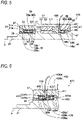
- the configuration of the spindle device of the machine tool according to the present invention in a sixth embodiment is the same configuration except that a bearing device 510 is provided instead of the bearing device 10 in Fig. 1 , the description thereof will be omitted.
- Fig. 6 the left direction will be described as the front direction and the right direction will be described as the rear direction.
- Fig. 6 a part of the bearing device 410 is illustrated, and the illustration of the displacement sensor and the control device connected to the drive motor is omitted. Further, in Fig. 6 , the same reference numerals and letters are given to the portions having the same configuration as those of Fig. 1 , and the description thereof will be omitted.
- the bearing device 510 includes the rotating member 21, the nut 39, the rear rolling bearing 41, the rear outer ring side spacer 46, the nut 47, the rear inner ring side spacer 48, the drive motor 51, a displacement sensor 500, a housing 511, a front rolling bearing 531, a front outer ring side spacer 536, and a front inner ring side spacer 538.
- the rotating member 21 (spindle shaft) having a hollow shape is rotatably supported by the front rolling bearing 531 and the rear rolling bearing 41 with respect to the housing 511 which is a fixing member.
- the rotating member 21 is rotationally driven by the drive motor 51 arranged between the front rolling bearing 531 and the rear rolling bearing 41.
- the front rolling bearing 531 is provided between the housing 511 and the rotating member 21, and is composed of a pair of angular ball bearings 531a and 531b arranged so as to form a back surface combination.
- Each of the angular ball bearings 531a and 531b includes an outer ring 533 which is a stationary raceway ring, an inner ring 534 which is a rotatory raceway ring, and a plurality of balls 535 as rolling elements arranged with a contact angle between an outer ring raceway groove which is a stationary raceway and an inner ring raceway groove which is a rotatory raceway. That is, each of the bearings 531a and 531b has the inner ring 534, the outer ring 533, and the balls 535 rotatably arranged between the inner ring 534 and the outer ring 533.
- Each of the angular ball bearings 531a and 531b has the outer ring 533 fitted in the housing 511 via the outer ring side spacer 536 and is fixed by the front bearing outer ring retainer 37 bolted to the housing 511.
- each of the angular ball bearings 531a and 531b is externally fitted to the rotating member 21 via the inner ring side spacer 538, and is fixed to the rotating member 21 by the nut 39 fastened to the rotating member 21. Therefore, the position of the rotating member 21 in the rotation-axis P direction is positioned by the front rolling bearing 531.
- Each of the outer ring 533 and the inner ring 534 of the angular ball bearing 531a is longer in the rotation-axis P direction than each of the outer ring 533 and the inner ring 534 of the angular ball bearing 531b.
- the outer ring 533 of the angular ball bearing 531a holds the displacement sensor 500.
- a radial outer surface (outer peripheral surface) 534a of the inner ring 534 faces the displacement sensor 500.
- the radial outer surface 534a of the inner ring 534 of the angular ball bearing 531a is referred to as a facing surface.
- the facing surface 534a is a measurement surface for measuring a distance between the displacement sensor 500 and the inner ring 534 of the angular ball bearing 531a by the displacement sensor 100.
- the facing surface 534a is arranged further on the rear side than the angular ball bearing 531a, which is the frontmost bearing.
- the position of the facing surface 534a changes due to the radial displacement (center deviation) of the rotation axis P or the change in the diameter of the rotating member 21.
- the front outer ring side spacer 536 is fitted to the rotating member 21.
- the front outer ring side spacer 536 includes an intermediate spacer 536a arranged between the pair of the angular ball bearing 531a and the angular ball bearing 531b, and a rear end spacer 536b located further on the rear side than the front rolling bearing 531.
- the front inner ring side spacer 538 is fitted to the rotating member 21.
- the front inner ring side spacer 538 includes a front end spacer 538a located further on the front side than the front rolling bearing 531, an intermediate spacer 538b arranged between the pair of the angular ball bearing 531a and the angular ball bearing 531b, and a rear end spacer 538c located further on the rear side than the front rolling bearing 531.
- the displacement sensors 500 are provided at three or more positions on the circumference of a circle defined on a plane orthogonal to the rotation axis P of the rotating member 21. That is, in the present embodiment, three displacement sensors 500 are provided.
- the displacement sensor 500 includes a first connector 500a held in the outer ring 533 of the angular ball bearing 531a, and a second connector 500b which is freely inserted and removed from the first connector 500a and is connected to the control device 20 through the housing 511.
- the first connector 500a of the displacement sensor 500 is provided facing the facing surface 534a in a direction orthogonal to the rotation axis P of the rotating member 21.
- the displacement sensor 500 measures a distance from the facing surface 534a and outputs an electric signal corresponding to the measured distance to the axial load measuring unit 101 of the control device 20.
- the displacement sensor 500 is installed on the non-rotating body side of the bearing device 510, and the measurement surface of the displacement sensor 500 faces the rotating body side of the bearing device 510.
- the displacement sensor 500 is a non-contact displacement sensor such as an eddy current displacement sensor, a capacitance displacement sensor, a laser displacement meter, or an air gap sensor.
- control device Since the control device according to the present embodiment has the same configuration as that of Fig. 1 , the description thereof will be omitted. Further, since the operation of the bearing device 510 is the same as the operation of the bearing device 10 according to the first embodiment, the description thereof will be omitted.
- the gap amount between the displacement sensor 500 and the facing surface 534a can be adjusted in advance.
- the displacement sensor 500 by integrating the displacement sensor 500 and the outer ring 533, it is possible to avoid the influence of a deviation between the housing 511 and the outer ring 533 when measuring the axial displacement vector of the rotation axis P of the rotating member 21 and the change in the diameter of the rotating member 21.
- the displacement sensor 500 when the displacement sensor 500 and the control device 20 are connected by wire, the displacement sensor 500 is configured to be a connector type, and thus the second connector 500b can be connected to the first connector 500a after the first connector 500a is assembled so as to be held in the outer ring 533. Therefore, the displacement sensor 500 can be installed without disconnecting a signal line connecting the displacement sensor 500 and the control device 20.
- the facing surface 534a of the inner ring 534 as the measurement surface, it is possible to accurately measure the change in the diameter of the inner ring 534 of the front rolling bearing 531.
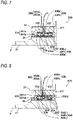
- the configuration of the spindle device of the machine tool according to the present invention in a seventh embodiment is the same configuration except that a bearing device 610 is provided instead of the bearing device 10 in Fig. 1 , the description thereof will be omitted.
- Fig. 8 the left direction will be described as the front direction and the right direction will be described as the rear direction.
- Fig. 8 a part of the bearing device 610 is illustrated, and the illustration of the displacement sensor and the control device connected to the drive motor is omitted. Further, in Fig. 8 , the same reference numerals and letters are given to the portions having the same configuration as those of Fig. 1 , and the description thereof will be omitted.
- the bearing device 610 includes the rotating member 21, the nut 39, the rear rolling bearing 41, the rear outer ring side spacer 46, the nut 47, the rear inner ring side spacer 48, the drive motor 51, a displacement sensor 600, a housing 611, a front rolling bearing 631, a front outer ring side spacer 636, and a front inner ring side spacer 638.
- the rotating member 21 (spindle shaft) having a hollow shape is rotatably supported by the front rolling bearing 631 and the rear rolling bearing 41 with respect to the housing 611 which is a fixing member.
- the rotating member 21 is rotationally driven by the drive motor 51 arranged between the front rolling bearing 631 and the rear rolling bearing 41.
- the front rolling bearing 631 is provided between the housing 611 and the rotating member 21, and is composed of a pair of angular ball bearings 631a and 631b arranged so as to form a back surface combination.
- Each of the angular ball bearings 631a and 631b includes an outer ring 633 which is a stationary raceway ring, an inner ring 634 which is a rotatory raceway ring, and a plurality of balls 635 as rolling elements arranged with a contact angle between an outer ring raceway groove which is a stationary raceway and an inner ring raceway groove which is a rotatory raceway. That is, each of the bearings 631a and 631b has the inner ring 634, the outer ring 633, and the balls 635 rotatably arranged between the inner ring 634 and the outer ring 633.
- Each of the angular ball bearings 631a and 631b has the outer ring 633 fitted in the housing 611 via the outer ring side spacer 636 and is fixed by the front bearing outer ring retainer 37 bolted to the housing 611.
- each of the angular ball bearings 631a and 631b is externally fitted to the rotating member 21 via the inner ring side spacer 638, and is fixed to the rotating member 21 by the nut 39 fastened to the rotating member 21. Therefore, the position of the rotating member 21 in the rotation-axis P direction is positioned by the front rolling bearing 631.
- the outer ring 633 of the angular ball bearing 631a extends further on the rear side than the inner ring 634 of the angular ball bearing 631a and holds the displacement sensor 600.
- the front outer ring side spacer 636 includes an intermediate spacer 636a arranged between the pair of the angular ball bearing 631a and the angular ball bearing 631b, and a rear end spacer 636b located further on the rear side than the front rolling bearing 631.
- the front inner ring side spacer 638 is fitted to the rotating member 21.
- the front inner ring side spacer 638 includes a front end spacer 638a located further on the front side than the front rolling bearing 631, an intermediate spacer 638b arranged between the pair of the angular ball bearing 631a and the angular ball bearing 631b, and a rear end spacer 638c located further on the rear side than the front rolling bearing 631.
- a radial outer surface (outer peripheral surface) 638d of the intermediate spacer 638b faces the displacement sensor 600.
- the radial outer surface 638d of the intermediate spacer 638b is referred to as a facing surface.
- the facing surface 638d is a measurement surface for measuring a distance between the displacement sensor 600 and the intermediate spacer 638b by the displacement sensor 600.
- the facing surface 638d is arranged further on the rear side than the angular ball bearing 631a, which is the frontmost bearing.
- the position of the facing surface 638d changes due to the radial displacement (center deviation) of the rotation axis P or the change in the diameter of the rotating member 21.
- the displacement sensors 600 are provided at three or more positions on the circumference of a circle defined on a plane orthogonal to the rotation axis P of the rotating member 21. That is, in the present embodiment, three displacement sensors 600 are provided.
- the displacement sensor 600 includes a first connector 600a held in the outer ring 633 of the angular ball bearing 631a, and a second connector 600b which is freely inserted and removed from the first connector 600a and is connected to the control device 20 through the housing 611.
- the first connector 600a of the displacement sensor 600 is provided facing the facing surface 638d in a direction orthogonal to the rotation axis P of the rotating member 21.
- the displacement sensor 600 measures a distance from the facing surface 638d and outputs an electric signal corresponding to the measured distance to the axial load measuring unit 101 of the control device 20.
- the displacement sensor 600 is installed on the non-rotating body side of the bearing device 610, and the measurement surface of the displacement sensor 600 faces the rotating body side of the bearing device 610.
- the displacement sensor 600 is a non-contact displacement sensor such as an eddy current displacement sensor, a capacitance displacement sensor, a laser displacement meter, or an air gap sensor.
- control device Since the control device according to the present embodiment has the same configuration as that of Fig. 1 , the description thereof will be omitted. Further, since the operation of the bearing device 610 is the same as the operation of the bearing device 10 according to the first embodiment, the description thereof will be omitted.
- the gap amount between the displacement sensor 600 and the facing surface 638d can be adjusted in advance by holding the displacement sensor 600 in the outer ring 633 of the angular ball bearing 631a.
- the displacement sensor 600 by integrating the displacement sensor 600 and the outer ring 633, it is possible to avoid the influence of a deviation between the housing 611 and the outer ring 633 when measuring the axial displacement vector of the rotation axis P of the rotating member 21 and the change in the diameter of the rotating member 21.
- the configuration of the spindle device of the machine tool according to the present invention in an eighth embodiment is the same configuration except that a bearing device 710 is provided instead of the bearing device 10 in Fig. 1 , the description thereof will be omitted.
- Fig. 9 the left direction will be described as the front direction and the right direction will be described as the rear direction.
- Fig. 9 a part of the bearing device 710 is illustrated, and the illustration of the displacement sensor and the control device connected to the drive motor is omitted. Further, in Fig. 9 , the same reference numerals and letters are given to the portions having the same configuration as those of Fig. 1 , and the description thereof will be omitted.
- the bearing device 710 includes the rotating member 21, the front rolling bearing 31, the front outer ring side spacer 36, the nut 39, the rear rolling bearing 41, the rear outer ring side spacer 46, the nut 47, the rear inner ring side spacer 48, the drive motor 51, the displacement sensor 100, a housing 711, and a front inner ring side spacer 738.
- the rotating member 21 spindle shaft having a hollow shape is rotatably supported by the front rolling bearing 31 and the rear rolling bearing 41 with respect to the housing 711 which is a fixing member.
- the rotating member 21 is rotationally driven by the drive motor 51 arranged between the front rolling bearing 31 and the rear rolling bearing 41.
- a radial outer surface (outer peripheral surface) 21a of the rotating member 21 faces the displacement sensor 100.
- the radial outer surface 21a of the rotating member 21 is referred to as a facing surface.
- the facing surface 21a is a measurement surface for measuring a distance between the displacement sensor 100 and the rotating member 21 by the displacement sensor 100.
- the facing surface 21a is arranged further on the rear side than the angular ball bearing 31a, which is the frontmost bearing. The position of the facing surface 21a changes due to the radial displacement (center deviation) of the rotation axis P or the change in the diameter of the rotating member 21.
- the front inner ring side spacer 738 is fitted to the rotating member 21.
- the front inner ring side spacer 738 includes a front end spacer 738a located further on the front side than the front rolling bearing 31, and an intermediate spacer 738b arranged between the pair of the angular ball bearing 31a and the angular ball bearing 31b.
- the displacement sensor 100 is held in the housing 711 and is provided at three or more positions on the circumference of a circle defined on a plane orthogonal to the rotation axis P of the rotating member 21.
- the displacement sensor 100 is provided so as to face the facing surface 21a in a direction orthogonal to the rotation axis P of the rotating member 21.
- the displacement sensor 100 measures a distance from the facing surface 21a and outputs an electric signal corresponding to the measured distance to the axial load measuring unit 101 of the control device 20.
- the displacement sensor 100 is installed on the non-rotating body side of the bearing device 710, and the measurement surface of the displacement sensor 100 faces the rotating body side of the bearing device 710.
- control device Since the control device according to the present embodiment has the same configuration as that of Fig. 1 , the description thereof will be omitted. Further, since the operation of the bearing device 610 is the same as the operation of the bearing device 10 according to the first embodiment, the description thereof will be omitted.
- the number of components can be reduced and the configuration can be simplified, and it is possible to eliminate the influence of the error of the gap amount between the displacement sensor 100 and the measurement surface 21a due to a deviation between the spacer and the rotation axis P of the rotating member, which occurs when the spacer and the rotating member 21 are fitted in the gap.
- a spindle device 200 of the machine tool has a pressure loss measuring unit 221, a compressed gas supply unit 230, a bearing device 240, an arithmetic processing unit PU, and a display unit DP.
- the spindle device 200 of the machine tool includes, as a set, a displacement detecting unit 201 which detects the radial displacement of the rotating member 21 using compressed gas, and the pressure loss measuring unit 221 which supplies compressed gas to the displacement detecting unit 201 and measures the pressure loss according to a gap between the front outer ring side spacer 36 and the front inner ring side spacer 38.
- a plurality of sets (here, two sets) of the displacement detecting unit 201 and the pressure loss measuring unit 221 are provided in a circumferential direction.
- a displacement measuring unit 200 includes the arithmetic processing unit PU which calculates a load amount acting on the rotating member 21 based on the measurement result of each pressure loss measuring unit 221.
- the displacement detecting units 201 are provided in three or more directions on the circumference of the circle R defined on a plane orthogonal to the rotation axis P of the rotating member 21.
- the displacement detecting unit 201 can be arranged at any position of the rotating member 21 in the rotation-axis P direction. More preferably, it is desirable to arrange the displacement detecting unit 201 near the rear of the frontmost row bearing.
- Each of the displacement detecting units 201 is configured to include the front outer ring side spacer 36 and the front inner ring side spacer 38 of the front rolling bearing 31. That is, the front outer ring side spacer 36 includes an outer peripheral side ring portion 36a in contact with axial end surfaces of the outer rings 33 of the angular ball bearings 31a and 31b facing each other, and an inner peripheral side ring portion 36b narrower than the outer peripheral side ring portion 36a.
- the outer peripheral side ring portion 36a is formed with a recess portion 36c recessed from the outside to the inside in a central portion in an axial direction.
- An inner peripheral surface of the inner peripheral side ring portion 36b faces an outer peripheral surface of the front inner ring side spacer 38 so as to form a predetermined measurement target gap g.
- a funnel-shaped compressed gas discharge nozzle 202 extending radially from a bottom of the recess portion 36c of the outer peripheral side ring portion 36a to the inner peripheral surface is formed, and the compressed gas is discharged from the compressed gas discharge nozzle 202 to the measurement target gap g between the front outer ring side spacer 36 and the front inner ring side spacer 38.
- the spindle shaft of the machine tool is a hollow shaft because a drawbar is provided in an inner diameter portion of the shaft as a mechanism for gripping the tool, and it is assumed to rotate at high speed in order to improve processing efficiency. Therefore, particularly when using high-speed rotation, rotating members such as the rotating member 21 and the front inner ring side spacer 38 expand by several to several tens of ⁇ m due to centrifugal force. Further, during spindle rotation, a temperature difference occurs between the housing 241 and the rotating member 21, and in many cases, the rotating member 21 is higher. As a result, the amount of gap between the housing 241 and the rotating member 21 is reduced by several to several tens of ⁇ m.
- the gap formed between the housing 241 and the rotating member 21, such as the gap between the front outer ring side spacer 36 and the front inner ring side spacer 38, is set several tenths of a millimeter at most in order to prevent foreign matter from entering the inside of the spindle or the rolling bearing 31.
- the measurement target gap g between the front outer ring side spacer 36 and the front inner ring side spacer 38 is set to 0.05 mm to 0.5 mm when the rotating member 21 is stationary.
- the front inner ring side spacer 38 provided in the displacement detecting unit 201 be coaxial with the rotating member 21 as much as possible. Therefore, it is desirable that the front inner ring side spacer 38 is fitted to the shaft with an intermediate fit or a tight fit.
- the housing 241 is formed with a circular opening portion 203 coaxially with the compressed gas discharge nozzle 202, reaching the recess portion 36c of the front outer ring side spacer 36 from the outer peripheral surface and reducing the inner diameter in two steps.
- one end of a compressed gas supply passage 204 formed on a rear side wall is opened in the opening portion 203.
- the other end of the compressed gas supply passage 204 communicates with a compressed gas supply passage 205 formed by opening to a rear end formed in the housing 241 and extending forward in the axial direction.
- a gas connection portion 206 as a gas direction change portion which changes the direction of the compressed gas supplied from the compressed gas supply passage 204 from the axial direction to the radial direction and supplies the compressed gas to the compressed gas discharge nozzle 202 is mounted in the opening portion 203.
- the gas connection portion 206 has a shape which can be fitted into the opening portion 203, for example, an outer peripheral shape having the same shape as the inner peripheral shape of the opening portion 203.
- the gas connection portion 206 is internally formed with a gas passage 66a communicating with the opening portion 203 and a gas passage 66b having one end communicating with the gas passage 66a and the other end communicating with the compressed gas discharge nozzle 202.
- An O-ring 67 is arranged between a side wall of the gas connection portion 206 and an inner wall of the opening portion 203, and an O-ring 68 is similarly arranged between a bottom surface of the gas connection portion 206 and a bottom surface of the recess portion 36c. These O-rings 67 and 68 prevent the leakage of compressed air.
- the gas connection portion 206 is positioned in the radial direction by making the stepped portion of the outer peripheral surface in contact with a stepped portion of the inner peripheral surface of the opening portion 203. Further, the gas connection portion 206 is prevented from coming out of the opening portion 203 by making the outer end surface in the radial direction in contact with a holding piece 209 which is screwed to the outer peripheral surface of the housing 241.
- the gas connection portion 206 is not limited to the case where the holding piece 209 prevents the gas connection portion 206 from coming off, and a flange portion can be formed on the outer peripheral surface side of the gas connection portion 206 and the flange portion can be screwed. Any fixing method can be used as a method for fixing the gas connection portion 206 to the housing 241.
- compressed gas is supplied from the compressed gas supply unit 230 to a lubrication system (not shown) by oil-air lubrication or oil mist lubrication which supplies lubricating oil to the front rolling bearing 31 and the rear rolling bearing 41.
- the compressed gas supply unit 230 includes a compressor 231 which discharges compressed gas, a regulator 232 for the lubrication system which adjusts the pressure of the compressed gas discharged from the compressor 231, and a regulator 233 for pressure loss measurement which is connected in parallel with the regulator 232.
- the first embodiment is not limited to oil-air lubrication and oil mist lubrication, for example, can be applied to grease lubrication and the like. Lubricant oil and greases are examples of lubricants.
- the lubrication system is a lubricant supply unit which supplies the lubricant to the bearings 31 and 41.
- the pressure loss measuring unit 221 includes a throttle 222 inserted in a supply path of the compressed gas, and a differential pressure sensor 223 for detecting the differential pressure on the upstream side and the downstream side of the throttle.
- the throttle 222 is inserted in a pipe 224 connecting the regulator 233 and an opening of the compressed gas supply passage 205 formed in the housing 241.
- a throttle amount of the throttle 222 is set so that the differential pressure detection value detected by the differential pressure sensor 223 when the radial displacement of the rotating member 21 is "0" while the rotating member 21 is rotating becomes a preset value.
- the pressure on the downstream side of the throttle 222 represents a pressure loss only according to the radial displacement of the rotating member 21 in consideration of the flow path resistance due to the pipe length and the pipe diameter from the throttle 222 to the displacement detecting unit 201.
- the low-pressure side of the differential pressure sensor 223 is connected to the pipe 224 on the downstream side of the throttle 222, and the high-pressure side is connected to the regulator 233 via the pipe 225.
- the differential pressure sensor 223 the differential pressure between the compressed air pressure supplied from the regulator 233 and the downstream side pressure of the throttle 222 connected to the displacement detecting unit 201, that is, the pressure loss according to the displacement of the rotating member 21 in the displacement detecting unit 201 is detected, and then the detected differential pressure detection value is output as an analog value or a digital value.
- the arithmetic processing unit PU is composed of an arithmetic processing device such as a microcomputer.
- the differential pressure detection value output from the differential pressure sensor 223 of each pressure loss measuring unit 221 is input, and the converted amount of radial displacement of the rotating member 21 is calculated based on the differential pressure detection value.
- the arithmetic processing unit PU calculates the load amount given to the rotating member 21 by multiplying the calculated converted amount of the radial displacement of the rotating member 21 by the axial rigidity value at the axial position of the compressed gas discharge nozzle 202 calculated in advance, and then the arithmetic processing unit PU outputs the arithmetic result to the display DP and displays the arithmetic result on the display DP.
- the axial rigidity value is calculated based on the load point, the bearing position of the front rolling bearing 31, the bearing rigidity, the axial rigidity, the axial position of the compressed gas discharge nozzle 202 of the displacement detecting unit 201, and the like.
- the load amount given to the rotating member 21 is not limited to the case of being calculated by the above-described calculation.
- a load calculation map showing the relationship between the load and the differential pressure detection value is created, and the load calculation map is stored in a storage portion of the arithmetic processing unit PU.
- the load amount can be calculated directly from the differential pressure detection value by referring to the load calculation map based on the differential pressure detection value detected by the differential pressure sensor 223 at the time of cutting. By doing so, it is not necessary to convert the differential pressure detection value of the differential pressure sensor 223 into the displacement amount, and thus the load amount can be easily calculated.
- the load amount can be calculated by obtaining the equation of the characteristic line of the load calculation map and substituting the differential pressure detection value of the differential pressure sensor 223 into the obtained equation.
- each pressure loss measuring unit 221 is connected in parallel to the regulator 233 as illustrated in Fig. 1 .
- Fig. 10 The configuration of the bearing device according to the present invention in the ninth embodiment will be described with reference to Fig. 10 .
- Fig. 10 the same reference numerals and letters are given to the portions having the same configuration as those of Fig. 1 , and the description thereof will be omitted.
- the bearing device 240 includes the rotating member 21, the front rolling bearing 31, the front outer ring side spacer 36, the front inner ring side spacer 38, the nut 39, the rear rolling bearing 41, the rear outer ring side spacer 46, the nut 47, the rear inner ring side spacer 48, the drive motor 51, and the housing 241.
- the housing 241 is composed of a front cylindrical portion 242 and a rear cylindrical portion 243 divided into two parts between the front rolling bearing 31 and the drive motor 51.
- the front cylindrical portion 242 is composed of a small outer diameter portion 242a on the front side having a small outer diameter and a large outer diameter portion 242b on the rear side having a larger outer diameter as compared with that of the small outer diameter portion 242a.
- Inner peripheral surfaces of the small outer diameter portion 242a and the large outer diameter portion 242b are formed to have the same inner diameter, but a bearing accommodating step portion 242c for accommodating the front rolling bearing 31 is formed from the front end side to the rear end side of the small outer diameter portion 242a.
- the rear cylindrical portion 243 is formed by a large inner diameter portion 243a having a large inner diameter and a small inner diameter portion 243b having an inner diameter smaller than that of the large inner diameter portion 243a.
- each of the angular ball bearings 31a and 31b the outer ring 33 is fitted into the bearing accommodating step portion 242c formed in the front cylindrical portion 242 of the housing 241 via the front outer ring side spacer 36. Also, each of the angular ball bearings 31a and 31b is fixed by the front bearing outer ring retainer 37 bolted to the front cylindrical portion 242 of the housing 241.
- the outer ring 42 of the rear rolling bearing 41 is fitted in the small inner diameter portion 243b of the rear cylindrical portion 243 of the housing 241. Further, the outer ring 42 of the rear rolling bearing 41 is fixed to the small inner diameter portion 243b via the rear outer ring side spacer 46 by the rear bearing retainer 45 bolted to the small inner diameter portion 243b.
- the drive motor 51 is composed of the stator 52 fitted in the large inner diameter portion 243a of the rear cylindrical portion 242 of the housing 241 and the rotor 53 externally fitted to the rotating member 21 and facing the inner peripheral side of the stator 52 via a gap.
- the compressed gas is supplied from the compressed gas supply unit 230 to the pressure loss measuring unit 221, and as described above, in a state where the rotating member 21 of the bearing device 240 is rotated and the radial displacement of the rotating member 21 is "0", the throttle amount of the throttle 222 of the pressure loss measuring unit 221 is adjusted so that the differential pressure detection value detected by the differential pressure sensor 223 becomes a preset value.
- the compressor 231 is started to adjust the pressure of the compressed gas with the regulator 232, and then the compressed gas having a set pressure is supplied to a lubricating oil supply system (not illustrated) for the front rolling bearing 31 and the rear rolling bearing 41, and the supply of the lubricant to the front rolling bearing 31 and the rear rolling bearing 41 is started.
- the pressure of the compressed gas discharged from the compressor 231 is adjusted by the regulator 233 and the compressed gas is supplied to the pressure loss measuring unit 221.
- the compressed gas supplied to the pressure loss measuring unit 221 is input to the compressed gas supply passage 205 of the housing 241 via the throttle 222.
- the compressed gas input to the compressed gas supply passage 205 is turned 90 degrees from the axial direction to the radial direction at the gas connection portion 206 from the compressed gas supply passage 204 and is supplied to the compressed gas discharge nozzle 202.
- the compressed gas supplied to the compressed gas discharge nozzle 202 is supplied to the measurement target gap g between the front outer ring side spacer 36 and the front inner ring side spacer 38. Then, when the distance of the measurement target gap g, that is, the radial displacement of the rotating member 21 increases from the state of "0", the distance of the measurement target gap g becomes smaller, and the pressure loss becomes smaller accordingly. On the contrary, when the radial displacement becomes smaller, the distance of the measurement target gap g becomes larger, and the pressure loss becomes larger accordingly.
- the measurement target gap g has a smaller gap due to the fact that, when the rotating member 21 of the hollow shaft rotates at high speed, the rotating members such as the rotating member 21 and the front inner ring side spacer 38 expand due to centrifugal force, and the temperature of the rotating member 21 becomes higher than that of the housing 241.
- the differential pressure detection value detected by the differential pressure sensor 223 becomes a preset value, and the differential pressure detection value indicating that the radial displacement of the rotating member 21 is "0" is output to the arithmetic processing unit PU.
- the differential pressure detection value input from the differential pressure sensor 223 is converted into the radial displacement of the rotating member 21, and then the load amount applied to the rotating member 21 is calculated by multiplying the converted radial displacement by a preset axial rigidity value.
- the calculated load amount is output to the display DP and displayed. In this case, since the radial displacement is "0", the load amount displayed on the display DP is "0".
- a cutting load is applied to the rotating member 21, and a radial displacement according to the cutting load is generated in the rotating member 21.
- the radial displacement depends on the direction of the cutting load applied to the rotating member 21.
- a pressure loss according to the radial displacement occurs in the compressed gas discharged from the compressed gas discharge nozzles 202 of the plurality of displacement detecting units 201 according to the radial displacement of the rotating member 21.
- the pressure loss is detected as a differential pressure detection value by the differential pressure sensor 223 of the pressure loss measuring unit 221.
- the differential pressure detection value is converted into the radial displacement of the rotating member 21 as described above in the arithmetic processing unit PU, and then the load amount applied to the rotating member 21 is calculated by multiplying the converted radial displacement by a preset axial rigidity value.
- the calculated load amount is output to the display DP and displayed.
- the displacement detecting unit 201 composed of the front outer ring side spacer 36 and the front inner ring side spacer 38 of the front rolling bearing 31
- compressed gas is discharged from the compressed gas discharge nozzle 202 to the measurement target gap g between the front outer ring side spacer 36 and the front inner ring side spacer 38. Therefore, a pressure loss of the compressed gas occurs according to the distance of the measurement target gap g, that is, the radial displacement of the rotating member 21.
- the load amount applied to the rotating member 21 can be calculated.
- the displacement detecting unit 201 with a simple configuration in which only the front outer ring side spacer 36 and the front inner ring side spacer 38 which face each other through the predetermined measurement target gap g, the compressed gas supply passage 204, the gas connection portion 206, and the compressed gas discharge nozzle 202 are provided, it is possible to generate a pressure loss according to the radial displacement of the rotating member 21. Therefore, since the displacement detecting unit 201 does not require an electrically operating component, it is not necessary to consider wiring routing or electrical insulation.
- the compressed gas is supplied to the displacement detecting unit 201 via the throttle 222, and then by detecting the differential pressure between the pressure on the downstream side of the throttle 222, that is, the displacement detecting unit 201 side, and the original pressure of the compressed gas supplied to the pressure loss measuring unit 221, the pressure loss in the displacement detecting unit 201 can be measured.
- the detected differential pressure detection value can be converted into the radial displacement of the rotating member 21 and then the load amount applied to the rotating member 21 can be calculated, or the load amount directly applied to the rotating member 21 can be calculated from the differential pressure.
- the compressed gas supply passages 204 and 65 extending in the axial direction are formed in the housing 241
- the gas passage 66b of the gas connection portion 206 may be extended to the outer peripheral side to open, and the pressure loss measuring unit 221 may be connected to this opening portion.
- the compressed gas supply passage 205 may be omitted, the compressed gas supply passage 204 may be opened on the outer peripheral surface of the housing 241, and the pressure loss measuring unit 221 may be connected to this opening portion.
- the throttle amount of the throttle 222 of the pressure loss measuring unit 221 is adjusted so that the differential pressure detection value detected by the differential pressure sensor 223 becomes a preset value.
- the present invention is not limited to this adjustment.
- the differential pressure of each pressure loss measuring unit 221 is adjusted to a certain value by the throttle 222 of the pressure loss measuring unit 221, and this state is set as displacement 0.
- the CPU 103 of the control device 20 performs predetermined control based on the calculation result of the axial load.
- the axial load may be calculated by a single electronic component having the function of the control device 20, and predetermined control may be performed based on the calculation result.
- any two or more of the configurations in the above-described first embodiment to the fourth embodiment may be combined, or any two or more of the configurations in the above-described fifth embodiment to the eighth embodiment may be combined. Any one or two or more of the configurations in the above-described fifth embodiment to the eighth embodiment may be combined with respect to the configuration in which any two or more of the configurations in the above-described first embodiment to the fourth embodiment are combined.
Landscapes
- Engineering & Computer Science (AREA)
- General Engineering & Computer Science (AREA)
- Physics & Mathematics (AREA)
- General Physics & Mathematics (AREA)
- Mechanical Engineering (AREA)
- Rolling Contact Bearings (AREA)
- Length Measuring Devices With Unspecified Measuring Means (AREA)
- Machine Tool Sensing Apparatuses (AREA)
- Turning (AREA)
Abstract
Description
- The present invention relates to a calculation method, a bearing device, and a spindle device of a machine tool.
- In recent years, there has been an increasing movement to control a cutting load on a main shaft (spindle) of a machine tool, leading to higher processing speed, higher accuracy, and longer bearing life, and as one of measures, there is an increasing need for measuring an axial load amount during operation. In addition, the need for technology to detect abnormalities in bearings in use in advance is also increasing, and along with the extension of bearing life, there is an increasing movement to operate a processing line itself without stopping as much as possible.
- In addition, it is very difficult to directly measure the axial load amount during processing, as an alternative method, a method of measuring an axial displacement using a non-contact displacement sensor such as an eddy current displacement sensor and converting the axial displacement into a cutting load is adopted. In order to convert the axial displacement to the cutting load, a rigidity value of a spindle of a machine tool is required, and the rigidity of the bearing used has a great influence on the rigidity value.
- A bearing has a characteristic that the rigidity of the bearing changes significantly due to effects of centrifugal deformation due to rotation, thermal deformation due to friction and heat generation from a motor, and specifically, a difference in thermal expansion due to a temperature difference between an inner ring and an outer ring of the bearing. Therefore, in order to convert the axial displacement to the cutting load, it is necessary to consider not only the axial displacement but also change in the rigidity of the spindle of the machine tool due to the change in the rigidity of the bearing.
- An amount of change in a difference in thermal expansion of the bearing can also be used to detect abnormalities in the bearing. Rolling friction increases as the bearing deteriorates, and heat generated by the bearing increases. At the same time, the difference in thermal expansion also changes, so a state of the bearing can be inferred by monitoring the change. Therefore, it is possible to prolong the life of the bearing by preventing serious problems such as failure of the main shaft and adjusting operating conditions so as to maintain the state of the bearing based on the monitoring result.
- In addition, in a related art, as a method of measuring axial displacement with a vector, a method of measuring at two orthogonal points is common, but this method is based on the premise that a diameter of a measurement target is constant. Therefore, it is not possible to deal with a case where the diameter changes at the same time as the axial displacement changes.
- In this situation,
Patent Literature 1 relates to a method of calculating center deviation of a rotating body, andPatent Literature 1 discloses that a calculation circle is calculated from measurement data of three points along an outer surface in a circumferential direction while rotating the rotating body, and the center deviation of the rotating body is calculated based on the calculated calculation circle. According to the method ofPatent Literature 1, by setting three measurement points, one circle can be determined on a measurement plane, so that it is possible to calculate an axial displacement vector and an amount of change in a diameter. - Patent Literature 1:
JP-B-4243639 - An object of the present invention is to provide a calculation method, a bearing device, and a spindle device of a machine tool capable of measuring an amount of radial displacement of a rotation axis and an amount of change in a diameter of a rotating member by using measurement data of three or more positions on a plane orthogonal to the rotation axis of the rotating member.
- In order to achieve the object described above, a calculation method according to an aspect of the present invention used for a bearing device including a rotating member, a bearing which supports the rotating member so that the rotating member can rotate, a housing which holds the bearing, and sensors which are installed in the housing or a non-rotating part of the bearing to measure a distance to a surface that rotates with the rotating member, includes calculating an amount of change in a diameter of the rotating member based on measurement results by the sensors provided at three or more positions on a plane orthogonal to a rotation axis of the rotating member.
- A calculation method according to another aspect of the present invention includes the steps of supplying compressed gas to a measurement target gap between a rotating member and a housing from at least three directions around a bearing in a bearing device which supports the rotating member to the housing via the bearing so that the rotating member can rotate, detecting pressure change of the compressed gas, and calculating an amount of change in a diameter of the rotating member based on the detected pressure change.
- A bearing device according to still another aspect of the present invention includes a rotating member, a bearing which supports the rotating member so that the rotating member can rotate, a housing which holds the bearing, and sensors which are installed in the housing or a non-rotating part of the bearing to measure a distance to a surface that rotates with the rotating member, where the sensors are provided at three or more positions on a circumference of a circle defined on a plane orthogonal to a rotation axis of the rotating member.
- A spindle device of a machine tool according to still another aspect of the present invention is a bearing device of a machine tool including a rotating member, a bearing which supports the rotating member so that the rotating member can rotate, a housing which holds the bearing, and sensors which are installed in the housing or a non-rotating part of the bearing to measure a distance to a surface that rotates with the rotating member, where the sensors are provided at three or more positions on a plane orthogonal to a rotation axis of the rotating member, and the bearing device further includes a calculation unit which calculates an amount of change in a diameter of the rotating member based on measurement results by the sensors.
- A spindle device of a machine tool according to still another aspect of the present invention is a bearing device of a machine tool which supports a rotating member to a housing via a bearing so that the rotating member can rotate, and includes a compressed gas supply unit which supplies compressed gas to a measurement target gap between the rotating member and the housing from at least three directions around the bearing, a detection unit which detects pressure change of the compressed gas, and a calculation unit which calculates an amount of change in a diameter of the rotating member based on the detected pressure change.
- According to the aspect of the calculation method according to the present invention, by using the measurement data of the three or more positions on the plane orthogonal to the rotation axis of the rotating member, the amount of the radial displacement of the rotation axis and the amount of change in the diameter of the rotating member can be measured.
- Further, in the bearing device according to the present invention, by using the measurement data of the three or more positions on the plane orthogonal to the rotation axis of the rotating member, the amount of the radial displacement of the rotation axis and the amount of change in the diameter of the rotating member can be measured.
- Further, in the spindle device of the machine tool according to the present invention, by using the measurement data of the three or more positions on the plane orthogonal to the rotation axis of the rotating member, the amount of the radial displacement of the rotation axis and the amount of change in the diameter of the rotating member can be measured.
-
-
Fig. 1 is a view illustrating a configuration of a spindle device of a machine tool according to the present invention in a first embodiment. -
Figs. 2A and 2B are schematic views illustrating a configuration of a bearing device according to the present invention in the first embodiment. -
Fig. 3 is a cross-sectional view illustrating a bearing device according to the present invention in a second embodiment. -
Fig. 4 is a cross-sectional view illustrating a bearing device according to the present invention in a third embodiment. -
Fig. 5 is a cross-sectional view illustrating a bearing device according to the present invention in a fourth embodiment. -
Fig. 6 is a cross-sectional view illustrating a bearing device according to the present invention in a fifth embodiment. -
Fig. 7 is a cross-sectional view illustrating a bearing device according to the present invention in a sixth embodiment. -
Fig. 8 is a cross-sectional view illustrating a bearing device according to the present invention in a seventh embodiment. -
Fig. 9 is a cross-sectional view illustrating a bearing device according to the present invention in an eighth embodiment. -
Fig. 10 is a view illustrating a configuration of a spindle device of a machine tool according to the present invention in a ninth embodiment. - Hereinafter, embodiments of the present invention will be described with reference to the accompanying drawings. In the figure, the same or similar parts are designated by the same or similar reference numerals and letters. However, the drawings are schematic, and the relationship between the thickness and the plane dimensions, the ratio of the thickness of each layer, and the like are different from the actual ones. Therefore, the specific thickness and dimensions should be determined in consideration of the following explanation. In addition, it goes without saying that parts having different dimensional relationships and ratios are included between the drawings.
- Further, the embodiments shown below exemplify devices and methods for embodying the technical idea of the present invention, and the technical idea of the present invention does not specify the material, shape, structure, arrangement, and the like of the component parts to the following. The technical idea of the present invention may be modified in various ways within the technical scope specified by the claims described in the claims.
- First, a configuration of a spindle device of a machine tool according to the present invention in a first embodiment will be described with reference to
Fig. 1 . - A
spindle device 1 of a machine tool includes abearing device 10 and acontrol device 20. - The
bearing device 10 is a motor built-in type, and can measure an axial load by detecting an amount of radial displacement of a rotation axis of a rotating member supported by a rolling bearing and an amount of change in a diameter of the rotating member. The details of the configuration of thebearing device 10 will be described below. - The
control device 20 calculates an axial load amount based on a measurement result measured by thebearing device 10. Thecontrol device 20 includes an axialload measuring unit 101, amotor drive circuit 102, and aCPU 103. - Next, the configuration of the
bearing device 10 will be described with reference toFigs. 1 to 2B . InFig. 1 , a left direction will be described as a front direction and a right direction will be described as a rear direction. InFigs. 2A and 2B, Fig. 2A illustrates a case wheredisplacement sensors 100 are provided at three positions excluding positions facing each other, andFig. 2B illustrates a case where thedisplacement sensors 100 are provided at three positions, which are positions facing each other and a position other than the positions facing each other. - Generally, a spacer is provided in the vicinity of the bearing of the bearing
device 10 for the purpose of adjusting a preload or installing a lubrication mechanism. Further, the bearings used in thegeneral bearing device 10 are roughly classified into fixed side bearings and free side bearings, each of which is composed of a single row or a double row. Here, the fixed side and the free side mean fixed and free in an axial direction. - In particular, the bearing
device 10 includes ahousing 11, a rotatingmember 21, afront rolling bearing 31, a front outerring side spacer 36, a front innerring side spacer 38, anut 39, arear rolling bearing 41, a rear outerring side spacer 46, anut 47, a rear innerring side spacer 48, adrive motor 51, and thedisplacement sensor 100. - In the
bearing device 10, the rotating member 21 (spindle of a machine tool) having a hollow shape is rotatably supported by thefront rolling bearing 31 and the rear rolling bearing 41 with respect to thehousing 11 which is a fixing member. The rotatingmember 21 is rotationally driven by thedrive motor 51 arranged between the front rollingbearing 31 and therear rolling bearing 41. - The front rolling bearing 31 as a front bearing is provided between the
housing 11 and the rotatingmember 21 in the vicinity of one end (front end) in the axial direction of a rotation axis P of the rotatingmember 21. The front rolling bearing 31 is composed of a pair of anangular ball bearing 31a as a first front bearing and anangular ball bearing 31b as a second front bearing which have substantially the same dimensions and are arranged so as to form a back surface combination. Each of theangular ball bearings outer ring 33 which is a stationary raceway ring, aninner ring 34 which is a rotatory raceway ring, and a plurality ofballs 35 as rolling elements arranged with a contact angle between an outer ring raceway groove which is a stationary raceway and an inner ring raceway groove which is a rotatory raceway. That is, each of thebearings inner ring 34, theouter ring 33, and theball 35 rotatably arranged between theinner ring 34 and theouter ring 33. - Each of the
angular ball bearings outer ring 33 fitted in thehousing 11 via the outerring side spacer 36, and is fixed by a front bearingouter ring retainer 37 bolted to thehousing 11. - Further, the
inner ring 34 of each of theangular ball bearings member 21 via an innerring side spacer 38, and is fixed to the rotatingmember 21 by thenut 39 fastened to the rotatingmember 21. Theangular ball bearings nut 39. Therefore, the position of the rotatingmember 21 in a rotation-axis P direction is positioned by thefront rolling bearing 31. - The front outer
ring side spacer 36 has anintermediate spacer 36a arranged between the pair of theangular ball bearing 31a and theangular ball bearing 31b, and arear end spacer 36b located further on a rear side than the front rollingbearing 31. - The front inner
ring side spacer 38 is fitted to the rotatingmember 21. The front innerring side spacer 38 includes afront end spacer 38a located further on a front side than the front rollingbearing 31, anintermediate spacer 38b arranged between the pair of theangular ball bearing 31a and theangular ball bearing 31b, and arear end spacer 38c located further on the rear side than the front rollingbearing 31. A radial outer surface (outer peripheral surface) 38d of theintermediate spacer 38b faces thedisplacement sensor 100. In the following description, the radialouter surface 38d of theintermediate spacer 38b is referred to as a facing surface. The facingsurface 38d is a measurement surface for measuring a distance between thedisplacement sensor 100 and theintermediate spacer 38b by thedisplacement sensor 100. The facingsurface 38d is arranged further on the rear side than theangular ball bearing 31a, which is a frontmost bearing. The position of the facingsurface 38d changes due to the radial displacement of the rotation axis P of the rotatingmember 21 or the change in the diameter of the rotatingmember 21. - The rear rolling bearing 41 as a rear bearing is a cylindrical roller bearing. The rear rolling bearing 41 is provided between the
housing 11 and the rotatingmember 21 in the vicinity of the other end (rear end) in the axial direction of the rotation axis P of the rotatingmember 21. The rear rolling bearing 41 includes anouter ring 42, aninner ring 43, and a plurality ofcylindrical rollers 44 as rolling elements. Theouter ring 42 of the rear rolling bearing 41 is fitted in thehousing 11 and is fixed in thehousing 11 via the outerring side spacer 46 by arear bearing retainer 45 bolted to thehousing 11. Theinner ring 43 of the rear rolling bearing 41 is fixed to the rotatingmember 21 via the innerring side spacer 48 by thenut 47 fastened to the rotatingmember 21. - The rear outer
ring side spacer 46 includes afront end spacer 46a located further on the front side than thebearing 41 and arear end spacer 46b located further on the rear side than therear rolling bearing 41. - The rear inner
ring side spacer 48 is fitted to the rotatingmember 21. The rear innerring side spacer 48 includes afront end spacer 48a located further on the front side than the rear rolling bearing 41 and arear end spacer 48b located further on the rear side than therear rolling bearing 41. - The
drive motor 51 is composed of astator 52 fitted in thehousing 11 and arotor 53 externally fitted to the rotatingmember 21 and facing an inner peripheral side of thestator 52 via a gap. - The
displacement sensor 100 is held in thehousing 11. Thedisplacement sensors 100 are provided at three or more positions on the circumference of a circle R (seeFig. 2A ) defined on a plane orthogonal to the rotation axis P of the rotatingmember 21, excluding the positions facing each other. That is, in the present embodiment, threedisplacement sensors 100 are provided.Fig. 2A illustrates a case where thedisplacement sensors 100 are provided at three positions S1, S2, and S3 on the circumference of the circle R. InFig. 2A , the angle between the positions S1 and S2 is set to θ1, the angle between the positions S2 and S3 is set to θ2, and the angle between the positions S3 and S1 is set to θ3. As illustrated inFig. 2A , the positions S1, S2, and S3 are arranged so that the positions S1, S2, and S3 do not face each other on the circumference of the circle R, for example, each of θ1, θ2, and θ3 is 120 degrees. When θ1 is 180 degrees, S1 and S2 are in positions facing each other. - The
displacement sensor 100 is provided so as to face the facingsurface 38d in a direction orthogonal to the rotation axis P of the rotatingmember 21. Thedisplacement sensor 100 measures a distance from the facingsurface 38d, and outputs an electric signal corresponding to the measured distance to the axialload measuring unit 101 of thecontrol device 20. Thedisplacement sensor 100 is installed on a non-rotating body side of the bearingdevice 10, and the measurement surface of thedisplacement sensor 100 faces a rotating body side of the bearingdevice 10. - The
displacement sensor 100 is a non-contact displacement sensor such as an eddy current displacement sensor, a capacitance displacement sensor, a laser displacement meter, or an air gap sensor. - Next, the configuration of the
control device 20 connected to thebearing device 10 will be described with reference toFig. 1 . The connection between the bearingdevice 10 and thecontrol device 20 may be a wired connection or a wireless connection. - As described above, the
control device 20 includes the axialload measuring unit 101, amotor drive circuit 102, and theCPU 103. - The axial
load measuring unit 101 operates under the control of theCPU 103. The axialload measuring unit 101 receives the detection values of the threedisplacement sensors 100. More specifically, the axialload measuring unit 101 receives an electric signal according to the distance to each of the three measurement surfaces input from the threedisplacement sensors 100. Then, the axialload measuring unit 101 measures the radial displacement (center deviation) of the rotation axis P of the rotatingmember 21 and the amount of change in the diameter of the rotatingmember 21 based on the electric signals. The axialload measuring unit 101 calculates the axial load based on the measured radial displacement (center deviation) of the rotation axis P and the measurement results of the amount of change in the diameter of the rotatingmember 21, and outputs the calculation result of the axial load to theCPU 103. Here, the radial displacement (center deviation) of the rotation axis P is a deviation in the direction orthogonal to the rotation axis P from a reference position of the rotation axis P of the rotatingmember 21. Further, the change in the diameter of the rotatingmember 21 is a change in the diameter with respect to the reference diameter of the rotatingmember 21. - The
motor drive circuit 102 drives thedrive motor 51 under the control of theCPU 103. - The
CPU 103 reads a control program stored in advance in a memory (not illustrated) and executes the read control program to control the entire operation of thecontrol device 20. TheCPU 103 performs predetermined control based on the calculation result of the axial load input from the axialload measuring unit 101. Here, the predetermined control is control for themotor drive circuit 102 to reduce the driving force of thedrive motor 51, or control for notifying by, for example, displaying an abnormality when the load amount of the axial load indicated by the measurement result is equal to or more than a threshold value. Thecontrol device 20 may have a display unit for displaying that the axial load is abnormal. Alternatively, thecontrol device 20 may output a signal to an external display device, and the display device may display information or an image regarding an abnormal axial load. - The
control device 20 is not limited to calculating the load amount of the axial load, but may be limited to calculating the radial displacement (center deviation) of the rotation axis P and the amount of change in the diameter of the rotatingmember 21. In this case, for example, the radial displacement (center deviation) of the rotation axis P and the amount of change in the diameter of the rotatingmember 21 may be displayed on the display device to perform notification. - Next, the operation of the
spindle device 1 of the machine tool will be described. - In a state where the rotating
member 21 of the bearingdevice 10 is rotated, thecontrol device 20 calculates a measurement circle from the measured values on the facingsurfaces 38d at three positions by using an approximation method such as the circumscribed circle center method, the inscribed circle center method, the minimum region center method, or the least squares center method with respect to the amount of displacement in the radial direction from a reference circle with any state as the reference circle. In this case, it is preferable to perform a plurality of measurements in order to improve the measurement accuracy. - Further, since the bearing
device 10 is a machine that requires high-speed rotation and high rotation accuracy, components of the bearingdevice 10 are also manufactured with high accuracy. Further, the measured displacement amount is very small, about 1 / 1,000 to 1 / 10,000, with respect to the diameter of the measurement circle. From this, since sufficient measurement accuracy can be expected even with only one measurement, the difference between the reference circle and the measurement circle may be obtained instead of the approximation method described above. Specifically, the output value of eachdisplacement sensor 100 is used as a reference value or offset by zero, and then the difference amount of the output value of eachdisplacement sensor 100 from any time point to another time point is measured. Then, the average value of the difference amounts on therespective facing surfaces 38d, which are the measurement surfaces of therespective displacement sensors 100, is set as the amount of change in the diameter between the diameter (the diameter of the circle R illustrated inFigs. 2A and 2B ) of the facingsurface 38d from the rotation axis P and the diameter of the predetermined reference circle. Further, a displacement vector displacement amount of the rotation axis P is calculated from the difference (two values) between the respective difference amounts in thedisplacement sensors 100 at two positions out of thedisplacement sensors 100 at three positions and the average value of the difference amounts. In this case, since the displacement vector displacement amount of the rotation axis P can be calculated for the number of combinations of thedisplacement sensors 100 at two positions, by using the average value of these displacement vector displacement amounts, a highly accurate displacement vector displacement amount can be obtained. The closer each angle (in the case ofFigs. 2A and 2B , θ1, θ2, and θ3) between theadjacent displacement sensors 100 on the circumference of the circle R with respect to the rotation axis P is to the same angle, the higher the measurement accuracy of the above-described displacement amount can be. - By arranging the
displacement sensors 100 as illustrated inFig. 2A , the numerical value of the diameter of the circle R or the numerical value of the diameter of the rotatingmember 21 becomes unnecessary when calculating the displacement vector displacement amount and the amount of change in the diameter, and thus the displacement vector displacement amount and the amount of change in the diameter can be calculated only by the measured values of the threedisplacement sensors 100. More specifically, the amount of change in the diameter can be calculated from the measured values of the threedisplacement sensors 100, and the displacement vector displacement amount can be calculated using any two of the measured values of the threedisplacement sensors 100. In this case, since three values of the displacement vector displacement amount can be obtained by the combination, the accuracy of the displacement vector displacement amount is improved by averaging the three values. Even when thedisplacement sensors 100 face each other (for example, in the case ofFig. 2B ), the displacement vector displacement amount can be calculated by the calculation method described above. However, since the displacement vector displacement amount cannot be calculated with the displacement sensors 100 (for example, thedisplacement sensors 100 at the positions S1 and S2 inFig. 2B ) having an opposite combination, the obtained displacement vector displacement amount becomes two values, and the accuracy is lowered. - Further, in either case of
Fig. 2A and Fig. 2B , when the diameter value of the circle R or the diameter value of the rotatingmember 21 is known, since the coordinates of the diameter of the rotatingmember 21 on the arrangement axis of eachdisplacement sensor 100 are determined together with the measured values of the threedisplacement sensors 100, the displacement vector displacement amount and the amount of change in the diameter can be calculated from the changes in these coordinates. - The change in the diameter of the rotating
member 21 and the amount of radial displacement of the rotation axis P measured by thespindle device 1 of the machine tool are caused by a centrifugal expansion amount with respect to the reference circle and the difference in thermal expansion due to the temperature difference between the installation position of thedisplacement sensor 100 and the measurement surface. Here, the centrifugal expansion amount is constant at any position, but the difference in thermal expansion amount becomes smaller as thedisplacement sensor 100 is closer to the bearing because a deviation from the bearing becomes smaller. However, the difference in thermal expansion amount can be corrected when the relationship between the temperature rise of the bearing and the temperature rise at the position of thedisplacement sensor 100 is clarified in advance. - Thus, according to the present embodiment, by arranging the
displacement sensor 100 in theintermediate portion 38b of the front innerring side spacer 38 installed further on the rear side than the frontmostangular ball bearing 31a, the change amount and the displacement amount at the same level as the bearing closest to the axial load can be measured. Therefore, it is possible to suppress an increase in the distance (distance between the tool end (working point) and an intersection (support point) between the contact angle of the bearing with respect to the rotatingmember 21 and the rotation axis P) between a tool end and the bearing, which greatly affects the rigidity of the bearingdevice 10, and it is possible to accurately measure the temperature change of the bearing due to rotation. - In the embodiment described above, the
front rolling bearing 31 has two rolling bearings (angular ball bearings), but thefront rolling bearing 31 may be composed of one or three or more rolling bearings. - Since the configuration of the spindle device of the machine tool according to the present invention in a second embodiment is the same configuration except that a
bearing device 110 is provided instead of the bearingdevice 10 inFig. 1 , the description thereof will be omitted. - Next, the configuration of the
bearing device 110 according to the present invention in the second embodiment will be described with reference toFig. 3 . InFig. 3 , the left direction will be described as the front direction and the right direction will be described as the rear direction. InFig. 3 , the illustration of the lower half of thebearing device 110 is omitted, and the illustration of the displacement sensor and the control device connected to the drive motor is omitted. Further, inFig. 3 , the same reference numerals and letters are given to the portions having the same configuration as those ofFig. 1 , and the description thereof will be omitted. - The
bearing device 110 includes the rotatingmember 21, thefront rolling bearing 31, the front outerring side spacer 36, the front innerring side spacer 38, thenut 39, therear rolling bearing 41, the rear outerring side spacer 46, thenut 47, the rear innerring side spacer 48, thedrive motor 51, thedisplacement sensor 100, and ahousing 111. - In the
bearing device 110, the rotating member 21 (spindle shaft) having a hollow shape is rotatably supported by thefront rolling bearing 31 and the rear rolling bearing 41 with respect to thehousing 111 which is a fixing member. - The front inner
ring side spacer 38 is fitted to the rotatingmember 21. The front innerring side spacer 38 includes thefront end spacer 38a located further on the front side than the front rollingbearing 31, theintermediate spacer 38b arranged between the pair of theangular ball bearing 31a and theangular ball bearing 31b, and therear end spacer 38c located further on the rear side than the front rollingbearing 31. A radial outer surface (outer peripheral surface) 38e of therear end spacer 38c faces thedisplacement sensor 100. In the following description, the radialouter surface 38e of therear end spacer 38c is referred to as a facing surface. The facingsurface 38e is a measurement surface for measuring the distance between thedisplacement sensor 100 and therear end spacer 38c by thedisplacement sensor 100. The facingsurface 38e is arranged further on the rear side than theangular ball bearing 31a, which is the frontmost bearing. The position of the facingsurface 38e changes due to the radial displacement (center deviation) of the rotation axis P or the change in the diameter of the rotatingmember 21. - The
displacement sensor 100 is held in thehousing 111. Also, thedisplacement sensor 100 is located further on the rear end side in the axial direction P than theangular ball bearing 31b. Thedisplacement sensors 100 are provided at three or more positions on the circumference of a circle defined on the plane orthogonal to the rotation axis P of the rotatingmember 21, which is located at therear end spacer 38c of the front innerring side spacer 38 closest to thedrive motor 51. Thedisplacement sensor 100 is provided so as to face the facingsurface 38e in a direction orthogonal to the rotation axis P of the rotatingmember 21. Thedisplacement sensor 100 measures a distance from the facingsurface 38e and outputs an electric signal corresponding to the measured distance to the axialload measuring unit 101 of thecontrol device 20. Thedisplacement sensor 100 is installed on the non-rotating body side of thebearing device 110, and the measurement surface of thedisplacement sensor 100 faces the rotating body side of thebearing device 110. - Since the control device according to the present embodiment has the same configuration as that of
Fig. 1 , the description thereof will be omitted. Further, since the operation of thebearing device 110 is the same as the operation of the bearingdevice 10 according to the first embodiment, the description thereof will be omitted. - In the case of a
general bearing device 110, from the degree of heat generation of the front rolling bearing 31 itself or the rear rolling bearing 41 itself, or the degree of heat generation or heat dissipation from thedrive motor 51, in thefront rolling bearing 31 and therear rolling bearing 41, theouter ring 33 and theouter ring 42 on the non-rotating body side of the bearingdevice 10 in the vicinity of thedrive motor 51 are thermally the most severe. In the present embodiment, the facingsurface 38e of therear end spacer 38c of the thermally severe front innerring side spacer 38 is used as the measurement surface of thedisplacement sensor 100. Therefore, since it is possible to detect the influence of heat of thedrive motor 51 at an early stage in addition to the machining load as well as the machining load, it is possible to take early measures against deterioration due to the influence of heat of the front rolling bearing 31 or therear rolling bearing 41. As a result, it is possible to suppress the shortening of the life of thebearing device 110. - Since the configuration of the spindle device of the machine tool according to the present invention in a third embodiment is the same configuration except that a
bearing device 210 is provided instead of the bearingdevice 10 inFig. 1 , the description thereof will be omitted. - Next, the configuration of the
bearing device 210 according to the present invention in the third embodiment will be described with reference toFig. 4 . InFig. 4 , the left direction will be described as the front direction and the right direction will be described as the rear direction. InFig. 4 , the illustration of the lower half of thebearing device 210 is omitted, and the illustration of the displacement sensor and the control device connected to the drive motor is omitted. Further, inFig. 4 , the same reference numerals and letters are given to the portions having the same configuration as those ofFig. 1 , and the description thereof will be omitted. - The
bearing device 210 includes the rotatingmember 21, thefront rolling bearing 31, the front outerring side spacer 36, the front innerring side spacer 38, thenut 39, therear rolling bearing 41, the rear outerring side spacer 46, thenut 47, the rear innerring side spacer 48, thedrive motor 51, thedisplacement sensor 100, and ahousing 211. - In the
bearing device 210, the rotating member 21 (spindle shaft) having a hollow shape is rotatably supported by thefront rolling bearing 31 and the rear rolling bearing 41 with respect to thehousing 211 which is a fixing member. - The rear inner
ring side spacer 48 is fitted to the rotatingmember 21. A radial outer surface (outer peripheral surface) 48c of therear end spacer 48b of the rear innerring side spacer 48 faces thedisplacement sensor 100. In the following description, the radialouter surface 48c of therear end spacer 48b is referred to as a facing surface. The facingsurface 48c is a measurement surface for measuring the distance between thedisplacement sensor 100 and therear end spacer 48b by thedisplacement sensor 100. The facingsurface 48c is arranged further on the rear side than theangular ball bearing 31a, which is the frontmost bearing. The position of the facingsurface 48c changes due to the radial displacement (center deviation) of the rotation axis P or the change in the diameter of the rotatingmember 21. - The
displacement sensors 100 are installed in the vicinity of the rear rolling bearing 41 which is a free side bearing. Thedisplacement sensors 100 are held in thehousing 211 and are provided at three or more positions on the circumference of a circle defined on a plane orthogonal to the rotation axis P of the rotatingmember 21. Thedisplacement sensor 100 is provided so as to face the facingsurface 48c in a direction orthogonal to the rotation axis P of the rotatingmember 21. Thedisplacement sensor 100 measures a distance from the facingsurface 48c and outputs an electric signal corresponding to the measured distance to the axialload measuring unit 101 of thecontrol device 20. Thedisplacement sensor 100 is installed on the non-rotating body side of thebearing device 210, and the measurement surface of thedisplacement sensor 100 faces the rotating body side of thebearing device 210. - Since the control device according to the present embodiment has the same configuration as that of
Fig. 1 , the description thereof will be omitted. Further, since the operation of thebearing device 210 is the same as the operation of the bearingdevice 10 according to the first embodiment, the description thereof will be omitted. - Thus, according to the present embodiment, by arranging the
displacement sensors 100 in the vicinity of therear rolling bearing 41, it is possible to measure the axial displacement vector of the rotation axis P of the rotatingmember 21 and the change in the diameter of the rotatingmember 21. - Since the configuration of the spindle device of the machine tool according to the present invention in a fourth embodiment is the same configuration except that a
bearing device 310 is provided instead of the bearingdevice 10 inFig. 1 , the description thereof will be omitted. - Next, the configuration of the
bearing device 310 according to the present invention in the fourth embodiment will be described with reference toFig. 5 . InFig. 5 , the left direction will be described as the front direction and the right direction will be described as the rear direction. InFig. 5 , the illustration of the lower half of thebearing device 310 is omitted, and the illustration of the displacement sensor and the control device connected to the drive motor is omitted. Further, inFig. 5 , the same reference numerals and letters are given to the portions having the same configuration as those ofFig. 1 , and the description thereof will be omitted. - The
bearing device 310 includes the rotatingmember 21, thefront rolling bearing 31, the front outerring side spacer 36, the front innerring side spacer 38, thenut 39, therear rolling bearing 41, the rear outerring side spacer 46, thenut 47, the rear innerring side spacer 48, thedrive motor 51, thedisplacement sensor 100, and ahousing 311. - In the
bearing device 310, the rotating member 21 (spindle shaft) having a hollow shape is rotatably supported by thefront rolling bearing 31 and the rear rolling bearing 41 with respect to thehousing 311 which is a fixing member. The rotatingmember 21 is rotationally driven by thedrive motor 51 arranged between the front rollingbearing 31 and therear rolling bearing 41. - The rear inner
ring side spacer 48 is fitted to the rotatingmember 21. A radial outer surface (outer peripheral surface) 48d of thefront end spacer 48a of the rear innerring side spacer 48 faces thedisplacement sensor 100. In the following description, the radialouter surface 48d of thefront end spacer 48a is referred to as a facing surface. The facingsurface 48d is a measurement surface for measuring the distance between thedisplacement sensor 100 and thefront end spacer 48a by thedisplacement sensor 100. The facingsurface 48d is arranged further on the rear side than theangular ball bearing 31a, which is the frontmost bearing. The position of the facingsurface 48d changes due to the radial displacement (center deviation) of the rotation axis P or the change in the diameter of the rotatingmember 21. - The
displacement sensors 100 are installed in the vicinity of the rear rolling bearing 41 which is a free side bearing. Thedisplacement sensors 100 are held in thehousing 311 and are provided at three or more positions on the circumference of a circle defined on a plane orthogonal to the rotation axis P of the rotatingmember 21. Thedisplacement sensor 100 is provided so as to face the facingsurface 48d in a direction orthogonal to the rotation axis P of the rotatingmember 21. Thedisplacement sensor 100 measures a distance from the facingsurface 48d and outputs an electric signal corresponding to the measured distance to the axialload measuring unit 101 of thecontrol device 20. Thedisplacement sensor 100 is installed on the non-rotating body side of thebearing device 310, and the measurement surface of thedisplacement sensor 100 faces the rotating body side of thebearing device 310. - Since the control device according to the present embodiment has the same configuration as that of
Fig. 1 , the description thereof will be omitted. Further, since the operation of thebearing device 310 is the same as the operation of the bearingdevice 10 according to the first embodiment, the description thereof will be omitted. - In the present embodiment, the amount of heat flowing from the
drive motor 51 to the rear rolling bearing 41 can be easily estimated by setting the position closer to thedrive motor 51 than the rear rolling bearing 41 as the measurement surface of thedisplacement sensor 100. - Since the configuration of the spindle device of the machine tool according to the present invention in a fifth embodiment is the same configuration except that a
bearing device 410 is provided instead of the bearingdevice 10 inFig. 1 , the description thereof will be omitted. - Next, the configuration of the
bearing device 410 according to the present invention in the fifth embodiment will be described with reference toFig. 6 . InFig. 6 , the left direction will be described as the front direction and the right direction will be described as the rear direction. InFig. 6 , a part of thebearing device 410 is illustrated, and the illustration of the displacement sensor and the control device connected to the drive motor is omitted. Further, inFig. 6 , the same reference numerals and letters are given to the portions having the same configuration as those ofFig. 1 , and the description thereof will be omitted. - The
bearing device 410 includes the rotatingmember 21, thenut 39, therear rolling bearing 41, the rear outerring side spacer 46, thenut 47, the rear innerring side spacer 48, thedrive motor 51, thedisplacement sensor 100, ahousing 411, a front rolling bearing 431, a front outerring side spacer 436, and a front innerring side spacer 438. - In the
bearing device 410, the rotating member 21 (spindle shaft) having a hollow shape is rotatably supported by the front rolling bearing 431 and the rear rolling bearing 41 with respect to thehousing 411 which is a fixing member. The rotatingmember 21 is rotationally driven by thedrive motor 51 arranged between the front rolling bearing 431 and therear rolling bearing 41. - The front rolling bearing 431 is provided between the
housing 411 and the rotatingmember 21, and is composed of a pair ofangular ball bearings angular ball bearings outer ring 433 which is a stationary raceway ring, aninner ring 434 which is a rotatory raceway ring, and a plurality ofballs 435 as rolling elements arranged with a contact angle between an outer ring raceway groove which is a stationary raceway and an inner ring raceway groove which is a rotatory raceway. That is, each of thebearings inner ring 434, theouter ring 433, and theballs 435 rotatably arranged between theinner ring 434 and theouter ring 433. - Each of the
angular ball bearings outer ring 433 fitted in thehousing 411 via the outerring side spacer 436 and is fixed by the front bearingouter ring retainer 37 bolted to thehousing 411. - Further, the
inner ring 434 of each of theangular ball bearings member 21 via the innerring side spacer 438, and is fixed to the rotatingmember 21 by thenut 39 fastened to the rotatingmember 21. Therefore, the position of the rotatingmember 21 in the rotation-axis P direction is positioned by thefront rolling bearing 431. - The
inner ring 434 of theangular ball bearing 431a extends further on the rear side than theouter ring 433 of theangular ball bearing 431a. A radial outer surface (outer peripheral surface) 434a of theinner ring 434 of theangular ball bearing 431a faces thedisplacement sensor 100. In the following description, the radialouter surface 434a of theinner ring 434 of theangular ball bearing 431a is referred to as a facing surface. The facingsurface 434a is a measurement surface for measuring a distance between thedisplacement sensor 100 and theinner ring 434 of theangular ball bearing 431a by thedisplacement sensor 100. The facingsurface 434a is arranged further on the rear side than theangular ball bearing 431a, which is the frontmost bearing. The position of the facingsurface 434a changes due to the radial displacement (center deviation) of the rotation axis P or the change in the diameter of the rotatingmember 21. - The front outer
ring side spacer 436 includes anintermediate spacer 436a arranged between the pair of theangular ball bearing 431a and theangular ball bearing 431b, and arear end spacer 436b located further on the rear side than thefront rolling bearing 431. - The front inner
ring side spacer 438 is fitted to the rotatingmember 21. The front innerring side spacer 438 includes a front end spacer 438a located further on the front side than the front rolling bearing 431, anintermediate spacer 438b arranged between the pair of theangular ball bearing 431a and theangular ball bearing 431b, and arear end spacer 438c located further on the rear side than thefront rolling bearing 431. - The
displacement sensor 100 is provided so as to face the facingsurface 434a in a direction orthogonal to the rotation axis P of the rotatingmember 21. Thedisplacement sensor 100 measures a distance from the facingsurface 434a and outputs an electric signal corresponding to the measured distance to the axialload measuring unit 101 of thecontrol device 20. Thedisplacement sensor 100 is installed on the non-rotating body side of thebearing device 410, and the measurement surface of thedisplacement sensor 100 faces the rotating body side of thebearing device 410. - Since the control device according to the present embodiment has the same configuration as that of
Fig. 1 , the description thereof will be omitted. Further, since the operation of thebearing device 410 is the same as the operation of the bearingdevice 10 according to the first embodiment, the description thereof will be omitted. - In the present embodiment, by using the facing
surface 434a of theinner ring 434 of the front rolling bearing 431 as the measurement surface of thedisplacement sensor 100, the change in the diameter of theinner ring 434 of the front rolling bearing 431 can be measured more accurately. - Since the configuration of the spindle device of the machine tool according to the present invention in a sixth embodiment is the same configuration except that a
bearing device 510 is provided instead of the bearingdevice 10 inFig. 1 , the description thereof will be omitted. - Next, the configuration of the
bearing device 510 according to the present invention in the sixth embodiment will be described with reference toFig. 7 . InFig. 6 , the left direction will be described as the front direction and the right direction will be described as the rear direction. InFig. 6 , a part of thebearing device 410 is illustrated, and the illustration of the displacement sensor and the control device connected to the drive motor is omitted. Further, inFig. 6 , the same reference numerals and letters are given to the portions having the same configuration as those ofFig. 1 , and the description thereof will be omitted. - The
bearing device 510 includes the rotatingmember 21, thenut 39, therear rolling bearing 41, the rear outerring side spacer 46, thenut 47, the rear innerring side spacer 48, thedrive motor 51, adisplacement sensor 500, ahousing 511, a front rolling bearing 531, a front outerring side spacer 536, and a front innerring side spacer 538. - In the
bearing device 510, the rotating member 21 (spindle shaft) having a hollow shape is rotatably supported by the front rolling bearing 531 and the rear rolling bearing 41 with respect to thehousing 511 which is a fixing member. The rotatingmember 21 is rotationally driven by thedrive motor 51 arranged between the front rolling bearing 531 and therear rolling bearing 41. - The front rolling bearing 531 is provided between the
housing 511 and the rotatingmember 21, and is composed of a pair ofangular ball bearings angular ball bearings outer ring 533 which is a stationary raceway ring, aninner ring 534 which is a rotatory raceway ring, and a plurality ofballs 535 as rolling elements arranged with a contact angle between an outer ring raceway groove which is a stationary raceway and an inner ring raceway groove which is a rotatory raceway. That is, each of thebearings inner ring 534, theouter ring 533, and theballs 535 rotatably arranged between theinner ring 534 and theouter ring 533. - Each of the
angular ball bearings outer ring 533 fitted in thehousing 511 via the outerring side spacer 536 and is fixed by the front bearingouter ring retainer 37 bolted to thehousing 511. - Further, the
inner ring 534 of each of theangular ball bearings member 21 via the innerring side spacer 538, and is fixed to the rotatingmember 21 by thenut 39 fastened to the rotatingmember 21. Therefore, the position of the rotatingmember 21 in the rotation-axis P direction is positioned by thefront rolling bearing 531. - Each of the
outer ring 533 and theinner ring 534 of theangular ball bearing 531a is longer in the rotation-axis P direction than each of theouter ring 533 and theinner ring 534 of theangular ball bearing 531b. Theouter ring 533 of theangular ball bearing 531a holds thedisplacement sensor 500. A radial outer surface (outer peripheral surface) 534a of theinner ring 534 faces thedisplacement sensor 500. In the following description, the radialouter surface 534a of theinner ring 534 of theangular ball bearing 531a is referred to as a facing surface. The facingsurface 534a is a measurement surface for measuring a distance between thedisplacement sensor 500 and theinner ring 534 of theangular ball bearing 531a by thedisplacement sensor 100. The facingsurface 534a is arranged further on the rear side than theangular ball bearing 531a, which is the frontmost bearing. The position of the facingsurface 534a changes due to the radial displacement (center deviation) of the rotation axis P or the change in the diameter of the rotatingmember 21. - The front outer
ring side spacer 536 is fitted to the rotatingmember 21. The front outerring side spacer 536 includes anintermediate spacer 536a arranged between the pair of theangular ball bearing 531a and theangular ball bearing 531b, and arear end spacer 536b located further on the rear side than thefront rolling bearing 531. - The front inner
ring side spacer 538 is fitted to the rotatingmember 21. The front innerring side spacer 538 includes afront end spacer 538a located further on the front side than the front rolling bearing 531, anintermediate spacer 538b arranged between the pair of theangular ball bearing 531a and theangular ball bearing 531b, and arear end spacer 538c located further on the rear side than thefront rolling bearing 531. - The
displacement sensors 500 are provided at three or more positions on the circumference of a circle defined on a plane orthogonal to the rotation axis P of the rotatingmember 21. That is, in the present embodiment, threedisplacement sensors 500 are provided. - The
displacement sensor 500 includes afirst connector 500a held in theouter ring 533 of theangular ball bearing 531a, and asecond connector 500b which is freely inserted and removed from thefirst connector 500a and is connected to thecontrol device 20 through thehousing 511. - The
first connector 500a of thedisplacement sensor 500 is provided facing the facingsurface 534a in a direction orthogonal to the rotation axis P of the rotatingmember 21. Thedisplacement sensor 500 measures a distance from the facingsurface 534a and outputs an electric signal corresponding to the measured distance to the axialload measuring unit 101 of thecontrol device 20. Thedisplacement sensor 500 is installed on the non-rotating body side of thebearing device 510, and the measurement surface of thedisplacement sensor 500 faces the rotating body side of thebearing device 510. - The
displacement sensor 500 is a non-contact displacement sensor such as an eddy current displacement sensor, a capacitance displacement sensor, a laser displacement meter, or an air gap sensor. - Since the control device according to the present embodiment has the same configuration as that of
Fig. 1 , the description thereof will be omitted. Further, since the operation of thebearing device 510 is the same as the operation of the bearingdevice 10 according to the first embodiment, the description thereof will be omitted. - In the present embodiment, by holding the
displacement sensor 500 in theouter ring 533 of theangular ball bearing 531a and integrating thedisplacement sensor 500 and theouter ring 533, the gap amount between thedisplacement sensor 500 and the facingsurface 534a can be adjusted in advance. - Further, in the present embodiment, by integrating the
displacement sensor 500 and theouter ring 533, it is possible to avoid the influence of a deviation between thehousing 511 and theouter ring 533 when measuring the axial displacement vector of the rotation axis P of the rotatingmember 21 and the change in the diameter of the rotatingmember 21. - Further, in the present embodiment, when the
displacement sensor 500 and thecontrol device 20 are connected by wire, thedisplacement sensor 500 is configured to be a connector type, and thus thesecond connector 500b can be connected to thefirst connector 500a after thefirst connector 500a is assembled so as to be held in theouter ring 533. Therefore, thedisplacement sensor 500 can be installed without disconnecting a signal line connecting thedisplacement sensor 500 and thecontrol device 20. - Further, in the present embodiment, by using the facing
surface 534a of theinner ring 534 as the measurement surface, it is possible to accurately measure the change in the diameter of theinner ring 534 of thefront rolling bearing 531. - Since the configuration of the spindle device of the machine tool according to the present invention in a seventh embodiment is the same configuration except that a
bearing device 610 is provided instead of the bearingdevice 10 inFig. 1 , the description thereof will be omitted. - Next, the configuration of the
bearing device 610 according to the present invention in the seventh embodiment will be described with reference toFig. 8 . InFig. 8 , the left direction will be described as the front direction and the right direction will be described as the rear direction. InFig. 8 , a part of thebearing device 610 is illustrated, and the illustration of the displacement sensor and the control device connected to the drive motor is omitted. Further, inFig. 8 , the same reference numerals and letters are given to the portions having the same configuration as those ofFig. 1 , and the description thereof will be omitted. - The
bearing device 610 includes the rotatingmember 21, thenut 39, therear rolling bearing 41, the rear outerring side spacer 46, thenut 47, the rear innerring side spacer 48, thedrive motor 51, adisplacement sensor 600, ahousing 611, a front rolling bearing 631, a front outerring side spacer 636, and a front innerring side spacer 638. - In the
bearing device 610, the rotating member 21 (spindle shaft) having a hollow shape is rotatably supported by the front rolling bearing 631 and the rear rolling bearing 41 with respect to thehousing 611 which is a fixing member. The rotatingmember 21 is rotationally driven by thedrive motor 51 arranged between the front rolling bearing 631 and therear rolling bearing 41. - The front rolling bearing 631 is provided between the
housing 611 and the rotatingmember 21, and is composed of a pair ofangular ball bearings angular ball bearings outer ring 633 which is a stationary raceway ring, aninner ring 634 which is a rotatory raceway ring, and a plurality ofballs 635 as rolling elements arranged with a contact angle between an outer ring raceway groove which is a stationary raceway and an inner ring raceway groove which is a rotatory raceway. That is, each of thebearings inner ring 634, theouter ring 633, and theballs 635 rotatably arranged between theinner ring 634 and theouter ring 633. - Each of the
angular ball bearings outer ring 633 fitted in thehousing 611 via the outerring side spacer 636 and is fixed by the front bearingouter ring retainer 37 bolted to thehousing 611. - Further, the
inner ring 634 of each of theangular ball bearings member 21 via the innerring side spacer 638, and is fixed to the rotatingmember 21 by thenut 39 fastened to the rotatingmember 21. Therefore, the position of the rotatingmember 21 in the rotation-axis P direction is positioned by thefront rolling bearing 631. - The
outer ring 633 of theangular ball bearing 631a extends further on the rear side than theinner ring 634 of theangular ball bearing 631a and holds thedisplacement sensor 600. - The front outer
ring side spacer 636 includes anintermediate spacer 636a arranged between the pair of theangular ball bearing 631a and theangular ball bearing 631b, and arear end spacer 636b located further on the rear side than thefront rolling bearing 631. - The front inner
ring side spacer 638 is fitted to the rotatingmember 21. The front innerring side spacer 638 includes afront end spacer 638a located further on the front side than the front rolling bearing 631, anintermediate spacer 638b arranged between the pair of theangular ball bearing 631a and theangular ball bearing 631b, and arear end spacer 638c located further on the rear side than thefront rolling bearing 631. A radial outer surface (outer peripheral surface) 638d of theintermediate spacer 638b faces thedisplacement sensor 600. In the following description, the radialouter surface 638d of theintermediate spacer 638b is referred to as a facing surface. The facingsurface 638d is a measurement surface for measuring a distance between thedisplacement sensor 600 and theintermediate spacer 638b by thedisplacement sensor 600. The facingsurface 638d is arranged further on the rear side than theangular ball bearing 631a, which is the frontmost bearing. The position of the facingsurface 638d changes due to the radial displacement (center deviation) of the rotation axis P or the change in the diameter of the rotatingmember 21. - The
displacement sensors 600 are provided at three or more positions on the circumference of a circle defined on a plane orthogonal to the rotation axis P of the rotatingmember 21. That is, in the present embodiment, threedisplacement sensors 600 are provided. - The
displacement sensor 600 includes afirst connector 600a held in theouter ring 633 of theangular ball bearing 631a, and asecond connector 600b which is freely inserted and removed from thefirst connector 600a and is connected to thecontrol device 20 through thehousing 611. - The
first connector 600a of thedisplacement sensor 600 is provided facing the facingsurface 638d in a direction orthogonal to the rotation axis P of the rotatingmember 21. Thedisplacement sensor 600 measures a distance from the facingsurface 638d and outputs an electric signal corresponding to the measured distance to the axialload measuring unit 101 of thecontrol device 20. Thedisplacement sensor 600 is installed on the non-rotating body side of thebearing device 610, and the measurement surface of thedisplacement sensor 600 faces the rotating body side of thebearing device 610. - The
displacement sensor 600 is a non-contact displacement sensor such as an eddy current displacement sensor, a capacitance displacement sensor, a laser displacement meter, or an air gap sensor. - Since the control device according to the present embodiment has the same configuration as that of
Fig. 1 , the description thereof will be omitted. Further, since the operation of thebearing device 610 is the same as the operation of the bearingdevice 10 according to the first embodiment, the description thereof will be omitted. - In the present embodiment, the gap amount between the
displacement sensor 600 and the facingsurface 638d can be adjusted in advance by holding thedisplacement sensor 600 in theouter ring 633 of theangular ball bearing 631a. - Further, in the present embodiment, by integrating the
displacement sensor 600 and theouter ring 633, it is possible to avoid the influence of a deviation between thehousing 611 and theouter ring 633 when measuring the axial displacement vector of the rotation axis P of the rotatingmember 21 and the change in the diameter of the rotatingmember 21. - Since the configuration of the spindle device of the machine tool according to the present invention in an eighth embodiment is the same configuration except that a
bearing device 710 is provided instead of the bearingdevice 10 inFig. 1 , the description thereof will be omitted. - Next, the configuration of the
bearing device 710 according to the present invention in the eighth embodiment will be described with reference toFig. 9 . InFig. 9 , the left direction will be described as the front direction and the right direction will be described as the rear direction. InFig. 9 , a part of thebearing device 710 is illustrated, and the illustration of the displacement sensor and the control device connected to the drive motor is omitted. Further, inFig. 9 , the same reference numerals and letters are given to the portions having the same configuration as those ofFig. 1 , and the description thereof will be omitted. - The
bearing device 710 includes the rotatingmember 21, thefront rolling bearing 31, the front outerring side spacer 36, thenut 39, therear rolling bearing 41, the rear outerring side spacer 46, thenut 47, the rear innerring side spacer 48, thedrive motor 51, thedisplacement sensor 100, ahousing 711, and a front innerring side spacer 738. - In the
bearing device 710, the rotating member 21 (spindle shaft) having a hollow shape is rotatably supported by thefront rolling bearing 31 and the rear rolling bearing 41 with respect to thehousing 711 which is a fixing member. - The rotating
member 21 is rotationally driven by thedrive motor 51 arranged between the front rollingbearing 31 and therear rolling bearing 41. A radial outer surface (outer peripheral surface) 21a of the rotatingmember 21 faces thedisplacement sensor 100. In the following description, the radialouter surface 21a of the rotatingmember 21 is referred to as a facing surface. The facingsurface 21a is a measurement surface for measuring a distance between thedisplacement sensor 100 and the rotatingmember 21 by thedisplacement sensor 100. The facingsurface 21a is arranged further on the rear side than theangular ball bearing 31a, which is the frontmost bearing. The position of the facingsurface 21a changes due to the radial displacement (center deviation) of the rotation axis P or the change in the diameter of the rotatingmember 21. - The front inner
ring side spacer 738 is fitted to the rotatingmember 21. The front innerring side spacer 738 includes afront end spacer 738a located further on the front side than the front rollingbearing 31, and anintermediate spacer 738b arranged between the pair of theangular ball bearing 31a and theangular ball bearing 31b. - The
displacement sensor 100 is held in thehousing 711 and is provided at three or more positions on the circumference of a circle defined on a plane orthogonal to the rotation axis P of the rotatingmember 21. - The
displacement sensor 100 is provided so as to face the facingsurface 21a in a direction orthogonal to the rotation axis P of the rotatingmember 21. Thedisplacement sensor 100 measures a distance from the facingsurface 21a and outputs an electric signal corresponding to the measured distance to the axialload measuring unit 101 of thecontrol device 20. Thedisplacement sensor 100 is installed on the non-rotating body side of thebearing device 710, and the measurement surface of thedisplacement sensor 100 faces the rotating body side of thebearing device 710. - Since the control device according to the present embodiment has the same configuration as that of
Fig. 1 , the description thereof will be omitted. Further, since the operation of thebearing device 610 is the same as the operation of the bearingdevice 10 according to the first embodiment, the description thereof will be omitted. - In the present embodiment, by providing the measurement surface on the rotating
member 21, the number of components can be reduced and the configuration can be simplified, and it is possible to eliminate the influence of the error of the gap amount between thedisplacement sensor 100 and themeasurement surface 21a due to a deviation between the spacer and the rotation axis P of the rotating member, which occurs when the spacer and the rotatingmember 21 are fitted in the gap. - The configuration of the spindle device of the machine tool according to the present invention in a ninth embodiment will be described with reference to
Fig. 10 . - A
spindle device 200 of the machine tool has a pressureloss measuring unit 221, a compressedgas supply unit 230, abearing device 240, an arithmetic processing unit PU, and a display unit DP. - Specifically, the
spindle device 200 of the machine tool includes, as a set, adisplacement detecting unit 201 which detects the radial displacement of the rotatingmember 21 using compressed gas, and the pressureloss measuring unit 221 which supplies compressed gas to thedisplacement detecting unit 201 and measures the pressure loss according to a gap between the front outerring side spacer 36 and the front innerring side spacer 38. A plurality of sets (here, two sets) of thedisplacement detecting unit 201 and the pressureloss measuring unit 221 are provided in a circumferential direction. Further, adisplacement measuring unit 200 includes the arithmetic processing unit PU which calculates a load amount acting on the rotatingmember 21 based on the measurement result of each pressureloss measuring unit 221. - The
displacement detecting units 201 are provided in three or more directions on the circumference of the circle R defined on a plane orthogonal to the rotation axis P of the rotatingmember 21. Thedisplacement detecting unit 201 can be arranged at any position of the rotatingmember 21 in the rotation-axis P direction. More preferably, it is desirable to arrange thedisplacement detecting unit 201 near the rear of the frontmost row bearing. - Each of the
displacement detecting units 201 is configured to include the front outerring side spacer 36 and the front innerring side spacer 38 of the front rollingbearing 31. That is, the front outerring side spacer 36 includes an outer peripheralside ring portion 36a in contact with axial end surfaces of theouter rings 33 of theangular ball bearings side ring portion 36b narrower than the outer peripheralside ring portion 36a. - The outer peripheral
side ring portion 36a is formed with a recess portion 36c recessed from the outside to the inside in a central portion in an axial direction. An inner peripheral surface of the inner peripheralside ring portion 36b faces an outer peripheral surface of the front innerring side spacer 38 so as to form a predetermined measurement target gap g. - Then, a funnel-shaped compressed
gas discharge nozzle 202 extending radially from a bottom of the recess portion 36c of the outer peripheralside ring portion 36a to the inner peripheral surface is formed, and the compressed gas is discharged from the compressedgas discharge nozzle 202 to the measurement target gap g between the front outerring side spacer 36 and the front innerring side spacer 38. - Here, in many cases, the spindle shaft of the machine tool is a hollow shaft because a drawbar is provided in an inner diameter portion of the shaft as a mechanism for gripping the tool, and it is assumed to rotate at high speed in order to improve processing efficiency. Therefore, particularly when using high-speed rotation, rotating members such as the rotating
member 21 and the front innerring side spacer 38 expand by several to several tens of µm due to centrifugal force. Further, during spindle rotation, a temperature difference occurs between thehousing 241 and the rotatingmember 21, and in many cases, the rotatingmember 21 is higher. As a result, the amount of gap between thehousing 241 and the rotatingmember 21 is reduced by several to several tens of µm. - Also, in the spindle of the machine tool, the gap formed between the
housing 241 and the rotatingmember 21, such as the gap between the front outerring side spacer 36 and the front innerring side spacer 38, is set several tenths of a millimeter at most in order to prevent foreign matter from entering the inside of the spindle or the rollingbearing 31. - Therefore, the measurement target gap g between the front outer
ring side spacer 36 and the front innerring side spacer 38 is set to 0.05 mm to 0.5 mm when the rotatingmember 21 is stationary. However, since the amount of change in pressure loss with respect to the radial displacement of the rotatingmember 21 increases as the gap amount decreases, it is preferable to set the measurement target gap g to 0.05 mm to 0.2 mm. - In order to accurately measure the measurement target gap g between the front outer
ring side spacer 36 and the front innerring side spacer 38 during operation, it is desirable that the front innerring side spacer 38 provided in thedisplacement detecting unit 201 be coaxial with the rotatingmember 21 as much as possible. Therefore, it is desirable that the front innerring side spacer 38 is fitted to the shaft with an intermediate fit or a tight fit. - The
housing 241 is formed with acircular opening portion 203 coaxially with the compressedgas discharge nozzle 202, reaching the recess portion 36c of the front outerring side spacer 36 from the outer peripheral surface and reducing the inner diameter in two steps. As illustrated inFig. 10 , one end of a compressedgas supply passage 204 formed on a rear side wall is opened in theopening portion 203. As illustrated inFig. 10 , the other end of the compressedgas supply passage 204 communicates with a compressedgas supply passage 205 formed by opening to a rear end formed in thehousing 241 and extending forward in the axial direction. - Further, as illustrated in
Figs. 2A and 2B , agas connection portion 206 as a gas direction change portion which changes the direction of the compressed gas supplied from the compressedgas supply passage 204 from the axial direction to the radial direction and supplies the compressed gas to the compressedgas discharge nozzle 202 is mounted in theopening portion 203. Thegas connection portion 206 has a shape which can be fitted into theopening portion 203, for example, an outer peripheral shape having the same shape as the inner peripheral shape of theopening portion 203. Thegas connection portion 206 is internally formed with a gas passage 66a communicating with theopening portion 203 and a gas passage 66b having one end communicating with the gas passage 66a and the other end communicating with the compressedgas discharge nozzle 202. An O-ring 67 is arranged between a side wall of thegas connection portion 206 and an inner wall of theopening portion 203, and an O-ring 68 is similarly arranged between a bottom surface of thegas connection portion 206 and a bottom surface of the recess portion 36c. These O-rings 67 and 68 prevent the leakage of compressed air. - Further, as illustrated in
Figs. 2A and 2B , thegas connection portion 206 is positioned in the radial direction by making the stepped portion of the outer peripheral surface in contact with a stepped portion of the inner peripheral surface of theopening portion 203. Further, thegas connection portion 206 is prevented from coming out of theopening portion 203 by making the outer end surface in the radial direction in contact with a holding piece 209 which is screwed to the outer peripheral surface of thehousing 241. Thegas connection portion 206 is not limited to the case where the holding piece 209 prevents thegas connection portion 206 from coming off, and a flange portion can be formed on the outer peripheral surface side of thegas connection portion 206 and the flange portion can be screwed. Any fixing method can be used as a method for fixing thegas connection portion 206 to thehousing 241. - As illustrated in
Fig. 1 , in the pressureloss measuring unit 221, compressed gas is supplied from the compressedgas supply unit 230 to a lubrication system (not shown) by oil-air lubrication or oil mist lubrication which supplies lubricating oil to thefront rolling bearing 31 and therear rolling bearing 41. The compressedgas supply unit 230 includes acompressor 231 which discharges compressed gas, aregulator 232 for the lubrication system which adjusts the pressure of the compressed gas discharged from thecompressor 231, and aregulator 233 for pressure loss measurement which is connected in parallel with theregulator 232. The first embodiment is not limited to oil-air lubrication and oil mist lubrication, for example, can be applied to grease lubrication and the like. Lubricant oil and greases are examples of lubricants. The lubrication system is a lubricant supply unit which supplies the lubricant to thebearings - The pressure
loss measuring unit 221 includes athrottle 222 inserted in a supply path of the compressed gas, and adifferential pressure sensor 223 for detecting the differential pressure on the upstream side and the downstream side of the throttle. - The
throttle 222 is inserted in apipe 224 connecting theregulator 233 and an opening of the compressedgas supply passage 205 formed in thehousing 241. A throttle amount of thethrottle 222 is set so that the differential pressure detection value detected by thedifferential pressure sensor 223 when the radial displacement of the rotatingmember 21 is "0" while the rotatingmember 21 is rotating becomes a preset value. As a result, the pressure on the downstream side of thethrottle 222 represents a pressure loss only according to the radial displacement of the rotatingmember 21 in consideration of the flow path resistance due to the pipe length and the pipe diameter from thethrottle 222 to thedisplacement detecting unit 201. - The low-pressure side of the
differential pressure sensor 223 is connected to thepipe 224 on the downstream side of thethrottle 222, and the high-pressure side is connected to theregulator 233 via thepipe 225. In thedifferential pressure sensor 223, the differential pressure between the compressed air pressure supplied from theregulator 233 and the downstream side pressure of thethrottle 222 connected to thedisplacement detecting unit 201, that is, the pressure loss according to the displacement of the rotatingmember 21 in thedisplacement detecting unit 201 is detected, and then the detected differential pressure detection value is output as an analog value or a digital value. - The arithmetic processing unit PU is composed of an arithmetic processing device such as a microcomputer. In the arithmetic processing unit PU, the differential pressure detection value output from the
differential pressure sensor 223 of each pressureloss measuring unit 221 is input, and the converted amount of radial displacement of the rotatingmember 21 is calculated based on the differential pressure detection value. Further, the arithmetic processing unit PU calculates the load amount given to the rotatingmember 21 by multiplying the calculated converted amount of the radial displacement of the rotatingmember 21 by the axial rigidity value at the axial position of the compressedgas discharge nozzle 202 calculated in advance, and then the arithmetic processing unit PU outputs the arithmetic result to the display DP and displays the arithmetic result on the display DP. Here, the axial rigidity value is calculated based on the load point, the bearing position of the front rollingbearing 31, the bearing rigidity, the axial rigidity, the axial position of the compressedgas discharge nozzle 202 of thedisplacement detecting unit 201, and the like. - The load amount given to the rotating
member 21 is not limited to the case of being calculated by the above-described calculation. For example, by repeatedly measuring the differential pressure detection value output from thedifferential pressure sensor 223 of the pressureloss measuring unit 221 when applying a known load to the rotatingmember 21, a load calculation map showing the relationship between the load and the differential pressure detection value is created, and the load calculation map is stored in a storage portion of the arithmetic processing unit PU. In this case, the load amount can be calculated directly from the differential pressure detection value by referring to the load calculation map based on the differential pressure detection value detected by thedifferential pressure sensor 223 at the time of cutting. By doing so, it is not necessary to convert the differential pressure detection value of thedifferential pressure sensor 223 into the displacement amount, and thus the load amount can be easily calculated. In this case, instead of using the load calculation map, the load amount can be calculated by obtaining the equation of the characteristic line of the load calculation map and substituting the differential pressure detection value of thedifferential pressure sensor 223 into the obtained equation. - Since two or more sets of the
displacement detecting unit 201 and the pressureloss measuring unit 221 are provided as described above, each pressureloss measuring unit 221 is connected in parallel to theregulator 233 as illustrated inFig. 1 . - The configuration of the bearing device according to the present invention in the ninth embodiment will be described with reference to
Fig. 10 . InFig. 10 , the same reference numerals and letters are given to the portions having the same configuration as those ofFig. 1 , and the description thereof will be omitted. - The
bearing device 240 includes the rotatingmember 21, thefront rolling bearing 31, the front outerring side spacer 36, the front innerring side spacer 38, thenut 39, therear rolling bearing 41, the rear outerring side spacer 46, thenut 47, the rear innerring side spacer 48, thedrive motor 51, and thehousing 241. - The
housing 241 is composed of a frontcylindrical portion 242 and a rearcylindrical portion 243 divided into two parts between the front rollingbearing 31 and thedrive motor 51. - The front
cylindrical portion 242 is composed of a smallouter diameter portion 242a on the front side having a small outer diameter and a largeouter diameter portion 242b on the rear side having a larger outer diameter as compared with that of the smallouter diameter portion 242a. Inner peripheral surfaces of the smallouter diameter portion 242a and the largeouter diameter portion 242b are formed to have the same inner diameter, but a bearing accommodatingstep portion 242c for accommodating the front rolling bearing 31 is formed from the front end side to the rear end side of the smallouter diameter portion 242a. - On the contrary, the rear
cylindrical portion 243 is formed by a largeinner diameter portion 243a having a large inner diameter and a smallinner diameter portion 243b having an inner diameter smaller than that of the largeinner diameter portion 243a. - In each of the
angular ball bearings outer ring 33 is fitted into the bearing accommodatingstep portion 242c formed in the frontcylindrical portion 242 of thehousing 241 via the front outerring side spacer 36. Also, each of theangular ball bearings outer ring retainer 37 bolted to the frontcylindrical portion 242 of thehousing 241. - The
outer ring 42 of the rear rolling bearing 41 is fitted in the smallinner diameter portion 243b of the rearcylindrical portion 243 of thehousing 241. Further, theouter ring 42 of the rear rolling bearing 41 is fixed to the smallinner diameter portion 243b via the rear outerring side spacer 46 by therear bearing retainer 45 bolted to the smallinner diameter portion 243b. - The
drive motor 51 is composed of thestator 52 fitted in the largeinner diameter portion 243a of the rearcylindrical portion 242 of thehousing 241 and therotor 53 externally fitted to the rotatingmember 21 and facing the inner peripheral side of thestator 52 via a gap. - The operation of the spindle device of the machine tool according to the present invention in the ninth embodiment will be described with reference to
Fig. 10 . - First, the compressed gas is supplied from the compressed
gas supply unit 230 to the pressureloss measuring unit 221, and as described above, in a state where the rotatingmember 21 of thebearing device 240 is rotated and the radial displacement of the rotatingmember 21 is "0", the throttle amount of thethrottle 222 of the pressureloss measuring unit 221 is adjusted so that the differential pressure detection value detected by thedifferential pressure sensor 223 becomes a preset value. - Next, in a state where the rotating
member 21 of thebearing device 240 is stopped, thecompressor 231 is started to adjust the pressure of the compressed gas with theregulator 232, and then the compressed gas having a set pressure is supplied to a lubricating oil supply system (not illustrated) for the front rollingbearing 31 and therear rolling bearing 41, and the supply of the lubricant to thefront rolling bearing 31 and therear rolling bearing 41 is started. - At the same time as, or before and after the start of the supply of the lubricant, the pressure of the compressed gas discharged from the
compressor 231 is adjusted by theregulator 233 and the compressed gas is supplied to the pressureloss measuring unit 221. - The compressed gas supplied to the pressure
loss measuring unit 221 is input to the compressedgas supply passage 205 of thehousing 241 via thethrottle 222. The compressed gas input to the compressedgas supply passage 205 is turned 90 degrees from the axial direction to the radial direction at thegas connection portion 206 from the compressedgas supply passage 204 and is supplied to the compressedgas discharge nozzle 202. - The compressed gas supplied to the compressed
gas discharge nozzle 202 is supplied to the measurement target gap g between the front outerring side spacer 36 and the front innerring side spacer 38. Then, when the distance of the measurement target gap g, that is, the radial displacement of the rotatingmember 21 increases from the state of "0", the distance of the measurement target gap g becomes smaller, and the pressure loss becomes smaller accordingly. On the contrary, when the radial displacement becomes smaller, the distance of the measurement target gap g becomes larger, and the pressure loss becomes larger accordingly. Here, as described above, the measurement target gap g has a smaller gap due to the fact that, when the rotatingmember 21 of the hollow shaft rotates at high speed, the rotating members such as the rotatingmember 21 and the front innerring side spacer 38 expand due to centrifugal force, and the temperature of the rotatingmember 21 becomes higher than that of thehousing 241. - Therefore, in the no-load state where the radial displacement of the rotating
member 21 is "0", the differential pressure detection value detected by thedifferential pressure sensor 223 becomes a preset value, and the differential pressure detection value indicating that the radial displacement of the rotatingmember 21 is "0" is output to the arithmetic processing unit PU. - Therefore, in the arithmetic processing unit PU, the differential pressure detection value input from the
differential pressure sensor 223 is converted into the radial displacement of the rotatingmember 21, and then the load amount applied to the rotatingmember 21 is calculated by multiplying the converted radial displacement by a preset axial rigidity value. The calculated load amount is output to the display DP and displayed. In this case, since the radial displacement is "0", the load amount displayed on the display DP is "0". - When cutting is started in this state, for example, a cutting load is applied to the rotating
member 21, and a radial displacement according to the cutting load is generated in the rotatingmember 21. The radial displacement depends on the direction of the cutting load applied to the rotatingmember 21. - Therefore, a pressure loss according to the radial displacement occurs in the compressed gas discharged from the compressed
gas discharge nozzles 202 of the plurality ofdisplacement detecting units 201 according to the radial displacement of the rotatingmember 21. The pressure loss is detected as a differential pressure detection value by thedifferential pressure sensor 223 of the pressureloss measuring unit 221. - By supplying the detected differential pressure detection value to the arithmetic processing unit PU, the differential pressure detection value is converted into the radial displacement of the rotating
member 21 as described above in the arithmetic processing unit PU, and then the load amount applied to the rotatingmember 21 is calculated by multiplying the converted radial displacement by a preset axial rigidity value. The calculated load amount is output to the display DP and displayed. - Thus, according to the present embodiment, by supplying compressed gas to the
displacement detecting unit 201 composed of the front outerring side spacer 36 and the front innerring side spacer 38 of the front rollingbearing 31, compressed gas is discharged from the compressedgas discharge nozzle 202 to the measurement target gap g between the front outerring side spacer 36 and the front innerring side spacer 38. Therefore, a pressure loss of the compressed gas occurs according to the distance of the measurement target gap g, that is, the radial displacement of the rotatingmember 21. By detecting the pressure loss with thedifferential pressure sensor 223 of the pressureloss measuring unit 221 provided outside thehousing 241 and supplying the detected differential pressure detection value to the arithmetic processing unit PU, the load amount applied to the rotatingmember 21 can be calculated. - Therefore, in the
displacement detecting unit 201, with a simple configuration in which only the front outerring side spacer 36 and the front innerring side spacer 38 which face each other through the predetermined measurement target gap g, the compressedgas supply passage 204, thegas connection portion 206, and the compressedgas discharge nozzle 202 are provided, it is possible to generate a pressure loss according to the radial displacement of the rotatingmember 21. Therefore, since thedisplacement detecting unit 201 does not require an electrically operating component, it is not necessary to consider wiring routing or electrical insulation. - In the pressure
loss measuring unit 221, the compressed gas is supplied to thedisplacement detecting unit 201 via thethrottle 222, and then by detecting the differential pressure between the pressure on the downstream side of thethrottle 222, that is, thedisplacement detecting unit 201 side, and the original pressure of the compressed gas supplied to the pressureloss measuring unit 221, the pressure loss in thedisplacement detecting unit 201 can be measured. The detected differential pressure detection value can be converted into the radial displacement of the rotatingmember 21 and then the load amount applied to the rotatingmember 21 can be calculated, or the load amount directly applied to the rotatingmember 21 can be calculated from the differential pressure. - Therefore, when the rotating
member 21 is rotatably supported by a rolling bearing, with a simple configuration, it is possible to calculate the radial displacement of the rotatingmember 21 using the compressed gas, and to calculate the load amount applied to the rotatingmember 21. - In the present embodiment, a case where the compressed
gas supply passages 204 and 65 extending in the axial direction are formed in thehousing 241 has been described, but the present invention is not limited to this. The gas passage 66b of thegas connection portion 206 may be extended to the outer peripheral side to open, and the pressureloss measuring unit 221 may be connected to this opening portion. Alternatively, the compressedgas supply passage 205 may be omitted, the compressedgas supply passage 204 may be opened on the outer peripheral surface of thehousing 241, and the pressureloss measuring unit 221 may be connected to this opening portion. - Further, in the present embodiment, a case where, in a state where the rotating
member 21 of thebearing device 240 is rotated and the radial displacement of the rotatingmember 21 is "0", the throttle amount of thethrottle 222 of the pressureloss measuring unit 221 is adjusted so that the differential pressure detection value detected by thedifferential pressure sensor 223 becomes a preset value is described. However, the present invention is not limited to this adjustment. For example, in a state where the rotatingmember 21 of thebearing device 240 is stopped (0 rotation) without an external load, the differential pressure of each pressureloss measuring unit 221 is adjusted to a certain value by thethrottle 222 of the pressureloss measuring unit 221, and this state is set as displacement 0. Then, when the rotation speed of the rotatingmember 21 is changed, the differential pressure of each pressureloss measuring unit 221 changes according to the rotation speed of the rotatingmember 21, so that the differential pressure set as displacement 0 is also offset by the same amount. Then, after the rotation speed becomes stable, a trigger signal is given from the outside in the same no-load state as described above, and the value at that time is set to "0" again. As a result, when the rotation of the rotatingmember 21 is constant, it is possible to measure at different rotation speeds in the same manner as in the first embodiment. - Although specific embodiments are described above, the embodiments are merely examples and are not intended to limit the scope of the present invention. The devices and methods described in this specification can be embodied in forms other than those described above. Further, without departing from the scope of the present invention, omissions, substitutions, and modifications can be made to the above-described embodiments as appropriate. Such omissions, substitutions, and modifications are included in the claims and equivalents thereof and fall within the technical scope of the present invention.
- Specifically, in the first to eighth embodiments, the
CPU 103 of thecontrol device 20 performs predetermined control based on the calculation result of the axial load. However, the present invention is not limited to this, the axial load may be calculated by a single electronic component having the function of thecontrol device 20, and predetermined control may be performed based on the calculation result. - Further, any two or more of the configurations in the above-described first embodiment to the fourth embodiment may be combined, or any two or more of the configurations in the above-described fifth embodiment to the eighth embodiment may be combined. Any one or two or more of the configurations in the above-described fifth embodiment to the eighth embodiment may be combined with respect to the configuration in which any two or more of the configurations in the above-described first embodiment to the fourth embodiment are combined.
- Although various embodiments are described above with reference to the drawings, it goes without saying that the present invention is not limited to such examples. It is clear that a person skilled in the art can come up with various modifications or amendments within the scope of the claims, and it is naturally understood that these also belong to the technical scope of the present invention. Further, components in the above-described embodiments may be freely combined as long as the gist of the invention is not deviated.
- This application is based on a Japanese patent application filed on January 10, 2020 (
Japanese Patent Application No. 2020-002835 -
- 1: spindle device of machine tool
- 10: bearing device
- 11: housing
- 20: control device
- 21: rotating member
- 31: front rolling bearing
- 31a, 31b: angular ball bearing
- 33: outer ring
- 34: inner ring
- 35: ball
- 36: front outer ring side spacer
- 38: front inner ring side spacer
- 41: rear rolling bearing
- 46: rear outer ring side spacer
- 48: rear inner ring side spacer
- 51: drive motor
- 52: stator
- 53: rotor
- 100: displacement sensor
- 101: axial load measuring unit
- 102: motor drive circuit
- 103: CPU
- R: circle
- S1, S2, S3: position
Claims (16)
- A calculation method used for a bearing device including a rotating member, a bearing which supports the rotating member so that the rotating member can rotate, a housing which holds the bearing, and sensors which are installed in the housing or a non-rotating part of the bearing to measure a distance to a surface that rotates with the rotating member, the method comprising:
calculating an amount of change in a diameter of the rotating member based on measurement results by the sensors provided at three or more positions on a plane orthogonal to a rotation axis of the rotating member. - The calculation method according to claim 1, further comprising:
calculating an amount of radial displacement of the rotation axis based on the measurement results by the sensors provided at the three or more positions. - A calculation method, comprising the steps of:supplying compressed gas to a measurement target gap between a rotating member and a housing from at least three directions around a bearing in a bearing device which supports the rotating member to the housing via the bearing so that the rotating member can rotate;detecting pressure change of the compressed gas; andcalculating an amount of change in a diameter of the rotating member based on the detected pressure change.
- The calculation method according to claim 3, further comprising the step of:
calculating an amount of radial displacement of the rotating member based on the detected pressure change. - A bearing device, comprising:a rotating member;a bearing which supports the rotating member so that the rotating member can rotate;a housing which holds the bearing; andsensors which are installed in the housing or a non-rotating part of the bearing to measure a distance to a surface that rotates with the rotating member, whereinthe sensors are provided at three or more positions on a circumference of a circle defined on a plane orthogonal to a rotation axis of the rotating member.
- The bearing device according to claim 5, whereinthe bearing includes a front bearing provided near one end of the rotating member in an axial direction and a rear bearing provided near the other end of the rotating member in the axial direction, andthe plane orthogonal to the rotation axis of the rotating member is not located further on one end side of the rotating member in the axial direction than the front bearing.
- The bearing device according to claim 6, whereinthe front bearing includes a first front bearing and a second front bearing located further on the other end side of the rotating member in the axial direction than the first front bearing, andthe plane orthogonal to the rotation axis of the rotating member is located between the first front bearing and the second front bearing.
- The bearing device according to claim 6, whereinthe front bearing includes a first front bearing and a second front bearing located further on the other end side of the rotating member in the axial direction than the first front bearing, andthe plane orthogonal to the rotation axis of the rotating member is located further on the other end side of the rotating member in the axial direction than the second front bearing.
- The bearing device according to any one of claims 5 to 8, wherein
the surface that rotates with the rotating member is an outer surface of an inner ring of the bearing. - The bearing device according to any one of claims 5 to 8, wherein
the surface that rotates with the rotating member is provided in a spacer provided along with an inner ring of the bearing. - The bearing device according to any one of claims 5 to 8, wherein
the surface that rotates with the rotating member is an outer peripheral surface of the rotating member. - The bearing device according to claim 5, claim 6, or claim 8, whereinthe bearing includes a front bearing provided near one end of the rotating member in an axial direction and a rear bearing provided near the other end of the rotating member in the axial direction,the bearing device of a machine tool includes a motor for rotating the rotating member, the motor being arranged between the front bearing and the rear bearing, andthe plane orthogonal to the rotation axis of the rotating member is provided on an inner ring side spacer of the front bearing closest to the motor.
- The bearing device according to any one of claims 5 to 12, whereinthe non-rotating part of the bearing is an outer ring of the bearing, andthe sensor is provided in the outer ring of the bearing.
- The bearing device according to any one of claims 5 to 13, wherein
the rotating member is a spindle of a machine tool. - A spindle device of a machine tool comprising:a rotating member;a bearing which supports the rotating member so that the rotating member can rotate;a housing which holds the bearing; andsensors which are installed in the housing or a non-rotating part of the bearing to measure a distance to a surface that rotates with the rotating member, whereinthe sensors are provided at three or more positions on a plane orthogonal to a rotation axis of the rotating member, andthe spindle device further includes a calculation unit which calculates an amount of change in a diameter of the rotating member based on measurement results by the sensors.
- A spindle device of a machine tool which supports a rotating member to a housing via a bearing so that the rotating member can rotate, the device comprising:a compressed gas supply unit which supplies compressed gas to a measurement target gap between the rotating member and the housing from at least three directions around the bearing;a detection unit which detects pressure change of the compressed gas; anda calculation unit which calculates an amount of change in a diameter of the rotating member based on the detected pressure change.
Applications Claiming Priority (2)
| Application Number | Priority Date | Filing Date | Title |
|---|---|---|---|
| JP2020002835A JP7543649B2 (en) | 2020-01-10 | 2020-01-10 | Calculation method, bearing device and spindle device of machine tool |
| PCT/JP2020/047578 WO2021140887A1 (en) | 2020-01-10 | 2020-12-18 | Calculation method, bearing device, and spindle device for machine tool |
Publications (3)
| Publication Number | Publication Date |
|---|---|
| EP4088839A1 true EP4088839A1 (en) | 2022-11-16 |
| EP4088839A4 EP4088839A4 (en) | 2023-05-31 |
| EP4088839B1 EP4088839B1 (en) | 2024-05-29 |
Family
ID=76787480
Family Applications (1)
| Application Number | Title | Priority Date | Filing Date |
|---|---|---|---|
| EP20911395.0A Active EP4088839B1 (en) | 2020-01-10 | 2020-12-18 | Calculation method, bearing device, and spindle device for machine tool |
Country Status (4)
| Country | Link |
|---|---|
| EP (1) | EP4088839B1 (en) |
| JP (1) | JP7543649B2 (en) |
| CN (1) | CN115038538A (en) |
| WO (1) | WO2021140887A1 (en) |
Families Citing this family (3)
| Publication number | Priority date | Publication date | Assignee | Title |
|---|---|---|---|---|
| JP7766442B2 (en) * | 2021-09-27 | 2025-11-10 | Ntn株式会社 | Bearing device and spindle device |
| JP7830297B2 (en) * | 2022-11-14 | 2026-03-16 | ジャパンマリンユナイテッド株式会社 | Wear inspection equipment and ships |
| CN117346675A (en) * | 2023-09-05 | 2024-01-05 | 三峡金沙江川云水电开发有限公司 | A device for measuring the upper guide shoe clearance of a hydrogenerator |
Family Cites Families (15)
| Publication number | Priority date | Publication date | Assignee | Title |
|---|---|---|---|---|
| JPS56168108A (en) * | 1980-05-29 | 1981-12-24 | Mitsubishi Electric Corp | Detecting device for abrasion loss of plain bearing metal |
| US4971517A (en) * | 1988-12-27 | 1990-11-20 | Allied-Signal Inc. | Turbine blade clearance controller |
| JP3696398B2 (en) * | 1997-04-28 | 2005-09-14 | Ntn株式会社 | Hydrostatic magnetic compound bearing and spindle device |
| JP3789650B2 (en) * | 1998-07-13 | 2006-06-28 | Ntn株式会社 | Processing machine and spindle device thereof |
| JP2000110836A (en) * | 1998-10-06 | 2000-04-18 | Ntn Corp | Hydrostatic bearing device |
| DE19919007B4 (en) * | 1999-04-27 | 2005-03-24 | Fag Kugelfischer Ag | Device for measuring bearing data |
| JP3390968B2 (en) * | 2000-06-09 | 2003-03-31 | 株式会社東京精密 | Outer diameter measuring method and device |
| JP4946177B2 (en) * | 2005-05-24 | 2012-06-06 | 日本精工株式会社 | Rolling bearing unit with displacement measuring device and rolling bearing unit with load measuring device |
| JP2008082425A (en) * | 2006-09-27 | 2008-04-10 | Ntn Corp | Magnetic bearing device |
| JP4243639B2 (en) | 2007-04-11 | 2009-03-25 | 三菱重工業株式会社 | Rotating body misalignment calculating method and misalignment calculating system |
| JP5598078B2 (en) * | 2010-05-11 | 2014-10-01 | 株式会社ジェイテクト | Machine tool spindle equipment |
| JP5510052B2 (en) * | 2010-05-14 | 2014-06-04 | 株式会社ジェイテクト | Machine tool spindle equipment |
| JP7009222B2 (en) * | 2018-01-11 | 2022-01-25 | 三菱パワー株式会社 | Rotating machine and wear condition judgment method |
| JP2020002835A (en) | 2018-06-27 | 2020-01-09 | 株式会社日立製作所 | Wind power generator, control method thereof, and wind power generation system |
| WO2020012715A1 (en) * | 2018-07-11 | 2020-01-16 | 日本精工株式会社 | Bearing device and machine tool spindle apparatus |
-
2020
- 2020-01-10 JP JP2020002835A patent/JP7543649B2/en active Active
- 2020-12-18 CN CN202080092565.0A patent/CN115038538A/en active Pending
- 2020-12-18 WO PCT/JP2020/047578 patent/WO2021140887A1/en not_active Ceased
- 2020-12-18 EP EP20911395.0A patent/EP4088839B1/en active Active
Also Published As
| Publication number | Publication date |
|---|---|
| WO2021140887A1 (en) | 2021-07-15 |
| EP4088839A4 (en) | 2023-05-31 |
| CN115038538A (en) | 2022-09-09 |
| EP4088839B1 (en) | 2024-05-29 |
| JP2021110639A (en) | 2021-08-02 |
| JP7543649B2 (en) | 2024-09-03 |
Similar Documents
| Publication | Publication Date | Title |
|---|---|---|
| EP4088839B1 (en) | Calculation method, bearing device, and spindle device for machine tool | |
| EP3754218B1 (en) | Bearing device and spindle device | |
| EP3786602B1 (en) | Bearing device and machine tool spindle apparatus | |
| CN116323051B (en) | Bearing assembly | |
| JP2020133889A (en) | Bearing device and spindle device | |
| JP5842965B2 (en) | Spindle device of machine tool provided with bearing device with load sensor | |
| EP3848597B1 (en) | Bearing device | |
| JP2000110836A (en) | Hydrostatic bearing device | |
| JP6662500B1 (en) | Bearing device and spindle device of machine tool | |
| JP7831228B2 (en) | Bearing device | |
| WO2019159838A1 (en) | Bearing device and spindle device | |
| TWI924696B (en) | Bearing assembly | |
| JP2021014885A (en) | Bearing device and spindle device |
Legal Events
| Date | Code | Title | Description |
|---|---|---|---|
| STAA | Information on the status of an ep patent application or granted ep patent |
Free format text: STATUS: THE INTERNATIONAL PUBLICATION HAS BEEN MADE |
|
| PUAI | Public reference made under article 153(3) epc to a published international application that has entered the european phase |
Free format text: ORIGINAL CODE: 0009012 |
|
| STAA | Information on the status of an ep patent application or granted ep patent |
Free format text: STATUS: REQUEST FOR EXAMINATION WAS MADE |
|
| 17P | Request for examination filed |
Effective date: 20220707 |
|
| AK | Designated contracting states |
Kind code of ref document: A1 Designated state(s): AL AT BE BG CH CY CZ DE DK EE ES FI FR GB GR HR HU IE IS IT LI LT LU LV MC MK MT NL NO PL PT RO RS SE SI SK SM TR |
|
| DAV | Request for validation of the european patent (deleted) | ||
| DAX | Request for extension of the european patent (deleted) | ||
| A4 | Supplementary search report drawn up and despatched |
Effective date: 20230503 |
|
| RIC1 | Information provided on ipc code assigned before grant |
Ipc: F16C 17/24 20060101ALI20230425BHEP Ipc: B23Q 17/00 20060101ALI20230425BHEP Ipc: G01B 21/16 20060101ALI20230425BHEP Ipc: G01B 21/12 20060101ALI20230425BHEP Ipc: G01B 13/12 20060101ALI20230425BHEP Ipc: G01B 13/08 20060101ALI20230425BHEP Ipc: F16C 41/00 20060101ALI20230425BHEP Ipc: F16C 35/12 20060101ALI20230425BHEP Ipc: F16C 19/26 20060101ALI20230425BHEP Ipc: F16C 19/06 20060101ALI20230425BHEP Ipc: B23B 19/02 20060101AFI20230425BHEP |
|
| GRAP | Despatch of communication of intention to grant a patent |
Free format text: ORIGINAL CODE: EPIDOSNIGR1 |
|
| STAA | Information on the status of an ep patent application or granted ep patent |
Free format text: STATUS: GRANT OF PATENT IS INTENDED |
|
| INTG | Intention to grant announced |
Effective date: 20240108 |
|
| GRAS | Grant fee paid |
Free format text: ORIGINAL CODE: EPIDOSNIGR3 |
|
| GRAA | (expected) grant |
Free format text: ORIGINAL CODE: 0009210 |
|
| STAA | Information on the status of an ep patent application or granted ep patent |
Free format text: STATUS: THE PATENT HAS BEEN GRANTED |
|
| AK | Designated contracting states |
Kind code of ref document: B1 Designated state(s): AL AT BE BG CH CY CZ DE DK EE ES FI FR GB GR HR HU IE IS IT LI LT LU LV MC MK MT NL NO PL PT RO RS SE SI SK SM TR |
|
| REG | Reference to a national code |
Ref country code: CH Ref legal event code: EP |
|
| REG | Reference to a national code |
Ref country code: IE Ref legal event code: FG4D |
|
| REG | Reference to a national code |
Ref country code: DE Ref legal event code: R096 Ref document number: 602020031826 Country of ref document: DE |
|
| REG | Reference to a national code |
Ref country code: LT Ref legal event code: MG9D |
|
| REG | Reference to a national code |
Ref country code: NL Ref legal event code: MP Effective date: 20240529 |
|
| PG25 | Lapsed in a contracting state [announced via postgrant information from national office to epo] |
Ref country code: IS Free format text: LAPSE BECAUSE OF FAILURE TO SUBMIT A TRANSLATION OF THE DESCRIPTION OR TO PAY THE FEE WITHIN THE PRESCRIBED TIME-LIMIT Effective date: 20240929 |
|
| PG25 | Lapsed in a contracting state [announced via postgrant information from national office to epo] |
Ref country code: BG Free format text: LAPSE BECAUSE OF FAILURE TO SUBMIT A TRANSLATION OF THE DESCRIPTION OR TO PAY THE FEE WITHIN THE PRESCRIBED TIME-LIMIT Effective date: 20240529 |
|
| PG25 | Lapsed in a contracting state [announced via postgrant information from national office to epo] |
Ref country code: HR Free format text: LAPSE BECAUSE OF FAILURE TO SUBMIT A TRANSLATION OF THE DESCRIPTION OR TO PAY THE FEE WITHIN THE PRESCRIBED TIME-LIMIT Effective date: 20240529 Ref country code: FI Free format text: LAPSE BECAUSE OF FAILURE TO SUBMIT A TRANSLATION OF THE DESCRIPTION OR TO PAY THE FEE WITHIN THE PRESCRIBED TIME-LIMIT Effective date: 20240529 |
|
| PG25 | Lapsed in a contracting state [announced via postgrant information from national office to epo] |
Ref country code: GR Free format text: LAPSE BECAUSE OF FAILURE TO SUBMIT A TRANSLATION OF THE DESCRIPTION OR TO PAY THE FEE WITHIN THE PRESCRIBED TIME-LIMIT Effective date: 20240830 |
|
| REG | Reference to a national code |
Ref country code: AT Ref legal event code: MK05 Ref document number: 1690221 Country of ref document: AT Kind code of ref document: T Effective date: 20240529 |
|
| PG25 | Lapsed in a contracting state [announced via postgrant information from national office to epo] |
Ref country code: ES Free format text: LAPSE BECAUSE OF FAILURE TO SUBMIT A TRANSLATION OF THE DESCRIPTION OR TO PAY THE FEE WITHIN THE PRESCRIBED TIME-LIMIT Effective date: 20240529 |
|
| PG25 | Lapsed in a contracting state [announced via postgrant information from national office to epo] |
Ref country code: AT Free format text: LAPSE BECAUSE OF FAILURE TO SUBMIT A TRANSLATION OF THE DESCRIPTION OR TO PAY THE FEE WITHIN THE PRESCRIBED TIME-LIMIT Effective date: 20240529 |
|
| PG25 | Lapsed in a contracting state [announced via postgrant information from national office to epo] |
Ref country code: PL Free format text: LAPSE BECAUSE OF FAILURE TO SUBMIT A TRANSLATION OF THE DESCRIPTION OR TO PAY THE FEE WITHIN THE PRESCRIBED TIME-LIMIT Effective date: 20240529 |
|
| PG25 | Lapsed in a contracting state [announced via postgrant information from national office to epo] |
Ref country code: LV Free format text: LAPSE BECAUSE OF FAILURE TO SUBMIT A TRANSLATION OF THE DESCRIPTION OR TO PAY THE FEE WITHIN THE PRESCRIBED TIME-LIMIT Effective date: 20240529 |
|
| PG25 | Lapsed in a contracting state [announced via postgrant information from national office to epo] |
Ref country code: PL Free format text: LAPSE BECAUSE OF FAILURE TO SUBMIT A TRANSLATION OF THE DESCRIPTION OR TO PAY THE FEE WITHIN THE PRESCRIBED TIME-LIMIT Effective date: 20240529 Ref country code: NO Free format text: LAPSE BECAUSE OF FAILURE TO SUBMIT A TRANSLATION OF THE DESCRIPTION OR TO PAY THE FEE WITHIN THE PRESCRIBED TIME-LIMIT Effective date: 20240829 Ref country code: LV Free format text: LAPSE BECAUSE OF FAILURE TO SUBMIT A TRANSLATION OF THE DESCRIPTION OR TO PAY THE FEE WITHIN THE PRESCRIBED TIME-LIMIT Effective date: 20240529 Ref country code: IS Free format text: LAPSE BECAUSE OF FAILURE TO SUBMIT A TRANSLATION OF THE DESCRIPTION OR TO PAY THE FEE WITHIN THE PRESCRIBED TIME-LIMIT Effective date: 20240929 Ref country code: HR Free format text: LAPSE BECAUSE OF FAILURE TO SUBMIT A TRANSLATION OF THE DESCRIPTION OR TO PAY THE FEE WITHIN THE PRESCRIBED TIME-LIMIT Effective date: 20240529 Ref country code: GR Free format text: LAPSE BECAUSE OF FAILURE TO SUBMIT A TRANSLATION OF THE DESCRIPTION OR TO PAY THE FEE WITHIN THE PRESCRIBED TIME-LIMIT Effective date: 20240830 Ref country code: FI Free format text: LAPSE BECAUSE OF FAILURE TO SUBMIT A TRANSLATION OF THE DESCRIPTION OR TO PAY THE FEE WITHIN THE PRESCRIBED TIME-LIMIT Effective date: 20240529 Ref country code: ES Free format text: LAPSE BECAUSE OF FAILURE TO SUBMIT A TRANSLATION OF THE DESCRIPTION OR TO PAY THE FEE WITHIN THE PRESCRIBED TIME-LIMIT Effective date: 20240529 Ref country code: BG Free format text: LAPSE BECAUSE OF FAILURE TO SUBMIT A TRANSLATION OF THE DESCRIPTION OR TO PAY THE FEE WITHIN THE PRESCRIBED TIME-LIMIT Effective date: 20240529 Ref country code: AT Free format text: LAPSE BECAUSE OF FAILURE TO SUBMIT A TRANSLATION OF THE DESCRIPTION OR TO PAY THE FEE WITHIN THE PRESCRIBED TIME-LIMIT Effective date: 20240529 Ref country code: RS Free format text: LAPSE BECAUSE OF FAILURE TO SUBMIT A TRANSLATION OF THE DESCRIPTION OR TO PAY THE FEE WITHIN THE PRESCRIBED TIME-LIMIT Effective date: 20240829 |
|
| PG25 | Lapsed in a contracting state [announced via postgrant information from national office to epo] |
Ref country code: NL Free format text: LAPSE BECAUSE OF FAILURE TO SUBMIT A TRANSLATION OF THE DESCRIPTION OR TO PAY THE FEE WITHIN THE PRESCRIBED TIME-LIMIT Effective date: 20240529 |
|
| PG25 | Lapsed in a contracting state [announced via postgrant information from national office to epo] |
Ref country code: NL Free format text: LAPSE BECAUSE OF FAILURE TO SUBMIT A TRANSLATION OF THE DESCRIPTION OR TO PAY THE FEE WITHIN THE PRESCRIBED TIME-LIMIT Effective date: 20240529 |
|
| PG25 | Lapsed in a contracting state [announced via postgrant information from national office to epo] |
Ref country code: DK Free format text: LAPSE BECAUSE OF FAILURE TO SUBMIT A TRANSLATION OF THE DESCRIPTION OR TO PAY THE FEE WITHIN THE PRESCRIBED TIME-LIMIT Effective date: 20240529 |
|
| PG25 | Lapsed in a contracting state [announced via postgrant information from national office to epo] |
Ref country code: EE Free format text: LAPSE BECAUSE OF FAILURE TO SUBMIT A TRANSLATION OF THE DESCRIPTION OR TO PAY THE FEE WITHIN THE PRESCRIBED TIME-LIMIT Effective date: 20240529 |
|
| PG25 | Lapsed in a contracting state [announced via postgrant information from national office to epo] |
Ref country code: CZ Free format text: LAPSE BECAUSE OF FAILURE TO SUBMIT A TRANSLATION OF THE DESCRIPTION OR TO PAY THE FEE WITHIN THE PRESCRIBED TIME-LIMIT Effective date: 20240529 |
|
| PG25 | Lapsed in a contracting state [announced via postgrant information from national office to epo] |
Ref country code: SK Free format text: LAPSE BECAUSE OF FAILURE TO SUBMIT A TRANSLATION OF THE DESCRIPTION OR TO PAY THE FEE WITHIN THE PRESCRIBED TIME-LIMIT Effective date: 20240529 Ref country code: RO Free format text: LAPSE BECAUSE OF FAILURE TO SUBMIT A TRANSLATION OF THE DESCRIPTION OR TO PAY THE FEE WITHIN THE PRESCRIBED TIME-LIMIT Effective date: 20240529 |
|
| PG25 | Lapsed in a contracting state [announced via postgrant information from national office to epo] |
Ref country code: SM Free format text: LAPSE BECAUSE OF FAILURE TO SUBMIT A TRANSLATION OF THE DESCRIPTION OR TO PAY THE FEE WITHIN THE PRESCRIBED TIME-LIMIT Effective date: 20240529 |
|
| PG25 | Lapsed in a contracting state [announced via postgrant information from national office to epo] |
Ref country code: SM Free format text: LAPSE BECAUSE OF FAILURE TO SUBMIT A TRANSLATION OF THE DESCRIPTION OR TO PAY THE FEE WITHIN THE PRESCRIBED TIME-LIMIT Effective date: 20240529 Ref country code: SK Free format text: LAPSE BECAUSE OF FAILURE TO SUBMIT A TRANSLATION OF THE DESCRIPTION OR TO PAY THE FEE WITHIN THE PRESCRIBED TIME-LIMIT Effective date: 20240529 Ref country code: RO Free format text: LAPSE BECAUSE OF FAILURE TO SUBMIT A TRANSLATION OF THE DESCRIPTION OR TO PAY THE FEE WITHIN THE PRESCRIBED TIME-LIMIT Effective date: 20240529 Ref country code: EE Free format text: LAPSE BECAUSE OF FAILURE TO SUBMIT A TRANSLATION OF THE DESCRIPTION OR TO PAY THE FEE WITHIN THE PRESCRIBED TIME-LIMIT Effective date: 20240529 Ref country code: DK Free format text: LAPSE BECAUSE OF FAILURE TO SUBMIT A TRANSLATION OF THE DESCRIPTION OR TO PAY THE FEE WITHIN THE PRESCRIBED TIME-LIMIT Effective date: 20240529 Ref country code: CZ Free format text: LAPSE BECAUSE OF FAILURE TO SUBMIT A TRANSLATION OF THE DESCRIPTION OR TO PAY THE FEE WITHIN THE PRESCRIBED TIME-LIMIT Effective date: 20240529 |
|
| PG25 | Lapsed in a contracting state [announced via postgrant information from national office to epo] |
Ref country code: IT Free format text: LAPSE BECAUSE OF FAILURE TO SUBMIT A TRANSLATION OF THE DESCRIPTION OR TO PAY THE FEE WITHIN THE PRESCRIBED TIME-LIMIT Effective date: 20240529 |
|
| REG | Reference to a national code |
Ref country code: DE Ref legal event code: R097 Ref document number: 602020031826 Country of ref document: DE |
|
| PLBE | No opposition filed within time limit |
Free format text: ORIGINAL CODE: 0009261 |
|
| STAA | Information on the status of an ep patent application or granted ep patent |
Free format text: STATUS: NO OPPOSITION FILED WITHIN TIME LIMIT |
|
| PG25 | Lapsed in a contracting state [announced via postgrant information from national office to epo] |
Ref country code: SI Free format text: LAPSE BECAUSE OF FAILURE TO SUBMIT A TRANSLATION OF THE DESCRIPTION OR TO PAY THE FEE WITHIN THE PRESCRIBED TIME-LIMIT Effective date: 20240529 |
|
| 26N | No opposition filed |
Effective date: 20250303 |
|
| PG25 | Lapsed in a contracting state [announced via postgrant information from national office to epo] |
Ref country code: MC Free format text: LAPSE BECAUSE OF FAILURE TO SUBMIT A TRANSLATION OF THE DESCRIPTION OR TO PAY THE FEE WITHIN THE PRESCRIBED TIME-LIMIT Effective date: 20240529 |
|
| REG | Reference to a national code |
Ref country code: CH Ref legal event code: PL |
|
| PG25 | Lapsed in a contracting state [announced via postgrant information from national office to epo] |
Ref country code: LU Free format text: LAPSE BECAUSE OF NON-PAYMENT OF DUE FEES Effective date: 20241218 |
|
| GBPC | Gb: european patent ceased through non-payment of renewal fee |
Effective date: 20241218 |
|
| PG25 | Lapsed in a contracting state [announced via postgrant information from national office to epo] |
Ref country code: SE Free format text: LAPSE BECAUSE OF FAILURE TO SUBMIT A TRANSLATION OF THE DESCRIPTION OR TO PAY THE FEE WITHIN THE PRESCRIBED TIME-LIMIT Effective date: 20240529 |
|
| REG | Reference to a national code |
Ref country code: BE Ref legal event code: MM Effective date: 20241231 |
|
| PG25 | Lapsed in a contracting state [announced via postgrant information from national office to epo] |
Ref country code: BE Free format text: LAPSE BECAUSE OF NON-PAYMENT OF DUE FEES Effective date: 20241231 Ref country code: GB Free format text: LAPSE BECAUSE OF NON-PAYMENT OF DUE FEES Effective date: 20241218 |
|
| PG25 | Lapsed in a contracting state [announced via postgrant information from national office to epo] |
Ref country code: FR Free format text: LAPSE BECAUSE OF NON-PAYMENT OF DUE FEES Effective date: 20241231 |
|
| PG25 | Lapsed in a contracting state [announced via postgrant information from national office to epo] |
Ref country code: CH Free format text: LAPSE BECAUSE OF NON-PAYMENT OF DUE FEES Effective date: 20241231 |
|
| PG25 | Lapsed in a contracting state [announced via postgrant information from national office to epo] |
Ref country code: IE Free format text: LAPSE BECAUSE OF NON-PAYMENT OF DUE FEES Effective date: 20241218 |
|
| PGFP | Annual fee paid to national office [announced via postgrant information from national office to epo] |
Ref country code: DE Payment date: 20251028 Year of fee payment: 6 |
|
| PG25 | Lapsed in a contracting state [announced via postgrant information from national office to epo] |
Ref country code: PT Free format text: LAPSE BECAUSE OF NON-PAYMENT OF DUE FEES Effective date: 20240529 |