EP4088678A1 - Instrumentenkassetten für chirurgische roboterinstrumente - Google Patents
Instrumentenkassetten für chirurgische roboterinstrumente Download PDFInfo
- Publication number
- EP4088678A1 EP4088678A1 EP22173358.7A EP22173358A EP4088678A1 EP 4088678 A1 EP4088678 A1 EP 4088678A1 EP 22173358 A EP22173358 A EP 22173358A EP 4088678 A1 EP4088678 A1 EP 4088678A1
- Authority
- EP
- European Patent Office
- Prior art keywords
- assembly
- drive
- shaft assembly
- coupled
- end effector
- Prior art date
- Legal status (The legal status is an assumption and is not a legal conclusion. Google has not performed a legal analysis and makes no representation as to the accuracy of the status listed.)
- Pending
Links
- 230000000712 assembly Effects 0.000 title description 19
- 238000000429 assembly Methods 0.000 title description 19
- 239000012636 effector Substances 0.000 claims abstract description 99
- 238000003780 insertion Methods 0.000 description 13
- 230000037431 insertion Effects 0.000 description 13
- 238000000034 method Methods 0.000 description 12
- 230000008901 benefit Effects 0.000 description 8
- 238000003860 storage Methods 0.000 description 7
- 238000012545 processing Methods 0.000 description 6
- 230000000750 progressive effect Effects 0.000 description 6
- 238000001356 surgical procedure Methods 0.000 description 6
- 238000004891 communication Methods 0.000 description 4
- 238000004590 computer program Methods 0.000 description 4
- 230000006870 function Effects 0.000 description 4
- 238000003466 welding Methods 0.000 description 4
- 239000000853 adhesive Substances 0.000 description 3
- 230000001070 adhesive effect Effects 0.000 description 3
- 230000007246 mechanism Effects 0.000 description 3
- 230000000007 visual effect Effects 0.000 description 3
- 229920001621 AMOLED Polymers 0.000 description 2
- 230000003993 interaction Effects 0.000 description 2
- 239000004973 liquid crystal related substance Substances 0.000 description 2
- 238000012986 modification Methods 0.000 description 2
- 230000004048 modification Effects 0.000 description 2
- 230000003287 optical effect Effects 0.000 description 2
- 230000002093 peripheral effect Effects 0.000 description 2
- 230000004044 response Effects 0.000 description 2
- 238000013519 translation Methods 0.000 description 2
- 230000001154 acute effect Effects 0.000 description 1
- 238000004026 adhesive bonding Methods 0.000 description 1
- 238000013459 approach Methods 0.000 description 1
- 230000005540 biological transmission Effects 0.000 description 1
- 230000001413 cellular effect Effects 0.000 description 1
- 238000010276 construction Methods 0.000 description 1
- 230000008878 coupling Effects 0.000 description 1
- 238000010168 coupling process Methods 0.000 description 1
- 238000005859 coupling reaction Methods 0.000 description 1
- 238000002788 crimping Methods 0.000 description 1
- 238000005520 cutting process Methods 0.000 description 1
- 230000001419 dependent effect Effects 0.000 description 1
- 238000009826 distribution Methods 0.000 description 1
- 230000000694 effects Effects 0.000 description 1
- 238000005516 engineering process Methods 0.000 description 1
- 230000002452 interceptive effect Effects 0.000 description 1
- 238000002357 laparoscopic surgery Methods 0.000 description 1
- 239000011159 matrix material Substances 0.000 description 1
- 238000012805 post-processing Methods 0.000 description 1
- 230000008569 process Effects 0.000 description 1
- 230000000644 propagated effect Effects 0.000 description 1
- 238000002432 robotic surgery Methods 0.000 description 1
- 239000007787 solid Substances 0.000 description 1
- 239000000126 substance Substances 0.000 description 1
- 239000010409 thin film Substances 0.000 description 1
- 238000012546 transfer Methods 0.000 description 1
- 238000004804 winding Methods 0.000 description 1
Images


Classifications
-
- A—HUMAN NECESSITIES
- A61—MEDICAL OR VETERINARY SCIENCE; HYGIENE
- A61B—DIAGNOSIS; SURGERY; IDENTIFICATION
- A61B34/00—Computer-aided surgery; Manipulators or robots specially adapted for use in surgery
- A61B34/30—Surgical robots
-
- A—HUMAN NECESSITIES
- A61—MEDICAL OR VETERINARY SCIENCE; HYGIENE
- A61B—DIAGNOSIS; SURGERY; IDENTIFICATION
- A61B34/00—Computer-aided surgery; Manipulators or robots specially adapted for use in surgery
- A61B34/30—Surgical robots
- A61B34/37—Master-slave robots
-
- A—HUMAN NECESSITIES
- A61—MEDICAL OR VETERINARY SCIENCE; HYGIENE
- A61B—DIAGNOSIS; SURGERY; IDENTIFICATION
- A61B17/00—Surgical instruments, devices or methods, e.g. tourniquets
- A61B17/00234—Surgical instruments, devices or methods, e.g. tourniquets for minimally invasive surgery
-
- A—HUMAN NECESSITIES
- A61—MEDICAL OR VETERINARY SCIENCE; HYGIENE
- A61B—DIAGNOSIS; SURGERY; IDENTIFICATION
- A61B34/00—Computer-aided surgery; Manipulators or robots specially adapted for use in surgery
- A61B34/30—Surgical robots
- A61B34/35—Surgical robots for telesurgery
-
- A—HUMAN NECESSITIES
- A61—MEDICAL OR VETERINARY SCIENCE; HYGIENE
- A61B—DIAGNOSIS; SURGERY; IDENTIFICATION
- A61B34/00—Computer-aided surgery; Manipulators or robots specially adapted for use in surgery
- A61B34/70—Manipulators specially adapted for use in surgery
- A61B34/71—Manipulators operated by drive cable mechanisms
-
- A—HUMAN NECESSITIES
- A61—MEDICAL OR VETERINARY SCIENCE; HYGIENE
- A61B—DIAGNOSIS; SURGERY; IDENTIFICATION
- A61B90/00—Instruments, implements or accessories specially adapted for surgery or diagnosis and not covered by any of the groups A61B1/00 - A61B50/00, e.g. for luxation treatment or for protecting wound edges
- A61B90/50—Supports for surgical instruments, e.g. articulated arms
-
- A—HUMAN NECESSITIES
- A61—MEDICAL OR VETERINARY SCIENCE; HYGIENE
- A61B—DIAGNOSIS; SURGERY; IDENTIFICATION
- A61B17/00—Surgical instruments, devices or methods, e.g. tourniquets
- A61B17/00234—Surgical instruments, devices or methods, e.g. tourniquets for minimally invasive surgery
- A61B2017/00292—Surgical instruments, devices or methods, e.g. tourniquets for minimally invasive surgery mounted on or guided by flexible, e.g. catheter-like, means
- A61B2017/003—Steerable
- A61B2017/00318—Steering mechanisms
- A61B2017/00323—Cables or rods
-
- A—HUMAN NECESSITIES
- A61—MEDICAL OR VETERINARY SCIENCE; HYGIENE
- A61B—DIAGNOSIS; SURGERY; IDENTIFICATION
- A61B17/00—Surgical instruments, devices or methods, e.g. tourniquets
- A61B2017/00477—Coupling
-
- A—HUMAN NECESSITIES
- A61—MEDICAL OR VETERINARY SCIENCE; HYGIENE
- A61B—DIAGNOSIS; SURGERY; IDENTIFICATION
- A61B34/00—Computer-aided surgery; Manipulators or robots specially adapted for use in surgery
- A61B34/30—Surgical robots
- A61B2034/301—Surgical robots for introducing or steering flexible instruments inserted into the body, e.g. catheters or endoscopes
-
- A—HUMAN NECESSITIES
- A61—MEDICAL OR VETERINARY SCIENCE; HYGIENE
- A61B—DIAGNOSIS; SURGERY; IDENTIFICATION
- A61B34/00—Computer-aided surgery; Manipulators or robots specially adapted for use in surgery
- A61B34/30—Surgical robots
- A61B2034/302—Surgical robots specifically adapted for manipulations within body cavities, e.g. within abdominal or thoracic cavities
Definitions
- This disclosure relates to robotic systems and, more particularly, to instrument cassettes for robotic surgical instruments.
- Surgical instruments used in laparoscopic and/or robotic surgery generally have a proximally located actuating mechanism that may be used to actuate a distal end effector for performing a surgical task within a body cavity of a patient.
- Such instruments may be used in applications where there is an area of limited access for an operator.
- the distal end of the instrument may be inserted into the area of limited access and the operator may remotely and/or robotically manipulate the instrument via the actuator mechanism.
- a robotic surgical system includes a drive unit and a surgical instrument removably connected to the drive unit.
- the surgical instrument includes an elongated shaft assembly, an end effector, and an instrument cassette assembly.
- the elongated shaft assembly has a proximal end portion and a distal end portion.
- the end effector is supported the distal end portion of the elongated shaft assembly.
- the instrument cassette assembly is supported on the proximal end portion of the elongated shaft assembly.
- the instrument cassette assembly includes a cassette housing, an actuator system supported in the cassette housing and operably coupled to the end effector for operating the end effector.
- the actuator system includes a cable actuator assembly, a shaft assembly defining a longitudinal axis, a rotation actuator assembly, and an axial actuator assembly.
- the cable actuator assembly includes a plurality of cables that extends from the cassette housing to the end effector for manipulating the end effector.
- the rotation actuator assembly is coupled to the shaft assembly and positioned to rotate the shaft assembly about the longitudinal axis for imparting rotational force to the end effector.
- the axial actuator assembly is coupled to the shaft assembly and positioned to axially translate the shaft assembly relative to the longitudinal axis for imparting axial force to the end effector.
- the cable actuator assembly may include a crank, a first slider, and a second slider, the first and second sliders coupled to the crank.
- the crank may be rotatable to linearly translate the first and second sliders relative to one another.
- the first slider may support a first cable of the plurality of cables and the second slider may support a second cable of the plurality of cables.
- the crank may be coupled to a driver that is engaged with the drive unit. The driver may be configured to impart rotational force on the crank.
- the rotation actuator assembly may include a drive wheel and a belt drive shaft supporting a belt.
- the belt may be coupled to the shaft assembly and the drive wheel may be coupled to the belt drive shaft.
- the drive wheel and the belt drive may be disposed transverse to one another.
- the drive wheel may be configured to rotate the belt drive shaft. Rotation of the belt drive shaft may rotate the belt to rotate the shaft assembly.
- the axial actuator assembly may include a drive disc, a drive arm coupled to the drive disc, and a drive plate coupled to the drive arm and to the shaft assembly.
- the drive arm may include a first pin coupled to the drive disc and a second pin coupled to the drive plate.
- the drive plate may define a pin slot that receives the second pin.
- the second pin may be slidable along the pin slot to axially translate the drive plate and the shaft assembly as the drive disc rotates.
- this disclosure is directed to a surgical system including a cassette housing and an actuator system.
- the actuator system is supported in the cassette housing and includes a cable actuator, a shaft assembly, a rotation actuator assembly, and an axial actuator assembly.
- the cable actuator assembly includes a plurality of cables.
- the shaft assembly defines a longitudinal axis.
- the rotation actuator assembly is coupled to the shaft assembly and positioned to rotate at least a portion of the shaft assembly about the longitudinal axis.
- the axial actuator assembly is coupled to the shaft assembly and positioned to axially translate at least a portion of the shaft assembly relative to the longitudinal axis.
- the surgical instrument includes an elongated shaft assembly, an end effector, and an instrument cassette assembly.
- the elongated shaft assembly has a proximal end portion and a distal end portion.
- the end effector is supported at the distal end portion of the elongated shaft assembly.
- the instrument cassette assembly is supported on the proximal end portion of the elongated shaft assembly.
- the instrument cassette assembly includes a cassette housing and an actuator system.
- the actuator system is supported in the cassette housing and operably coupled to the end effector for operating the end effector.
- the actuator system includes a cable actuator assembly, a shaft assembly, a rotation actuator assembly, and an axial actuator assembly.
- the cable actuator assembly includes a plurality of cables that extends from the cassette housing to the end effector for manipulating the end effector.
- the shaft assembly defines a longitudinal axis.
- the rotation actuator assembly is coupled to the shaft assembly and positioned to rotate the shaft assembly about the longitudinal axis for imparting rotational force to the end effector.
- the axial actuator assembly is coupled to the shaft assembly and positioned to axially translate the shaft assembly relative to the longitudinal axis for imparting axial force to the end effector.
- the robotic surgical system includes a drive unit and a surgical instrument removably connected to the drive unit.
- the surgical instrument includes an elongated shaft assembly, an end effector, and an instrument cassette assembly.
- the elongated shaft assembly has a proximal end portion and a distal end portion.
- the end effector is supported on the distal end portion of the elongated shaft assembly.
- the instrument cassette assembly is supported on the proximal end portion of the elongated shaft assembly.
- the instrument cassette assembly includes a cassette housing and an actuator system. The actuator system is supported in the cassette housing and is operably coupled to the end effector for operating the end effector.
- the actuator system includes a cable actuator assembly including a spindle, an upper crank, and a lower crank.
- the upper crank is coupled to a first cable and the lower crank is coupled to a second cable.
- the upper and lower cranks are movable along the spindle to move the first and second cables for manipulating the end effector.
- first and second cables may be movable relative to one another.
- the drive unit may rotate the spindle about a spindle axis. Rotation of the spindle may cause the upper and lower cranks to translate along the spindle axis. The upper and lower cranks may translate in opposite directions along the spindle axis.
- the second cable may extend through the lower crank.
- the lower crank may include a spine through which the second cable slides as the upper crank moves relative to the lower crank.
- the upper crank may define a first spiral passage through an outer surface thereof.
- the lower crank may define a second spiral passage through an outer surface thereof.
- the second spiral passage may turn in an opposite direction than the first spiral passage.
- the spindle may include a first pin that slides through the first spiral passage and a second pin that slides through the second spiral passage.
- this disclosure is directed to a surgical system.
- the surgical system includes a cassette housing and an actuator system.
- the actuator system is supported in the cassette housing.
- the actuator system includes a cable actuator assembly including a spindle, an upper crank, and a lower crank.
- the upper crank is coupled to a first cable.
- the lower crank is coupled to a second cable.
- the upper and lower cranks are movable along the spindle to move the first and second cables.
- the spindle may rotate about a spindle axis to cause the upper and lower cranks to translate along the spindle axis.
- this disclosure is directed to a surgical instrument for a robotic surgical system.
- the surgical instrument includes an elongated shaft assembly, an end effector, an instrument cassette assembly.
- the elongated shaft assembly has a proximal end portion and a distal end portion.
- the end effector is supported the distal end portion of the elongated shaft assembly.
- the instrument cassette assembly is supported on the proximal end portion of the elongated shaft assembly.
- the instrument cassette assembly includes a cassette housing and a cable actuator assembly.
- the cable actuator assembly is supported in the cassette housing and includes a spindle, an upper crank, and a lower crank.
- the upper crank is coupled to a first cable.
- the lower crank is coupled to a second cable.
- the upper and lower cranks are translatable along the spindle to move the first and second cables for manipulating the end effector as the spindle rotates relative to the upper and lower cranks.
- the robotic surgical system includes a drive unit and a surgical instrument removably connected to the drive unit.
- the surgical instrument includes an elongated shaft assembly, an end effector, and an instrument cassette assembly.
- the elongated shaft assembly has a proximal end portion and a distal end portion.
- the end effector is supported on the distal end portion of the elongated shaft assembly.
- the instrument cassette assembly is supported on the proximal end portion of the elongated shaft assembly.
- the instrument cassette assembly includes a cassette housing and an actuator system.
- the actuator system is supported in the cassette housing and operably coupled to the end effector for operating the end effector.
- the actuator system includes a cable actuator assembly and a drive actuator assembly.
- the cable actuator assembly includes a crank that supports an upper slider and a lower slider.
- the upper and lower sliders are coupled to cables that extend to the end effector.
- the drive actuator assembly includes a rotation actuator assembly and an axial actuator assembly.
- the rotation actuator assembly has at least one spool that rotates an inner shaft assembly coupled to the end effector to impart rotational force to the end effector.
- the axial actuator assembly includes a pivotable clevis that moves an axial drive cable relative to the inner shaft assembly to impart axial force to the end effector.
- the crank may be coupled to the upper and lower sliders by first and second pins.
- the first pin may be slidably positioned within an elongated pin slot defined in the upper slider and the second pin may be slidably positioned within an elongated pin slot defined in the lower slider.
- the upper slider and lower slider may be positioned to translate in opposite directions as the crank rotates.
- the at least one spool of the rotation actuator assembly may include an input spool and an output spool that are coupled together by a rotation cable.
- the input spool may be nonrotatably coupled to a driver, the input spool configured to rotate when the driver rotates. Rotation of the input spool moves the rotation cable about the output spool to rotate the inner shaft assembly.
- the axial actuator assembly may include a threaded nut that is pinned to the pivotable clevis to enable the pivotable clevis to pivot relative to the threaded nut.
- the threaded nut may be threadedly coupled to a threaded driver.
- the threaded driver may be rotatable to cause the threaded nut to translate along the threaded driver. Translation of the threaded nut along the threaded driver may cause the pivotable clevis to pivot about a mounting protrusion such that the axial drive cable moves between extended and retracted positions relative to the inner shaft assembly.
- the surgical system includes a cassette housing and an actuator system supported in the cassette housing.
- the actuator system includes a cable actuator assembly and a drive actuator assembly.
- the cable actuator assembly includes a crank that supports an upper slider and a lower slider.
- the upper and lower sliders are coupled to cables.
- the drive actuator assembly includes a rotation actuator assembly and an axial actuator assembly.
- the rotation actuator assembly has at least one spool that rotates an inner shaft assembly.
- the axial actuator assembly includes a pivotable clevis that moves an axial drive cable relative to the inner shaft assembly.
- this disclosure is directed to a surgical instrument for a robotic surgical system.
- the surgical instrument includes an elongated shaft assembly, an end effector, a cassette housing, and a drive actuator assembly.
- the elongated shaft assembly has a proximal end portion and a distal end portion.
- the elongated shaft assembly includes an inner shaft assembly.
- the end effector is supported the distal end portion of the elongated shaft assembly.
- the cassette housing is supported on the proximal end portion of the elongated shaft assembly.
- the drive actuator assembly is supported in the cassette housing and is operably coupled to the end effector for operating the end effector.
- the drive actuator assembly includes a rotation actuator assembly and an axial actuator assembly.
- the rotation actuator assembly has a spool that rotates the inner shaft assembly to impart rotational force to the end effector.
- the axial actuator assembly includes a pivotable clevis that moves an axial drive cable relative to the inner shaft assembly to impart axial force to the end effector.
- distal refers to that portion of structure farther from the user
- proximal refers to that portion of structure, closer to the user.
- clinical practice refers to a doctor, nurse, or other care provider and may include support personnel and/or equipment operators.
- Robotic surgical systems have been used in minimally invasive medical procedures and can include robotic arm assemblies. Such procedures may be referred to as what is commonly referred to as "Telesurgery.”
- Some robotic arm assemblies include one or more robot arms to which surgical instruments can be coupled.
- Such surgical instruments include, for example, endoscopes, electrosurgical forceps, cutting instruments, staplers, graspers, electrocautery devices, or any other endoscopic or open surgical devices.
- various surgical instruments can be selected and connected to the robot arms for selectively actuating end effectors of the connected surgical instruments.
- Robotic surgical system 10 employs various robotic elements to assist the clinician and allow remote operation (or partial remote operation) of surgical instruments 100, 200, 300 of surgical instrument systems 50, 60, 70 of robotic surgical system 10.
- Various controllers, circuitry, robotic arms, gears, cams, pulleys, electric and mechanical motors, etc. may be employed for this purpose and may be designed with surgical system 10 to assist the clinician during an operation or treatment.
- Such robotic systems may include remotely steerable systems, automatically flexible surgical systems, remotely flexible surgical systems, remotely articulating surgical systems, wireless surgical systems, modular or selectively configurable remotely operated surgical systems, etc.
- Robotic surgical system 10 includes a workstation 12 and an instrument cart 14.
- the instrument cart 14 includes one or more surgical instrument systems 50, 60, 70 mounted on a moveable drive unit 18 that houses an instrument drive assembly 20 for manipulating the surgical instrument systems 50, 60, 70 and/or independent surgical instruments 100, 200, 300 thereof with the assistance of, for example one or more computing devices or controllers.
- the surgical instruments 100, 200, 300 can include, for example, graspers or forceps 26, which may be electrosurgical, an endoscope 28, and/or any other suitable instrument that can be driven by one or more associated tool drives (not shown) of instrument drive assembly 20.
- the one or more surgical instruments 100, 200, 300 can include dexterous tools, such as grippers, needle drivers, staplers, dissectors, cutters, hooks, graspers, scissors, coagulators, irrigators, suction devices, that are used for performing a surgical procedure.
- dexterous tools such as grippers, needle drivers, staplers, dissectors, cutters, hooks, graspers, scissors, coagulators, irrigators, suction devices, that are used for performing a surgical procedure.
- Each surgical instrument system 50, 60, 70 includes an insertion tube 16 defining a plurality of separate conduits, channels or lumens 16a therethrough that are configured to receive, for instance, the surgical instruments 100, 200, 300 for accessing a body cavity "BC" of a patient "P.”
- the insertion tube 16 may define a single conduit, channel or lumen therethrough that is configured to receive, for instance, the surgical instruments 100, 200, 300 for accessing a body cavity "BC" of a patient "P.”
- the insertion tube 16 can be inserted through an incision "I” and/or access device 17 (e.g., a surgical portal, which may include or more seals to facilitate sealed insertion through tissue "T" of the patient "P") and into the body cavity "BC” of the patient “P”).
- the surgical instruments 100, 200, 300 can be advanced through insertion tube 16 into the body cavity "BC" of the patient "P.”
- the workstation 12 includes an input device 22 for use by a clinician for controlling the insertion tube 16 and the various surgical instrument systems 50, 60, 70 (and surgical instruments 100, 200, 300 thereof) via the instrument drive assembly 20 to perform surgical operations on the patient "P” while the patient "P” is supported on a surgical table 24, for example.
- Input device 22 is configured to receive input from the clinician and produces input signals.
- Input device 22 may also be configured to generate feedback to the clinician. The feedback can be visual, auditory, haptic, or the like.
- the workstation 12 can further include computing devices and/or controllers such as a master processor circuit 22a in communication with the input device 22 for receiving the input signals and generating control signals for controlling the robotic surgical system 10, which can be transmitted to the instrument cart 14 via an interface cable 22b. In some cases, transmission can be wireless and interface cable 22b may not be present.
- the input device 22 can include right and left-hand controls (not shown) and/or foot pedals (not shown), which are moved/operated to produce input signals at the input device 22 and/or to control robotic surgical system 10.
- the instrument cart 14 can include a slave processor circuit 20a that receives and the control signals from the master processor circuit 22a and produces slave control signals operable to control the various surgical instrument systems 50, 60, 70 (and surgical instruments 100, 200, 300 thereof) during a surgical procedure.
- the workstation 12 can also include a user interface, such as a display (not shown) in communication with the master processor circuit 22a for displaying information (such as, body cavity images) for a region or site of interest (for example, a surgical site, a body cavity, or the like) and other information to a clinician. While both master and slave processor circuits are illustrated, in other aspects, a single processor circuit may be used to perform both master and slave functions.
- surgical instrument system 50 of robotic surgical system 10 includes insertion tube 16 and a plurality of surgical instruments 100 that is insertable through insertion tube 16. Although only three surgical instruments 100 are shown, surgical instrument system 50 can include any number and/or type of surgical instruments such as graspers 26 and endoscope 28 as noted above.
- surgical instrument 100 of surgical instrument system 50 defines a longitudinal axis "L" and includes an instrument cassette assembly 102 on a proximal end portion thereof, an elongated shaft assembly 104 that extends distally from instrument cassette assembly 102, and an end effector 106 supported on a distal end portion of elongated shaft assembly 104.
- End effector 106 is actuatable by instrument cassette assembly 102 for effectuating a surgical procedure. Indeed, actuating end effector 106 can cause end effector 106 to, for example, articulate, pivot, clamp, rotate, etc. relative to the longitudinal axis "L" of surgical instrument 100 for repositioning end effector 106 and/or for treating tissue "T" of the patient "P” as noted above (see FIGS. 2-4 ).
- instrument cassette assembly 102 of surgical instrument 100 includes a cassette housing 108 that supports an actuator system 110 and is coupled to elongated shaft assembly 104.
- Actuator system 110 includes a plurality of cable actuator assemblies 112, a rotation actuator assembly 114, and an axial actuator assembly 116.
- cassette housing 108 of instrument cassette assembly 102 includes a first housing 108a, a second housing 108b, and a lid 108c that couple together to support the actuator system 110 therein and secure cassette housing 108 to elongated shaft assembly 104.
- each cable actuator assembly 112 of the actuator system 110 of instrument cassette assembly 102 includes a crank 112a that supports a bearing 112b and a driver 112c on a first end of the crank 112a.
- the crank 112a further supports a first slider 112d and a second slider 112e on a second end of the crank 112a.
- the first slider 112d is supported on a first side of the crank 112a and the second slider 112e is supported on a second side of the crank 112 opposite to the first side of the crank 112a.
- the first slider 112d supports a first cable 112g and the second slider 112e supports a second cable 112f.
- the first slider 112d defines a first slot 112h and the second slider 112e defines a second slot 112k.
- the crank 112a includes a plate 112m having a central bearing prong 112n extending from the first end thereof.
- the central bearing prong 112n is received through the bearing 112b and is nonrotatably coupled to driver 112c of the cable actuator assembly 112.
- central bearing prong 112n of the crank 112a can be keyed to a bore 112x defined in driver 112c on the second end of driver 112c to enable crank 112a and driver 112c to be press-fit together.
- Central bearing prong 112n of crank 112a and bore 112x of driver 112c can have any suitable counterpart geometry (e.g., square, triangle, star, chamfer, bevel, fillet, edge, groove, etc.) to enable driver 112c to impart rotational driving force to crank 112a via the nonrotatable coupling of driver 112c and crank 112a.
- driver 112c can be secured to crank 112a via any suitable technique such as sonic welding, adhesive, fastener, snap-fit, etc., or combinations thereof such that driver 112c can rotate crank 112a about a central pivot axis "P1."
- driver 112c defines a drive slot 112y therein to receive rotational drive force from moveable drive unit 18.
- the plate 112m of crank 112a further includes a shoulder 112p having a first finger 112q extending from a second side of the plate 112m, and a second finger 112r extending from the first side of the plate 112m and recessed from the first finger 112q.
- the first and second fingers 112q, 112r of crank 112a are received within first and second slots 112h, 112k of the respective first and second sliders 112d, 112e.
- Crank 112a is configured to move (e.g., translation or linear movement, which may be reciprocating movement) first and second sliders 112d, 112e relative to one another, as indicated by arrows "F" and “G” as shown in FIG. 13 , when crank 112a rotates in clockwise and/or counterclockwise directions as indicated by arrows "H” and "I.”
- Linear movement of first and second sliders 112d, 112e causes first and second cables 112f, 112g to actuate (e.g., articulate, elevate, fire, clamp, etc. end effector 106 and/or jaw members thereof).
- Each cable actuator assembly 112 of the actuator system 110 may move independent and/or dependent of one or more of the other cable actuator assemblies 112 to actuate/operate the end effector 106 as desired.
- rotation actuator assembly 114 of the actuator system 110 includes a driver 114a, a bearing 114b, a drive wheel 114c, a belt 114d, a belt drive shaft 114e, and a belt drum 114f.
- Drive wheel 114c of rotation actuator assembly 114 includes a first bevel gear 114g.
- Belt drive shaft 114e of rotation actuator assembly 114 includes a second bevel gear 114h that is transverse to first bevel gear 114g and positioned to meshingly engage first bevel gear 114g of drive wheel 114c.
- Belt drive shaft 114e further includes a drum gear 114y supported adjacent to second bevel gear 114h and positioned to enable belt 114d to slide therealong as belt 114d rotates about belt drive shaft 114e.
- First bevel gear 114g is configured to rotate second bevel gear 114h about pin axis "P2," as indicated by arrow “R1,” when first bevel gear 114g rotates about drive axis "D1,” as indicated by arrow “R2.”
- Rotation of second bevel gear 114h about drive axis "D1,” as indicated by arrow “R1,” causes belt 114d to rotate about belt drive shaft 114e and belt drum 114f, as indicated by arrow "R3.”
- Belt drum 114f of rotation actuator assembly 114 is connected to a shaft assembly 115 including an outer shaft 115a and an inner shaft assembly 115b such that rotation of belt 114d causes belt drum 114f to rotate about shaft axis "A1" defined by shaft assembly 115, as indicated by arrow "R4."
- Inner shaft assembly 115b includes a first inner shaft 115c and a second inner shaft 115d that is slidably advanceable through first inner shaft 115c along shaft axis "A1" of shaft assembly 115.
- First inner shaft 115c supports belt drum 114f on a first end thereof with the second end of first inner shaft 115c coupled to end effector 106 ( FIG. 7 ) for imparting rotational movement/force on end effector 106.
- Belt drum 114f is positioned to rotate about shaft axis "A1" as belt 114d rotates about belt drum 114f. Further, like driver 112c of cable actuator assembly 112, driver 114a of rotation actuator assembly 114 includes a drive slot 112y on a first end thereof. Likewise, driver 114a of rotation actuator assembly 114 is nonrotatably coupled to drive wheel 114c, for example, via a central bearing prong 114n extending from a first end of drive wheel 114c.
- Central bearing prong 114n supports bearing 114b and may be mechanically coupled to the second end of driver 114a via a bore 114x of driver 114a (e.g., press-fit) and/or via sonic welding, adhesive, fastener, etc., or combinations thereof such that driver 114a imparts rotational movement on drive wheel 114c about drive axis "D1" as driver 114a rotates about drive axis "D1.”
- axial actuator assembly 116 of actuator system 110 includes a driver 116a, a bearing 116b, a drive disc 116c defining an elongated pin notch 116d, a drive arm 116e coupled to drive disc 116c, and a drive plate 116f coupled to drive arm 116e.
- Drive arm 116e includes a first pin 116g on a first end thereof that is slidably and rotatably received within elongated pin notch 116d of drive disc 116c to enable rotation of drive arm 116e about pivot axis "P3" defined through first pin 116g.
- Drive arm 116e further includes a second pin 116j on a second end thereof that is slidably and rotatably received within a pin slot 116k defined through drive plate 116f and disposed at an acute angle (e.g., 45 degrees) relative to shaft axis "A1."
- Drive arm 116e is also configured to pivot about pin axis "P4" defined through second pin 116j as second pin 116j slides through pin slot 116k of drive plate 116f.
- driver 116a of axial actuator assembly 116 includes a drive slot 112y on a first end thereof.
- driver 116a of axial actuator assembly 116 is nonrotatably coupled to drive disc 116c, for example, via a central bearing prong 116n extending from a first end of drive disc 116c.
- Central bearing prong 116n supports bearing 116b and may be mechanically coupled to the second end of driver 116a via a bore 116x of driver 116a (e.g., press-fit) and/or via sonic welding, adhesive, fastener, etc., or combinations thereof such that driver 116a imparts rotational movement on drive disc 116c about drive axis "D2" of axial actuator assembly 116 as driver 116a rotates about drive axis "D2.”
- axial actuator assembly 116 of actuator system 110 is positioned to move between an intermediate position ( FIG. 15 ), a retracted position ( FIG. 16 ), and an extended position ( FIG. 17 ).
- drive arm 116e is parallel to belt 114d and orthogonal to shaft axis "A1" with first pin 116g supported on a first side of elongated pin notch 116d and second pin 116j substantially centered along pin slot 116k of drive plate 116f.
- Rotation of driver 116a in a first direction causes first pin 116g of drive arm 116e to slide to a second side (e.g., proximally) of elongated pin notch 116d, as indicated by arrow "S1"
- Rotation of driver 116a in the first direction also causes second pin 116j of drive arm 116e to slide to a first side of pin slot 116k, such that drive plate 116f is urged toward the extended position (e.g., distally), as indicated by arrow “S2,” to impart distal axial movement to shaft assembly 115 and distal axial force and/or movement to end effector 106.
- Rotation of driver 116a in a second direction causes second pin 116j of drive arm 116e to slide to a second side (e.g., distally) of pin slot 116k such that drive plate 116f is urged toward the retracted position (e.g., proximally), as indicated by arrow "S3" to impart proximal axial movement to shaft assembly 115 and proximal axial force and/or movement to end effector 106.
- surgical instrument system 60 of robotic surgical system 10 includes insertion tube 16 and a plurality of surgical instruments 200 that is insertable through insertion tube 16. Although only three surgical instruments 200 are shown, surgical instrument system 60 can include any number and/or type of surgical instruments such as graspers 26 and endoscope 28 as noted above.
- surgical instrument 200 of surgical instrument system 60 defines a longitudinal axis "L2" and includes an instrument cassette assembly 202 on a proximal end portion thereof and an elongated shaft assembly 204 that extends from instrument cassette assembly 202 to an end effector 106 ( FIG. 7 ) supported on a distal end portion of elongated shaft assembly 204.
- End effector 106 is actuatable by instrument cassette assembly 202 for effectuating a surgical procedure.
- actuating end effector 106 can cause end effector 106 to, for example, articulate, pivot, clamp, rotate, etc. relative to the longitudinal axis "L2" of surgical instrument 200 for repositioning end effector 106 and/or for treating tissue "T" of the patient "P” as noted above (see FIGS. 2-4 ).
- instrument cassette assembly 202 of surgical instrument 200 includes an outer housing assembly 208 and an inner housing assembly 210 supported within outer housing assembly 208.
- Inner housing assembly 210 includes an actuator housing 212 and an actuator assembly 214 that is supported within inner housing assembly 210.
- Actuator housing 212 defines a plurality of actuator cavities 212a defined therein for receiving actuator assembly 214.
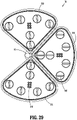
- actuator assembly 214 of inner housing assembly 210 includes a first set of cable actuator assemblies 216, a second set of cable actuator assemblies 218, and an axial actuator assembly 220 that are secured to a support plate 222.
- adjacent cable actuator assemblies 216, 218 may be disposed out of phase and/or offset from one another by, for example, 90 degrees (e.g., orthogonal to one another), and with axial actuator assembly 220 centered between first and second sets of cable actuator assemblies 216, 218 to conserve space and reduce size requirements of inner housing assembly 210.
- Support plate 222 defines bores 222a for supporting cable and actuator assemblies 216, 218, and 220 therein, and cable passages 222b for receiving cables 224 of cable actuator assembles 216, 218 therethrough.
- first set of cable actuator assemblies 216 are shown to be longer than second set of cable actuator assemblies 218, and the second set of cable actuator assemblies 218 is otherwise substantially the same as the first set of cable actuator assemblies 218. Indeed, the first and second set of cable actuator assemblies 216, 218 may have any suitable length.
- Axial actuator assembly 220 is coupled to a drive cable 226 that extends through a tube 228 extending from support plate 222 that couples to elongated shaft assembly 204.
- Each cable actuator assembly 216, 218 of actuator assembly 214 includes a spindle 230, an upper crank 232, a lower crank 234, an upper pin 236a, a lower pin 236b, an upper bearing 238a, and a lower bearing 238b.
- Spindles 230 of actuator assemblies 216, 218 include an upper peg 230a extending from a first end thereof and a lower peg 230b extending from a second end thereof. Upper and lower pegs 230a, 230b secure to upper and lower bearings 238a, 238b, respectively. Upper peg 230a is engageable with movable drive unit 18 to enable movable drive unit 18 to impart rotational drive force on spindles 230 (e.g., through drive couplers -not shown- of drive unit 18).
- Each spindle 230 further defines an upper pin passage 230c and a lower pin passage 230d that extend transversely through spindle 230 at longitudinally spaced-apart locations and are positioned to receive upper and lower pins 236a, 236b, respectively, in a transverse (e.g., an orthogonal) relationship with spindle 230.
- Lower crank 234 of each cable actuator assembly 216, 218 defines a spindle passage 234a longitudinally and centrally therethrough for receiving spindle 230 therethrough.
- Lower crank 234 further defines a spiral channel 234b in an outer surface thereof.
- Spiral channel 234b slidably receives lower pin 236b of spindle 230 to enable lower crank 234 to axially slide along a lower portion of spindle 230, as indicated by arrows "AA” (e.g., distally) and "AB” (e.g., proximally) when spindle 230 rotates about spindle axis "SA” relative to lower crank 234, as indicated by arrows "RA” (e.g., clockwise) and "RB” (e.g., counterclockwise) shown in FIGS.
- AA e.g., distally
- AB e.g., proximally
- Lower crank 234 further includes a spine 234c that extends longitudinally along the outer surface of lower crank 234.
- Spine 234c defines cable channels 234d, 234e longitudinally therethrough that support cables 224.
- a first cable 224a of cables 224 is secured to lower crank 234 (e.g., via cable channel 234e) and translates in the same direction and simultaneously with lower crank 234 (e.g., as indicated by arrows "AA" and "AB").
- a second cable 224b of cables 224 is slidably movable through cable channel 234d of lower crank 234 and relative to lower yoke 234 as upper crank 232 translates relative to spindle 230.
- Second cable 224b is secured to upper crank 232 and movable with upper crank 232.
- Upper crank 232 of each cable actuator assembly 216, 218 is substantially like lower crank 234 but includes a spiral channel 232a that turns along the outer surface thereof in an opposite direction as compared to spiral channel 234b of lower crank 234. And spiral channel 232a of upper crank 232 slidably receives upper pin 236a of spindle 230 to axially slide upper crank 232 along an upper portion of spindle 230, as indicated by arrows "BA” (e.g., proximally) and "BB” (e.g., distally), when spindle 230 rotates about spindle axis "SA” and relative to upper crank 232, as indicated by arrows "RA” (e.g., clockwise) and "RB” (e.g., counterclockwise) shown in FIGS.
- BA e.g., proximally
- BB e.g., distally
- Upper and lower cranks 234, 236 are positioned to translate in opposite axial directions relative to one another along spindle axis "SA" as upper and lower cranks 234, 236 rotate about spindle 230 and spindle axis "SA.”
- upper crank 232 further includes a spine 232x that supports and is secured to second cable 224b to enable second cable 224b to translate with upper crank 232 and relative to lower crank 234, as indicated by arrows "BA” and "BB.”
- Upper crank 232 is separate and disconnected from first cable 224a.
- Axial actuator assembly 220 is substantially like cable actuator assemblies 216, 218, but includes a spindle 230, an upper crank 232, an upper pin 236a, an upper bearing 238a, and a lower bearing 238b (e.g., there is no lower crank or lower pin).
- Upper crank 232 is coupled to drive cable 226 and axially translatable upon rotation of spindle 230 thereof to translate drive cable 226 and impart axial drive force through drive cable 226 to, for example, end effector 106.
- surgical instrument system 70 of robotic surgical system 10 includes insertion tube 16 and a plurality of surgical instruments 300 that is insertable through insertion tube 16. Although only three surgical instruments 300 are shown, surgical instrument system 70 can include any number and/or type of surgical instruments such as graspers 26 and endoscope 28 as noted above.
- surgical instrument 300 of surgical instrument system 70 defines a longitudinal axis "L3" and includes an instrument cassette assembly 302 on a proximal end portion thereof and an elongated shaft assembly 304 that extends from instrument cassette assembly 302 to an end effector 306 ( FIG. 7 ) supported on a distal end portion of elongated shaft assembly 304.
- End effector 306 is actuatable by instrument cassette assembly 302 for effectuating a surgical procedure.
- actuating end effector 306 can cause end effector 306 to, for example, articulate, pivot, clamp, rotate, etc. relative to the longitudinal axis "L3" of surgical instrument 300 for repositioning end effector 306 and/or for treating tissue "T" of the patient "P” as noted above with respect to end effector 106 (see FIGS. 2-4 ).
- instrument cassette assembly 302 of surgical instrument 300 includes an outer housing assembly 308 that supports an ID board 310, a latch release mechanism 312 having a button release 312a for selectively removing surgical instrument from movable drive unit 18, and an electrosurgical socket 314 for selectively connecting to an electrosurgical energy source via an electrosurgical cable (not shown).
- Instrument cassette assembly 302 further includes an actuator system 316 supported within outer housing assembly 308 for actuating end effector 306.
- actuator system 316 includes a plurality of cable actuator assemblies 318 and a drive actuator assembly 320.
- the drive actuator assembly 320 includes an axial actuator assembly 322 and a rotation actuator assembly 324.
- each cable actuator assembly 318 of the actuator system 316 includes a crank 330, an upper slider 332, a lower slider 334, and a driver 336.
- the upper slider 332 secured to an upper surface of crank body 330x, via a first pin 333a, on a first side of crank body 330x
- the lower slider 334 secured to a lower surface of crank body 330x, via a second pin 333b, on a second side of crank body 330x.
- Crank body 330x defines a first opening 330a on the first side of crank body 330x that receives a lower portion of the first pin 333a and a second opening 330b on the second side of crank body 330x that receives an upper portion of the second pin 333b.
- Upper slider 332 defines an elongated pin slot 332a that receives an upper portion of the first pin 333a and lower slider 334 defines an elongated pin slot 334a that receives a lower portion of the second pin 333b.
- Upper and lower sliders 332, 334 further define ferrule openings 335 that support ferrules (not shown) therein for securing cables 338 of cable actuator assembly 318 to respective upper and lower sliders 332, 334.
- Crank 330 further includes a drive shaft 330c that extends from the upper and lower surfaces of crank body 330x and nonrotatably supports driver 336 so that rotation of driver 336 imparts rotational force to crank 330.
- each cable actuator assembly 318 may be provided in the form of a rack and pinion arrangement.
- crank 330 may be a pinion
- upper slider 332 and lower slider 334 are in the form of racks so that teeth of these respect rack and pinion feature engage one another.
- upper and lower sliders 332, 334 may be disposed in the same plane as one another (e.g., vertically aligned or in registration), and/or vertically offset from one another such that one is higher and/or lower than the other along a vertical or central axis (not explicitly shown) extending through a center of crank 330.
- crank 330 As seen in FIGS. 34-36 , rotation of driver 336 in a first direction (e.g., counterclockwise), as indicated by arrow "RCC,” rotates crank 330 such that first pin 333a moves inwardly along elongated pin slot 332a of upper slider 332 to an actuated position and second pin 333b moves inwardly along elongated pin slot 334a of lower slider 334 to an actuated position.
- first direction e.g., counterclockwise
- crank 330 and first pin 333a cause upper slider 332 to translate distally as indicated by arrow "DCC” while crank 330 and second pin 333b cause lower slider 334 to translate proximally as indicated by arrow “PCC.”
- Rotation of driver 336 in a second direction opposite to the first direction (e.g., clockwise), as indicated by arrow “RC” causes crank 330 to rotate such that first and second ins 33a, 33b move to the actuated position within respective elongated pin slots 332a, 334a of upper and lower sliders 332, 334 and drive upper slider 332 in a proximal direction, as indicated by arrow "PC,” and lower slider 334 in a distal direction, as indicated by arrow “DC.”
- cables 338 secured thereto translate with the respective upper and lower sliders 332, 334.
- a first cable 338a of cables 338 secured to upper slider 332 translates distally (or proximally) with upper slider 332, and vice versa.
- a second cable 338b of cables 338 secured to lower slider 334 translates proximally (or distally) with lower slider 334, and vice versa.
- drive actuator assembly 320 of actuator system 316 includes an actuator housing 321 having a first housing portion 321a and a second housing portion 321b that define actuator mounts 321c, 321d for supporting the axial actuator assembly 322 and the rotation actuator assembly 324 between the first and second housing portions 321a, 321b.
- Second housing portion 312b further includes a mounting protrusion 312e extending from a sidewall thereof.
- Rotation actuator assembly 324 of drive actuator assembly 320 includes an input spool 340, an output spool 342, a rotation cable 344 that couples to (e.g., wraps around) input and output spools 340, 342, bearings 346a, 346b, and a driver 348 that nonrotatably couples to input spool 340.
- Cable 344 may have any number of windings about input and output spools 340, 342 to enable rotational force to be transferred between input and output spools 340, 342.
- elongated shaft assembly 304 of surgical instrument 300 includes an inner shaft 304a to which output spool 342 nonrotatably couples, and which is coupled to actuator housing 321 by a shaft bearing 343.
- Output spool 342 imparts rotational force to inner shaft 304a from input spool 340 as rotation cable 344 rotates output spool 342 about inner shaft axis "ISA,” as indicated by arrow “OS,” (as rotation cable 344 translates-see arrows “T1” and “T2") in response to rotation of driver 348 about driver axis "DA,” as indicated by arrow "IS.”
- Axial actuator assembly 322 of drive actuator assembly 320 includes a clevis 350, a threaded nut 352 mounted to clevis 350 via pins 352a thereof, an upper bearing 354, a lower bearing 356, a threaded driver 357 having threads 357a, and a cable pivot 358.
- Threads 357a of threaded driver 357 are threadedly engageable with threads 352b of threaded nut 352 to enable threaded nut 352 to translate along threaded driver 357, as indicated by arrows "N1" and “N2,” when threaded driver 357 is rotated, as indicated by arrows "TD1” and “TD2” (e.g., clockwise and/or counterclockwise about axis "TDA.”
- Clevis 350 defines a nut mount 350a on a first end thereof that defines pin holes 350b therethrough for receiving pins 352a of threaded nut 352 therein.
- Clevis 350 further defines a protuberance hole 350c that receives mounting protrusion 312e of second housing portion 312b for securing clevis 350 to actuator housing 321.
- a second end of clevis 350 defines a cable pivot channel 350d for receiving cable pivot 358 and an axial drive cable 360 therein.
- Axial drive cable 360 is coupled to cable pivot 358 on a first end thereof and extends through inner shaft 304a to enable a second end of axial drive cable 360 to secure to end effector 306 for imparting axial drive force on end effector 306.
- the first end of clevis 350 pivots about pins 352a and mounting protrusion 312e, relative to threaded nut 352, such that the second end of clevis 350 moves axial drive cable 360 between an extended position ( FIG. 42 ) and a retracted position ( FIG. 41 ), as indicated by arrows "ZZ" and "YY.”
- the second end of clevis 350 also pivot relative to cable pivot 350 as axial drive cable 360 is moved between the extended and retracted positions to impart axial force to end effector 306.
- the disclosed structure can include any suitable mechanical, electrical, and/or chemical components for operating the disclosed system or components thereof.
- electrical components can include, for example, any suitable electrical and/or electromechanical, and/or electrochemical circuitry, which may include or be coupled to one or more printed circuit boards.
- the disclosed computing devices can include, for example, a "controller,” “processor,” “digital processing device” and like terms, and which are used to indicate a microprocessor or central processing unit (CPU).
- the CPU is the electronic circuitry within a computer that carries out the instructions of a computer program by performing the basic arithmetic, logical, control and input/output (I/O) operations specified by the instructions, and by way of non-limiting examples, include server computers.
- the controller includes an operating system configured to perform executable instructions.
- the operating system is, for example, software, including programs and data, which manages hardware of the disclosed apparatus and provides services for execution of applications for use with the disclosed apparatus.
- suitable server operating systems include, by way of non-limiting examples, FreeBSD, OpenBSD, NetBSD ® , Linux, Apple ® Mac OS X Server ® , Oracle ® Solaris ® , Windows Server ® , and Novell ® NetWare ® .
- the operating system is provided by cloud computing.
- controller may be used to indicate a device that controls the transfer of data from a computer or computing device to a peripheral or separate device and vice versa, and/or a mechanical and/or electromechanical device (e.g., a lever, knob, etc.) that mechanically operates and/or actuates a peripheral or separate device.
- a mechanical and/or electromechanical device e.g., a lever, knob, etc.
- the controller includes a storage and/or memory device.
- the storage and/or memory device is one or more physical apparatus used to store data or programs on a temporary or permanent basis.
- the controller includes volatile memory and requires power to maintain stored information.
- the controller includes non-volatile memory and retains stored information when it is not powered.
- the non-volatile memory includes flash memory.
- the non-volatile memory includes dynamic random-access memory (DRAM).
- the non-volatile memory includes ferroelectric random-access memory (FRAM).
- the non-volatile memory includes phase-change random access memory (PRAM).
- the controller is a storage device including, by way of non-limiting examples, CD-ROMs, DVDs, flash memory devices, magnetic disk drives, magnetic tapes drives, optical disk drives, and cloud-computing-based storage.
- the storage and/or memory device is a combination of devices such as those disclosed herein.
- the memory can be random access memory, read-only memory, magnetic disk memory, solid state memory, optical disc memory, and/or another type of memory.
- the memory can be separate from the controller and can communicate with the processor through communication buses of a circuit board and/or through communication cables such as serial ATA cables or other types of cables.
- the memory includes computer-readable instructions that are executable by the processor to operate the controller.
- the controller may include a wireless network interface to communicate with other computers or a server.
- a storage device may be used for storing data.
- the processor may be, for example, without limitation, a digital signal processor, a microprocessor, an ASIC, a graphics processing unit ("GPU"), field-programmable gate array (“FPGA”), or a central processing unit (“CPU”).
- the memory stores suitable instructions and/or applications, to be executed by the processor, for receiving the sensed data (e.g., sensed data from camera), accessing storage device of the controller, generating a raw image based on the sensed data, comparing the raw image to a calibration data set, identifying an object based on the raw image compared to the calibration data set, transmitting object data to a post-processing unit, and displaying the object data to a graphic user interface.
- a controller may be remote from the disclosed structure (e.g., on a remote server), and accessible by the disclosed structure via a wired or wireless connection. In aspects where the controller is remote, it is contemplated that the controller may be accessible by, and connected to, multiple structures and/or components of the disclosed system.
- application may include a computer program designed to perform functions, tasks, or activities for the benefit of a user.
- Application may refer to, for example, software running locally or remotely, as a standalone program or in a web browser, or other software which would be understood by one skilled in the art to be an application.
- An application may run on the disclosed controllers or on a user device, including for example, on a mobile device, an IOT device, or a server system.
- the controller includes a display to send visual information to a user.
- the display is a cathode ray tube (CRT).
- the display is a liquid crystal display (LCD).
- the display is a thin film transistor liquid crystal display (TFT-LCD).
- the display is an organic light emitting diode (OLED) display.
- OLED organic light emitting diode
- on OLED display is a passive-matrix OLED (PMOLED) or active-matrix OLED (AMOLED) display.
- the display is a plasma display.
- the display is a video projector.
- the display is interactive (e.g., having a touch screen) that can detect user interactions/gestures/responses and the like.
- the display is a combination of devices such as those disclosed herein.
- the controller may include or be coupled to a server and/or a network.
- server includes “computer server,” “central server,” “main server,” and like terms to indicate a computer or device on a network that manages the disclosed apparatus, components thereof, and/or resources thereof.
- network can include any network technology including, for instance, a cellular data network, a wired network, a fiber-optic network, a satellite network, and/or an IEEE 802.11a/b/g/n/ac wireless network, among others.
- the controller can be coupled to a mesh network.
- a “mesh network” is a network topology in which each node relays data for the network. All mesh nodes cooperate in the distribution of data in the network. It can be applied to both wired and wireless networks.
- Wireless mesh networks can be considered a type of "Wireless ad hoc" network.
- wireless mesh networks are closely related to Mobile ad hoc networks (MANETs).
- MANETs are not restricted to a specific mesh network topology, Wireless ad hoc networks or MANETs can take any form of network topology.
- Mesh networks can relay messages using either a flooding technique or a routing technique.
- the message With routing, the message is propagated along a path by hopping from node to node until it reaches its destination.
- the network must allow for continuous connections and must reconfigure itself around broken paths, using self-healing algorithms such as Shortest Path Bridging.
- Self-healing allows a routing-based network to operate when a node breaks down or when a connection becomes unreliable.
- the network is typically quite reliable, as there is often more than one path between a source and a destination in the network. This concept can also apply to wired networks and to software interaction.
- a mesh network whose nodes are all connected to each other is a fully connected network.
- the controller may include one or more modules.
- module and like terms are used to indicate a self-contained hardware component of the central server, which in turn includes software modules.
- a module is a part of a program. Programs are composed of one or more independently developed modules that are not combined until the program is linked. A single module can contain one or several routines, or sections of programs that perform a particular task.
- the controller includes software modules for managing various aspects and functions of the disclosed system or components thereof.
- the disclosed structure may also utilize one or more controllers to receive various information and transform the received information to generate an output.
- the controller may include any type of computing device, computational circuit, or any type of processor or processing circuit capable of executing a series of instructions that are stored in memory.
- the controller may include multiple processors and/or multicore central processing units (CPUs) and may include any type of processor, such as a microprocessor, digital signal processor, microcontroller, programmable logic device (PLD), field programmable gate array (FPGA), or the like.
- the controller may also include a memory to store data and/or instructions that, when executed by the one or more processors, cause the one or more processors to perform one or more methods and/or algorithms.
- a phrase in the form “A or B” means “(A), (B), or (A and B).
- a phrase in the form “at least one of A, B, or C” means "(A); (B); (C); (A and B); (A and C); (B and C); or (A, B, and C).
- programming language and "computer program,” as used herein, each include any language used to specify instructions to a computer, and include (but is not limited to) the following languages and their derivatives: Assembler, Basic, Batch files, BCPL, C, C+, C++, Delphi, Fortran, Java, JavaScript, machine code, operating system command languages, Pascal, Perl, PL1, scripting languages, Visual Basic, metalanguages which themselves specify programs, and all first, second, third, fourth, fifth, or further generation computer languages. Also included are database and other data schemas, and any other meta-languages.
- Securement of any of the components of the disclosed devices may be effectuated using known securement techniques such welding, crimping, gluing, fastening, etc.
Landscapes
- Health & Medical Sciences (AREA)
- Surgery (AREA)
- Life Sciences & Earth Sciences (AREA)
- Engineering & Computer Science (AREA)
- Heart & Thoracic Surgery (AREA)
- Biomedical Technology (AREA)
- Nuclear Medicine, Radiotherapy & Molecular Imaging (AREA)
- Medical Informatics (AREA)
- Molecular Biology (AREA)
- Animal Behavior & Ethology (AREA)
- General Health & Medical Sciences (AREA)
- Public Health (AREA)
- Veterinary Medicine (AREA)
- Robotics (AREA)
- Pathology (AREA)
- Oral & Maxillofacial Surgery (AREA)
- Surgical Instruments (AREA)
Applications Claiming Priority (2)
| Application Number | Priority Date | Filing Date | Title |
|---|---|---|---|
| US202163188554P | 2021-05-14 | 2021-05-14 | |
| US17/686,749 US20220361971A1 (en) | 2021-05-14 | 2022-03-04 | Instrument cassette assemblies for robotic surgical instruments |
Publications (1)
| Publication Number | Publication Date |
|---|---|
| EP4088678A1 true EP4088678A1 (de) | 2022-11-16 |
Family
ID=82019282
Family Applications (1)
| Application Number | Title | Priority Date | Filing Date |
|---|---|---|---|
| EP22173358.7A Pending EP4088678A1 (de) | 2021-05-14 | 2022-05-13 | Instrumentenkassetten für chirurgische roboterinstrumente |
Country Status (3)
| Country | Link |
|---|---|
| US (1) | US20220361971A1 (de) |
| EP (1) | EP4088678A1 (de) |
| CN (1) | CN115337107A (de) |
Citations (5)
| Publication number | Priority date | Publication date | Assignee | Title |
|---|---|---|---|---|
| US20080087871A1 (en) * | 2006-10-12 | 2008-04-17 | Schena Bruce M | Compact Cable Tension Tender Device |
| US20140005681A1 (en) * | 2012-06-29 | 2014-01-02 | Ethicon Endo-Surgery, Inc. | Ultrasonic surgical instruments with control mechanisms |
| US20140257333A1 (en) * | 2013-03-07 | 2014-09-11 | Intuitive Surgical Operations, Inc. | Hybrid manual and robotic interventional instruments and methods of use |
| US20190150904A1 (en) * | 2013-06-19 | 2019-05-23 | Titan Medical Inc. | Articulated tool positioner and system employing same |
| US20210137618A1 (en) * | 2017-04-14 | 2021-05-13 | Medical Microinstruments S.p.A. | Robotic microsurgical assembly |
-
2022
- 2022-03-04 US US17/686,749 patent/US20220361971A1/en active Pending
- 2022-05-07 CN CN202210494190.1A patent/CN115337107A/zh active Pending
- 2022-05-13 EP EP22173358.7A patent/EP4088678A1/de active Pending
Patent Citations (5)
| Publication number | Priority date | Publication date | Assignee | Title |
|---|---|---|---|---|
| US20080087871A1 (en) * | 2006-10-12 | 2008-04-17 | Schena Bruce M | Compact Cable Tension Tender Device |
| US20140005681A1 (en) * | 2012-06-29 | 2014-01-02 | Ethicon Endo-Surgery, Inc. | Ultrasonic surgical instruments with control mechanisms |
| US20140257333A1 (en) * | 2013-03-07 | 2014-09-11 | Intuitive Surgical Operations, Inc. | Hybrid manual and robotic interventional instruments and methods of use |
| US20190150904A1 (en) * | 2013-06-19 | 2019-05-23 | Titan Medical Inc. | Articulated tool positioner and system employing same |
| US20210137618A1 (en) * | 2017-04-14 | 2021-05-13 | Medical Microinstruments S.p.A. | Robotic microsurgical assembly |
Also Published As
| Publication number | Publication date |
|---|---|
| CN115337107A (zh) | 2022-11-15 |
| US20220361971A1 (en) | 2022-11-17 |
Similar Documents
| Publication | Publication Date | Title |
|---|---|---|
| US11439458B2 (en) | Robotic bi-polar instruments | |
| US10945798B2 (en) | Methods, systems, and devices for causing end effector motion with a robotic surgical system | |
| JP7074799B2 (ja) | クイックリリースエンドエフェクターおよび関連するシステムおよび方法 | |
| US20180206904A1 (en) | Articulating electrosurgical tools | |
| Arkenbout et al. | A state of the art review and categorization of multi-branched instruments for NOTES and SILS | |
| US20180161110A1 (en) | Surgical Tool and Robotic Surgical System Interfaces | |
| US20240148376A1 (en) | Small diameter linear surgical stapling apparatus | |
| US10433920B2 (en) | Surgical tool and robotic surgical system interfaces | |
| US10588704B2 (en) | Surgical tool and robotic surgical system interfaces | |
| US20180161118A1 (en) | Surgical Tool and Robotic Surgical System Interfaces | |
| EP4088678A1 (de) | Instrumentenkassetten für chirurgische roboterinstrumente | |
| KR102455138B1 (ko) | 수술 도구 리스트 | |
| US20210386424A1 (en) | Sealed electrical connection between surgical loading unit and adapter | |
| EP3922193A1 (de) | Abgedichtete elektrische verbindung zwischen chirurgischer ladeeinheit und adapter | |
| US20220378533A1 (en) | Control drive assemblies for robotic surgical systems | |
| US20210322116A1 (en) | Surgical systems and methods for robotic actuation of continuum joints | |
| US20240065538A1 (en) | Endoscopic lens cleaning in a robotic surgical procedure | |
| WO2023172759A1 (en) | Robotic surgical system with control drive assembly for single port surgical techniques | |
| EP4370055A1 (de) | Sterile adapteranordnungen für robotische chirurgische systeme | |
| WO2023215982A1 (en) | Robotic surgical system with control drive assembly for single port surgical techniques | |
| US20240173089A1 (en) | Robotic remote center of motion with active portal/trocar manipulation | |
| US11717300B2 (en) | Surgical stapling apparatus with integrated visualization | |
| US20230248457A1 (en) | Controller arrangements for robotic surgical systems | |
| WO2022221485A1 (en) | Robotic remote center of motion with active portal/trocar manipulation | |
| WO2023220809A1 (en) | Robotic surgical instruments |
Legal Events
| Date | Code | Title | Description |
|---|---|---|---|
| PUAI | Public reference made under article 153(3) epc to a published international application that has entered the european phase |
Free format text: ORIGINAL CODE: 0009012 |
|
| STAA | Information on the status of an ep patent application or granted ep patent |
Free format text: STATUS: REQUEST FOR EXAMINATION WAS MADE |
|
| 17P | Request for examination filed |
Effective date: 20220513 |
|
| AK | Designated contracting states |
Kind code of ref document: A1 Designated state(s): AL AT BE BG CH CY CZ DE DK EE ES FI FR GB GR HR HU IE IS IT LI LT LU LV MC MK MT NL NO PL PT RO RS SE SI SK SM TR |
|
| RAP1 | Party data changed (applicant data changed or rights of an application transferred) |
Owner name: COVIDIEN LP |