EP4088552B1 - Deaktivierung der steuerung einer beleuchtungsvorrichtung durch eine lichtsteuerungsvorrichtung in einem abfragemodus - Google Patents
Deaktivierung der steuerung einer beleuchtungsvorrichtung durch eine lichtsteuerungsvorrichtung in einem abfragemodus Download PDFInfo
- Publication number
- EP4088552B1 EP4088552B1 EP20821306.6A EP20821306A EP4088552B1 EP 4088552 B1 EP4088552 B1 EP 4088552B1 EP 20821306 A EP20821306 A EP 20821306A EP 4088552 B1 EP4088552 B1 EP 4088552B1
- Authority
- EP
- European Patent Office
- Prior art keywords
- light control
- lighting
- control device
- lighting system
- user
- Prior art date
- Legal status (The legal status is an assumption and is not a legal conclusion. Google has not performed a legal analysis and makes no representation as to the accuracy of the status listed.)
- Active
Links
Images


Classifications
-
- H—ELECTRICITY
- H05—ELECTRIC TECHNIQUES NOT OTHERWISE PROVIDED FOR
- H05B—ELECTRIC HEATING; ELECTRIC LIGHT SOURCES NOT OTHERWISE PROVIDED FOR; CIRCUIT ARRANGEMENTS FOR ELECTRIC LIGHT SOURCES, IN GENERAL
- H05B47/00—Circuit arrangements for operating light sources in general, i.e. where the type of light source is not relevant
- H05B47/10—Controlling the light source
- H05B47/16—Controlling the light source by timing means
-
- G—PHYSICS
- G08—SIGNALLING
- G08C—TRANSMISSION SYSTEMS FOR MEASURED VALUES, CONTROL OR SIMILAR SIGNALS
- G08C17/00—Arrangements for transmitting signals characterised by the use of a wireless electrical link
-
- H—ELECTRICITY
- H05—ELECTRIC TECHNIQUES NOT OTHERWISE PROVIDED FOR
- H05B—ELECTRIC HEATING; ELECTRIC LIGHT SOURCES NOT OTHERWISE PROVIDED FOR; CIRCUIT ARRANGEMENTS FOR ELECTRIC LIGHT SOURCES, IN GENERAL
- H05B47/00—Circuit arrangements for operating light sources in general, i.e. where the type of light source is not relevant
- H05B47/10—Controlling the light source
- H05B47/175—Controlling the light source by remote control
- H05B47/19—Controlling the light source by remote control via wireless transmission
-
- G—PHYSICS
- G08—SIGNALLING
- G08C—TRANSMISSION SYSTEMS FOR MEASURED VALUES, CONTROL OR SIMILAR SIGNALS
- G08C2201/00—Transmission systems of control signals via wireless link
- G08C2201/30—User interface
-
- G—PHYSICS
- G08—SIGNALLING
- G08C—TRANSMISSION SYSTEMS FOR MEASURED VALUES, CONTROL OR SIMILAR SIGNALS
- G08C2201/00—Transmission systems of control signals via wireless link
- G08C2201/30—User interface
- G08C2201/31—Voice input
-
- G—PHYSICS
- G08—SIGNALLING
- G08C—TRANSMISSION SYSTEMS FOR MEASURED VALUES, CONTROL OR SIMILAR SIGNALS
- G08C2201/00—Transmission systems of control signals via wireless link
- G08C2201/30—User interface
- G08C2201/34—Context aware guidance
-
- G—PHYSICS
- G08—SIGNALLING
- G08C—TRANSMISSION SYSTEMS FOR MEASURED VALUES, CONTROL OR SIMILAR SIGNALS
- G08C2201/00—Transmission systems of control signals via wireless link
- G08C2201/50—Receiving or transmitting feedback, e.g. replies, status updates, acknowledgements, from the controlled devices
-
- G—PHYSICS
- G08—SIGNALLING
- G08C—TRANSMISSION SYSTEMS FOR MEASURED VALUES, CONTROL OR SIMILAR SIGNALS
- G08C2201/00—Transmission systems of control signals via wireless link
- G08C2201/90—Additional features
- G08C2201/91—Remote control based on location and proximity
-
- G—PHYSICS
- G08—SIGNALLING
- G08C—TRANSMISSION SYSTEMS FOR MEASURED VALUES, CONTROL OR SIMILAR SIGNALS
- G08C2201/00—Transmission systems of control signals via wireless link
- G08C2201/90—Additional features
- G08C2201/93—Remote control using other portable devices, e.g. mobile phone, PDA, laptop
-
- Y—GENERAL TAGGING OF NEW TECHNOLOGICAL DEVELOPMENTS; GENERAL TAGGING OF CROSS-SECTIONAL TECHNOLOGIES SPANNING OVER SEVERAL SECTIONS OF THE IPC; TECHNICAL SUBJECTS COVERED BY FORMER USPC CROSS-REFERENCE ART COLLECTIONS [XRACs] AND DIGESTS
- Y02—TECHNOLOGIES OR APPLICATIONS FOR MITIGATION OR ADAPTATION AGAINST CLIMATE CHANGE
- Y02B—CLIMATE CHANGE MITIGATION TECHNOLOGIES RELATED TO BUILDINGS, e.g. HOUSING, HOUSE APPLIANCES OR RELATED END-USER APPLICATIONS
- Y02B20/00—Energy efficient lighting technologies, e.g. halogen lamps or gas discharge lamps
- Y02B20/40—Control techniques providing energy savings, e.g. smart controller or presence detection
Definitions
- the invention relates to a system for controlling a lighting system, said lighting system comprising a light control device and a lighting device, said light control device being used for controlling said lighting device.
- the invention further relates to a method of controlling a lighting system, said lighting system comprising a light control device and a lighting device, said light control device being used for controlling said lighting device.
- the invention also relates to a computer program product enabling a computer system to perform such a method.
- each light control device is typically programmed by its owner.
- each button is assigned to a room and multiple functions can be programmed for a button, e.g. scene cycling, light source on-off, and dimming, and a user can have multiple of these buttons with different behaviors.
- WO 2018/007450A1 discloses an example of a programmable light control device.
- WO 2018/007450A1 discloses a method of programming a respective rule for controlling lighting in each of one or more zones each being occupiable by a user.
- the rule specifies how the illumination emitted by an illumination source is to be controlled as a function of a user interaction. After actuating an actuator in a certain zone, the user can select one or more illumination sources arranged to illuminate this zone, which is then programmed into a memory as a rule.
- US 2015/373796 A1 discloses a LED driver that can be configured to match the voltage and/or current requirements of various LED loads, wherein a wireless remote controller may operate the LED driver.
- buttons or labels are often used for identifying the functionality of each button, but this requires dedicated buttons or labels for each function, which is not practical for programmable buttons.
- buttons with different functions may result in the user getting confused and using the wrong button or using the right button in the wrong way, e.g. double press the living room button to scene cycle, because that functionality is programmed in the kitchen button, whereas the living room button is programmed to dim on double press.
- a system for controlling a lighting system comprising a light control device and a lighting device, said light control device being used for controlling said lighting device, comprises at least one input interface, at least one output interface, and at least one processor configured to receive, via said at least one input interface, user input representing a request to activate a query mode, transmit, via said at least one output interface, a command to said lighting system, said command instructing said lighting system to temporarily disable control of said lighting device by said light control device, receive, via said at least one input interface, control information from said lighting system, said control information describing a user interaction with said light control device and/or describing a function corresponding to said user interaction, render, via said at least one output interface, audio and/or visual information describing said function corresponding to said user interaction to said user, and transmit, via said at least one output interface, a further command to said lighting system, said further command instructing said lighting system to enable control of said lighting device by said light control device.
- Said at least one processor may be configured to render, via a display and/or a speaker of a mobile device and/or a voice assistant, said audio and/or visual information describing said function.
- the voice assistant may be accessed on the mobile device or on a smart speaker like the Amazon Echo, for example.
- the user may indicate to the system his intention to enquire about the functionality of a button of a specific light control device.
- the system temporarily disables all physical controls of that specific light control device with respect to controlling associated lighting devices and renders information describing this functionality after the user interacts with that specific light control device, e.g. presses a button of that specific light control device.
- a user may not know which light control device he is looking at and may indicate that he would like to enquire about the functionality of an unknown button.
- the system temporarily disables all physical controls of all light control devices within a defined scope (e.g. all devices in a room or home) with respect to controlling associated lighting devices, but other light control devices can still be used to control associated lighting devices. After the system detects user interaction with a light control device, it assumes that this is the light control device the user wants to enquire about.
- Said command and said further command may be transmitted to said light control device and said control information may be received from said light control device.
- An alternative is to transmit the command and further command to a bridge and to receive the control information from the bridge.
- This alternative allows the light control device to be simpler. For example, the light control device only needs to transmit control information describing a user interaction with the light control device to the bridge without knowing what function is associated with this user interaction.
- Said control information may comprise an identifier of said light control device and describe a user interaction with said light control device and said at least one processor may be configured to determine a description of said function from said identifier and said description of said user interaction. This beneficial if the control information does not comprise the description of the function.
- Said control information may describe a user interaction with a button or rotary switch of said light control device and/or a function corresponding to said user interaction with said button or rotary switch of said light control device. Buttons and rotary switches are often used on light control devices.
- Said lighting system may comprise a plurality of light control devices and said at least one processor may be configured to determine a subset of said plurality of light control devices, said subset of light control devices comprising said light control device and being used to control a set of lighting devices, said set of lighting devices comprising said lighting device, transmit, via said at least one output interface, one or more commands to said lighting system, said one or more commands instructing said lighting system to temporarily disable control of said set of lighting devices by said subset of light control devices, and transmit, via said at least one output interface, one or more further commands to said lighting system, said one or more further commands instructing said lighting system to enable control of said set of lighting devices by said subset of light control devices.
- said at least one processor may be configured to determine a subset of said plurality of light control devices, said subset of light control devices comprising said light control device and being used to control a set of lighting devices, said set of lighting devices comprising said lighting device, transmit, via said at least one output interface, one or more commands to said lighting system, said one
- Said at least one processor may be configured to determine said subset of said plurality of light control devices based on said user input. For example, the user may be able to select the subset from a list of commissioned light control devices, e.g. in an app.
- Said at least one processor may be configured to determine a location of said user and determine said subset of said plurality of light control devices based on said location. This is beneficial if the user does not know which light control device he is looking at. Typically, a user will want information on the light control device(s) closest to him. If the location of the user is known, this may also be used to select on which device to render the audio and/or visual information describing the function corresponding to the user interaction. For example, if a smart speaker, e.g. an Amazon Echo speaker, is in the same room as the user, the audio and/or visual information may be rendered on this smart speaker. If not, the audio and/or visual information may be rendered on the user's mobile phone, for example. Alternatively, the closest device able to render audio and/or visual information describing the function corresponding to the user interaction may be selected, for example.
- a smart speaker e.g. an Amazon Echo speaker
- Said at least one processor may be configured to start a timer upon receiving said user input and transmit, via said at least one output interface, said further command upon expiry of said timer. This allows the query mode to be ended automatically, without requiring user interaction.
- Said at least one processor may be configured to receive, via said at least one input interface, further user input representing a request to deactivate said query mode and transmit, via said at least one output interface, said further command upon receiving said further user input. This allows the user to end the query mode earlier, without having to wait for the query mode to end automatically, or this may be used instead of an automatically ending query mode.
- Said at least one processor may be configured to control, via said at least one output interface, a further lighting device of said one or more lighting devices based on said received control information. This may be used to enhance the rendering of the description of the function by demonstrating a light scene associated with an interaction/physical control on a subset (e.g. one) of the lighting devices associated with the light scene or on a different lighting device.
- Said at least one processor may be configured to display, via said at least one output interface, an animation demonstrating said function.
- said at least one processor may be configured to display, via said at least one output interface, a virtual room comprising a virtual representation of said at least one lighting device and said animation superimposed over said virtual room. This enhances the rendering of the description of the function.
- a method of controlling a lighting system comprises receiving user input representing a request to activate a query mode, transmitting a command to said lighting system, said command instructing said lighting system to temporarily disable control of said at least one lighting device by said light control device, receiving control information from said lighting system, said control information describing a user interaction with said light control device and/or describing a function corresponding to said user interaction, rendering audio and/or visual information describing said function corresponding to said user interaction to said user, and transmitting a further command to said lighting system, said further command instructing said lighting system to enable control of said lighting device by said light control device.
- Said method may be performed by software running on a programmable device. This software may be provided as a computer program product.
- a computer program for carrying out the methods described herein, as well as a non-transitory computer readable storage-medium storing the computer program are provided.
- a computer program may, for example, be downloaded by or uploaded to an existing device or be stored upon manufacturing of these systems.
- a non-transitory computer-readable storage medium stores at least one software code portion, the software code portion, when executed or processed by a computer, being configured to perform executable operations for controlling a lighting system, said lighting system comprising a light control device and a lighting device, said light control device being used for controlling said lighting device.
- the executable operations comprise receiving user input representing a request to activate a query mode, transmitting a command to said lighting system, said command instructing said lighting system to temporarily disable control of said at least one lighting device by said light control device, receiving control information from said lighting system, said control information describing a user interaction with said light control device and/or describing a function corresponding to said user interaction, rendering audio and/or visual information describing said function corresponding to said user interaction to said user, and transmitting a further command to said lighting system, said further command instructing said lighting system to enable control of said lighting device by said light control device.
- aspects of the present invention may be embodied as a device, a method or a computer program product. Accordingly, aspects of the present invention may take the form of an entirely hardware embodiment, an entirely software embodiment (including firmware, resident software, microcode, etc.) or an embodiment combining software and hardware aspects that may all generally be referred to herein as a "circuit", "module” or “system.” Functions described in this disclosure may be implemented as an algorithm executed by a processor/microprocessor of a computer. Furthermore, aspects of the present invention may take the form of a computer program product embodied in one or more computer readable medium(s) having computer readable program code embodied, e.g., stored, thereon.
- the computer readable medium may be a computer readable signal medium or a computer readable storage medium.
- a computer readable storage medium may be, for example, but not limited to, an electronic, magnetic, optical, electromagnetic, infrared, or semiconductor system, apparatus, or device, or any suitable combination of the foregoing.
- a computer readable storage medium may include, but are not limited to, the following: an electrical connection having one or more wires, a portable computer diskette, a hard disk, a random access memory (RAM), a read-only memory (ROM), an erasable programmable read-only memory (EPROM or Flash memory), an optical fiber, a portable compact disc read-only memory (CD-ROM), an optical storage device, a magnetic storage device, or any suitable combination of the foregoing.
- a computer readable storage medium may be any tangible medium that can contain, or store, a program for use by or in connection with an instruction execution system, apparatus, or device.
- a computer readable signal medium may include a propagated data signal with computer readable program code embodied therein, for example, in baseband or as part of a carrier wave. Such a propagated signal may take any of a variety of forms, including, but not limited to, electro-magnetic, optical, or any suitable combination thereof.
- a computer readable signal medium may be any computer readable medium that is not a computer readable storage medium and that can communicate, propagate, or transport a program for use by or in connection with an instruction execution system, apparatus, or device.
- Program code embodied on a computer readable medium may be transmitted using any appropriate medium, including but not limited to wireless, wireline, optical fiber, cable, RF, etc., or any suitable combination of the foregoing.
- Computer program code for carrying out operations for aspects of the present invention may be written in any combination of one or more programming languages, including an object oriented programming language such as Java(TM), Smalltalk, C++ or the like and conventional procedural programming languages, such as the "C" programming language or similar programming languages.
- the program code may execute entirely on the user's computer, partly on the user's computer, as a stand-alone software package, partly on the user's computer and partly on a remote computer, or entirely on the remote computer or server.
- the remote computer may be connected to the user's computer through any type of network, including a local area network (LAN) or a wide area network (WAN), or the connection may be made to an external computer (for example, through the Internet using an Internet Service Provider).
- LAN local area network
- WAN wide area network
- Internet Service Provider an Internet Service Provider
- These computer program instructions may be provided to a processor, in particular a microprocessor or a central processing unit (CPU), of a general purpose computer, special purpose computer, or other programmable data processing apparatus to produce a machine, such that the instructions, which execute via the processor of the computer, other programmable data processing apparatus, or other devices create means for implementing the functions/acts specified in the flowchart and/or block diagram block or blocks.
- a processor in particular a microprocessor or a central processing unit (CPU), of a general purpose computer, special purpose computer, or other programmable data processing apparatus to produce a machine, such that the instructions, which execute via the processor of the computer, other programmable data processing apparatus, or other devices create means for implementing the functions/acts specified in the flowchart and/or block diagram block or blocks.
- These computer program instructions may also be stored in a computer readable medium that can direct a computer, other programmable data processing apparatus, or other devices to function in a particular manner, such that the instructions stored in the computer readable medium produce an article of manufacture including instructions which implement the function/act specified in the flowchart and/or block diagram block or blocks.
- the computer program instructions may also be loaded onto a computer, other programmable data processing apparatus, or other devices to cause a series of operational steps to be performed on the computer, other programmable apparatus or other devices to produce a computer implemented process such that the instructions which execute on the computer or other programmable apparatus provide processes for implementing the functions/acts specified in the flowchart and/or block diagram block or blocks.
- each block in the flowchart or block diagrams may represent a module, segment, or portion of code, which comprises one or more executable instructions for implementing the specified logical function(s).
- the functions noted in the blocks may occur out of the order noted in the figures. For example, two blocks shown in succession may, in fact, be executed substantially concurrently, or the blocks may sometimes be executed in the reverse order, depending upon the functionality involved.
- Fig. 1 shows an embodiment of the system for controlling a lighting system: a mobile device 1.
- the lighting system 11 comprises light control devices 21-23, lighting devices 31-35 and a (light) bridge 16.
- the lighting devices may be Philips Hue lighting devices and the light control devices may be Philips Hue control devices, for example.
- the light control device 21 may be a Philips Hue dimmer switch, for example.
- the light control device 22 may be a Philips Hue tap switch, for example.
- the light control device 23 may be a Philips Hue smart button, for example.
- the lighting devices 31-35 and light control devices 21-23 communicate with the bridge 16, e.g. using Zigbee technology.
- the bridge 16 may be a Philips Hue bridge, for example.
- the light control devices 21-23 are used for controlling the lighting devices 31-35 via the bridge 16.
- the mobile device 1 is also able to control the lighting devices 31-35, via a wireless LAN access point 17 and the bridge 16.
- the wireless LAN access point 17 is connected to the Internet 15.
- An Internet server 13 is also connected to the Internet 15.
- the mobile device 1 comprises a transceiver 3, a transmitter 4, a processor 5, memory 7, and a touchscreen display 9.
- the processor 5 is configured to receive, via the touchscreen display 9, user input representing a request to activate a query mode, and transmit, via the transmitter 4, a command to the lighting system 11.
- the command instructs the lighting system 11 to temporarily disable control of the lighting devices 31-35 by the light control devices 21-23 (or a subset thereof). In the embodiment of Fig. 1 , this command is transmitted to the bridge 16. In an alternative embodiment, a command is transmitted to each of the (subset of) light control devices 21-23.
- the processor 5 is also configured to receive from the lighting system 11, via the receiver 3, control information that describes a user interaction with a light control device and/or describes a function corresponding to the user interaction, and render, via the at touchscreen display 9, visual information describing the function corresponding to the user interaction to the user.
- the control information is received from the bridge 16.
- control information is received directly from the light control device. If the control information does not comprise a description of the function corresponding to the user interaction, the control information may instead comprise an identifier of the light control device and describe a user interaction with the light control device. The mobile device 1 may then, for example, be able to transmit this information to the server 13 and obtain the description of the function corresponding to the user interaction from the server 13.
- a voice assistant receives the user input from the user via speech and this voice assistant renders audio information describing the function corresponding to the user interaction to the user.
- This voice assistant may run on the mobile device 1 and use a speaker (not shown) of the mobile phone 1 or other audio output (not shown) of the mobile phone 1 or may run on a smart speaker (not shown), for example.
- the processor 5 is also configured to transmit, via the transmitter 4, a further command to the lighting system 11.
- the further command instructs the lighting system 11 to enable control of the lighting devices 31-35 by the light control devices 21-23.
- this command is transmitted to the bridge 16.
- a command is transmitted to each of the (subset of) light control devices 21-23.
- the mobile device 1 comprises one processor 5.
- the mobile device 1 comprises multiple processors.
- the processor 5 of the mobile device 1 may be a general-purpose processor, e.g. from ARM or Qualcomm or an application-specific processor.
- the processor 5 of the mobile device 1 may run an Android or iOS operating system for example.
- the touchscreen display 9 may comprise an LCD or OLED display panel, for example.
- the processor 5 may use this touch screen to provide a user interface, for example.
- the memory 7 may comprise one or more memory units.
- the memory 7 may comprise solid state memory, for example.
- the receiver 3 and the transmitter 4 may use one or more wireless communication technologies, e.g. Wi-Fi (IEEE 802.11) for communicating with the wireless LAN access point 17, for example.
- Wi-Fi IEEE 802.11
- multiple receivers and/or multiple transmitters are used instead of a single receiver and a single transmitter.
- a separate receiver and a separate transmitter are used.
- the receiver 3 and the transmitter 4 are combined into a transceiver.
- the mobile device 1 may comprise other components typical for a mobile device such as a battery and a power connector.
- the invention may be implemented using a computer program running on one or more processors.
- the system of the invention is a mobile device.
- the system of the invention is a different device, e.g. a smart speaker.
- the system of the invention comprises a single device.
- the system of the invention comprises a plurality of devices.
- the lighting system 11 comprises a bridge.
- the light control devices 21-23, the mobile device 1 and the lighting devices 31-35 communicate without a bridge, e.g. via Bluetooth.
- a first embodiment of the method of controlling a lighting system is shown in Fig. 2 .
- the lighting system comprises a light control device and a lighting device.
- the light control device is used for controlling the lighting device.
- a step 101 comprises receiving user input representing a request to activate a query mode.
- the user may be able to explicitly make the request, for example by giving a voice command to a voice assistant "Alexa, what functions are assigned to this hue control".
- the same command may be given via a graphical user interface e.g. in an app on a mobile device.
- a dedicated physical control is used, e.g. one of the buttons or interactions (e.g. 5 second press and hold) may be assigned to trigger the query mode.
- This dedicated physical control may be part of the light control device of which the user wants to learn the functionality of a certain physical control. For example, the user may know which button of the light control device triggers the query mode, but not the functionality assigned to at least one of the other physical controls.
- a step 103 comprises transmitting a command to the lighting system.
- the command instructs the lighting system to temporarily disable control of the at least one lighting device by the light control device.
- a step 105 comprises receiving control information from the lighting system.
- the control information comprises an identifier of the light control device and describes a user interaction with the light control device, e.g. user interaction with a button or rotary switch.
- a step 121 comprises determining a description of a function corresponding to the user interaction from the identifier of the light control device and the description of the user interaction.
- the description of the interaction may describe that a button is pressed (or more specifically pressed once, twice or held) or that a rotary knob is rotated a certain amount, for example.
- the function may be switching light source on/off, diming up and/or down, scene recalling or scene cycling, for example.
- the control information already describes the function corresponding to the user interaction.
- a step 107 comprises rendering audio and/or visual information describing the function corresponding to the user interaction to the user.
- the user can try different functions assigned to the light control device and instead of impacting the state of the lighting system, the user will be informed what every interaction is doing.
- information may be spoken, e.g. after clicking once - "Single click toggles the light on and off in the living room", or displayed on the screen of a mobile device or on any other screen that might be nearby the user and connected to the system.
- a step 109 comprises transmitting a further command to the lighting system.
- the further command instructs the lighting system to enable control of the lighting device by the light control device.
- control needs to be re-enabled. Enabling can be triggered in the similar way as the request, i.e. the user can explicitly indicate to the system that the control need to go back to the normal operation mode.
- a timeout may be used, e.g. the light control device may get re-enabled five minutes after being disabled, or a minute after the user stopped requesting information (i.e. after using a disabled light control device).
- Step 101 comprises receiving user input representing a request to activate a query mode.
- the user may indicate specific properties or an identification of one or more light control devices in the request such that only a subset of light control devices would need to be disabled. For example, saying to the system. "Alexa, what functions are assigned to this red button", might give enough information to the system to identify what button the user is talking about.
- the user might for example be able to select a specific control in the app or indicate a type of the light control device e.g. buttons versus dimmer switches.
- a step 131 comprises starting a timer upon receiving the user input. For example, a system might implement a timeout where if no action is detected within 30 seconds all controls are enabled again and system returns to its normal operation. The timer may alternatively be started a bit later. For example, in an alternative embodiment, step 131 is performed between step 137 and step 105.
- a step 133 comprises determining a (strict) subset of the plurality of light control devices. The subset of light control devices consists of less light control devices than the plurality of light control devices. The subset of light control devices is used to control a set of lighting devices.
- the subset is identified based on the user input received in step 101.
- the subset is identified based on any contextual information that the system can gather at that moment, e.g. a location of the user, list of light control device(s) assigned to this location and/or the light control device location(s). Preferably, only one light control device is disabled.
- a step 137 comprises transmitting one or more commands to the lighting system.
- the one or more commands instruct the lighting system to temporarily disable control of the set of lighting devices by the subset of light control devices.
- Step 137 may comprise transmitting a single command if the command is transmitted to a bridge of the lighting system and multiple commands if the command is transmitted to lighting devices of the lighting system, for example.
- step 103 of Fig. 2 is part of step 137, as the subset of light control device may comprise multiple light control devices.
- step 105, 139 or 141 is performed after step 137, whichever event takes place first.
- Step 105 comprises receiving control information from the lighting system.
- the control information describes the function corresponding to the user interaction, e.g. user interaction with a button or rotary switch.
- Step 107 comprises rendering audio and/or visual information describing the function corresponding to the user interaction to the user, based on the control information received in step 105.
- Step 105 is repeated after step 107 or step 139 or 141 are performed after step 107, whichever event takes place first.
- Step 139 comprises receiving further user input representing a request to deactivate the query mode.
- Step 141 comprises expiry of the timer started in step 131.
- Step 143 is performed after steps 139 and 141.
- Step 143 comprises transmitting one or more further commands to the lighting system.
- the one or more further commands instruct the lighting system to enable control of the set of lighting devices by the subset of light control devices.
- step 109 of Fig. 2 is part of step 143, as the subset of light control device may comprise multiple light control devices.
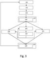
- Step 101 is repeated after step 143, after which the method continues as shown in Fig. 3 .
- step 121 has been omitted and a step 151 has been added.
- the control information received in step 105 describes the function corresponding to the user interaction.
- both steps 121 and 151 are present.
- Step 151 comprises controlling a further lighting device of the one or more lighting devices based on the received control information.
- step 151 is performed at least partly in parallel with step 107.
- step 151 is performed before or after step 107.
- the function may not only be described using audio and/or video information, but also demonstrated on a nearby "test" light, where the test light could be chosen such that it has minimal impact on the overall light level/ ambience. For example, if a room has five lights, the system could assign one light as "test" light, such that every interaction with a physical control of a light control device will only impact that specific light.
- step 121 has been omitted and step 107 comprise a sub step 161.
- the control information received in step 105 describes the function corresponding to the user interaction.
- both steps 121 and 161 are present.
- Step 161 comprises displaying an animation demonstrating the function. More specifically, step 161 comprises displaying a virtual room comprising a virtual representation of the at least one lighting device and the animation superimposed over the virtual room.
- a virtual representation of a light or set of lights may be used do display the description of the function.
- the Echo Show could display a virtual room where the light would behave as being controlled by this light control device.
- a similar approach can be used with an augmented reality-capable device.
- Fig. 6 depicts a block diagram illustrating an exemplary data processing system that may perform the method as described with reference to Figs. 2 to 5 .
- the data processing system 300 may include at least one processor 302 coupled to memory elements 304 through a system bus 306. As such, the data processing system may store program code within memory elements 304. Further, the processor 302 may execute the program code accessed from the memory elements 304 via a system bus 306. In one aspect, the data processing system may be implemented as a computer that is suitable for storing and/or executing program code. It should be appreciated, however, that the data processing system 300 may be implemented in the form of any system including a processor and a memory that is capable of performing the functions described within this specification.
- the memory elements 304 may include one or more physical memory devices such as, for example, local memory 308 and one or more bulk storage devices 310.
- the local memory may refer to random access memory or other non-persistent memory device(s) generally used during actual execution of the program code.
- a bulk storage device may be implemented as a hard drive or other persistent data storage device.
- the processing system 300 may also include one or more cache memories (not shown) that provide temporary storage of at least some program code in order to reduce the quantity of times program code must be retrieved from the bulk storage device 310 during execution.
- the processing system 300 may also be able to use memory elements of another processing system, e.g. if the processing system 300 is part of a cloud-computing platform.
- I/O devices depicted as an input device 312 and an output device 314 optionally can be coupled to the data processing system.
- input devices may include, but are not limited to, a keyboard, a pointing device such as a mouse, a microphone (e.g. for voice and/or speech recognition), or the like.
- output devices may include, but are not limited to, a monitor or a display, speakers, or the like. Input and/or output devices may be coupled to the data processing system either directly or through intervening I/O controllers.
- the input and the output devices may be implemented as a combined input/output device (illustrated in Fig. 6 with a dashed line surrounding the input device 312 and the output device 314).
- a combined device is a touch sensitive display, also sometimes referred to as a "touch screen display” or simply "touch screen”.
- input to the device may be provided by a movement of a physical object, such as e.g. a stylus or a finger of a user, on or near the touch screen display.
- a network adapter 316 may also be coupled to the data processing system to enable it to become coupled to other systems, computer systems, remote network devices, and/or remote storage devices through intervening private or public networks.
- the network adapter may comprise a data receiver for receiving data that is transmitted by said systems, devices and/or networks to the data processing system 300, and a data transmitter for transmitting data from the data processing system 300 to said systems, devices and/or networks.
- Modems, cable modems, and Ethernet cards are examples of different types of network adapter that may be used with the data processing system 300.
- the memory elements 304 may store an application 318.
- the application 318 may be stored in the local memory 308, the one or more bulk storage devices 310, or separate from the local memory and the bulk storage devices.
- the data processing system 300 may further execute an operating system (not shown in Fig. 6 ) that can facilitate execution of the application 318.
- the application 318 being implemented in the form of executable program code, can be executed by the data processing system 300, e.g., by the processor 302. Responsive to executing the application, the data processing system 300 may be configured to perform one or more operations or method steps described herein.
- Fig. 6 shows the input device 312 and the output device 314 as being separate from the network adapter 316.
- input may be received via the network adapter 316 and output be transmitted via the network adapter 316.
- the data processing system 300 may be a cloud server.
- the input may be received from and the output may be transmitted to a user device that acts as a terminal.
- Various embodiments of the invention may be implemented as a program product for use with a computer system, where the program(s) of the program product define functions of the embodiments (including the methods described herein).
- the program(s) can be contained on a variety of non-transitory computer-readable storage media, where, as used herein, the expression "non-transitory computer readable storage media" comprises all computer-readable media, with the sole exception being a transitory, propagating signal.
- the program(s) can be contained on a variety of transitory computer-readable storage media.
- Illustrative computer-readable storage media include, but are not limited to: (i) non-writable storage media (e.g., read-only memory devices within a computer such as CD-ROM disks readable by a CD-ROM drive, ROM chips or any type of solid-state non-volatile semiconductor memory) on which information is permanently stored; and (ii) writable storage media (e.g., flash memory, floppy disks within a diskette drive or hard-disk drive or any type of solid-state random-access semiconductor memory) on which alterable information is stored.
- the computer program may be run on the processor 302 described herein.
Landscapes
- Engineering & Computer Science (AREA)
- Computer Networks & Wireless Communication (AREA)
- Physics & Mathematics (AREA)
- General Physics & Mathematics (AREA)
- Circuit Arrangement For Electric Light Sources In General (AREA)
Claims (15)
- System (1) zum Steuern eines Beleuchtungssystems (11), wobei das Beleuchtungssystem (11) eine Lichtsteuerungsvorrichtung (21-23) und eine Beleuchtungsvorrichtung (31-35) umfasst, wobei die Lichtsteuerungsvorrichtung (21-23) zum Steuern der Beleuchtungsvorrichtung (31-35) verwendet wird, wobei das System (1) Folgendes umfasst:mindestens eine Eingabeschnittstelle (3);mindestens eine Ausgabeschnittstelle (4); undmindestens einen Prozessor (5), der konfiguriert ist zum:- Empfangen, über die mindestens eine Eingabeschnittstelle (3), einer Benutzereingabe, die eine Anforderung darstellt, einen Abfragemodus zu aktivieren, in dem der Benutzer die Lichtsteuerungsvorrichtung verwenden kann, um Informationen über diese Lichtsteuerungsvorrichtung zu erhalten, ohne die Beleuchtungsvorrichtung zu steuern, die dieser Lichtsteuerungsvorrichtung zugeordnet ist,- Übertragen, über die mindestens eine Ausgabeschnittstelle (4), eines Befehls an das Beleuchtungssystem (11), wobei der Befehl das Beleuchtungssystem (11) anweist, die Steuerung der Beleuchtungsvorrichtung (31-35) durch die Lichtsteuerungsvorrichtung (21-23) vorübergehend zu deaktivieren,- Empfangen, über die mindestens eine Eingabeschnittstelle (3), von Steuerungsinformationen von dem Beleuchtungssystem (11), wobei die Steuerungsinformationen eine Benutzerinteraktion mit der Lichtsteuerungsvorrichtung (21-23) beschreiben;- Empfangen, über die mindestens eine Eingabeschnittstelle (3), weiterer Steuerungsinformationen von dem Beleuchtungssystem (11), wobei die weiteren Steuerungsinformationen eine Funktion beschreiben, die der Benutzerinteraktion entspricht,- Rendern, über die mindestens eine Ausgabeschnittstelle (4), von Audio- und/oder visuellen Informationen, welche die Funktion beschreiben, die der Benutzerinteraktion an den Benutzer entspricht, und- Übertragen, über die mindestens eine Ausgabeschnittstelle (4), eines weiteren Befehls an das Beleuchtungssystem (11), wobei der weitere Befehl das Beleuchtungssystem (11) anweist, die Steuerung der Beleuchtungsvorrichtung (31-35) durch die Lichtsteuerungsvorrichtung (21-23) zu aktivieren.
- System (1) nach Anspruch 1, wobei der Befehl und der weitere Befehl an die Lichtsteuerungsvorrichtung (21-23) übertragen werden und die Steuerungsinformationen und die weiteren Steuerungsinformationen von der Lichtsteuerungsvorrichtung (21-23) empfangen werden.
- System (1) nach Anspruch 1 oder 2, wobei die Steuerungsinformationen eine Kennung der Lichtsteuerungsvorrichtung (21-23) umfassen und eine Benutzerinteraktion mit der Lichtsteuerungsvorrichtung (21-23) beschreiben, und der mindestens eine Prozessor (5) konfiguriert ist, um eine Beschreibung der Funktion aus der Kennung und der Beschreibung der Benutzerinteraktion zu bestimmen.
- System (1) nach Anspruch 1 oder 2, wobei die Steuerungsinformationen eine Benutzerinteraktion mit einem Knopf oder Drehschalter der Lichtsteuerungsvorrichtung (21-23) beschreiben und die weiteren Steuerungsinformationen eine Funktion beschreiben, die der Benutzerinteraktion mit dem Knopf oder dem Drehschalter der Lichtsteuerungsvorrichtung (21-23) entspricht.
- System (1) nach Anspruch 1 oder 2, wobei der mindestens eine Prozessor (5) konfiguriert ist, um über eine Anzeige (9) und/oder einen Lautsprecher einer mobilen Vorrichtung (1) und/oder einen Sprachassistenten Audio- und/oder visuelle Informationen zu rendern, welche die Funktion beschreiben.
- System (1) nach Anspruch 1 oder 2, wobei das Beleuchtungssystem (11) eine Vielzahl von Lichtsteuerungsvorrichtungen (21-23) umfasst und der mindestens eine Prozessor (5) konfiguriert ist zum:- Bestimmen einer Teilmenge der Vielzahl von Lichtsteuerungsvorrichtungen (21-23), wobei die Teilmenge von Lichtsteuervorrichtungen (21-23) die Lichtsteuerungsvorrichtung (21-23) umfasst und verwendet wird, um einen Satz von Beleuchtungsvorrichtungen (31-35) zu steuern, wobei der Satz von Beleuchtungsvorrichtungen (31-35) die Beleuchtungsvorrichtung (31-35) umfasst,- Übertragen, über die mindestens eine Ausgabeschnittstelle (4), eines oder mehrerer Befehle an das Beleuchtungssystem (11), wobei der eine oder die mehreren Befehle das Beleuchtungssystem (11) anweisen, die Steuerung des Satzes von Beleuchtungsvorrichtungen (31-35) vorübergehend durch die Teilmenge von Lichtsteuerungsvorrichtungen (21-23) zu deaktivieren, und- Übertragen, über die mindestens eine Ausgabeschnittstelle (4), eines oder mehrerer weiterer Befehle an das Beleuchtungssystem (11), wobei der eine oder die mehreren weiteren Befehle das Beleuchtungssystem (11) anweisen, die Steuerung des Satzes von Beleuchtungsvorrichtungen (31-35) durch die Teilmenge von Lichtsteuerungsvorrichtungen (21-23) zu aktivieren.
- Steuerungssystem (1) nach Anspruch 6, wobei der mindestens eine Prozessor (5) konfiguriert ist, um die Teilmenge der Vielzahl von Lichtsteuerungsvorrichtungen (21-23) basierend auf der Benutzereingabe zu bestimmen.
- System (1) nach Anspruch 6, wobei der mindestens eine Prozessor (5) konfiguriert ist, um einen Standort des Benutzers zu bestimmen und die Teilmenge der Vielzahl von Lichtsteuerungsvorrichtungen (21-23) basierend auf dem Standort zu bestimmen.
- System (1) nach Anspruch 1 oder 2, wobei der mindestens eine Prozessor (5) konfiguriert ist, um über die mindestens eine Eingabeschnittstelle (3) eine weitere Benutzereingabe zu empfangen, die eine Anforderung darstellt, den Abfragemodus zu deaktivieren und über die mindestens eine Ausgabeschnittstelle (4) den weiteren Befehl beim Empfangen der weiteren Benutzereingabe zu übertragen.
- System (1) nach Anspruch 1 oder 2, wobei der mindestens eine Prozessor (5) konfiguriert ist, um einen Zeitnehmer beim Empfangen der Benutzereingabe zu starten und über die mindestens eine Ausgabeschnittstelle (4) den weiteren Befehl nach Ablauf des Zeitnehmers zu übertragen.
- System (1) nach Anspruch 6, wobei der mindestens eine Prozessor (5) konfiguriert ist, um über die mindestens eine Ausgabeschnittstelle (4) eine weitere Beleuchtungsvorrichtung (31- 35) der einen oder mehreren Beleuchtungsvorrichtungen (31-35) basierend auf den empfangenen Steuerungsinformationen zu steuern.
- System (1) nach Anspruch 1 oder 2, wobei der mindestens eine Prozessor (5) konfiguriert ist, um über die mindestens eine Ausgabeschnittstelle (4) eine die Funktion darstellende Animation anzuzeigen.
- System (1) nach Anspruch 12, wobei der mindestens eine Prozessor (5) konfiguriert ist, um über die mindestens eine Ausgabeschnittstelle (4) einen virtuellen Raum anzuzeigen, der eine virtuelle Darstellung der mindestens einen Beleuchtungsvorrichtung (31-35) und der dem virtuellen Raum überlagerten Animation umfasst.
- Verfahren zum Steuern eines Beleuchtungssystems, wobei das Beleuchtungssystem eine Lichtsteuerungsvorrichtung und eine Beleuchtungsvorrichtung umfasst, wobei die Lichtsteuerungsvorrichtung zum Steuern der Beleuchtungsvorrichtung verwendet wird, wobei das Verfahren Folgendes umfasst:- Empfangen (101) einer Benutzereingabe, die eine Anforderung darstellt, einen Abfragemodus zu aktivieren, in dem der Benutzer die Lichtsteuerungsvorrichtung verwenden kann, um Informationen über diese Lichtsteuerungsvorrichtung zu erhalten, ohne die Beleuchtungsvorrichtung zu steuern, die dieser Lichtsteuerungsvorrichtung zugeordnet ist;- Übertragen (103) eines Befehls an das Beleuchtungssystem, wobei der Befehl das Beleuchtungssystem anweist, die Steuerung der mindestens einen Beleuchtungsvorrichtung durch die Lichtsteuerungsvorrichtung vorübergehend zu deaktivieren;- Empfangen von Steuerungsinformationen von dem Beleuchtungssystem, wobei die Steuerungsinformationen eine Benutzerinteraktion mit der Lichtsteuerungsvorrichtung beschreiben;- Empfangen (105) weiterer Steuerungsinformationen von dem Beleuchtungssystem, wobei die weiteren Steuerungsinformationen eine Funktion beschreiben, die der Benutzerinteraktion entspricht;- Rendern (107) von Audio- und/oder visuellen Informationen, welche die Funktion beschreiben, die der Benutzerinteraktion an den Benutzer entspricht; und- Übertragen (109) eines weiteren Befehls an das Beleuchtungssystem, wobei der weitere Befehl das Beleuchtungssystem anweist, die Steuerung der Beleuchtungsvorrichtung durch die Lichtsteuerungsvorrichtung zu aktivieren.
- Computerprogramm oder eine Folge von Computerprogrammen, umfassend mindestens einen Softwarecodeabschnitt oder ein computerlesbares Computerprogrammprodukt, auf dem der mindestens eine Softwarecodeabschnitt gespeichert ist, wobei der Softwarecodeabschnitt Anweisungen umfasst, die, wenn der Softwarecodeabschnitt durch ein Rechnersystem ausgeführt wird, das Rechnersystem veranlassen, das Verfahren nach Anspruch 14 durchzuführen, wobei das Rechnersystem mindestens eine Eingabeschnittstelle, mindestens eine Ausgabeschnittstelle und mindestens einen Prozessor umfasst; und wobei die Benutzereingabe, die eine Anforderung zum Aktivieren eines Abfragemodus darstellt, über die mindestens eine Eingabeschnittstelle empfangen wird, wobei der Befehl an das Beleuchtungssystem über die mindestens eine Ausgabeschnittstelle übertragen wird, wobei die Steuerungsinformationen und die weiteren Steuerungsinformationen über die mindestens eine Eingabeschnittstelle von dem Beleuchtungssystem empfangen werden, wobei die Audio- und/oder visuellen Informationen über die mindestens eine Ausgabeschnittstelle gerendert werden; und wobei der weitere Befehl über die mindestens eine Ausgabeschnittstelle an das Beleuchtungssystem übertragen wird.
Applications Claiming Priority (2)
| Application Number | Priority Date | Filing Date | Title |
|---|---|---|---|
| EP20150318 | 2020-01-06 | ||
| PCT/EP2020/086308 WO2021139975A1 (en) | 2020-01-06 | 2020-12-15 | Disable control of a lighting device by a light control device in a query mode |
Publications (2)
| Publication Number | Publication Date |
|---|---|
| EP4088552A1 EP4088552A1 (de) | 2022-11-16 |
| EP4088552B1 true EP4088552B1 (de) | 2023-08-23 |
Family
ID=69137776
Family Applications (1)
| Application Number | Title | Priority Date | Filing Date |
|---|---|---|---|
| EP20821306.6A Active EP4088552B1 (de) | 2020-01-06 | 2020-12-15 | Deaktivierung der steuerung einer beleuchtungsvorrichtung durch eine lichtsteuerungsvorrichtung in einem abfragemodus |
Country Status (6)
| Country | Link |
|---|---|
| US (1) | US12213230B2 (de) |
| EP (1) | EP4088552B1 (de) |
| JP (1) | JP7194871B1 (de) |
| CN (1) | CN114868460B (de) |
| ES (1) | ES2961586T3 (de) |
| WO (1) | WO2021139975A1 (de) |
Families Citing this family (4)
| Publication number | Priority date | Publication date | Assignee | Title |
|---|---|---|---|---|
| US20230239989A1 (en) * | 2020-10-13 | 2023-07-27 | G&G Led, Llc | Method and System for Changing a Function of a Lighting Device |
| US20220117062A1 (en) * | 2020-10-13 | 2022-04-14 | G&G Led, Llc | Method and System for Changing a Function of a Lighting Device |
| CN116762480A (zh) * | 2021-01-25 | 2023-09-15 | 昕诺飞控股有限公司 | 基于音频和/或视频信号源的标识符选择照明设备集合 |
| CN118511651A (zh) * | 2022-01-04 | 2024-08-16 | 昕诺飞控股有限公司 | 从音乐视频中提取调色板以生成光效果 |
Family Cites Families (12)
| Publication number | Priority date | Publication date | Assignee | Title |
|---|---|---|---|---|
| DE10062669A1 (de) | 2000-12-15 | 2002-06-20 | Bsh Bosch Siemens Hausgeraete | Eingabevorrichtung und Verfahren zur Eingabe von Informationen in eine Steuereinheit |
| KR20110118693A (ko) * | 2009-01-29 | 2011-10-31 | 코닌클리케 필립스 일렉트로닉스 엔.브이. | 주변 조명 조건들에 반응하는 조명 제어 시스템 |
| US10649418B2 (en) * | 2013-12-11 | 2020-05-12 | Ademco Inc. | Building automation controller with configurable audio/visual cues |
| US9699836B2 (en) * | 2014-06-18 | 2017-07-04 | Farhad Bahrehmand | Multifunctional universal LED driver |
| US10356882B2 (en) * | 2014-08-29 | 2019-07-16 | At&T Intellectual Property I, L.P. | Methods, systems, and products for control of electrical loads |
| CN107079569B (zh) * | 2014-11-24 | 2019-10-11 | 飞利浦灯具控股公司 | 控制网络连接照明设备 |
| US10057966B2 (en) * | 2016-04-05 | 2018-08-21 | Ilumisys, Inc. | Connected lighting system |
| WO2017194358A1 (en) * | 2016-05-10 | 2017-11-16 | Philips Lighting Holding B.V. | Use of a lighting system to indicate application status. |
| WO2018007450A1 (en) | 2016-07-08 | 2018-01-11 | Philips Lighting Holding B.V. | Programming rules for controlling lighting |
| US9854653B1 (en) * | 2017-01-31 | 2017-12-26 | Crestron Electronics Inc. | Scalable building control system, method, and apparatus |
| US11602034B2 (en) * | 2017-05-08 | 2023-03-07 | Signify Holding B.V. | Forming groups of devices by analyzing device control information |
| US10448484B1 (en) * | 2018-10-10 | 2019-10-15 | Abl Ip Holding Llc | Integrated digital lighting controller |
-
2020
- 2020-12-15 CN CN202080092000.2A patent/CN114868460B/zh active Active
- 2020-12-15 JP JP2022541609A patent/JP7194871B1/ja active Active
- 2020-12-15 US US17/790,563 patent/US12213230B2/en active Active
- 2020-12-15 ES ES20821306T patent/ES2961586T3/es active Active
- 2020-12-15 EP EP20821306.6A patent/EP4088552B1/de active Active
- 2020-12-15 WO PCT/EP2020/086308 patent/WO2021139975A1/en not_active Ceased
Also Published As
| Publication number | Publication date |
|---|---|
| US20230092759A1 (en) | 2023-03-23 |
| JP2023500748A (ja) | 2023-01-10 |
| ES2961586T3 (es) | 2024-03-12 |
| WO2021139975A1 (en) | 2021-07-15 |
| CN114868460A (zh) | 2022-08-05 |
| EP4088552A1 (de) | 2022-11-16 |
| US12213230B2 (en) | 2025-01-28 |
| JP7194871B1 (ja) | 2022-12-22 |
| CN114868460B (zh) | 2025-08-19 |
Similar Documents
| Publication | Publication Date | Title |
|---|---|---|
| EP4088552B1 (de) | Deaktivierung der steuerung einer beleuchtungsvorrichtung durch eine lichtsteuerungsvorrichtung in einem abfragemodus | |
| CN109379261B (zh) | 智能设备的控制方法、装置、系统、设备和存储介质 | |
| US9999116B2 (en) | Tablet-based commissioning tool for addressable lighting | |
| RU2658501C2 (ru) | Способ и прибор для идентификации типа электронного устройства, подключенного к интеллектуальной розетке | |
| US10869292B2 (en) | Conditionally providing location-based functions | |
| EP4490983B1 (de) | Steuerung von beleuchtungsvorrichtungen als gruppe, wenn in einem anderen raumbereich eine lichtszene oder ein modus aktiviert wird | |
| US20230371152A1 (en) | Controlling a controllable device in dependence on hand shape and or hand size and/or manner of holding and/or touching a control device | |
| CN113940143B (zh) | 用于协助用户配置照明系统的系统及方法 | |
| US12495480B2 (en) | Displaying a light control UI on a device upon detecting interaction with a light control device | |
| WO2021160552A1 (en) | Associating another control action with a physical control if an entertainment mode is active | |
| EP4272518B1 (de) | Aufforderung an eine beleuchtungsvorrichtung, andere beleuchtungsvorrichtungen zu steuern, um lichteffekte von einem lichtskript wiederzugeben | |
| US11871498B2 (en) | Determining a reachability of an electronic device over multiple wireless communication protocols | |
| WO2025146299A1 (en) | Lighting control ui for controlling a physical lighting device and a virtual lighting device |
Legal Events
| Date | Code | Title | Description |
|---|---|---|---|
| STAA | Information on the status of an ep patent application or granted ep patent |
Free format text: STATUS: UNKNOWN |
|
| STAA | Information on the status of an ep patent application or granted ep patent |
Free format text: STATUS: THE INTERNATIONAL PUBLICATION HAS BEEN MADE |
|
| PUAI | Public reference made under article 153(3) epc to a published international application that has entered the european phase |
Free format text: ORIGINAL CODE: 0009012 |
|
| STAA | Information on the status of an ep patent application or granted ep patent |
Free format text: STATUS: REQUEST FOR EXAMINATION WAS MADE |
|
| 17P | Request for examination filed |
Effective date: 20220808 |
|
| AK | Designated contracting states |
Kind code of ref document: A1 Designated state(s): AL AT BE BG CH CY CZ DE DK EE ES FI FR GB GR HR HU IE IS IT LI LT LU LV MC MK MT NL NO PL PT RO RS SE SI SK SM TR |
|
| GRAP | Despatch of communication of intention to grant a patent |
Free format text: ORIGINAL CODE: EPIDOSNIGR1 |
|
| STAA | Information on the status of an ep patent application or granted ep patent |
Free format text: STATUS: GRANT OF PATENT IS INTENDED |
|
| DAV | Request for validation of the european patent (deleted) | ||
| DAX | Request for extension of the european patent (deleted) | ||
| INTG | Intention to grant announced |
Effective date: 20230324 |
|
| P01 | Opt-out of the competence of the unified patent court (upc) registered |
Effective date: 20230530 |
|
| GRAS | Grant fee paid |
Free format text: ORIGINAL CODE: EPIDOSNIGR3 |
|
| GRAA | (expected) grant |
Free format text: ORIGINAL CODE: 0009210 |
|
| STAA | Information on the status of an ep patent application or granted ep patent |
Free format text: STATUS: THE PATENT HAS BEEN GRANTED |
|
| AK | Designated contracting states |
Kind code of ref document: B1 Designated state(s): AL AT BE BG CH CY CZ DE DK EE ES FI FR GB GR HR HU IE IS IT LI LT LU LV MC MK MT NL NO PL PT RO RS SE SI SK SM TR |
|
| REG | Reference to a national code |
Ref country code: GB Ref legal event code: FG4D |
|
| REG | Reference to a national code |
Ref country code: CH Ref legal event code: EP |
|
| REG | Reference to a national code |
Ref country code: DE Ref legal event code: R096 Ref document number: 602020016394 Country of ref document: DE |
|
| REG | Reference to a national code |
Ref country code: IE Ref legal event code: FG4D |
|
| REG | Reference to a national code |
Ref country code: SE Ref legal event code: TRGR |
|
| REG | Reference to a national code |
Ref country code: LT Ref legal event code: MG9D |
|
| REG | Reference to a national code |
Ref country code: NL Ref legal event code: MP Effective date: 20230823 |
|
| REG | Reference to a national code |
Ref country code: AT Ref legal event code: MK05 Ref document number: 1604084 Country of ref document: AT Kind code of ref document: T Effective date: 20230823 |
|
| PG25 | Lapsed in a contracting state [announced via postgrant information from national office to epo] |
Ref country code: GR Free format text: LAPSE BECAUSE OF FAILURE TO SUBMIT A TRANSLATION OF THE DESCRIPTION OR TO PAY THE FEE WITHIN THE PRESCRIBED TIME-LIMIT Effective date: 20231124 |
|
| PG25 | Lapsed in a contracting state [announced via postgrant information from national office to epo] |
Ref country code: IS Free format text: LAPSE BECAUSE OF FAILURE TO SUBMIT A TRANSLATION OF THE DESCRIPTION OR TO PAY THE FEE WITHIN THE PRESCRIBED TIME-LIMIT Effective date: 20231223 |
|
| PG25 | Lapsed in a contracting state [announced via postgrant information from national office to epo] |
Ref country code: RS Free format text: LAPSE BECAUSE OF FAILURE TO SUBMIT A TRANSLATION OF THE DESCRIPTION OR TO PAY THE FEE WITHIN THE PRESCRIBED TIME-LIMIT Effective date: 20230823 Ref country code: PT Free format text: LAPSE BECAUSE OF FAILURE TO SUBMIT A TRANSLATION OF THE DESCRIPTION OR TO PAY THE FEE WITHIN THE PRESCRIBED TIME-LIMIT Effective date: 20231226 Ref country code: NO Free format text: LAPSE BECAUSE OF FAILURE TO SUBMIT A TRANSLATION OF THE DESCRIPTION OR TO PAY THE FEE WITHIN THE PRESCRIBED TIME-LIMIT Effective date: 20231123 Ref country code: NL Free format text: LAPSE BECAUSE OF FAILURE TO SUBMIT A TRANSLATION OF THE DESCRIPTION OR TO PAY THE FEE WITHIN THE PRESCRIBED TIME-LIMIT Effective date: 20230823 Ref country code: LV Free format text: LAPSE BECAUSE OF FAILURE TO SUBMIT A TRANSLATION OF THE DESCRIPTION OR TO PAY THE FEE WITHIN THE PRESCRIBED TIME-LIMIT Effective date: 20230823 Ref country code: LT Free format text: LAPSE BECAUSE OF FAILURE TO SUBMIT A TRANSLATION OF THE DESCRIPTION OR TO PAY THE FEE WITHIN THE PRESCRIBED TIME-LIMIT Effective date: 20230823 Ref country code: IS Free format text: LAPSE BECAUSE OF FAILURE TO SUBMIT A TRANSLATION OF THE DESCRIPTION OR TO PAY THE FEE WITHIN THE PRESCRIBED TIME-LIMIT Effective date: 20231223 Ref country code: HR Free format text: LAPSE BECAUSE OF FAILURE TO SUBMIT A TRANSLATION OF THE DESCRIPTION OR TO PAY THE FEE WITHIN THE PRESCRIBED TIME-LIMIT Effective date: 20230823 Ref country code: GR Free format text: LAPSE BECAUSE OF FAILURE TO SUBMIT A TRANSLATION OF THE DESCRIPTION OR TO PAY THE FEE WITHIN THE PRESCRIBED TIME-LIMIT Effective date: 20231124 Ref country code: FI Free format text: LAPSE BECAUSE OF FAILURE TO SUBMIT A TRANSLATION OF THE DESCRIPTION OR TO PAY THE FEE WITHIN THE PRESCRIBED TIME-LIMIT Effective date: 20230823 Ref country code: AT Free format text: LAPSE BECAUSE OF FAILURE TO SUBMIT A TRANSLATION OF THE DESCRIPTION OR TO PAY THE FEE WITHIN THE PRESCRIBED TIME-LIMIT Effective date: 20230823 |
|
| PG25 | Lapsed in a contracting state [announced via postgrant information from national office to epo] |
Ref country code: PL Free format text: LAPSE BECAUSE OF FAILURE TO SUBMIT A TRANSLATION OF THE DESCRIPTION OR TO PAY THE FEE WITHIN THE PRESCRIBED TIME-LIMIT Effective date: 20230823 |
|
| REG | Reference to a national code |
Ref country code: ES Ref legal event code: FG2A Ref document number: 2961586 Country of ref document: ES Kind code of ref document: T3 Effective date: 20240312 |
|
| PG25 | Lapsed in a contracting state [announced via postgrant information from national office to epo] |
Ref country code: SM Free format text: LAPSE BECAUSE OF FAILURE TO SUBMIT A TRANSLATION OF THE DESCRIPTION OR TO PAY THE FEE WITHIN THE PRESCRIBED TIME-LIMIT Effective date: 20230823 Ref country code: RO Free format text: LAPSE BECAUSE OF FAILURE TO SUBMIT A TRANSLATION OF THE DESCRIPTION OR TO PAY THE FEE WITHIN THE PRESCRIBED TIME-LIMIT Effective date: 20230823 Ref country code: EE Free format text: LAPSE BECAUSE OF FAILURE TO SUBMIT A TRANSLATION OF THE DESCRIPTION OR TO PAY THE FEE WITHIN THE PRESCRIBED TIME-LIMIT Effective date: 20230823 Ref country code: DK Free format text: LAPSE BECAUSE OF FAILURE TO SUBMIT A TRANSLATION OF THE DESCRIPTION OR TO PAY THE FEE WITHIN THE PRESCRIBED TIME-LIMIT Effective date: 20230823 Ref country code: CZ Free format text: LAPSE BECAUSE OF FAILURE TO SUBMIT A TRANSLATION OF THE DESCRIPTION OR TO PAY THE FEE WITHIN THE PRESCRIBED TIME-LIMIT Effective date: 20230823 Ref country code: SK Free format text: LAPSE BECAUSE OF FAILURE TO SUBMIT A TRANSLATION OF THE DESCRIPTION OR TO PAY THE FEE WITHIN THE PRESCRIBED TIME-LIMIT Effective date: 20230823 |
|
| REG | Reference to a national code |
Ref country code: DE Ref legal event code: R097 Ref document number: 602020016394 Country of ref document: DE |
|
| PLBE | No opposition filed within time limit |
Free format text: ORIGINAL CODE: 0009261 |
|
| STAA | Information on the status of an ep patent application or granted ep patent |
Free format text: STATUS: NO OPPOSITION FILED WITHIN TIME LIMIT |
|
| 26N | No opposition filed |
Effective date: 20240524 |
|
| PG25 | Lapsed in a contracting state [announced via postgrant information from national office to epo] |
Ref country code: SI Free format text: LAPSE BECAUSE OF FAILURE TO SUBMIT A TRANSLATION OF THE DESCRIPTION OR TO PAY THE FEE WITHIN THE PRESCRIBED TIME-LIMIT Effective date: 20230823 |
|
| REG | Reference to a national code |
Ref country code: CH Ref legal event code: PL |
|
| PG25 | Lapsed in a contracting state [announced via postgrant information from national office to epo] |
Ref country code: LU Free format text: LAPSE BECAUSE OF NON-PAYMENT OF DUE FEES Effective date: 20231215 |
|
| PG25 | Lapsed in a contracting state [announced via postgrant information from national office to epo] |
Ref country code: MC Free format text: LAPSE BECAUSE OF FAILURE TO SUBMIT A TRANSLATION OF THE DESCRIPTION OR TO PAY THE FEE WITHIN THE PRESCRIBED TIME-LIMIT Effective date: 20230823 |
|
| REG | Reference to a national code |
Ref country code: BE Ref legal event code: MM Effective date: 20231231 |
|
| PG25 | Lapsed in a contracting state [announced via postgrant information from national office to epo] |
Ref country code: MC Free format text: LAPSE BECAUSE OF FAILURE TO SUBMIT A TRANSLATION OF THE DESCRIPTION OR TO PAY THE FEE WITHIN THE PRESCRIBED TIME-LIMIT Effective date: 20230823 Ref country code: LU Free format text: LAPSE BECAUSE OF NON-PAYMENT OF DUE FEES Effective date: 20231215 |
|
| REG | Reference to a national code |
Ref country code: IE Ref legal event code: MM4A |
|
| PG25 | Lapsed in a contracting state [announced via postgrant information from national office to epo] |
Ref country code: IE Free format text: LAPSE BECAUSE OF NON-PAYMENT OF DUE FEES Effective date: 20231215 |
|
| PG25 | Lapsed in a contracting state [announced via postgrant information from national office to epo] |
Ref country code: BE Free format text: LAPSE BECAUSE OF NON-PAYMENT OF DUE FEES Effective date: 20231231 |
|
| PG25 | Lapsed in a contracting state [announced via postgrant information from national office to epo] |
Ref country code: CH Free format text: LAPSE BECAUSE OF NON-PAYMENT OF DUE FEES Effective date: 20231231 |
|
| PG25 | Lapsed in a contracting state [announced via postgrant information from national office to epo] |
Ref country code: IE Free format text: LAPSE BECAUSE OF NON-PAYMENT OF DUE FEES Effective date: 20231215 Ref country code: CH Free format text: LAPSE BECAUSE OF NON-PAYMENT OF DUE FEES Effective date: 20231231 Ref country code: BE Free format text: LAPSE BECAUSE OF NON-PAYMENT OF DUE FEES Effective date: 20231231 |
|
| PG25 | Lapsed in a contracting state [announced via postgrant information from national office to epo] |
Ref country code: BG Free format text: LAPSE BECAUSE OF FAILURE TO SUBMIT A TRANSLATION OF THE DESCRIPTION OR TO PAY THE FEE WITHIN THE PRESCRIBED TIME-LIMIT Effective date: 20230823 |
|
| PG25 | Lapsed in a contracting state [announced via postgrant information from national office to epo] |
Ref country code: BG Free format text: LAPSE BECAUSE OF FAILURE TO SUBMIT A TRANSLATION OF THE DESCRIPTION OR TO PAY THE FEE WITHIN THE PRESCRIBED TIME-LIMIT Effective date: 20230823 |
|
| PG25 | Lapsed in a contracting state [announced via postgrant information from national office to epo] |
Ref country code: CY Free format text: LAPSE BECAUSE OF FAILURE TO SUBMIT A TRANSLATION OF THE DESCRIPTION OR TO PAY THE FEE WITHIN THE PRESCRIBED TIME-LIMIT; INVALID AB INITIO Effective date: 20201215 |
|
| PG25 | Lapsed in a contracting state [announced via postgrant information from national office to epo] |
Ref country code: HU Free format text: LAPSE BECAUSE OF FAILURE TO SUBMIT A TRANSLATION OF THE DESCRIPTION OR TO PAY THE FEE WITHIN THE PRESCRIBED TIME-LIMIT; INVALID AB INITIO Effective date: 20201215 |
|
| PG25 | Lapsed in a contracting state [announced via postgrant information from national office to epo] |
Ref country code: TR Free format text: LAPSE BECAUSE OF FAILURE TO SUBMIT A TRANSLATION OF THE DESCRIPTION OR TO PAY THE FEE WITHIN THE PRESCRIBED TIME-LIMIT Effective date: 20230823 |
|
| PGFP | Annual fee paid to national office [announced via postgrant information from national office to epo] |
Ref country code: GB Payment date: 20251223 Year of fee payment: 6 |
|
| PGFP | Annual fee paid to national office [announced via postgrant information from national office to epo] |
Ref country code: IT Payment date: 20251218 Year of fee payment: 6 |
|
| PGFP | Annual fee paid to national office [announced via postgrant information from national office to epo] |
Ref country code: FR Payment date: 20251230 Year of fee payment: 6 |
|
| PGFP | Annual fee paid to national office [announced via postgrant information from national office to epo] |
Ref country code: SE Payment date: 20251222 Year of fee payment: 6 |
|
| PGFP | Annual fee paid to national office [announced via postgrant information from national office to epo] |
Ref country code: ES Payment date: 20260122 Year of fee payment: 6 |
|
| PGFP | Annual fee paid to national office [announced via postgrant information from national office to epo] |
Ref country code: DE Payment date: 20260220 Year of fee payment: 6 |