EP4088455B1 - Verfahren und vorrichtung zum videodecodieren mittels palettenmodus - Google Patents
Verfahren und vorrichtung zum videodecodieren mittels palettenmodus Download PDFInfo
- Publication number
- EP4088455B1 EP4088455B1 EP21738316.5A EP21738316A EP4088455B1 EP 4088455 B1 EP4088455 B1 EP 4088455B1 EP 21738316 A EP21738316 A EP 21738316A EP 4088455 B1 EP4088455 B1 EP 4088455B1
- Authority
- EP
- European Patent Office
- Prior art keywords
- palette
- video
- coding
- block
- chroma
- Prior art date
- Legal status (The legal status is an assumption and is not a legal conclusion. Google has not performed a legal analysis and makes no representation as to the accuracy of the status listed.)
- Active
Links
Images


Classifications
-
- H—ELECTRICITY
- H04—ELECTRIC COMMUNICATION TECHNIQUE
- H04N—PICTORIAL COMMUNICATION, e.g. TELEVISION
- H04N19/00—Methods or arrangements for coding, decoding, compressing or decompressing digital video signals
- H04N19/10—Methods or arrangements for coding, decoding, compressing or decompressing digital video signals using adaptive coding
- H04N19/102—Methods or arrangements for coding, decoding, compressing or decompressing digital video signals using adaptive coding characterised by the element, parameter or selection affected or controlled by the adaptive coding
- H04N19/103—Selection of coding mode or of prediction mode
- H04N19/105—Selection of the reference unit for prediction within a chosen coding or prediction mode, e.g. adaptive choice of position and number of pixels used for prediction
-
- H—ELECTRICITY
- H04—ELECTRIC COMMUNICATION TECHNIQUE
- H04N—PICTORIAL COMMUNICATION, e.g. TELEVISION
- H04N19/00—Methods or arrangements for coding, decoding, compressing or decompressing digital video signals
- H04N19/10—Methods or arrangements for coding, decoding, compressing or decompressing digital video signals using adaptive coding
- H04N19/134—Methods or arrangements for coding, decoding, compressing or decompressing digital video signals using adaptive coding characterised by the element, parameter or criterion affecting or controlling the adaptive coding
- H04N19/157—Assigned coding mode, i.e. the coding mode being predefined or preselected to be further used for selection of another element or parameter
-
- H—ELECTRICITY
- H04—ELECTRIC COMMUNICATION TECHNIQUE
- H04N—PICTORIAL COMMUNICATION, e.g. TELEVISION
- H04N19/00—Methods or arrangements for coding, decoding, compressing or decompressing digital video signals
- H04N19/10—Methods or arrangements for coding, decoding, compressing or decompressing digital video signals using adaptive coding
- H04N19/169—Methods or arrangements for coding, decoding, compressing or decompressing digital video signals using adaptive coding characterised by the coding unit, i.e. the structural portion or semantic portion of the video signal being the object or the subject of the adaptive coding
- H04N19/17—Methods or arrangements for coding, decoding, compressing or decompressing digital video signals using adaptive coding characterised by the coding unit, i.e. the structural portion or semantic portion of the video signal being the object or the subject of the adaptive coding the unit being an image region, e.g. an object
- H04N19/176—Methods or arrangements for coding, decoding, compressing or decompressing digital video signals using adaptive coding characterised by the coding unit, i.e. the structural portion or semantic portion of the video signal being the object or the subject of the adaptive coding the unit being an image region, e.g. an object the region being a block, e.g. a macroblock
-
- H—ELECTRICITY
- H04—ELECTRIC COMMUNICATION TECHNIQUE
- H04N—PICTORIAL COMMUNICATION, e.g. TELEVISION
- H04N19/00—Methods or arrangements for coding, decoding, compressing or decompressing digital video signals
- H04N19/10—Methods or arrangements for coding, decoding, compressing or decompressing digital video signals using adaptive coding
- H04N19/169—Methods or arrangements for coding, decoding, compressing or decompressing digital video signals using adaptive coding characterised by the coding unit, i.e. the structural portion or semantic portion of the video signal being the object or the subject of the adaptive coding
- H04N19/186—Methods or arrangements for coding, decoding, compressing or decompressing digital video signals using adaptive coding characterised by the coding unit, i.e. the structural portion or semantic portion of the video signal being the object or the subject of the adaptive coding the unit being a colour or a chrominance component
-
- H—ELECTRICITY
- H04—ELECTRIC COMMUNICATION TECHNIQUE
- H04N—PICTORIAL COMMUNICATION, e.g. TELEVISION
- H04N19/00—Methods or arrangements for coding, decoding, compressing or decompressing digital video signals
- H04N19/10—Methods or arrangements for coding, decoding, compressing or decompressing digital video signals using adaptive coding
- H04N19/169—Methods or arrangements for coding, decoding, compressing or decompressing digital video signals using adaptive coding characterised by the coding unit, i.e. the structural portion or semantic portion of the video signal being the object or the subject of the adaptive coding
- H04N19/1883—Methods or arrangements for coding, decoding, compressing or decompressing digital video signals using adaptive coding characterised by the coding unit, i.e. the structural portion or semantic portion of the video signal being the object or the subject of the adaptive coding the unit relating to sub-band structure, e.g. hierarchical level, directional tree, e.g. low-high [LH], high-low [HL], high-high [HH]
-
- H—ELECTRICITY
- H04—ELECTRIC COMMUNICATION TECHNIQUE
- H04N—PICTORIAL COMMUNICATION, e.g. TELEVISION
- H04N19/00—Methods or arrangements for coding, decoding, compressing or decompressing digital video signals
- H04N19/42—Methods or arrangements for coding, decoding, compressing or decompressing digital video signals characterised by implementation details or hardware specially adapted for video compression or decompression, e.g. dedicated software implementation
- H04N19/423—Methods or arrangements for coding, decoding, compressing or decompressing digital video signals characterised by implementation details or hardware specially adapted for video compression or decompression, e.g. dedicated software implementation characterised by memory arrangements
-
- H—ELECTRICITY
- H04—ELECTRIC COMMUNICATION TECHNIQUE
- H04N—PICTORIAL COMMUNICATION, e.g. TELEVISION
- H04N19/00—Methods or arrangements for coding, decoding, compressing or decompressing digital video signals
- H04N19/46—Embedding additional information in the video signal during the compression process
-
- H—ELECTRICITY
- H04—ELECTRIC COMMUNICATION TECHNIQUE
- H04N—PICTORIAL COMMUNICATION, e.g. TELEVISION
- H04N19/00—Methods or arrangements for coding, decoding, compressing or decompressing digital video signals
- H04N19/50—Methods or arrangements for coding, decoding, compressing or decompressing digital video signals using predictive coding
- H04N19/593—Methods or arrangements for coding, decoding, compressing or decompressing digital video signals using predictive coding involving spatial prediction techniques
-
- H—ELECTRICITY
- H04—ELECTRIC COMMUNICATION TECHNIQUE
- H04N—PICTORIAL COMMUNICATION, e.g. TELEVISION
- H04N19/00—Methods or arrangements for coding, decoding, compressing or decompressing digital video signals
- H04N19/70—Methods or arrangements for coding, decoding, compressing or decompressing digital video signals characterised by syntax aspects related to video coding, e.g. related to compression standards
-
- H—ELECTRICITY
- H04—ELECTRIC COMMUNICATION TECHNIQUE
- H04N—PICTORIAL COMMUNICATION, e.g. TELEVISION
- H04N19/00—Methods or arrangements for coding, decoding, compressing or decompressing digital video signals
- H04N19/90—Methods or arrangements for coding, decoding, compressing or decompressing digital video signals using coding techniques not provided for in groups H04N19/10-H04N19/85, e.g. fractals
- H04N19/96—Tree coding, e.g. quad-tree coding
Definitions
- the present application generally relates to video data coding and compression, and in particular using palette mode.
- Digital video is supported by a variety of electronic devices, such as digital televisions, laptop or desktop computers, tablet computers, digital cameras, digital recording devices, digital media players, video gaming consoles, smart phones, video teleconferencing devices, video streaming devices, etc.
- the electronic devices transmit, receive, encode, decode, and/or store digital video data by implementing video compression/decompression standards as defined by MPEG-4, ITU-T H.263, ITU-T H.264/MPEG-4, Part 10, Advanced Video Coding (AVC), High Efficiency Video Coding (HEVC), and Versatile Video Coding (VVC) standard.
- Video compression typically includes performing spatial (intra frame) prediction and/or temporal (inter frame) prediction to reduce or remove redundancy inherent in the video data.
- a video frame is partitioned into one or more slices, each slice having multiple video blocks, which may also be referred to as coding tree units (CTUs).
- Each CTU may contain one coding unit (CU) or recursively split into smaller CUs until the predefined minimum CU size is reached.
- Each CU also named leaf CU
- Each CU contains one or multiple transform units (TUs) and each CU also contains one or multiple prediction units (PUs).
- Each CU can be coded in either intra, inter or IBC modes.
- Video blocks in an intra coded (I) slice of a video frame are encoded using spatial prediction with respect to reference samples in neighboring blocks within the same video frame.
- Video blocks in an inter coded (P or B) slice of a video frame may use spatial prediction with respect to reference samples in neighboring blocks within the same video frame or temporal prediction with respect to reference samples in other previous and/or future reference video frames.
- the process of finding the reference block may be accomplished by block matching algorithm.
- Residual data representing pixel differences between the current block to be coded and the predictive block is referred to as a residual block or prediction errors.
- An inter-coded block is encoded according to a motion vector that points to a reference block in a reference frame forming the predictive block, and the residual block. The process of determining the motion vector is typically referred to as motion estimation.
- An intra coded block is encoded according to an intra prediction mode and the residual block.
- the residual block is transformed from the pixel domain to a transform domain, e.g., frequency domain, resulting in residual transform coefficients, which may then be quantized.
- the quantized transform coefficients initially arranged in a two-dimensional array, may be scanned to produce a one-dimensional vector of transform coefficients, and then entropy encoded into a video bitstream to achieve even more compression.
- the encoded video bitstream is then saved in a computer-readable storage medium (e.g., flash memory) to be accessed by another electronic device with digital video capability or directly transmitted to the electronic device wired or wirelessly.
- the electronic device then performs video decompression (which is an opposite process to the video compression described above) by, e.g., parsing the encoded video bitstream to obtain syntax elements from the bitstream and reconstructing the digital video data to its original format from the encoded video bitstream based at least in part on the syntax elements obtained from the bitstream, and renders the reconstructed digital video data on a display of the electronic device.
- the present invention describes implementations related to video data decoding and, more particularly, to an electronic apparatus and a method of video decoding using palette mode.
- the invention is defined in the appended claims. Enabling disclosure for the invention as defined in the claims is found in embodiments described in Table 5 and corresponding paragraphs. Any examples and embodiments of the description not falling within the scope of the claims are provided for illustrative purposes only.
- a video decoding method comprising the steps of claim 1 is proposed.
- an electronic apparatus includes one or more processing units, memory and a plurality of programs stored in the memory.
- the programs when executed by the one or more processing units, cause the electronic apparatus to perform the method as described above.
- a non-transitory computer readable storage medium stores a plurality of programs for execution by an electronic apparatus having one or more processing units.
- the programs when executed by the one or more processing units, cause the electronic apparatus to perform the method as described above.
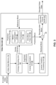
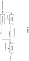
- FIG. 1 is a block diagram illustrating an exemplary system 10 for encoding and decoding video blocks in parallel in accordance with some implementations of the present disclosure.
- system 10 includes a source device 12 that generates and encodes video data to be decoded at a later time by a destination device 14.
- Source device 12 and destination device 14 may comprise any of a wide variety of electronic devices, including desktop or laptop computers, tablet computers, smart phones, set-top boxes, digital televisions, cameras, display devices, digital media players, video gaming consoles, video streaming device, or the like.
- source device 12 and destination device 14 are equipped with wireless communication capabilities.
- destination device 14 may receive the encoded video data to be decoded via a link 16.
- Link 16 may comprise any type of communication medium or device capable of moving the encoded video data from source device 12 to destination device 14.
- link 16 may comprise a communication medium to enable source device 12 to transmit the encoded video data directly to destination device 14 in real-time.
- the encoded video data may be modulated according to a communication standard, such as a wireless communication protocol, and transmitted to destination device 14.
- the communication medium may comprise any wireless or wired communication medium, such as a radio frequency (RF) spectrum or one or more physical transmission lines.
- the communication medium may form part of a packet-based network, such as a local area network, a wide-area network, or a global network such as the Internet.
- the communication medium may include routers, switches, base stations, or any other equipment that may be useful to facilitate communication from source device 12 to destination device 14.
- the encoded video data may be transmitted from output interface 22 to a storage device 32. Subsequently, the encoded video data in storage device 32 may be accessed by destination device 14 via input interface 28.
- Storage device 32 may include any of a variety of distributed or locally accessed data storage media such as a hard drive, Blu-ray discs, DVDs, CD-ROMs, flash memory, volatile or non-volatile memory, or any other suitable digital storage media for storing encoded video data.
- storage device 32 may correspond to a file server or another intermediate storage device that may hold the encoded video data generated by source device 12. Destination device 14 may access the stored video data from storage device 32 via streaming or downloading.
- the file server may be any type of computer capable of storing encoded video data and transmitting the encoded video data to destination device 14.
- Exemplary file servers include a web server (e.g., for a website), an FTP server, network attached storage (NAS) devices, or a local disk drive.
- Destination device 14 may access the encoded video data through any standard data connection, including a wireless channel (e.g., a Wi-Fi connection), a wired connection (e.g., DSL, cable modem, etc.), or a combination of both that is suitable for accessing encoded video data stored on a file server.
- the transmission of encoded video data from storage device 32 may be a streaming transmission, a download transmission, or a combination of both.
- source device 12 includes a video source 18, a video encoder 20 and an output interface 22.
- Video source 18 may include a source such as a video capture device, e.g., a video camera, a video archive containing previously captured video, a video feed interface to receive video from a video content provider, and/or a computer graphics system for generating computer graphics data as the source video, or a combination of such sources.
- a video capture device e.g., a video camera, a video archive containing previously captured video, a video feed interface to receive video from a video content provider, and/or a computer graphics system for generating computer graphics data as the source video, or a combination of such sources.
- source device 12 and destination device 14 may form camera phones or video phones.
- the implementations described in the present application may be applicable to video coding in general, and may be applied to wireless and/or wired applications.
- the captured, pre-captured, or computer-generated video may be encoded by video encoder 20.
- the encoded video data may be transmitted directly to destination device 14 via output interface 22 of source device 12.
- the encoded video data may also (or alternatively) be stored onto storage device 32 for later access by destination device 14 or other devices, for decoding and/or playback.
- Output interface 22 may further include a modem and/or a transmitter.
- Destination device 14 includes an input interface 28, a video decoder 30, and a display device 34.
- Input interface 28 may include a receiver and/or a modem and receive the encoded video data over link 16.
- the encoded video data communicated over link 16, or provided on storage device 32 may include a variety of syntax elements generated by video encoder 20 for use by video decoder 30 in decoding the video data. Such syntax elements may be included within the encoded video data transmitted on a communication medium, stored on a storage medium, or stored a file server.
- destination device 14 may include a display device 34, which can be an integrated display device and an external display device that is configured to communicate with destination device 14.
- Display device 34 displays the decoded video data to a user, and may comprise any of a variety of display devices such as a liquid crystal display (LCD), a plasma display, an organic light emitting diode (OLED) display, or another type of display device.
- LCD liquid crystal display
- OLED organic light emitting diode
- Video encoder 20 and video decoder 30 may operate according to proprietary or industry standards, such as VVC, HEVC, MPEG-4, Part 10, Advanced Video Coding (AVC), or extensions of such standards. It should be understood that the present application is not limited to a specific video coding/decoding standard and may be applicable to other video coding/decoding standards. It is generally contemplated that video encoder 20 of source device 12 may be configured to encode video data according to any of these current or future standards. Similarly, it is also generally contemplated that video decoder 30 of destination device 14 may be configured to decode video data according to any of these current or future standards.
- Video encoder 20 and video decoder 30 each may be implemented as any of a variety of suitable encoder circuitry, such as one or more microprocessors, digital signal processors (DSPs), application specific integrated circuits (ASICs), field programmable gate arrays (FPGAs), discrete logic, software, hardware, firmware or any combinations thereof.
- DSPs digital signal processors
- ASICs application specific integrated circuits
- FPGAs field programmable gate arrays
- an electronic device may store instructions for the software in a suitable, non-transitory computer-readable medium and execute the instructions in hardware using one or more processors to perform the video coding/decoding operations disclosed in the present disclosure.
- Each of video encoder 20 and video decoder 30 may be included in one or more encoders or decoders, either of which may be integrated as part of a combined encoder/decoder (CODEC) in a respective device.
- CDEC combined encoder/decoder
- FIG. 2 is a block diagram illustrating an exemplary video encoder 20 in accordance with some implementations described in the present application.
- Video encoder 20 may perform intra and inter predictive coding of video blocks within video frames. Intra predictive coding relies on spatial prediction to reduce or remove spatial redundancy in video data within a given video frame or picture. Inter predictive coding relies on temporal prediction to reduce or remove temporal redundancy in video data within adjacent video frames or pictures of a video sequence.
- Motion compensation performed by motion compensation unit 44, may involve fetching or generating the predictive block based on the motion vector determined by motion estimation unit 42.
- motion compensation unit 44 may locate a predictive block to which the motion vector points in one of the reference frame lists, retrieve the predictive block from DPB 64, and forward the predictive block to summer 50.
- Summer 50 then forms a residual video block of pixel difference values by subtracting pixel values of the predictive block provided by motion compensation unit 44 from the pixel values of the current video block being coded.
- the pixel difference values forming the residual vide block may include luma or chroma difference components or both.
- Motion compensation unit 44 may also generate syntax elements associated with the video blocks of a video frame for use by video decoder 30 in decoding the video blocks of the video frame.
- the syntax elements may include, for example, syntax elements defining the motion vector used to identify the predictive block, any flags indicating the prediction mode, or any other syntax information described herein. Note that motion estimation unit 42 and motion compensation unit 44 may be highly integrated, but are illustrated separately for conceptual purposes.
- intra BC unit 48 may use motion estimation unit 42 and motion compensation unit 44, in whole or in part, to perform such functions for Intra BC prediction according to the implementations described herein.
- a predictive block may be a block that is deemed as closely matching the block to be coded, in terms of pixel difference, which may be determined by sum of absolute difference (SAD), sum of squared difference (SSD), or other difference metrics, and identification of the predictive block may include calculation of values for sub-integer pixel positions.
- Intra prediction processing unit 46 may intra-predict a current video block, as an alternative to the inter-prediction performed by motion estimation unit 42 and motion compensation unit 44, or the intra block copy prediction performed by intra BC unit 48, as described above.
- intra prediction processing unit 46 may determine an intra prediction mode to use to encode a current block. To do so, intra prediction processing unit 46 may encode a current block using various intra prediction modes, e.g., during separate encoding passes, and intra prediction processing unit 46 (or a mode select unit, in some examples) may select an appropriate intra prediction mode to use from the tested intra prediction modes.
- Intra prediction processing unit 46 may provide information indicative of the selected intra-prediction mode for the block to entropy encoding unit 56. Entropy encoding unit 56 may encode the information indicating the selected intra-prediction mode in the bitstream.
- Transform processing unit 52 may send the resulting transform coefficients to quantization unit 54.
- Quantization unit 54 quantizes the transform coefficients to further reduce bit rate. The quantization process may also reduce the bit depth associated with some or all of the coefficients. The degree of quantization may be modified by adjusting a quantization parameter.
- quantization unit 54 may then perform a scan of a matrix including the quantized transform coefficients.
- entropy encoding unit 56 may perform the scan.
- FIG. 3 is a block diagram illustrating an exemplary video decoder 30 in accordance with some implementations of the present application.
- Video decoder 30 includes video data memory 79, entropy decoding unit 80, prediction processing unit 81, inverse quantization unit 86, inverse transform processing unit 88, summer 90, and DPB 92.
- Prediction processing unit 81 further includes motion compensation unit 82, intra prediction processing unit 84, and intra BC unit 85.
- Video decoder 30 may perform a decoding process generally reciprocal to the encoding process described above with respect to video encoder 20 in connection with FIG. 2 .
- motion compensation unit 82 may generate prediction data based on motion vectors received from entropy decoding unit 80
- intra-prediction unit 84 may generate prediction data based on intra-prediction mode indicators received from entropy decoding unit 80.
- a unit of video decoder 30 may be tasked to perform the implementations of the present application. Also, in some examples, the implementations of the present disclosure may be divided among one or more of the units of video decoder 30.
- intra BC unit 85 may perform the implementations of the present application, alone, or in combination with other units of video decoder 30, such as motion compensation unit 82, intra prediction processing unit 84, and entropy decoding unit 80.
- video decoder 30 may not include intra BC unit 85 and the functionality of intra BC unit 85 may be performed by other components of prediction processing unit 81, such as motion compensation unit 82.
- Video data memory 79 may store video data, such as an encoded video bitstream, to be decoded by the other components of video decoder 30.
- the video data stored in video data memory 79 may be obtained, for example, from storage device 32, from a local video source, such as a camera, via wired or wireless network communication of video data, or by accessing physical data storage media (e.g., a flash drive or hard disk).
- Video data memory 79 may include a coded picture buffer (CPB) that stores encoded video data from an encoded video bitstream.
- Decoded picture buffer (DPB) 92 of video decoder 30 stores reference video data for use in decoding video data by video decoder 30 (e.g., in intra or inter predictive coding modes).
- Video data memory 79 and DPB 92 may be formed by any of a variety of memory devices, such as dynamic random access memory (DRAM), including synchronous DRAM (SDRAM), magneto-resistive RAM (MRAM), resistive RAM (RRAM), or other types of memory devices.
- DRAM dynamic random access memory
- SDRAM synchronous DRAM
- MRAM magneto-resistive RAM
- RRAM resistive RAM
- video data memory 79 and DPB 92 are depicted as two distinct components of video decoder 30 in FIG. 3 . But it will be apparent to one skilled in the art that video data memory 79 and DPB 92 may be provided by the same memory device or separate memory devices. In some examples, video data memory 79 may be on-chip with other components of video decoder 30, or off-chip relative to those components.
- video decoder 30 receives an encoded video bitstream that represents video blocks of an encoded video frame and associated syntax elements.
- Video decoder 30 may receive the syntax elements at the video frame level and/or the video block level.
- Entropy decoding unit 80 of video decoder 30 entropy decodes the bitstream to generate quantized coefficients, motion vectors or intra-prediction mode indicators, and other syntax elements. Entropy decoding unit 80 then forwards the motion vectors and other syntax elements to prediction processing unit 81.
- intra prediction processing unit 84 of prediction processing unit 81 may generate prediction data for a video block of the current video frame based on a signaled intra prediction mode and reference data from previously decoded blocks of the current frame.
- motion compensation unit 82 of prediction processing unit 81 produces one or more predictive blocks for a video block of the current video frame based on the motion vectors and other syntax elements received from entropy decoding unit 80.
- Each of the predictive blocks may be produced from a reference frame within one of the reference frame lists.
- Video decoder 30 may construct the reference frame lists, List 0 and List 1, using default construction techniques based on reference frames stored in DPB 92.
- intra BC unit 85 of prediction processing unit 81 produces predictive blocks for the current video block based on block vectors and other syntax elements received from entropy decoding unit 80.
- the predictive blocks may be within a reconstructed region of the same picture as the current video block defined by video encoder 20.
- Motion compensation unit 82 and/or intra BC unit 85 determines prediction information for a video block of the current video frame by parsing the motion vectors and other syntax elements, and then uses the prediction information to produce the predictive blocks for the current video block being decoded. For example, motion compensation unit 82 uses some of the received syntax elements to determine a prediction mode (e.g., intra or inter prediction) used to code video blocks of the video frame, an inter prediction frame type (e.g., B or P), construction information for one or more of the reference frame lists for the frame, motion vectors for each inter predictive encoded video block of the frame, inter prediction status for each inter predictive coded video block of the frame, and other information to decode the video blocks in the current video frame.
- a prediction mode e.g., intra or inter prediction
- an inter prediction frame type e.g., B or P
- intra BC unit 85 may use some of the received syntax elements, e.g., a flag, to determine that the current video block was predicted using the intra BC mode, construction information of which video blocks of the frame are within the reconstructed region and should be stored in DPB 92, block vectors for each intra BC predicted video block of the frame, intra BC prediction status for each intra BC predicted video block of the frame, and other information to decode the video blocks in the current video frame.
- a flag e.g., a flag
- Motion compensation unit 82 may also perform interpolation using the interpolation filters as used by video encoder 20 during encoding of the video blocks to calculate interpolated values for sub-integer pixels of reference blocks. In this case, motion compensation unit 82 may determine the interpolation filters used by video encoder 20 from the received syntax elements and use the interpolation filters to produce predictive blocks.
- Inverse quantization unit 86 inverse quantizes the quantized transform coefficients provided in the bitstream and entropy decoded by entropy decoding unit 80 using the same quantization parameter calculated by video encoder 20 for each video block in the video frame to determine a degree of quantization.
- Inverse transform processing unit 88 applies an inverse transform, e.g., an inverse DCT, an inverse integer transform, or a conceptually similar inverse transform process, to the transform coefficients in order to reconstruct the residual blocks in the pixel domain.
- summer 90 reconstructs decoded video block for the current video block by summing the residual block from inverse transform processing unit 88 and a corresponding predictive block generated by motion compensation unit 82 and intra BC unit 85.
- An in-loop filter (not pictured) may be positioned between summer 90 and DPB 92 to further process the decoded video block.
- the decoded video blocks in a given frame are then stored in DPB 92, which stores reference frames used for subsequent motion compensation of next video blocks.
- DPB 92 or a memory device separate from DPB 92, may also store decoded video for later presentation on a display device, such as display device 34 of FIG. 1 .
- a video sequence typically includes an ordered set of frames or pictures.
- Each frame may include three sample arrays, denoted SL, SCb, and SCr.
- SL is a two-dimensional array of luma samples.
- SCb is a two-dimensional array of Cb chroma samples.
- SCr is a two-dimensional array of Cr chroma samples.
- a frame may be monochrome and therefore includes only one two-dimensional array of luma samples.
- video encoder 20 (or more specifically partition unit 45) generates an encoded representation of a frame by first partitioning the frame into a set of coding tree units (CTUs).
- a video frame may include an integer number of CTUs ordered consecutively in a raster scan order from left to right and from top to bottom.
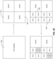
- Each CTU is a largest logical coding unit and the width and height of the CTU are signaled by the video encoder 20 in a sequence parameter set, such that all the CTUs in a video sequence have the same size being one of 128 ⁇ 128, 64 ⁇ 64, 32 ⁇ 32, and 16 ⁇ 16. But it should be noted that the present application is not necessarily limited to a particular size. As shown in FIG.
- each CTU may comprise one coding tree block (CTB) of luma samples, two corresponding coding tree blocks of chroma samples, and syntax elements used to code the samples of the coding tree blocks.
- the syntax elements describe properties of different types of units of a coded block of pixels and how the video sequence can be reconstructed at the video decoder 30, including inter or intra prediction, intra prediction mode, motion vectors, and other parameters.
- a CTU may comprise a single coding tree block and syntax elements used to code the samples of the coding tree block.
- a coding tree block may be an NxN block of samples.
- video encoder 20 may recursively perform tree partitioning such as binary-tree partitioning, ternary-tree partitioning, quad-tree partitioning or a combination of both on the coding tree blocks of the CTU and divide the CTU into smaller coding units (CUs).
- tree partitioning such as binary-tree partitioning, ternary-tree partitioning, quad-tree partitioning or a combination of both on the coding tree blocks of the CTU and divide the CTU into smaller coding units (CUs).
- the 64x64 CTU 400 is first divided into four smaller CU, each having a block size of 32x32.
- CU 410 and CU 420 are each divided into four CUs of 16x16 by block size.
- the two 16x16 CUs 430 and 440 are each further divided into four CUs of 8x8 by block size.
- each leaf node of the quad-tree corresponding to one CU of a respective size ranging from 32x32 to 8x8.
- each CU may comprise a coding block (CB) of luma samples and two corresponding coding blocks of chroma samples of a frame of the same size, and syntax elements used to code the samples of the coding blocks.
- CB coding block
- a CU may comprise a single coding block and syntax structures used to code the samples of the coding block.
- quad-tree partitioning depicted in FIGS. 4C and 4D is only for illustrative purposes and one CTU can be split into CUs to adapt to varying local characteristics based on quad/ternary/binary-tree partitions.
- one CTU is partitioned by a quad-tree structure and each quad-tree leaf CU can be further partitioned by a binary and ternary tree structure.
- FIG. 4E there are five partitioning types, i.e., quaternary partitioning, horizontal binary partitioning, vertical binary partitioning, horizontal ternary partitioning, and vertical ternary partitioning.
- video encoder 20 may further partition a coding block of a CU into one or more MxN prediction blocks (PB).
- a prediction block is a rectangular (square or non-square) block of samples on which the same prediction, inter or intra, is applied.
- a prediction unit (PU) of a CU may comprise a prediction block of luma samples, two corresponding prediction blocks of chroma samples, and syntax elements used to predict the prediction blocks.
- a PU may comprise a single prediction block and syntax structures used to predict the prediction block.
- Video encoder 20 may generate predictive luma, Cb, and Cr blocks for luma, Cb, and Cr prediction blocks of each PU of the CU.
- Video encoder 20 may use intra prediction or inter prediction to generate the predictive blocks for a PU. If video encoder 20 uses intra prediction to generate the predictive blocks of a PU, video encoder 20 may generate the predictive blocks of the PU based on decoded samples of the frame associated with the PU. If video encoder 20 uses inter prediction to generate the predictive blocks of a PU, video encoder 20 may generate the predictive blocks of the PU based on decoded samples of one or more frames other than the frame associated with the PU.
- video encoder 20 may generate a luma residual block for the CU by subtracting the CU's predictive luma blocks from its original luma coding block such that each sample in the CU's luma residual block indicates a difference between a luma sample in one of the CU's predictive luma blocks and a corresponding sample in the CU's original luma coding block.
- video encoder 20 may generate a Cb residual block and a Cr residual block for the CU, respectively, such that each sample in the CU's Cb residual block indicates a difference between a Cb sample in one of the CU's predictive Cb blocks and a corresponding sample in the CU's original Cb coding block and each sample in the CU's Cr residual block may indicate a difference between a Cr sample in one of the CU's predictive Cr blocks and a corresponding sample in the CU's original Cr coding block.
- video encoder 20 may use quad-tree partitioning to decompose the luma, Cb, and Cr residual blocks of a CU into one or more luma, Cb, and Cr transform blocks.
- a transform block is a rectangular (square or non-square) block of samples on which the same transform is applied.
- a transform unit (TU) of a CU may comprise a transform block of luma samples, two corresponding transform blocks of chroma samples, and syntax elements used to transform the transform block samples.
- each TU of a CU may be associated with a luma transform block, a Cb transform block, and a Cr transform block.
- the luma transform block associated with the TU may be a sub-block of the CU's luma residual block.
- the Cb transform block may be a sub-block of the CU's Cb residual block.
- the Cr transform block may be a sub-block of the CU's Cr residual block.
- a TU may comprise a single transform block and syntax structures used to transform the samples of the transform block.
- Video encoder 20 may apply one or more transforms to a luma transform block of a TU to generate a luma coefficient block for the TU.
- a coefficient block may be a two-dimensional array of transform coefficients.
- a transform coefficient may be a scalar quantity.
- Video encoder 20 may apply one or more transforms to a Cb transform block of a TU to generate a Cb coefficient block for the TU.
- Video encoder 20 may apply one or more transforms to a Cr transform block of a TU to generate a Cr coefficient block for the TU.
- video encoder 20 may quantize the coefficient block. Quantization generally refers to a process in which transform coefficients are quantized to possibly reduce the amount of data used to represent the transform coefficients, providing further compression.
- video encoder 20 may entropy encode syntax elements indicating the quantized transform coefficients. For example, video encoder 20 may perform Context-Adaptive Binary Arithmetic Coding (CABAC) on the syntax elements indicating the quantized transform coefficients.
- CABAC Context-Adaptive Binary Arithmetic Coding
- video encoder 20 may output a bitstream that includes a sequence of bits that forms a representation of coded frames and associated data, which is either saved in storage device 32 or transmitted to destination device 14.
- video decoder 30 may parse the bitstream to obtain syntax elements from the bitstream.
- Video decoder 30 may reconstruct the frames of the video data based at least in part on the syntax elements obtained from the bitstream.
- the process of reconstructing the video data is generally reciprocal to the encoding process performed by video encoder 20.
- video decoder 30 may perform inverse transforms on the coefficient blocks associated with TUs of a current CU to reconstruct residual blocks associated with the TUs of the current CU.
- Video decoder 30 also reconstructs the coding blocks of the current CU by adding the samples of the predictive blocks for PUs of the current CU to corresponding samples of the transform blocks of the TUs of the current CU. After reconstructing the coding blocks for each CU of a frame, video decoder 30 may reconstruct the frame.
- palette-based coding is another coding scheme that has been adopted by many video coding standards.
- a video coder e.g., video encoder 20 or video decoder 30
- the palette table includes the most dominant (e.g., frequently used) pixel values in the given block. Pixel values that are not frequently represented in the video data of the given block are either not included in the palette table or included in the palette table as escape colors.
- Each entry in the palette table includes an index for a corresponding pixel value that in the palette table.
- the palette indices for samples in the block may be coded to indicate which entry from the palette table is to be used to predict or reconstruct which sample.
- This palette mode starts with the process of generating a palette predictor for a first block of a picture, slice, tile, or other such grouping of video blocks.
- the palette predictor for subsequent video blocks is typically generated by updating a previously used palette predictor.
- the palette predictor is defined at a picture level. In other words, a picture may include multiple coding blocks, each having its own palette table, but there is one palette predictor for the entire picture.
- a video decoder may utilize a palette predictor for determining new palette entries in the palette table used for reconstructing a video block.
- the palette predictor may include palette entries from a previously used palette table or even be initialized with a most recently used palette table by including all entries of the most recently used palette table.
- the palette predictor may include fewer than all the entries from the most recently used palette table and then incorporate some entries from other previously used palette tables.
- the palette predictor may have the same size as the palette tables used for coding different blocks or may be larger or smaller than the palette tables used for coding different blocks.
- the palette predictor is implemented as a first-in-first-out (FIFO) table including 64 palette entries.
- a video decoder may receive, from the encoded video bitstream, a one-bit flag for each entry of the palette predictor.
- the one-bit flag may have a first value (e.g., a binary one) indicating that the associated entry of the palette predictor is to be included in the palette table or a second value (e.g., a binary zero) indicating that the associated entry of the palette predictor is not to be included in the palette table. If the size of palette predictor is larger than the palette table used for a block of video data, then the video decoder may stop receiving more flags once a maximum size for the palette table is reached.
- some entries in a palette table may be directly signaled in the encoded video bitstream instead of being determined using the palette predictor.
- the video decoder may receive, from the encoded video bitstream, three separate m-bit values indicating the pixel values for the luma and two chroma components associated with the entry, where m represents the bit depth of the video data.
- those palette entries derived from the palette predictor only require a one-bit flag. Therefore, signaling some or all palette entries using the palette predictor can significantly reduce the number of bits needed to signal the entries of a new palette table, thereby improving the overall coding efficiency of palette mode coding.
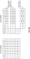
- FIGS. 5A through 5B are block diagrams illustrating examples of using palette tables for coding video data in accordance with some implementations of the present disclosure.
- palette colors are defined by a palette table and encoded by the palette table coding syntax (e.g., palette_predictor_run, num_signaled_palette_entries, new_palette_entries).
- An escape flag, palette_escape_val_present_flag, is signaled for each CU to indicate if escape symbols are present in the current CU. If escape symbols are present, the palette table is augmented by one more entry and the last index is assigned to the escape mode.
- Palette indices of all pixels in a CU form a palette index map and are encoded by the palette index map coding syntax (e.g., num_palette_indices_minus1, palette_idx_idc, copy_above_indices_for_final_run_flag, palette_transpose_flag, copy_above_palette_indices_flag, palette_run_prefix, palette_run_suffix).
- An example of palette mode coded CU is illustrated in Figure 5A in which the palette size is 4.
- the first 3 samples in the CU use palette entries 2, 0, and 3, respectively, for reconstruction.
- the "x" sample in the CU represents an escape symbol.
- a CU level flag, palette_escape_val_present_flag, indicates whether any escape symbols are present in the CU. If escape symbols are present, the palette size is augmented by one and the last index is used to indicate the escape symbol. Thus, in Figure 5A , index 4 is assigned to the escape symbol.
- a palette index (e.g., index 4 in FIG. 5A ) corresponds to the escape symbol, additional overhead are signaled to indicate the corresponding colors of the sample.
- a modified k-means clustering algorithm is used for the derivation of the palette for lossy coding.
- the first sample of the block is added to the palette.
- the sum of absolute difference (SAD) between the sample and each of the current palette color is calculated. If the distortion for each of the components is less than a threshold value for the palette entry corresponding to the minimum SAD, the sample is added to the cluster belonging to the palette entry. Otherwise, the sample is added as a new palette entry.
- a centroid for that cluster is updated and becomes the palette entry of that cluster.
- the clusters are sorted in a descending order of usage.
- the palette entry corresponding to each entry is updated.
- the cluster centroid is used as the palette entry.
- a rate-distortion analysis is performed to analyze whether any entry from the palette predictor may be more suitable to be used as the updated palette entry instead of the centroid when the cost of coding the palette entries is taken into account. This process is continued till all the clusters are processed or the maximum palette size is reached.
- the sample is converted to an escape symbol. Additionally, duplicate palette entries are removed and their clusters are merged.
- each sample in the block is assigned the index of the nearest (in SAD) palette entry. Then, the samples are assigned to 'INDEX' or 'COPY_ABOVE' mode. For each sample for which either 'INDEX' or 'COPY_ABOVE' mode is possible, the run for each mode is determined. Then, the cost of coding the mode is calculated. The mode for which the cost is lower is selected.
- a palette predictor For coding of the palette table, a palette predictor is maintained. The maximum size of the palette and the maximum size of the palette predictor can both signaled in the SPS (or other coding levels such as PPS, slice header, etc.).
- the palette predictor is initialized at the beginning of each slice where the palette predictor is reset to 0.
- a reuse flag is signaled to indicate whether it is part of the current palette. As shown in Figure 5B , the reuse flags, palette_predictor_run, are sent. After this, the number of new palette entries are signaled using exponential Golomb code of order 0 through the syntax num_signaled_palette_entries.
- new_palette_entries[] are signaled.
- the palette predictor is updated using the current palette, and entries from the previous palette predictor which are not reused in the current palette will be added at the end of new palette predictor until the maximum size allowed is reached.
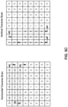
- the indices are coded using horizontal or vertical traverse scans as shown in Figure 5C .
- the scan order is explicitly signaled in the bitstream using the palette_transpose_flag.
- the palette indices are coded using two main palette sample modes: 'INDEX' and 'COPY_ABOVE'.
- 'INDEX' mode the palette index is explicitly signaled.
- 'COPY_ABOVE' mode the palette index of the sample in the row above is copied.
- a run value is signaled which specifies the number pixels that are coded using the same mode. The mode is signaled using a flag except for the top row when horizontal scan is used or the first column when the vertical scan is used, or when the previous mode was 'COPY_ABOVE'.
- the coding order for index map is as follows: First, the number of index values for the CU is signaled using the syntax num_palette_indices_minus1, which is followed by signalling of the actual index values for the entire CU using the syntax palette_idx_idc. Both the number of indices as well as the index values are coded in bypass mode. This groups the index-related bypass-coded bins together. Then the palette mode (INDEX or COPY_ABOVE) and run are signaled in an interleaved manner using the syntax copy_above_palette_indices_flag, palette_run_prefix and palette_run_suffix.
- copy_above_palette _indices_flag is a context coded flag (only one bin), the codewords of palette_run_prefix is determined through the process described in Table 3 below and the first 5 bins are context coded. palette_run_suffix is coded as bypass bin. Finally, the component escape values corresponding to the escape samples for the entire CU are grouped together and coded in the bypass mode.
- An additional syntax element, copy_above_indices_for_final_run_flag, is signaled after signalling the index values. This syntax element, in conjunction with the number of indices, eliminates the need to signal the run value corresponding to the last run in the block.
- VTM VVC
- dual tree is enabled for I-slice which separate the coding unit partitioning for luma and chroma components.
- palette is applied on luma (Y component) and chroma (Cb and Cr components) separately. If dual tree is disabled, palette will be applied on Y, Cb, Cr components jointly.
- the array indices xC, yC specify the location ( xC, yC ) of the sample relative to the top-left luma sample of the picture.
- the array index startComp specifies the first color component of the current palette table.
- startComp 0 indicates the Y component;
- startComp equal to 1 indicates the Cb component;
- startComp equal to 2 indicates the Cr component.
- numComps specifies the number of color components in the current palette table.
- the palette predictor consists of palette entries from previous coding units that are used to predict the entries in the current palette.
- the variable PredictorPaletteSize[ startComp ] specifies the size of the palette predictor for the first color component of the current palette table startComp.
- PalettePredictorEntryReuseFlags[ i ] 1 specifies that the i-th entry in the palette predictor is reused in the current palette.
- PalettePredictorEntryReuseFlags[ i ] 0 specifies that the i-th entry in the palette predictor is not an entry in the current palette. All elements of the array PalettePredictorEntryReuseFlags[ i ] are initialized to 0.
- palette_predictor _run is used to determine the number of zeros that precede a non-zero entry in the array PalettePredictorEntryReuseFlags.
- palette_predictor_run shall be in the range of 0 to ( PredictorPaletteSize - predictorEntryIdx ), inclusive, where predictorEntryIdx corresponds to the current position in the array PalettePredictorEntryReuseFlags.
- the variable NumPredictedPaletteEntries specifies the number of entries in the current palette that are reused from the predictor palette.
- the value of NumPredictedPaletteEntries shall be in the range of 0 to palette_max_size, inclusive.
- num_signaled_palette_entries specifies the number of entries in the current palette that are explicitly signaled for the first color component of the current palette table startComp.
- the variable PredictorPaletteEntries[ cIdx ][ i ] specifies the i-th element in the predictor palette for the color component cIdx.
- escape _val_present_ flag 0 specifies that there are no escape coded samples in the current coding unit. When not present, the value of palette_escape_val_present_flag is inferred to be equal to 1.
- the variable MaxPaletteIndex specifies the maximum possible value for a palette index for the current coding unit. The value of MaxPaletteIndex is set equal to CurrentPaletteSize[ startComp ] - 1 + palette_escape_val_present_flag.
- num_palette_indices_minus1 plus 1 is the number of palette indices explicitly signaled or inferred for the current block. When num_palette_indices_minus1 is not present, it is inferred to be equal to 0.
- palette_idx_idc is an indication of an index to the palette table, CurrentPaletteEntries.
- the value of palette_idx_idc shall be in the range of 0 to MaxPaletteIndex, inclusive, for the first index in the block and in the range of 0 to ( MaxPaletteIndex - 1 ), inclusive, for the remaining indices in the block.
- palette_idx_idc is not present, it is inferred to be equal to 0.
- the variable PaletteIndexIdc[ i ] stores the i-th palette_idx_idc explicitly signaled or inferred. All elements of the array PaletteIndexIdc[ i ] are initialized to 0.
- copy_above_indices_for_final_run_flag 1 specifies that the palette indices of the last positions in the coding unit are copied from the palette indices in the row above if horizontal traverse scan is used or the palette indices in the left column if vertical traverse scan is used.
- copy_above_indices_for_final_run_flag 0 specifies that the palette indices of the last positions in the coding unit are copied from PaletteIndexIdc[ num_palette_indices_minus1 ]. When copy_above_indices_for_final_run_flag is not present, it is inferred to be equal to 0.
- palette_transpose_flag 1 specifies that vertical traverse scan is applied for scanning the indices for samples in the current coding unit.
- palette_transpose_flag 0 specifies that horizontal traverse scan is applied for scanning the indices for samples in the current coding unit.
- the value of palette_transpose_flag is inferred to be equal to 0.
- the array TraverseScanOrder specifies the scan order array for palette coding. TraverseScanOrder is assigned the horizontal scan order HorTravScanOrder if palette_transpose_flag is equal to 0 and TraverseScanOrder is assigned the vertical scan order VerTravScanOrder if if palette_transpose_flag is equal to 1.
- copy_above_palette_indices_flag 1 specifies that the palette index is equal to the palette index at the same location in the row above if horizontal traverse scan is used or the same location in the left column if vertical traverse scan is used.
- copy_above_palette_indices_flag 0 specifies that an indication of the palette index of the sample is coded in the bitstream or inferred.
- the variable CopyAboveIndicesFlag[ xC ][ yC ] 1 specifies that the palette index is copied from the palette index in the row above (horizontal scan) or left column (vertical scan).
- CopyAboveIndicesFlag[ xC ][ yC ] 0 specifies that the palette index is explicitly coded in the bitstream or inferred.
- the array indices xC, yC specify the location (xC, yC ) of the sample relative to the top-left luma sample of the picture.
- the value of PaletteIndexMap[ xC ][ yC ] shall be in the range of 0 to ( MaxPaletteIndex - 1), inclusive.
- the variable PaletteIndexMap[ xC ][ yC ] specifies a palette index, which is an index to the array represented by CurrentPaletteEntries.
- the array indices xC, yC specify the location (xC, yC ) of the sample relative to the top-left luma sample of the picture.
- the value of PaletteIndexMap[ xC ][ yC ] shall be in the range of 0 to MaxPaletteIndex, inclusive.
- PaletteRunMinus1 specifies the number of consecutive locations minus 1 with the same palette index as used in the corresponding position in the row above. - Otherwise, PaletteRunMinus1 specifies the number of consecutive locations minus 1 with the same palette index as used in the corresponding position in the left column.
- PaletteMaxRunMinus1 represents the maximum possible value for PaletteRunMinus1 and it is a requirement of bitstream conformance that the value of PaletteMaxRunMinus1 shall be greater than or equal to 0.
- palette_escape_val specifies the quantized escape coded sample value for a component.
- the variable PaletteEscapeVal[ cIdx ][ xC ][ yC ] specifies the escape value of a sample for which PaletteIndexMap[ xC ][ yC ] is equal to MaxPaletteIndex and palette_escape_val_present_flag is equal to 1.
- the array index cIdx specifies the color component.
- the array indices xC, yC specify the location ( xC, yC ) of the sample relative to the top-left luma sample of the picture.
- PaletteEscapeVal[ cIdx ][ xC ][ yC ] shall be in the range of 0 to (1 ⁇ ( BitDepth Y + 1 ) ) - 1, inclusive, for cIdx equal to 0, and in the range of 0 to (1 ⁇ ( BitDepthe + 1 ) ) - 1, inclusive, for cIdx not equal to 0.
- CG coefficient group
- a CU is divided into multiple line-based coefficient group, each consists of m samples, where index runs, palette index values, and quantized colors for escape mode are encoded/parsed sequentially for each CG.
- pixels in a line-based CG can be reconstructed after parsing the syntax elements, e.g., index runs, palette index values, and escape quantized colors for the CG, which highly reduce the buffer requirement in the palette mode in VTM6.0, where the syntax elements for the whole CU have to be parsed (and stored) before reconstruction
- one context coded bin copy_above_palette_indices_flag is signaled indicating the run type, i.e., INDEX or COPY_ABOVE, of the pixel.
- the decoder does not have to parse run type if the sample is in the first row (horizontal traverse scan) or in the first column (vertical traverse scan) since the INDEX mode is used by default. Nor does the decoder have to parse run type if the previously parsed run type is COPY_ABOVE.
- the index values (for INDEX mode) and quantized escape colors are coded as bypass bins and grouped apart from encoding/parsing of context coded bins to improve throughput within each line-based CG. Since the index value is now coded/parsed after run coding, encoder does not have to signal the number of index values num_palette_indices_minus1 and the last run type copy_above_indices_for_final_run_flag.
- Table 4 The syntax of the CG palette mode is illustrated in Table 4.
- FIG. 6 is a flowchart 600 illustrating an exemplary process by which a video decoder (e.g., video decoder 30) implements the techniques of decoding video data in accordance with some implementations of the present disclosure.
- a video decoder e.g., video decoder 30
- palette mode can apply for CU that are equal or smaller than 64x64 pixels.
- a minimum palette mode block size is proposed to reduce the complexity such that the palette mode is disabled for coding units whose size is smaller than the minimum palette mode block size. For example, it is proposed to disable the palette mode for all the blocks with a size smaller than a certain threshold, e.g. 16 samples. Because there are different chroma formats (e.g., 4:4:4, 4:2:2, 4:2:0) and different coding tree types (e.g., SINGLE_TREE, DUAL_TREE_LUMA and DUAL_TREE_CHROMA), this threshold may vary.
- SINGLE_TREE indicates that the luma and chroma components of an image are partitioned in the same way such that these two components share the same palette table and palette predictor under the palette mode.
- DUAL_TREE indicates that the luma and chroma components of an image are partitioned separately such that these two components have different palette tables and palette predictors under the palette mode.
- the palette mode for the chroma component of the CU that are smaller to 16 samples should be disabled to reduce the complexity.
- the following table 5 gives one example of the the proposed syntax.
- Table 5 Palette Mode Enable Flag Under Different Coding Tree Types and Chroma formats coding_unit( x0, y0, cbWidth, cbHeight, cqtDepth, treeType, modeType ) ⁇ Descriptor ...
- pred_mode_plt_flag specifies whether the palette mode is enabled (e.g., a value of 1) or disabled (e.g., a value of 0) for the coding unit.
- Parameters like SubWidthC and SubHeightC are assocaited with the chroma format of the coding unit as follows: Chroma format SubWidthC SubHeightC Monochrome 1 1 4:4:4 1 1 4:2:2 2 1 4:2:0 2 2 2
- monochrome sampling there is only one sample array, which is nominally considered the luma array. In 4:2:0 sampling, each of the two chroma arrays has half the height and half the width of the luma array.
- each of the two chroma arrays has the same height and half the width of the luma array.
- each of the two chroma arrays has the same height and width as the luma array.
- the palette mode is disabled for small-size block depending on the luma block size.
- the palette mode for CU that are smaller to 16 pixels depended on luma block size is disabled on single-tree cases.
- palette mode can be enabled for an 8x4 CU which contains 8x4 luma samples and two 4x2 chroma samples since the palette enabling is conditioned on the size of luma samples disregarding the chroma size.
- the video decoder 30 first receives, from the bitstream, a plurality of syntax elements associated with a coding unit (610).
- the plurality of syntax elements indicate a size of the coding unit and a coding tree type of the coding unit.
- the coding tree type of the coding unit may be one of SINGLE_TREE, DUAL_TREE_LUMA or DUAL_TREE_CHROMA.
- the video decoder 30 determines a minimum palette mode block size for the coding unit in accordance with the coding tree type of the coding unit (620).
- the video decoder 30 sets the minimum palette mode block size to be 16 samples.
- the video decoder 30 first determines a chroma format for the coding unit and then sets the minimum palette mode block size in accordance with the chroma format as illustrated in the table above.
- the minimum palette mode block size is 16 samples; when the chroma format is 4:2:2, the minimum palette mode block size is 32 samples; and when the chroma format is 4:2:0, the minimum palette mode block size is 64 samples.
- the video decoder 30 receives, from the bitstream, a palette mode enable flag associated with the coding unit (640) and then decodes, from the bitstream, the coding unit in accordance with the palette mode enable flag (650).
- the palette mode enable flag indicates that palette mode is enabled for the coding unit
- the video decoder 30 when the palette mode enable flag indicates that palette mode is enabled for the coding unit, the video decoder 30 generates, from the bitstream, a palette table for the current unit (670) and then decodes, from the bitstream, the coding unit using the generated palette table (680) as described above in connection with FIGS. 5A to 5D .
- FIG. 7 is a block diagram illustrating an exemplary context-adaptive binary arithmetic coding (CABAC) engine in accordance with some implementations of the present disclosure.
- CABAC context-adaptive binary arithmetic coding
- CABAC Context-adaptive binary arithmetic coding
- H.264/MPEG-4 AVC High Efficiency Video Coding
- HEVC High Efficiency Video Coding
- VVC Very Video Coding
- CABAC is based on arithmetic coding, with a few innovations and changes to adapt it to the needs of video coding standards. For example, CABAC codes binary symbols, which keeps the complexity low and allows probability modelling for more frequently used bits of any symbol. Probability models are selected adaptively based on local context, allowing better modelling of probabilities, because coding modes are usually locally well correlated.
- CABAC uses a multiplication-free range division by the use of quantized probability ranges and probability states.
- CABAC has multiple probability modes for different contexts. It first converts all non-binary symbols to binary. Then, for each bin (or termed bit), the coder selects which probability model to use, then uses information from nearby elements to optimize the probability estimate. Arithmetic coding is finally applied to compress the data.
- the context modeling provides estimates of conditional probabilities of the coding symbols. Utilizing suitable context models, a given inter-symbol redundancy can be exploited by switching between different probability models according to already-coded symbols in the neighborhood of the current symbol to encode. Coding a data symbol involves the following stages.
- CABAC uses Binary Arithmetic Coding which means that only binary decisions (1 or 0) are encoded.
- a non-binary-valued symbol e.g. a transform coefficient or motion vector
- This process is similar to the process of converting a data symbol into a variable length code but the binary code is further encoded (by the arithmetic coder) prior to transmission. Stages are repeated for each bin (or "bit") of the binarized symbol.
- Arithmetic encoding An arithmetic coder encodes each bin according to the selected probability model. Note that there are just two sub-ranges for each bin (corresponding to "0" and "1").
- Probability update The selected context model is updated based on the actual coded value (e.g. if the bin value was “1 ", the frequency count of "1"s is increased).
- each bin value is encoded by using the regular binary arithmetic coding engine, where the associated probability model is either determined by a fixed choice, based on the type of syntax element and the bin position or bin index (binIdx) in the binarized representation of the syntax element, or adaptively chosen from two or more probability models depending on the related side information (e.g.
- CABAC enables selective adaptive probability modeling on a sub-symbol level, and hence, provides an efficient instrument for exploiting inter-symbol redundancies at significantly reduced overall modeling or learning costs. Note that for both the fixed and the adaptive case, in principle, a switch from one probability model to another can occur between any two consecutive regular coded bins.
- the design of context models in CABAC reflects the aim to find a good compromise between the conflicting objectives of avoiding unnecessary modeling-cost overhead and exploiting the statistical dependencies to a large extent.
- each probability model in CABAC can take one out of 126 different states with associated model probability values p ranging in the interval [0:01875;0:98125].
- the two parameters of each probability model are stored as 7-bit entries in a context memory: 6 bits for each of the 63 probability states representing the model probability pLPS of the least probable symbol (LPS) and 1 bit for nMPS, the value of the most probable symbol (MPS).
- Computer-readable media may include computer-readable storage media, which corresponds to a tangible medium such as data storage media, or communication media including any medium that facilitates transfer of a computer program from one place to another, e.g., according to a communication protocol.
- Computer-readable media generally may correspond to (1) tangible computer-readable storage media which is non-transitory or (2) a communication medium such as a signal or carrier wave.
- Data storage media may be any available media that can be accessed by one or more computers or one or more processors to retrieve instructions, code and/or data structures for implementation of the implementations described in the present application.
- a computer program product may include a computer-readable medium.
- first, second, etc. may be used herein to describe various elements, these elements should not be limited by these terms. These terms are only used to distinguish one element from another.
- a first electrode could be termed a second electrode, and, similarly, a second electrode could be termed a first electrode, without departing from the scope of the implementations.
- the first electrode and the second electrode are both electrodes, but they are not the same electrode.
Landscapes
- Engineering & Computer Science (AREA)
- Multimedia (AREA)
- Signal Processing (AREA)
- Compression Or Coding Systems Of Tv Signals (AREA)
Claims (4)
- Verfahren zum Decodieren von Videodaten, umfassend eine Codiereinheit, wobei das Verfahren Folgendes umfasst:Empfangen, aus einem Bitstrom, einer Vielzahl von Syntaxelementen, die der Codiereinheit zugeordnet sind, wobei die Vielzahl von Syntaxelementen eine Größe eines Luma-Codierblocks angeben, der der Codiereinheit zugeordnet ist, und einen Codierbaumtyp der Codiereinheit angeben;Bestimmen einer Palettenmodus-Blockgrößenschwelle für die Codiereinheit in Übereinstimmung mit dem Codierbaumtyp, wobei ein Palettenmodus für die Codiereinheit deaktiviert wird, wenn die Größe des Luma-Codierblocks kleiner als die Palettenmodus-Blockgrößenschwelle ist;mindestens in Übereinstimmung mit einer Bestimmung, dass die Größe des Luma-Codierblocks größer als die Palettenmodus-Blockgrößenschwelle ist:Empfangen, aus dem Bitstrom, eines Palettenmodus-Aktivierungsflags, das der Codiereinheit zugeordnet ist; undDecodieren, aus dem Bitstrom, der Codiereinheit in Übereinstimmung mit dem Palettenmodus-Aktivierungsflag,wobei das Bestimmen einer Palettenmodus-Blockgrößenschwelle für die Codiereinheit in Übereinstimmung mit dem Codierbaumtyp Folgendes umfasst:wenn der Codierbaumtyp nicht DUAL_TREE_CHROMA ist:
Einstellen der Palettenmodus-Blockgrößenschwelle auf 16, undwenn der Codierbaumtyp DUAL_TREE_CHROMA ist:
Einstellen der Palettenmodus-Blockgrößenschwelle auf 16*SubWidthC*SubHeightC,wobei für ein monochromes Chromaformat und ein 4:4:4-Chromaformat SubWidthC und SubHeightC beide auf 1 gesetzt werden,wobei für ein 4:2:2-Chromaformat SubWidthC auf 2 und SubHeightC auf 1 gesetzt wird,wobei für ein 4:2:0-Chromaformat SubWidthC und SubHeightC beide auf 2 gesetzt werden undwobei der Codierbaumtyp DUAL_TREE_CHROMA angibt, dass Luma- und Chroma-Komponenten eines Bildes getrennt aufgeteilt sind, und angibt, dass eine Chroma-Komponente des Bildes aktuell verarbeitet wird. - Elektronische Vorrichtung, umfassend:eine oder mehrere Verarbeitungseinheiten;Speicher, der mit der einen oder mehreren Verarbeitungseinheiten gekoppelt ist; undeine Vielzahl von Programmen, die in dem Speicher gespeichert sind, die, wenn sie von der einen oder mehreren Verarbeitungseinheiten ausgeführt werden, die elektronische Vorrichtung veranlassen, das Verfahren nach Anspruch 1 durchzuführen.
- Nicht-flüchtiges computerlesbares Speichermedium, das eine Vielzahl von Programmen zur Ausführung durch eine elektronische Vorrichtung mit einer oder mehreren Verarbeitungseinheiten speichert, wobei die Vielzahl von Programmen, wenn sie von der einen oder mehreren Verarbeitungseinheiten ausgeführt werden, die elektronische Vorrichtung veranlassen, das Verfahren nach Anspruch 1 durchzuführen.
- Computerprogramm, das auf einem computerlesbaren Speichermedium gespeichert ist und Anweisungen zur Ausführung durch eine elektronische Vorrichtung mit einem oder mehreren Prozessoren umfasst, wobei die Anweisungen, wenn sie von dem einen oder mehreren Prozessoren ausgeführt werden, die elektronische Vorrichtung veranlassen, die Schritte des Verfahrens nach Anspruch 1 durchzuführen.
Priority Applications (1)
| Application Number | Priority Date | Filing Date | Title |
|---|---|---|---|
| EP25179428.5A EP4586605A3 (de) | 2020-01-11 | 2021-01-11 | Verfahren und vorrichtung zur videocodierung unter verwendung eines palettenmodus |
Applications Claiming Priority (2)
| Application Number | Priority Date | Filing Date | Title |
|---|---|---|---|
| US202062959913P | 2020-01-11 | 2020-01-11 | |
| PCT/US2021/012964 WO2021142446A1 (en) | 2020-01-11 | 2021-01-11 | Methods and apparatus of video coding using palette mode |
Related Child Applications (2)
| Application Number | Title | Priority Date | Filing Date |
|---|---|---|---|
| EP25179428.5A Division-Into EP4586605A3 (de) | 2020-01-11 | 2021-01-11 | Verfahren und vorrichtung zur videocodierung unter verwendung eines palettenmodus |
| EP25179428.5A Division EP4586605A3 (de) | 2020-01-11 | 2021-01-11 | Verfahren und vorrichtung zur videocodierung unter verwendung eines palettenmodus |
Publications (4)
| Publication Number | Publication Date |
|---|---|
| EP4088455A1 EP4088455A1 (de) | 2022-11-16 |
| EP4088455A4 EP4088455A4 (de) | 2023-03-22 |
| EP4088455B1 true EP4088455B1 (de) | 2025-07-02 |
| EP4088455C0 EP4088455C0 (de) | 2025-07-02 |
Family
ID=76787558
Family Applications (2)
| Application Number | Title | Priority Date | Filing Date |
|---|---|---|---|
| EP21738316.5A Active EP4088455B1 (de) | 2020-01-11 | 2021-01-11 | Verfahren und vorrichtung zum videodecodieren mittels palettenmodus |
| EP25179428.5A Pending EP4586605A3 (de) | 2020-01-11 | 2021-01-11 | Verfahren und vorrichtung zur videocodierung unter verwendung eines palettenmodus |
Family Applications After (1)
| Application Number | Title | Priority Date | Filing Date |
|---|---|---|---|
| EP25179428.5A Pending EP4586605A3 (de) | 2020-01-11 | 2021-01-11 | Verfahren und vorrichtung zur videocodierung unter verwendung eines palettenmodus |
Country Status (8)
| Country | Link |
|---|---|
| US (2) | US12149746B2 (de) |
| EP (2) | EP4088455B1 (de) |
| JP (5) | JP7349028B2 (de) |
| KR (4) | KR102597662B1 (de) |
| CN (4) | CN116418980B (de) |
| ES (1) | ES3037213T3 (de) |
| MX (3) | MX2022008575A (de) |
| WO (1) | WO2021142446A1 (de) |
Families Citing this family (2)
| Publication number | Priority date | Publication date | Assignee | Title |
|---|---|---|---|---|
| US11184632B2 (en) * | 2020-01-20 | 2021-11-23 | Tencent America LLC | Method and apparatus for palette based coding mode under local dual tree structure |
| KR20240023239A (ko) * | 2020-03-27 | 2024-02-20 | 베이징 다지아 인터넷 인포메이션 테크놀로지 컴퍼니 리미티드 | 팔레트 모드를 사용한 비디오 코딩 방법 및 장치 |
Family Cites Families (14)
| Publication number | Priority date | Publication date | Assignee | Title |
|---|---|---|---|---|
| EP2843949B1 (de) * | 2013-06-28 | 2020-04-29 | Velos Media International Limited | Verfahren und Vorrichtungen zur Emulation von Low-Fidelity-Kodierung in einem High-Fidelity-Kodierer |
| US10440365B2 (en) * | 2013-06-28 | 2019-10-08 | Velos Media, Llc | Methods and devices for emulating low-fidelity coding in a high-fidelity coder |
| RU2016145610A (ru) * | 2014-05-09 | 2018-06-09 | Нокиа Текнолоджиз Ой | Способ и устройство для кодирования и декодирования видеоинформации с использованием кодирования с палитрой |
| US10750198B2 (en) | 2014-05-22 | 2020-08-18 | Qualcomm Incorporated | Maximum palette parameters in palette-based video coding |
| US10313684B2 (en) * | 2014-06-20 | 2019-06-04 | Qualcomm Incorporated | Copy from previous rows for palette mode coding |
| EP3143767B1 (de) * | 2014-06-20 | 2022-06-01 | HFI Innovation Inc. | Verfahren zur palettenprädiktorsignalisierung zur videocodierung |
| CN106797478B (zh) * | 2014-11-06 | 2019-09-24 | 联发科技股份有限公司 | 调色板编码的方法 |
| CN114630131B (zh) * | 2014-11-12 | 2023-11-07 | 寰发股份有限公司 | 索引映射编解码中的跳出像素编解码方法 |
| US20160234494A1 (en) | 2015-02-10 | 2016-08-11 | Qualcomm Incorporated | Restriction on palette block size in video coding |
| EP3104606B1 (de) * | 2015-06-08 | 2020-02-26 | Industrial Technology Research Institute | Videocodierungsverfahren und systeme mit adaptiver farbtransformation |
| US10390020B2 (en) * | 2015-06-08 | 2019-08-20 | Industrial Technology Research Institute | Video encoding methods and systems using adaptive color transform |
| PL3731527T3 (pl) * | 2016-05-28 | 2023-01-09 | Hfi Innovation Inc. | Sposób i urządzenie do kodowania w trybie palety dla danych kolorowego wideo |
| US20190246122A1 (en) * | 2018-02-08 | 2019-08-08 | Qualcomm Incorporated | Palette coding for video coding |
| CN116405677B (zh) * | 2019-12-30 | 2023-10-31 | 阿里巴巴(中国)有限公司 | 用于在调色板模式下对视频数据进行编码的方法和装置 |
-
2021
- 2021-01-11 ES ES21738316T patent/ES3037213T3/es active Active
- 2021-01-11 EP EP21738316.5A patent/EP4088455B1/de active Active
- 2021-01-11 CN CN202211390308.2A patent/CN116418980B/zh active Active
- 2021-01-11 MX MX2022008575A patent/MX2022008575A/es unknown
- 2021-01-11 KR KR1020227027824A patent/KR102597662B1/ko active Active
- 2021-01-11 CN CN202411015769.0A patent/CN118741091B/zh active Active
- 2021-01-11 CN CN202411015786.4A patent/CN118741092B/zh active Active
- 2021-01-11 KR KR1020237037444A patent/KR102952241B1/ko active Active
- 2021-01-11 KR KR1020237037446A patent/KR102952243B1/ko active Active
- 2021-01-11 KR KR1020237037445A patent/KR102952242B1/ko active Active
- 2021-01-11 JP JP2022542374A patent/JP7349028B2/ja active Active
- 2021-01-11 WO PCT/US2021/012964 patent/WO2021142446A1/en not_active Ceased
- 2021-01-11 CN CN202180019765.8A patent/CN115244923A/zh active Pending
- 2021-01-11 EP EP25179428.5A patent/EP4586605A3/de active Pending
-
2022
- 2022-07-08 MX MX2025009626A patent/MX2025009626A/es unknown
- 2022-07-08 US US17/861,093 patent/US12149746B2/en active Active
- 2022-07-08 MX MX2025009627A patent/MX2025009627A/es unknown
-
2023
- 2023-09-07 JP JP2023145424A patent/JP7704816B2/ja active Active
- 2023-09-07 JP JP2023145382A patent/JP7597882B2/ja active Active
- 2023-09-07 JP JP2023145447A patent/JP7610664B2/ja active Active
-
2024
- 2024-10-15 US US18/916,422 patent/US12549774B2/en active Active
-
2025
- 2025-06-26 JP JP2025107913A patent/JP2025138767A/ja active Pending
Non-Patent Citations (1)
| Title |
|---|
| R-L LIAO (ALIBABA-INC) ET AL: "CE2-related: Palette mode for non 4:4:4 color format", no. JVET-Q0504 ; m52102, 7 January 2020 (2020-01-07), XP030223733, Retrieved from the Internet <URL:http://phenix.int-evry.fr/jvet/doc_end_user/documents/17_Brussels/wg11/JVET-Q0504-v2.zip JVET-Q0504-v2.docx> [retrieved on 20200107] * |
Also Published As
Similar Documents
| Publication | Publication Date | Title |
|---|---|---|
| US12184866B2 (en) | Methods and apparatus of video coding using palette mode | |
| US12108067B2 (en) | Methods and apparatus of video coding using palette mode | |
| US12439087B2 (en) | Methods and apparatus on transform and coefficient signaling | |
| US12549774B2 (en) | Methods and apparatus of video coding using palette mode | |
| US20220286673A1 (en) | Deblocking filtering for video coding | |
| CN115136603A (zh) | 用于视频编解码的无损编解码模式 | |
| US20220256199A1 (en) | Methods and apparatus of residual and coefficients coding | |
| WO2021055970A1 (en) | Methods and apparatus of video coding using palette mode | |
| WO2021138432A1 (en) | Methods and apparatus of video coding using palette mode |
Legal Events
| Date | Code | Title | Description |
|---|---|---|---|
| STAA | Information on the status of an ep patent application or granted ep patent |
Free format text: STATUS: THE INTERNATIONAL PUBLICATION HAS BEEN MADE |
|
| PUAI | Public reference made under article 153(3) epc to a published international application that has entered the european phase |
Free format text: ORIGINAL CODE: 0009012 |
|
| STAA | Information on the status of an ep patent application or granted ep patent |
Free format text: STATUS: REQUEST FOR EXAMINATION WAS MADE |
|
| 17P | Request for examination filed |
Effective date: 20220811 |
|
| AK | Designated contracting states |
Kind code of ref document: A1 Designated state(s): AL AT BE BG CH CY CZ DE DK EE ES FI FR GB GR HR HU IE IS IT LI LT LU LV MC MK MT NL NO PL PT RO RS SE SI SK SM TR |
|
| STAA | Information on the status of an ep patent application or granted ep patent |
Free format text: STATUS: EXAMINATION IS IN PROGRESS |
|
| A4 | Supplementary search report drawn up and despatched |
Effective date: 20230220 |
|
| RIC1 | Information provided on ipc code assigned before grant |
Ipc: H04N 19/134 20140101ALI20230215BHEP Ipc: H04N 19/593 20140101ALI20230215BHEP Ipc: H04N 19/129 20140101ALI20230215BHEP Ipc: H04N 19/184 20140101ALI20230215BHEP Ipc: H04N 19/186 20140101ALI20230215BHEP Ipc: H04N 19/96 20140101ALI20230215BHEP Ipc: H04N 19/70 20140101ALI20230215BHEP Ipc: H04N 19/105 20140101AFI20230215BHEP |
|
| 17Q | First examination report despatched |
Effective date: 20230306 |
|
| DAV | Request for validation of the european patent (deleted) | ||
| DAX | Request for extension of the european patent (deleted) | ||
| GRAP | Despatch of communication of intention to grant a patent |
Free format text: ORIGINAL CODE: EPIDOSNIGR1 |
|
| STAA | Information on the status of an ep patent application or granted ep patent |
Free format text: STATUS: GRANT OF PATENT IS INTENDED |
|
| INTG | Intention to grant announced |
Effective date: 20240605 |
|
| GRAJ | Information related to disapproval of communication of intention to grant by the applicant or resumption of examination proceedings by the epo deleted |
Free format text: ORIGINAL CODE: EPIDOSDIGR1 |
|
| STAA | Information on the status of an ep patent application or granted ep patent |
Free format text: STATUS: EXAMINATION IS IN PROGRESS |
|
| INTC | Intention to grant announced (deleted) | ||
| GRAP | Despatch of communication of intention to grant a patent |
Free format text: ORIGINAL CODE: EPIDOSNIGR1 |
|
| STAA | Information on the status of an ep patent application or granted ep patent |
Free format text: STATUS: GRANT OF PATENT IS INTENDED |
|
| INTG | Intention to grant announced |
Effective date: 20250130 |
|
| GRAS | Grant fee paid |
Free format text: ORIGINAL CODE: EPIDOSNIGR3 |
|
| GRAA | (expected) grant |
Free format text: ORIGINAL CODE: 0009210 |
|
| STAA | Information on the status of an ep patent application or granted ep patent |
Free format text: STATUS: THE PATENT HAS BEEN GRANTED |
|
| AK | Designated contracting states |
Kind code of ref document: B1 Designated state(s): AL AT BE BG CH CY CZ DE DK EE ES FI FR GB GR HR HU IE IS IT LI LT LU LV MC MK MT NL NO PL PT RO RS SE SI SK SM TR |
|
| REG | Reference to a national code |
Ref country code: GB Ref legal event code: FG4D |
|
| REG | Reference to a national code |
Ref country code: CH Ref legal event code: EP |
|
| REG | Reference to a national code |
Ref country code: DE Ref legal event code: R096 Ref document number: 602021033388 Country of ref document: DE |
|
| REG | Reference to a national code |
Ref country code: IE Ref legal event code: FG4D |
|
| U01 | Request for unitary effect filed |
Effective date: 20250722 |
|
| U07 | Unitary effect registered |
Designated state(s): AT BE BG DE DK EE FI FR IT LT LU LV MT NL PT RO SE SI Effective date: 20250728 |
|
| REG | Reference to a national code |
Ref country code: ES Ref legal event code: FG2A Ref document number: 3037213 Country of ref document: ES Kind code of ref document: T3 Effective date: 20250929 |
|
| PG25 | Lapsed in a contracting state [announced via postgrant information from national office to epo] |
Ref country code: IS Free format text: LAPSE BECAUSE OF FAILURE TO SUBMIT A TRANSLATION OF THE DESCRIPTION OR TO PAY THE FEE WITHIN THE PRESCRIBED TIME-LIMIT Effective date: 20251102 |
|
| PG25 | Lapsed in a contracting state [announced via postgrant information from national office to epo] |
Ref country code: NO Free format text: LAPSE BECAUSE OF FAILURE TO SUBMIT A TRANSLATION OF THE DESCRIPTION OR TO PAY THE FEE WITHIN THE PRESCRIBED TIME-LIMIT Effective date: 20251002 |
|
| PG25 | Lapsed in a contracting state [announced via postgrant information from national office to epo] |
Ref country code: HR Free format text: LAPSE BECAUSE OF FAILURE TO SUBMIT A TRANSLATION OF THE DESCRIPTION OR TO PAY THE FEE WITHIN THE PRESCRIBED TIME-LIMIT Effective date: 20250702 |
|
| PG25 | Lapsed in a contracting state [announced via postgrant information from national office to epo] |
Ref country code: GR Free format text: LAPSE BECAUSE OF FAILURE TO SUBMIT A TRANSLATION OF THE DESCRIPTION OR TO PAY THE FEE WITHIN THE PRESCRIBED TIME-LIMIT Effective date: 20251003 |
|
| PG25 | Lapsed in a contracting state [announced via postgrant information from national office to epo] |
Ref country code: CZ Free format text: LAPSE BECAUSE OF FAILURE TO SUBMIT A TRANSLATION OF THE DESCRIPTION OR TO PAY THE FEE WITHIN THE PRESCRIBED TIME-LIMIT Effective date: 20250702 |
|
| PG25 | Lapsed in a contracting state [announced via postgrant information from national office to epo] |
Ref country code: PL Free format text: LAPSE BECAUSE OF FAILURE TO SUBMIT A TRANSLATION OF THE DESCRIPTION OR TO PAY THE FEE WITHIN THE PRESCRIBED TIME-LIMIT Effective date: 20250702 |
|
| PG25 | Lapsed in a contracting state [announced via postgrant information from national office to epo] |
Ref country code: RS Free format text: LAPSE BECAUSE OF FAILURE TO SUBMIT A TRANSLATION OF THE DESCRIPTION OR TO PAY THE FEE WITHIN THE PRESCRIBED TIME-LIMIT Effective date: 20251002 |
|
| U20 | Renewal fee for the european patent with unitary effect paid |
Year of fee payment: 6 Effective date: 20260129 |
|
| PG25 | Lapsed in a contracting state [announced via postgrant information from national office to epo] |
Ref country code: SM Free format text: LAPSE BECAUSE OF FAILURE TO SUBMIT A TRANSLATION OF THE DESCRIPTION OR TO PAY THE FEE WITHIN THE PRESCRIBED TIME-LIMIT Effective date: 20250702 |
|
| PGFP | Annual fee paid to national office [announced via postgrant information from national office to epo] |
Ref country code: GB Payment date: 20260123 Year of fee payment: 6 |
|
| PGFP | Annual fee paid to national office [announced via postgrant information from national office to epo] |
Ref country code: ES Payment date: 20260227 Year of fee payment: 6 |