EP4088021B1 - Systems and methods for harnessing energy from wind - Google Patents
Systems and methods for harnessing energy from wind Download PDFInfo
- Publication number
- EP4088021B1 EP4088021B1 EP21700525.5A EP21700525A EP4088021B1 EP 4088021 B1 EP4088021 B1 EP 4088021B1 EP 21700525 A EP21700525 A EP 21700525A EP 4088021 B1 EP4088021 B1 EP 4088021B1
- Authority
- EP
- European Patent Office
- Prior art keywords
- turbine
- wind
- section
- side panels
- surrounding structure
- Prior art date
- Legal status (The legal status is an assumption and is not a legal conclusion. Google has not performed a legal analysis and makes no representation as to the accuracy of the status listed.)
- Active
Links
- 238000000034 method Methods 0.000 title claims description 10
- 230000008859 change Effects 0.000 claims description 17
- 230000000694 effects Effects 0.000 claims description 11
- 238000005259 measurement Methods 0.000 claims description 6
- 238000004891 communication Methods 0.000 claims description 5
- 241001465754 Metazoa Species 0.000 claims description 2
- 230000006399 behavior Effects 0.000 claims description 2
- 238000010276 construction Methods 0.000 description 7
- 238000011144 upstream manufacturing Methods 0.000 description 6
- 238000009434 installation Methods 0.000 description 5
- 230000001133 acceleration Effects 0.000 description 4
- 230000008901 benefit Effects 0.000 description 4
- 238000003306 harvesting Methods 0.000 description 3
- 230000003068 static effect Effects 0.000 description 3
- XLYOFNOQVPJJNP-UHFFFAOYSA-N water Substances O XLYOFNOQVPJJNP-UHFFFAOYSA-N 0.000 description 3
- 230000033228 biological regulation Effects 0.000 description 2
- 230000005611 electricity Effects 0.000 description 2
- 239000012530 fluid Substances 0.000 description 2
- 230000006870 function Effects 0.000 description 2
- 230000004048 modification Effects 0.000 description 2
- 238000012986 modification Methods 0.000 description 2
- 230000003466 anti-cipated effect Effects 0.000 description 1
- 230000009286 beneficial effect Effects 0.000 description 1
- 230000005540 biological transmission Effects 0.000 description 1
- 230000003750 conditioning effect Effects 0.000 description 1
- 230000007423 decrease Effects 0.000 description 1
- 230000001419 dependent effect Effects 0.000 description 1
- 230000006872 improvement Effects 0.000 description 1
- 238000012545 processing Methods 0.000 description 1
- 230000004044 response Effects 0.000 description 1
Images


Classifications
-
- F—MECHANICAL ENGINEERING; LIGHTING; HEATING; WEAPONS; BLASTING
- F03—MACHINES OR ENGINES FOR LIQUIDS; WIND, SPRING, OR WEIGHT MOTORS; PRODUCING MECHANICAL POWER OR A REACTIVE PROPULSIVE THRUST, NOT OTHERWISE PROVIDED FOR
- F03D—WIND MOTORS
- F03D7/00—Controlling wind motors
- F03D7/06—Controlling wind motors the wind motors having rotation axis substantially perpendicular to the air flow entering the rotor
-
- F—MECHANICAL ENGINEERING; LIGHTING; HEATING; WEAPONS; BLASTING
- F03—MACHINES OR ENGINES FOR LIQUIDS; WIND, SPRING, OR WEIGHT MOTORS; PRODUCING MECHANICAL POWER OR A REACTIVE PROPULSIVE THRUST, NOT OTHERWISE PROVIDED FOR
- F03D—WIND MOTORS
- F03D3/00—Wind motors with rotation axis substantially perpendicular to the air flow entering the rotor
- F03D3/04—Wind motors with rotation axis substantially perpendicular to the air flow entering the rotor having stationary wind-guiding means, e.g. with shrouds or channels
- F03D3/0427—Wind motors with rotation axis substantially perpendicular to the air flow entering the rotor having stationary wind-guiding means, e.g. with shrouds or channels with converging inlets, i.e. the guiding means intercepting an area greater than the effective rotor area
-
- F—MECHANICAL ENGINEERING; LIGHTING; HEATING; WEAPONS; BLASTING
- F03—MACHINES OR ENGINES FOR LIQUIDS; WIND, SPRING, OR WEIGHT MOTORS; PRODUCING MECHANICAL POWER OR A REACTIVE PROPULSIVE THRUST, NOT OTHERWISE PROVIDED FOR
- F03D—WIND MOTORS
- F03D3/00—Wind motors with rotation axis substantially perpendicular to the air flow entering the rotor
- F03D3/04—Wind motors with rotation axis substantially perpendicular to the air flow entering the rotor having stationary wind-guiding means, e.g. with shrouds or channels
- F03D3/0409—Wind motors with rotation axis substantially perpendicular to the air flow entering the rotor having stationary wind-guiding means, e.g. with shrouds or channels surrounding the rotor
- F03D3/0418—Wind motors with rotation axis substantially perpendicular to the air flow entering the rotor having stationary wind-guiding means, e.g. with shrouds or channels surrounding the rotor comprising controllable elements
-
- F—MECHANICAL ENGINEERING; LIGHTING; HEATING; WEAPONS; BLASTING
- F03—MACHINES OR ENGINES FOR LIQUIDS; WIND, SPRING, OR WEIGHT MOTORS; PRODUCING MECHANICAL POWER OR A REACTIVE PROPULSIVE THRUST, NOT OTHERWISE PROVIDED FOR
- F03D—WIND MOTORS
- F03D9/00—Adaptations of wind motors for special use; Combinations of wind motors with apparatus driven thereby; Wind motors specially adapted for installation in particular locations
- F03D9/30—Wind motors specially adapted for installation in particular locations
- F03D9/34—Wind motors specially adapted for installation in particular locations on stationary objects or on stationary man-made structures
- F03D9/43—Wind motors specially adapted for installation in particular locations on stationary objects or on stationary man-made structures using infrastructure primarily used for other purposes, e.g. masts for overhead railway power lines
- F03D9/45—Building formations
-
- Y—GENERAL TAGGING OF NEW TECHNOLOGICAL DEVELOPMENTS; GENERAL TAGGING OF CROSS-SECTIONAL TECHNOLOGIES SPANNING OVER SEVERAL SECTIONS OF THE IPC; TECHNICAL SUBJECTS COVERED BY FORMER USPC CROSS-REFERENCE ART COLLECTIONS [XRACs] AND DIGESTS
- Y02—TECHNOLOGIES OR APPLICATIONS FOR MITIGATION OR ADAPTATION AGAINST CLIMATE CHANGE
- Y02B—CLIMATE CHANGE MITIGATION TECHNOLOGIES RELATED TO BUILDINGS, e.g. HOUSING, HOUSE APPLIANCES OR RELATED END-USER APPLICATIONS
- Y02B10/00—Integration of renewable energy sources in buildings
- Y02B10/30—Wind power
Definitions
- the present disclosure relates to a system for harnessing or generating energy from wind.
- the system may be particularly for improving efficiency of vertical axis wind turbines for all wind directions.
- the present disclosure further provides a method of operating such a system.
- US9249807B2 refers to a fluidic flow capture and acceleration apparatus for use in building roofs and focuses on delivering laminar flow to the turbine by using streamliners. This apparatus is limited to a small range of wind directions that are in alignment to the primary axis of the focusing, constricting, and diffusing chambers.
- US6638005B2 discloses a rotatable turbine housing having an air inlet opening and an air outlet opening. Although a rotatable turbine housing can respond to changing wind directions, it is inevitably a heavy and bulky structure that may not be suitable for installation on roofs of buildings.
- US9593666B2 discloses a turbine housing assembly comprising an enclosure that defines an interior space with openings through which air can flow into the enclosure in a horizontal direction and is then directed in a direction perpendicular to the direction of the airflow.
- the disclosed system is bulky and would be difficult, in most cases, to install on roofs of urban buildings due to height limitations imposed by town planning regulations. In addition, this system cannot adjust to changing wind direction in the horizontal plane as per typical wind rose.
- US20130136576A1 describes a system having an inlet portion comprising vane so that the channel at the inlet portion is divided into a number of flow paths leading towards the wind turbine to focus the air pressure in front of the wind turbine to improve the effect of the air velocity on the wind turbine.
- This system may be able to provide some improved performance when the wind direction is essentially aligned with the primary axis through the inlet portion, but it does nothing to assist performance when the wind direction changes and is out of alignment with the primary axis through the inlet portion.
- US8821117B2 also discloses a system with a convergent section for an air inlet, a section housing the turbine, and a divergent section at an exit and focuses on the ratios of these sections for optimal performance. There is no means of dealing with changing wind direction.
- EP2013174534 discloses a wind power module for building rooftops, typically placed at the edge of a roof to take advantage of upstream air flow. Thus, the inflow area is oriented to capture air moving upwards from the side of a building. This system cannot accommodate change of wind direction in the horizontal plane.
- DE10331682A1 discloses a system having at the flow inlet at least one guide fin, which, together with the upstream guide surface, delimits a flow channel that tapers towards its mouth and accelerates the flow.
- the use of guide fins can be helpful in conditioning the air flow at inlet and make the system less sensitive to small variations of the wind direction as long as it is essentially aligned with the primary axis of the system. When the wind direction changes significantly then these systems cannot accommodate the change in wind direction and performance can drop significantly.
- US20100032954A1 describes a system comprising two counter-rotating rotors.
- the rotors are mounted between two opposing aerofoils; the aerofoils and the rotors together being mounted on a turntable.
- the fact that the entire turntable rotates means that only small turbines (rotors) can be used with such system and hence overall energy yield is small.
- US8232664 discloses a turbine surrounded by a structure comprising diverter doors (panels) for controlling the air impinging on the turbine blades. Theses diverter doors are closable in high wind conditions to seal off the wind turbine to protect the turbine against damage. The turbine is aimed at protecting the turbine in conditions of high wind.
- the structure with open doors at all sides does not allow concentration of air flow.
- KR102026980B1 describes a support frame that includes a wind collection plate to collect the wind toward the turbine. This however, being open on all sides, does not provide sufficient flow acceleration and performance increase is small.
- US5852331 and US9951628 also utilize static structures open at all sides, having a plurality of curved vanes in the form of a spiral.
- US 2003/133782 A1 entitled “Coaxial Wind Turbine Apparatus Having a Closeable Air Inlet Opening,” discloses a coaxial wind turbine apparatus which includes a pair of rearward-mounted, spring-loaded fins to orient the air inlet opening to face the direction of the oncoming wind and close a damper panel or shutter array at the air inlet opening during high wind conditions.
- CA 2 645 296 A1 entitled “Annular Multi-Rotor Double-Walled Turbine,” discloses an annular single or multi-rotor double-walled turbine.
- the turbine includes an outer shroud, an inner shroud, and a plurality of driveshafts.
- the turbine also includes a plurality of rotors coaxially attached to the plurality of driveshafts at spaced intervals.
- Each of the plurality of rotors comprises a plurality of turbine blades extending between the inner and outer shrouds.
- Each of the plurality of turbine blades comprises a face.
- the inner shroud and the outer shroud form a continuous channel for directing a fluid entering the turbine towards the faces of the turbine blades and for directing fluid discharged from a first of the plurality of rotors to the remaining rotors.
- JP 20022 76532 A entitled “Generating Method Using Building Wind and Generating Device Therefore,” discloses a wind tunnel having openings at both ends.
- a windmill is installed in the wind tunnel so as to make a shaft rotate around an axis orthogonal to an axis line connecting the openings.
- a generator converting rotating force of the windmill to electric power is used.
- supporting shafts paralleled with the rotating shaft are arranged on both sides of the rotating shaft. Wind convergence plates are journalled to the supporting shafts so as to make a free end of the wind convergence plates selectively abut on opposite wall surfaces of the wind tunnel.
- An objective of this disclosure is to provide an enhanced and enclosed wind capturing apparatus for building rooftops, capable of capturing and accelerating wind flows and maximising the energy harvested, at all conditions, without having to rotate the complete apparatus.
- the present invention therefore provides a system and method in accordance with the claims.
- the present disclosure provides a system in accordance with claim 1.
- the present disclosure also provides a method of operating a system in accordance with claim 13.
- the disclosure refers to a system for improving efficiency of vertical axis wind turbines.
- One of the advantages of vertical axis wind turbines is that they can capture wind from all directions. However, when the turbine is surrounded by an enclosure or fins for accelerating air flow to improve efficiency, it generally suffers in that the turbine can no longer capture wind from all directions.
- This disclosure focuses on providing a surrounding structure to a turbine that can accelerate air flow and improve turbine efficiency while at the same time being able to adapt to changing wind directions so that efficiency of a vertical axis turbine can be improved while maintaining its omnidirectional characteristic.
- the disclosure is suitable for installations at the roof of buildings.
- the system captures and accelerates wind towards a turbine, and is capable of adjusting its geometry and configuration to maintain good performance for different wind speeds and wind directions.
- the present disclosure relates to a system that can adapt to changing wind speed and direction, in order to maximise the energy harvested by a wind turbine; this wind turbine is placed inside an enclosure, having an inlet convergent section to capture and accelerate the wind and an outlet divergent section.
- the geometry of the enclosure can adapt to achieve the geometry that will yield the best performance in harvesting the energy of the wind.
- the system is designed to work well in an urban environment and specifically on rooftops, having to comply with all the constraints of having such a system on building rooftops.
- the system may be for maximising the energy harnessed from the wind.
- the system may be for use with at least one wind turbine and may be aimed at increasing the air velocity contacting said wind turbine.
- Modifying at least two of the side panels may comprise adjusting an opening angle between at least two side panels of the convergent section and/or at least two side panels of the divergent section. Modifying at least two of the side panels may alternatively or additionally comprise extending or retracting the side panels to adjust their length, which may be their dimension in a direction away from a rotational axis of the at least one wind turbine.
- the side panels may each be rotatable about a pivot. A pivot axis of each pivot may be parallel to the rotational axis of the at least one wind turbine.
- the turbine-surrounding structure may be adjustable in use by being rotatable in use, such as by being rotatable around the at least one wind turbine such as around the outer circumference thereof.
- the turbine-surrounding structure may be adjustable in use by (a) the openings being adjustable in position or orientation relative to the wind turbine and/or convergent and divergent sections and/or (b) the size of the openings being adjustable.
- the present disclosure provides a system for maximising the energy harnessed from the wind, for use with at least one wind turbine and aimed at increasing the air velocity contacting said wind turbine, said apparatus comprising: a convergent section, said convergent section comprising an entry and an exit, said entry having an area higher than said exit, said convergent section having a first ratio being the entry area over the exit area; a wind turbine section adjacent to said exit of said convergent section, said wind turbine section comprising said at least one wind turbine; a divergent section adjacent to said wind turbine section, said divergent section comprising an entry and an exit, said entry having an area lower than said exit, wherein at least one of the convergent section and the divergent section comprises a cross-section having four sides, each of said four sides comprising side panels, characterised in that: at least two or more of said side panels can be modified in order to maximise the amount of energy harnessed within a time interval in accordance to wind direction and wind speed, and further characterised in that said wind turbine section comprising
- a core benefit of this disclosure is the ability of the system to adapt to changing wind conditions in order to maximise to total energy harvested over a period of time.
- the disclosure comprises a system or apparatus having three main sections as illustrated schematically in Fig. 1 : a convergent section 1, a wind turbine section 2 and a divergent section 3.
- the convergent section 1 comprises an entry and an exit, said entry having an area higher than said exit.
- the convergent section 1 has a first ratio being the entry area over the exit area. The first ratio of the entry area over the exit area is greater than 1.
- the wind turbine section 2 is adjacent to the exit of the convergent section 1, and the wind turbine section 2 comprises at least one wind turbine 21.
- the at least one wind turbine 21 may rotate about a rotational axis, which may be aligned substantially vertically.
- the wind turbine 21 is a vertical axis turbine.
- the vertical axis turbine is a Gorlov type turbine.
- the at least one wind turbine 21 may be mounted to a generator or the like for using the energy captured from the wind by the at least one wind turbine 21 and generating electricity.
- the at least one wind turbine 21 may capture energy from the wind by being operable to rotate when wind passes through the at least one wind turbine 21.
- the generator may convert the kinetic energy from rotation of the at least one wind turbine 21 into electrical energy.
- the term "in use” as used herein may refer to the operation of the system when the wind turbine 21 is rotating about its rotational axis and providing power for a generator.
- the divergent section 3, adjacent to the wind turbine section 2, also comprises an entry and an exit, the entry having an area lower than said exit.
- the entry of the divergent section 3 may be adjacent the wind turbine section 2.
- At least one of the convergent section 1 and the divergent section 3 comprises side panels 10, 30 extending away from the wind turbine section 2.
- at least one of the convergent section 1 and the divergent section 3 comprises a cross-section having four sides, each of said four sides comprising side panels 10, 30. At least two of these side panels 10, 30 can be modified in order to maximise the amount of energy harnessed within a time interval in accordance to wind direction and wind speed.
- Each of the convergent section 1 and divergent section 3 may comprise at least one side panel 10, 30 and may comprise two side panels 10, 30 defining said convergent section 1 and divergent section 3. At least one side panel 10, 30 of each of the convergent section 1 and divergent section 3 may be modifiable in use, such as for maximising the amount of energy harnessed within a time interval in accordance with wind direction and/or wind speed.
- the side panels 10, 30 may extend along a height substantially parallel to the rotational axis of the at least one wind turbine 21 and along a length in a direction perpendicular to and away from the rotational axis of the at least one wind turbine 21.
- the side panels 10, 30 may extend upstream and/or downstream of the at least one wind turbine 21 in a direction perpendicular to the rotational axis of the at least one wind turbine 21.
- the side panels 10, 30 may extend substantially along at least 50% or at least 75% or all of the height of the wind turbine 21.
- the modification of these side panels 10, 30 comprises rotation or extension in length of the side panels 10, 30 or a combination of extension and rotation. In other embodiments the modification comprises other changes of shape of the side panels 10, 30.
- the side panels 10, 30 may rotate about fixed pivot points.
- the wind turbine section 2 comprises a central turbine-surrounding or enclosing structure 20 that surrounds or at least partially surrounds the wind turbine 21.
- This turbine-surrounding structure 20 has openings 22, 23 for wind to pass from the convergent section 1, through the wind turbine section 2, and exit to the divergent section 3.
- the pivot points of the side panels 10, 30 maybe adjacent to the turbine-surrounding structure 20.
- the turbine-surrounding structure 20 may comprise two openings 22, 23, each arranged on substantially opposing sides of the rotational axis of the at least one wind turbine 21. Wind may be directed from the convergent section 1, through a first opening 22 of the turbine-surrounding structure 20, through the at least wind turbine 21, through a second opening 23 of the turbine-surrounding structure 20 and subsequently though the divergent section 3.
- the turbine-surrounding structure 20 may be mounted between the at least one wind turbine 21 and the side panels 10, 30.
- the turbine-surrounding structure 20 may be located downstream of side panels 10, 30 of the convergent section 1 and may be located between the side panels 10, 30 of the convergent section 1 and the at least one wind turbine 21.
- the turbine-surrounding structure 20 may be located upstream of side panels 10, 30 of the divergent section 3 and may be located between the side panels 10, 30 of the divergent section 3 and the at least one wind turbine 21.
- wind from the convergent section 1 must pass through at least one opening 22 to enter the at least one wind turbine 21 and/or wind exiting the at least one wind turbine 21 must pass through at least one opening 23 to reach the divergent section 3.
- the turbine-surrounding structure 20 may surround the at least one wind turbine 21 other than at the openings 22, 23 and may extend substantially around the circumference of the at least one wind turbine 21 other than at the openings 22, 23.
- the turbine-surrounding structure 20 may extend substantially along at least 50% or at least 75% or all of the height of the at least one wind turbine 21, the height being the length of the at least one wind turbine 21 along its rotational axis.
- the openings 22, 23 may extend along at least 50% or at least 75% or all of the height of the turbine-surrounding structure 20 and/or at least one wind turbine 21.
- the system may be thought of as having a primary axis PA and a secondary axis SA as shown in Fig. 1 .
- the primary axis PA may define the primary orientation of the system and the air flow direction from the convergent section 1, through the wind turbine section 2, to the divergent section 3 when the turbine-surrounding structure 20 has its openings 22, 23 aligned to the primary axis PA.
- the secondary axis SA is essentially perpendicular to the primary axis PA.
- the primary and secondary axes PA, SA may be in a plane perpendicular to the rotational axis of the wind turbine 21.
- the orientation of the turbine-surrounding structure 20 is adjustable for accommodating changes in wind direction and/or wind speed.
- the turbine-surrounding structure 20 may be rotatable for alignment of the openings 22, 23 with the wind direction.
- Figs. 2a and 2b illustrate a schematic of the system showing a movement, adjustment or rotation of the turbine-surrounding structure 20 that at least partially surrounds the wind turbine 21 from one position to another position at 90 degrees' rotation to accommodate change of wind direction.
- the side panels 10,30 of the convergent section 1 or the divergent section 3 may be stationery, and only the turbine-surrounding structure 20 may be rotating.
- the turbine-surrounding structure 20 may comprise at least two walls 20a, 20b.
- the at least two walls 20a, 20b of turbine-surrounding structure 20 are separated by a first opening 22 and a second opening 23.
- the at least two walls 20a, 20b may extend substantially circumferentially around the at least one wind turbine 21 and may extend along a height parallel to the rotational axis of the at least one wind turbine 21.
- Each wall 20a, 20b may be formed as a partial tubular wall.
- the size or width of the first and second openings 22, 23 may be defined by angles ⁇ 1 and ⁇ 2 respectively. Angles ⁇ 1 and ⁇ 2 are measured about the rotational axis of the at least one wind turbine 21 and are between the edges of the first and second openings 22, 23.
- the at least two walls 20a, 20b of turbine-surrounding structure 20 are configured, such as by being part of a single structure or being linked together, so that the first opening 22 and second opening 23 are fixed so that the angles ⁇ 1 and ⁇ 2 remain constant.
- the turbine-surrounding structure 20 with its at least two walls 20a, 20b may rotate as the wind direction changes from direction W1 to direction W2.
- a change in wind direction of 90 degrees may require a corresponding rotation of the turbine-surrounding structure 20.
- a change of wind direction by more than 45 degrees may also render the rotation of the turbine-surrounding structure 20 a required system response.
- the inlet opening 22 may be aligned with the primary axis PA (for example along wind direction W1 in Fig. 2a ).
- the inlet opening 22 of the system is aligned with the secondary axis SA of the system rather than the primary axis of the system PA.
- the turbine-surrounding structure 20 may be rotatable by at least 90 degrees about the rotational axis of the at least one wind turbine 21 and may be fully rotatable around 360 degrees.
- the turbine-surrounding structure 20 may be supported on rails and may be able to rotate at least 90 degrees about a centre axis of said turbine-surrounding structure 20 or a rotational axis of the at least one wind turbine 21.
- the system may adapt by changing the opening of the side panels 101, 102 at the convergent section 1 which acts as the air inlet and/or the opening of the side panels 301, 302 at the divergent section 3 which acts as the air outlet.
- Figs. 3a to 3f show by means of example alternative configurations that the side panels 101, 102, 301, 302 can take as wind changes speed and direction, and the system adapts to the changing wind conditions to optimize performance. Performance is measured as the total energy harvested by the system over a given period of time.
- Figs. 4a and 4b illustrate schematically an example of the changing geometry of the system as one of the side panels 101 rotates over a range of angles.
- Fig. 4a illustrates schematically, by means of an example, a change of relative position by angle ⁇ 1, ⁇ 1, ⁇ n, with reference to an initial position.
- any one of the four side panels 101, 102, 301, 302 can rotate over an allowable range of angles ⁇ , as shown by means of an example with reference to a side panel 101 in Fig. 4b .
- the rotation may be continuous or stepwise at specific angles.
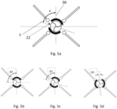
- Figs. 5a to 5d illustrate schematically an example of the changing geometry of the system as the turbine-surrounding structure 20 rotates over a range of angles.
- the turbine-surrounding structure 20 can also rotate to accommodate changing wind direction.
- Fig. 5a shows the rotation of the turbine-surrounding structure 20 at an angle ⁇ as measured between the airflow axis 5 and the secondary axis SA of the system.
- Figs. 5b to 5d show the turbine-surrounding structure 20 at different rotational angles ⁇ 1, ⁇ 2, ⁇ n. The rotation may be continuous or stepwise at specific angles.
- Figs. 6a to 6d illustrate schematically an example of the changing geometry of the system as side panels 101, 102, 301, 302 rotate and change in length (extend or retract) to facilitate changing wind direction and/or wind speed.
- Fig. 6a shows the side panels 101, 102 rotating or changing in length.
- Fig. 6a shows an example where the wind direction is aligned with the system primary axis PA and wind amplitude is high.
- the side panels 101, 102 of the convergent section 1 contract to reduce in length and hence reduce their wind capture area.
- Fig. 6b shows an example where the wind direction is aligned with the system primary axis PA and wind amplitude is low.
- the side panels 101, 102 of the convergent section 1 extend to increase in length and hence increase their wind capture area.
- the example shown in Fig. 6b shows side panels 101, 102 at the inlet or convergent section 1 being at one opening angle ⁇ 1 and the side panels 301, 302 at the outlet or divergent section 3 being at a different opening angle ⁇ 2 from the pane.
- the opening angle ⁇ 1, ⁇ 2 may be the angle between the side panels 101, 102, 301 302 about the rotational axis of the at least one wind turbine 21.
- the opening angles ⁇ 1 and ⁇ 2 are adjusted according to wind speeds and wind directions in order to create optimal conditions for the rotation of the at least one wind turbine 21 and thus harvest maximum power.
- Fig. 6d shows another example where at the convergent section 1 (inlet) one side panel 101 is extended while the other side panel 102 is retracted, and similarly at the divergent section 3 (outlet) one side panel 302 is extended while the other side panel 301 is retracted to accommodate a direction of wind that is at an oblique angle to the primary system axis PA.
- the length of the side panels 101, 102, 301, 302 can also be adjustable in order to keep the edge of the panels within a certain envelope 6, envelope enclosure or operational envelope.
- the system may be operable within the operational envelope 6 by the side panels 101, 102, 301, 302 being configured to only be extendable and/or pivotable within the operational envelope 6.
- Figs. 7a1 to 7c1 illustrate schematically an example of the changing geometry of the system as side panels 101, 102, 301, 302 rotate, without change in their length and, in doing so, the edges of the side panels 101, 102, 301, 302 move beyond a virtual rectangular envelope 6.
- the envelope 6 is shown in a preferred embodiment as a rectangle. It may be possible in other cases to have an envelope 6 of different shape.
- a virtual envelope 6 is referred to, but in preferred embodiments the envelope 6 may be a physical construction.
- the system may comprise a housing and the housing may define an operational envelope 6 within which the side panels 101, 102, 301, 302 operate.
- the at least one wind turbine 21, turbine-surrounding structure 20 and side panels 101, 102, 301, 302 may be mounted in and/or to the housing.
- Such physical construction of an envelope 6 serves an important function regarding safety, by preventing people, animals, and birds to enter the system and reach the turbine 21 where they may get injured by the rotating turbine blades.
- the envelope 6 may also serve an aesthetics appearance function. Figs.
- 7a2 to 7c2 illustrate schematically an example of the changing geometry of the system as side panels 101, 102, 301, 302 rotate, and at the same time retract to reduce their length so that the edge of the side panels 101,102,301,302 stays within the envelope 6. If the envelope 6 is a physical structure, the angle of rotation of the side panels 101, 102, 301, 302 must be limited so that they do not interfere and impact the envelope 6.
- the first opening 22 and second opening 23 are fixed so that the angles ⁇ 1, ⁇ 2 (i.e. between walls of the turbine-surrounding structure 20) and the size of the openings 22, 23 remain constant. This is not always the case, and in another embodiment the angles ⁇ 1, ⁇ 2 can change according to wind speed and/or direction.
- the turbine-surrounding structure 20 may be operable to adjust angles ⁇ 1, ⁇ 2 defining the size of the openings 22, 23 according to wind speed and/or direction.
- FIGs. 8a1 to 8c1 illustrate schematically an example of the changing geometry of the system as the two members or walls 20a, 20b of the turbine-surrounding structure 20 rotate while maintaining a fixed relative position of one relative to the other so that angles ⁇ 1, ⁇ 2 remain constant.
- Figs. 8a2 to 8c2 illustrate schematically an example of the changing geometry of the system as the two members or walls 20a, 20b of the turbine-surrounding structure 20 rotate while also changing the relative position of one relative to the other. In doing so the angles ⁇ 1, ⁇ 2 change and one increases while the other decreases.
- the members 20a, 20b are part of a single or unitary turbine-surrounding structure 20 and move together as that structure 20 rotates, as characteristically shown by means of an example in Figs. 8a1 to 8c1 .
- the walls 20a, 20b are separate structures, actuated independently and rotate in a way that results in the angles ⁇ 1, ⁇ 2 changing as each of the walls 20a, 20b rotate, as characteristically shown by means of an example in Figs. 8a2 to 8c2 .
- Figs. 9a to 9c illustrate schematically examples of alternative geometries of the turbine-surrounding structure 20.
- the turbine-surrounding structure 20 that surrounds the turbine 21 and its two walls 20a, 20b may have a concave shape (as seen from the turbine 21 side), may have a flat shape 21a, 21b and/or may have a convex shape 22a, 22b.
- the shape of the turbine-surrounding structure 20 is dependent on the type of turbine 21 itself and on the geometry of the walls 20a, 20b, 21a, 21b, 22a, 22b of the convergent and divergent sections 1, 3 and the side panels 101, 102, 301, 302 that they comprise of.
- Figs. 10a and 10b illustrate schematically an example of the effect of the geometry of the side panels 101, 102, 301, 302, in this example side panels 301, 302 at the downstream direction.
- Fig. 10a shows the flow at exit from the divergent section 3 as turbulence 310 may be created at the tips of the side panels 301, 302.
- the side panels 303,304 of the divergent section 3 may have a curved or airfoil profiled section to provide desired flow effects, in the example of Fig. 10b shown as a more laminar flow.
- turbulent effects downstream may be beneficial for increasing the pressure differential across inlet and outlet of the turbine 21, i.e. across the convergent section 1 and divergent section 3.
- Fig. 10c illustrates schematically one embodiment where turbulent effects 310 downstream are intentionally created through the use of flaps 301f, 302f.
- flaps 301f, 302f may pivot or otherwise move and adapt their geometry in order to enhance or diminish these downstream turbulent effects 310 depending on wind speed and system power performance.
- the system may comprise the flaps 301f, 302f.
- the flaps 301f, 302f may be mounted to and/or extend from the outer ends of the side panels 301, 302 of the divergent section 3 away from the at least one turbine 21.
- the flaps 301f, 302f may be mounted to pivot relative to the outer ends of the side panels 301, 302.
- Figs. 10d and 10e illustrate schematically another example of the effect of the geometry of the side panels 101, 102, in this example side panels 101, 102 at the upstream direction or in the convergent section 1.
- Side panels 103,104 are in this example curved.
- the side panels 103, 104 may be convex as seen from the wind flow side (i.e. from A2 in Fig. 10e ).
- Side panels 103, 104 of a curved profile enable a greater capture area for wind where A2>A1. Another advantage of curved side panels 103, 104 is that flow may be more laminar avoiding turbulence 105, 106 created at the tips of the side panels 103, 104.
- the exact profile of the side panels 103, 104 can be shaped according to alternative embodiments. The Figures only illustrate general principles by means of examples.
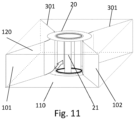
- Fig. 11 illustrates one example of a three-dimensional construction of an embodiment the system of this disclosure.
- a floor 110 and a roof 120 are formed on either side of the side panels 101, 102, 301, 302, a floor 110 and a roof 120 are formed.
- the roof 120 and the floor 110 can take many alternative geometries.
- Fig. 11 shows by example one embodiment where roof 120 and floor 110 are flat structures.
- the housing may comprise the roof 120 and floor 110.
- the turbine-surrounding structure 20, at least one wind turbine 21, convergent section 1, divergent section 3 and side panels 101, 102, 301, 302 may be mounted between the roof 120 and the floor 110.
- the edges of the side panels 101, 102, 301, 302 adjacent to the roof 120 and floor 110 may be substantially flush therewith such that wind substantially cannot flow therebetween.
- Fig. 12 illustrates one example of a three-dimensional construction of an alternative embodiment of the system of this disclosure wherein the turbine 21 extends above the top surface of the turbine-surrounding structure 20 and/or side panels 101, 102, 301, 302.
- the extension part of the turbine 21 is marked 21x.
- the system responds to changing wind conditions.
- the system comprises a controller 7 directly linked to a weather station 8 and a set of actuators 108, 109, 308, 309, 25 as illustrated by means of example in Fig. 13 .
- the controller 7 is also connected to the cloud 9 (for example an external network) for communication to a remote server or some other remote control and processing device.
- the controller 7 comprises a processor and a memory, a software program stored in the memory for running an algorithm to determine optimal system configuration under different wind conditions, and data stored in the memory. This data comprises models of the behaviour of the system, equations or look-up tables.
- the controller 7 is connected to the actuators 108, 109, 308, 309, 25 and controls these actuators 108, 109, 308, 309, 25 to adapt the geometry of the system in order to achieve optimal performance.
- the system may comprise first actuators 108, 308 are for controlling the rotation or pivoting of the side panels101, 102, 301, 302.
- the system may comprise second actuators 109, 309 are for controlling the extension or retraction in length of the side panels 101, 102, 301, 302.
- the system may comprise actuators 25 for controlling the rotation of the turbine-surrounding structure 20.
- the controller 7 may make decisions by combining current measurements and historical data.
- the objective sought by the algorithm run by the controller 7 is to maximise the energy harvested over a time period. This time period can comprise minutes, hours and/or days and the exact time period is determined dynamically based on measured and forecasted weather data and historical data that includes weather conditions, power efficiency and energy yield.
- the controller 7 is connected via wireless connection to the internet, the cloud 9 and via the cloud 9 to remote server or other devices.
- Other devices may include for example a smart phone of a responsible person. It is possible for controller 7 decisions to be externally overwritten.
- Data communication via the wireless connection comprises the transmission of data about system status, system performance, weather and other measurements. It further comprises the receiving of data about weather forecast, other relevant data.
- the controller 7 takes decisions by combining current measurements and historical data. Historical data may concern wind speed and direction as well as instantaneous electrical power produced by the turbine 21. The controller 7 takes decisions also considering system stability in view of measured or anticipated perturbations (changes are relatively high frequency) of the wind speed and direction. In some many cases it may be preferred to sacrifice some performance in terms of energy harvested in order to safeguard the stability of the system.
Description
- The present disclosure relates to a system for harnessing or generating energy from wind. The system may be particularly for improving efficiency of vertical axis wind turbines for all wind directions. The present disclosure further provides a method of operating such a system.
- One important area of renewable energy exploitation is harnessing of wind power in urban environments. One way to do this is to install wind turbines on roofs of buildings. In an urban environment the turbine itself is typically limited in size, and this requires that system installations can capture the greatest possible volume of wind and direct it and accelerate it towards the turbine to achieve the greatest possible energy generation efficiency. In an urban environment wind speeds often change quickly, and thus being able to capture wind from different directions is critical for overall system performance throughout the 24-hour day and throughout the 365 days of the year. An urban environment also requires that an installation is not too noisy, can be installed easily within the size limitations imposed by different town planning regulations, and is inconspicuous.
- There are several known disclosures and apparatuses relating to wind acceleration, for wind turbines, using convergent or divergent sections or both. There are several patents that seek to improve performance of wind turbines in an urban environment by capturing and accelerating wind flow. Generally, such devices include a convergent chamber for air inlet, a chamber that houses a wind turbine, and a diffusing chamber. Existing patents focus on improving laminar flow, increasing the pressure differential from inlet and outlet, obtaining maximum wind acceleration.
-
US9249807B2 -
US6638005B2 discloses a rotatable turbine housing having an air inlet opening and an air outlet opening. Although a rotatable turbine housing can respond to changing wind directions, it is inevitably a heavy and bulky structure that may not be suitable for installation on roofs of buildings. -
US9593666B2 -
US20130136576A1 describes a system having an inlet portion comprising vane so that the channel at the inlet portion is divided into a number of flow paths leading towards the wind turbine to focus the air pressure in front of the wind turbine to improve the effect of the air velocity on the wind turbine. This system may be able to provide some improved performance when the wind direction is essentially aligned with the primary axis through the inlet portion, but it does nothing to assist performance when the wind direction changes and is out of alignment with the primary axis through the inlet portion. -
US8821117B2 also discloses a system with a convergent section for an air inlet, a section housing the turbine, and a divergent section at an exit and focuses on the ratios of these sections for optimal performance. There is no means of dealing with changing wind direction. -
EP2013174534 -
DE10331682A1 discloses a system having at the flow inlet at least one guide fin, which, together with the upstream guide surface, delimits a flow channel that tapers towards its mouth and accelerates the flow. The use of guide fins can be helpful in conditioning the air flow at inlet and make the system less sensitive to small variations of the wind direction as long as it is essentially aligned with the primary axis of the system. When the wind direction changes significantly then these systems cannot accommodate the change in wind direction and performance can drop significantly. - A number of patents disclose systems that are intended for mounting on rooftops, but for these systems the entire structure is rotating. For example,
US20100032954A1 describes a system comprising two counter-rotating rotors. The rotors are mounted between two opposing aerofoils; the aerofoils and the rotors together being mounted on a turntable. The fact that the entire turntable rotates means that only small turbines (rotors) can be used with such system and hence overall energy yield is small. -
US8232664 discloses a turbine surrounded by a structure comprising diverter doors (panels) for controlling the air impinging on the turbine blades. Theses diverter doors are closable in high wind conditions to seal off the wind turbine to protect the turbine against damage. The turbine is aimed at protecting the turbine in conditions of high wind. The structure with open doors at all sides does not allow concentration of air flow. - Other patents describe static structures that surround a turbine, and which static structures are open at all sides. For example,
KR102026980B1 US5852331 andUS9951628 -
US 2003/133782 A1 , entitled "Coaxial Wind Turbine Apparatus Having a Closeable Air Inlet Opening," discloses a coaxial wind turbine apparatus which includes a pair of rearward-mounted, spring-loaded fins to orient the air inlet opening to face the direction of the oncoming wind and close a damper panel or shutter array at the air inlet opening during high wind conditions. -
US 2019/257281 A1 , entitled "Bi-Directional Scalable Turbine," discloses a passive turbine unit that uses the flow of water or air to rotate a main runner and electricity from streams, rivers, tidal water and high wind areas. The turbine units are capable of working in a bi-directional flow of water or air. -
CA 2 645 296 A1 -
JP 20022 76532 A - The prior art does not sufficiently address system efficiency at different wind directions. There is therefore the need for a system that can provide enhanced efficiency in harvesting the energy of the wind over a long period of time by adapting to the changing conditions of wind speed and wind direction. This system must be compatible to the constraints that are found for installations on top of buildings in relation to height, space, safety and aesthetics. An objective of this disclosure is to provide an enhanced and enclosed wind capturing apparatus for building rooftops, capable of capturing and accelerating wind flows and maximising the energy harvested, at all conditions, without having to rotate the complete apparatus.
- The present invention therefore provides a system and method in accordance with the claims. The present disclosure provides a system in accordance with
claim 1. The present disclosure also provides a method of operating a system in accordance with claim 13. - The disclosure refers to a system for improving efficiency of vertical axis wind turbines. One of the advantages of vertical axis wind turbines is that they can capture wind from all directions. However, when the turbine is surrounded by an enclosure or fins for accelerating air flow to improve efficiency, it generally suffers in that the turbine can no longer capture wind from all directions. This disclosure focuses on providing a surrounding structure to a turbine that can accelerate air flow and improve turbine efficiency while at the same time being able to adapt to changing wind directions so that efficiency of a vertical axis turbine can be improved while maintaining its omnidirectional characteristic. The disclosure is suitable for installations at the roof of buildings.
- The system captures and accelerates wind towards a turbine, and is capable of adjusting its geometry and configuration to maintain good performance for different wind speeds and wind directions.
- The present disclosure relates to a system that can adapt to changing wind speed and direction, in order to maximise the energy harvested by a wind turbine; this wind turbine is placed inside an enclosure, having an inlet convergent section to capture and accelerate the wind and an outlet divergent section. The geometry of the enclosure can adapt to achieve the geometry that will yield the best performance in harvesting the energy of the wind. The system is designed to work well in an urban environment and specifically on rooftops, having to comply with all the constraints of having such a system on building rooftops.
- The system may be for maximising the energy harnessed from the wind. The system may be for use with at least one wind turbine and may be aimed at increasing the air velocity contacting said wind turbine.
- Modifying at least two of the side panels may comprise adjusting an opening angle between at least two side panels of the convergent section and/or at least two side panels of the divergent section. Modifying at least two of the side panels may alternatively or additionally comprise extending or retracting the side panels to adjust their length, which may be their dimension in a direction away from a rotational axis of the at least one wind turbine. The side panels may each be rotatable about a pivot. A pivot axis of each pivot may be parallel to the rotational axis of the at least one wind turbine.
- The turbine-surrounding structure may be adjustable in use by being rotatable in use, such as by being rotatable around the at least one wind turbine such as around the outer circumference thereof. The turbine-surrounding structure may be adjustable in use by (a) the openings being adjustable in position or orientation relative to the wind turbine and/or convergent and divergent sections and/or (b) the size of the openings being adjustable.
- The present disclosure provides a system for maximising the energy harnessed from the wind, for use with at least one wind turbine and aimed at increasing the air velocity contacting said wind turbine, said apparatus comprising: a convergent section, said convergent section comprising an entry and an exit, said entry having an area higher than said exit, said convergent section having a first ratio being the entry area over the exit area; a wind turbine section adjacent to said exit of said convergent section, said wind turbine section comprising said at least one wind turbine; a divergent section adjacent to said wind turbine section, said divergent section comprising an entry and an exit, said entry having an area lower than said exit, wherein at least one of the convergent section and the divergent section comprises a cross-section having four sides, each of said four sides comprising side panels, characterised in that: at least two or more of said side panels can be modified in order to maximise the amount of energy harnessed within a time interval in accordance to wind direction and wind speed, and further characterised in that said wind turbine section comprising turbine-surrounding structure that surrounds said wind turbine, said turbine-surrounding structure having openings for wind to pass from the convergent section, through the turbine section, and exit to the divergent section.
- By way of example only, embodiments of systems and methods of the present disclosure are now described with reference to, and as shown in, the accompanying drawings, in which:
-
Fig. 1 illustrates a schematic of the system showing its basic elements. -
Figs. 2a and 2b illustrate a schematic of the system showing a movement of the turbine-surrounding structure that surrounds the turbine from one position to another position at 90 degrees' rotation to accommodate change of wind direction. -
Figs. 3a to 3e illustrate schematically an example of the changing geometry of the system as side panels can rotate to accommodate different wind directions. -
Figs. 4a and 4b illustrate schematically an example of the changing geometry of the system as one of the side panels rotates over a range of angles. -
Figs. 5a to 5d illustrate schematically an example of the changing geometry of the system as the turbine-surrounding structure rotates over a range of angles. -
Figs. 6a to 6d illustrate schematically an example of the changing geometry of the system as side panels rotate and change in length (extend or retract) to facilitate changing wind direction and/or wind speed.Figs. 6a to 6d illustrate the improvement in the capture efficiency at angled winds. -
Figs. 7a1 to 7c1 illustrate schematically an example of the changing geometry of the system as side panels rotate, without change in their length and, in doing so, move beyond a virtual rectangular envelope. -
Figs. 7a2 to 7c2 illustrate schematically an example of the changing geometry of the system as side panels change in length (extend or retract) as they rotate in order to stay within a rectangular envelope. -
Figs. 8a1 to 8c1 illustrate schematically an example of the changing geometry of the system as the two members comprising the turbine-surrounding structure rotate while maintaining a fixed relative position of one relative to the other. -
Figs. 8a2 to 8c2 illustrate schematically an example of the changing geometry of the system as the two members comprising the turbine-surrounding structure rotate while also changing the relative position of one relative to the other. -
Figs. 9a to 9c illustrate schematically examples of alternative geometries of the turbine-surrounding structure. -
Figs. 10a and 10b illustrate schematically an example of the effect of the geometry of the side panels, in this example side panels at the downstream direction. -
Fig. 10c illustrates schematically one embodiment where turbulent effects downstream are intentionally created through the use of flaps. -
Figs. 10d and10e illustrate schematically an example of the effect of the geometry of the side panels, in this example side panels at the upstream direction.Figs. 10a to 10e illustrate the change in profile to affect the external flow. -
Fig. 11 illustrates one example of a three-dimensional construction of an embodiment of the system of this disclosure. -
Fig. 12 illustrates one example of a three-dimensional construction of an alternative embodiment of the system of this disclosure wherein the turbine extends above the top surface of the surrounding structure. -
Fig. 13 illustrates one example of a system having a controller and a weather station, with the controller controlling actuators for the movement of the system movable parts. - A core benefit of this disclosure is the ability of the system to adapt to changing wind conditions in order to maximise to total energy harvested over a period of time. The disclosure comprises a system or apparatus having three main sections as illustrated schematically in
Fig. 1 : aconvergent section 1, awind turbine section 2 and adivergent section 3. Theconvergent section 1 comprises an entry and an exit, said entry having an area higher than said exit. Theconvergent section 1 has a first ratio being the entry area over the exit area. The first ratio of the entry area over the exit area is greater than 1. - The
wind turbine section 2 is adjacent to the exit of theconvergent section 1, and thewind turbine section 2 comprises at least onewind turbine 21. The at least onewind turbine 21 may rotate about a rotational axis, which may be aligned substantially vertically. In a preferred embodiment thewind turbine 21 is a vertical axis turbine. In one embodiment, the vertical axis turbine is a Gorlov type turbine. The at least onewind turbine 21 may be mounted to a generator or the like for using the energy captured from the wind by the at least onewind turbine 21 and generating electricity. The at least onewind turbine 21 may capture energy from the wind by being operable to rotate when wind passes through the at least onewind turbine 21. The generator may convert the kinetic energy from rotation of the at least onewind turbine 21 into electrical energy. The term "in use" as used herein may refer to the operation of the system when thewind turbine 21 is rotating about its rotational axis and providing power for a generator. - The
divergent section 3, adjacent to thewind turbine section 2, also comprises an entry and an exit, the entry having an area lower than said exit. The entry of thedivergent section 3 may be adjacent thewind turbine section 2. At least one of theconvergent section 1 and thedivergent section 3 comprisesside panels wind turbine section 2. In particular, at least one of theconvergent section 1 and thedivergent section 3 comprises a cross-section having four sides, each of said four sides comprisingside panels side panels convergent section 1 anddivergent section 3 may comprise at least oneside panel side panels convergent section 1 anddivergent section 3. At least oneside panel convergent section 1 anddivergent section 3 may be modifiable in use, such as for maximising the amount of energy harnessed within a time interval in accordance with wind direction and/or wind speed. - The
side panels wind turbine 21 and along a length in a direction perpendicular to and away from the rotational axis of the at least onewind turbine 21. Theside panels wind turbine 21 in a direction perpendicular to the rotational axis of the at least onewind turbine 21. Theside panels wind turbine 21. - In one preferred embodiment, the modification of these
side panels side panels side panels side panels - Another core characteristic of the disclosure is that the
wind turbine section 2 comprises a central turbine-surrounding or enclosingstructure 20 that surrounds or at least partially surrounds thewind turbine 21. This turbine-surroundingstructure 20 hasopenings convergent section 1, through thewind turbine section 2, and exit to thedivergent section 3. The pivot points of theside panels structure 20. - The turbine-surrounding
structure 20 may comprise twoopenings wind turbine 21. Wind may be directed from theconvergent section 1, through afirst opening 22 of the turbine-surroundingstructure 20, through the at leastwind turbine 21, through asecond opening 23 of the turbine-surroundingstructure 20 and subsequently though thedivergent section 3. - The turbine-surrounding
structure 20 may be mounted between the at least onewind turbine 21 and theside panels structure 20 may be located downstream ofside panels convergent section 1 and may be located between theside panels convergent section 1 and the at least onewind turbine 21. The turbine-surroundingstructure 20 may be located upstream ofside panels divergent section 3 and may be located between theside panels divergent section 3 and the at least onewind turbine 21. In an embodiment wind from theconvergent section 1 must pass through at least oneopening 22 to enter the at least onewind turbine 21 and/or wind exiting the at least onewind turbine 21 must pass through at least oneopening 23 to reach thedivergent section 3. - The turbine-surrounding
structure 20 may surround the at least onewind turbine 21 other than at theopenings wind turbine 21 other than at theopenings structure 20 may extend substantially along at least 50% or at least 75% or all of the height of the at least onewind turbine 21, the height being the length of the at least onewind turbine 21 along its rotational axis. Theopenings structure 20 and/or at least onewind turbine 21. - The system may be thought of as having a primary axis PA and a secondary axis SA as shown in
Fig. 1 . The primary axis PA may define the primary orientation of the system and the air flow direction from theconvergent section 1, through thewind turbine section 2, to thedivergent section 3 when the turbine-surroundingstructure 20 has itsopenings wind turbine 21. - The orientation of the turbine-surrounding
structure 20 is adjustable for accommodating changes in wind direction and/or wind speed. The turbine-surroundingstructure 20 may be rotatable for alignment of theopenings Figs. 2a and 2b illustrate a schematic of the system showing a movement, adjustment or rotation of the turbine-surroundingstructure 20 that at least partially surrounds thewind turbine 21 from one position to another position at 90 degrees' rotation to accommodate change of wind direction. In one embodiment theside panels convergent section 1 or thedivergent section 3 may be stationery, and only the turbine-surroundingstructure 20 may be rotating. - As shown in
Figs. 2a and 2b , the turbine-surroundingstructure 20 may comprise at least twowalls walls structure 20 are separated by afirst opening 22 and asecond opening 23. The at least twowalls wind turbine 21 and may extend along a height parallel to the rotational axis of the at least onewind turbine 21. Eachwall - The size or width of the first and
second openings wind turbine 21 and are between the edges of the first andsecond openings walls structure 20 are configured, such as by being part of a single structure or being linked together, so that thefirst opening 22 andsecond opening 23 are fixed so that the angles φ1 and φ2 remain constant. The turbine-surroundingstructure 20 with its at least twowalls - Generally, and as shown by example in
Figs. 2a and 2b , a change in wind direction of 90 degrees (for example about the rotational axis) may require a corresponding rotation of the turbine-surroundingstructure 20. In some cases, a change of wind direction by more than 45 degrees may also render the rotation of the turbine-surroundingstructure 20 a required system response. Initially theinlet opening 22 may be aligned with the primary axis PA (for example along wind direction W1 inFig. 2a ). Upon a rotation of 90 degrees of the turbine-surroundingstructure 20, the inlet opening 22 of the system is aligned with the secondary axis SA of the system rather than the primary axis of the system PA. The turbine-surroundingstructure 20 may be rotatable by at least 90 degrees about the rotational axis of the at least onewind turbine 21 and may be fully rotatable around 360 degrees. The turbine-surroundingstructure 20 may be supported on rails and may be able to rotate at least 90 degrees about a centre axis of said turbine-surroundingstructure 20 or a rotational axis of the at least onewind turbine 21. - When the wind speed changes, the system may adapt by changing the opening of the
side panels convergent section 1 which acts as the air inlet and/or the opening of theside panels divergent section 3 which acts as the air outlet.Figs. 3a to 3f show by means of example alternative configurations that theside panels -
Figs. 4a and 4b illustrate schematically an example of the changing geometry of the system as one of theside panels 101 rotates over a range of angles. By reference to oneside panel 101,Fig. 4a illustrates schematically, by means of an example, a change of relative position by angle Θ1, Θ1, Θn, with reference to an initial position. In general, any one of the fourside panels side panel 101 inFig. 4b . - The rotation may be continuous or stepwise at specific angles.
-
Figs. 5a to 5d illustrate schematically an example of the changing geometry of the system as the turbine-surroundingstructure 20 rotates over a range of angles. In a similar way as theside panels Figs. 3a to 3f and4a to 4b , the turbine-surroundingstructure 20 can also rotate to accommodate changing wind direction.Fig. 5a shows the rotation of the turbine-surroundingstructure 20 at an angle ψ as measured between theairflow axis 5 and the secondary axis SA of the system.Figs. 5b to 5d show the turbine-surroundingstructure 20 at different rotational angles ψ1, ψ2, ψn. The rotation may be continuous or stepwise at specific angles. -
Figs. 6a to 6d illustrate schematically an example of the changing geometry of the system asside panels Fig. 6a shows theside panels Fig. 6a shows an example where the wind direction is aligned with the system primary axis PA and wind amplitude is high. Theside panels convergent section 1 contract to reduce in length and hence reduce their wind capture area. -
Fig. 6b shows an example where the wind direction is aligned with the system primary axis PA and wind amplitude is low. In this case theside panels convergent section 1 extend to increase in length and hence increase their wind capture area. The example shown inFig. 6b showsside panels convergent section 1 being at one opening angle α1 and theside panels divergent section 3 being at a different opening angle α2 from the pane. The opening angle α1, α2 may be the angle between theside panels wind turbine 21. - The example shown in
Fig. 6c showsside panels convergent section 1 being at one opening angle α1 and theside panels divergent section 3 being at an opening angle α2 from the pane where α1= α2. The opening angles α1 and α2 are adjusted according to wind speeds and wind directions in order to create optimal conditions for the rotation of the at least onewind turbine 21 and thus harvest maximum power. -
Fig. 6d shows another example where at the convergent section 1 (inlet) oneside panel 101 is extended while theother side panel 102 is retracted, and similarly at the divergent section 3 (outlet) oneside panel 302 is extended while theother side panel 301 is retracted to accommodate a direction of wind that is at an oblique angle to the primary system axis PA. - The length of the
side panels certain envelope 6, envelope enclosure or operational envelope. The system may be operable within theoperational envelope 6 by theside panels operational envelope 6. -
Figs. 7a1 to 7c1 illustrate schematically an example of the changing geometry of the system asside panels side panels rectangular envelope 6. Please note that in the illustrations, theenvelope 6 is shown in a preferred embodiment as a rectangle. It may be possible in other cases to have anenvelope 6 of different shape. - A
virtual envelope 6 is referred to, but in preferred embodiments theenvelope 6 may be a physical construction. For example, the system may comprise a housing and the housing may define anoperational envelope 6 within which theside panels wind turbine 21, turbine-surroundingstructure 20 andside panels envelope 6 serves an important function regarding safety, by preventing people, animals, and birds to enter the system and reach theturbine 21 where they may get injured by the rotating turbine blades. Theenvelope 6 may also serve an aesthetics appearance function.Figs. 7a2 to 7c2 illustrate schematically an example of the changing geometry of the system asside panels envelope 6. If theenvelope 6 is a physical structure, the angle of rotation of theside panels envelope 6. - In
Figs. 2a and 2b , thefirst opening 22 andsecond opening 23 are fixed so that the angles φ1, φ2 (i.e. between walls of the turbine-surrounding structure 20) and the size of theopenings structure 20 may be operable to adjust angles φ1, φ2 defining the size of theopenings - The sequence in
Figs. 8a1 to 8c1 illustrate schematically an example of the changing geometry of the system as the two members orwalls structure 20 rotate while maintaining a fixed relative position of one relative to the other so that angles φ1, φ2 remain constant. In contrast,Figs. 8a2 to 8c2 illustrate schematically an example of the changing geometry of the system as the two members orwalls structure 20 rotate while also changing the relative position of one relative to the other. In doing so the angles φ1, φ2 change and one increases while the other decreases. In one embodiment themembers structure 20 and move together as thatstructure 20 rotates, as characteristically shown by means of an example inFigs. 8a1 to 8c1 . In another embodiment, thewalls walls Figs. 8a2 to 8c2 . -
Figs. 9a to 9c illustrate schematically examples of alternative geometries of the turbine-surroundingstructure 20. The turbine-surroundingstructure 20 that surrounds theturbine 21 and its twowalls turbine 21 side), may have aflat shape convex shape structure 20 is dependent on the type ofturbine 21 itself and on the geometry of thewalls divergent sections side panels -
Figs. 10a and 10b illustrate schematically an example of the effect of the geometry of theside panels example side panels Fig. 10a shows the flow at exit from thedivergent section 3 asturbulence 310 may be created at the tips of theside panels divergent section 3 may have a curved or airfoil profiled section to provide desired flow effects, in the example ofFig. 10b shown as a more laminar flow. In some cases, turbulent effects downstream may be beneficial for increasing the pressure differential across inlet and outlet of theturbine 21, i.e. across theconvergent section 1 anddivergent section 3. -
Fig. 10c illustrates schematically one embodiment whereturbulent effects 310 downstream are intentionally created through the use offlaps flaps turbulent effects 310 depending on wind speed and system power performance. The system may comprise theflaps flaps side panels divergent section 3 away from the at least oneturbine 21. Theflaps side panels -
Figs. 10d and10e illustrate schematically another example of the effect of the geometry of theside panels example side panels convergent section 1. Side panels 103,104 are in this example curved. Theside panels Fig. 10e ). -
Side panels curved side panels turbulence side panels side panels - Many alternative embodiments are possible for the construction of the system.
Fig. 11 illustrates one example of a three-dimensional construction of an embodiment the system of this disclosure. On either side of theside panels floor 110 and aroof 120 are formed. Theroof 120 and thefloor 110 can take many alternative geometries.Fig. 11 shows by example one embodiment whereroof 120 andfloor 110 are flat structures. The housing may comprise theroof 120 andfloor 110. The turbine-surroundingstructure 20, at least onewind turbine 21,convergent section 1,divergent section 3 andside panels roof 120 and thefloor 110. The edges of theside panels roof 120 andfloor 110 may be substantially flush therewith such that wind substantially cannot flow therebetween. -
Fig. 12 illustrates one example of a three-dimensional construction of an alternative embodiment of the system of this disclosure wherein theturbine 21 extends above the top surface of the turbine-surroundingstructure 20 and/orside panels turbine 21 is marked 21x. - The system responds to changing wind conditions. To do that, the system comprises a
controller 7 directly linked to aweather station 8 and a set ofactuators Fig. 13 . Thecontroller 7 is also connected to the cloud 9 (for example an external network) for communication to a remote server or some other remote control and processing device. - The
controller 7 comprises a processor and a memory, a software program stored in the memory for running an algorithm to determine optimal system configuration under different wind conditions, and data stored in the memory. This data comprises models of the behaviour of the system, equations or look-up tables. Thecontroller 7 is connected to theactuators actuators first actuators second actuators side panels actuators 25 for controlling the rotation of the turbine-surroundingstructure 20. - The
controller 7 may make decisions by combining current measurements and historical data. The objective sought by the algorithm run by thecontroller 7 is to maximise the energy harvested over a time period. This time period can comprise minutes, hours and/or days and the exact time period is determined dynamically based on measured and forecasted weather data and historical data that includes weather conditions, power efficiency and energy yield. - The
controller 7 is connected via wireless connection to the internet, thecloud 9 and via thecloud 9 to remote server or other devices. Other devices may include for example a smart phone of a responsible person. It is possible forcontroller 7 decisions to be externally overwritten. Data communication via the wireless connection comprises the transmission of data about system status, system performance, weather and other measurements. It further comprises the receiving of data about weather forecast, other relevant data. - The
controller 7 takes decisions by combining current measurements and historical data. Historical data may concern wind speed and direction as well as instantaneous electrical power produced by theturbine 21. Thecontroller 7 takes decisions also considering system stability in view of measured or anticipated perturbations (changes are relatively high frequency) of the wind speed and direction. In some many cases it may be preferred to sacrifice some performance in terms of energy harvested in order to safeguard the stability of the system.
Claims (15)
- A system for harnessing energy from wind, said system comprising:a convergent section (1), said convergent section comprising an entry and an exit, said entry having an area higher than said exit;a wind turbine section (2) adjacent to said exit of said convergent section, said wind turbine section comprising at least one wind turbine (21);a divergent section (3) adjacent to said wind turbine section, said divergent section comprising an entry and an exit, said entry having an area lower than said exit,wherein at least one of the convergent section and the divergent section comprises side panels (10,30) extending away from the wind turbine section, andat least two of said side panels are modifiable in use for maximising the amount of energy harnessed within a time interval in accordance with wind direction and/or wind speed; andsaid wind turbine section comprises a turbine-surrounding structure (20) that at least partially surrounds said at least one wind turbine, wherein said turbine-surrounding structure:has openings (22,23) for wind to pass from the convergent section, through the turbine section, and exit to the divergent section; and the turbine-surrounding structure is characterized in that itis rotatable around the at least one wind turbine in use, such that the orientation of the turbine-surrounding structure and the openings are adjusted relative to the side panels.
- A system according to claim 1, further characterised in that said turbine-surrounding structure is supported on rails and is able to rotate at least 90 degrees about a centre axis of said turbine-surrounding structure or a rotational axis of the at least one wind turbine.
- A system according to claim 1 or 2, wherein said turbine-surrounding structure comprises two walls separated from each other by the openings, preferably wherein said walls:are connected and rotate in unison so that the angles and/or sizes of the openings remain constant; orcan rotate independently so that the angles and/or sizes of the openings can vary depending on wind conditions in order to optimise system performance.
- A system according to any one of the preceding claims, wherein said side panels can rotate independently or in unison in accordance with wind conditions for achieving optimal system performance, preferably wherein rotation of said side panels can be according to actual measurements of current wind conditions or in anticipation of mean wind direction over a future time period.
- A system according to any one of the preceding claims, further characterised in that said system comprises a primary axis and a secondary axis, wherein the primary axis defines the primary orientation of the system and the secondary axis is essentially perpendicular to the primary axis, and wherein the primary axis defines the air flow direction from the convergent section, through the turbine section, to the divergent section when the openings of the turbine-surrounding structure are aligned to the primary axis, and wherein said system is installed to a fixed structure such as a roof of a building with the primary axis aligned to the prevailing wind direction according to the regional wind rose.
- A system according to any one of the preceding claims, wherein said side panels:rotate about fixed pivot points, characterised in that said pivot points are adjacent to the turbine-surrounding structure of the turbine section;rotate to maintain an optimal inlet angle formed between the side panels of the convergent section in relation to an outlet angle formed between the side panels of the divergent section;are extendable or retractable to change their length for achieving optimal performance according to wind conditions; and/orare both rotatable and changeable in length, and said turbine-surrounding structure are rotatable, in a coordinated manner for achieving optimal performance according to wind conditions.
- A system according to any one of the preceding claims, wherein the turbine - surrounding structure is:essentially cylindrical having a concave shape as seen from the turbine side; orcurved having a convex shape as seen from the turbine side.
- A system according to any one of the preceding claims, further comprising:a set of actuators to effect movement of the moving parts of the system, wherein the moving parts comprise side panels and the turbine-surrounding structure;a wind measuring station to measure wind speed and direction;a controller comprising a processor and memory;a software program stored in the memory, said software program being configured to run an algorithm to determine optimal system configuration under different wind conditions;data stored in the memory, said data comprising models of the behaviour of the system, equations or look-up tables,wherein the controller is configured to, by the processor, take decisions for controlling the actuators to adapt the geometry of the system for achieving optimal performance over a time period, preferably wherein said controller is configured to take decisions by combining current measurements and historical data.
- A system according to claim 8, wherein said controller is configured to take decisions for maximising energy harvested over a period of time, wherein said time period comprises minutes, hours, and/or days and wherein the exact time period is determined dynamically, preferably wherein said time period is determined based on measured and forecasted weather data.
- A system according to claim 8 to 9, wherein controller decisions may be externally overwritten.
- A system according to any one of claims 8 to 10, further comprising a communication module for connecting to the internet and enabling communication of data, wherein said data is related to system status, system performance, weather and/or other measurements, and wherein the communication module is configured to receive data relating to a weather forecast, other data and/or possible overwrite instructions.
- A system according to any one of the preceding claims, further comprising an envelope enclosure, wherein said envelope enclosure allows wind to pass through the system unobstructed and provides safety for people and animals by preventing their direct access to moving parts of the system.
- A method of operating a system for harnessing energy from wind, the system comprising:a convergent section, said convergent section comprising an entry and an exit, said entry having an area higher than said exit;a wind turbine section adjacent to said exit of said convergent section, said wind turbine section comprising at least one wind turbine;a divergent section adjacent to said wind turbine section, said divergent section comprising an entry and an exit, said entry having an area lower than said exit;wherein at least one of the convergent section and the divergent section comprises side panels extending away from the wind turbine section,further wherein the wind turbine section comprises a turbine-surrounding structure that at least partially surrounds said at least one wind turbine and comprising openings for wind to pass from the convergent section, through the turbine section and exit to the divergent section,characterised in that the method comprises operating the system by:modifying at least two of the side panels for maximising the amount of energy harnessed within a time interval in accordance with wind direction and/or wind speed; androtating the turbine-surrounding structure around the at least one wind turbine, thereby adjusting the orientation of the turbine-surrounding structure and the openings relative to the side panels.
- A method as claimed in claim 13 wherein modifying at least two of the side panels comprises adjusting an angle between at least two adjacent side panels and/or extending or retracting the side panels to adjust their length.
- A method as claimed in claim 13 or claim 14 wherein rotating the turbine-surrounding structure comprises adjusting the orientation of the turbine-surrounding structure and the openings relative to the at least one wind turbine.
Applications Claiming Priority (2)
| Application Number | Priority Date | Filing Date | Title |
|---|---|---|---|
| GB2000212.7A GB2591448B (en) | 2020-01-08 | 2020-01-08 | System and method for improving efficiency of vertical axis wind turbines for all wind directions |
| PCT/EP2021/050357 WO2021140243A1 (en) | 2020-01-08 | 2021-01-11 | Systems and methods for harnessing energy from wind |
Publications (3)
| Publication Number | Publication Date |
|---|---|
| EP4088021A1 EP4088021A1 (en) | 2022-11-16 |
| EP4088021B1 true EP4088021B1 (en) | 2024-02-21 |
| EP4088021C0 EP4088021C0 (en) | 2024-02-21 |
Family
ID=69527962
Family Applications (1)
| Application Number | Title | Priority Date | Filing Date |
|---|---|---|---|
| EP21700525.5A Active EP4088021B1 (en) | 2020-01-08 | 2021-01-11 | Systems and methods for harnessing energy from wind |
Country Status (6)
| Country | Link |
|---|---|
| US (1) | US20230053124A1 (en) |
| EP (1) | EP4088021B1 (en) |
| AU (1) | AU2021206041A1 (en) |
| CA (1) | CA3167374A1 (en) |
| GB (1) | GB2591448B (en) |
| WO (1) | WO2021140243A1 (en) |
Families Citing this family (2)
| Publication number | Priority date | Publication date | Assignee | Title |
|---|---|---|---|---|
| CN113847197B (en) * | 2020-06-28 | 2023-02-28 | 北京金风科创风电设备有限公司 | Wind generating set and rotation avoiding speed control method and device thereof |
| US20230009262A1 (en) * | 2021-07-07 | 2023-01-12 | Rajat Sood | System for harvesting energy from fluids in motion |
Family Cites Families (46)
| Publication number | Priority date | Publication date | Assignee | Title |
|---|---|---|---|---|
| US570123A (en) * | 1896-10-27 | Windmill | ||
| US1922866A (en) * | 1932-04-22 | 1933-08-15 | Rosenberg Sandor | Rotary airfoil |
| US3249160A (en) * | 1964-06-10 | 1966-05-03 | Messerschmitt Ag | Rotor blade construction for aircraft |
| US3666210A (en) * | 1969-12-18 | 1972-05-30 | Hitco Gardena | Variable aerodynamic structure |
| EP0200823B1 (en) * | 1985-04-26 | 1988-12-28 | JAMES HOWDEN & COMPANY LIMITED | Wind turbine |
| US4834610A (en) * | 1986-04-25 | 1989-05-30 | Bond Iii Frederick W | Wind processing air turbine, and methods of constructing and utilizing same |
| US5203520A (en) * | 1991-10-28 | 1993-04-20 | Jozef Przygodzki | Helicar |
| US5375968A (en) * | 1993-06-02 | 1994-12-27 | Kollitz; Gerhard | Wind turbine generator |
| US5852331A (en) | 1996-06-21 | 1998-12-22 | Giorgini; Roberto | Wind turbine booster |
| JP2002276532A (en) * | 2001-03-21 | 2002-09-25 | Tsutomu Komatsu | Generating method using building wind and generating device therefor |
| US6674181B2 (en) * | 2001-12-31 | 2004-01-06 | Charles C. Harbison | Wind-driven twin turbine |
| US6638005B2 (en) * | 2002-01-17 | 2003-10-28 | John W. Holter | Coaxial wind turbine apparatus having a closeable air inlet opening |
| US6902370B2 (en) * | 2002-06-04 | 2005-06-07 | Energy Unlimited, Inc. | Telescoping wind turbine blade |
| US6740989B2 (en) * | 2002-08-21 | 2004-05-25 | Pacifex Management Inc. | Vertical axis wind turbine |
| DE10331682A1 (en) | 2003-07-14 | 2005-02-10 | Gehrke, Dieter | Wind power facility for generating current has rotors with a vertical axis of rotation and rotor blades distributed in a peripheral direction with equal gaps around a free cross-flow chamber |
| US7581926B1 (en) * | 2004-03-22 | 2009-09-01 | Clipper Windpower Technology, Inc. | Servo-controlled extender mechanism for extendable rotor blades for power generating wind and ocean current turbines |
| US7582977B1 (en) * | 2005-02-25 | 2009-09-01 | Clipper Windpower Technology, Inc. | Extendable rotor blades for power generating wind and ocean current turbines within a module mounted atop a main blade |
| TWM279736U (en) * | 2005-07-14 | 2005-11-01 | Jetpo Technology Inc | Improved mechanism of a wind power generator |
| GB0521129D0 (en) | 2005-10-18 | 2005-11-23 | Law Jonathan A | A wind turbine |
| US7242108B1 (en) * | 2005-10-27 | 2007-07-10 | Dablo Oliver P | Wind-actuated electric power alternator |
| US8174135B1 (en) * | 2006-07-10 | 2012-05-08 | Roe Justin C | Marine energy hybrid |
| MX2009000552A (en) * | 2006-07-21 | 2009-01-28 | Clipper Windpower Technology | Retractable rotor blade structure. |
| BRPI0906663A2 (en) * | 2008-01-30 | 2015-07-14 | Clipper Windpower Inc | Retractable paddle frame with a split trailing edge |
| US8186960B2 (en) * | 2008-04-15 | 2012-05-29 | Frontier Pro Services, Llc | Repair of rotor blade roots |
| US8192161B2 (en) * | 2008-05-16 | 2012-06-05 | Frontier Wind, Llc. | Wind turbine with deployable air deflectors |
| US8267654B2 (en) * | 2008-05-16 | 2012-09-18 | Frontier Wind, Llc | Wind turbine with gust compensating air deflector |
| CA2633876A1 (en) | 2008-06-05 | 2009-12-05 | Organoworld Inc. | Wind turbine apparatus |
| US8232664B2 (en) * | 2008-08-25 | 2012-07-31 | Mark R. Stroup | Vertical axis wind turbine |
| CA2645296A1 (en) * | 2008-11-27 | 2010-05-27 | Organoworld Inc. | Annular multi-rotor double-walled turbine |
| US8231347B2 (en) * | 2009-02-04 | 2012-07-31 | Frontier Wind, Llc | Mass-centralizing blade extension drive mount locations for wind turbine |
| US8206107B2 (en) * | 2009-04-13 | 2012-06-26 | Frontier Wind, Llc | Variable length wind turbine blade having transition area elements |
| US7946802B1 (en) * | 2010-04-13 | 2011-05-24 | Seven International Group, Inc. | Wind turbine utilizing wind directing slats |
| AU2011274315B2 (en) | 2010-06-30 | 2016-11-17 | Sebastian Wojnar | A wind turbine air flow device |
| AT510208B1 (en) * | 2010-08-04 | 2012-05-15 | Penz Alois | WIND TURBINE |
| US9249807B2 (en) | 2011-01-03 | 2016-02-02 | Yup Power Inc. | Fluidic flow capture and acceleration apparatus for hyper-conversion |
| BE1020677A3 (en) | 2012-05-08 | 2014-03-04 | Devisch Geert | WIND TURBINE AND BUILDING INCLUDING SUCH WIND TURBINE. |
| US9013054B1 (en) | 2012-07-19 | 2015-04-21 | BX Power, LLC | Wind turbine with channels and roof air exhaust |
| CN104214038B (en) * | 2013-05-29 | 2016-12-28 | 杭州林东新能源科技股份有限公司 | Current weight adjustment device and the ocean power generating device of application thereof |
| US9835133B2 (en) * | 2013-08-22 | 2017-12-05 | King Fahd University Of Petroleum And Minerals | Electrical power generation system using renewable energy |
| US11448189B2 (en) * | 2014-02-24 | 2022-09-20 | Paul C. Dietzel | Power generation and propulsion architecture using fluid flow |
| US9745960B2 (en) * | 2014-02-24 | 2017-08-29 | Paul C. Dietzel | Power generation architecture using environmental fluid flow |
| KR102026980B1 (en) | 2017-11-29 | 2019-10-01 | 이재윤 | Wind collection apparatus for wind turbine generator |
| MX2018001433A (en) * | 2018-02-01 | 2019-08-02 | Luis Javier Fierros Farell | Wind-based electrical power generation system. |
| CA3034183C (en) * | 2018-02-22 | 2021-03-16 | Ralph Dominic Raina | Single or bi-directional, scalable turbine |
| CA2997766C (en) * | 2018-03-08 | 2019-10-08 | Branko Mizerit | Vortex acceleration wind energy tower |
| EP3781802A2 (en) * | 2018-04-17 | 2021-02-24 | Kayara, Sammy | Wind-funneling for gas turbines |
-
2020
- 2020-01-08 GB GB2000212.7A patent/GB2591448B/en active Active
-
2021
- 2021-01-11 WO PCT/EP2021/050357 patent/WO2021140243A1/en unknown
- 2021-01-11 EP EP21700525.5A patent/EP4088021B1/en active Active
- 2021-01-11 CA CA3167374A patent/CA3167374A1/en active Pending
- 2021-01-11 US US17/791,459 patent/US20230053124A1/en active Pending
- 2021-01-11 AU AU2021206041A patent/AU2021206041A1/en active Pending
Also Published As
| Publication number | Publication date |
|---|---|
| AU2021206041A1 (en) | 2022-09-01 |
| GB202000212D0 (en) | 2020-02-19 |
| EP4088021A1 (en) | 2022-11-16 |
| WO2021140243A1 (en) | 2021-07-15 |
| CA3167374A1 (en) | 2021-07-15 |
| US20230053124A1 (en) | 2023-02-16 |
| GB2591448A (en) | 2021-08-04 |
| GB2591448B (en) | 2023-05-03 |
| EP4088021C0 (en) | 2024-02-21 |
Similar Documents
| Publication | Publication Date | Title |
|---|---|---|
| US20230250797A1 (en) | Fluid turbine systems | |
| Wong et al. | Performance enhancements on vertical axis wind turbines using flow augmentation systems: A review | |
| US8786123B2 (en) | Turbine assembly | |
| DK2456974T3 (en) | WIND GENERATOR | |
| EP4088021B1 (en) | Systems and methods for harnessing energy from wind | |
| RU2541609C2 (en) | Pressure-controlled device for improvement of wind turbine parameters | |
| US20140356163A1 (en) | Turbomachine | |
| US10495063B2 (en) | Wind turbine | |
| KR20180116418A (en) | Wind power generator combined with building | |
| CN105240207A (en) | Wind turbine and method for guiding fluid flow by using wind turbine | |
| KR101236347B1 (en) | Turbine for generation of electricity by wind using construction for concentrating wind | |
| WO2014141214A1 (en) | Wind turbine and tower system | |
| US8063502B1 (en) | Shrouded wind turbine with dual coaxial airflow passageways | |
| US20140105738A1 (en) | Nozzle assembly for use with a wind lens system for the generation of electric power | |
| EP3597900B1 (en) | Wind turbine | |
| EP4083417A1 (en) | Method of operating a wind turbine system | |
| SG177024A1 (en) | Vertical-axis wind-turbine with stacked propellers and an inground road installation | |
| KR101985317B1 (en) | Transverse axis wind turbine | |
| GB2404699A (en) | A turbine | |
| KR20130116474A (en) | Wind power generation which has the air volume adjuster | |
| KR20110077491A (en) | Vertical axis wind turbines for power generation of the air flow control device | |
| KR20140092085A (en) | A wind power apparatus |
Legal Events
| Date | Code | Title | Description |
|---|---|---|---|
| STAA | Information on the status of an ep patent application or granted ep patent |
Free format text: STATUS: UNKNOWN |
|
| STAA | Information on the status of an ep patent application or granted ep patent |
Free format text: STATUS: THE INTERNATIONAL PUBLICATION HAS BEEN MADE |
|
| PUAI | Public reference made under article 153(3) epc to a published international application that has entered the european phase |
Free format text: ORIGINAL CODE: 0009012 |
|
| STAA | Information on the status of an ep patent application or granted ep patent |
Free format text: STATUS: REQUEST FOR EXAMINATION WAS MADE |
|
| 17P | Request for examination filed |
Effective date: 20220706 |
|
| AK | Designated contracting states |
Kind code of ref document: A1 Designated state(s): AL AT BE BG CH CY CZ DE DK EE ES FI FR GB GR HR HU IE IS IT LI LT LU LV MC MK MT NL NO PL PT RO RS SE SI SK SM TR |
|
| DAV | Request for validation of the european patent (deleted) | ||
| DAX | Request for extension of the european patent (deleted) | ||
| GRAP | Despatch of communication of intention to grant a patent |
Free format text: ORIGINAL CODE: EPIDOSNIGR1 |
|
| STAA | Information on the status of an ep patent application or granted ep patent |
Free format text: STATUS: GRANT OF PATENT IS INTENDED |
|
| INTG | Intention to grant announced |
Effective date: 20230927 |
|
| GRAS | Grant fee paid |
Free format text: ORIGINAL CODE: EPIDOSNIGR3 |
|
| GRAA | (expected) grant |
Free format text: ORIGINAL CODE: 0009210 |
|
| STAA | Information on the status of an ep patent application or granted ep patent |
Free format text: STATUS: THE PATENT HAS BEEN GRANTED |
|
| AK | Designated contracting states |
Kind code of ref document: B1 Designated state(s): AL AT BE BG CH CY CZ DE DK EE ES FI FR GB GR HR HU IE IS IT LI LT LU LV MC MK MT NL NO PL PT RO RS SE SI SK SM TR |
|
| REG | Reference to a national code |
Ref country code: GB Ref legal event code: FG4D |
|
| REG | Reference to a national code |
Ref country code: CH Ref legal event code: EP |
|
| REG | Reference to a national code |
Ref country code: DE Ref legal event code: R096 Ref document number: 602021009598 Country of ref document: DE |
|
| REG | Reference to a national code |
Ref country code: IE Ref legal event code: FG4D |
|
| U01 | Request for unitary effect filed |
Effective date: 20240319 |
|
| U07 | Unitary effect registered |
Designated state(s): AT BE BG DE DK EE FI FR IT LT LU LV MT NL PT SE SI Effective date: 20240322 |