EP4087976B1 - Fliesensystem und verfahren zum zusammenbau eines fliesensystems - Google Patents
Fliesensystem und verfahren zum zusammenbau eines fliesensystems Download PDFInfo
- Publication number
- EP4087976B1 EP4087976B1 EP21700395.3A EP21700395A EP4087976B1 EP 4087976 B1 EP4087976 B1 EP 4087976B1 EP 21700395 A EP21700395 A EP 21700395A EP 4087976 B1 EP4087976 B1 EP 4087976B1
- Authority
- EP
- European Patent Office
- Prior art keywords
- tile
- channels
- underside
- cable
- adjacent
- Prior art date
- Legal status (The legal status is an assumption and is not a legal conclusion. Google has not performed a legal analysis and makes no representation as to the accuracy of the status listed.)
- Active
Links
Images


Classifications
-
- E—FIXED CONSTRUCTIONS
- E04—BUILDING
- E04B—GENERAL BUILDING CONSTRUCTIONS; WALLS, e.g. PARTITIONS; ROOFS; FLOORS; CEILINGS; INSULATION OR OTHER PROTECTION OF BUILDINGS
- E04B5/00—Floors; Floor construction with regard to insulation; Connections specially adapted therefor
- E04B5/48—Special adaptations of floors for incorporating ducts, e.g. for heating or ventilating
-
- E—FIXED CONSTRUCTIONS
- E04—BUILDING
- E04F—FINISHING WORK ON BUILDINGS, e.g. STAIRS, FLOORS
- E04F15/00—Flooring
- E04F15/02—Flooring or floor layers composed of a number of similar elements
- E04F15/02194—Flooring consisting of a number of elements carried by a non-rollable common support plate or grid
-
- E—FIXED CONSTRUCTIONS
- E01—CONSTRUCTION OF ROADS, RAILWAYS, OR BRIDGES
- E01C—CONSTRUCTION OF, OR SURFACES FOR, ROADS, SPORTS GROUNDS, OR THE LIKE; MACHINES OR AUXILIARY TOOLS FOR CONSTRUCTION OR REPAIR
- E01C9/00—Special pavings; Pavings for special parts of roads or airfields
- E01C9/08—Temporary pavings
-
- E—FIXED CONSTRUCTIONS
- E01—CONSTRUCTION OF ROADS, RAILWAYS, OR BRIDGES
- E01C—CONSTRUCTION OF, OR SURFACES FOR, ROADS, SPORTS GROUNDS, OR THE LIKE; MACHINES OR AUXILIARY TOOLS FOR CONSTRUCTION OR REPAIR
- E01C11/00—Details of pavings
- E01C11/24—Methods or arrangements for preventing slipperiness or protecting against influences of the weather
- E01C11/26—Permanently installed heating or blowing devices ; Mounting thereof
- E01C11/265—Embedded electrical heating elements ; Mounting thereof
-
- E—FIXED CONSTRUCTIONS
- E01—CONSTRUCTION OF ROADS, RAILWAYS, OR BRIDGES
- E01C—CONSTRUCTION OF, OR SURFACES FOR, ROADS, SPORTS GROUNDS, OR THE LIKE; MACHINES OR AUXILIARY TOOLS FOR CONSTRUCTION OR REPAIR
- E01C13/00—Pavings or foundations specially adapted for playgrounds or sports grounds; Drainage, irrigation or heating of sports grounds
- E01C13/02—Foundations, e.g. with drainage or heating arrangements
-
- E—FIXED CONSTRUCTIONS
- E01—CONSTRUCTION OF ROADS, RAILWAYS, OR BRIDGES
- E01C—CONSTRUCTION OF, OR SURFACES FOR, ROADS, SPORTS GROUNDS, OR THE LIKE; MACHINES OR AUXILIARY TOOLS FOR CONSTRUCTION OR REPAIR
- E01C13/00—Pavings or foundations specially adapted for playgrounds or sports grounds; Drainage, irrigation or heating of sports grounds
- E01C13/04—Pavings made of prefabricated single units
- E01C13/045—Pavings made of prefabricated single units the prefabricated single units consisting of or including bitumen, rubber or plastics
-
- E—FIXED CONSTRUCTIONS
- E01—CONSTRUCTION OF ROADS, RAILWAYS, OR BRIDGES
- E01C—CONSTRUCTION OF, OR SURFACES FOR, ROADS, SPORTS GROUNDS, OR THE LIKE; MACHINES OR AUXILIARY TOOLS FOR CONSTRUCTION OR REPAIR
- E01C17/00—Pavement lights, i.e. translucent constructions forming part of the surface
-
- E—FIXED CONSTRUCTIONS
- E01—CONSTRUCTION OF ROADS, RAILWAYS, OR BRIDGES
- E01C—CONSTRUCTION OF, OR SURFACES FOR, ROADS, SPORTS GROUNDS, OR THE LIKE; MACHINES OR AUXILIARY TOOLS FOR CONSTRUCTION OR REPAIR
- E01C5/00—Pavings made of prefabricated single units
- E01C5/20—Pavings made of prefabricated single units made of units of plastics, e.g. concrete with plastics, linoleum
-
- E—FIXED CONSTRUCTIONS
- E01—CONSTRUCTION OF ROADS, RAILWAYS, OR BRIDGES
- E01C—CONSTRUCTION OF, OR SURFACES FOR, ROADS, SPORTS GROUNDS, OR THE LIKE; MACHINES OR AUXILIARY TOOLS FOR CONSTRUCTION OR REPAIR
- E01C9/00—Special pavings; Pavings for special parts of roads or airfields
- E01C9/08—Temporary pavings
- E01C9/086—Temporary pavings made of concrete, wood, bitumen, rubber or synthetic material or a combination thereof
-
- E—FIXED CONSTRUCTIONS
- E04—BUILDING
- E04F—FINISHING WORK ON BUILDINGS, e.g. STAIRS, FLOORS
- E04F15/00—Flooring
- E04F15/02—Flooring or floor layers composed of a number of similar elements
-
- F—MECHANICAL ENGINEERING; LIGHTING; HEATING; WEAPONS; BLASTING
- F24—HEATING; RANGES; VENTILATING
- F24D—DOMESTIC- OR SPACE-HEATING SYSTEMS, e.g. CENTRAL HEATING SYSTEMS; DOMESTIC HOT-WATER SUPPLY SYSTEMS; ELEMENTS OR COMPONENTS THEREFOR
- F24D13/00—Electric heating systems
- F24D13/02—Electric heating systems solely using resistance heating, e.g. underfloor heating
- F24D13/022—Electric heating systems solely using resistance heating, e.g. underfloor heating resistances incorporated in construction elements
- F24D13/024—Electric heating systems solely using resistance heating, e.g. underfloor heating resistances incorporated in construction elements in walls, floors, ceilings
-
- F—MECHANICAL ENGINEERING; LIGHTING; HEATING; WEAPONS; BLASTING
- F24—HEATING; RANGES; VENTILATING
- F24D—DOMESTIC- OR SPACE-HEATING SYSTEMS, e.g. CENTRAL HEATING SYSTEMS; DOMESTIC HOT-WATER SUPPLY SYSTEMS; ELEMENTS OR COMPONENTS THEREFOR
- F24D3/00—Hot-water central heating systems
- F24D3/12—Tube and panel arrangements for ceiling, wall, or underfloor heating
- F24D3/14—Tube and panel arrangements for ceiling, wall, or underfloor heating incorporated in a ceiling, wall or floor
- F24D3/141—Tube mountings specially adapted therefor
- F24D3/142—Tube mountings specially adapted therefor integrated in prefab construction elements
-
- F—MECHANICAL ENGINEERING; LIGHTING; HEATING; WEAPONS; BLASTING
- F24—HEATING; RANGES; VENTILATING
- F24D—DOMESTIC- OR SPACE-HEATING SYSTEMS, e.g. CENTRAL HEATING SYSTEMS; DOMESTIC HOT-WATER SUPPLY SYSTEMS; ELEMENTS OR COMPONENTS THEREFOR
- F24D3/00—Hot-water central heating systems
- F24D3/12—Tube and panel arrangements for ceiling, wall, or underfloor heating
- F24D3/14—Tube and panel arrangements for ceiling, wall, or underfloor heating incorporated in a ceiling, wall or floor
- F24D3/141—Tube mountings specially adapted therefor
- F24D3/143—Tube clips with barbed anchors
-
- E—FIXED CONSTRUCTIONS
- E01—CONSTRUCTION OF ROADS, RAILWAYS, OR BRIDGES
- E01C—CONSTRUCTION OF, OR SURFACES FOR, ROADS, SPORTS GROUNDS, OR THE LIKE; MACHINES OR AUXILIARY TOOLS FOR CONSTRUCTION OR REPAIR
- E01C2201/00—Paving elements
- E01C2201/06—Sets of paving elements
-
- E—FIXED CONSTRUCTIONS
- E01—CONSTRUCTION OF ROADS, RAILWAYS, OR BRIDGES
- E01C—CONSTRUCTION OF, OR SURFACES FOR, ROADS, SPORTS GROUNDS, OR THE LIKE; MACHINES OR AUXILIARY TOOLS FOR CONSTRUCTION OR REPAIR
- E01C2201/00—Paving elements
- E01C2201/12—Paving elements vertically interlocking
-
- E—FIXED CONSTRUCTIONS
- E01—CONSTRUCTION OF ROADS, RAILWAYS, OR BRIDGES
- E01C—CONSTRUCTION OF, OR SURFACES FOR, ROADS, SPORTS GROUNDS, OR THE LIKE; MACHINES OR AUXILIARY TOOLS FOR CONSTRUCTION OR REPAIR
- E01C2201/00—Paving elements
- E01C2201/16—Elements joined together
-
- Y—GENERAL TAGGING OF NEW TECHNOLOGICAL DEVELOPMENTS; GENERAL TAGGING OF CROSS-SECTIONAL TECHNOLOGIES SPANNING OVER SEVERAL SECTIONS OF THE IPC; TECHNICAL SUBJECTS COVERED BY FORMER USPC CROSS-REFERENCE ART COLLECTIONS [XRACs] AND DIGESTS
- Y02—TECHNOLOGIES OR APPLICATIONS FOR MITIGATION OR ADAPTATION AGAINST CLIMATE CHANGE
- Y02B—CLIMATE CHANGE MITIGATION TECHNOLOGIES RELATED TO BUILDINGS, e.g. HOUSING, HOUSE APPLIANCES OR RELATED END-USER APPLICATIONS
- Y02B30/00—Energy efficient heating, ventilation or air conditioning [HVAC]
Definitions
- the invention relates to interlocking tiles for covering a surface of a building, structure or outdoor area.
- the surface is typically a floor and the tiles may be used as an easy way to change its appearance or its physical characteristics such as the surface material.
- the use of the tiles may be temporary, e.g. in a display area, or of unlimited duration, e.g. around a swimming pool or in a garage.
- Interlocking modular panels are well known as temporary ground coverings, for example to create temporary dance floors or routes for vehicles to travel across soft ground. They can also be put to more permanent use, e.g. to install wood flooring or to create a raised floor with a void underneath, which can be used for routing electrical or telecommunications cables. When used on a floor, such systems generally do not need to be fixed down: they can "float" and their own weight combined with engagement with the adjoining panels is sufficient to hold them on the substrate. Modular panel systems have the advantage of being relatively quick to install as a way of changing the appearance or physical characteristics of the floor, without the need to remove and replace the existing ground surface. They are also generally quick to remove when a temporary installation comes to an end or if access is needed to the ground below a permanent installation.
- Published patent application WO 2019/093893 A1 discloses a tile for laying under a top floor to dampen it.
- the tile comprises a grid of plate-shaped base members a grid of base members with U-shaped connectors between them.
- the connectors are open from above and are aligned to form channels that can receive an electrical or liquid conduit.
- Similar U-shaped connectors extend from the edges of each tile for coupling to apertures in adjacent, similar tiles.
- Published patent application GB 2568614 A describes a plastic moulding for guiding the layout of underfloor heating pipes. The mouldings can be clipped together edge-to-edge to cover the area of the floor.
- Published patent application WO 2015/061894 A1 discloses a tile for use in a modular flooring system, which includes a lattice framework of elongated rib members crisscrossing at right angles on the underside of a support grid structure and defining a network of cells.
- the tile also includes a plurality of first and second edge connectors by which adjacent tiles can be secured together.
- Published patent application US 2016/222674 A1 discloses an alternative modular floor tile in which the connection between adjacent tiles is provided by a laterally extending protrusion that engages a downward facing protrusion.
- the invention provides a tile system according to claim 1.
- the ability to lay cables under the tiles provides advantages: for example, to provide power or networking to equipment that may be placed on the tile assembly without creating a trip hazard. Because there are two sets of channels, which are typically orthogonal and intersecting, cables can be guided through the tile along many different paths. Special cables can be used to add lighting or to heat the tile assembly itself from below. In embodiments of the invention where a lighting cable under the tiles lights the floor surface through translucent inserts, it will be understood that this can be a cost-effective way to provide floor-level lighting for use in emergency situations.
- the tiles according to the invention may be made large enough to be quick and easy to install and to form a robust and stable structure, while retaining the freedom to create an enormous variety of decorative patterns, depending on how the inserts are arranged in the recesses. For example, if the recesses are arranged in a grid pattern over substantially the whole surface of the tile, the inserts can be arranged in the manner of a mosaic.
- the patterns formed by the inserts need not be purely decorative: for example, in some situations they could be used to define a route, form a directional indicator or highlight a hazard.
- the invention additionally provides a method of assembling a tile system according to claim 12.
- words such as “lower” and “under” refer to the direction towards the substrate on which the tile is mounted, while words such as “upper” and “over” refer to the opposite direction. These words therefore have their natural meaning when the substrate is a floor but the invention does not exclude mounting the tiles on substrates with other orientations, e.g. on a wall. Naturally, the tiles and other components of the invention may be manufactured, transported and stored in any orientation prior to use, without departing from the scope of the invention defined by the claims.
- Figure 1 illustrates various components of a modular tile assembly according to a first embodiment of the present invention.
- the assembly is intended to be laid on a flat substrate, such as a cement screed, to form a floor just above the substrate.
- the main area of the floor is constructed from a plurality of interlocking tiles 2.
- the tiles 2 are square in plan, though other tessellating shapes such as rectangles, hexagons or a combination of two or more different shapes could be used.
- the design of the illustrated tile 2 is such that it can be moulded as a single component in a two-part mould.
- the tiles are preferably formed from a plastic material, such as polypropylene, that is strong enough to carry the weight that is expected to be placed on the floor and hard enough to resist the wear of the activities that are expected to be carried out on it. For example, if vehicles are to be driven over the floor, it may need to be of a more robust material and/or design than for purely pedestrian use. Naturally, other considerations such as colour, grip, weather-resistance, sustainability, etc. may affect the choice of material.
- the tiles 2 are designed to interlock with one another so that they can cover an indefinite area of the substrate in modular fashion. As shown in Figure 1 , the main tiles 2 may also interlock with edge pieces 4 and corner pieces 6 at the edges of the desired area of floor.
- Each tile 2 is formed as a single moulding, structured as a grid of square cells 8, which in the illustrated embodiment form a 14 x 14 array.
- the cells 8 provide recesses 10 in the upper surface of the tile 2, into which inserts 12 can be pressed to form a desired pattern, as will be described in more detail below.
- every cell 8 has such a recess 10, although Figure 1 shows only one representative cell 8 that is occupied by an insert 12.
- smaller numbers of recesses 10 could be provided: for example, spread more sparsely over the whole area of the tile 2, confined to particular areas of the tile or arranged in pre-defined patterns.
- plain tiles with no recesses may be used alongside tiles according to the invention.
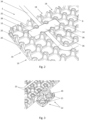
- the underside of such a plain tile 3 is shown in Figure 2 .
- the structure of the plain tile 3 is substantially the same as that of the tiles 2 according to the invention so Figure 2 is useful for understanding both kinds of tile.
- each cell 8 is substantially hollow.
- the walls between adjacent cells 8 take the form of arches 14, which spring from pillars 16 located at each intersection of the grid.
- the array of pillars 16 supports the floor above the substrate on which it rests.
- the lines of arches 14 along each row and column of the grid of cells 8 create first and second sets of channels 18 that open to the underside of the tile 2.
- the channels 18 extend parallel to the upper surface of the tile and at least some of the channels 18 emerge at openings 20 in the side edges of the tile.
- the first and second sets of channels 18 are orthogonal to one another and each cell 8 is located at the intersection of two channels 18.
- a system with hexagonal tiles might comprise three sets of channels and each cell would be located at the intersection of three channels angled at 60° to one another.
- each projection 22 has a substantially square boss 21 that fits into the hollow underside of a cell 8 of the adjacent tile.
- the boss 21 is connected to the tile 2 by a narrow flexure 23, which will fit through one of the arched openings 20 at the end of a channel in the side edge of the adjacent tile.
- the illustrated projections 22 are in adjacent pairs, spaced at intervals along two neighbouring side edges of the tile 2.
- the bosses 21 of the adjacent projections 22 are joined to one another such that, in the assembled floor, the two bosses 21 will fit respectively in two adjacent cells 8 and the part joining them will pass through the arch 14 between the two cells 8.
- the flexures 23 of the adjacent projections 22 are configured as mirror-image S-shapes. This permits some movement of the projections 22 parallel to the plane of the tile and reduces the likelihood of damage in the event that the tile is subjected to torsion, for example by a vehicle turning on it.
- the flexures 23 can also move to accommodate thermal expansion of the tiles 2.
- each new tile is lowered over the engagement means 22 that project from a tile 2 already in place.
- the boss 21 is a push-fit into the cell 8 and assembly does not require a hammer or any other tool.
- small retaining hooks 25 may be provided on the two side edges of each tile 2 that do not carry the engagement means 22.
- the bosses 21 of the engagement means 22 may be provided with countersunk screwholes 26, through which the tiles 2 can be secured to the substrate if required. This may be appropriate if the tiling system is installed on a vertical surface or if there is concern that in some areas it might lift from the substrate.
- each projection 22 is matched by a complementary opening 20 in the corresponding position in the opposite edge of the tile 2. It is preferred that some of the channels 18 are kept clear of engagement means, in order that each such channel can provide a straight path through the underside of the tile 2 between the openings 20 at its ends.
- a tile may be cut along certain lines parallel to its side edges so as to leave a whole number of cells 8 remaining.
- the line of arches 14 exposed by the cut form new end openings 20 of the channels 18, which can receive the engagement means 22 of an adjacent tile and thus secure the cut tile to the floor in the same way as a whole tile.
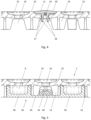
- Figure 4 is a cross-section through part of a tile 2, which shows how an insert 12 can be received and retained by one of the recesses 10.
- a hole 24 through to the underside of the tile 2.
- the shape of each insert 12 complements the shape of the recess 10.
- At the bottom of the insert is a pair of downwardly projecting arms 27, which engage the hole 24 in snap-fit connection.
- the arms 27 end in a pair of hooks 28 that face away from one another. In the relaxed state of the arms 27, the hooks 28 are too wide to fit through the hole 24 but the leading faces of the hooks 28 are tapered to guide them into the hole 24 and to urge the arms 27 to bend towards one another.
- the hooks 28 clear the bottom of the hole 24, allowing the arms 27 to spring resiliently apart. The hooks 28 then catch behind the bottom wall of the recess 10 to prevent the insert 12 being accidentally removed again.
- the arms 27 and the hole 24 may be configured so that it is possible to remove the inserts, for example using a special tool, or so that it is impossible to remove them without lifting the tile 2 to get access to the underside.
- the inserts 12 may be formed from the same material as the tile 2 or from a different material to provide different characteristics. They will generally be of one or more colours that are different from the tile 2 and it will readily be understood from Figure 1 how an arrangement of multiple inserts 12 over the array of recesses 10 can be used to build up a mosaic in any desired pattern.
- the inserts 12 are normally shaped so that their upper face 30 is flush with the upper surface 32 of the tile 2 but, as seen in Figure 4 , there may be circumstances in which a shallow domed profile is desirable, e.g. to provide increased grip on the floor surface.
- the upper face of at least some inserts could be textured for the same purpose.
- Some inserts could be shaped such that after insertion they create a fluid passage through the recess 10 - either through the body of the insert or around its outside - to provide drainage from the upper face of the tile 2. In many cases, it will be acceptable to leave some of the recesses 10 unfilled by inserts 12 so that the holes 24 provide drainage from the upper face of the tile and air circulation to the substrate below the tile.
- FIG. 2 this illustrates how a cable 34 may be ducted under the tile 2 through the channels 18 formed by rows or columns of cells 8 interconnected by arches 14.
- This is a convenient way to deliver electric power, networking or telecommunications services to apparatus that may be provided on the floor or on adjacent walls; or simply as a way for the cable 34 to cross the floor without creating a trip hazard.
- the cable 34 can be held in place by a removable clip 36, which bridges across the channel 18 in which the cable 34 has been laid.
- Each end of the clip 36 comprises a foot 38, which is shaped to be a push-fit into the adjacent hollow cell 8 on each side of the channel 18.
- Figure 5 is a partial cross-section showing the same arrangement, in which a cable is held in a channel 18 by a clip 36 that is anchored in adjacent cells 8 on each side.
- the cable in Figure 5 is a particular instance, namely a lighting cable 40, which has lighting elements 42 such as LEDs spaced at intervals along its length.
- the lighting elements 42 are spaced at intervals that are a multiple of the spacing between cells 8 of the grid, whereby it can be arranged that successive lighting elements 42 are aligned with recesses 10.
- Those recesses 10 can be left open or filled with translucent inserts 12 - either clear or coloured - to allow light from the lighting elements 42 to reach the upper surface 32 of the tile for decorative and/or practical purposes.
- the floor surface itself may be made sufficiently thin above some or all of the cells 8 that it becomes translucent to light emitted by a lighting cable 40 below the tile.
- Figure 6 illustrates another type of cable that may be ducted beneath a tile 2 according to the invention, namely a heating cable 44.
- the cable 44 carries electrically resistive heating elements (not shown), either continuously or at intervals along its length, from which heat can be conducted through the tile to warm the surface of the floor. Arranging the cable 44 in the serpentine manner shown ensures that the heat is evenly distributed across the area of the tile 2. Cable clips 36 (not shown in Figure 6 ) could again be used to secure the heating cable in position.
- FIGS 7 and 8 show an example of how the tiling system can be made to provide still more flexible designs by combining cut tile parts of different colours.
- the tile parts 50,52 may be parts of plain tiles 3 or of normal tiles 2 that have recesses 10.
- a single tile is replaced by two complementary parts 50,52 of tiles according to the invention, which have been cut along a curved line 54.
- the two parts 50,52 are secured together by a series of junction clips 56, which bridge the cut line 54.
- the junction clips 56 are very similar to the cable clips 36, having a foot 58 at each end that is a push-fit into a cell 8 on the underside of the respective tile part 50,52.
- junction clip 56 preferably bridges across two intermediate cells 8 to allow room for an oblique cut line 54 that crosses two cells (as seen near the bottom of Figure 7 ).
- the tile parts 50,52 form the same overall shape as a whole tile 2,3 and they can be used in the same manner as a whole tile when assembling a floor.
Landscapes
- Engineering & Computer Science (AREA)
- Architecture (AREA)
- Civil Engineering (AREA)
- Structural Engineering (AREA)
- Physics & Mathematics (AREA)
- Thermal Sciences (AREA)
- Chemical & Material Sciences (AREA)
- Combustion & Propulsion (AREA)
- Mechanical Engineering (AREA)
- General Engineering & Computer Science (AREA)
- Electromagnetism (AREA)
- Floor Finish (AREA)
- Finishing Walls (AREA)
Claims (15)
- Fliesensystem, umfassend:
mindestens eine Fliese (2,3), die eine obere Fläche, eine Unterseite und eine Vielzahl von Seitenkanten aufweist, wobei:die Unterseite der Fliese (2,3) eine Vielzahl von Zellen (8) umfasst, wobei benachbarte Zellen (8) miteinander verbunden sind, um eine Vielzahl von Kanälen (18,19) parallel zur oberen Fläche (32) zu bilden, wobei die Kanäle (18,19) nach unten offen sind und zumindest einige der Kanäle (18,19) in Öffnungen (20) an den Seitenkanten der Fliese (2,3) enden;die Kanäle einen ersten Satz von Kanälen (18) umfassen, die sich zwischen einem Paar gegenüberliegender Seitenkanten erstrecken, und einen zweiten Satz von Kanälen (19), die sich zwischen einem zweiten Paar gegenüberliegender Seitenkanten erstrecken; undmindestens eine der Seitenkanten Eingriffsmittel (22) umfasst, die zum Befestigen der Fliese (2,3) an einer benachbarten, ähnlichen Fliese geeignet sind;dadurch gekennzeichnet, dass jedes Eingriffsmittel (22) eine Biegung (23) umfasst, die sich von der Seitenkante der Fliese (2,3) erstreckt und in einem Vorsprung (21) endet, wobei sich die Biegung (23) in eine Öffnung (20) an einer Seitenkante der benachbarten Fliese erstreckt und der Vorsprung (21) in eine Zelle (8) an der Unterseite der benachbarten Fliese passt. - Fliesensystem nach Anspruch 1, wobei die Zellen (8) in einem Gittermuster angeordnet sind, wobei sich jede Zelle (8) am Schnittpunkt von einem des ersten Satzes von Kanälen (18) und von einem des zweiten Satzes von Kanälen (19) befindet.
- Fliesensystem nach Anspruch 1 oder Anspruch 2, das weiter einen Kabelclip (36) umfasst, der zwei Endabschnitte (38), die in entsprechende Zellen (8) an der Unterseite der Fliese (2,3) passen, und zwischen den beiden Endabschnitten (38) einen Brückenabschnitt (39) aufweist, der mindestens eine Zwischenzelle (8) überspannt, um ein Kabel (34) in einem der Kanäle (18,19) zu befestigen, das durch die Zwischenzelle (8) verläuft.
- Fliesensystem nach einem vorstehenden Anspruch, wobei die Fliese (2,3) zwei Fliesenteile (50,52) umfasst, die weiter einen Verbindungsclip (56) umfasst, der zwei Endabschnitte (58), die in jeweilige Zellen (8) an den Unterseiten der beiden Fliesenteile (50,52) passen, und zwischen den beiden Endabschnitten (58) einen Brückenabschnitt (59) aufweist, der eine Verbindungsstelle zwischen den beiden Fliesenteilen (50,52) überspannt, um die beiden Fliesenteile (50,52) zusammen zu befestigen.
- Fliesensystem nach einem vorstehenden Anspruch, das weiter ein Beleuchtungskabel (40) umfasst, das eine Vielzahl von Beleuchtungselementen (42) in Intervallen entlang des Beleuchtungskabels (40) trägt, wobei die Intervalle derart sind, dass, wenn sich das Beleuchtungskabel (40) in einem der Kanäle (18,19) an der Unterseite der Fliese (2,3) befindet, die Beleuchtungselemente (42) mit jeweiligen Zellen (8) der Fliese ausgerichtet sind.
- Fliesensystem nach einem vorstehenden Anspruch, wobei die Eingriffsmittel (22) in benachbarten Paaren vorliegen, wobei die Vorsprünge (21) der benachbarten Eingriffsmittel (22) miteinander verbunden sind.
- Fliesensystem nach Anspruch 6, wobei die Biegung (23) jedes Eingriffsmittels (22) S-förmig ist, wodurch sich die Biegung (23) in einer Ebene parallel zur oberen Fläche (32) der Fliese (2,3) biegen kann.
- Fliesensystem nach Anspruch 6 oder Anspruch 7, wobei der Vorsprung (21) jedes Eingriffsmittels (22) ein Schraubenloch (26) umfasst, durch das die Fliese (2,3) an einem Substrat befestigt werden kann.
- Fliesensystem nach einem vorstehenden Anspruch, das weiter eine Vielzahl von Einsätzen (12) umfasst;wobei die obere Fläche (32) der Fliese (2) eine Vielzahl von Aussparungen (10) umfasst; undwobei die Aussparungen (10) und die Einsätze (12) zusammenwirkende Mittel umfassen, durch welche die Einsätze (12) in den Aussparungen (10) gehalten werden.
- Fliesensystem nach Anspruch 9, wobei jede der Aussparungen (10) in der oberen Fläche (32) mit einer der Zellen (8) an der Unterseite der Fliese (2) ausgerichtet ist.
- Fliesensystem nach einem vorstehenden Anspruch, wobei die Zellen (8) an der Unterseite der Fliese (2,3) durch Bögen (14) getrennt sind, die ausgerichtet sind, um die Vielzahl von Kanälen (18,19) zu bilden, wodurch die Fliese (2,3) entlang einer Linie parallel zu einer ihrer Seitenkanten geschnitten werden kann, um eine ganze Zahl von Zellen (8) zu belassen, und um eine Linie der Bögen (14) freizulegen, die neue Endöffnungen (20) der Kanäle (18,19) bilden und imstande sind, Eingriffsmittel (22) einer benachbarten Fliese (2,3) aufzunehmen.
- Verfahren zum Zusammensetzen eines Fliesensystems, das mindestens eine Fliese (2,3) umfasst, die eine obere Fläche, eine Unterseite und eine Vielzahl von Seitenkanten aufweist, wobei:die Unterseite der Fliese (2,3) eine Vielzahl von Zellen (8) umfasst, wobei benachbarte Zellen (8) miteinander verbunden sind, um eine Vielzahl von Kanälen (18,19) parallel zur oberen Fläche (32) zu bilden;die Kanäle (18,19) zur Unterseite der Fliese (2,3) offen sind und zumindest einige der Kanäle (18,19) in Öffnungen (20) an den Seitenkanten der Fliese (2,3) enden;sich ein erster Satz der Kanäle (18) zwischen einem Paar gegenüberliegender Seitenkanten erstreckt;sich ein zweiter Satz von Kanälen (19) zwischen einem zweiten Paar gegenüberliegender Seitenkanten erstreckt; undmindestens eine der Seitenkanten Eingriffsmittel (22) umfasst, die eine Biegung (23) umfassen, die sich von der Seitenkante der Fliese (2,3) erstreckt und in einem Vorsprung (21) endet;wobei das Verfahren umfasst:
Anordnen eines Kabels (34) in einem oder mehreren der Kanäle (18,19); und Verlegen der Fliese (2,3) auf einem Substrat neben einer benachbarten, ähnlichen Fliese, so dass sich die Biegung (23) in eine Öffnung (20) an einer Seitenkante der benachbarten Fliese erstreckt, und der Vorsprung (21) in eine Zelle (8) an der Unterseite der benachbarten Fliese passt, um die Fliese (2,3) an der benachbarten Fliese zu befestigen. - Verfahren nach Anspruch 12, wobei das Kabel (34) ein Beleuchtungskabel (40) ist, das in Intervallen entlang des Beleuchtungskabels (40) eine Vielzahl von Beleuchtungselementen (42) trägt, wobei der Schritt des Anordnens des Kabels (34) in einem oder mehreren der Kanäle (18,19) das Ausrichten der Beleuchtungselemente (42) mit jeweiligen Zellen (8) der Fliese (2,3) umfasst.
- Verfahren nach Anspruch 12 oder Anspruch 13, das weiter das Anlegen der Enden (38) eines Kabelclips (36) an Zellen (8) an der Unterseite der Fliese (2,3) umfasst, um das Kabel (34) in dem Kanal (18,19) zu befestigen.
- Verfahren nach einem der Ansprüche 12 bis 14, wobei die obere Fläche (32) der Fliese (2) eine Vielzahl von Aussparungen (10) enthält, wobei das Verfahren den weiteren Schritt des Einpressens eine Vielzahl von Einsätzen (12) in die Aussparungen (10) umfasst, um in die Aussparungen (10) einzugreifen und von diesen gehalten zu werden.
Applications Claiming Priority (2)
| Application Number | Priority Date | Filing Date | Title |
|---|---|---|---|
| GB2000343.0A GB2590966B (en) | 2020-01-10 | 2020-01-10 | Mosaic tiles |
| PCT/EP2021/050307 WO2021140221A1 (en) | 2020-01-10 | 2021-01-08 | Tile systems and method of assembling a tile system |
Publications (3)
| Publication Number | Publication Date |
|---|---|
| EP4087976A1 EP4087976A1 (de) | 2022-11-16 |
| EP4087976B1 true EP4087976B1 (de) | 2024-03-13 |
| EP4087976C0 EP4087976C0 (de) | 2024-03-13 |
Family
ID=69626330
Family Applications (1)
| Application Number | Title | Priority Date | Filing Date |
|---|---|---|---|
| EP21700395.3A Active EP4087976B1 (de) | 2020-01-10 | 2021-01-08 | Fliesensystem und verfahren zum zusammenbau eines fliesensystems |
Country Status (5)
| Country | Link |
|---|---|
| US (1) | US12188229B2 (de) |
| EP (1) | EP4087976B1 (de) |
| ES (1) | ES2978488T3 (de) |
| GB (1) | GB2590966B (de) |
| WO (1) | WO2021140221A1 (de) |
Families Citing this family (8)
| Publication number | Priority date | Publication date | Assignee | Title |
|---|---|---|---|---|
| US11912247B2 (en) | 2019-10-10 | 2024-02-27 | Rubberform Recycled Products, Llc | Trackout mat |
| CN113957767B (zh) * | 2021-10-26 | 2022-10-18 | 江西向诚新材料有限公司 | 一种耐磨防滑跑道pu塑胶面层 |
| US12043966B2 (en) * | 2022-11-23 | 2024-07-23 | Light Penetrating Systems, LLC | Pedestal paver with transparent or translucent inserts |
| USD1065602S1 (en) | 2022-11-23 | 2025-03-04 | Light Penetrating Systems, LLC | Pedestal paver |
| US11891803B1 (en) * | 2023-01-12 | 2024-02-06 | Astra Capital Incorporated | Modular platform deck for traffic |
| GB2631759A (en) | 2023-07-13 | 2025-01-15 | Versoflor Ltd | Floor-mounted accessories |
| USD1067469S1 (en) | 2023-11-10 | 2025-03-18 | Light Penetrating Systems, LLC | Pedestal paver |
| WO2025186349A1 (de) * | 2024-03-05 | 2025-09-12 | PURUS PLASTICS GmbH | Kunststoff-mehrzwecksystem zur bewässerung und/oder entwässerung und dessen verwendung |
Family Cites Families (15)
| Publication number | Priority date | Publication date | Assignee | Title |
|---|---|---|---|---|
| NL8403764A (nl) * | 1984-12-12 | 1986-07-01 | Johannes Adriaanse | Wand- of plafondpaneel. |
| US5639531A (en) * | 1987-12-21 | 1997-06-17 | United Technologies Corporation | Process for making a hybrid ceramic article |
| US4930286A (en) * | 1988-03-14 | 1990-06-05 | Daniel Kotler | Modular sports tile with lateral absorption |
| KR100634178B1 (ko) * | 2004-12-28 | 2006-10-16 | 김유성 | 건축용 온돌판넬 및 그 시공방법 |
| US9010060B2 (en) * | 2007-05-09 | 2015-04-21 | Antonio Rapaz | Construction panel |
| KR101137235B1 (ko) * | 2011-10-26 | 2012-04-20 | 최광철 | 역 t자형 체결구조를 갖는 합성목재 데크 |
| AT511712B1 (de) * | 2012-01-11 | 2013-02-15 | Schlager Fensterbank Gmbh | Diele, insbesondere bodendiele sowie daraus gebildeter belag |
| KR101351442B1 (ko) * | 2013-08-09 | 2014-01-23 | 주식회사지이티-피씨 | 온돌블록 |
| US8756882B1 (en) * | 2013-10-31 | 2014-06-24 | Le Groupe Dsd Inc. | Tile for use in a modular flooring system |
| US9863155B2 (en) * | 2014-03-04 | 2018-01-09 | Connor Sport Court International, Llc | Synthetic flooring apparatus |
| GB2574337B (en) * | 2014-05-10 | 2020-02-19 | Epic Insulation Ltd | A liquid based heating or cooling assembly |
| FR3031999A1 (fr) * | 2015-01-23 | 2016-07-29 | Soc Loisirs Equipements | Lame de revetement antiderapante |
| KR101865706B1 (ko) * | 2017-09-21 | 2018-06-11 | 안창옥 | 발광형 보도블럭 |
| NL2019898B1 (en) * | 2017-11-13 | 2019-05-17 | Supersub Sportbases B V | Underlayment for dampening a top floor. |
| GB2569385A (en) * | 2017-12-18 | 2019-06-19 | Molesworth Richard | Non-slip surface assembly |
-
2020
- 2020-01-10 GB GB2000343.0A patent/GB2590966B/en active Active
-
2021
- 2021-01-08 EP EP21700395.3A patent/EP4087976B1/de active Active
- 2021-01-08 ES ES21700395T patent/ES2978488T3/es active Active
- 2021-01-08 WO PCT/EP2021/050307 patent/WO2021140221A1/en not_active Ceased
-
2022
- 2022-07-06 US US17/858,671 patent/US12188229B2/en active Active
Also Published As
| Publication number | Publication date |
|---|---|
| US12188229B2 (en) | 2025-01-07 |
| WO2021140221A1 (en) | 2021-07-15 |
| GB2590966A (en) | 2021-07-14 |
| GB202000343D0 (en) | 2020-02-26 |
| EP4087976A1 (de) | 2022-11-16 |
| GB2590966B (en) | 2022-09-14 |
| ES2978488T3 (es) | 2024-09-13 |
| EP4087976C0 (de) | 2024-03-13 |
| US20220341163A1 (en) | 2022-10-27 |
Similar Documents
| Publication | Publication Date | Title |
|---|---|---|
| EP4087976B1 (de) | Fliesensystem und verfahren zum zusammenbau eines fliesensystems | |
| CA2305405C (en) | Flooring system | |
| AU619102B2 (en) | Modular hollow floor panels with interlocking keys | |
| US6918215B2 (en) | Free floating sub-floor panel | |
| CA2924162C (en) | Tile for use in a modular flooring system | |
| AU2004279976B2 (en) | Constructional panels | |
| USRE35369E (en) | Flooring system especially designed for facilities which house data processing equipment | |
| EP0220259A1 (de) | Doppelbodenkonstruktion. | |
| WO2004111544A1 (en) | Indoor floor heating system | |
| JP6714594B2 (ja) | 床材モジュール | |
| WO2012158037A1 (en) | Assembly of tiles for forming a floor | |
| AU719828B2 (en) | Flooring system | |
| JP3144320U (ja) | 導管システム | |
| EP1309761B1 (de) | Bodenbelagsystem mit einem Bodenbelag und mit Unterbodenplatten | |
| CA1311899C (en) | Modular hollow floor panels with integral ducting | |
| AU2001276229A1 (en) | Free floating sub-floor panel | |
| JP2025104623A (ja) | デッキ及びその設置方法 | |
| WO2026061628A1 (en) | External floor/support element for snapping in decorative elements | |
| US10190322B2 (en) | Interlocking arch tile | |
| GB2566521A (en) | Tiling system | |
| HK1057587B (en) | Flooring system with floor layer and sub-floor panels | |
| HK1029152A1 (en) | Paving of concrete paving stones | |
| HK1029152B (en) | Paving of concrete paving stones | |
| HK1241950A1 (en) | Flooring module | |
| NZ238135A (en) | Modular floor ducting panel |
Legal Events
| Date | Code | Title | Description |
|---|---|---|---|
| STAA | Information on the status of an ep patent application or granted ep patent |
Free format text: STATUS: UNKNOWN |
|
| STAA | Information on the status of an ep patent application or granted ep patent |
Free format text: STATUS: THE INTERNATIONAL PUBLICATION HAS BEEN MADE |
|
| PUAI | Public reference made under article 153(3) epc to a published international application that has entered the european phase |
Free format text: ORIGINAL CODE: 0009012 |
|
| STAA | Information on the status of an ep patent application or granted ep patent |
Free format text: STATUS: REQUEST FOR EXAMINATION WAS MADE |
|
| 17P | Request for examination filed |
Effective date: 20220805 |
|
| AK | Designated contracting states |
Kind code of ref document: A1 Designated state(s): AL AT BE BG CH CY CZ DE DK EE ES FI FR GB GR HR HU IE IS IT LI LT LU LV MC MK MT NL NO PL PT RO RS SE SI SK SM TR |
|
| DAV | Request for validation of the european patent (deleted) | ||
| DAX | Request for extension of the european patent (deleted) | ||
| GRAP | Despatch of communication of intention to grant a patent |
Free format text: ORIGINAL CODE: EPIDOSNIGR1 |
|
| STAA | Information on the status of an ep patent application or granted ep patent |
Free format text: STATUS: GRANT OF PATENT IS INTENDED |
|
| INTG | Intention to grant announced |
Effective date: 20231005 |
|
| GRAS | Grant fee paid |
Free format text: ORIGINAL CODE: EPIDOSNIGR3 |
|
| GRAA | (expected) grant |
Free format text: ORIGINAL CODE: 0009210 |
|
| STAA | Information on the status of an ep patent application or granted ep patent |
Free format text: STATUS: THE PATENT HAS BEEN GRANTED |
|
| RIN1 | Information on inventor provided before grant (corrected) |
Inventor name: PARSONS, DARREN |
|
| AK | Designated contracting states |
Kind code of ref document: B1 Designated state(s): AL AT BE BG CH CY CZ DE DK EE ES FI FR GB GR HR HU IE IS IT LI LT LU LV MC MK MT NL NO PL PT RO RS SE SI SK SM TR |
|
| REG | Reference to a national code |
Ref country code: GB Ref legal event code: FG4D |
|
| REG | Reference to a national code |
Ref country code: CH Ref legal event code: EP |
|
| REG | Reference to a national code |
Ref country code: DE Ref legal event code: R096 Ref document number: 602021010383 Country of ref document: DE |
|
| REG | Reference to a national code |
Ref country code: IE Ref legal event code: FG4D |
|
| U01 | Request for unitary effect filed |
Effective date: 20240411 |
|
| U07 | Unitary effect registered |
Designated state(s): AT BE BG DE DK EE FI FR IT LT LU LV MT NL PT SE SI Effective date: 20240418 |
|
| PG25 | Lapsed in a contracting state [announced via postgrant information from national office to epo] |
Ref country code: GR Free format text: LAPSE BECAUSE OF FAILURE TO SUBMIT A TRANSLATION OF THE DESCRIPTION OR TO PAY THE FEE WITHIN THE PRESCRIBED TIME-LIMIT Effective date: 20240614 |
|
| PG25 | Lapsed in a contracting state [announced via postgrant information from national office to epo] |
Ref country code: RS Free format text: LAPSE BECAUSE OF FAILURE TO SUBMIT A TRANSLATION OF THE DESCRIPTION OR TO PAY THE FEE WITHIN THE PRESCRIBED TIME-LIMIT Effective date: 20240613 Ref country code: HR Free format text: LAPSE BECAUSE OF FAILURE TO SUBMIT A TRANSLATION OF THE DESCRIPTION OR TO PAY THE FEE WITHIN THE PRESCRIBED TIME-LIMIT Effective date: 20240313 |
|
| PG25 | Lapsed in a contracting state [announced via postgrant information from national office to epo] |
Ref country code: RS Free format text: LAPSE BECAUSE OF FAILURE TO SUBMIT A TRANSLATION OF THE DESCRIPTION OR TO PAY THE FEE WITHIN THE PRESCRIBED TIME-LIMIT Effective date: 20240613 Ref country code: NO Free format text: LAPSE BECAUSE OF FAILURE TO SUBMIT A TRANSLATION OF THE DESCRIPTION OR TO PAY THE FEE WITHIN THE PRESCRIBED TIME-LIMIT Effective date: 20240613 Ref country code: HR Free format text: LAPSE BECAUSE OF FAILURE TO SUBMIT A TRANSLATION OF THE DESCRIPTION OR TO PAY THE FEE WITHIN THE PRESCRIBED TIME-LIMIT Effective date: 20240313 Ref country code: GR Free format text: LAPSE BECAUSE OF FAILURE TO SUBMIT A TRANSLATION OF THE DESCRIPTION OR TO PAY THE FEE WITHIN THE PRESCRIBED TIME-LIMIT Effective date: 20240614 |
|
| REG | Reference to a national code |
Ref country code: ES Ref legal event code: FG2A Ref document number: 2978488 Country of ref document: ES Kind code of ref document: T3 Effective date: 20240913 |
|
| PG25 | Lapsed in a contracting state [announced via postgrant information from national office to epo] |
Ref country code: IS Free format text: LAPSE BECAUSE OF FAILURE TO SUBMIT A TRANSLATION OF THE DESCRIPTION OR TO PAY THE FEE WITHIN THE PRESCRIBED TIME-LIMIT Effective date: 20240713 |
|
| PG25 | Lapsed in a contracting state [announced via postgrant information from national office to epo] |
Ref country code: SM Free format text: LAPSE BECAUSE OF FAILURE TO SUBMIT A TRANSLATION OF THE DESCRIPTION OR TO PAY THE FEE WITHIN THE PRESCRIBED TIME-LIMIT Effective date: 20240313 |
|
| PG25 | Lapsed in a contracting state [announced via postgrant information from national office to epo] |
Ref country code: CZ Free format text: LAPSE BECAUSE OF FAILURE TO SUBMIT A TRANSLATION OF THE DESCRIPTION OR TO PAY THE FEE WITHIN THE PRESCRIBED TIME-LIMIT Effective date: 20240313 |
|
| PG25 | Lapsed in a contracting state [announced via postgrant information from national office to epo] |
Ref country code: PL Free format text: LAPSE BECAUSE OF FAILURE TO SUBMIT A TRANSLATION OF THE DESCRIPTION OR TO PAY THE FEE WITHIN THE PRESCRIBED TIME-LIMIT Effective date: 20240313 |
|
| PG25 | Lapsed in a contracting state [announced via postgrant information from national office to epo] |
Ref country code: SK Free format text: LAPSE BECAUSE OF FAILURE TO SUBMIT A TRANSLATION OF THE DESCRIPTION OR TO PAY THE FEE WITHIN THE PRESCRIBED TIME-LIMIT Effective date: 20240313 |
|
| PG25 | Lapsed in a contracting state [announced via postgrant information from national office to epo] |
Ref country code: SM Free format text: LAPSE BECAUSE OF FAILURE TO SUBMIT A TRANSLATION OF THE DESCRIPTION OR TO PAY THE FEE WITHIN THE PRESCRIBED TIME-LIMIT Effective date: 20240313 Ref country code: SK Free format text: LAPSE BECAUSE OF FAILURE TO SUBMIT A TRANSLATION OF THE DESCRIPTION OR TO PAY THE FEE WITHIN THE PRESCRIBED TIME-LIMIT Effective date: 20240313 Ref country code: RO Free format text: LAPSE BECAUSE OF FAILURE TO SUBMIT A TRANSLATION OF THE DESCRIPTION OR TO PAY THE FEE WITHIN THE PRESCRIBED TIME-LIMIT Effective date: 20240313 Ref country code: PL Free format text: LAPSE BECAUSE OF FAILURE TO SUBMIT A TRANSLATION OF THE DESCRIPTION OR TO PAY THE FEE WITHIN THE PRESCRIBED TIME-LIMIT Effective date: 20240313 Ref country code: IS Free format text: LAPSE BECAUSE OF FAILURE TO SUBMIT A TRANSLATION OF THE DESCRIPTION OR TO PAY THE FEE WITHIN THE PRESCRIBED TIME-LIMIT Effective date: 20240713 Ref country code: CZ Free format text: LAPSE BECAUSE OF FAILURE TO SUBMIT A TRANSLATION OF THE DESCRIPTION OR TO PAY THE FEE WITHIN THE PRESCRIBED TIME-LIMIT Effective date: 20240313 |
|
| REG | Reference to a national code |
Ref country code: DE Ref legal event code: R097 Ref document number: 602021010383 Country of ref document: DE |
|
| U20 | Renewal fee for the european patent with unitary effect paid |
Year of fee payment: 5 Effective date: 20241202 |
|
| PLBE | No opposition filed within time limit |
Free format text: ORIGINAL CODE: 0009261 |
|
| STAA | Information on the status of an ep patent application or granted ep patent |
Free format text: STATUS: NO OPPOSITION FILED WITHIN TIME LIMIT |
|
| 26N | No opposition filed |
Effective date: 20241216 |
|
| PGFP | Annual fee paid to national office [announced via postgrant information from national office to epo] |
Ref country code: ES Payment date: 20250203 Year of fee payment: 5 |
|
| PGFP | Annual fee paid to national office [announced via postgrant information from national office to epo] |
Ref country code: IE Payment date: 20250116 Year of fee payment: 5 |
|
| PGFP | Annual fee paid to national office [announced via postgrant information from national office to epo] |
Ref country code: CH Payment date: 20250201 Year of fee payment: 5 |
|
| PG25 | Lapsed in a contracting state [announced via postgrant information from national office to epo] |
Ref country code: MC Free format text: LAPSE BECAUSE OF FAILURE TO SUBMIT A TRANSLATION OF THE DESCRIPTION OR TO PAY THE FEE WITHIN THE PRESCRIBED TIME-LIMIT Effective date: 20240313 |
|
| U20 | Renewal fee for the european patent with unitary effect paid |
Year of fee payment: 6 Effective date: 20251117 |
|
| PGFP | Annual fee paid to national office [announced via postgrant information from national office to epo] |
Ref country code: GB Payment date: 20251117 Year of fee payment: 6 |
|
| REG | Reference to a national code |
Ref country code: CH Ref legal event code: U11 Free format text: ST27 STATUS EVENT CODE: U-0-0-U10-U11 (AS PROVIDED BY THE NATIONAL OFFICE) Effective date: 20260201 |