EP4086998A1 - Compounding device and lamination machine - Google Patents
Compounding device and lamination machine Download PDFInfo
- Publication number
- EP4086998A1 EP4086998A1 EP21920114.2A EP21920114A EP4086998A1 EP 4086998 A1 EP4086998 A1 EP 4086998A1 EP 21920114 A EP21920114 A EP 21920114A EP 4086998 A1 EP4086998 A1 EP 4086998A1
- Authority
- EP
- European Patent Office
- Prior art keywords
- material strip
- composite
- sheet
- diaphragm
- sheet material
- Prior art date
- Legal status (The legal status is an assumption and is not a legal conclusion. Google has not performed a legal analysis and makes no representation as to the accuracy of the status listed.)
- Granted
Links
Images



Classifications
-
- H—ELECTRICITY
- H01—ELECTRIC ELEMENTS
- H01M—PROCESSES OR MEANS, e.g. BATTERIES, FOR THE DIRECT CONVERSION OF CHEMICAL ENERGY INTO ELECTRICAL ENERGY
- H01M10/00—Secondary cells; Manufacture thereof
- H01M10/04—Construction or manufacture in general
- H01M10/0404—Machines for assembling batteries
-
- B—PERFORMING OPERATIONS; TRANSPORTING
- B23—MACHINE TOOLS; METAL-WORKING NOT OTHERWISE PROVIDED FOR
- B23K—SOLDERING OR UNSOLDERING; WELDING; CLADDING OR PLATING BY SOLDERING OR WELDING; CUTTING BY APPLYING HEAT LOCALLY, e.g. FLAME CUTTING; WORKING BY LASER BEAM
- B23K26/00—Working by laser beam, e.g. welding, cutting or boring
- B23K26/36—Removing material
- B23K26/38—Removing material by boring or cutting
-
- B—PERFORMING OPERATIONS; TRANSPORTING
- B65—CONVEYING; PACKING; STORING; HANDLING THIN OR FILAMENTARY MATERIAL
- B65H—HANDLING THIN OR FILAMENTARY MATERIAL, e.g. SHEETS, WEBS, CABLES
- B65H35/00—Delivering articles from cutting or line-perforating machines; Article or web delivery apparatus incorporating cutting or line-perforating devices, e.g. adhesive tape dispensers
- B65H35/0006—Article or web delivery apparatus incorporating cutting or line-perforating devices
- B65H35/0073—Details
- B65H35/008—Arrangements or adaptations of cutting devices
-
- B—PERFORMING OPERATIONS; TRANSPORTING
- B65—CONVEYING; PACKING; STORING; HANDLING THIN OR FILAMENTARY MATERIAL
- B65H—HANDLING THIN OR FILAMENTARY MATERIAL, e.g. SHEETS, WEBS, CABLES
- B65H35/00—Delivering articles from cutting or line-perforating machines; Article or web delivery apparatus incorporating cutting or line-perforating devices, e.g. adhesive tape dispensers
- B65H35/04—Delivering articles from cutting or line-perforating machines; Article or web delivery apparatus incorporating cutting or line-perforating devices, e.g. adhesive tape dispensers from or with transverse cutters or perforators
-
- H—ELECTRICITY
- H01—ELECTRIC ELEMENTS
- H01M—PROCESSES OR MEANS, e.g. BATTERIES, FOR THE DIRECT CONVERSION OF CHEMICAL ENERGY INTO ELECTRICAL ENERGY
- H01M10/00—Secondary cells; Manufacture thereof
- H01M10/04—Construction or manufacture in general
- H01M10/0431—Cells with wound or folded electrodes
-
- H—ELECTRICITY
- H01—ELECTRIC ELEMENTS
- H01M—PROCESSES OR MEANS, e.g. BATTERIES, FOR THE DIRECT CONVERSION OF CHEMICAL ENERGY INTO ELECTRICAL ENERGY
- H01M10/00—Secondary cells; Manufacture thereof
- H01M10/05—Accumulators with non-aqueous electrolyte
- H01M10/058—Construction or manufacture
- H01M10/0583—Construction or manufacture of accumulators with folded construction elements except wound ones, i.e. folded positive or negative electrodes or separators, e.g. with "Z"-shaped electrodes or separators
-
- B—PERFORMING OPERATIONS; TRANSPORTING
- B65—CONVEYING; PACKING; STORING; HANDLING THIN OR FILAMENTARY MATERIAL
- B65H—HANDLING THIN OR FILAMENTARY MATERIAL, e.g. SHEETS, WEBS, CABLES
- B65H2301/00—Handling processes for sheets or webs
- B65H2301/50—Auxiliary process performed during handling process
- B65H2301/51—Modifying a characteristic of handled material
- B65H2301/515—Cutting handled material
- B65H2301/5152—Cutting partially, e.g. perforating
-
- B—PERFORMING OPERATIONS; TRANSPORTING
- B65—CONVEYING; PACKING; STORING; HANDLING THIN OR FILAMENTARY MATERIAL
- B65H—HANDLING THIN OR FILAMENTARY MATERIAL, e.g. SHEETS, WEBS, CABLES
- B65H2301/00—Handling processes for sheets or webs
- B65H2301/50—Auxiliary process performed during handling process
- B65H2301/51—Modifying a characteristic of handled material
- B65H2301/515—Cutting handled material
- B65H2301/5153—Details of cutting means
- B65H2301/51536—Laser
-
- B—PERFORMING OPERATIONS; TRANSPORTING
- B65—CONVEYING; PACKING; STORING; HANDLING THIN OR FILAMENTARY MATERIAL
- B65H—HANDLING THIN OR FILAMENTARY MATERIAL, e.g. SHEETS, WEBS, CABLES
- B65H2701/00—Handled material; Storage means
- B65H2701/10—Handled articles or webs
- B65H2701/19—Specific article or web
-
- B—PERFORMING OPERATIONS; TRANSPORTING
- B65—CONVEYING; PACKING; STORING; HANDLING THIN OR FILAMENTARY MATERIAL
- B65H—HANDLING THIN OR FILAMENTARY MATERIAL, e.g. SHEETS, WEBS, CABLES
- B65H2801/00—Application field
- B65H2801/72—Fuel cell manufacture
-
- Y—GENERAL TAGGING OF NEW TECHNOLOGICAL DEVELOPMENTS; GENERAL TAGGING OF CROSS-SECTIONAL TECHNOLOGIES SPANNING OVER SEVERAL SECTIONS OF THE IPC; TECHNICAL SUBJECTS COVERED BY FORMER USPC CROSS-REFERENCE ART COLLECTIONS [XRACs] AND DIGESTS
- Y02—TECHNOLOGIES OR APPLICATIONS FOR MITIGATION OR ADAPTATION AGAINST CLIMATE CHANGE
- Y02E—REDUCTION OF GREENHOUSE GAS [GHG] EMISSIONS, RELATED TO ENERGY GENERATION, TRANSMISSION OR DISTRIBUTION
- Y02E60/00—Enabling technologies; Technologies with a potential or indirect contribution to GHG emissions mitigation
- Y02E60/10—Energy storage using batteries
-
- Y—GENERAL TAGGING OF NEW TECHNOLOGICAL DEVELOPMENTS; GENERAL TAGGING OF CROSS-SECTIONAL TECHNOLOGIES SPANNING OVER SEVERAL SECTIONS OF THE IPC; TECHNICAL SUBJECTS COVERED BY FORMER USPC CROSS-REFERENCE ART COLLECTIONS [XRACs] AND DIGESTS
- Y02—TECHNOLOGIES OR APPLICATIONS FOR MITIGATION OR ADAPTATION AGAINST CLIMATE CHANGE
- Y02P—CLIMATE CHANGE MITIGATION TECHNOLOGIES IN THE PRODUCTION OR PROCESSING OF GOODS
- Y02P70/00—Climate change mitigation technologies in the production process for final industrial or consumer products
- Y02P70/50—Manufacturing or production processes characterised by the final manufactured product
Definitions
- the present application relates to a technical field of lithium battery manufacturing, and more specifically, to a composite device and a laminating machine.
- a manufacturing process of a lithium battery includes a step of laminating.
- belt-shaped pole sheets are usually cut to form sheet materials, and the sheet materials are attached to diaphragms to form a composite material strip, and then the composite material strip is folded by a laminating device to complete the laminating step.
- the belt-shaped pole sheets need to be cut to form sheet materials with same size, and then the sheet materials are attached to the diaphragms, and finally folded by the laminating device, efficiency is low.
- a composite device including:
- the crease mechanism forms the plurality of creases on the first electrode material strip, and the first diaphragm and the second diaphragm are attached to opposite sides of the first electrode material strip to form the first composite material strip.
- the first composite material strip may be directly folded along the creases.
- the composite device uses belt-shaped pole sheets directly without cutting, which effectively improves an efficiency of subsequent lamination. Meanwhile, more burrs may be prevented from cutting the pole sheets, so that quality of batteries is improved.
- the composite device further includes a first diaphragm unwinding mechanism and a second diaphragm unwinding mechanism, and the first diaphragm unwinding mechanism and the second diaphragm unwinding mechanism are both disposed upstream of the first composite mechanism; the first diaphragm unwinding mechanism is configured to unwind the first diaphragm, and the second diaphragm unwinding mechanism is configured to unwind the second diaphragm.
- the crease mechanism includes a laser cutting head or a cutter.
- the creases are penetrating holes sequentially spaced apart along a width direction of the first electrode material strip and penetrating the first electrode material strip along a thickness direction of the first electrode material strip.
- the penetrating holes include one or more of circular holes, rectangular holes or strip holes.
- the creases are folded areas extending longitudinally along a width direction of the first electrode material strip, and a thickness of the folded areas of the first electrode material strip is less than a thickness of other positions of the first electrode material strip.
- a folded sheet is formed between two adjacent creases on the first electrode material strip
- the second composite material strip includes a plurality of first stacking components and a plurality of second stacking components, and the first stacking components and the second stacking components are alternately connected;
- the first stacking components include the first sheet material, the first diaphragm, the folded sheet, and the second diaphragm that are stacked in sequence
- the second stacking components include the second sheet material, the second diaphragm, the folded sheet, and the first diaphragm that are stacked in sequence;
- the laminating machine further includes a first laminating device, the first laminating device is disposed downstream of the second composite mechanism and is configured to perform folding on the second composite material strip along the creases, so that a battery cell is formed by alternately stacking the plurality of first stacking components and the plurality of second stacking components.
- a folded sheet is formed between two adjacent creases on the first electrode material strip
- the third composite material strip includes a plurality of third stacking components and a plurality of fourth stacking components, and the third stacking components and the fourth stacking components are alternately connected;
- the third stacking components include the first sheet material, the first diaphragm, the folded sheet, the second diaphragm, and the second sheet material that are stacked in sequence, and the fourth stacking components include the first diaphragm, the folded sheet, and the second diaphragm that are stacked in sequence;
- the laminating machine further includes a third laminating device, and the third laminating device is disposed downstream of the second composite mechanism and is configured to fold the third composite material strip along the creases, so that the plurality of third stacking components and the plurality of fourth stacking components are alternately stacked to form a battery cell.
- a folded sheet is formed between two adjacent creases on the first electrode material strip; the laminating machine further includes a fourth laminating device, and the fourth laminating device is disposed downstream of the first composite mechanism and is configured to fold the first composite material strip along the creases, and during a folding process, a third sheet material is placed on the first diaphragm and the second diaphragm in sequence, so that the first diaphragm, the folded sheet, the second diaphragm, and the third sheet material are sequentially stacked to form a battery cell.
- first and second are used herein for purposes of description and are intended to indicate or imply relative importance or significance or to imply the number of indicated technical features.
- the feature defined with “first”, “second” may explicitly or implicitly include at least one of the features.
- “multiple” means at least two, such as two, three, etc., unless clearly specified otherwise.
- a structure in which a first feature is “on” or “below” a second feature may include an embodiment in which the first feature in direct contact with the second feature, and may also include an embodiment in which the first feature and the second feature are not in direct contact with each other, but are contacted via an additional feature formed therebetween.
- a first feature "on”, “above” and “on top of” a second feature may include an embodiment in which the first feature is right or obliquely “on”, “above” or “on top of” the second feature, or simply means that the first feature is at a height higher than that of the second feature.
- first feature "below”, “under” or “on bottom of” a second feature may include an embodiment in which the first feature is right or obliquely “below”, “under” or “on bottom of” the second feature, or simply means that the first feature is at a height lower than that of the second feature.
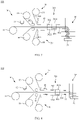
- a composite device 10 provided by an embodiment of the present application includes a first electrode material strip unwinding mechanism 11, a crease mechanism 12, and a first composite mechanism 13.
- the first electrode material strip unwinding mechanism 11 is configured to unwind a first electrode material strip 201
- the crease mechanism 12 is disposed downstream of the first electrode material strip unwinding mechanism 11
- the first composite mechanism 13 is disposed downstream of the crease mechanism 12.
- the crease mechanism 12 is configured to form a plurality of creases spaced apart along a length direction of a first electrode material strip 201 and extending along a width direction on the first electrode material strip 201, and the first composite mechanism 13 is configured to combine a first diaphragm 202 and a second diaphragm 203 on opposite sides of the first electrode material strip 201 to form a first composite material strip 200.
- the first electrode material strip 201 is a belt-shaped pole sheet.
- the crease mechanism 12 forms the plurality of creases on the first electrode material strip 201, and the first diaphragm 202 and the second diaphragm 203 are attached to two sides of the first electrode material strip 201 to form the first composite material strip 200.
- the first composite material strip 200 it may be directly folded along the creases.
- the composite device 10 uses belt-shaped pole sheets directly without cutting, which effectively improves efficiency of subsequent lamination. Meanwhile, more burrs may be prevented from cutting the pole sheets, so that quality of batteries is improved.
- the composite device 10 is configured to form the first composite material strip 200.
- the first electrode material strip 201 of the first composite material strip 200 has the plurality of creases, so as to facilitate subsequent folding.
- a pole sheet may be laid on the first composite material strip 200 and then folded to form a battery cell according to an actual process, which will not be repeated in this embodiment.
- hardness of the pole sheet is greater than hardness of the first diaphragm 202 and the second diaphragm 203.
- An existing laminating method is to fold the pole sheet in view of a sheet material, whereas in this embodiment, it is convenient to fold the belt-shaped pole sheet, so the creases are formed on the first electrode material strip 201, namely, the belt-shaped pole sheet.
- the composite device 10 further includes a first diaphragm unwinding mechanism 14.
- the first diaphragm unwinding mechanism 14 is disposed upstream of a composite mechanism and is configured to unwind the first diaphragm 202.
- the composite device 10 further includes a second diaphragm unwinding mechanism 15.
- the second diaphragm unwinding mechanism 15 is disposed upstream of the composite mechanism and is configured to unwind the second diaphragm 203.
- the crease mechanism 12 includes a laser cutting head or a cutter, the laser cutting head or the cutter is configured to form the creases on the belt-shaped pole sheet along a width direction thereof, and the plurality of creases are evenly spaced apart along a length direction thereof.
- the creases on the belt-shaped pole sheet may be formed by penetrating holes opened on the pole sheet by using the laser cutting head or the cutter, and the penetrating holes are sequentially spaced apart along a width direction of the first electrode material strip 201 and penetrates the first electrode material strip 201 along a thickness direction thereof.
- the penetrating holes include one or more of circular holes, rectangular holes, and strip holes.
- the creases may also be folded areas extending longitudinally along the width direction of the first electrode material strip 201, and a part of carbon powder in a dotted area is removed by laser, so that a carbon powder layer in this area is less than the carbon powder layer in other positions. That is, a thickness of the folded areas of the first electrode material strip 201 is less than a thickness of other positions of the first electrode material strip 201, resulting in weakening of strength of the areas, which facilitates folding.
- surfaces of opposite sides of the first diaphragm 202 and the second diaphragm 203 are provided with adhesives.
- the adhesives are melted, and the first diaphragm 202 and the second diaphragm 203 are bonded together with the belt-shaped pole sheet to form the first composite material strip 200.
- side surfaces of the first diaphragm 202 and the second diaphragm 203 facing away from the belt-shaped pole sheet are also secured with adhesion by adhesives.
- the present application also provides a laminating machine, which includes the above-mentioned composite device 10, wherein after the crease mechanism 12 of the above-mentioned composite device 10 forms the plurality of creases on the first electrode material strip 201, a folded sheet is formed between two adjacent creases on the first electrode material strip 201.
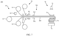
- the laminating machine 100 further includes a first sheet material device 20 and a second sheet material device 30.
- the first sheet material device 20 is configured to dispose a plurality of first sheet materials 301 on a side surface of the first composite material strip 200
- the second sheet material device 30 is configured to dispose a plurality of second sheet materials 302 on another side surface of the first composite material strip 200; and the first sheet materials 301 and the second sheet materials 302 are alternately spaced apart along a length direction of the first composite material strip 200, and two adjacent first sheet materials 301 and the second sheet materials 302 along the length direction of the first composite material strip 200 correspond to two adjacent folded sheets, respectively.
- first sheet material 301 and the second sheet material 302 are both pole sheets.
- a battery cell in which the first sheet material 301, the first composite material strip 200, the second sheet material 302, and the first composite material strip 200 are stacked in sequence may be formed.
- the creases are formed on the belt-shaped pole sheet in advance, which facilitates folding and improves folding efficiency.
- the first sheet material 301 and the second sheet material 302 are both positive pole sheets.
- the first sheet material 301 and the second sheet material 302 are both negative pole sheets.
- the first diaphragm 202 and the second diaphragm 203 may be same.
- the first sheet material device 20 is configured to dispose a plurality of first sheet materials 301 on a side surface of the first diaphragm 202 facing away from the first electrode material strip 201
- the second sheet material device 30 is configured to dispose a plurality of second sheet materials 302 on a side surface of the second diaphragm 203 facing away from the first electrode material strip 201.
- the battery cell when folded, the battery cell is formed by sequentially stacking the first sheet material 301, the first diaphragm 202, the folded sheet, the second diaphragm 203, the second sheet material 302, the second diaphragm 203, the folded sheet, and the first diaphragm 202 in a predetermined number.
- the first sheet material 301 (the second sheet material 302) is a pole sheet and is one of the positive electrode and the negative electrode
- the first electrode material strip 201 is another of the positive electrode and the negative electrode.
- a battery cell will be formed by sequentially and cyclically stacking a diaphragm, a positive pole sheet, a diaphragm, and a negative pole sheet.
- the plurality of creases on the first electrode material strip 201 are evenly spaced apart along a length direction of the first electrode material strip 201, and each first sheet material 301 and each second sheet material 302 corresponds to the folded sheet, so all the first sheet materials 301 and all the second sheet materials 302 are evenly spaced apart along the length direction of the first electrode material strip 201, namely, along the length direction of the first composite material strip 200.
- a distance between two adjacent first sheet materials 301 along the length direction of the first composite material strip 200 is greater than a width of the second sheet materials 302, and a distance between two adjacent second sheet materials 302 along the length direction of the first composite material strip 200 is greater than a width of the first sheet materials 301.
- width directions of the first sheet material 301 and the second sheet material 302 are the length direction of the first composite material strip 200.
- the first sheet material device 20 includes a second electrode material strip unwinding mechanism 21 and a first cutting mechanism 22.
- the second electrode material strip unwinding mechanism 21 is configured to unwind a second electrode material strip 400.
- the first cutting mechanism 22 is disposed downstream of the second electrode material strip unwinding mechanism 21, and the first cutting mechanism 22 is configured to cut the second electrode material strip 400 to form the first sheet material 301.
- the second sheet material device 30 includes a third electrode material strip unwinding mechanism 31 and a second cutting mechanism 32.
- the third electrode material strip unwinding mechanism 31 is configured to unwind a third electrode material strip 500.
- the second cutting mechanism 32 is disposed downstream of the third electrode material strip unwinding mechanism 31, and the second cutting mechanism 32 is configured to cut the third electrode material strip 500 to form the second sheet material 302.
- the above-mentioned second electrode material strip 400 and third electrode material strip 500 are same as the first electrode material strip 201, and they are all belt-shaped pole sheets.
- the first sheet material 301 and the second sheet material 302 may be initially attached to the first diaphragm 202 and the second diaphragm 203, respectively.
- the first sheet material 301 and the second sheet material 302 may be initially attached to the first diaphragm 202 and the second diaphragm 203 respectively by additionally disposing other mechanisms, which is not limited here.
- the laminating machine further includes a second composite mechanism 40.
- the second composite mechanism 40 is disposed downstream of the first sheet material device 20 and the second sheet material device 30 and is configured to combine the first sheet material 301 and the second sheet material 302 with the first composite material strip 200, so that the first sheet material 301 and the second sheet material 302 are attached to the first composite material strip 200 to form a second composite material strip 303.
- the second composite material strip 303 includes a plurality of first stacking components 3031 and a plurality of second stacking components 3032, and the first stacking components 3031 and the second stacking components 3032 are alternately connected.
- the first stacking components 3031 include the first sheet material 301, the first diaphragm 202, the folded sheet, and the second diaphragm 203 stacked in sequence
- the second stacking components 3032 include the first diaphragm 202, the folded sheet, the second diaphragm 203, and the second sheet material 302 stacked in sequence.
- the laminating machine further includes a first laminating device 50, and the first laminating device 50 is disposed downstream of the second composite mechanism 40 and is configured to perform folding on the second composite material strip 303 along the creases, so that the above-mentioned battery cell is formed by alternately stacking the plurality of first stacking components 3031 and the plurality of second stacking components 3032.
- the first laminating device 50 includes a laminating platform 51, and the second composite material strip 303 is conveyed from top to bottom in a vertical direction and is folded on the laminating platform 51.
- folding of the second composite material strip 303 may be realized by using an air blowing structure or a material pushing bracket in conjunction with gravity. Alternatively, the folding of the second composite material strip 303 may be realized by gravity directly.
- the air blowing structures are provided on two sides of the second composite material strip 303, and the air blowing structures are located above the laminating platform 51; and the air blowing structures on the two sides alternately blow air toward the second composite material strip 303 during a conveying process of the second composite material strip 303.
- the first electrode material strip 201 has creases thereon, the second composite material strip 303 is blown by the air blowing structures to be bent, thereby ensuring that the second composite material strip 303 is folded on the laminating platform 51.
- the material pushing brackets are provided on the two sides of the second composite material strip 303, and the material pushing brackets are located above the laminating platform 51; and the material pushing brackets on the two sides are staggered in a vertical direction.
- the material pushing brackets on the two sides may be close to each other, so as to exert an external force in opposite directions on the two adjacent folded sheets, so that the two adjacent folded sheets are bent, thereby ensuring that the second composite material strip 303 is folded on the laminating platform 51.
- the laminating platform 51 When directly relying on gravity, as the first electrode material strip 201 has creases thereon, and the second composite material strip 303 is conveyed downward to the laminating platform 51 in the vertical direction, the laminating platform 51 is disposed with two baffles. Under an action of gravity, the first electrode material strip 201 will be bent and folded at the creases due to restriction of the two baffles, so that the folding of the second composite material strip 303 is realized.
- the laminating machine 100 includes a first sheet material device 20, a second sheet material device 30, and a second composite mechanism 40.
- the first sheet material device 20 is configured to dispose a plurality of first sheet materials 301 on a side surface of the first composite material strip 200
- the second sheet material device 30 is configured to dispose a plurality of second sheet materials 302 on another side surface of the first composite material strip 200; and the first sheet materials 301 and the second sheet materials 302 are alternately spaced apart along a length direction of the first composite material strip 200, and two adjacent first sheet materials 301 and the second sheet materials 302 along the length direction of the first composite material strip 200 correspond to two adjacent folded sheets, respectively.
- the second composite mechanism 40 is disposed downstream of the first sheet material device 20 and the second sheet material device 30 and is configured to combine the first sheet material 301 and the second sheet material 302 with the first composite material strip 200, so that the first sheet material 301 and the second sheet material 302 are attached to the first composite material strip 200 to form a second composite material strip 303.
- first sheet material device 20, the second sheet material device 30, and the second composite mechanism 40 in this embodiment are same as the first sheet material device 20, the second sheet material device 30, and the second composite mechanism 40 in the first embodiment in terms of structures and functions. Therefore, same reference numerals are used to facilitate better understanding.
- the second composite material strip 303 includes a plurality of first stacking components 3031 and a plurality of second stacking components 3032, and the first stacking components 3031 and the second stacking components 3032 are alternately connected.
- the first stacking components 3031 include the first sheet material 301, the first diaphragm 202, the folded sheet, and the second diaphragm 203 stacked in sequence
- the second stacking components 3032 include the first diaphragm 202, the folded sheet, the second diaphragm 203, and the second sheet material 302 stacked in sequence.
- the laminating machine further includes a second laminating device 60, and the second laminating device 60 is disposed downstream of the second composite mechanism 40 and is configured to perform folding on the second composite material strip 303 along the creases, so that the battery cell is formed by alternately stacking the plurality of first stacking components 3031 and the plurality of second stacking components 3032.
- the first sheet material 301 (the second sheet material 302) is a pole sheet and is one of the positive electrode and the negative electrode
- the first electrode material strip 201 is another of the positive electrode and the negative electrode.
- a battery cell After folding repeatedly, a battery cell will be formed by sequentially and cyclically stacking a diaphragm, a positive pole sheet, a diaphragm, and a negative diaphragm.
- a function of the second laminating device 60 in this embodiment is same as a function of the first laminating device 50 in the first embodiment.
- the second laminating device 60 includes a laminating platform 61 and a clamping claw 62.
- the laminating platform 61 is disposed downstream of the second composite mechanism 40, and the laminating platform 61 can reciprocate along a vertical direction.
- the clamping claw 62 reciprocates between a material discharge end of the second composite mechanisms 40 and the laminating platform 61 and is configured to clamp the second composite material strip 303 and to fold the second composite material strip 303 and to place it on the laminating platform 61.
- the second sheet material 302 is firstly arranged at a head end of the first composite material strip 200 by the second sheet material device 30, and then the first sheet material 301 is placed on the first composite material strip 200 by the first sheet material device 20, and next the second sheet material 302 and the first sheet material 301 are placed in sequence and are combined by the second composite mechanism 40 to form the second composite material strip 303.
- the second stacking components 3032 of the second composite material strip 303 are located at a head end, and the second composite material strip 303 is composed by the plurality of second stacking components 3032 being alternately connected with the plurality of first stacking components 3031.
- the clamping claw 62 grabs the second composite material strip 303 at the material discharge end of the second composite mechanism 40 and horizontally moves it to the laminating platform 61.
- the first diaphragm 202 of the first composite material strip 200 is in contact with the laminating platform 61, namely, the second stacking component 3032 at the head end is in contact with the laminating platform 61.
- the clamping claw 62 returns to the material discharge end of the second composite mechanism 40 to continue to grab another second stacking component 3032.
- the clamping claw 62 horizontally moves toward the laminating platform 62 to convey the grabbed second stacking component 3032 to the laminating platform 61.
- the second stacking component 3032 at the head end of the second composite material strip 303 also descends accordingly.
- the clamping claw 62 conveys the grabbed second stacking component 3032 to the laminating platform 61
- the first stacking component 3031 adjacent to the second stacking component 3032 at the head end will cover the second stacking component 3032 at the head end; in addition, the grabbed second stacking component 3032 will also cover the first stacking component 3031, so as to perform folding.
- a grabbing method of the clamping claw 62 is to grab at intervals of one stacking component, namely, there is an interval of one stacking component between the stacking component grabbed each time and the stacking component grabbed at a previous time.
- the second stacking components 3032 grabbed as described above as the first stacking components 3031 and the second stacking components 3032 are alternately connected, when the clamping claw 62 grabs a second second stacking component 3032 directly above a previous second stacking component 3032, the first stacking component 3031 between the two second stacking components 3032 will be folded.
- the laminating machine 100 further includes a first sheet material device 20, a second sheet material device 30, and a second composite mechanism 40.
- the first sheet material device 20 is configured to dispose a plurality of first sheet materials 301 on a side surface of the first composite material strip 200
- the second sheet material device 30 is configured to dispose a plurality of second sheet materials 302 on another side surface of the first composite material strip 200
- the first sheet material 301 and the second sheet material 302 are disposed on two sides of one of two adjacent folded sheets.
- the second composite mechanism 40 is disposed downstream of the first sheet material device 20 and the second sheet material device 30 and is configured to combine the first sheet material 301 and the second sheet material 302 with the first composite material strip 200, so that the first sheet material 301 and the second sheet material 302 are attached to the first composite material strip 200 to form a third composite material strip 304.
- structures of the first sheet material device 20, the second sheet material device 30, and the second composite mechanism 40 are same, and a difference is that, in this embodiment, the first sheet material device 20 and the second sheet material device 30 are both placed on opposite sides of the first composite material strip 200. Therefore, in this embodiment, the same reference numerals are used for the first sheet material device 20 and the second sheet material device 30 to facilitate better understanding, and the same reference numerals are also used for subsequent identical mechanisms and devices.
- the third composite strip 304 includes a plurality of third stacking components 3041 and a plurality of fourth stacking components 3042, and the third stacking components 3041 and the fourth stacking components 3042 are alternately connected.
- the third stacking components 3041 include the first sheet material 301, the first diaphragm 202, the folded sheet, the second diaphragm 203, and the second sheet material 302 stacked in sequence
- the fourth stacking components 3042 include the first diaphragm 202, the folded sheet, and the second diaphragm 203 stacked in sequence.
- the laminating machine further includes a third laminating device 70.
- the third laminating device 70 is disposed downstream of the second composite mechanism 40 and is configured to fold the third composite material strip 304 along the creases, so that the plurality of third stacking components 3041 and the plurality of fourth stacking components 3042 are alternately stacked to form a battery cell.
- the third laminating device 70 includes a laminating platform 71 and a clamping claw 72.
- the laminating platform 71 is disposed downstream of the second composite mechanism 40, and the laminating platform 71 can reciprocate along a vertical direction.
- the clamping claw 72 reciprocates between a material discharge end of the second composite mechanism 40 and the laminating platform 71 and is used to clamp the third composite material strip 304 and to fold the third composite material strip 304 and to place it on the laminating platform 71.
- the third laminating device 70 further includes a pressing plate 73, and the pressing plate 73 can reciprocate in the vertical direction and is used to press against the battery cell on the laminating platform 71, so that the first sheet material 301, the first composite material strip 200, the second sheet material 302, and the first composite material strip 200 stacked in sequence are pressed tightly to ensure that each layer structure in the battery cell is tightly attached.
- the third laminating device 70 further includes a pressing cutter 74, and the pressing cutter 74 can move in the vertical direction along with the laminating platform 71 and can move relative to the laminating platform 71 for pressing against the battery cell.
- the pressing plate 73 presses the battery cell, and the clamping claw 72 is withdrawn, and then the pressing cutter 74 presses the battery cell, and the pressing plate 73 is withdrawn, so as to prevent the battery cell from loosening or displacement during a laminating process, which affects accuracy of lamination.
- the second laminating device 60 in the second embodiment may also be provided with a pressing plate and a pressing cutter for tightly pressing the battery cell.
- a preferred embodiment is used as an example to illustrate: initially, a piece of second sheet material 302 is placed at the head end of the first composite strip 200 (corresponding to a position of a first folded sheet), and then the first sheet material 301 and the second sheet material 302 corresponding to a third folded sheet are placed on the first composite strip 200, and then the first sheet material 301 and the second sheet material 302 corresponding to a fifth folded sheet are placed; in such a way, the first sheet material 301 and the second sheet material 302 are repeatedly placed between every other folded sheet, and the first sheet material 301 and the second sheet material 302 placed each time correspond to a same folded sheet.
- the first sheet material 301 and the second sheet material 302 are placed on the first composite material strip 200 and then are sequentially processed by a feeding mechanism 423, a heating mechanism 421, and a rolling mechanism 422 to form the third composite strip 304.
- the head end is the third stacking component 3041 with only the second sheet material 302 when folded in this embodiment.
- the third stacking component 3041 of the third composite strip 304 or the fourth stacking component 3042 of the third composite strip 304 may be located at the head end when folded. Folding methods in the three embodiments are same.
- the head end is the third stacking component 3041 with only the second sheet material 302 when folded is used as an example for description:
- the pressing plate 73 moves a position to prevent interference, and the clamping claw 72 grabs the third composite material strip 304 at the material discharge end of the second composite mechanism 40 and horizontally moves it to the laminating platform 71.
- the third stacking component 3041 with only the second sheet material 302 at the head end of the first composite material strip 200 is in contact with the laminating platform 71, and then the pressing plate 73 presses downward to compress the third stacking component 3041 tightly, and the clamping claw 72 is withdrawn and returned to the material discharge end of the second composite mechanism 40 to continue to grab a second third stacking component 3041, and then the pressing cutter 74 presses against the third stacking component 3041, and the pressing plate 73 is withdrawn after pressing of the pressing cutter 74.
- the clamping claw 72 grabs the second third stacking component 3041 and horizontally moves it to the laminating platform 71, and the pressing cutter 74 keeps tightly pressing the second third stacking component 3041 and descends along with the laminating platform 71; the third stacking component 3041 at the head end of the third composite material strip 304 descends accordingly.
- the clamping claw 72 grabs the second third stacking component 3041 and horizontally moves it to the laminating platform 71
- the fourth stacking component 3042 adjacent to the third stacking component 3041 at the head end will cover the third stacking component 3041 at the head end.
- the grabbed third stacking component 3041 will also cover the fourth stacking component 3042, so as to perform folding.
- the pressing plate 73 presses downward tightly again, and then the clamping claw 72 is withdrawn to continue to grab a sequential third stacking component 3041, and then the pressing cutter 74 is pulled out and presses against a yet another third stacking component 3041 again and descends with the laminating platform 71.
- a grabbing method of the clamping claw 72 is to grab at intervals of one stacking component, namely, there is an interval of one stacking component between the stacking component grabbed each time and the stacking component grabbed at a previous time.
- the third stacking component 3041 grabbed as described above as the third stacking component 3041 and the fourth stacking component 3042 are alternately connected, when the clamping claw 72 grabs the second third stacking component 3041 directly above a previous third stacking component 3041, the fourth stacking component 3042 between the two third stacking components 3041 will be folded.
- actions of the clamping claw 72 and the laminating platform 71 of the third laminating device 70 in this embodiment are same as those of the clamping claw 62 and the laminating platform 61 in the second laminating device 60 in the above-mentioned embodiment.
- the laminating machine 100 further includes a fourth laminating device 80.
- the fourth laminating device 80 is disposed downstream of the first composite mechanism 13 and is configured to fold the first composite material strip 200 along the creases.
- a third sheet material 601 is placed on the first diaphragm 202 and the second diaphragm 203, so that the first diaphragm 202, the folded sheet, the second diaphragm 203, and the third sheet material 601 are sequentially stacked to form a battery cell.
- the fourth laminating device 80 includes a laminating platform 81 and a clamping roller 82.
- the clamping roller 82 is disposed downstream of the first composite mechanism 13, and the laminating platform 81 is disposed downstream of the clamping roller 82 and below the clamping roller 82.
- the first composite material strip 200 is conveyed to the laminating platform 81 after passing through the clamping roller 82.
- the clamping roller 82 and the laminating platform 81 can move relative to each other in a horizontal direction, and a moving direction is perpendicular to the first composite material strip 200.
- the third sheet material 601 may be placed between the first diaphragms 202 or between the second diaphragms 203 to be folded together during the folding process.
- a third sheet material 601 is laid on the first composite material strip 200, and then the clamping roller 82 moves relative to the laminating platform 81, and the first composite material 200 is folded and covers on the placed third sheet material 601 before the folding, and then the third sheet material 601 is placed on the folded first composite material 200, and above operations are repeated.
- a fourth laminating device 90 further includes a conveying mechanism, and the conveying mechanism is configured to convey the third sheet material 601 to the first diaphragm 202 and the second diaphragm 203, and the conveying mechanism may be a manipulator or other conveying mechanism that can perform conveying of the third sheet material 601, which is not limited here.
- the clamping roller 82 and the laminating platform 81 can move relative to each other in the horizontal direction.
- the clamping roller 82 is fixed and the laminating platform 81 is movable, or the laminating platform 81 is fixed and the clamping roller 82 is movable.
- the laminating platform 81 can also ascend and descend in this embodiment, namely, the laminating platform 81 descends during a process of forming the battery cell on the laminating platform 81 to ensure that the first composite strip 200 is folded at a same height.
- the first sheet material 301, the second sheet material 302, the third sheet material 601, and the folded sheet in the above-mentioned embodiments all are pole sheets, and the first diaphragm 202 and the second diaphragm 203 both are diaphragms, so the battery cell, which is formed by folding, is actually a structure formed by stacking the pole sheets and the diaphragms multiple times.
- the first electrode material strip 201 is a negative electrode, and the first sheet material 301, the second sheet material 302, and the third sheet material 601 are positive pole sheets. In another specific embodiment, the first electrode material strip 201 is a positive electrode, and the first sheet material 301, the second sheet material 302, and the third sheet material 601 are negative pole sheets.
Landscapes
- Engineering & Computer Science (AREA)
- Manufacturing & Machinery (AREA)
- Chemical & Material Sciences (AREA)
- Chemical Kinetics & Catalysis (AREA)
- Electrochemistry (AREA)
- General Chemical & Material Sciences (AREA)
- Physics & Mathematics (AREA)
- Optics & Photonics (AREA)
- Plasma & Fusion (AREA)
- Mechanical Engineering (AREA)
- Secondary Cells (AREA)
- Reinforced Plastic Materials (AREA)
Abstract
Description
- This application claims priority benefit to
Chinese Patent Application No. 202120368255.9, filed on February 09, 2021 - The present application relates to a technical field of lithium battery manufacturing, and more specifically, to a composite device and a laminating machine.
- A manufacturing process of a lithium battery includes a step of laminating. In a current laminating step, belt-shaped pole sheets are usually cut to form sheet materials, and the sheet materials are attached to diaphragms to form a composite material strip, and then the composite material strip is folded by a laminating device to complete the laminating step. As the belt-shaped pole sheets need to be cut to form sheet materials with same size, and then the sheet materials are attached to the diaphragms, and finally folded by the laminating device, efficiency is low.
- Based on this, it is necessary to provide a composite device and a laminating machine with high laminating efficiency in view of a problem of low laminating efficiency in the prior art.
- There is provided a composite device, including:
- a first electrode material strip unwinding mechanism, configured to unwind a first electrode material strip;
- a crease mechanism disposed downstream of the first electrode material strip unwinding mechanism and configured to form a plurality of creases spaced apart along a length direction of the first electrode material strip and extending along a width direction of the first electrode material strip on the first electrode material strip in a path; and
- a first composite mechanism disposed downstream of the crease mechanism and configured to combine a first diaphragm and a second diaphragm on opposite sides of the first electrode material strip to form a first composite material strip.
- By arranging the above-mentioned composite device, the crease mechanism forms the plurality of creases on the first electrode material strip, and the first diaphragm and the second diaphragm are attached to opposite sides of the first electrode material strip to form the first composite material strip. During a process of folding the first composite material strip, it may be directly folded along the creases. Compared with the prior art of firstly cutting off pole sheets into sheet materials and then laminating them, the composite device uses belt-shaped pole sheets directly without cutting, which effectively improves an efficiency of subsequent lamination. Meanwhile, more burrs may be prevented from cutting the pole sheets, so that quality of batteries is improved.
- According to an embodiment of the present application, the composite device further includes a first diaphragm unwinding mechanism and a second diaphragm unwinding mechanism, and the first diaphragm unwinding mechanism and the second diaphragm unwinding mechanism are both disposed upstream of the first composite mechanism; the first diaphragm unwinding mechanism is configured to unwind the first diaphragm, and the second diaphragm unwinding mechanism is configured to unwind the second diaphragm.
- According to an embodiment of the present application, the crease mechanism includes a laser cutting head or a cutter.
- According to an embodiment of the present application, the creases are penetrating holes sequentially spaced apart along a width direction of the first electrode material strip and penetrating the first electrode material strip along a thickness direction of the first electrode material strip.
- According to an embodiment of the present application, the penetrating holes include one or more of circular holes, rectangular holes or strip holes.
- According to an embodiment of the present application, the creases are folded areas extending longitudinally along a width direction of the first electrode material strip, and a thickness of the folded areas of the first electrode material strip is less than a thickness of other positions of the first electrode material strip.
- There is also provided a laminating machine including the above-mentioned composite device.
- According to an embodiment of the present application, a folded sheet is formed between two adjacent creases on the first electrode material strip;
- the laminating machine further includes a first sheet material device, a second sheet material device and a second composite mechanism, the first sheet material device is configured to dispose a plurality of first sheet materials on a side surface of the first composite material strip, and the second sheet material device is configured to dispose a plurality of second sheet materials on another side surface of the first composite material strip; and the first sheet materials and the second sheet materials are alternately spaced apart along the length direction of the first composite material strip, and two adjacent first sheet materials and second sheet materials along the length direction of the first composite material strip correspond to two adjacent folded sheets, respectively;
- the second composite mechanism is disposed downstream of the first sheet material device and the second sheet material device and is configured to combine the first sheet material and the second sheet material with the first composite material strip, so that the first sheet material and the second sheet material are attached to the first composite material strip to form a second composite material strip.
- According to an embodiment of the present application, the second composite material strip includes a plurality of first stacking components and a plurality of second stacking components, and the first stacking components and the second stacking components are alternately connected; the first stacking components include the first sheet material, the first diaphragm, the folded sheet, and the second diaphragm that are stacked in sequence, and the second stacking components include the second sheet material, the second diaphragm, the folded sheet, and the first diaphragm that are stacked in sequence; the laminating machine further includes a first laminating device, the first laminating device is disposed downstream of the second composite mechanism and is configured to perform folding on the second composite material strip along the creases, so that a battery cell is formed by alternately stacking the plurality of first stacking components and the plurality of second stacking components.
- According to an embodiment of the present application, a folded sheet is formed between two adjacent creases on the first electrode material strip;
- the laminating machine further includes a first sheet material device, a second sheet material device and a second composite mechanism; the first sheet material device is configured to dispose a plurality of first sheet materials on a side surface of the first composite material strip, the second sheet material device is configured to dispose a plurality of second sheet materials on another side surface of the first composite material strip, and the first sheet material and the second sheet material are disposed on two sides of one of two adjacent folded sheets;
- the second composite mechanism is disposed downstream of the first sheet material device and the second sheet material device and is configured to combine the first sheet material and the second sheet material with the first composite material strip, so that the first sheet material and the second sheet material are attached to the first composite material strip to form a third composite material strip.
- According to an embodiment of the present application, the third composite material strip includes a plurality of third stacking components and a plurality of fourth stacking components, and the third stacking components and the fourth stacking components are alternately connected; the third stacking components include the first sheet material, the first diaphragm, the folded sheet, the second diaphragm, and the second sheet material that are stacked in sequence, and the fourth stacking components include the first diaphragm, the folded sheet, and the second diaphragm that are stacked in sequence;
the laminating machine further includes a third laminating device, and the third laminating device is disposed downstream of the second composite mechanism and is configured to fold the third composite material strip along the creases, so that the plurality of third stacking components and the plurality of fourth stacking components are alternately stacked to form a battery cell. - According to an embodiment of the present application, a folded sheet is formed between two adjacent creases on the first electrode material strip;
the laminating machine further includes a fourth laminating device, and the fourth laminating device is disposed downstream of the first composite mechanism and is configured to fold the first composite material strip along the creases, and during a folding process, a third sheet material is placed on the first diaphragm and the second diaphragm in sequence, so that the first diaphragm, the folded sheet, the second diaphragm, and the third sheet material are sequentially stacked to form a battery cell. - In order to illustrate embodiments of the present application or a technical solution in the prior art clearly, the accompanying drawings that need to be used in a description of the embodiments or the prior art will be briefly described as follows. It should be apparent that the drawings in the following description merely illustrate some embodiments of the present application. For those skilled in the art, other drawings may be acquired according to the disclosed drawings without devoting efforts.
-
FIG. 1 is a schematic structural diagram of a composite device provided by an embodiment of the present application. -
FIG. 2 is a schematic structural diagram of a first electrode material strip processed by a crease mechanism in the composite device shown inFIG. 1 . -
FIG. 3 is a schematic structural diagram of a laminating machine provided in a first embodiment of the present application. -
FIG. 4 is a schematic structural diagram of a laminating machine provided in a second embodiment of the present application. -
FIG. 5 is a schematic structural diagram of the laminating machine in a state provided in a third embodiment of the present application. -
FIG. 6 is a schematic structural diagram of the laminating machine shown inFIG. 5 in another state. -
FIG. 7 is a schematic structural diagram of the laminating machine shown inFIG. 5 in yet another state. -
FIG. 8 is a schematic structural diagram of the laminating machine provided in a fourth embodiment of the present application. - To make the purpose, technical solutions and advantages of this application clearer, the application will be further described in detail below in conjunction with the accompanying figures and embodiments. In the following description, numerous specific details are set forth in order to fully understand the present application. However, this application can be in many other ways than those described herein. Those skilled in the art can make similar promotion without departing from the present disclosure connotation case. Accordingly, this application is therefore not limited to the specific embodiments disclosed below.
- In the description of the present application, it is to be understood that terms such as "center", "longitudinal", "lateral", "length", "width", "thickness", "upper", "lower", "front", "back", "left", "right", "vertical", "horizontal", "top", "bottom", "inner", "outer", "clockwise", "counterclockwise", "axial", "radial", "circumferential" should be construed to refer to the orientation as then described or as shown in the drawings under discussion. These relative terms are for convenience of description only and do not require that the present application be constructed or operated in a particular orientation. Accordingly, this application should not therefore be construed as a limitation on the present application.
- In addition, terms such as "first" and "second" are used herein for purposes of description and are intended to indicate or imply relative importance or significance or to imply the number of indicated technical features. Thus, the feature defined with "first", "second" may explicitly or implicitly include at least one of the features. Further, in the description of the present application, "multiple" means at least two, such as two, three, etc., unless clearly specified otherwise.
- In the present application, unless clearly specified or limited otherwise, terms "mounted", "connected", "coupled", "fixed" and the like are used in a broad sense, and may include, for example, fixed connections, detachable connections, or integral connections; may also be mechanical or electrical connections; may also be direct connections or indirect connections via intervening structures; may also be inner communications of two elements, as can be understood by those skilled in the art depending on specific contexts.
- In the present application, unless clearly specified or limited otherwise, a structure in which a first feature is "on" or "below" a second feature may include an embodiment in which the first feature in direct contact with the second feature, and may also include an embodiment in which the first feature and the second feature are not in direct contact with each other, but are contacted via an additional feature formed therebetween. Furthermore, a first feature "on", "above" and "on top of" a second feature may include an embodiment in which the first feature is right or obliquely "on", "above" or "on top of" the second feature, or simply means that the first feature is at a height higher than that of the second feature. While a first feature "below", "under" or "on bottom of" a second feature may include an embodiment in which the first feature is right or obliquely "below", "under" or "on bottom of" the second feature, or simply means that the first feature is at a height lower than that of the second feature.
- It should be noted that when a component is stated as "located on" "disposed on" or " provided on " another component, it can be directly or indirectly in contact with another component. When a component is stated as "connected to" another component, it can be directly connected to another component or indirectly connected to another component. Terms such as "vertical", "horizontal", "upper", "lower", "left", "right" and the like, as used herein, are merely for the purpose of illustration but not intended to be the only implementation form of the present application.
- As shown in
FIG. 1 , acomposite device 10 provided by an embodiment of the present application includes a first electrode materialstrip unwinding mechanism 11, acrease mechanism 12, and a firstcomposite mechanism 13. The first electrode materialstrip unwinding mechanism 11 is configured to unwind a firstelectrode material strip 201, thecrease mechanism 12 is disposed downstream of the first electrode materialstrip unwinding mechanism 11, and the firstcomposite mechanism 13 is disposed downstream of thecrease mechanism 12. - The
crease mechanism 12 is configured to form a plurality of creases spaced apart along a length direction of a firstelectrode material strip 201 and extending along a width direction on the firstelectrode material strip 201, and the firstcomposite mechanism 13 is configured to combine afirst diaphragm 202 and asecond diaphragm 203 on opposite sides of the firstelectrode material strip 201 to form a firstcomposite material strip 200. - The first
electrode material strip 201 is a belt-shaped pole sheet. - By arranging the above-mentioned
composite device 10, thecrease mechanism 12 forms the plurality of creases on the firstelectrode material strip 201, and thefirst diaphragm 202 and thesecond diaphragm 203 are attached to two sides of the firstelectrode material strip 201 to form the firstcomposite material strip 200. During a process of folding the firstcomposite material strip 200, it may be directly folded along the creases. Compared with the prior art of firstly cutting off pole sheets into sheet materials and then laminating them, thecomposite device 10 uses belt-shaped pole sheets directly without cutting, which effectively improves efficiency of subsequent lamination. Meanwhile, more burrs may be prevented from cutting the pole sheets, so that quality of batteries is improved. - It should be noted that the
composite device 10 is configured to form the firstcomposite material strip 200. In this embodiment, the firstelectrode material strip 201 of the firstcomposite material strip 200 has the plurality of creases, so as to facilitate subsequent folding. When the firstcomposite material strip 200 is folded, a pole sheet may be laid on the firstcomposite material strip 200 and then folded to form a battery cell according to an actual process, which will not be repeated in this embodiment. - In addition, it should be noted that hardness of the pole sheet is greater than hardness of the
first diaphragm 202 and thesecond diaphragm 203. An existing laminating method is to fold the pole sheet in view of a sheet material, whereas in this embodiment, it is convenient to fold the belt-shaped pole sheet, so the creases are formed on the firstelectrode material strip 201, namely, the belt-shaped pole sheet. - In some embodiments, the
composite device 10 further includes a firstdiaphragm unwinding mechanism 14. The firstdiaphragm unwinding mechanism 14 is disposed upstream of a composite mechanism and is configured to unwind thefirst diaphragm 202. Furthermore, thecomposite device 10 further includes a seconddiaphragm unwinding mechanism 15. The seconddiaphragm unwinding mechanism 15 is disposed upstream of the composite mechanism and is configured to unwind thesecond diaphragm 203. - In some embodiments, the
crease mechanism 12 includes a laser cutting head or a cutter, the laser cutting head or the cutter is configured to form the creases on the belt-shaped pole sheet along a width direction thereof, and the plurality of creases are evenly spaced apart along a length direction thereof. - It should be noted that, as shown in (a), (b), and (c) in
FIG. 2 , the creases on the belt-shaped pole sheet may be formed by penetrating holes opened on the pole sheet by using the laser cutting head or the cutter, and the penetrating holes are sequentially spaced apart along a width direction of the firstelectrode material strip 201 and penetrates the firstelectrode material strip 201 along a thickness direction thereof. The penetrating holes include one or more of circular holes, rectangular holes, and strip holes. - Definitely, as shown in (d) in
FIG. 2 , the creases may also be folded areas extending longitudinally along the width direction of the firstelectrode material strip 201, and a part of carbon powder in a dotted area is removed by laser, so that a carbon powder layer in this area is less than the carbon powder layer in other positions. That is, a thickness of the folded areas of the firstelectrode material strip 201 is less than a thickness of other positions of the firstelectrode material strip 201, resulting in weakening of strength of the areas, which facilitates folding. - In some embodiments, surfaces of opposite sides of the
first diaphragm 202 and thesecond diaphragm 203 are provided with adhesives. After thefirst diaphragm 202 and thesecond diaphragm 203 of the firstcomposite material strip 200 are initially attached to the belt-shaped pole sheet, through heating and pressing of the firstcomposite mechanism 13, namely compounding treatment, the adhesives are melted, and thefirst diaphragm 202 and thesecond diaphragm 203 are bonded together with the belt-shaped pole sheet to form the firstcomposite material strip 200. Meanwhile, during subsequent folding, side surfaces of thefirst diaphragm 202 and thesecond diaphragm 203 facing away from the belt-shaped pole sheet are also secured with adhesion by adhesives. - The present application also provides a laminating machine, which includes the above-mentioned
composite device 10, wherein after thecrease mechanism 12 of the above-mentionedcomposite device 10 forms the plurality of creases on the firstelectrode material strip 201, a folded sheet is formed between two adjacent creases on the firstelectrode material strip 201. - Referring to
FIG. 3 , in a first embodiment, the laminatingmachine 100 further includes a firstsheet material device 20 and a secondsheet material device 30. The firstsheet material device 20 is configured to dispose a plurality offirst sheet materials 301 on a side surface of the firstcomposite material strip 200, and the secondsheet material device 30 is configured to dispose a plurality ofsecond sheet materials 302 on another side surface of the firstcomposite material strip 200; and thefirst sheet materials 301 and thesecond sheet materials 302 are alternately spaced apart along a length direction of the firstcomposite material strip 200, and two adjacentfirst sheet materials 301 and thesecond sheet materials 302 along the length direction of the firstcomposite material strip 200 correspond to two adjacent folded sheets, respectively. - Wherein the
first sheet material 301 and thesecond sheet material 302 are both pole sheets. When folding is performed along the creases between adjacent folded sheets, a battery cell in which thefirst sheet material 301, the firstcomposite material strip 200, thesecond sheet material 302, and the firstcomposite material strip 200 are stacked in sequence may be formed. The creases are formed on the belt-shaped pole sheet in advance, which facilitates folding and improves folding efficiency. - It should be noted that, in the embodiment shown in
FIG. 3 , when the firstelectrode material strip 201 is a negative electrode, thefirst sheet material 301 and thesecond sheet material 302 are both positive pole sheets. Whereas when the firstelectrode material strip 201 is a positive electrode, thefirst sheet material 301 and thesecond sheet material 302 are both negative pole sheets. Thefirst diaphragm 202 and thesecond diaphragm 203 may be same. - Furthermore, the first
sheet material device 20 is configured to dispose a plurality offirst sheet materials 301 on a side surface of thefirst diaphragm 202 facing away from the firstelectrode material strip 201, and the secondsheet material device 30 is configured to dispose a plurality ofsecond sheet materials 302 on a side surface of thesecond diaphragm 203 facing away from the firstelectrode material strip 201. - As a result, when folded, the battery cell is formed by sequentially stacking the
first sheet material 301, thefirst diaphragm 202, the folded sheet, thesecond diaphragm 203, thesecond sheet material 302, thesecond diaphragm 203, the folded sheet, and thefirst diaphragm 202 in a predetermined number. Specifically, the first sheet material 301 (the second sheet material 302) is a pole sheet and is one of the positive electrode and the negative electrode, and the firstelectrode material strip 201 is another of the positive electrode and the negative electrode. After thefirst sheet material 301 and thesecond sheet material 302 are combined with the firstcomposite material strip 200 and then folded repeatedly, a battery cell will be formed by sequentially and cyclically stacking a diaphragm, a positive pole sheet, a diaphragm, and a negative pole sheet. - It should be appreciated that the plurality of creases on the first
electrode material strip 201 are evenly spaced apart along a length direction of the firstelectrode material strip 201, and eachfirst sheet material 301 and eachsecond sheet material 302 corresponds to the folded sheet, so all thefirst sheet materials 301 and all thesecond sheet materials 302 are evenly spaced apart along the length direction of the firstelectrode material strip 201, namely, along the length direction of the firstcomposite material strip 200. - In practical application, a distance between two adjacent
first sheet materials 301 along the length direction of the firstcomposite material strip 200 is greater than a width of thesecond sheet materials 302, and a distance between two adjacentsecond sheet materials 302 along the length direction of the firstcomposite material strip 200 is greater than a width of thefirst sheet materials 301. - It should be noted that, in
FIG. 3 , width directions of thefirst sheet material 301 and thesecond sheet material 302 are the length direction of the firstcomposite material strip 200. - In this embodiment, the first
sheet material device 20 includes a second electrode materialstrip unwinding mechanism 21 and afirst cutting mechanism 22. The second electrode materialstrip unwinding mechanism 21 is configured to unwind a secondelectrode material strip 400. Thefirst cutting mechanism 22 is disposed downstream of the second electrode materialstrip unwinding mechanism 21, and thefirst cutting mechanism 22 is configured to cut the secondelectrode material strip 400 to form thefirst sheet material 301. - Furthermore, the second
sheet material device 30 includes a third electrode materialstrip unwinding mechanism 31 and asecond cutting mechanism 32. The third electrode materialstrip unwinding mechanism 31 is configured to unwind a thirdelectrode material strip 500. Thesecond cutting mechanism 32 is disposed downstream of the third electrode materialstrip unwinding mechanism 31, and thesecond cutting mechanism 32 is configured to cut the thirdelectrode material strip 500 to form thesecond sheet material 302. - It should be appreciated that the above-mentioned second
electrode material strip 400 and thirdelectrode material strip 500 are same as the firstelectrode material strip 201, and they are all belt-shaped pole sheets. After the secondelectrode material strip 400 and the thirdelectrode material strip 500 are cut by thefirst cutting mechanism 22 and thesecond cutting mechanism 32 to form thefirst sheet material 301 and thesecond sheet material 302, respectively, thefirst sheet material 301 and thesecond sheet material 302 may be initially attached to thefirst diaphragm 202 and thesecond diaphragm 203, respectively. In an alternative way, thefirst sheet material 301 and thesecond sheet material 302 may be initially attached to thefirst diaphragm 202 and thesecond diaphragm 203 respectively by additionally disposing other mechanisms, which is not limited here. - In practical application, the laminating machine further includes a second
composite mechanism 40. The secondcomposite mechanism 40 is disposed downstream of the firstsheet material device 20 and the secondsheet material device 30 and is configured to combine thefirst sheet material 301 and thesecond sheet material 302 with the firstcomposite material strip 200, so that thefirst sheet material 301 and thesecond sheet material 302 are attached to the firstcomposite material strip 200 to form a secondcomposite material strip 303. - In this embodiment, the second
composite material strip 303 includes a plurality of first stackingcomponents 3031 and a plurality of second stackingcomponents 3032, and the first stackingcomponents 3031 and the second stackingcomponents 3032 are alternately connected. The first stackingcomponents 3031 include thefirst sheet material 301, thefirst diaphragm 202, the folded sheet, and thesecond diaphragm 203 stacked in sequence, and the second stackingcomponents 3032 include thefirst diaphragm 202, the folded sheet, thesecond diaphragm 203, and thesecond sheet material 302 stacked in sequence. - In this embodiment, the laminating machine further includes a
first laminating device 50, and thefirst laminating device 50 is disposed downstream of the secondcomposite mechanism 40 and is configured to perform folding on the secondcomposite material strip 303 along the creases, so that the above-mentioned battery cell is formed by alternately stacking the plurality of first stackingcomponents 3031 and the plurality of second stackingcomponents 3032. - Furthermore, the
first laminating device 50 includes alaminating platform 51, and the secondcomposite material strip 303 is conveyed from top to bottom in a vertical direction and is folded on thelaminating platform 51. - It should be noted that, in this embodiment, folding of the second
composite material strip 303 may be realized by using an air blowing structure or a material pushing bracket in conjunction with gravity. Alternatively, the folding of the secondcomposite material strip 303 may be realized by gravity directly. - When the air blowing structure is adopted, the air blowing structures are provided on two sides of the second
composite material strip 303, and the air blowing structures are located above thelaminating platform 51; and the air blowing structures on the two sides alternately blow air toward the secondcomposite material strip 303 during a conveying process of the secondcomposite material strip 303. As the firstelectrode material strip 201 has creases thereon, the secondcomposite material strip 303 is blown by the air blowing structures to be bent, thereby ensuring that the secondcomposite material strip 303 is folded on thelaminating platform 51. - When the material pushing bracket is adopted, the material pushing brackets are provided on the two sides of the second
composite material strip 303, and the material pushing brackets are located above thelaminating platform 51; and the material pushing brackets on the two sides are staggered in a vertical direction. In addition, the material pushing brackets on the two sides may be close to each other, so as to exert an external force in opposite directions on the two adjacent folded sheets, so that the two adjacent folded sheets are bent, thereby ensuring that the secondcomposite material strip 303 is folded on thelaminating platform 51. - When directly relying on gravity, as the first
electrode material strip 201 has creases thereon, and the secondcomposite material strip 303 is conveyed downward to thelaminating platform 51 in the vertical direction, thelaminating platform 51 is disposed with two baffles. Under an action of gravity, the firstelectrode material strip 201 will be bent and folded at the creases due to restriction of the two baffles, so that the folding of the secondcomposite material strip 303 is realized. - Referring to
FIG. 4 , in a second embodiment, the laminatingmachine 100 includes a firstsheet material device 20, a secondsheet material device 30, and a secondcomposite mechanism 40. The firstsheet material device 20 is configured to dispose a plurality offirst sheet materials 301 on a side surface of the firstcomposite material strip 200, and the secondsheet material device 30 is configured to dispose a plurality ofsecond sheet materials 302 on another side surface of the firstcomposite material strip 200; and thefirst sheet materials 301 and thesecond sheet materials 302 are alternately spaced apart along a length direction of the firstcomposite material strip 200, and two adjacentfirst sheet materials 301 and thesecond sheet materials 302 along the length direction of the firstcomposite material strip 200 correspond to two adjacent folded sheets, respectively. The secondcomposite mechanism 40 is disposed downstream of the firstsheet material device 20 and the secondsheet material device 30 and is configured to combine thefirst sheet material 301 and thesecond sheet material 302 with the firstcomposite material strip 200, so that thefirst sheet material 301 and thesecond sheet material 302 are attached to the firstcomposite material strip 200 to form a secondcomposite material strip 303. - It should be appreciated that the first
sheet material device 20, the secondsheet material device 30, and the secondcomposite mechanism 40 in this embodiment are same as the firstsheet material device 20, the secondsheet material device 30, and the secondcomposite mechanism 40 in the first embodiment in terms of structures and functions. Therefore, same reference numerals are used to facilitate better understanding. - In this embodiment, the second
composite material strip 303 includes a plurality of first stackingcomponents 3031 and a plurality of second stackingcomponents 3032, and the first stackingcomponents 3031 and the second stackingcomponents 3032 are alternately connected. The first stackingcomponents 3031 include thefirst sheet material 301, thefirst diaphragm 202, the folded sheet, and thesecond diaphragm 203 stacked in sequence, and the second stackingcomponents 3032 include thefirst diaphragm 202, the folded sheet, thesecond diaphragm 203, and thesecond sheet material 302 stacked in sequence. - In this embodiment, the laminating machine further includes a
second laminating device 60, and thesecond laminating device 60 is disposed downstream of the secondcomposite mechanism 40 and is configured to perform folding on the secondcomposite material strip 303 along the creases, so that the battery cell is formed by alternately stacking the plurality of first stackingcomponents 3031 and the plurality of second stackingcomponents 3032. - It should be appreciated that in this embodiment, the first sheet material 301 (the second sheet material 302) is a pole sheet and is one of the positive electrode and the negative electrode, and the first
electrode material strip 201 is another of the positive electrode and the negative electrode. After folding repeatedly, a battery cell will be formed by sequentially and cyclically stacking a diaphragm, a positive pole sheet, a diaphragm, and a negative diaphragm. In addition, a function of thesecond laminating device 60 in this embodiment is same as a function of thefirst laminating device 50 in the first embodiment. - Furthermore, the
second laminating device 60 includes alaminating platform 61 and a clampingclaw 62. Thelaminating platform 61 is disposed downstream of the secondcomposite mechanism 40, and thelaminating platform 61 can reciprocate along a vertical direction. The clampingclaw 62 reciprocates between a material discharge end of the secondcomposite mechanisms 40 and thelaminating platform 61 and is configured to clamp the secondcomposite material strip 303 and to fold the secondcomposite material strip 303 and to place it on thelaminating platform 61. - Taking a specific embodiment as an example to illustrate: initially, the
second sheet material 302 is firstly arranged at a head end of the firstcomposite material strip 200 by the secondsheet material device 30, and then thefirst sheet material 301 is placed on the firstcomposite material strip 200 by the firstsheet material device 20, and next thesecond sheet material 302 and thefirst sheet material 301 are placed in sequence and are combined by the secondcomposite mechanism 40 to form the secondcomposite material strip 303. - In other words, the second stacking
components 3032 of the secondcomposite material strip 303 are located at a head end, and the secondcomposite material strip 303 is composed by the plurality of second stackingcomponents 3032 being alternately connected with the plurality of first stackingcomponents 3031. - The clamping
claw 62 grabs the secondcomposite material strip 303 at the material discharge end of the secondcomposite mechanism 40 and horizontally moves it to thelaminating platform 61. At this time, thefirst diaphragm 202 of the firstcomposite material strip 200 is in contact with thelaminating platform 61, namely, the second stackingcomponent 3032 at the head end is in contact with thelaminating platform 61. While thelaminating platform 61 descends, the clampingclaw 62 returns to the material discharge end of the secondcomposite mechanism 40 to continue to grab another second stackingcomponent 3032. Next, the clampingclaw 62 horizontally moves toward thelaminating platform 62 to convey the grabbed second stackingcomponent 3032 to thelaminating platform 61. As thelaminating platform 61 descends, the second stackingcomponent 3032 at the head end of the secondcomposite material strip 303 also descends accordingly. When the clampingclaw 62 conveys the grabbed second stackingcomponent 3032 to thelaminating platform 61, the first stackingcomponent 3031 adjacent to the second stackingcomponent 3032 at the head end will cover the second stackingcomponent 3032 at the head end; in addition, the grabbed second stackingcomponent 3032 will also cover the first stackingcomponent 3031, so as to perform folding. - It should be appreciated that a grabbing method of the clamping
claw 62 is to grab at intervals of one stacking component, namely, there is an interval of one stacking component between the stacking component grabbed each time and the stacking component grabbed at a previous time. In a case of the second stackingcomponents 3032 grabbed as described above, as the first stackingcomponents 3031 and the second stackingcomponents 3032 are alternately connected, when the clampingclaw 62 grabs a second second stackingcomponent 3032 directly above a previous second stackingcomponent 3032, the first stackingcomponent 3031 between the two second stackingcomponents 3032 will be folded. - Referring to
FIGs. 5-7 , in a third embodiment, the laminatingmachine 100 further includes a firstsheet material device 20, a secondsheet material device 30, and a secondcomposite mechanism 40. The firstsheet material device 20 is configured to dispose a plurality offirst sheet materials 301 on a side surface of the firstcomposite material strip 200, the secondsheet material device 30 is configured to dispose a plurality ofsecond sheet materials 302 on another side surface of the firstcomposite material strip 200, and thefirst sheet material 301 and thesecond sheet material 302 are disposed on two sides of one of two adjacent folded sheets. The secondcomposite mechanism 40 is disposed downstream of the firstsheet material device 20 and the secondsheet material device 30 and is configured to combine thefirst sheet material 301 and thesecond sheet material 302 with the firstcomposite material strip 200, so that thefirst sheet material 301 and thesecond sheet material 302 are attached to the firstcomposite material strip 200 to form a thirdcomposite material strip 304. - In this embodiment, structures of the first
sheet material device 20, the secondsheet material device 30, and the secondcomposite mechanism 40 are same, and a difference is that, in this embodiment, the firstsheet material device 20 and the secondsheet material device 30 are both placed on opposite sides of the firstcomposite material strip 200. Therefore, in this embodiment, the same reference numerals are used for the firstsheet material device 20 and the secondsheet material device 30 to facilitate better understanding, and the same reference numerals are also used for subsequent identical mechanisms and devices. - In this embodiment, the third
composite strip 304 includes a plurality of third stackingcomponents 3041 and a plurality of fourth stackingcomponents 3042, and the third stackingcomponents 3041 and the fourth stackingcomponents 3042 are alternately connected. The third stackingcomponents 3041 include thefirst sheet material 301, thefirst diaphragm 202, the folded sheet, thesecond diaphragm 203, and thesecond sheet material 302 stacked in sequence, and the fourth stackingcomponents 3042 include thefirst diaphragm 202, the folded sheet, and thesecond diaphragm 203 stacked in sequence. - In this embodiment, the laminating machine further includes a
third laminating device 70. Thethird laminating device 70 is disposed downstream of the secondcomposite mechanism 40 and is configured to fold the thirdcomposite material strip 304 along the creases, so that the plurality of third stackingcomponents 3041 and the plurality of fourth stackingcomponents 3042 are alternately stacked to form a battery cell. - Furthermore, the
third laminating device 70 includes alaminating platform 71 and a clampingclaw 72. Thelaminating platform 71 is disposed downstream of the secondcomposite mechanism 40, and thelaminating platform 71 can reciprocate along a vertical direction. The clampingclaw 72 reciprocates between a material discharge end of the secondcomposite mechanism 40 and thelaminating platform 71 and is used to clamp the thirdcomposite material strip 304 and to fold the thirdcomposite material strip 304 and to place it on thelaminating platform 71. - In practical application, the
third laminating device 70 further includes apressing plate 73, and thepressing plate 73 can reciprocate in the vertical direction and is used to press against the battery cell on thelaminating platform 71, so that thefirst sheet material 301, the firstcomposite material strip 200, thesecond sheet material 302, and the firstcomposite material strip 200 stacked in sequence are pressed tightly to ensure that each layer structure in the battery cell is tightly attached. - Specifically, the
third laminating device 70 further includes apressing cutter 74, and thepressing cutter 74 can move in the vertical direction along with thelaminating platform 71 and can move relative to thelaminating platform 71 for pressing against the battery cell. - It should be noted that after the clamping
claw 72 clamps the thirdcomposite material strip 304 and folds the thirdcomposite material strip 304 and places it on thelaminating platform 71, thepressing plate 73 presses the battery cell, and the clampingclaw 72 is withdrawn, and then thepressing cutter 74 presses the battery cell, and thepressing plate 73 is withdrawn, so as to prevent the battery cell from loosening or displacement during a laminating process, which affects accuracy of lamination. - In addition, the
second laminating device 60 in the second embodiment may also be provided with a pressing plate and a pressing cutter for tightly pressing the battery cell. - Please refer to
FIGs. 5-7 , a preferred embodiment is used as an example to illustrate: initially, a piece ofsecond sheet material 302 is placed at the head end of the first composite strip 200 (corresponding to a position of a first folded sheet), and then thefirst sheet material 301 and thesecond sheet material 302 corresponding to a third folded sheet are placed on the firstcomposite strip 200, and then thefirst sheet material 301 and thesecond sheet material 302 corresponding to a fifth folded sheet are placed; in such a way, thefirst sheet material 301 and thesecond sheet material 302 are repeatedly placed between every other folded sheet, and thefirst sheet material 301 and thesecond sheet material 302 placed each time correspond to a same folded sheet. Thefirst sheet material 301 and thesecond sheet material 302 are placed on the firstcomposite material strip 200 and then are sequentially processed by a feeding mechanism 423, a heating mechanism 421, and a rolling mechanism 422 to form the thirdcomposite strip 304. In other words, the head end is the third stackingcomponent 3041 with only thesecond sheet material 302 when folded in this embodiment. - In other embodiments, the third stacking
component 3041 of the thirdcomposite strip 304 or the fourth stackingcomponent 3042 of the thirdcomposite strip 304 may be located at the head end when folded. Folding methods in the three embodiments are same. Here, with reference toFIGs. 5-7 in combination, the head end is the third stackingcomponent 3041 with only thesecond sheet material 302 when folded is used as an example for description: - Before grabbing, the
pressing plate 73 moves a position to prevent interference, and the clampingclaw 72 grabs the thirdcomposite material strip 304 at the material discharge end of the secondcomposite mechanism 40 and horizontally moves it to thelaminating platform 71. At this time, the third stackingcomponent 3041 with only thesecond sheet material 302 at the head end of the firstcomposite material strip 200 is in contact with thelaminating platform 71, and then thepressing plate 73 presses downward to compress the third stackingcomponent 3041 tightly, and the clampingclaw 72 is withdrawn and returned to the material discharge end of the secondcomposite mechanism 40 to continue to grab a second third stackingcomponent 3041, and then thepressing cutter 74 presses against the third stackingcomponent 3041, and thepressing plate 73 is withdrawn after pressing of thepressing cutter 74. - Next, the clamping
claw 72 grabs the second third stackingcomponent 3041 and horizontally moves it to thelaminating platform 71, and thepressing cutter 74 keeps tightly pressing the second third stackingcomponent 3041 and descends along with thelaminating platform 71; the third stackingcomponent 3041 at the head end of the thirdcomposite material strip 304 descends accordingly. When the clampingclaw 72 grabs the second third stackingcomponent 3041 and horizontally moves it to thelaminating platform 71, the fourth stackingcomponent 3042 adjacent to the third stackingcomponent 3041 at the head end will cover the third stackingcomponent 3041 at the head end. Moreover, the grabbed third stackingcomponent 3041 will also cover the fourth stackingcomponent 3042, so as to perform folding. - After folding, the
pressing plate 73 presses downward tightly again, and then the clampingclaw 72 is withdrawn to continue to grab a sequential third stackingcomponent 3041, and then thepressing cutter 74 is pulled out and presses against a yet another third stackingcomponent 3041 again and descends with thelaminating platform 71. - It should be appreciated that a grabbing method of the clamping
claw 72 is to grab at intervals of one stacking component, namely, there is an interval of one stacking component between the stacking component grabbed each time and the stacking component grabbed at a previous time. In a case of the third stackingcomponent 3041 grabbed as described above, as the third stackingcomponent 3041 and the fourth stackingcomponent 3042 are alternately connected, when the clampingclaw 72 grabs the second third stackingcomponent 3041 directly above a previous third stackingcomponent 3041, the fourth stackingcomponent 3042 between the two third stackingcomponents 3041 will be folded. - It should be appreciated that actions of the clamping
claw 72 and thelaminating platform 71 of thethird laminating device 70 in this embodiment are same as those of the clampingclaw 62 and thelaminating platform 61 in thesecond laminating device 60 in the above-mentioned embodiment. - Referring to
FIG. 8 , in a fourth embodiment, the laminatingmachine 100 further includes afourth laminating device 80. Thefourth laminating device 80 is disposed downstream of the firstcomposite mechanism 13 and is configured to fold the firstcomposite material strip 200 along the creases. During a folding process, athird sheet material 601 is placed on thefirst diaphragm 202 and thesecond diaphragm 203, so that thefirst diaphragm 202, the folded sheet, thesecond diaphragm 203, and thethird sheet material 601 are sequentially stacked to form a battery cell. - Furthermore, the
fourth laminating device 80 includes alaminating platform 81 and a clampingroller 82. The clampingroller 82 is disposed downstream of the firstcomposite mechanism 13, and thelaminating platform 81 is disposed downstream of the clampingroller 82 and below the clampingroller 82. The firstcomposite material strip 200 is conveyed to thelaminating platform 81 after passing through the clampingroller 82. The clampingroller 82 and thelaminating platform 81 can move relative to each other in a horizontal direction, and a moving direction is perpendicular to the firstcomposite material strip 200. - After the head end of the first
composite material strip 200 is attached to thelaminating platform 81, the clampingroller 82 moves relative to thelaminating platform 81 in conjunction with gravity of the firstcomposite material strip 200 to realize folding of the firstcomposite material strip 200. Thethird sheet material 601 may be placed between thefirst diaphragms 202 or between thesecond diaphragms 203 to be folded together during the folding process. - Specifically, after the head end of the first
composite material strip 200 is attached to thelaminating platform 81, athird sheet material 601 is laid on the firstcomposite material strip 200, and then the clampingroller 82 moves relative to thelaminating platform 81, and the firstcomposite material 200 is folded and covers on the placedthird sheet material 601 before the folding, and then thethird sheet material 601 is placed on the folded firstcomposite material 200, and above operations are repeated. - It should be appreciated that the
third sheet material 601 in this embodiment is same as thefirst sheet material 301 and thesecond sheet material 302 in the above-mentioned embodiments, and are all pole sheets. In addition, a fourth laminating device 90 further includes a conveying mechanism, and the conveying mechanism is configured to convey thethird sheet material 601 to thefirst diaphragm 202 and thesecond diaphragm 203, and the conveying mechanism may be a manipulator or other conveying mechanism that can perform conveying of thethird sheet material 601, which is not limited here. - The clamping
roller 82 and thelaminating platform 81 can move relative to each other in the horizontal direction. The clampingroller 82 is fixed and thelaminating platform 81 is movable, or thelaminating platform 81 is fixed and the clampingroller 82 is movable. In addition, thelaminating platform 81 can also ascend and descend in this embodiment, namely, thelaminating platform 81 descends during a process of forming the battery cell on thelaminating platform 81 to ensure that the firstcomposite strip 200 is folded at a same height. - In combination with the above-mentioned embodiments, it should be noted that the
first sheet material 301, thesecond sheet material 302, thethird sheet material 601, and the folded sheet in the above-mentioned embodiments all are pole sheets, and thefirst diaphragm 202 and thesecond diaphragm 203 both are diaphragms, so the battery cell, which is formed by folding, is actually a structure formed by stacking the pole sheets and the diaphragms multiple times. - In a specific embodiment, the first
electrode material strip 201 is a negative electrode, and thefirst sheet material 301, thesecond sheet material 302, and thethird sheet material 601 are positive pole sheets. In another specific embodiment, the firstelectrode material strip 201 is a positive electrode, and thefirst sheet material 301, thesecond sheet material 302, and thethird sheet material 601 are negative pole sheets. - Technical features of the above-mentioned embodiments may be combined by any means. To provide a concise description, not all of the possible combinations of the technical features are described herein. However, as long as no contradiction is generated, any combination of the technical features should be within the scope of the present disclosure.
- The above-mentioned embodiments may illustrate only some implementations of the present disclosure. The description may be quite specific and detailed, but should not be considered to limit the scope of the present disclosure. It should be noted that, any ordinary skilled in the art, without departing from the concept of the present disclosure, may perform various transformation and improvement which should be within the scope of the present disclosure. Therefore, the scope of the present disclosure shall be subject to the claims.
Claims (12)
- A composite device, characterized in that the composite device comprises:a first electrode material strip unwinding mechanism configured to unwind a first electrode material strip;a crease mechanism disposed downstream of the first electrode material strip unwinding mechanism and configured to form a plurality of creases spaced apart along a length direction of a first electrode material strip and extending along a width direction of the first electrode material strip on the first electrode material strip in a path; anda first composite mechanism disposed downstream of the crease mechanism and configured to combine a first diaphragm and a second diaphragm on opposite sides of the first electrode material strip to form a first composite material strip.
- The composite device as claimed in claim 1, characterized in that the composite device further comprises a first diaphragm unwinding mechanism and a second diaphragm unwinding mechanism, and the first diaphragm unwinding mechanism and the second diaphragm unwinding mechanism are both disposed upstream of the first composite mechanism; the first diaphragm unwinding mechanism is configured to unwind the first diaphragm, and the second diaphragm unwinding mechanism is configured to unwind the second diaphragm.
- The composite device as claimed in claim 1, characterized in that the crease mechanism comprises a laser cutting head or a cutter.
- The composite device as claimed in claim 1, characterized in that the creases are penetrating holes sequentially spaced apart along the width direction of the first electrode material strip and penetrating the first electrode material strip along its thickness direction.
- The composite device as claimed in claim 4, characterized in that the penetrating holes comprise one or more of circular holes, rectangular holes, or strip holes.
- The composite device as claimed in claim 1, characterized in that the creases are folded areas extending longitudinally along the width direction of the first electrode material strip, and a thickness of the folded areas of the first electrode material strip is less than a thickness of other positions of the first electrode material strip.
- A laminating machine, characterized in that the laminating machine comprises the composite device as claimed in any one of claims 1-6.
- The laminating machine as claimed in claim 7, characterized in that a folded sheet is formed between two adjacent creases on the first electrode material strip;the laminating machine further includes a first sheet material device, a second sheet material device, and a second composite mechanism, the first sheet material device is configured to dispose a plurality of first sheet materials on a side surface of the first composite material strip, and the second sheet material device is configured to dispose a plurality of second sheet materials on another side surface of the first composite material strip; and the first sheet materials and the second sheet materials are alternately spaced apart along a length direction of the first composite material strip, and two adjacent first sheet materials and second sheet materials along the length direction of the first composite material strip correspond to two adjacent folded sheets, respectively;the second composite mechanism is disposed downstream of the first sheet material device and the second sheet material device and is configured to combine the first sheet material and the second sheet material with the first composite material strip, so that the first sheet material and the second sheet material are attached to the first composite material strip to form a second composite material strip.
- The laminating machine as claimed in claim 8, characterized in that the second composite material strip comprises a plurality of first stacking components and a plurality of second stacking components, and the first stacking components and the second stacking components are alternately connected; the first stacking components comprise the first sheet material, the first diaphragm, the folded sheet, and the second diaphragm that are stacked in sequence, and the second stacking components comprise the second sheet material, the second diaphragm, the folded sheet, and the first diaphragm that are stacked in sequence;
the laminating machine further comprises a first laminating device, the first laminating device is disposed downstream of the second composite mechanism and is configured to perform folding on the second composite material strip along the creases, so that a battery cell is formed by alternately stacking the plurality of first stacking components and the plurality of second stacking components. - The laminating machine as claimed in claim 7, characterized in that a folded sheet is formed between two adjacent creases on the first electrode material strip;the laminating machine further comprises a first sheet material device, a second sheet material device, and a second composite mechanism; the first sheet material device is configured to dispose a plurality of first sheet materials on a side surface of the first composite material strip, the second sheet material device is configured to dispose a plurality of second sheet materials on another side surface of the first composite material strip, and the first sheet material and the second sheet material are disposed on two sides of one of two adjacent folded sheets;the second composite mechanism is disposed downstream of the first sheet material device and the second sheet material device and is configured to combine the first sheet material and the second sheet material with the first composite material strip, so that the first sheet material and the second sheet material are attached to the first composite material strip to form a third composite material strip.
- The laminating machine as claimed in claim 10, characterized in that the third composite material strip comprises a plurality of third stacking components and a plurality of fourth stacking components, and the third stacking components and the fourth stacking components are alternately connected; the third stacking components comprise the first sheet material, the first diaphragm, the folded sheet, the second diaphragm, and the second sheet material that are stacked in sequence, and the fourth stacking components comprise the first diaphragm, the folded sheet, and the second diaphragm that are stacked in sequence;
the laminating machine further comprises a third laminating device, and the third laminating device is disposed downstream of the second composite mechanism and is configured to fold the third composite material strip along the creases, so that the plurality of third stacking components and the plurality of fourth stacking components are alternately stacked to form a battery cell. - The laminating machine as claimed in claim 7, characterized in that a folded sheet is formed between two adjacent creases on the first electrode material strip;
the laminating machine further comprises a fourth laminating device, and the fourth laminating device is disposed downstream of the first composite mechanism and is configured to fold the first composite material strip along the creases; and during a folding process, a third sheet material is placed on the first diaphragm and the second diaphragm in sequence, so that the first diaphragm, the folded sheet, the second diaphragm, and the third sheet material are sequentially stacked to form a battery cell.
Applications Claiming Priority (2)
| Application Number | Priority Date | Filing Date | Title |
|---|---|---|---|
| CN202120368255.9U CN214477590U (en) | 2021-02-09 | 2021-02-09 | Composite device and lamination machine |
| PCT/CN2021/123877 WO2022170779A1 (en) | 2021-02-09 | 2021-10-14 | Compounding device and lamination machine |
Publications (4)
| Publication Number | Publication Date |
|---|---|
| EP4086998A1 true EP4086998A1 (en) | 2022-11-09 |
| EP4086998A4 EP4086998A4 (en) | 2023-11-22 |
| EP4086998B1 EP4086998B1 (en) | 2025-12-03 |
| EP4086998C0 EP4086998C0 (en) | 2025-12-03 |
Family
ID=78143572
Family Applications (1)
| Application Number | Title | Priority Date | Filing Date |
|---|---|---|---|
| EP21920114.2A Active EP4086998B1 (en) | 2021-02-09 | 2021-10-14 | Compounding device and lamination machine |
Country Status (5)
| Country | Link |
|---|---|
| US (1) | US20220336839A1 (en) |
| EP (1) | EP4086998B1 (en) |
| KR (1) | KR102852437B1 (en) |
| CN (1) | CN214477590U (en) |
| WO (1) | WO2022170779A1 (en) |
Families Citing this family (6)
| Publication number | Priority date | Publication date | Assignee | Title |
|---|---|---|---|---|
| CN114122528B (en) * | 2021-11-25 | 2023-07-21 | 蜂巢能源科技有限公司 | Electrode Cutting Conveyor and Lamination System |
| CN114725525A (en) * | 2022-05-09 | 2022-07-08 | 三一技术装备有限公司 | Battery laminating method, laminating device and battery production line |
| CN116130611A (en) * | 2023-02-20 | 2023-05-16 | 东莞市固迪智能技术有限公司 | Method for producing metal pole piece for storage battery |
| CN117800128B (en) * | 2023-04-23 | 2024-06-07 | 广东宝路盛精密机械有限公司 | Multi-station unreeling compounding method of battery diaphragm |
| CN117276626A (en) * | 2023-10-12 | 2023-12-22 | 上海先导慧能技术有限公司 | Cutting and stacking equipment |
| CN117728042A (en) * | 2023-11-22 | 2024-03-19 | 微宏动力系统(湖州)有限公司 | Composite pole piece prefabricated structure, pole piece bag making method and pole piece bag making system |
Family Cites Families (11)
| Publication number | Priority date | Publication date | Assignee | Title |
|---|---|---|---|---|
| JP3277413B2 (en) * | 1993-08-17 | 2002-04-22 | ソニー株式会社 | Prismatic battery |
| KR101084075B1 (en) * | 2009-11-03 | 2011-11-16 | 삼성에스디아이 주식회사 | Secondary Battery and Manufacturing Method Thereof |
| CN103081200B (en) * | 2010-08-11 | 2015-08-19 | 日本自动精机株式会社 | Lamination method and device for positive and negative plates |
| JP5969131B2 (en) * | 2013-02-15 | 2016-08-17 | エルジー・ケム・リミテッド | Method for manufacturing electrode assembly |
| KR102278444B1 (en) * | 2016-09-06 | 2021-07-16 | 삼성에스디아이 주식회사 | Stacked electrode assembly and flexible rechargeable battery comprising the same |
| CN207602714U (en) * | 2017-11-02 | 2018-07-10 | 合肥国轩高科动力能源有限公司 | A lamination unit manufacturing device |
| CN112310458A (en) * | 2019-07-31 | 2021-02-02 | 广东利元亨智能装备股份有限公司 | Stacker |
| CN112310423B (en) * | 2019-12-04 | 2022-03-15 | 宁德时代新能源科技股份有限公司 | Lamination cell production system and lamination cell forming method |
| CN112018453B (en) * | 2020-09-08 | 2022-02-01 | 深圳吉阳智能科技有限公司 | Composite laminated battery cell manufacturing control method, composite laminated battery cell and lithium battery |
| CN214477588U (en) * | 2021-02-09 | 2021-10-22 | 无锡先导智能装备股份有限公司 | Lamination machine |
| CN112820930B (en) * | 2021-02-09 | 2024-06-04 | 无锡先导智能装备股份有限公司 | Lamination machine |
-
2021
- 2021-02-09 CN CN202120368255.9U patent/CN214477590U/en active Active
- 2021-10-14 EP EP21920114.2A patent/EP4086998B1/en active Active
- 2021-10-14 KR KR1020227027524A patent/KR102852437B1/en active Active
- 2021-10-14 WO PCT/CN2021/123877 patent/WO2022170779A1/en not_active Ceased
-
2022
- 2022-07-04 US US17/857,091 patent/US20220336839A1/en active Pending
Also Published As
| Publication number | Publication date |
|---|---|
| US20220336839A1 (en) | 2022-10-20 |
| CN214477590U (en) | 2021-10-22 |
| EP4086998A4 (en) | 2023-11-22 |
| KR20220124246A (en) | 2022-09-13 |
| WO2022170779A1 (en) | 2022-08-18 |
| KR102852437B1 (en) | 2025-08-28 |
| EP4086998B1 (en) | 2025-12-03 |
| EP4086998C0 (en) | 2025-12-03 |
Similar Documents
| Publication | Publication Date | Title |
|---|---|---|
| US20220336839A1 (en) | Composite device and laminating machine | |
| KR102792997B1 (en) | Laminating machine | |
| US12472735B2 (en) | Laminating machine | |
| CN103081200B (en) | Lamination method and device for positive and negative plates | |
| CN104241700B (en) | Laminated cell preparation device | |
| CN109950604B (en) | Bag forming method and bag forming device | |
| JPH10275628A (en) | Battery manufacturing method | |
| CN214477588U (en) | Lamination machine | |
| CN116261794A (en) | Secondary battery and manufacturing method thereof | |
| US10603887B2 (en) | Apparatus for manufacturing multilayer electrode | |
| CN102754244B (en) | Connect method and the battery apparatus of battery lead conductor | |
| KR20220112515A (en) | Method for manufacturing electrode assembly including line compression and surface compression, electrode assembly manufactured using the same | |
| CN217691263U (en) | Lamination device and battery production line having the same | |
| CN214477589U (en) | Lamination machine | |
| CN111129607A (en) | Method and device for manufacturing and laminating lithium-sulfur battery bag | |
| CN214336771U (en) | Multi-station die-stacking integrated machine | |
| CN117613410A (en) | Preparation device and preparation method of ultra-narrow lamination battery cell and battery cell | |
| CN115036556A (en) | Lamination device and lamination production line | |
| JP7206959B2 (en) | Stacking device | |
| CN220290850U (en) | Thermal compounding device and lamination machine | |
| CN221651546U (en) | Folding mechanism and battery cell making device | |
| JP2025513358A (en) | Electrode assembly manufacturing apparatus and manufacturing method using the same | |
| CN119998108A (en) | Method for producing current collector foil with resin film | |
| JP2025516969A (en) | Electrode assembly manufacturing apparatus and manufacturing method using the same | |
| CN106654375A (en) | Lamination technological method and equipment for lamination and bag-making |
Legal Events
| Date | Code | Title | Description |
|---|---|---|---|
| STAA | Information on the status of an ep patent application or granted ep patent |
Free format text: STATUS: UNKNOWN |
|
| STAA | Information on the status of an ep patent application or granted ep patent |
Free format text: STATUS: THE INTERNATIONAL PUBLICATION HAS BEEN MADE |
|
| PUAI | Public reference made under article 153(3) epc to a published international application that has entered the european phase |
Free format text: ORIGINAL CODE: 0009012 |
|
| STAA | Information on the status of an ep patent application or granted ep patent |
Free format text: STATUS: REQUEST FOR EXAMINATION WAS MADE |
|
| 17P | Request for examination filed |
Effective date: 20220727 |
|
| AK | Designated contracting states |
Kind code of ref document: A1 Designated state(s): AL AT BE BG CH CY CZ DE DK EE ES FI FR GB GR HR HU IE IS IT LI LT LU LV MC MK MT NL NO PL PT RO RS SE SI SK SM TR |
|
| A4 | Supplementary search report drawn up and despatched |
Effective date: 20231020 |
|
| RIC1 | Information provided on ipc code assigned before grant |
Ipc: H01M 10/04 20060101AFI20231016BHEP |
|
| DAV | Request for validation of the european patent (deleted) | ||
| DAX | Request for extension of the european patent (deleted) | ||
| STAA | Information on the status of an ep patent application or granted ep patent |
Free format text: STATUS: EXAMINATION IS IN PROGRESS |
|
| 17Q | First examination report despatched |
Effective date: 20240710 |
|
| R17C | First examination report despatched (corrected) |
Effective date: 20240710 |
|
| GRAP | Despatch of communication of intention to grant a patent |
Free format text: ORIGINAL CODE: EPIDOSNIGR1 |
|
| STAA | Information on the status of an ep patent application or granted ep patent |
Free format text: STATUS: GRANT OF PATENT IS INTENDED |
|
| INTG | Intention to grant announced |
Effective date: 20250708 |
|
| GRAS | Grant fee paid |
Free format text: ORIGINAL CODE: EPIDOSNIGR3 |
|
| GRAA | (expected) grant |
Free format text: ORIGINAL CODE: 0009210 |
|
| STAA | Information on the status of an ep patent application or granted ep patent |
Free format text: STATUS: THE PATENT HAS BEEN GRANTED |
|
| AK | Designated contracting states |
Kind code of ref document: B1 Designated state(s): AL AT BE BG CH CY CZ DE DK EE ES FI FR GB GR HR HU IE IS IT LI LT LU LV MC MK MT NL NO PL PT RO RS SE SI SK SM TR |
|
| REG | Reference to a national code |
Ref country code: CH Ref legal event code: F10 Free format text: ST27 STATUS EVENT CODE: U-0-0-F10-F00 (AS PROVIDED BY THE NATIONAL OFFICE) Effective date: 20251203 Ref country code: GB Ref legal event code: FG4D |
|
| REG | Reference to a national code |
Ref country code: DE Ref legal event code: R096 Ref document number: 602021043910 Country of ref document: DE |
|
| REG | Reference to a national code |
Ref country code: IE Ref legal event code: FG4D |
|
| U01 | Request for unitary effect filed |
Effective date: 20251223 |
|
| U07 | Unitary effect registered |
Designated state(s): AT BE BG DE DK EE FI FR IT LT LU LV MT NL PT RO SE SI Effective date: 20260109 |
|
| PG25 | Lapsed in a contracting state [announced via postgrant information from national office to epo] |
Ref country code: ES Free format text: LAPSE BECAUSE OF FAILURE TO SUBMIT A TRANSLATION OF THE DESCRIPTION OR TO PAY THE FEE WITHIN THE PRESCRIBED TIME-LIMIT Effective date: 20251203 |
|
| PG25 | Lapsed in a contracting state [announced via postgrant information from national office to epo] |
Ref country code: NO Free format text: LAPSE BECAUSE OF FAILURE TO SUBMIT A TRANSLATION OF THE DESCRIPTION OR TO PAY THE FEE WITHIN THE PRESCRIBED TIME-LIMIT Effective date: 20260303 |
|
| PG25 | Lapsed in a contracting state [announced via postgrant information from national office to epo] |
Ref country code: HR Free format text: LAPSE BECAUSE OF FAILURE TO SUBMIT A TRANSLATION OF THE DESCRIPTION OR TO PAY THE FEE WITHIN THE PRESCRIBED TIME-LIMIT Effective date: 20251203 |
|
| PG25 | Lapsed in a contracting state [announced via postgrant information from national office to epo] |
Ref country code: RS Free format text: LAPSE BECAUSE OF FAILURE TO SUBMIT A TRANSLATION OF THE DESCRIPTION OR TO PAY THE FEE WITHIN THE PRESCRIBED TIME-LIMIT Effective date: 20260303 |
|
| PG25 | Lapsed in a contracting state [announced via postgrant information from national office to epo] |
Ref country code: PL Free format text: LAPSE BECAUSE OF FAILURE TO SUBMIT A TRANSLATION OF THE DESCRIPTION OR TO PAY THE FEE WITHIN THE PRESCRIBED TIME-LIMIT Effective date: 20251203 |
|
| U1N | Appointed representative for the unitary patent procedure changed after the registration of the unitary effect |
Representative=s name: MARKS & CLERK LLP; GB |