EP4086879A1 - Procedure simulator, and procedure practice method using same - Google Patents
Procedure simulator, and procedure practice method using same Download PDFInfo
- Publication number
- EP4086879A1 EP4086879A1 EP21750616.1A EP21750616A EP4086879A1 EP 4086879 A1 EP4086879 A1 EP 4086879A1 EP 21750616 A EP21750616 A EP 21750616A EP 4086879 A1 EP4086879 A1 EP 4086879A1
- Authority
- EP
- European Patent Office
- Prior art keywords
- storage tank
- bifurcated
- flow path
- liquid
- tissue model
- Prior art date
- Legal status (The legal status is an assumption and is not a legal conclusion. Google has not performed a legal analysis and makes no representation as to the accuracy of the status listed.)
- Pending
Links
- 238000000034 method Methods 0.000 title claims abstract description 79
- 239000007788 liquid Substances 0.000 claims abstract description 82
- 238000013334 tissue model Methods 0.000 claims abstract description 82
- 239000003814 drug Substances 0.000 claims description 28
- 229940124597 therapeutic agent Drugs 0.000 claims description 28
- 238000011144 upstream manufacturing Methods 0.000 claims description 16
- 238000012549 training Methods 0.000 claims description 15
- 238000003384 imaging method Methods 0.000 claims description 9
- 238000010992 reflux Methods 0.000 claims description 7
- 239000002872 contrast media Substances 0.000 claims description 5
- 238000007599 discharging Methods 0.000 claims description 5
- 238000005286 illumination Methods 0.000 claims description 3
- 239000008280 blood Substances 0.000 abstract description 7
- 210000004369 blood Anatomy 0.000 abstract description 7
- 206010028980 Neoplasm Diseases 0.000 description 27
- 210000001519 tissue Anatomy 0.000 description 24
- 201000011510 cancer Diseases 0.000 description 20
- XLYOFNOQVPJJNP-UHFFFAOYSA-N water Substances O XLYOFNOQVPJJNP-UHFFFAOYSA-N 0.000 description 18
- 210000002767 hepatic artery Anatomy 0.000 description 8
- 210000004185 liver Anatomy 0.000 description 8
- 239000000463 material Substances 0.000 description 8
- 210000001367 artery Anatomy 0.000 description 7
- 239000011347 resin Substances 0.000 description 6
- 229920005989 resin Polymers 0.000 description 6
- 210000004204 blood vessel Anatomy 0.000 description 5
- 239000003795 chemical substances by application Substances 0.000 description 5
- 230000003073 embolic effect Effects 0.000 description 5
- 238000002347 injection Methods 0.000 description 5
- 239000007924 injection Substances 0.000 description 5
- 230000010102 embolization Effects 0.000 description 4
- 239000004925 Acrylic resin Substances 0.000 description 3
- 229920000178 Acrylic resin Polymers 0.000 description 3
- 201000007270 liver cancer Diseases 0.000 description 3
- 208000014018 liver neoplasm Diseases 0.000 description 3
- 210000000056 organ Anatomy 0.000 description 3
- 239000007787 solid Substances 0.000 description 3
- 239000012780 transparent material Substances 0.000 description 3
- 210000000013 bile duct Anatomy 0.000 description 2
- 230000015572 biosynthetic process Effects 0.000 description 2
- 230000017531 blood circulation Effects 0.000 description 2
- 230000036772 blood pressure Effects 0.000 description 2
- 230000010109 chemoembolization Effects 0.000 description 2
- 230000003247 decreasing effect Effects 0.000 description 2
- 210000003240 portal vein Anatomy 0.000 description 2
- 108010010803 Gelatin Proteins 0.000 description 1
- XUIMIQQOPSSXEZ-UHFFFAOYSA-N Silicon Chemical compound [Si] XUIMIQQOPSSXEZ-UHFFFAOYSA-N 0.000 description 1
- 206010046798 Uterine leiomyoma Diseases 0.000 description 1
- 230000003187 abdominal effect Effects 0.000 description 1
- 238000009825 accumulation Methods 0.000 description 1
- 239000002246 antineoplastic agent Substances 0.000 description 1
- 239000011324 bead Substances 0.000 description 1
- 230000004087 circulation Effects 0.000 description 1
- 239000003086 colorant Substances 0.000 description 1
- 238000004891 communication Methods 0.000 description 1
- 230000000052 comparative effect Effects 0.000 description 1
- 238000003745 diagnosis Methods 0.000 description 1
- 239000000032 diagnostic agent Substances 0.000 description 1
- 229940039227 diagnostic agent Drugs 0.000 description 1
- 238000010586 diagram Methods 0.000 description 1
- 238000002845 discoloration Methods 0.000 description 1
- 239000000975 dye Substances 0.000 description 1
- 230000002526 effect on cardiovascular system Effects 0.000 description 1
- 230000000694 effects Effects 0.000 description 1
- 239000000839 emulsion Substances 0.000 description 1
- 238000005516 engineering process Methods 0.000 description 1
- 239000008273 gelatin Substances 0.000 description 1
- 229920000159 gelatin Polymers 0.000 description 1
- 235000019322 gelatine Nutrition 0.000 description 1
- 235000011852 gelatine desserts Nutrition 0.000 description 1
- 210000002989 hepatic vein Anatomy 0.000 description 1
- 206010073071 hepatocellular carcinoma Diseases 0.000 description 1
- 231100000844 hepatocellular carcinoma Toxicity 0.000 description 1
- 238000003780 insertion Methods 0.000 description 1
- 230000037431 insertion Effects 0.000 description 1
- 201000010260 leiomyoma Diseases 0.000 description 1
- 230000003902 lesion Effects 0.000 description 1
- 239000004973 liquid crystal related substance Substances 0.000 description 1
- 238000012986 modification Methods 0.000 description 1
- 230000004048 modification Effects 0.000 description 1
- 239000004033 plastic Substances 0.000 description 1
- 208000023958 prostate neoplasm Diseases 0.000 description 1
- 239000002994 raw material Substances 0.000 description 1
- 229910052710 silicon Inorganic materials 0.000 description 1
- 239000010703 silicon Substances 0.000 description 1
- 238000004088 simulation Methods 0.000 description 1
- 239000007779 soft material Substances 0.000 description 1
- 239000008399 tap water Substances 0.000 description 1
- 235000020679 tap water Nutrition 0.000 description 1
- 238000002560 therapeutic procedure Methods 0.000 description 1
- 208000010579 uterine corpus leiomyoma Diseases 0.000 description 1
- 201000007954 uterine fibroid Diseases 0.000 description 1
Images






Classifications
-
- G—PHYSICS
- G09—EDUCATION; CRYPTOGRAPHY; DISPLAY; ADVERTISING; SEALS
- G09B—EDUCATIONAL OR DEMONSTRATION APPLIANCES; APPLIANCES FOR TEACHING, OR COMMUNICATING WITH, THE BLIND, DEAF OR MUTE; MODELS; PLANETARIA; GLOBES; MAPS; DIAGRAMS
- G09B23/00—Models for scientific, medical, or mathematical purposes, e.g. full-sized devices for demonstration purposes
- G09B23/28—Models for scientific, medical, or mathematical purposes, e.g. full-sized devices for demonstration purposes for medicine
-
- G—PHYSICS
- G09—EDUCATION; CRYPTOGRAPHY; DISPLAY; ADVERTISING; SEALS
- G09B—EDUCATIONAL OR DEMONSTRATION APPLIANCES; APPLIANCES FOR TEACHING, OR COMMUNICATING WITH, THE BLIND, DEAF OR MUTE; MODELS; PLANETARIA; GLOBES; MAPS; DIAGRAMS
- G09B23/00—Models for scientific, medical, or mathematical purposes, e.g. full-sized devices for demonstration purposes
- G09B23/28—Models for scientific, medical, or mathematical purposes, e.g. full-sized devices for demonstration purposes for medicine
- G09B23/30—Anatomical models
- G09B23/303—Anatomical models specially adapted to simulate circulation of bodily fluids
-
- G—PHYSICS
- G09—EDUCATION; CRYPTOGRAPHY; DISPLAY; ADVERTISING; SEALS
- G09B—EDUCATIONAL OR DEMONSTRATION APPLIANCES; APPLIANCES FOR TEACHING, OR COMMUNICATING WITH, THE BLIND, DEAF OR MUTE; MODELS; PLANETARIA; GLOBES; MAPS; DIAGRAMS
- G09B23/00—Models for scientific, medical, or mathematical purposes, e.g. full-sized devices for demonstration purposes
- G09B23/28—Models for scientific, medical, or mathematical purposes, e.g. full-sized devices for demonstration purposes for medicine
- G09B23/285—Models for scientific, medical, or mathematical purposes, e.g. full-sized devices for demonstration purposes for medicine for injections, endoscopy, bronchoscopy, sigmoidscopy, insertion of contraceptive devices or enemas
-
- G—PHYSICS
- G09—EDUCATION; CRYPTOGRAPHY; DISPLAY; ADVERTISING; SEALS
- G09B—EDUCATIONAL OR DEMONSTRATION APPLIANCES; APPLIANCES FOR TEACHING, OR COMMUNICATING WITH, THE BLIND, DEAF OR MUTE; MODELS; PLANETARIA; GLOBES; MAPS; DIAGRAMS
- G09B23/00—Models for scientific, medical, or mathematical purposes, e.g. full-sized devices for demonstration purposes
- G09B23/28—Models for scientific, medical, or mathematical purposes, e.g. full-sized devices for demonstration purposes for medicine
- G09B23/286—Models for scientific, medical, or mathematical purposes, e.g. full-sized devices for demonstration purposes for medicine for scanning or photography techniques, e.g. X-rays, ultrasonics
-
- G—PHYSICS
- G09—EDUCATION; CRYPTOGRAPHY; DISPLAY; ADVERTISING; SEALS
- G09B—EDUCATIONAL OR DEMONSTRATION APPLIANCES; APPLIANCES FOR TEACHING, OR COMMUNICATING WITH, THE BLIND, DEAF OR MUTE; MODELS; PLANETARIA; GLOBES; MAPS; DIAGRAMS
- G09B23/00—Models for scientific, medical, or mathematical purposes, e.g. full-sized devices for demonstration purposes
- G09B23/28—Models for scientific, medical, or mathematical purposes, e.g. full-sized devices for demonstration purposes for medicine
- G09B23/30—Anatomical models
-
- G—PHYSICS
- G09—EDUCATION; CRYPTOGRAPHY; DISPLAY; ADVERTISING; SEALS
- G09B—EDUCATIONAL OR DEMONSTRATION APPLIANCES; APPLIANCES FOR TEACHING, OR COMMUNICATING WITH, THE BLIND, DEAF OR MUTE; MODELS; PLANETARIA; GLOBES; MAPS; DIAGRAMS
- G09B23/00—Models for scientific, medical, or mathematical purposes, e.g. full-sized devices for demonstration purposes
- G09B23/28—Models for scientific, medical, or mathematical purposes, e.g. full-sized devices for demonstration purposes for medicine
- G09B23/30—Anatomical models
- G09B23/34—Anatomical models with removable parts
Definitions
- This disclosure relates to a procedure simulator that is used for training of a procedure using a catheter, and a procedure training method using the same.
- a diagnostic agent such as a contrast medium or a therapeutic agent such as an anticancer agent or an embolization material is administered through a catheter inserted into an artery to conduct a diagnosis and treatment, with respect to liver cancer, prostate tumor, uterine fibroid, and the like have been known.
- a catheter inserted into an artery to conduct a diagnosis and treatment, with respect to liver cancer, prostate tumor, uterine fibroid, and the like
- B-TACE balloon occluded trans arterial chemo embolization
- B-TACE is a percutaneous treatment procedure in which an artery upstream of a cancer tissue where arterial flows are concentrated is occluded with a balloon of a catheter distal end portion, whereby a local difference (also called pressure difference) in blood pressure between a normal tissue and the tissue of a cancer, a tumor, or the like is be generated.
- B-TACE is characterized in that a therapeutic agent is administered from a distal end side of the balloon inserted into the blood vessel and caused to inflate, whereby the therapeutic agent is specifically concentrated to a treatment site.
- a procedure simulator including: a first storage tank that stores therein a liquid; a tissue model including a plurality of bifurcated flow paths being bifurcated downstream via a plurality of bifurcated portions, the bifurcated portions and the bifurcated flow paths being formed at a same height; a pump that supplies the liquid in the first storage tank to the tissue model; a second storage tank that stores therein the liquid to be flowed out from the bifurcated flow paths; a pipe that connects an outlet of the bifurcated flow path to the second storage tank; a switching valve that is provided on a way of the pipe, and selectively causes the bifurcated flow path to communicate with a drain flow path from which the liquid is discharged below the second storage tank; and a filter member that is provided on a way of the pipe between the switching valve and the outlet of the bifurcated flow path.
- Another aspect is a procedure training method that uses the procedure simulator of the one aspect, and the procedure training method includes: a step of filling the liquid in the first storage tank; a step of driving the pump to cause the liquid to circulate among the first storage tank, the tissue model, and the second storage tank; a step of discharging the liquid from the drain flow path via the switching valve of the pipe coupled to the outlet of the predetermined bifurcated flow path; a step of inserting a catheter into the tissue model, and occluding an upstream portion of the bifurcated flow path that communicates with the drain flow path, with the balloon; and a step of causing a contrast medium or a therapeutic agent to flow from a distal end of the balloon.
- the present embodiment describes a procedure simulator 10 (see FIG. 2 ) that simulates treatment for liver cancer.
- a liver 100 is the largest organ in an abdominal region of a human being, and ducts such as a hepatic artery 102, a hepatic vein 104, a bile duct, and a portal vein are led thereto, as illustrated in FIG. 1 . Note that, in FIG. 1 , illustrations of the bile duct and the portal vein are omitted. According to the anatomical classification by Claude Couinaud, the liver 100 is classified into eight subsegments of S1 to S8.
- S1 is caudate lobe
- S2 is a left lateral posterior segment
- S3 is a left lateral anterior segment
- S4 is a left medial segment
- S5 is a right anterior inferior segment
- S6 is a right posterior inferior segment
- S7 is a right posterior superior segment
- S8 is a right anterior superior segment.
- Each subsegment is functionally independent, and includes a duct into and out of which blood or the like flows. Accordingly, in the specification and the treatment of a lesion area, it is important to classify the liver into eight subsegments.
- a procedure in which a catheter 60 (see FIG. 6 ) is inserted from the hepatic artery 102, and a therapeutic agent is administered selectively to a subsegment in which a cancer tissue is formed is performed.
- a large number of minute artery blood vessels are formed. Therefore, in the subsegment where the cancer tissue is present, the blood in the hepatic artery 102 becomes easy to locally flow, thereby generating a local difference (pressure difference) in blood pressure with the hepatic artery 102 in a normal subsegment where no cancer tissue is present.
- the blood selectively flows toward the cancer tissue due to the pressure difference.
- a procedure of selectively administering a therapeutic agent to a segment where the cancer tissue is present.
- the procedure simulator 10 simulates the abovementioned artery of the liver 100, and includes a tissue model 18 including eight bifurcated flow paths 42 being bifurcated so as to correspond to the eight subsegments.
- the bifurcated flow paths 42 in the procedure simulator 10 respectively simulate arteries that are connected to the respective subsegments (S1 to S8) in the liver 100, and are used in the training of the cancer treatment using the catheter 60.
- the procedure simulator 10 includes a first storage tank 12, a second storage tank 14, a third storage tank 16, the tissue model 18, a pump 20, pipes 22, and a catheter introduction member 24, as illustrated.
- the first storage tank 12, the second storage tank 14, the third storage tank 16, the tissue model 18, the pump 20, and the pipes 22 are disposed onto a flat support plate 26.
- At least each of the first storage tank 12, the second storage tank 14, the third storage tank 16, the tissue model 18, and the pump 20 can be attached onto the support plate 26, which makes it easy to be carried and set.
- a tray 28 is mounted on the support plate 26.
- the tray 28 is a plate-like member for collectively supporting the first storage tank 12, the tissue model 18, and the pump 20, and includes one end to which the first storage tank 12 is disposed.
- the tray 28 includes the other end to which a support 28a that supports an upstream portion (a starting end portion 36) of the tissue model 18 is provided.
- the pump 20 is disposed between the support 28a and the first storage tank 12 on the tray 28.
- the first storage tank 12 is attachable and detachable to and from the tray 28.
- the first storage tank 12 is a container in which a liquid to be introduced into the tissue model 18 is stored, and is formed in a rectangular shape in a plan view.
- the first storage tank 12 is disposed under the tissue model 18.
- the first storage tank 12 is formed of a resin material such as acrylic resin.
- the first storage tank 12 may include an opening portion in an upper end thereof.
- the pump 20 includes, for example, a centrifugal pump, and pumps up a liquid stored in the first storage tank 12 to the tissue model 18 that is provided above the first storage tank 12.
- a suction port of the pump 20 is coupled to the first storage tank 12 via a suction flow path 29.
- One end of a discharge pipe 27 is coupled to a discharge port of the pump 20.
- the other end of the discharge pipe 27 is coupled to a liquid supply inlet 24b bifurcated from an introduction port 24a of the catheter introduction member 24.
- the catheter introduction member 24 is provided with a flexible tubular main body portion 24c, and the introduction port 24a provided at a proximal side of the main body portion 24c.
- a distal side of the main body portion 24c is coupled to the starting end portion 36 of the tissue model 18, and the introduction port 24a and the liquid supply inlet 24b communicate with a flow path 38 of the tissue model 18 through the main body portion 24c.
- a liquid discharged from the pump 20 is sent into the starting end portion 36 of the tissue model 18 through the catheter introduction member 24.
- the introduction port 24a simulates an insertion port from which the catheter 60 is inserted into a blood vessel.
- the introduction port 24a is provided with a valve, which is not illustrated, that allows the catheter 60 to be inserted and prevents the liquid in an inside of the catheter introduction member 24 from leaking.
- the tissue model 18 is disposed above the first storage tank 12.
- the tissue model 18 is attached onto a plate-like support member 30.
- the support member 30 is a flat plate-like member that is bridged over so as to cover a part of an upper end opening portion of the first storage tank 12, and is provided with a projection portion 30a to be inserted into an engagement hole 18a of the tissue model 18, on a top face side thereof.
- Pipe guides 31 that guide bent parts of the pipes 22 are respectively provided on both side portions of the support member 30.
- the pipe guide 31 is a U-character shaped groove that can hold the pipe 22 in an inside thereof.
- the pipe guide 31 includes a pair of side wall portions 31a curved in a circular arc shape in a plan view, and holds the pipe 22 in a state of being curved along the pipe guide 31, between the pair of these side wall portions 31a, thereby preventing the pipe 22 from being occluded.
- the tissue model 18 includes the engagement hole 18a that is fitted into the projection portion 30a, and is fixed onto the support member 30 in a simplified manner via the pipes 22 held by the pipe guides 31.
- the tissue model 18 is provided to a flow path formation block 32 that is made of a transparent material such as acrylic resin.
- the tissue model 18 may include a soft material (rubber material) such as silicon resin.
- the flow path formation block 32 configures the tissue model 18 and includes a plurality of bifurcated portions 34, as illustrated, and eight bifurcated flow paths 42 being bifurcated from the starting end portion 36 at the upstream side toward the downstream side in a shape of a tree diagram.
- a bifurcated portion 34a is formed in the closest portion to the starting end portion 36, and the flow path 38 is bifurcated into two bifurcated flow paths 40a and 40b in the bifurcated portion 34a.
- the bifurcated flow paths 40a and 40b being bifurcated at left-right symmetrical angles with respect to the flow path 38 at the upstream side of the bifurcated portion 34a are formed to each have an equal length.
- Bifurcated portions 34b and 34c are respectively formed to terminals (ends at the downstream side) of the bifurcated flow paths 40a and 40b.
- the bifurcated flow path 40a is bifurcated into two bifurcated flow paths 40c and 40d.
- the bifurcated flow path 40a is bifurcated into the bifurcated flow paths 40c and 40d at left-right symmetrical angles with respect to a traveling direction thereof at the upstream side.
- the bifurcated flow path 40b is bifurcated into two bifurcated flow paths 40e and 40f.
- the bifurcated flow path 40b is bifurcated into the bifurcated flow paths 40e and 40f at left-right symmetrical angles with respect to the traveling direction thereof at the upstream side.
- the bifurcated flow paths 40c to 40f are formed so as to each have an approximately equal length.
- Bifurcated portions 34d to 34g are respectively formed to terminals of the bifurcated flow paths 40c to 40f.
- each of the bifurcated flow paths 40c to 40f is further bifurcated into two bifurcated flow paths 42.
- the tissue model 18 eventually includes the eight bifurcated flow paths 42 being bifurcated.
- Each of the bifurcated flow paths 40c to 40f is bifurcated into bifurcated flow paths 42 in left and right directions at the equal angle with respect to each of the bifurcated flow paths 40c to 40f at the upstream side, and the eight bifurcated flow paths 42 are formed so as to each have an approximate same length.
- each bifurcated flow path 42 in the tissue model 18 can have an equivalent flow rate.
- the eight bifurcated flow paths 42 respectively simulate the eight arteries to be connected to the subsegments S1 to S8 in the liver 100 (see FIG. 1 ).
- a plurality of interlock flow paths 45 that connect the bifurcated flow paths 40a to 40f and 42 to each other are provided. These interlock flow paths 45 imitate collateral blood flows of a tissue.
- the bifurcated flow paths 40a to 40f and 42 in the inside of the tissue model 18 are formed such that an inside diameter thereof becomes smaller at about 70 to 90% of the inside diameter before the bifurcation for every time each bifurcated flow path passes through each of the bifurcated portions 34a to 34g.
- the inside diameter after the bifurcation is preferably set to about 80% (78 to 82%) of the inside diameter before the bifurcation in order to be closer to a tube tissue of human being.
- the inside diameter of each of the bifurcated flow paths 40a and 40b can be set to about 4 mm, and the inside diameter of each of the bifurcated flow paths 40c to 40f can be set to about 3.3 mm.
- the inside diameter of the bifurcated flow path 42 can be set to about 2.8 mm.
- the inside diameter of the interlock flow path 45 can be set to about 1.5 to 1.8 mm.
- tissue model 18 two resin plates having a thickness about half of that of the tissue model 18 are prepared, and grooves corresponding to the flow path 38, the bifurcated flow paths 40a to 40f and 42, and the interlock flow paths 45 are formed in each resin plate. Further, the two resin plates are overlapped and joined to each other such that the grooves correspond to each other, thereby forming the tissue model 18.
- Connection ports 44 serving as outlets of the bifurcated flow paths 42 are respectively provided to terminals of the bifurcated flow paths 42. As illustrated in FIG. 2 , one ends of the pipes 22 are respectively coupled to the connection ports 44. The eight pipes 22 corresponding to the eight bifurcated flow paths 42 are provided. The pipes 22 extend toward the second storage tank 14, and the other ends of the pipes 22 are respectively coupled to connection ports 52 of the second storage tank 14. Note that, the pipes 22 in both side portions that are largely inclined from the direction toward the second storage tank 14 are respectively guided by the pipe guides 31 and curved to the directions toward the second storage tank 14.
- a filter member 46 and a three-way stopcock 48 are provided to each of the pipes 22.
- the filter member 46 is provided at the upstream side (in other words, at a side of the tissue model 18 from the three-way stopcock 48) of the three-way stopcock 48, and simulates a cancer cell.
- the filter members 46 are disposed side by side in a line on the first storage tank 12.
- the filter member 46 is provided with a cylindrical casing 46a, and a filter 46b filled in an inside of the casing 46a.
- the casing 46a is formed of a raw material such as a transparent resin material with which the inside can be visually identified.
- the filter 46b is formed of a white or pale color material, and is colored when a coloring agent imitating a therapeutic agent or a colored embolic agent is passed therethrough.
- a user can check that the therapeutic agent has reached a target site by visually identify the coloration of the filter 46b.
- the user can visually identify that the embolic agent is gradually accumulated in the inside of the filter 46b.
- the occlusion of the filter 46b is progressed, the user can visually identify that the inflow velocity of the embolic agent flowing into the filter 46b is lowered.
- the filter 46b is connected so as to be attachable and detachable to and from the pipe 22.
- the filter 46b can also be a disposable member, and in this case, only the filter 46b can be removed from the procedure simulator 10 and discarded.
- a drain flow path 50 for discharging a liquid discharged from the bifurcated flow path 42 to a site lower than the tissue model 18 is coupled to the three-way stopcock 48.
- the three-way stopcock 48 causes the bifurcated flow path 42 to selectively communicate with the second storage tank 14 or the drain flow path 50.
- the liquid flows into the second storage tank 14 through the pipe 22.
- the bifurcated flow path 42 is communicated with the drain flow path 50 by the three-way stopcock 48
- the liquid discharged from the bifurcated flow path 42 is discharged at a position lower than the tissue model 18 through the drain flow path 50.
- the three-way stopcock 48 switches the flow path, thereby discharging the liquid from the drain flow path 50.
- the liquid discharged from the drain flow path 50 is stored in the third storage tank 16.
- the second storage tank 14 is a storage tank formed in a rectangular shape in a plan view, and stores therein liquids discharged from the pipes 22.
- the volumetric capacity of the second storage tank 14 is smaller than the volumetric capacity of the first storage tank 12.
- the second storage tank 14 is provided such that a position of a bottom thereof is in the vicinity of an upper end of the first storage tank 12 with a seating 14a. Note that, the second storage tank 14 is attachable and detachable to and from the support plate 26 or the seating 14a.
- the second storage tank 14 is provided with the eight connection ports 52 provided in the vicinity of a bottom portion thereof and one discharge port 54 provided in the vicinity of an upper end thereof. End portions of the pipes 22 at the downstream side are respectively coupled to the eight connection ports 52 that are provided at the same height. An end portion of a reflux pipe 56 at the upstream side is coupled to the discharge port 54.
- an end portion of the reflux pipe 56 at the downstream side is disposed in the inside of the first storage tank 12.
- the liquid is stored up to the height of the discharge port 54.
- the liquid surface reaches the position of the discharge port 54, the liquid is discharged from the second storage tank 14 via the discharge port 54.
- the liquid discharged from the discharge port 54 flows in the reflux pipe 56 due to the drop, and flows back to the first storage tank 12.
- the third storage tank 16 is a storage tank disposed between the first storage tank 12 and the second storage tank 14, and is formed in a rectangular shape in a plan view. In an inside of the third storage tank 16, a terminal of the drain flow path 50 is disposed. The third storage tank 16 stores therein the liquid discharged from the drain flow path 50.
- the third storage tank 16 is formed of, for example, a transparent material such as acrylic resin, and an illumination unit such as a reflection plate or plane-type light-emitting equipment is disposed at a lower surface side thereof, thereby allowing irradiation of illuminating light from a side below the pipes 22 and the filter members 46. Note that, the third storage tank 16 may be fixed so as to be attachable and detachable to and from the support plate 26.
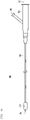
- the catheter 60 for using in the procedure simulator 10 is provided with a catheter main body 62, the balloon 64 that is provided to a distal end portion of the catheter main body 62 and can inflate and deflate, and a hub 66 that is coupled to a proximal portion of the catheter main body 62.
- the balloon 64 communicates with an inflation port 68 provided to the hub 66 via an inflation lumen provided to the catheter main body 62.
- An inflation liquid is injected from the inflation port 68, whereby the balloon 64 inflates.
- FIG. 6 illustrates the balloon 64 in an inflated state. Note that, the inflation liquid is injected using a syringe or the like.
- the hub 66 includes an injection port 72 from which a therapeutic agent is injected into a blood vessel that extends in a segment serving as a target.
- the injection port 72 communicates with a terminal opening 70 of the catheter 60 via an injection lumen provided in the inside of the catheter main body 62.
- the therapeutic agent injected from the injection port 72 is introduced into the blood vessel from the terminal opening 70.
- the injection lumen also functions as a guide wire lumen.
- the procedure simulator 10 configured as the above acts as follows.
- the user After a user has assembled the procedure simulator 10 as illustrated in FIG. 2 , the user puts a liquid in the first storage tank 12.
- the liquid is preferably transparent so as to cause the user to visually recognize the change in the flow of a colored therapeutic agent or colored water due to a pressure difference, and water (tap water) that can be easily acquired and put away can be used.
- the user drives the pump 20.
- the pump 20 pumps up the liquid in the first storage tank 12, and supplies the liquid to the tissue model 18 through the catheter introduction member 24.
- the liquid flows in the flow path 38 and the bifurcated flow paths 40a to 40f and 42 of the tissue model 18, and is stored in the second storage tank 14 through the pipes 22.
- the liquid in the second storage tank 14 flows back to the first storage tank 12 through the reflux pipe 56.
- the pump 20 the liquid in the first storage tank 12 continuously circulates in a route passing through the catheter introduction member 24, the tissue model 18, the pipes 22, the second storage tank 14, and the reflux pipe 56, and returning to the first storage tank 12.
- the liquid surface of the liquid is kept at a position of the discharge port 54. Accordingly, a water pressure corresponding to a difference ⁇ H1 between the height of the tissue model 18 and the height of the liquid surface of the second storage tank 14 acts on the bifurcated flow paths 40a to 40f and 42 in the inside of the tissue model 18. In this state, the liquid flows through each bifurcated flow path 42 of the tissue model 18 at the approximately same flow rate, and can simulate flows of the healthy hepatic artery 102 having no cancer tissue.
- the user inserts the catheter 60 into the tissue model 18 through the catheter introduction member 24.
- the user can check a behavior of a simulated therapeutic agent when administering the simulated therapeutic agent from the terminal opening 70 of the catheter 60 in a state where the balloon 64 does not inflate.
- the user can visually identify the flow of the healthy hepatic artery 102 by injecting colored water being colored as a simulated therapeutic agent.
- the user operates the three-way stopcock 48 of the pipe 22 coupled to the predetermined bifurcated flow path 42, and causes the bifurcated flow path 42 to communicate with the drain flow path 50. Accordingly, the liquid in the predetermined bifurcated flow path 42 is discharged from a terminal portion of the drain flow path 50 that is present at a position lower than that of the tissue model 18. The water pressure of the predetermined bifurcated flow path 42 is decreased by the amount corresponding to a drop ⁇ H2 between the tissue model 18 and the liquid surface of the third storage tank 16.
- a pressure difference corresponding to ⁇ H1+ ⁇ H2 is generated between the bifurcated flow path 42 that communicates with the second storage tank 14 and the bifurcated flow path 42 that communicates with the drain flow path 50.
- the flow of the hepatic artery 102 in a case where a tumor tissue is generated in a predetermined segment can be simulated by causing the bifurcated flow path 42 to communicate with the drain flow path 50.
- the user injects colored water from the terminal opening 70 of the catheter 60.
- the colored water flows through all of the bifurcated flow paths 42 at the downstream side of the terminal opening 70. This is because the water pressure sent out by the pump 20 is higher than an internal pressure of the bifurcated flow path 42 that communicates with the drain flow path 50 and an internal pressure of the bifurcated flow path 42 that communicates with the second storage tank 14.
- the user can visually identify the behavior of the simulated therapeutic agent in a case where the bifurcated flow path 40a and the interlock flow path 45 at the upstream side of the bifurcated portion 34b are occluded by inflating the balloon 64 of the catheter 60 at the upstream of the bifurcated portion 34b.
- the user injects colored water from the terminal opening 70 of the catheter main body 62.
- the colored water simulates a contrast medium or a therapeutic agent.
- the bifurcated flow path 40a and the interlock flow paths 45 at the upstream side are occluded with the balloon 64, the bifurcated flow paths 40a, 40c, 40d, and 42 at the downstream side of the balloon 64 receive no pressure by the pump 20.
- the pressure of the bifurcated flow path 42 that communicates with the second storage tank 14 is relatively higher than the pressure of the bifurcated flow path 42 that communicates with the drain flow path 50. Accordingly, the liquid is drawn toward the bifurcated flow path 42 that communicates with the drain flow path 50 from the bifurcated flow path 42 that communicates with the second storage tank 14. In this state, when injecting the colored water from the terminal opening 70 of the catheter main body 62, the user can visually identify a state where the colored water selectively flows into the bifurcated flow path 42 communicated with the drain flow path 50.
- the liquid in the second storage tank 14 flows back from the bifurcated flow path 42 that communicates with the second storage tank 14, so that it is possible to generate with stability a state where the liquid flows only into the bifurcated flow path 42 that communicates with the drain flow path 50.
- This state is maintained for a comparatively long period of time until the liquid in the first storage tank 12 becomes empty. Therefore, the user can perform training that includes changing the occluded position of the balloon 64 to various positions, changing the position of the bifurcated flow path 42 that communicates with the drain flow path 50, and the like. Accordingly, the user can develop a better understanding of the behavior of the simulated therapeutic agent.
- the colored water flowed into the bifurcated flow path 42 that communicates with the drain flow path 50 dyes the filter member 46 when passing through the filter member 46 that simulates a cancer tissue. Accordingly, the user can visually identify that the therapeutic agent has selectively reached the cancer tissue.
- the colored water may include a solid embolization material.
- the solid embolization material gelatin, spherical plastic (bead), a fluorescent piece, and the like are suitably used.
- the procedure simulator 10 according to the embodiment exhibits the following effects.
- the first storage tank 12 that stores therein a liquid imitating blood
- the tissue model 18 including the plurality of the bifurcated flow paths 40a to 40f and 42 being bifurcated toward the downstream via the plurality of the bifurcated portions 34a to 34g, the bifurcated portions 34a to 34g and the bifurcated flow paths 40a to 40f and 42 being formed at the same height
- the pump 20 that supplies the liquid in the first storage tank 12 to the tissue model 18
- the second storage tank 14 that stores therein the liquid to be flowed out from the bifurcated flow paths 42
- the pipe 22 that connects the outlet of the bifurcated flow path 42 to the second storage tank 14
- the three-way stopcock 48 switching valve
- the filter member 46 that is provided on a way of the pipe 22 between the three-way stopcock 48 and
- a pressure difference can be generated between the bifurcated flow path 42 communicated with the drain flow path 50 and the bifurcated flow path 42 not communicated with the drain flow path 50, whereby a cancer tissue can be simulated by the filter member 46 provided at the downstream side of the bifurcated flow path 42. Further, by visually identifying the filter member 46, it is possible to cause the user to actually realize that the therapeutic agent can be selectively administered to a specific site.
- the abovementioned procedure simulator 10 may be configured such that the pipe 22 is coupled to a vicinity of a lower end of the second storage tank 14, and the liquid surface of the liquid in the second storage tank 14 is maintained at a position higher than the tissue model 18. Accordingly, a pressure corresponding to the difference ⁇ H1 in height between the liquid surface of the second storage tank 14 and the tissue model 18 acts on the bifurcated flow path 42 that communicates with the second storage tank 14.
- the pipe 22 may be coupled to the second storage tank 14 at the same height as the tissue model 18. With such a configuration, it is possible to make the flow resistance and the pressure that act on each bifurcated flow path 42 in the tissue model 18 uniform.
- the abovementioned procedure simulator 10 may be provided with the reflux pipe 56 that is coupled to the second storage tank 14 at a position higher than the pipe 22, and causes the liquid in the second storage tank 14 to flow back to the first storage tank 12. Accordingly, it is possible to prevent the amount of the liquid in the inside of the first storage tank 12 from decreasing with time, so that the user can perform the simulation of the procedure for a longer period of time.
- the filter members 46 provided to the respective bifurcated flow paths 42 are disposed side by side in a line in the downstream side of the tissue model 18. Accordingly, the user can easily visually identify a difference between the filter member 46 in which a tumor is simulated and the other filter members 46.
- the abovementioned procedure simulator 10 is provided with the third storage tank 16 that contains the liquid discharged from the drain flow path 50, and the liquid surface of the third storage tank 16 can be set to a position lower than the tissue model 18. Accordingly, it is possible to generate a pressure difference corresponding to the sum of the difference ⁇ H1 and the drop ⁇ H2 between the liquid surface of the third storage tank 16 and the tissue model 18, between the bifurcated flow path 42 communicated with the drain flow path 50 and the bifurcated flow path 42 communicated with the second storage tank 14.
- the second storage tank 14 may be provided at a position separated from the tissue model 18 in a horizontal direction, and the third storage tank 16 may be disposed between the second storage tank 14 and the tissue model 18. Accordingly, it is possible to dispose the third storage tank 16 below the three-way stopcock 48, and simplify the routing of the drain flow path 50.
- the first storage tank 12 may be disposed below the tissue model 18. Accordingly, the tissue model 18 of the procedure simulator 10 is disposed in a compact manner.
- the tissue model 18 and the pipe 22 may be formed of a transparent material. Accordingly, the user can directly visually identify the flow of the colored water, and can easily actually realize that the therapeutic agent can be selectively administered to a specific site.
- a procedure training method is a procedure training method that uses the abovementioned procedure simulator 10, and includes: a step of filling a liquid in the first storage tank 12; a step of driving the pump 20 to cause the liquid to circulate among the first storage tank 12, the tissue model 18, and the second storage tank 14; a step of discharging the liquid from the drain flow path 50 via the three-way stopcock 48 (switching valve) of the pipe 22 coupled to an outlet of the predetermined bifurcated flow path 42; a step of inserting the catheter 60 into the tissue model 18 and occluding an upstream portion of the bifurcated flow path 42 that communicates with the drain flow path 50 with the balloon 64; and a step of causing colored water (a contrast medium or a therapeutic agent) to flow from a distal end of the balloon 64.
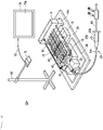
- a procedure simulator 10A includes, in addition to the device configuration illustrated in FIG. 2 , an imaging device 76 that images the tissue model 18 and the pipe 22, and a display device 78 that displays video imaged by the imaging device 76.
- the imaging device 76 includes, for example, a smartphone, a compact camera, or the like, and is disposed above the tissue model 18 and the pipes 22 with a stand 80.
- a planar illumination device that illuminates the tissue model 18, the pipes 22, and the filter members 46 may be provided under the third storage tank 16.
- the imaging device 76 images video of the tissue model 18 and the pipe 22 seen from the upper side.
- the imaging device 76 is coupled to the display device 78, for example, via a communication cable 82 such as a USB cable, and video data imaged by the imaging device 76 is sent to the display device 78.
- the display device 78 that is a device having a comparative large display screen 78a, for example, a liquid crystal monitor, a screen, a tablet terminal, or the like can be used.
- the image (video) imaged by the imaging device 76 is displayed in real time on the display screen 78a of the display device 78.
- the procedure simulator 10A can be also used for the training of operating the catheter 60 while watching a planar image that appears on the display screen 78a of the display device 78. With such the training, it is possible to grasp the operation of the catheter 60 and the flow of the colored water under the condition similar to the actual procedure that the user performs while watching an X-ray fluoroscope.
- the present invention has been described with the preferred embodiments, however, the present invention is not limited to the embodiments, and it is needless to say that various modifications are possible without deviating from the scope of the invention. Even in a case where a cancer and tumor tissue generated in an organ other than the liver is used as a target, tissue models in accordance with target organs are combined, whereby the present invention can be implemented.
Landscapes
- Engineering & Computer Science (AREA)
- General Physics & Mathematics (AREA)
- Physics & Mathematics (AREA)
- Health & Medical Sciences (AREA)
- Computational Mathematics (AREA)
- Mathematical Optimization (AREA)
- Medical Informatics (AREA)
- Medicinal Chemistry (AREA)
- Chemical & Material Sciences (AREA)
- Algebra (AREA)
- Theoretical Computer Science (AREA)
- Educational Technology (AREA)
- Mathematical Analysis (AREA)
- General Health & Medical Sciences (AREA)
- Mathematical Physics (AREA)
- Pure & Applied Mathematics (AREA)
- Business, Economics & Management (AREA)
- Educational Administration (AREA)
- Radiology & Medical Imaging (AREA)
- Pulmonology (AREA)
- Nuclear Medicine, Radiotherapy & Molecular Imaging (AREA)
- Instructional Devices (AREA)
- Infusion, Injection, And Reservoir Apparatuses (AREA)
Abstract
Description
- This disclosure relates to a procedure simulator that is used for training of a procedure using a catheter, and a procedure training method using the same.
- Procedures in which a diagnostic agent such as a contrast medium or a therapeutic agent such as an anticancer agent or an embolization material is administered through a catheter inserted into an artery to conduct a diagnosis and treatment, with respect to liver cancer, prostate tumor, uterine fibroid, and the like have been known. In the treatment, it is desirable to selectively administer the therapeutic agent to a tissue of the cancer, the tumor, or the like, and prevent the therapeutic agent from flowing into a normal tissue as much as possible.
- In recent years, a procedure such as balloon occluded trans arterial chemo embolization (B-TACE) in which attention is focused on the concentration of arterial flows because minute artery blood vessels are formed in the cancer tissue is reported below.
-
US Patent No. 9844383 - Irie et al., "Dense Accumulation of Lipiodol Emulsion in Hepatocellular Carcinoma Nodule during Selective Balloon-occluded Arterial Stump Pressure", Cardio Vascular and Intervention Radiology, 2013, No. 36, p. 706-713
- Matsumoto et al., "Balloon-occluded arterial stump pressure before balloon-occluded transarterial chemoembolization", Minimally Invasive Therapy & Allied Technologies, Volume 25, 2016
- B-TACE is a percutaneous treatment procedure in which an artery upstream of a cancer tissue where arterial flows are concentrated is occluded with a balloon of a catheter distal end portion, whereby a local difference (also called pressure difference) in blood pressure between a normal tissue and the tissue of a cancer, a tumor, or the like is be generated. B-TACE is characterized in that a therapeutic agent is administered from a distal end side of the balloon inserted into the blood vessel and caused to inflate, whereby the therapeutic agent is specifically concentrated to a treatment site.
- However, it is difficult for a doctor who is familiar with the conventional treatment to intuitively understand the blood flow that is generated locally in the living body and under a limited condition, and the fact is that it is difficult to say that these procedures are widely used in medical practice.
- Therefore, there is a demand for a procedure simulator and a procedure training method using the same with which it is possible to actually realize that a therapeutic agent can be selectively administered to a specific region due to a pressure difference that is generated by occluding an inside of a blood vessel with a balloon.
- One aspect of the disclosure below is a procedure simulator including: a first storage tank that stores therein a liquid; a tissue model including a plurality of bifurcated flow paths being bifurcated downstream via a plurality of bifurcated portions, the bifurcated portions and the bifurcated flow paths being formed at a same height; a pump that supplies the liquid in the first storage tank to the tissue model; a second storage tank that stores therein the liquid to be flowed out from the bifurcated flow paths; a pipe that connects an outlet of the bifurcated flow path to the second storage tank; a switching valve that is provided on a way of the pipe, and selectively causes the bifurcated flow path to communicate with a drain flow path from which the liquid is discharged below the second storage tank; and a filter member that is provided on a way of the pipe between the switching valve and the outlet of the bifurcated flow path.
- Another aspect is a procedure training method that uses the procedure simulator of the one aspect, and the procedure training method includes: a step of filling the liquid in the first storage tank; a step of driving the pump to cause the liquid to circulate among the first storage tank, the tissue model, and the second storage tank; a step of discharging the liquid from the drain flow path via the switching valve of the pipe coupled to the outlet of the predetermined bifurcated flow path; a step of inserting a catheter into the tissue model, and occluding an upstream portion of the bifurcated flow path that communicates with the drain flow path, with the balloon; and a step of causing a contrast medium or a therapeutic agent to flow from a distal end of the balloon.
- With the procedure simulator and the procedure training method using the same in the abovementioned aspects, it is possible to generate a pressure difference between the bifurcated flow paths by providing switching valves and filter members in the downstream parts on the bifurcated flow paths, and to cause a user to actually realize that the therapeutic agent can be selectively administered to a specific region with the filter member.
-
- [
FIG. 1] FIG. 1 is a schematic view of a liver. - [
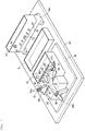
FIG. 2] FIG. 2 is a plan view of a procedure simulator according to a first embodiment. - [
FIG. 3] FIG. 3 is a perspective view of the procedure simulator ofFIG. 2 in a state where pipes and a catheter introduction member are removed. - [
FIG. 4] FIG. 4 is a cross-sectional view of a tissue model of the procedure simulator ofFIG. 2 . - [
FIG. 5] FIG. 5 is a schematic view illustrating a circulation route of a liquid in the procedure simulator ofFIG. 2 . - [
FIG. 6] FIG. 6 is a plan view of a catheter that is used for the procedure simulator ofFIG. 2 . - [
FIG. 7] FIG. 7 is an explanation view illustrating a flow of the liquid when a drain flow path is communicated with a predetermined bifurcated flow path in the procedure simulator ofFIG. 2 . - [
FIG. 8] FIG. 8 is an explanation view illustrating the flow of the liquid when an upstream side of the bifurcated flow path is occluded with a balloon, in the operation of the procedure simulator ofFIG. 7 . - [
FIG. 9] FIG. 9 is a perspective view of a procedure simulator according to a second embodiment. - The following describes preferred embodiments of the present invention in details with reference to the accompanying drawings.
- The present embodiment describes a procedure simulator 10 (see
FIG. 2 ) that simulates treatment for liver cancer. - A
liver 100 is the largest organ in an abdominal region of a human being, and ducts such as ahepatic artery 102, ahepatic vein 104, a bile duct, and a portal vein are led thereto, as illustrated inFIG. 1 . Note that, inFIG. 1 , illustrations of the bile duct and the portal vein are omitted. According to the anatomical classification by Claude Couinaud, theliver 100 is classified into eight subsegments of S1 to S8. In the drawing, S1 is caudate lobe, S2 is a left lateral posterior segment, S3 is a left lateral anterior segment, S4 is a left medial segment, S5 is a right anterior inferior segment, S6 is a right posterior inferior segment, S7 is a right posterior superior segment, and S8 is a right anterior superior segment. Each subsegment is functionally independent, and includes a duct into and out of which blood or the like flows. Accordingly, in the specification and the treatment of a lesion area, it is important to classify the liver into eight subsegments. - In treatment for liver cancer, a procedure in which a catheter 60 (see
FIG. 6 ) is inserted from thehepatic artery 102, and a therapeutic agent is administered selectively to a subsegment in which a cancer tissue is formed, is performed. In the cancer tissue, a large number of minute artery blood vessels are formed. Therefore, in the subsegment where the cancer tissue is present, the blood in thehepatic artery 102 becomes easy to locally flow, thereby generating a local difference (pressure difference) in blood pressure with thehepatic artery 102 in a normal subsegment where no cancer tissue is present. Here, when a predetermined site of thehepatic artery 102 is occluded with aballoon 64 in a distal end portion of thecatheter 60, the blood selectively flows toward the cancer tissue due to the pressure difference. By using the flow of the blood, it is possible to perform a procedure of selectively administering a therapeutic agent to a segment where the cancer tissue is present. - As illustrated in
FIG. 2 , theprocedure simulator 10 according to the embodiment simulates the abovementioned artery of theliver 100, and includes atissue model 18 including eight bifurcatedflow paths 42 being bifurcated so as to correspond to the eight subsegments. The bifurcatedflow paths 42 in theprocedure simulator 10 respectively simulate arteries that are connected to the respective subsegments (S1 to S8) in theliver 100, and are used in the training of the cancer treatment using thecatheter 60. - The
procedure simulator 10 includes afirst storage tank 12, asecond storage tank 14, athird storage tank 16, thetissue model 18, apump 20,pipes 22, and acatheter introduction member 24, as illustrated. Among them, thefirst storage tank 12, thesecond storage tank 14, thethird storage tank 16, thetissue model 18, thepump 20, and thepipes 22 are disposed onto aflat support plate 26. At least each of thefirst storage tank 12, thesecond storage tank 14, thethird storage tank 16, thetissue model 18, and thepump 20 can be attached onto thesupport plate 26, which makes it easy to be carried and set. - As illustrated in
FIG. 3 , atray 28 is mounted on thesupport plate 26. Thetray 28 is a plate-like member for collectively supporting thefirst storage tank 12, thetissue model 18, and thepump 20, and includes one end to which thefirst storage tank 12 is disposed. Thetray 28 includes the other end to which asupport 28a that supports an upstream portion (a starting end portion 36) of thetissue model 18 is provided. Moreover, thepump 20 is disposed between thesupport 28a and thefirst storage tank 12 on thetray 28. Thefirst storage tank 12 is attachable and detachable to and from thetray 28. - The
first storage tank 12 is a container in which a liquid to be introduced into thetissue model 18 is stored, and is formed in a rectangular shape in a plan view. Thefirst storage tank 12 is disposed under thetissue model 18. Thefirst storage tank 12 is formed of a resin material such as acrylic resin. Thefirst storage tank 12 may include an opening portion in an upper end thereof. - The
pump 20 includes, for example, a centrifugal pump, and pumps up a liquid stored in thefirst storage tank 12 to thetissue model 18 that is provided above thefirst storage tank 12. As illustrated inFIG. 2 , a suction port of thepump 20 is coupled to thefirst storage tank 12 via asuction flow path 29. One end of adischarge pipe 27 is coupled to a discharge port of thepump 20. The other end of thedischarge pipe 27 is coupled to aliquid supply inlet 24b bifurcated from anintroduction port 24a of thecatheter introduction member 24. - The
catheter introduction member 24 is provided with a flexible tubularmain body portion 24c, and theintroduction port 24a provided at a proximal side of themain body portion 24c. A distal side of themain body portion 24c is coupled to thestarting end portion 36 of thetissue model 18, and theintroduction port 24a and theliquid supply inlet 24b communicate with aflow path 38 of thetissue model 18 through themain body portion 24c. A liquid discharged from thepump 20 is sent into thestarting end portion 36 of thetissue model 18 through thecatheter introduction member 24. - The
introduction port 24a simulates an insertion port from which thecatheter 60 is inserted into a blood vessel. Theintroduction port 24a is provided with a valve, which is not illustrated, that allows thecatheter 60 to be inserted and prevents the liquid in an inside of thecatheter introduction member 24 from leaking. - As illustrated in
FIG. 3 , thetissue model 18 is disposed above thefirst storage tank 12. Thetissue model 18 is attached onto a plate-like support member 30. Thesupport member 30 is a flat plate-like member that is bridged over so as to cover a part of an upper end opening portion of thefirst storage tank 12, and is provided with aprojection portion 30a to be inserted into anengagement hole 18a of thetissue model 18, on a top face side thereof. Pipe guides 31 that guide bent parts of thepipes 22 are respectively provided on both side portions of thesupport member 30. Thepipe guide 31 is a U-character shaped groove that can hold thepipe 22 in an inside thereof. Thepipe guide 31 includes a pair ofside wall portions 31a curved in a circular arc shape in a plan view, and holds thepipe 22 in a state of being curved along thepipe guide 31, between the pair of theseside wall portions 31a, thereby preventing thepipe 22 from being occluded. Thetissue model 18 includes theengagement hole 18a that is fitted into theprojection portion 30a, and is fixed onto thesupport member 30 in a simplified manner via thepipes 22 held by the pipe guides 31. - As illustrated in
FIG. 4 , thetissue model 18 is provided to a flowpath formation block 32 that is made of a transparent material such as acrylic resin. Note that, thetissue model 18 may include a soft material (rubber material) such as silicon resin. The flowpath formation block 32 configures thetissue model 18 and includes a plurality ofbifurcated portions 34, as illustrated, and eightbifurcated flow paths 42 being bifurcated from the startingend portion 36 at the upstream side toward the downstream side in a shape of a tree diagram. Abifurcated portion 34a is formed in the closest portion to the startingend portion 36, and theflow path 38 is bifurcated into twobifurcated flow paths bifurcated portion 34a. Thebifurcated flow paths flow path 38 at the upstream side of thebifurcated portion 34a are formed to each have an equal length. -
Bifurcated portions bifurcated flow paths bifurcated portion 34b, thebifurcated flow path 40a is bifurcated into twobifurcated flow paths bifurcated flow path 40a is bifurcated into thebifurcated flow paths bifurcated portion 34c, thebifurcated flow path 40b is bifurcated into twobifurcated flow paths bifurcated flow path 40b is bifurcated into thebifurcated flow paths bifurcated flow paths 40c to 40f are formed so as to each have an approximately equal length. -
Bifurcated portions 34d to 34g are respectively formed to terminals of thebifurcated flow paths 40c to 40f. In each of thebifurcated portions 34d to 34g, each of thebifurcated flow paths 40c to 40f is further bifurcated into twobifurcated flow paths 42. In other words, thetissue model 18 eventually includes the eightbifurcated flow paths 42 being bifurcated. Each of thebifurcated flow paths 40c to 40f is bifurcated intobifurcated flow paths 42 in left and right directions at the equal angle with respect to each of thebifurcated flow paths 40c to 40f at the upstream side, and the eightbifurcated flow paths 42 are formed so as to each have an approximate same length. - In the
tissue model 18, the flow path length from the startingend portion 36 to the terminal of eachbifurcated flow path 42 is the same. Moreover, all of thebifurcated portions 34a to 34g and thebifurcated flow paths 40a to 40f and 42 are formed on the same plane. Accordingly, eachbifurcated flow path 42 in thetissue model 18 can have an equivalent flow rate. The eightbifurcated flow paths 42 respectively simulate the eight arteries to be connected to the subsegments S1 to S8 in the liver 100 (seeFIG. 1 ). - Moreover, in the
tissue model 18, in the downstream of each of thebifurcated portions 34a to 34g, a plurality ofinterlock flow paths 45 that connect thebifurcated flow paths 40a to 40f and 42 to each other are provided. Theseinterlock flow paths 45 imitate collateral blood flows of a tissue. Thebifurcated flow paths 40a to 40f and 42 in the inside of thetissue model 18 are formed such that an inside diameter thereof becomes smaller at about 70 to 90% of the inside diameter before the bifurcation for every time each bifurcated flow path passes through each of thebifurcated portions 34a to 34g. The inside diameter after the bifurcation is preferably set to about 80% (78 to 82%) of the inside diameter before the bifurcation in order to be closer to a tube tissue of human being. For example, in a case where the inside diameter of theflow path 38 at a side of the startingend portion 36 is set to 5 mm, the inside diameter of each of thebifurcated flow paths bifurcated flow paths 40c to 40f can be set to about 3.3 mm. Moreover, the inside diameter of thebifurcated flow path 42 can be set to about 2.8 mm. In addition, the inside diameter of theinterlock flow path 45 can be set to about 1.5 to 1.8 mm. - As for such the
tissue model 18, two resin plates having a thickness about half of that of thetissue model 18 are prepared, and grooves corresponding to theflow path 38, thebifurcated flow paths 40a to 40f and 42, and theinterlock flow paths 45 are formed in each resin plate. Further, the two resin plates are overlapped and joined to each other such that the grooves correspond to each other, thereby forming thetissue model 18. -
Connection ports 44 serving as outlets of thebifurcated flow paths 42 are respectively provided to terminals of thebifurcated flow paths 42. As illustrated inFIG. 2 , one ends of thepipes 22 are respectively coupled to theconnection ports 44. The eightpipes 22 corresponding to the eightbifurcated flow paths 42 are provided. Thepipes 22 extend toward thesecond storage tank 14, and the other ends of thepipes 22 are respectively coupled toconnection ports 52 of thesecond storage tank 14. Note that, thepipes 22 in both side portions that are largely inclined from the direction toward thesecond storage tank 14 are respectively guided by the pipe guides 31 and curved to the directions toward thesecond storage tank 14. - A
filter member 46 and a three-way stopcock 48 are provided to each of thepipes 22. Thefilter member 46 is provided at the upstream side (in other words, at a side of thetissue model 18 from the three-way stopcock 48) of the three-way stopcock 48, and simulates a cancer cell. Thefilter members 46 are disposed side by side in a line on thefirst storage tank 12. As illustrated inFIG. 5 , thefilter member 46 is provided with acylindrical casing 46a, and afilter 46b filled in an inside of thecasing 46a. In order to allow the discoloration of thefilter 46b to be visually identified, thecasing 46a is formed of a raw material such as a transparent resin material with which the inside can be visually identified. Thefilter 46b is formed of a white or pale color material, and is colored when a coloring agent imitating a therapeutic agent or a colored embolic agent is passed therethrough. A user can check that the therapeutic agent has reached a target site by visually identify the coloration of thefilter 46b. Moreover, when the embolic agent is flowed into an inside of thecasing 46a of thefilter member 46, the user can visually identify that the embolic agent is gradually accumulated in the inside of thefilter 46b. In addition, when the occlusion of thefilter 46b is progressed, the user can visually identify that the inflow velocity of the embolic agent flowing into thefilter 46b is lowered. This phenomenon simulates the change in the flow of the liquid similar in a phenomenon in which an embolic agent is accumulated in cancer and tumor tissues in an actual living body. Accordingly, the user can actually check that the therapeutic agent is selectively administered to a specified site. Thefilter 46b is connected so as to be attachable and detachable to and from thepipe 22. In other words, thefilter 46b can also be a disposable member, and in this case, only thefilter 46b can be removed from theprocedure simulator 10 and discarded. - A
drain flow path 50 for discharging a liquid discharged from thebifurcated flow path 42 to a site lower than thetissue model 18 is coupled to the three-way stopcock 48. The three-way stopcock 48 causes thebifurcated flow path 42 to selectively communicate with thesecond storage tank 14 or thedrain flow path 50. When thebifurcated flow path 42 is communicated with thesecond storage tank 14 by the three-way stopcock 48, the liquid flows into thesecond storage tank 14 through thepipe 22. Moreover, when thebifurcated flow path 42 is communicated with thedrain flow path 50 by the three-way stopcock 48, the liquid discharged from thebifurcated flow path 42 is discharged at a position lower than thetissue model 18 through thedrain flow path 50. The three-way stopcock 48 switches the flow path, thereby discharging the liquid from thedrain flow path 50. The liquid discharged from thedrain flow path 50 is stored in thethird storage tank 16. - As illustrated in
FIGS. 2 and3 , thesecond storage tank 14 is a storage tank formed in a rectangular shape in a plan view, and stores therein liquids discharged from thepipes 22. The volumetric capacity of thesecond storage tank 14 is smaller than the volumetric capacity of thefirst storage tank 12. As illustrated inFIG. 3 , thesecond storage tank 14 is provided such that a position of a bottom thereof is in the vicinity of an upper end of thefirst storage tank 12 with aseating 14a. Note that, thesecond storage tank 14 is attachable and detachable to and from thesupport plate 26 or theseating 14a. - Moreover, the
second storage tank 14 is provided with the eightconnection ports 52 provided in the vicinity of a bottom portion thereof and onedischarge port 54 provided in the vicinity of an upper end thereof. End portions of thepipes 22 at the downstream side are respectively coupled to the eightconnection ports 52 that are provided at the same height. An end portion of areflux pipe 56 at the upstream side is coupled to thedischarge port 54. - As illustrated in
FIG. 5 , an end portion of thereflux pipe 56 at the downstream side is disposed in the inside of thefirst storage tank 12. In thesecond storage tank 14, the liquid is stored up to the height of thedischarge port 54. When the liquid surface reaches the position of thedischarge port 54, the liquid is discharged from thesecond storage tank 14 via thedischarge port 54. The liquid discharged from thedischarge port 54 flows in thereflux pipe 56 due to the drop, and flows back to thefirst storage tank 12. - The
third storage tank 16 is a storage tank disposed between thefirst storage tank 12 and thesecond storage tank 14, and is formed in a rectangular shape in a plan view. In an inside of thethird storage tank 16, a terminal of thedrain flow path 50 is disposed. Thethird storage tank 16 stores therein the liquid discharged from thedrain flow path 50. Thethird storage tank 16 is formed of, for example, a transparent material such as acrylic resin, and an illumination unit such as a reflection plate or plane-type light-emitting equipment is disposed at a lower surface side thereof, thereby allowing irradiation of illuminating light from a side below thepipes 22 and thefilter members 46. Note that, thethird storage tank 16 may be fixed so as to be attachable and detachable to and from thesupport plate 26. - As illustrated in
FIG. 6 , thecatheter 60 for using in theprocedure simulator 10 is provided with a cathetermain body 62, theballoon 64 that is provided to a distal end portion of the cathetermain body 62 and can inflate and deflate, and ahub 66 that is coupled to a proximal portion of the cathetermain body 62. Theballoon 64 communicates with aninflation port 68 provided to thehub 66 via an inflation lumen provided to the cathetermain body 62. An inflation liquid is injected from theinflation port 68, whereby theballoon 64 inflates. Note that,FIG. 6 illustrates theballoon 64 in an inflated state. Note that, the inflation liquid is injected using a syringe or the like. - The
hub 66 includes an injection port 72 from which a therapeutic agent is injected into a blood vessel that extends in a segment serving as a target. The injection port 72 communicates with aterminal opening 70 of thecatheter 60 via an injection lumen provided in the inside of the cathetermain body 62. The therapeutic agent injected from the injection port 72 is introduced into the blood vessel from theterminal opening 70. Note that, the injection lumen also functions as a guide wire lumen. - Next, the
procedure simulator 10 configured as the above acts as follows. - After a user has assembled the
procedure simulator 10 as illustrated inFIG. 2 , the user puts a liquid in thefirst storage tank 12. The liquid is preferably transparent so as to cause the user to visually recognize the change in the flow of a colored therapeutic agent or colored water due to a pressure difference, and water (tap water) that can be easily acquired and put away can be used. - Next, after the user has checked that the three-
way stopcocks 48 of all thepipes 22 have communicated with thesecond storage tank 14, the user drives thepump 20. Thepump 20 pumps up the liquid in thefirst storage tank 12, and supplies the liquid to thetissue model 18 through thecatheter introduction member 24. The liquid flows in theflow path 38 and thebifurcated flow paths 40a to 40f and 42 of thetissue model 18, and is stored in thesecond storage tank 14 through thepipes 22. As illustrated inFIG. 5 , the liquid in thesecond storage tank 14 flows back to thefirst storage tank 12 through thereflux pipe 56. As mentioned above, by thepump 20, the liquid in thefirst storage tank 12 continuously circulates in a route passing through thecatheter introduction member 24, thetissue model 18, thepipes 22, thesecond storage tank 14, and thereflux pipe 56, and returning to thefirst storage tank 12. - In the
second storage tank 14, the liquid surface of the liquid is kept at a position of thedischarge port 54. Accordingly, a water pressure corresponding to a difference ΔH1 between the height of thetissue model 18 and the height of the liquid surface of thesecond storage tank 14 acts on thebifurcated flow paths 40a to 40f and 42 in the inside of thetissue model 18. In this state, the liquid flows through eachbifurcated flow path 42 of thetissue model 18 at the approximately same flow rate, and can simulate flows of the healthyhepatic artery 102 having no cancer tissue. - Next, the user inserts the
catheter 60 into thetissue model 18 through thecatheter introduction member 24. The user can check a behavior of a simulated therapeutic agent when administering the simulated therapeutic agent from theterminal opening 70 of thecatheter 60 in a state where theballoon 64 does not inflate. The user can visually identify the flow of the healthyhepatic artery 102 by injecting colored water being colored as a simulated therapeutic agent. - Thereafter, as illustrated in
FIG. 7 , the user operates the three-way stopcock 48 of thepipe 22 coupled to the predeterminedbifurcated flow path 42, and causes thebifurcated flow path 42 to communicate with thedrain flow path 50. Accordingly, the liquid in the predeterminedbifurcated flow path 42 is discharged from a terminal portion of thedrain flow path 50 that is present at a position lower than that of thetissue model 18. The water pressure of the predeterminedbifurcated flow path 42 is decreased by the amount corresponding to a drop ΔH2 between thetissue model 18 and the liquid surface of thethird storage tank 16. Accordingly, a pressure difference corresponding to ΔH1+ΔH2 is generated between thebifurcated flow path 42 that communicates with thesecond storage tank 14 and thebifurcated flow path 42 that communicates with thedrain flow path 50. In this manner, the flow of thehepatic artery 102 in a case where a tumor tissue is generated in a predetermined segment can be simulated by causing thebifurcated flow path 42 to communicate with thedrain flow path 50. - Next, in a state where the
balloon 64 does not inflate, the user injects colored water from theterminal opening 70 of thecatheter 60. In the state where theballoon 64 does not inflate, the colored water flows through all of thebifurcated flow paths 42 at the downstream side of theterminal opening 70. This is because the water pressure sent out by thepump 20 is higher than an internal pressure of thebifurcated flow path 42 that communicates with thedrain flow path 50 and an internal pressure of thebifurcated flow path 42 that communicates with thesecond storage tank 14. - Next, as illustrated in
FIG. 8 , the user can visually identify the behavior of the simulated therapeutic agent in a case where thebifurcated flow path 40a and theinterlock flow path 45 at the upstream side of thebifurcated portion 34b are occluded by inflating theballoon 64 of thecatheter 60 at the upstream of thebifurcated portion 34b. In a state where theballoon 64 has inflated, the user injects colored water from theterminal opening 70 of the cathetermain body 62. The colored water simulates a contrast medium or a therapeutic agent. Since thebifurcated flow path 40a and theinterlock flow paths 45 at the upstream side are occluded with theballoon 64, thebifurcated flow paths balloon 64 receive no pressure by thepump 20. - In this case, the pressure of the
bifurcated flow path 42 that communicates with thesecond storage tank 14 is relatively higher than the pressure of thebifurcated flow path 42 that communicates with thedrain flow path 50. Accordingly, the liquid is drawn toward thebifurcated flow path 42 that communicates with thedrain flow path 50 from thebifurcated flow path 42 that communicates with thesecond storage tank 14. In this state, when injecting the colored water from theterminal opening 70 of the cathetermain body 62, the user can visually identify a state where the colored water selectively flows into thebifurcated flow path 42 communicated with thedrain flow path 50. The liquid in thesecond storage tank 14 flows back from thebifurcated flow path 42 that communicates with thesecond storage tank 14, so that it is possible to generate with stability a state where the liquid flows only into thebifurcated flow path 42 that communicates with thedrain flow path 50. This state is maintained for a comparatively long period of time until the liquid in thefirst storage tank 12 becomes empty. Therefore, the user can perform training that includes changing the occluded position of theballoon 64 to various positions, changing the position of thebifurcated flow path 42 that communicates with thedrain flow path 50, and the like. Accordingly, the user can develop a better understanding of the behavior of the simulated therapeutic agent. - Moreover, the colored water flowed into the
bifurcated flow path 42 that communicates with thedrain flow path 50 dyes thefilter member 46 when passing through thefilter member 46 that simulates a cancer tissue. Accordingly, the user can visually identify that the therapeutic agent has selectively reached the cancer tissue. Moreover, the colored water may include a solid embolization material. As for the solid embolization material, gelatin, spherical plastic (bead), a fluorescent piece, and the like are suitably used. When the user has caused the solid embolization material to flow, the user can check a state where thefilter member 46 becomes gradually clogged, and can grasp the change in the flow of the blood when thefilter member 46 serving as a simulated tumor tissue has been clogged. - The
procedure simulator 10 according to the embodiment exhibits the following effects. - In the embodiment: the
first storage tank 12 that stores therein a liquid imitating blood; thetissue model 18 including the plurality of thebifurcated flow paths 40a to 40f and 42 being bifurcated toward the downstream via the plurality of thebifurcated portions 34a to 34g, thebifurcated portions 34a to 34g and thebifurcated flow paths 40a to 40f and 42 being formed at the same height; thepump 20 that supplies the liquid in thefirst storage tank 12 to thetissue model 18; thesecond storage tank 14 that stores therein the liquid to be flowed out from thebifurcated flow paths 42; thepipe 22 that connects the outlet of thebifurcated flow path 42 to thesecond storage tank 14; the three-way stopcock 48 (switching valve) that is provided on a way of thepipe 22 and selectively causes thebifurcated flow paths 42 to communicate with thedrain flow path 50 from which the liquid is discharged below thesecond storage tank 14; and thefilter member 46 that is provided on a way of thepipe 22 between the three-way stopcock 48 and the outlet of thebifurcated flow path 42 and includes an inside that can be visually identified, are provided. - With the
abovementioned procedure simulator 10, by operating the three-way stopcock 48 (switching valve), a pressure difference can be generated between thebifurcated flow path 42 communicated with thedrain flow path 50 and thebifurcated flow path 42 not communicated with thedrain flow path 50, whereby a cancer tissue can be simulated by thefilter member 46 provided at the downstream side of thebifurcated flow path 42. Further, by visually identifying thefilter member 46, it is possible to cause the user to actually realize that the therapeutic agent can be selectively administered to a specific site. - The
abovementioned procedure simulator 10 may be configured such that thepipe 22 is coupled to a vicinity of a lower end of thesecond storage tank 14, and the liquid surface of the liquid in thesecond storage tank 14 is maintained at a position higher than thetissue model 18. Accordingly, a pressure corresponding to the difference ΔH1 in height between the liquid surface of thesecond storage tank 14 and thetissue model 18 acts on thebifurcated flow path 42 that communicates with thesecond storage tank 14. - In the
abovementioned procedure simulator 10, thepipe 22 may be coupled to thesecond storage tank 14 at the same height as thetissue model 18. With such a configuration, it is possible to make the flow resistance and the pressure that act on eachbifurcated flow path 42 in thetissue model 18 uniform. - The
abovementioned procedure simulator 10 may be provided with thereflux pipe 56 that is coupled to thesecond storage tank 14 at a position higher than thepipe 22, and causes the liquid in thesecond storage tank 14 to flow back to thefirst storage tank 12. Accordingly, it is possible to prevent the amount of the liquid in the inside of thefirst storage tank 12 from decreasing with time, so that the user can perform the simulation of the procedure for a longer period of time. - In the
abovementioned procedure simulator 10, thefilter members 46 provided to the respectivebifurcated flow paths 42 are disposed side by side in a line in the downstream side of thetissue model 18. Accordingly, the user can easily visually identify a difference between thefilter member 46 in which a tumor is simulated and theother filter members 46. - The
abovementioned procedure simulator 10 is provided with thethird storage tank 16 that contains the liquid discharged from thedrain flow path 50, and the liquid surface of thethird storage tank 16 can be set to a position lower than thetissue model 18. Accordingly, it is possible to generate a pressure difference corresponding to the sum of the difference ΔH1 and the drop ΔH2 between the liquid surface of thethird storage tank 16 and thetissue model 18, between thebifurcated flow path 42 communicated with thedrain flow path 50 and thebifurcated flow path 42 communicated with thesecond storage tank 14. - In the
abovementioned procedure simulator 10, thesecond storage tank 14 may be provided at a position separated from thetissue model 18 in a horizontal direction, and thethird storage tank 16 may be disposed between thesecond storage tank 14 and thetissue model 18. Accordingly, it is possible to dispose thethird storage tank 16 below the three-way stopcock 48, and simplify the routing of thedrain flow path 50. - In the
abovementioned procedure simulator 10, thefirst storage tank 12 may be disposed below thetissue model 18. Accordingly, thetissue model 18 of theprocedure simulator 10 is disposed in a compact manner. - In the
abovementioned procedure simulator 10, thetissue model 18 and thepipe 22 may be formed of a transparent material. Accordingly, the user can directly visually identify the flow of the colored water, and can easily actually realize that the therapeutic agent can be selectively administered to a specific site. - Moreover, a procedure training method according to the embodiment is a procedure training method that uses the
abovementioned procedure simulator 10, and includes: a step of filling a liquid in thefirst storage tank 12; a step of driving thepump 20 to cause the liquid to circulate among thefirst storage tank 12, thetissue model 18, and thesecond storage tank 14; a step of discharging the liquid from thedrain flow path 50 via the three-way stopcock 48 (switching valve) of thepipe 22 coupled to an outlet of the predeterminedbifurcated flow path 42; a step of inserting thecatheter 60 into thetissue model 18 and occluding an upstream portion of thebifurcated flow path 42 that communicates with thedrain flow path 50 with theballoon 64; and a step of causing colored water (a contrast medium or a therapeutic agent) to flow from a distal end of theballoon 64. - With the abovementioned procedure training method, it is possible to generate a pressure difference between the
bifurcated flow paths 42, and simulate a cancer tissue by thefilter member 46. Further, by causing the colored water to flow from the distal end of theballoon 64, it is possible to cause the user to actually realize that the therapeutic agent can be selectively administered to thefilter member 46 in which a cancer tissue is imitated. - As illustrated in
FIG. 9 , aprocedure simulator 10A according to the present embodiment includes, in addition to the device configuration illustrated inFIG. 2 , animaging device 76 that images thetissue model 18 and thepipe 22, and adisplay device 78 that displays video imaged by theimaging device 76. - The
imaging device 76 includes, for example, a smartphone, a compact camera, or the like, and is disposed above thetissue model 18 and thepipes 22 with astand 80. A planar illumination device that illuminates thetissue model 18, thepipes 22, and thefilter members 46 may be provided under thethird storage tank 16. Theimaging device 76 images video of thetissue model 18 and thepipe 22 seen from the upper side. Theimaging device 76 is coupled to thedisplay device 78, for example, via acommunication cable 82 such as a USB cable, and video data imaged by theimaging device 76 is sent to thedisplay device 78. - As for the
display device 78 that is a device having a comparativelarge display screen 78a, for example, a liquid crystal monitor, a screen, a tablet terminal, or the like can be used. The image (video) imaged by theimaging device 76 is displayed in real time on thedisplay screen 78a of thedisplay device 78. - The
procedure simulator 10A according to the embodiment can be also used for the training of operating thecatheter 60 while watching a planar image that appears on thedisplay screen 78a of thedisplay device 78. With such the training, it is possible to grasp the operation of thecatheter 60 and the flow of the colored water under the condition similar to the actual procedure that the user performs while watching an X-ray fluoroscope. - In the above, the present invention has been described with the preferred embodiments, however, the present invention is not limited to the embodiments, and it is needless to say that various modifications are possible without deviating from the scope of the invention. Even in a case where a cancer and tumor tissue generated in an organ other than the liver is used as a target, tissue models in accordance with target organs are combined, whereby the present invention can be implemented.
Claims (11)
- A procedure simulator comprising:a first storage tank that stores therein a liquid;a tissue model including a plurality of bifurcated flow paths being bifurcated downstream via a plurality of bifurcated portions, the bifurcated portions and the bifurcated flow paths being formed at a same height;a pump that supplies the liquid in the first storage tank to the tissue model;a second storage tank that stores therein the liquid to be flowed out from the bifurcated flow paths;a pipe that connects an outlet of the bifurcated flow path to the second storage tank;a switching valve that is provided on a way of the pipe, and selectively causes the bifurcated flow path to communicate with a drain flow path from which the liquid is discharged below the second storage tank; anda filter member that is provided on a way of the pipe between the switching valve and the outlet of the bifurcated flow path.
- The procedure simulator according to claim 1, wherein the pipe is coupled to a vicinity of a lower end of the second storage tank, and a liquid surface of the liquid in the second storage tank is maintained at a position higher than the tissue model.
- The procedure simulator according to claim 2, wherein the pipe is coupled to the second storage tank at a same height as the tissue model.
- The procedure simulator according to claim 3, further comprising a reflux pipe that is coupled to the second storage tank at a position higher than the pipe, and causes the liquid in the second storage tank to flow back to the first storage tank.
- The procedure simulator according to any one of claims 1 to 3, wherein the filter members that are provided to the respective bifurcated flow paths are disposed side by side in a line.
- The procedure simulator according to any one of claims 1 to 4, further comprising a third storage tank that contains the liquid to be discharged from the drain flow path, wherein a liquid surface of the third storage tank is present at a position lower than the tissue model.
- The procedure simulator according to claim 6, wherein the second storage tank is provided at a position separated from the tissue model in a horizontal direction, and the third storage tank is disposed between the second storage tank and the tissue model.
- The procedure simulator according to any one of claims 1 to 7, wherein the first storage tank is disposed below the tissue model.
- The procedure simulator according to any one of claims 1 to 8, further comprising: an imaging device that images the tissue model and the pipe; and a display device that displays video imaged by the imaging device.
- The procedure simulator according to claim 9, further comprising an illumination device that illuminates the tissue model, the pipe, and the filter member.
- A procedure training method that uses a procedure simulator including:a first storage tank that stores therein a liquid;a tissue model including a plurality of bifurcated flow paths being bifurcated downstream via a plurality of bifurcated portions, the bifurcated portions and the bifurcated flow paths being formed at a same height;a pump that supplies the liquid in the first storage tank to the tissue model;a second storage tank that stores therein the liquid to be flowed out from the bifurcated flow paths;a pipe that connects an outlet of the bifurcated flow path to the second storage tank;a switching valve that is provided on a way of the pipe, and selectively causes the bifurcated flow path to communicate with a drain flow path from which the liquid is discharged below the second storage tank; anda filter member that is provided on a way of the pipe between the switching valve and the outlet of the bifurcated flow path, the procedure training method comprising:a step of filling the liquid in the first storage tank;a step of driving the pump to cause the liquid to circulate among the first storage tank, the tissue model, and the second storage tank;a step of discharging the liquid from the drain flow path via the switching valve of the pipe coupled to the outlet of the predetermined bifurcated flow path;a step of inserting a catheter into the tissue model, and occluding an upstream portion of the bifurcated flow path that communicates with the drain flow path, with a balloon; anda step of causing a contrast medium or a therapeutic agent to flow from a distal end of the balloon.
Applications Claiming Priority (2)
| Application Number | Priority Date | Filing Date | Title |
|---|---|---|---|
| JP2020017102 | 2020-02-04 | ||
| PCT/JP2021/000614 WO2021157285A1 (en) | 2020-02-04 | 2021-01-12 | Procedure simulator, and procedure practice method using same |
Publications (2)
| Publication Number | Publication Date |
|---|---|
| EP4086879A1 true EP4086879A1 (en) | 2022-11-09 |
| EP4086879A4 EP4086879A4 (en) | 2023-06-28 |
Family
ID=77200465
Family Applications (1)
| Application Number | Title | Priority Date | Filing Date |
|---|---|---|---|
| EP21750616.1A Pending EP4086879A4 (en) | 2020-02-04 | 2021-01-12 | Procedure simulator, and procedure practice method using same |
Country Status (6)
| Country | Link |
|---|---|
| US (1) | US12288475B2 (en) |
| EP (1) | EP4086879A4 (en) |
| JP (1) | JP7571062B2 (en) |
| CN (1) | CN114556458B (en) |
| AU (1) | AU2021215474B2 (en) |
| WO (1) | WO2021157285A1 (en) |
Families Citing this family (1)
| Publication number | Priority date | Publication date | Assignee | Title |
|---|---|---|---|---|
| WO2023239859A1 (en) * | 2022-06-10 | 2023-12-14 | The Johns Hopkins University | Apparatus for developing and testing devices and methods for embolizing a blood vessel |
Family Cites Families (25)
| Publication number | Priority date | Publication date | Assignee | Title |
|---|---|---|---|---|
| US5338662A (en) * | 1992-09-21 | 1994-08-16 | Bio-Preserve Medical Corporation | Organ perfusion device |
| US5634797A (en) * | 1995-05-05 | 1997-06-03 | Montgomery; Mary B. | Heart defect teaching aid |
| GB9615802D0 (en) * | 1996-07-26 | 1996-09-04 | Harris P L | Simulation system |
| AU2006203753A1 (en) * | 2005-09-06 | 2007-03-22 | Thoratec Corporation | Mock Circulatory Apparatus |
| US20140322688A1 (en) * | 2006-03-03 | 2014-10-30 | EBM Corporation | System for evaluating cardiac surgery training |
| US8608484B2 (en) * | 2008-03-04 | 2013-12-17 | Medrad, Inc. | Dynamic anthropomorphic cardiovascular phantom |
| US9965591B2 (en) | 2011-09-13 | 2018-05-08 | Medtronic, Inc. | Physiologic simulator system |
| JP6317885B2 (en) * | 2013-03-01 | 2018-04-25 | テルモ株式会社 | Training equipment |
| US9844383B2 (en) | 2013-05-08 | 2017-12-19 | Embolx, Inc. | Devices and methods for low pressure tumor embolization |
| US20140370490A1 (en) * | 2013-06-12 | 2014-12-18 | Medtronic, Inc. | Heart-lung preparation and method of use |
| JP6408838B2 (en) | 2014-09-09 | 2018-10-17 | テルモ株式会社 | Training equipment |
| JP6452715B2 (en) * | 2014-11-10 | 2019-01-16 | 国立大学法人大阪大学 | Catheter simulator and contrast method for catheter simulator |
| JP6454527B2 (en) * | 2014-12-02 | 2019-01-16 | 株式会社ブリヂストン | Storage tank, siphon drainage system and outflow pipe connection member |
| US9852660B1 (en) * | 2015-12-03 | 2017-12-26 | Robert Fairbanks | Catheterization procedure training apparatus |
| WO2017127724A1 (en) * | 2016-01-21 | 2017-07-27 | The University Of North Carolina At Chapel Hill | Simulator systems and methods |
| JP6551845B2 (en) * | 2016-02-12 | 2019-07-31 | 学校法人早稲田大学 | Durability test apparatus and test method for medical test object |
| DE102016108152A1 (en) * | 2016-05-02 | 2017-11-02 | Universität Zu Lübeck | Three-dimensional vascular surgical simulation model and associated manufacturing process |
| CN206194241U (en) * | 2016-08-17 | 2017-05-24 | 有研医疗器械(北京)有限公司 | Aorta wicresoft intervenes operation analogue means |
| IT201600114762A1 (en) * | 2016-11-14 | 2018-05-14 | Milano Politecnico | TEST ASSEMBLY TO SIMULATE CARDIOSURGERY AND / OR INTERVENTIONAL CARDIOLOGY PROCEDURES |
| US10885813B2 (en) * | 2016-11-29 | 2021-01-05 | Prytime Medical Devices, Inc. | Body model for temporary hemorrhage control training and simulation |
| FR3067220B1 (en) * | 2017-06-13 | 2019-07-26 | Centre National De La Recherche Scientifique | DEVICE FOR INFUSION OF AN ORGAN |
| CN111107893B (en) | 2017-06-26 | 2023-07-14 | 曼泰斯公司 | Systems and methods for intravascular fluid injection simulation |
| EP3792900B1 (en) * | 2018-08-07 | 2023-04-19 | TERUMO Kabushiki Kaisha | Technique simulator |
| US11682320B2 (en) * | 2018-09-21 | 2023-06-20 | Mentice, Ab | Cardiac simulation device |
| US11176849B2 (en) * | 2018-10-29 | 2021-11-16 | The Aga Khan University | Pumping heart simulator |
-
2021
- 2021-01-12 CN CN202180005945.0A patent/CN114556458B/en active Active
- 2021-01-12 EP EP21750616.1A patent/EP4086879A4/en active Pending
- 2021-01-12 JP JP2021575674A patent/JP7571062B2/en active Active
- 2021-01-12 AU AU2021215474A patent/AU2021215474B2/en active Active
- 2021-01-12 WO PCT/JP2021/000614 patent/WO2021157285A1/en not_active Ceased
-
2022
- 2022-08-01 US US17/816,479 patent/US12288475B2/en active Active
Also Published As
| Publication number | Publication date |
|---|---|
| US12288475B2 (en) | 2025-04-29 |
| CN114556458B (en) | 2024-01-30 |
| WO2021157285A1 (en) | 2021-08-12 |
| JPWO2021157285A1 (en) | 2021-08-12 |
| US20220392374A1 (en) | 2022-12-08 |
| CN114556458A (en) | 2022-05-27 |
| AU2021215474B2 (en) | 2025-12-04 |
| EP4086879A4 (en) | 2023-06-28 |
| AU2021215474A1 (en) | 2022-06-23 |
| JP7571062B2 (en) | 2024-10-22 |
Similar Documents
| Publication | Publication Date | Title |
|---|---|---|
| US11417242B2 (en) | Technique simulator | |
| US6790043B2 (en) | Method and apparatus for surgical training | |
| JPH07502443A (en) | Bidirectional femoral artery cannula | |
| MX2007008129A (en) | Retrograde perfusion of tumor sites. | |
| JP2009034462A (en) | Perfusion system for therapy of pancreas | |
| CN103886798A (en) | High-simulation interventional operation trainer | |
| CN117241846B (en) | Syringe-based microbubble generator with aerator | |
| CA2951568A1 (en) | Selectively delivering particles into the distal portion of the left gastric artery | |
| US12288475B2 (en) | Procedure simulator and procedure training method using the same | |
| CN208927391U (en) | Dual balloon catheter device for gastrointestinal anastomosis | |
| CN213150114U (en) | Cardiovascular intervention operation training or teaching system | |
| JP2015150078A (en) | Blood flow retaining-type blood vessel endoscope system | |
| JP4977340B2 (en) | Drug perfusion equipment for para-aortic lymph node tumors | |
| JP6941357B2 (en) | Coping training device for ruptured cerebral aneurysm during surgery | |
| HK40038387A (en) | A surgical simulator | |
| CN111833712A (en) | Cardiovascular interventional operation training or teaching system and method | |
| HK40038387B (en) | A surgical simulator | |
| Kreel | The pancreas: newer radiological methods of investigation | |
| JP2018143667A (en) | Balloon catheter and balloon position confirmation system | |
| JP2024505005A (en) | Syringe type microbubble generator with aerator |
Legal Events
| Date | Code | Title | Description |
|---|---|---|---|
| STAA | Information on the status of an ep patent application or granted ep patent |
Free format text: STATUS: THE INTERNATIONAL PUBLICATION HAS BEEN MADE |
|
| PUAI | Public reference made under article 153(3) epc to a published international application that has entered the european phase |
Free format text: ORIGINAL CODE: 0009012 |
|
| STAA | Information on the status of an ep patent application or granted ep patent |
Free format text: STATUS: REQUEST FOR EXAMINATION WAS MADE |
|
| 17P | Request for examination filed |
Effective date: 20220803 |
|
| AK | Designated contracting states |
Kind code of ref document: A1 Designated state(s): AL AT BE BG CH CY CZ DE DK EE ES FI FR GB GR HR HU IE IS IT LI LT LU LV MC MK MT NL NO PL PT RO RS SE SI SK SM TR |
|
| DAV | Request for validation of the european patent (deleted) | ||
| DAX | Request for extension of the european patent (deleted) | ||
| REG | Reference to a national code |
Ref country code: DE Ref legal event code: R079 Free format text: PREVIOUS MAIN CLASS: G09B0009000000 Ipc: G09B0023280000 |
|
| A4 | Supplementary search report drawn up and despatched |
Effective date: 20230525 |
|
| RIC1 | Information provided on ipc code assigned before grant |
Ipc: G09B 23/34 20060101ALN20230519BHEP Ipc: G09B 23/30 20060101ALI20230519BHEP Ipc: G09B 23/28 20060101AFI20230519BHEP |