EP4086728B1 - Portable electronic device - Google Patents
Portable electronic device Download PDFInfo
- Publication number
- EP4086728B1 EP4086728B1 EP22170774.8A EP22170774A EP4086728B1 EP 4086728 B1 EP4086728 B1 EP 4086728B1 EP 22170774 A EP22170774 A EP 22170774A EP 4086728 B1 EP4086728 B1 EP 4086728B1
- Authority
- EP
- European Patent Office
- Prior art keywords
- hinge
- input module
- display area
- display
- electronic device
- Prior art date
- Legal status (The legal status is an assumption and is not a legal conclusion. Google has not performed a legal analysis and makes no representation as to the accuracy of the status listed.)
- Active
Links
Images




Classifications
-
- G—PHYSICS
- G06—COMPUTING OR CALCULATING; COUNTING
- G06F—ELECTRIC DIGITAL DATA PROCESSING
- G06F1/00—Details not covered by groups G06F3/00 - G06F13/00 and G06F21/00
- G06F1/16—Constructional details or arrangements
- G06F1/1613—Constructional details or arrangements for portable computers
- G06F1/1615—Constructional details or arrangements for portable computers with several enclosures having relative motions, each enclosure supporting at least one I/O or computing function
- G06F1/1616—Constructional details or arrangements for portable computers with several enclosures having relative motions, each enclosure supporting at least one I/O or computing function with folding flat displays, e.g. laptop computers or notebooks having a clamshell configuration, with body parts pivoting to an open position around an axis parallel to the plane they define in closed position
-
- G—PHYSICS
- G06—COMPUTING OR CALCULATING; COUNTING
- G06F—ELECTRIC DIGITAL DATA PROCESSING
- G06F1/00—Details not covered by groups G06F3/00 - G06F13/00 and G06F21/00
- G06F1/16—Constructional details or arrangements
- G06F1/1613—Constructional details or arrangements for portable computers
- G06F1/1615—Constructional details or arrangements for portable computers with several enclosures having relative motions, each enclosure supporting at least one I/O or computing function
- G06F1/1624—Constructional details or arrangements for portable computers with several enclosures having relative motions, each enclosure supporting at least one I/O or computing function with sliding enclosures, e.g. sliding keyboard or display
-
- G—PHYSICS
- G06—COMPUTING OR CALCULATING; COUNTING
- G06F—ELECTRIC DIGITAL DATA PROCESSING
- G06F1/00—Details not covered by groups G06F3/00 - G06F13/00 and G06F21/00
- G06F1/16—Constructional details or arrangements
- G06F1/1613—Constructional details or arrangements for portable computers
- G06F1/1633—Constructional details or arrangements of portable computers not specific to the type of enclosures covered by groups G06F1/1615 - G06F1/1626
- G06F1/1637—Details related to the display arrangement, including those related to the mounting of the display in the housing
-
- G—PHYSICS
- G06—COMPUTING OR CALCULATING; COUNTING
- G06F—ELECTRIC DIGITAL DATA PROCESSING
- G06F1/00—Details not covered by groups G06F3/00 - G06F13/00 and G06F21/00
- G06F1/16—Constructional details or arrangements
- G06F1/1613—Constructional details or arrangements for portable computers
- G06F1/1633—Constructional details or arrangements of portable computers not specific to the type of enclosures covered by groups G06F1/1615 - G06F1/1626
- G06F1/1637—Details related to the display arrangement, including those related to the mounting of the display in the housing
- G06F1/1641—Details related to the display arrangement, including those related to the mounting of the display in the housing the display being formed by a plurality of foldable display components
-
- G—PHYSICS
- G06—COMPUTING OR CALCULATING; COUNTING
- G06F—ELECTRIC DIGITAL DATA PROCESSING
- G06F1/00—Details not covered by groups G06F3/00 - G06F13/00 and G06F21/00
- G06F1/16—Constructional details or arrangements
- G06F1/1613—Constructional details or arrangements for portable computers
- G06F1/1633—Constructional details or arrangements of portable computers not specific to the type of enclosures covered by groups G06F1/1615 - G06F1/1626
- G06F1/1637—Details related to the display arrangement, including those related to the mounting of the display in the housing
- G06F1/1647—Details related to the display arrangement, including those related to the mounting of the display in the housing including at least an additional display
- G06F1/165—Details related to the display arrangement, including those related to the mounting of the display in the housing including at least an additional display the additional display being small, e.g. for presenting status information
-
- G—PHYSICS
- G06—COMPUTING OR CALCULATING; COUNTING
- G06F—ELECTRIC DIGITAL DATA PROCESSING
- G06F1/00—Details not covered by groups G06F3/00 - G06F13/00 and G06F21/00
- G06F1/16—Constructional details or arrangements
- G06F1/1613—Constructional details or arrangements for portable computers
- G06F1/1633—Constructional details or arrangements of portable computers not specific to the type of enclosures covered by groups G06F1/1615 - G06F1/1626
- G06F1/1637—Details related to the display arrangement, including those related to the mounting of the display in the housing
- G06F1/1652—Details related to the display arrangement, including those related to the mounting of the display in the housing the display being flexible, e.g. mimicking a sheet of paper, or rollable
-
- G—PHYSICS
- G06—COMPUTING OR CALCULATING; COUNTING
- G06F—ELECTRIC DIGITAL DATA PROCESSING
- G06F1/00—Details not covered by groups G06F3/00 - G06F13/00 and G06F21/00
- G06F1/16—Constructional details or arrangements
- G06F1/1613—Constructional details or arrangements for portable computers
- G06F1/1633—Constructional details or arrangements of portable computers not specific to the type of enclosures covered by groups G06F1/1615 - G06F1/1626
- G06F1/1662—Details related to the integrated keyboard
- G06F1/1666—Arrangements for reducing the size of the integrated keyboard for transport, e.g. foldable keyboards, keyboards with collapsible keys
-
- G—PHYSICS
- G06—COMPUTING OR CALCULATING; COUNTING
- G06F—ELECTRIC DIGITAL DATA PROCESSING
- G06F1/00—Details not covered by groups G06F3/00 - G06F13/00 and G06F21/00
- G06F1/16—Constructional details or arrangements
- G06F1/1613—Constructional details or arrangements for portable computers
- G06F1/1633—Constructional details or arrangements of portable computers not specific to the type of enclosures covered by groups G06F1/1615 - G06F1/1626
- G06F1/1675—Miscellaneous details related to the relative movement between the different enclosures or enclosure parts
- G06F1/1677—Miscellaneous details related to the relative movement between the different enclosures or enclosure parts for detecting open or closed state or particular intermediate positions assumed by movable parts of the enclosure, e.g. detection of display lid position with respect to main body in a laptop, detection of opening of the cover of battery compartment
-
- G—PHYSICS
- G06—COMPUTING OR CALCULATING; COUNTING
- G06F—ELECTRIC DIGITAL DATA PROCESSING
- G06F1/00—Details not covered by groups G06F3/00 - G06F13/00 and G06F21/00
- G06F1/16—Constructional details or arrangements
- G06F1/1613—Constructional details or arrangements for portable computers
- G06F1/1633—Constructional details or arrangements of portable computers not specific to the type of enclosures covered by groups G06F1/1615 - G06F1/1626
- G06F1/1675—Miscellaneous details related to the relative movement between the different enclosures or enclosure parts
- G06F1/1681—Details related solely to hinges
-
- G—PHYSICS
- G06—COMPUTING OR CALCULATING; COUNTING
- G06F—ELECTRIC DIGITAL DATA PROCESSING
- G06F1/00—Details not covered by groups G06F3/00 - G06F13/00 and G06F21/00
- G06F1/16—Constructional details or arrangements
- G06F1/1613—Constructional details or arrangements for portable computers
- G06F1/1633—Constructional details or arrangements of portable computers not specific to the type of enclosures covered by groups G06F1/1615 - G06F1/1626
- G06F1/1684—Constructional details or arrangements related to integrated I/O peripherals not covered by groups G06F1/1635 - G06F1/1675
- G06F1/1686—Constructional details or arrangements related to integrated I/O peripherals not covered by groups G06F1/1635 - G06F1/1675 the I/O peripheral being an integrated camera
-
- G—PHYSICS
- G06—COMPUTING OR CALCULATING; COUNTING
- G06F—ELECTRIC DIGITAL DATA PROCESSING
- G06F1/00—Details not covered by groups G06F3/00 - G06F13/00 and G06F21/00
- G06F1/16—Constructional details or arrangements
- G06F1/1613—Constructional details or arrangements for portable computers
- G06F1/1633—Constructional details or arrangements of portable computers not specific to the type of enclosures covered by groups G06F1/1615 - G06F1/1626
- G06F1/1684—Constructional details or arrangements related to integrated I/O peripherals not covered by groups G06F1/1635 - G06F1/1675
- G06F1/1688—Constructional details or arrangements related to integrated I/O peripherals not covered by groups G06F1/1635 - G06F1/1675 the I/O peripheral being integrated loudspeakers
-
- G—PHYSICS
- G06—COMPUTING OR CALCULATING; COUNTING
- G06F—ELECTRIC DIGITAL DATA PROCESSING
- G06F1/00—Details not covered by groups G06F3/00 - G06F13/00 and G06F21/00
- G06F1/16—Constructional details or arrangements
- G06F1/1613—Constructional details or arrangements for portable computers
- G06F1/1633—Constructional details or arrangements of portable computers not specific to the type of enclosures covered by groups G06F1/1615 - G06F1/1626
- G06F1/1684—Constructional details or arrangements related to integrated I/O peripherals not covered by groups G06F1/1635 - G06F1/1675
- G06F1/169—Constructional details or arrangements related to integrated I/O peripherals not covered by groups G06F1/1635 - G06F1/1675 the I/O peripheral being an integrated pointing device, e.g. trackball in the palm rest area, mini-joystick integrated between keyboard keys, touch pads or touch stripes
- G06F1/1692—Constructional details or arrangements related to integrated I/O peripherals not covered by groups G06F1/1635 - G06F1/1675 the I/O peripheral being an integrated pointing device, e.g. trackball in the palm rest area, mini-joystick integrated between keyboard keys, touch pads or touch stripes the I/O peripheral being a secondary touch screen used as control interface, e.g. virtual buttons or sliders
-
- G—PHYSICS
- G06—COMPUTING OR CALCULATING; COUNTING
- G06F—ELECTRIC DIGITAL DATA PROCESSING
- G06F1/00—Details not covered by groups G06F3/00 - G06F13/00 and G06F21/00
- G06F1/16—Constructional details or arrangements
- G06F1/20—Cooling means
- G06F1/203—Cooling means for portable computers, e.g. for laptops
-
- G—PHYSICS
- G06—COMPUTING OR CALCULATING; COUNTING
- G06F—ELECTRIC DIGITAL DATA PROCESSING
- G06F1/00—Details not covered by groups G06F3/00 - G06F13/00 and G06F21/00
- G06F1/16—Constructional details or arrangements
- G06F1/20—Cooling means
- G06F1/206—Cooling means comprising thermal management
-
- G—PHYSICS
- G06—COMPUTING OR CALCULATING; COUNTING
- G06F—ELECTRIC DIGITAL DATA PROCESSING
- G06F3/00—Input arrangements for transferring data to be processed into a form capable of being handled by the computer; Output arrangements for transferring data from processing unit to output unit, e.g. interface arrangements
- G06F3/01—Input arrangements or combined input and output arrangements for interaction between user and computer
- G06F3/048—Interaction techniques based on graphical user interfaces [GUI]
- G06F3/0481—Interaction techniques based on graphical user interfaces [GUI] based on specific properties of the displayed interaction object or a metaphor-based environment, e.g. interaction with desktop elements like windows or icons, or assisted by a cursor's changing behaviour or appearance
- G06F3/04817—Interaction techniques based on graphical user interfaces [GUI] based on specific properties of the displayed interaction object or a metaphor-based environment, e.g. interaction with desktop elements like windows or icons, or assisted by a cursor's changing behaviour or appearance using icons
Definitions
- the invention relates to an electronic device, and more particularly to a portable electronic device.
- notebook computers Due to advantages such as portability, multitasking, and high computing performance, notebook computers have become an indispensable tool for modern people in life or work.
- a common notebook computer adopts a single-screen configuration, or the size of the screen is fixed and may not be adjusted according to the user's operation requirements, thus lacking flexibility in operation.
- most of the cooling modules and speakers are mounted inside the host, thus causing issues such as insufficient cooling space and difficulty in significantly improving sound performance. Thus, the performance of the notebook computer and the user's operating experience are affected.
- Patent literature US 2004/108968 A1 relates to a user terminal provided with a base including a keyboard, a first display screen attached to the base along a primary fold line, a second display screen included in the base and located between the keyboard and the primary fold line, and at least one sliding piece for fixing the second display screen in a substantially flat configuration with the first display screen and/or with another part of the base.
- the first display screen, the second display screen, and the keyboard have substantially the same width, in order to fully utilize the width of the entire user terminal.
- Patent literature WO 2014/183565 A1 relates to a hybrid transformative tablet personal computer structure, including a base, an upper cover and a screen attached to the upper cover, wherein the base is composed of a first base portion, a second base portion, a third base portion, and an nth base portion respectively.
- the first base portion is connected to the second base portion via a first hinge
- the second base portion is connected to the third base portion via a second hinge
- the third base portion is connected to the fourth base portion via a third hinge
- the n-1th base portion is connected to the nth base portion via an n-1th hinge.
- the base and the upper cover can form a movable connection via a sliding rail-sliding chute mechanism or form a magnetic adsorption connection via a magnetic adsorption device.
- the invention provides a portable electronic device having excellent operation flexibility and improving the user's operating experience.
- the invention is set out in the appended set of claims.
- the invention provides a portable electronic device including a first body, a first hinge, a second body, a second hinge, a third body, and an input module.
- the second body is pivotally connected to the first body via the first hinge.
- the third body is pivotally connected to the second body via the second hinge, and the second body is located between the first body and the third body.
- the input module is slidably disposed on the third body and covers the second body. As the input module is slid away from the second hinge, the second body is uncovered by the input module.
- the input module includes a keyboard, a touch panel, or a touch display.
- the first body when the input module is slid close to the first hinge, the first body is adapted to be unfolded or closed at the second body via the first hinge.
- the first body When the input module is slid away from the first hinge, the first body is adapted to be unfolded or closed to the second body via the first hinge, and the second body is adapted to be unfolded or closed to the third body via the second hinge.
- the portable electronic device further includes a speaker disposed in the input module.
- the speaker when the input module is slid close to the first hinge, the speaker is accommodated in the third body. When the input module is slid away from the first hinge, the speaker is moved out of the third body.
- the portable electronic device further includes a heat dissipation module disposed in the third body, and the third body has an air outlet on a side away from the second hinge.
- the input module when the input module is slid close to the first hinge, the input module covers the air outlet. When the input module is slid away from the first hinge, the input module exposes the air outlet.
- the portable electronic device further includes a bottom plate disposed at a bottom of the third body.
- a width of the third body is less than a width of the bottom plate, and the width of the bottom plate is less than a sum of a width of the second body and the width of the third body.
- the second body when the input module is slid close to the first hinge, the second body is closed at the bottom plate.
- the second body is adapted to be unfolded or closed at the bottom plate via the second hinge.
- the portable electronic device further includes a camera disposed on the first body, and the first hinge is disposed between the camera and the second hinge.
- the camera and the first body are adapted to adjust a shooting angle and a shooting height via the first hinge.
- the camera, the first body, and the second body are adapted to adjust the shooting angle and the shooting height via the first hinge and the second hinge.
- the portable electronic device further includes a functional member disposed on the second body.
- the functional member includes a camera, a microphone, a speaker, or a display.
- the portable electronic device further includes a sensor disposed in the second body or the input module configured to sense whether the input module covers the second body.
- the senor includes a touch sensor or a proximity sensor.
- the sensor when the input module is slid close to the first hinge, the sensor senses that the input module covers the second body, and the display is in a dormant or disabled state.
- the sensor senses that the input module exposes the second body, and the display is in a wake-up or enabled state.
- the display is a flexible display disposed on the first body and the second body and covering the first hinge.
- the flexible display has a first display area and a second display area, respectively corresponding to the first body and the second body.
- the first display area and the first body are adapted to adjust an angle via the first hinge.
- the first display area, the first body, the second display area, and the second body are adapted to adjust the angle and a height via the first hinge and the second hinge.
- a length of the first display area is equal to a length of the second display area, and a width of the first display area is greater than a width of the second display area.
- the portable electronic device further includes a first sensor and a second sensor.
- the first sensor is disposed in the first body.
- the second sensor is disposed in the second body.
- the first sensor and the second sensor are configured to sense an included angle between the first body and the second body.
- the first sensor and second sensor include a gyroscope, a gravity sensor, or a magnetometer.
- the functional member when a display ratio of a display content of the display is equal to a display ratio of the first display area plus the second display area, and when the included angle between the first body and the second body is less than 180 degrees, the functional member prompts a user to adjust the included angle to 180 degrees.
- the functional member when a display ratio of a display content of the display is equal to a display ratio of the first display area, and the included angle between the first body and the second body is equal to 180 degrees, the functional member prompts a user to adjust the included angle to less than 180 degrees.
- the first display area and the second display area are adapted to switch between a first display mode, a second display mode, and a third display mode.
- the first display mode the first display area displays a first screen
- the second display area displays a second screen
- the first display area displays the second screen
- the second display area displays the first screen
- the third display mode the first display area displays a third screen
- the second display area displays the first screen.
- the first display area and the second display area are switched to a fourth display mode and display a fourth screen.
- the user may slide the input module according to the operation requirements, so that the second body is covered by the input module or uncovered by the input module to flexibly switch the operation mode, thus achieving excellent operation flexibility.
- the angle of the first body may be adjusted. After the second body is uncovered by the input module, the angle of the second body may be adjusted, while the angle and height of the first body may be adjusted synchronously with the rotation of the second body.
- the angle of the first body may be adjusted independently, and therefore the portable electronic device of the invention not only improves the operating comfort, but also improves the user's operating experience.
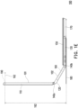
- FIG. 1A and FIG. 1B are schematic diagrams of a portable electronic device in a first state and a second state, respectively, of an embodiment of the invention.
- FIG. 1C and FIG. 1D are schematic side views of the portable electronic device of FIG. 1A and FIG. 1B , respectively.
- a portable electronic device 100 may be a notebook computer, and includes a first body 110, a second body 120, a third body 130, a first hinge 140a, a second hinge 140b, and an input module 150.
- the second body 120 is disposed between the first body 110 and the third body 130, wherein the second body 120 is pivotally connected to the first body 110 via the first hinge 140a, and the third body 130 is pivotally connected to the second body 120 via the second hinge 140b. That is, the first body 110 is adapted to be rotated relative to the second body 120 via the first hinge 140a, and the second body 120 is adapted to be rotated relative to the third body 130 via the second hinge 140b.
- the input module 150 is slidably disposed on the third body 130 and covers the second body 120 and the second hinge 140b.
- the second body 120 and the second hinge 140b are covered by the input module 150, the second body 120 temporarily may not be rotated relative to the third body 130 via the second hinge 140b.
- the first body 110 may be rotated relative to the second body 120 via the first hinge 140a to adjust the angle thereof (e.g., viewing angle).
- the input module 150 includes a keyboard 151 and a touch pad 152, and the keyboard 151 is located between the first hinge 140a and the touch pad 152.
- the input module may include any one of a keyboard, a touch panel, and a touch display, or a combination of at least two of the above.
- the input module 150 when the input module 150 is slid close to the first hinge 140a, the input module 150 covers the second body 120, the second hinge 140b, and the third body 130, and therefore the second body 120 temporarily may not be rotated relative to the third body 130 via the second hinge 140b.
- the first body 110 may be rotated relative to the second body 120 via the first hinge 140a to adjust the angle thereof (e.g., viewing angle). That is, the first body 110 is adapted to be unfolded or closed to the second body 120 via the first hinge 140a.
- the second body 120 and the second hinge 140b are moved out from under the input module 150 to be exposed to the outside, but the third body 130 is still covered by the input module 150.
- the second body 120 may be rotated relative to the third body 130 via the second hinge 140b to adjust the angle thereof (e.g., viewing angle).
- the angle (e.g., viewing angle) and height (e.g., viewing height) of the first body 110 may be adjusted synchronously with the rotation of the second body 120, or the angle (e.g., viewing angle) of the first body 110 may be adjusted independently. That is, the first body 110 is adapted to be unfolded or closed to the second body 120 via the first hinge 140a, and the second body 120 is adapted to be unfolded or closed to the third body 130 via the second hinge 140b.
- the first body 110 has a first display area 101
- the second body 120 has a second display area 102.
- the first display area 101 and the second display area 102 are separated from each other, and the first hinge 140a is located between the first display area 101 and the second display area 102.
- the first display area 101 and the second display area 102 form at least a portion of the display, wherein the first display area 101 may be used as a main display area, and the second display area 102 may be used as an auxiliary display area.
- the input module 150 when the input module 150 is slid close to the first hinge 140a, the input module 150 covers the second display area 102, and the user may view the screen displayed on the first display area 101 of the first body 110. At this time, the angle of the first body 110 is adjustable to adjust the viewing angle of the first display area 101.
- the second body 120 is moved out of the input module 150 so that the second display area 102 of the second body 120 is not covered by the input module 150 and is exposed to the outside. Therefore, the user may view the screen displayed in the first display area 101 and the screen displayed in the second display area 102 at the same time.
- the angle of the second body 120 is adjustable to adjust the viewing angle of the second display area 102, and, the angle and height of the first body 110 may be adjusted synchronously with the rotation of the second body 120, so as to adjust the viewing angle and viewing height of the first display area 101, or, the angle of the first body 110 may be adjusted independently to adjust the viewing angle of the first display area 101.
- the user may slide the input module 150 according to operation requirements to increase or decrease the number of display areas or scale the size of the display areas, thus achieving excellent operation flexibility.
- the viewing angle and viewing height of the first display area 101 are adjustable, and the viewing angle of the second display area 102 is adjustable, not only are the flexibility and comfort of operation improved, the user's operating experience is also improved.
- the second body 120 may be entirely or partially moved out from under input module 150 as the input module 150 is slid away from the second hinge 140b.
- the first display area 101 may be used as a main display area
- a part of the second display area 102 located outside of the input module 150 may be used as an auxiliary display area.
- the portable electronic device 100 further includes a sensor 160 disposed in the second body 120 and configured to sense whether the input module 150 covers the second body 120. As shown in FIG. 1A and FIG. 1C , when the input module 150 is slid close to the first hinge 140a, the sensor 160 senses that the input module 150 covers the second body 120 and the second display area 102 is in a sleep state or a disabled state. As shown in FIG. 1B and FIG.
- the sensor 160 senses that the second body 120 is moved out of the input module 150 and exposed to the outside, and the second display area 102 is awakened from the sleep state and switched to a wake-up or enabled state.
- the senor 160 may be a touch sensor or a proximity sensor, wherein the sensing mechanism of the touch sensor is based on whether the input module 150 is in contact with the second body 120.
- the sensing mechanism of the proximity sensor is based on changes in light, capacitance, inductance, magnetic field, or the like caused by the sliding of the input module 150.
- the sensor may be disposed in the input module, or both the second body and the input module may be provided with a sensor.
- the portable electronic device 100 further includes a speaker 170, wherein the speaker 170 is disposed in the input module 150 to slide close to the first hinge 140a or slide away from the first hinge 140a along with the input module 150.
- the speaker 170 is accommodated in the first body 110.
- the speaker 170 is moved out of the third body 130, in order to avoid the degradation of the sound performance of the speaker 170 due to the interference of the casing of the third body 130 or the components in the casing, thus improving the user's operating experience.
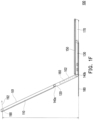
- FIG. 1E is a schematic side view of the portable electronic device of FIG. 1D converted to a third state.
- FIG. IF is a schematic side view of the portable electronic device of FIG. 1E converted to a fourth state.
- the input module 150 is slid away from the first hinge 140a
- the second body 120 is moved out of the input module 150 so that the second display area 102 of the second body 120 is not covered by the input module 150 and is exposed to the outside. Therefore, the user may view the screen displayed in the first display area 101 and the screen displayed in the second display area 102 at the same time.
- the angle of the second body 120 is adjustable to adjust the viewing angle of the second display area 102, and, the angle and height of the first body 110 may be adjusted synchronously with the rotation of the second body 120, so as to adjust the viewing angle and viewing height of the first display area 101, or, the angle of the first body 110 may be adjusted independently to adjust the viewing angle of the first display area 101.
- the portable electronic device 100 further includes a bottom plate 180 disposed at the bottom of the third body 130, and the second body 120 and the third body 130 are disposed on the bottom plate 180.
- the second body 120 is closed at the bottom plate 180.
- the second body 120 is adapted to be unfolded or closed at the bottom plate 180 via the second hinge 140b.
- the bottom plate 180 and the third body 130 may stably support the first body 110 and the second body 120 to prevent the portable electronic device 100 from shaking or falling.
- a width 130W of the third body 130 is less than a width 180W of the bottom plate 180, and the width 180W of the bottom plate 180 is less than the sum of a width 120W of the second body 120 and the width 130W of the third body 130.
- the portable electronic device 100 further includes a camera 190 disposed on the first body 110, and the first hinge 140a is disposed between the camera 190 and the second hinge 140b.
- the camera 190 and the first body 110 are adapted to adjust a shooting angle 191 and a shooting height 192 via the first hinge 140a. That is to say, the shooting angle 191 and the shooting height 192 of the camera 190 may be adjusted according to the rotation of the first body 110.
- the camera 190, the first body 110, and the second body 120 are adapted to adjust the shooting angle 191 and the shooting height 192 via the first hinge 140a and the second hinge 140b. That is to say, the shooting angle 191 and the shooting height 192 of the camera 190 may be adjusted according to the rotation of the first body 110 or the second body 120.
- FIG. 2 is a schematic diagram of a portable electronic device of another embodiment of the invention.
- a portable electronic device 100A of the present embodiment further includes a functional member 103, wherein the functional member 103 is disposed on the second body 120 and includes a camera 103a, a microphone 103b, and a speaker 103c.
- the second display area 102 may be a portion of the functional member 103, and the camera 103a, the microphone 103b, and the speaker 103c are located on the same side of the second display area 102.
- the type or quantity of the functional member 103 may be adjusted according to design requirements.
- FIG. 3A and FIG. 3B are schematic side views of a portable electronic device in a first state and a second state, respectively, of another embodiment of the invention. Please refer to FIG. 3A and FIG. 3B .
- a portable electronic device 100B of the present embodiment further includes a heat dissipation module 104 disposed in the third body 130, and the third body 130 has an air outlet 131 on a side away from the first hinge 140a.
- the input module 150 covers the air outlet 131.
- the air outlet 131 is not covered by the input module 150 and is exposed to the outside.
- the air outlet 131 not covered by the input module 150 and exposed to the outside may be used as another heat dissipation path of the heat dissipation module 104 (for example, an exhaust path of hot air), thus not only improving the heat dissipation efficiency of the portable electronic device 100B, but also improving the performance of the portable electronic device 100B.
- FIG. 4A to FIG. 4D are schematic side views of a portable electronic device in a first state to a fourth state, respectively, of another embodiment of the invention. Please refer to FIG. 4A to FIG. 4D .
- a portable electronic device 100C includes a flexible display 10 disposed on the first body 110 and the second body 120, wherein the flexible display 10 covers the first hinge 140a and has a first display area 101 corresponding to the first body 110 and a second display area 102 corresponding to the second body 120.
- first display area 101 and the second display area 102 are connected to each other, and as the first body 110 is rotated relative to the second body 120, a section in the flexible display 10 corresponding to the first hinge 140a (i.e., the section located in the first display area 101 and the second display area 102) may be bent accordingly.
- the first display area 101 and the first body 110 are adapted to adjust the angle via the first hinge 140a. That is to say, the viewing angle of the first display area 101 may be adjusted with the rotation of the first body 110.
- the first display area 101, the first body 110, the second display area 102, and the second body 120 are adapted to adjust the angle and height via the first hinge 140a and the second hinge 140b.
- the viewing angle and viewing height of the first display area 101 and the second display area 102 may be adjusted according to the rotation of the first body 110 or the second body 120. As shown in FIG. 4D , the included angle between the first display area 101 and the second display area 102 is equal to 180 degrees, and the flexible display 10 is in a flat state.
- FIG. 4E is a schematic diagram of the portable electronic device of FIG. 4C from another viewing angle.
- a length X1 of the first display area 101 is equal to a length X2 of the second display area 102, and a width Y1 of the first display area 101 is greater than a width Y2 of the second display area 102.
- the ratio of the length X1 to the width Y1 of the first display area 101 is 16:9, and the ratio of the length X2 to the width Y2 of the second display area 102 is 16:3.
- the ratio of the length X1 to the width (Yl+Y2) of the first display area 101 and the second display area 102 is 4:3.
- the ratio of the length X1 to the width Y1 of the first display area 101 is 8:5, and the ratio of the length X2 to the width Y2 of the second display area 102 is 8:3.
- the ratio of the length X1 to the width (Y1+Y2) of the first display area 101 and the second display area 102 is 1:1.
- a first sensor and a second sensor configured to sense the included angle between the first body 110 and the second body 120 may be further disposed on the first body 110 and the second body 120, respectively.
- the following is an example of the portable electronic device 100C.
- a first sensor 105 is disposed inside the first body 110
- a second sensor 106 is disposed inside the second body 120.
- the first sensor 105 and the second sensor 106 include a gyroscope, a gravity sensor, or a magnetometer configured to sense the included angle between the first body 110 and the second body 120.
- the first display area 101 and the second display area 102 may be switched between different display modes, or, when the included angle between the first body 110 and the second body 120 remains unchanged, the display modes of the first display area 101 and the second display area 102 are switched based on the operation command.
- the functional member when the display ratio of the display content of the display is equal to the display ratio of the first display area 101 plus the second display area 102 (for example, 4:3), and when the included angle between the first body 110 and the second body 120 is less than 180 degrees, the functional member prompts the user to adjust the included angle to 180 degrees.
- the display ratio of the display content of the display when the display ratio of the display content of the display is equal to the display ratio of the first display area 101 (for example, 16:9), and the included angle between the first body 110 and the second body 120 is equal to 180 degrees, the functional member prompts the user to adjust the included angle to less than 180 degrees.
- the functional member may be a speaker or a display prompting the user to adjust the included angle between the first body 110 and the second body 120 via sound or video.
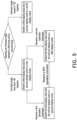
- FIG. 5 is a schematic diagram of a control flow of the display modes of a first display area and a second display area.
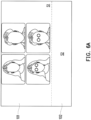
- FIG. 6A to FIG. 6D are schematic diagrams of a first display area and a second display area in a first display mode to a fourth display mode, respectively. Referring to FIG. 5 and FIG. 6A , when it is sensed that the included angle between the first body 110 and the second body 120 is less than 180 degrees, the first display area 101 and the second display area 102 are switched to the first display mode.
- the first display area 101 displays a first screen S1 (e.g., a portrait of a participant), and the second display area 102 displays a second screen S2 (e.g., information such as text, image, or video), as shown in FIG. 6A .
- a first screen S1 e.g., a portrait of a participant
- a second screen S2 e.g., information such as text, image, or video
- the display modes of the first display area 101 and the second display area 102 may be switched from the first display mode to the second display mode or switched back to the first display mode.
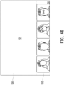
- the first display area 101 displays the second screen S2 (for example, information such as text, image, or video)
- the second display area 102 displays the first screen S1 (e.g., the portrait of a participant), as shown in FIG. 6B .
- the first screen S1 displayed in the display area 101 may be a main application screen, such as a webpage or a commonly used application program screen.
- the second screen S2 displayed in the second display area 102 may include shortcuts or icons of multiple applications.
- the display modes of the first display area 101 and the second display area 102 may be switched from the first display mode to the third display mode or switched back to the first display mode.
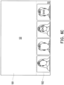
- the first display area 101 displays a third screen S3 (e.g., a screen sharing screen)
- the second display area 102 displays the first screen S1 (e.g., a portrait of a participant), as shown in FIG. 6C .
- the first display area 101 and the second display area 102 when the display modes of the first display area 101 and the second display area 102 are in the second display mode or the third display mode, and a third operation command is received, the first display area 101 and the second display area 102 in the second display mode may be switched to the third display mode. Conversely, the first display area 101 and the second display area 102 in the third display mode may be switched to the second display mode.
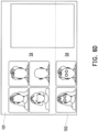
- the first display area 101 and the second display area 102 are switched to the fourth display mode.
- the first display area 101 and the second display area 102 jointly display a fourth screen S4, that is, the display ratio of the display content is equal to the display ratio of the first display plus the second display, such as the preset split screen of the application.
- the left half may display the portrait of the participant, while the right half may display information such as text, image, or video.
- the first display area 101 and the second display area 102 display a common screen
- the common screen may include computer desktop and shortcuts or icons of multiple applications, and the positions of the shortcuts or icons of the applications on the computer desktop may be adjusted according to the operation requirements of the user.
- the user may slide the input module according to the operation requirements, so that the second body is covered by the input module or removed from the input module to flexibly switch the operation mode, thus achieving excellent operation flexibility.
- the angle of the first body may be adjusted. After the second body is removed from the input module, the angle of the second body may be adjusted, and the angle and height of the first body may be adjusted synchronously with the rotation of the second body, or the angle of the first body may be adjusted independently. Therefore, the portable electronic device not only improves the flexibility and comfort in operation, but also improves the user's operating experience.
- the first body has a first display area
- the second body has a second display area.
- the user may view the screen displayed by the first display area of the first body.
- the angle of the first body is adjustable to adjust the viewing angle of the first display area.
- the second display area of the second body is not covered by the input module and is exposed to the outside. Therefore, the user may view the screen displayed in the first display area and the screen displayed in the second display area at the same time.
- the angle of the second body is adjustable to adjust the viewing angle of the second display area
- the angle and height of the first body may be adjusted synchronously with the rotation of the second body, so as to adjust the viewing angle and viewing height of the first display area, or, the angle of the first body may be adjusted independently to adjust the viewing angle of the first display area.
- the user may slide the input module according to operation requirements to increase or decrease the number of display areas or scale the size of the display areas, thus achieving excellent operation flexibility.
- the viewing angle and viewing height of the first display area are adjustable, and the viewing angle of the second display area is adjustable, not only are the flexibility and comfort of operation improved, the user's operating experience is also improved.
- the speaker module may be slid along with the input module and moved out of the third body, in order to avoid the degradation of the sound performance of the speaker due to the interference of the casing of the third body or the components in the casing, thus improving the user's operating experience.
- the third body has an air outlet on a side away from the second hinge, and is covered by the input module. As the input module is slid away from the first hinge, the air outlet is not covered by the input module and is exposed to the outside to be used as another heat dissipation path for the heat dissipation module, thus not only improving the heat dissipation efficiency of the portable electronic device, but also improving the performance of the portable electronic device.
Landscapes
- Engineering & Computer Science (AREA)
- Theoretical Computer Science (AREA)
- Computer Hardware Design (AREA)
- Physics & Mathematics (AREA)
- General Engineering & Computer Science (AREA)
- Human Computer Interaction (AREA)
- General Physics & Mathematics (AREA)
- Mathematical Physics (AREA)
- Telephone Set Structure (AREA)
- Lock And Its Accessories (AREA)
- Eye Examination Apparatus (AREA)
Description
- The invention relates to an electronic device, and more particularly to a portable electronic device.
- Due to advantages such as portability, multitasking, and high computing performance, notebook computers have become an indispensable tool for modern people in life or work. However, a common notebook computer adopts a single-screen configuration, or the size of the screen is fixed and may not be adjusted according to the user's operation requirements, thus lacking flexibility in operation. Moreover, most of the cooling modules and speakers are mounted inside the host, thus causing issues such as insufficient cooling space and difficulty in significantly improving sound performance. Thus, the performance of the notebook computer and the user's operating experience are affected.
- Patent literature
US 2003/021085 A1 relates to a multi-functional computing device including a space saving and configuration technique utilizing multiple joints disposed between multiple sections to facilitate rotational orientation of the sections to adapt to space limitations. - Patent literature
US 2004/108968 A1 relates to a user terminal provided with a base including a keyboard, a first display screen attached to the base along a primary fold line, a second display screen included in the base and located between the keyboard and the primary fold line, and at least one sliding piece for fixing the second display screen in a substantially flat configuration with the first display screen and/or with another part of the base. The first display screen, the second display screen, and the keyboard have substantially the same width, in order to fully utilize the width of the entire user terminal. - Patent literature
WO 2014/183565 A1 relates to a hybrid transformative tablet personal computer structure, including a base, an upper cover and a screen attached to the upper cover, wherein the base is composed of a first base portion, a second base portion, a third base portion, and an nth base portion respectively. The first base portion is connected to the second base portion via a first hinge, the second base portion is connected to the third base portion via a second hinge, the third base portion is connected to the fourth base portion via a third hinge and the n-1th base portion is connected to the nth base portion via an n-1th hinge. The base and the upper cover can form a movable connection via a sliding rail-sliding chute mechanism or form a magnetic adsorption connection via a magnetic adsorption device. - The invention provides a portable electronic device having excellent operation flexibility and improving the user's operating experience. The invention is set out in the appended set of claims.
- The invention provides a portable electronic device including a first body, a first hinge, a second body, a second hinge, a third body, and an input module. The second body is pivotally connected to the first body via the first hinge. The third body is pivotally connected to the second body via the second hinge, and the second body is located between the first body and the third body. The input module is slidably disposed on the third body and covers the second body. As the input module is slid away from the second hinge, the second body is uncovered by the input module.
- In an embodiment of the invention, the input module includes a keyboard, a touch panel, or a touch display.
- In an embodiment of the invention, when the input module is slid close to the first hinge, the input module covers the second body, the second hinge, and the third body. When the input module is slid away from the first hinge, the input module exposes the second body and the second hinge and covers the third body.
- In an embodiment of the invention, when the input module is slid close to the first hinge, the first body is adapted to be unfolded or closed at the second body via the first hinge. When the input module is slid away from the first hinge, the first body is adapted to be unfolded or closed to the second body via the first hinge, and the second body is adapted to be unfolded or closed to the third body via the second hinge.
- In an embodiment of the invention, the portable electronic device further includes a speaker disposed in the input module.
- In an embodiment of the invention, when the input module is slid close to the first hinge, the speaker is accommodated in the third body. When the input module is slid away from the first hinge, the speaker is moved out of the third body.
- In an embodiment of the invention, the portable electronic device further includes a heat dissipation module disposed in the third body, and the third body has an air outlet on a side away from the second hinge.
- In an embodiment of the invention, when the input module is slid close to the first hinge, the input module covers the air outlet. When the input module is slid away from the first hinge, the input module exposes the air outlet.
- In an embodiment of the invention, the portable electronic device further includes a bottom plate disposed at a bottom of the third body.
- In an embodiment of the invention, a width of the third body is less than a width of the bottom plate, and the width of the bottom plate is less than a sum of a width of the second body and the width of the third body.
- In an embodiment of the invention, when the input module is slid close to the first hinge, the second body is closed at the bottom plate. When the input module is slid away from the first hinge, the second body is adapted to be unfolded or closed at the bottom plate via the second hinge.
- In an embodiment of the invention, the portable electronic device further includes a camera disposed on the first body, and the first hinge is disposed between the camera and the second hinge.
- In an embodiment of the invention, when the input module is slid close to the first hinge, the camera and the first body are adapted to adjust a shooting angle and a shooting height via the first hinge. When the input module is slid away from the first hinge, the camera, the first body, and the second body are adapted to adjust the shooting angle and the shooting height via the first hinge and the second hinge.
- In an embodiment of the invention, the portable electronic device further includes a functional member disposed on the second body.
- In an embodiment of the invention, the functional member includes a camera, a microphone, a speaker, or a display.
- In an embodiment of the invention, the portable electronic device further includes a sensor disposed in the second body or the input module configured to sense whether the input module covers the second body.
- In an embodiment of the invention, the sensor includes a touch sensor or a proximity sensor.
- In an embodiment of the invention, when the input module is slid close to the first hinge, the sensor senses that the input module covers the second body, and the display is in a dormant or disabled state. When the input module is slid away from the first hinge, the sensor senses that the input module exposes the second body, and the display is in a wake-up or enabled state.
- In an embodiment of the invention, the display is a flexible display disposed on the first body and the second body and covering the first hinge.
- In an embodiment of the invention, the flexible display has a first display area and a second display area, respectively corresponding to the first body and the second body.
- In an embodiment of the invention, when the input module is slid close to the first hinge, the first display area and the first body are adapted to adjust an angle via the first hinge. When the input module is slid away from the first hinge, the first display area, the first body, the second display area, and the second body are adapted to adjust the angle and a height via the first hinge and the second hinge.
- In an embodiment of the invention, a length of the first display area is equal to a length of the second display area, and a width of the first display area is greater than a width of the second display area.
- In an embodiment of the invention, the portable electronic device further includes a first sensor and a second sensor. The first sensor is disposed in the first body. The second sensor is disposed in the second body. The first sensor and the second sensor are configured to sense an included angle between the first body and the second body.
- In an embodiment of the invention, the first sensor and second sensor include a gyroscope, a gravity sensor, or a magnetometer.
- In an embodiment of the invention, when a display ratio of a display content of the display is equal to a display ratio of the first display area plus the second display area, and when the included angle between the first body and the second body is less than 180 degrees, the functional member prompts a user to adjust the included angle to 180 degrees.
- In an embodiment of the invention, when a display ratio of a display content of the display is equal to a display ratio of the first display area, and the included angle between the first body and the second body is equal to 180 degrees, the functional member prompts a user to adjust the included angle to less than 180 degrees.
- In an embodiment of the invention, when the included angle between the first body and the second body is less than 180 degrees, the first display area and the second display area are adapted to switch between a first display mode, a second display mode, and a third display mode. In the first display mode, the first display area displays a first screen, and the second display area displays a second screen. In the second display mode, the first display area displays the second screen, and the second display area displays the first screen. In the third display mode, the first display area displays a third screen, and the second display area displays the first screen.
- In an embodiment of the invention, when the included angle between the first body and the second body is equal to 180 degrees, the first display area and the second display area are switched to a fourth display mode and display a fourth screen.
- Based on the above, in the portable electronic device of the invention, the user may slide the input module according to the operation requirements, so that the second body is covered by the input module or uncovered by the input module to flexibly switch the operation mode, thus achieving excellent operation flexibility. Further, when the second body is covered by the input module, the angle of the first body may be adjusted. After the second body is uncovered by the input module, the angle of the second body may be adjusted, while the angle and height of the first body may be adjusted synchronously with the rotation of the second body. Alternatively, the angle of the first body may be adjusted independently, and therefore the portable electronic device of the invention not only improves the operating comfort, but also improves the user's operating experience.
- In order to make the aforementioned features and advantages of the disclosure more comprehensible, embodiments accompanied with figures are described in detail below.
-
-
FIG. 1A andFIG. 1B are schematic diagrams of a portable electronic device in a first state and a second state, respectively, of an embodiment of the invention. -
FIG. 1C andFIG. 1D are schematic side views of the portable electronic device ofFIG. 1A andFIG. 1B , respectively. -
FIG. 1E is a schematic side view of the portable electronic device ofFIG. 1D converted to a third state. - FIG. IF is a schematic side view of the portable electronic device of
FIG. 1E converted to a fourth state. -
FIG. 2 is a schematic diagram of a portable electronic device of another embodiment of the invention. -
FIG. 3A andFIG. 3B are schematic side views of a portable electronic device in a first state and a second state, respectively, of another embodiment of the invention. -
FIG. 4A to FIG. 4D are schematic side views of a portable electronic device in a first state to a fourth state, respectively, of another embodiment of the invention. -
FIG. 4E is a schematic diagram of the portable electronic device ofFIG. 4C from another viewing angle. -
FIG. 5 is a schematic diagram of a control flow of the display modes of a first display area and a second display area. -
FIG. 6A to FIG. 6D are schematic diagrams of a first display area and a second display area in a first display mode to a fourth display mode, respectively. -
FIG. 1A andFIG. 1B are schematic diagrams of a portable electronic device in a first state and a second state, respectively, of an embodiment of the invention.FIG. 1C andFIG. 1D are schematic side views of the portable electronic device ofFIG. 1A andFIG. 1B , respectively. Referring toFIG. 1A to FIG. 1D , in the present embodiment, a portableelectronic device 100 may be a notebook computer, and includes afirst body 110, asecond body 120, athird body 130, afirst hinge 140a, asecond hinge 140b, and aninput module 150. Thesecond body 120 is disposed between thefirst body 110 and thethird body 130, wherein thesecond body 120 is pivotally connected to thefirst body 110 via thefirst hinge 140a, and thethird body 130 is pivotally connected to thesecond body 120 via thesecond hinge 140b. That is, thefirst body 110 is adapted to be rotated relative to thesecond body 120 via thefirst hinge 140a, and thesecond body 120 is adapted to be rotated relative to thethird body 130 via thesecond hinge 140b. - As shown in
FIG. 1A andFIG. 1C , theinput module 150 is slidably disposed on thethird body 130 and covers thesecond body 120 and thesecond hinge 140b. When thesecond body 120 and thesecond hinge 140b are covered by theinput module 150, thesecond body 120 temporarily may not be rotated relative to thethird body 130 via thesecond hinge 140b. In the state shown inFIG. 1A andFIG. 1C , thefirst body 110 may be rotated relative to thesecond body 120 via thefirst hinge 140a to adjust the angle thereof (e.g., viewing angle). - In the present embodiment, the
input module 150 includes akeyboard 151 and atouch pad 152, and thekeyboard 151 is located between thefirst hinge 140a and thetouch pad 152. In other embodiments, the input module may include any one of a keyboard, a touch panel, and a touch display, or a combination of at least two of the above. - As shown in
FIG. 1A andFIG. 1C , when theinput module 150 is slid close to thefirst hinge 140a, theinput module 150 covers thesecond body 120, thesecond hinge 140b, and thethird body 130, and therefore thesecond body 120 temporarily may not be rotated relative to thethird body 130 via thesecond hinge 140b. Moreover, thefirst body 110 may be rotated relative to thesecond body 120 via thefirst hinge 140a to adjust the angle thereof (e.g., viewing angle). That is, thefirst body 110 is adapted to be unfolded or closed to thesecond body 120 via thefirst hinge 140a. - As shown in
FIG. 1B andFIG. 1D , when theinput module 150 is slid away from thefirst hinge 140a, thesecond body 120 and thesecond hinge 140b are moved out from under theinput module 150 to be exposed to the outside, but thethird body 130 is still covered by theinput module 150. After thesecond body 120 and thesecond hinge 140b are moved out of theinput module 150 without being covered by theinput module 150, thesecond body 120 may be rotated relative to thethird body 130 via thesecond hinge 140b to adjust the angle thereof (e.g., viewing angle). Moreover, the angle (e.g., viewing angle) and height (e.g., viewing height) of thefirst body 110 may be adjusted synchronously with the rotation of thesecond body 120, or the angle (e.g., viewing angle) of thefirst body 110 may be adjusted independently. That is, thefirst body 110 is adapted to be unfolded or closed to thesecond body 120 via thefirst hinge 140a, and thesecond body 120 is adapted to be unfolded or closed to thethird body 130 via thesecond hinge 140b. - As shown in
FIG. 1A andFIG. 1B , thefirst body 110 has afirst display area 101, and thesecond body 120 has asecond display area 102. Thefirst display area 101 and thesecond display area 102 are separated from each other, and thefirst hinge 140a is located between thefirst display area 101 and thesecond display area 102. In detail, thefirst display area 101 and thesecond display area 102 form at least a portion of the display, wherein thefirst display area 101 may be used as a main display area, and thesecond display area 102 may be used as an auxiliary display area. - As shown in
FIG. 1A andFIG. 1C , when theinput module 150 is slid close to thefirst hinge 140a, theinput module 150 covers thesecond display area 102, and the user may view the screen displayed on thefirst display area 101 of thefirst body 110. At this time, the angle of thefirst body 110 is adjustable to adjust the viewing angle of thefirst display area 101. - As shown in
FIG. 1B andFIG. 1D , when theinput module 150 is slid away from thefirst hinge 140a, thesecond body 120 is moved out of theinput module 150 so that thesecond display area 102 of thesecond body 120 is not covered by theinput module 150 and is exposed to the outside. Therefore, the user may view the screen displayed in thefirst display area 101 and the screen displayed in thesecond display area 102 at the same time. At this time, the angle of thesecond body 120 is adjustable to adjust the viewing angle of thesecond display area 102, and, the angle and height of thefirst body 110 may be adjusted synchronously with the rotation of thesecond body 120, so as to adjust the viewing angle and viewing height of thefirst display area 101, or, the angle of thefirst body 110 may be adjusted independently to adjust the viewing angle of thefirst display area 101. - Therefore, the user may slide the
input module 150 according to operation requirements to increase or decrease the number of display areas or scale the size of the display areas, thus achieving excellent operation flexibility. Moreover, since the viewing angle and viewing height of thefirst display area 101 are adjustable, and the viewing angle of thesecond display area 102 is adjustable, not only are the flexibility and comfort of operation improved, the user's operating experience is also improved. - For example, the
second body 120 may be entirely or partially moved out from underinput module 150 as theinput module 150 is slid away from thesecond hinge 140b. When thesecond body 120 is partially moved out of theinput module 150, thefirst display area 101 may be used as a main display area, and a part of thesecond display area 102 located outside of theinput module 150 may be used as an auxiliary display area. - Referring to
FIG. 1C andFIG. 1D , in the present embodiment, the portableelectronic device 100 further includes asensor 160 disposed in thesecond body 120 and configured to sense whether theinput module 150 covers thesecond body 120. As shown inFIG. 1A andFIG. 1C , when theinput module 150 is slid close to thefirst hinge 140a, thesensor 160 senses that theinput module 150 covers thesecond body 120 and thesecond display area 102 is in a sleep state or a disabled state. As shown inFIG. 1B andFIG. 1D , when theinput module 150 is slid away from thefirst hinge 140a, thesensor 160 senses that thesecond body 120 is moved out of theinput module 150 and exposed to the outside, and thesecond display area 102 is awakened from the sleep state and switched to a wake-up or enabled state. - For example, the
sensor 160 may be a touch sensor or a proximity sensor, wherein the sensing mechanism of the touch sensor is based on whether theinput module 150 is in contact with thesecond body 120. In addition, the sensing mechanism of the proximity sensor is based on changes in light, capacitance, inductance, magnetic field, or the like caused by the sliding of theinput module 150. In other embodiments, the sensor may be disposed in the input module, or both the second body and the input module may be provided with a sensor. - As shown in
FIG. 1C andFIG. 1D , in the present embodiment, the portableelectronic device 100 further includes aspeaker 170, wherein thespeaker 170 is disposed in theinput module 150 to slide close to thefirst hinge 140a or slide away from thefirst hinge 140a along with theinput module 150. When theinput module 150 is slid close to thefirst hinge 140a, thespeaker 170 is accommodated in thefirst body 110. When theinput module 150 is slid away from thefirst hinge 140a, thespeaker 170 is moved out of thethird body 130, in order to avoid the degradation of the sound performance of thespeaker 170 due to the interference of the casing of thethird body 130 or the components in the casing, thus improving the user's operating experience. -
FIG. 1E is a schematic side view of the portable electronic device ofFIG. 1D converted to a third state. FIG. IF is a schematic side view of the portable electronic device ofFIG. 1E converted to a fourth state. Referring toFIG. 1D to FIG. 1F , when theinput module 150 is slid away from thefirst hinge 140a, thesecond body 120 is moved out of theinput module 150 so that thesecond display area 102 of thesecond body 120 is not covered by theinput module 150 and is exposed to the outside. Therefore, the user may view the screen displayed in thefirst display area 101 and the screen displayed in thesecond display area 102 at the same time. At this time, the angle of thesecond body 120 is adjustable to adjust the viewing angle of thesecond display area 102, and, the angle and height of thefirst body 110 may be adjusted synchronously with the rotation of thesecond body 120, so as to adjust the viewing angle and viewing height of thefirst display area 101, or, the angle of thefirst body 110 may be adjusted independently to adjust the viewing angle of thefirst display area 101. - In the present embodiment, the portable
electronic device 100 further includes abottom plate 180 disposed at the bottom of thethird body 130, and thesecond body 120 and thethird body 130 are disposed on thebottom plate 180. As shown inFIG. 1C to FIG. 1E , when theinput module 150 is slid close to thefirst hinge 140a, thesecond body 120 is closed at thebottom plate 180. On the contrary, when theinput module 150 is slid away from thefirst hinge 140a, thesecond body 120 is adapted to be unfolded or closed at thebottom plate 180 via thesecond hinge 140b. As shown inFIG. 1E andFIG. 1F , after thefirst body 110 and thesecond body 120 are rotated and lifted relative to thethird body 130, thebottom plate 180 and thethird body 130 may stably support thefirst body 110 and thesecond body 120 to prevent the portableelectronic device 100 from shaking or falling. - As shown in
FIG. 1D , awidth 130W of thethird body 130 is less than awidth 180W of thebottom plate 180, and thewidth 180W of thebottom plate 180 is less than the sum of awidth 120W of thesecond body 120 and thewidth 130W of thethird body 130. - As shown in
FIG. 1C , the portableelectronic device 100 further includes acamera 190 disposed on thefirst body 110, and thefirst hinge 140a is disposed between thecamera 190 and thesecond hinge 140b. When theinput module 150 is slid close to thefirst hinge 140a, thecamera 190 and thefirst body 110 are adapted to adjust ashooting angle 191 and ashooting height 192 via thefirst hinge 140a. That is to say, theshooting angle 191 and theshooting height 192 of thecamera 190 may be adjusted according to the rotation of thefirst body 110. As shown inFIG. 1D to FIG. 1F , when theinput module 150 is slid away from thefirst hinge 140a, thecamera 190, thefirst body 110, and thesecond body 120 are adapted to adjust theshooting angle 191 and theshooting height 192 via thefirst hinge 140a and thesecond hinge 140b. That is to say, theshooting angle 191 and theshooting height 192 of thecamera 190 may be adjusted according to the rotation of thefirst body 110 or thesecond body 120. -
FIG. 2 is a schematic diagram of a portable electronic device of another embodiment of the invention. Referring toFIG. 2 , unlike the portableelectronic device 100 shown inFIG. 1B , a portableelectronic device 100A of the present embodiment further includes a functional member 103, wherein the functional member 103 is disposed on thesecond body 120 and includes acamera 103a, amicrophone 103b, and aspeaker 103c. For example, thesecond display area 102 may be a portion of the functional member 103, and thecamera 103a, themicrophone 103b, and thespeaker 103c are located on the same side of thesecond display area 102. When theinput module 150 is slid away from thefirst hinge 140a, thesecond display area 102, thecamera 103a, themicrophone 103b, and thespeaker 103c are not covered by theinput module 150 and are exposed to the outside. Conversely, when theinput module 150 is slid close to thefirst hinge 140a, thesecond display area 102, thecamera 103a, themicrophone 103b, and thespeaker 103c are covered by theinput module 150. Moreover, the type or quantity of the functional member 103 may be adjusted according to design requirements. -
FIG. 3A andFIG. 3B are schematic side views of a portable electronic device in a first state and a second state, respectively, of another embodiment of the invention. Please refer toFIG. 3A andFIG. 3B . Unlike the portableelectronic device 100 shown inFIG. 1C andFIG. 1D , a portableelectronic device 100B of the present embodiment further includes aheat dissipation module 104 disposed in thethird body 130, and thethird body 130 has anair outlet 131 on a side away from thefirst hinge 140a. When theinput module 150 is slid close to thefirst hinge 140a, theinput module 150 covers theair outlet 131. On the contrary, when theinput module 150 is slid away from thefirst hinge 140a, theair outlet 131 is not covered by theinput module 150 and is exposed to the outside. As shown inFIG. 3B , theair outlet 131 not covered by theinput module 150 and exposed to the outside may be used as another heat dissipation path of the heat dissipation module 104 (for example, an exhaust path of hot air), thus not only improving the heat dissipation efficiency of the portableelectronic device 100B, but also improving the performance of the portableelectronic device 100B. -
FIG. 4A to FIG. 4D are schematic side views of a portable electronic device in a first state to a fourth state, respectively, of another embodiment of the invention. Please refer toFIG. 4A to FIG. 4D . Unlike the portableelectronic device 100 shown inFIG. 1C to FIG. 1F , in the present embodiment, a portableelectronic device 100C includes aflexible display 10 disposed on thefirst body 110 and thesecond body 120, wherein theflexible display 10 covers thefirst hinge 140a and has afirst display area 101 corresponding to thefirst body 110 and asecond display area 102 corresponding to thesecond body 120. Further, thefirst display area 101 and thesecond display area 102 are connected to each other, and as thefirst body 110 is rotated relative to thesecond body 120, a section in theflexible display 10 corresponding to thefirst hinge 140a (i.e., the section located in thefirst display area 101 and the second display area 102) may be bent accordingly. - As shown in
FIG. 4A andFIG. 4B , when theinput module 150 is slid close to thefirst hinge 140a, thefirst display area 101 and thefirst body 110 are adapted to adjust the angle via thefirst hinge 140a. That is to say, the viewing angle of thefirst display area 101 may be adjusted with the rotation of thefirst body 110. As shown inFIG. 4B to FIG. 4D , when theinput module 150 is slid away from thefirst hinge 140a, thefirst display area 101, thefirst body 110, thesecond display area 102, and thesecond body 120 are adapted to adjust the angle and height via thefirst hinge 140a and thesecond hinge 140b. That is, the viewing angle and viewing height of thefirst display area 101 and thesecond display area 102 may be adjusted according to the rotation of thefirst body 110 or thesecond body 120. As shown inFIG. 4D , the included angle between thefirst display area 101 and thesecond display area 102 is equal to 180 degrees, and theflexible display 10 is in a flat state. -
FIG. 4E is a schematic diagram of the portable electronic device ofFIG. 4C from another viewing angle. Referring toFIG. 4E , a length X1 of thefirst display area 101 is equal to a length X2 of thesecond display area 102, and a width Y1 of thefirst display area 101 is greater than a width Y2 of thesecond display area 102. In an embodiment, the ratio of the length X1 to the width Y1 of thefirst display area 101 is 16:9, and the ratio of the length X2 to the width Y2 of thesecond display area 102 is 16:3. In addition, the ratio of the length X1 to the width (Yl+Y2) of thefirst display area 101 and thesecond display area 102 is 4:3. In another embodiment, the ratio of the length X1 to the width Y1 of thefirst display area 101 is 8:5, and the ratio of the length X2 to the width Y2 of thesecond display area 102 is 8:3. In addition, the ratio of the length X1 to the width (Y1+Y2) of thefirst display area 101 and thesecond display area 102 is 1:1. - In the portable
electronic device 100 and the portableelectronic devices 100A to 100C of the above embodiments, a first sensor and a second sensor configured to sense the included angle between thefirst body 110 and thesecond body 120 may be further disposed on thefirst body 110 and thesecond body 120, respectively. The following is an example of the portableelectronic device 100C. - Referring to
FIG. 4B to FIG. 4E , afirst sensor 105 is disposed inside thefirst body 110, and asecond sensor 106 is disposed inside thesecond body 120. Thefirst sensor 105 and thesecond sensor 106 include a gyroscope, a gravity sensor, or a magnetometer configured to sense the included angle between thefirst body 110 and thesecond body 120. As the included angle between thefirst body 110 and thesecond body 120 is changed, thefirst display area 101 and thesecond display area 102 may be switched between different display modes, or, when the included angle between thefirst body 110 and thesecond body 120 remains unchanged, the display modes of thefirst display area 101 and thesecond display area 102 are switched based on the operation command. - For example, when the display ratio of the display content of the display is equal to the display ratio of the
first display area 101 plus the second display area 102 (for example, 4:3), and when the included angle between thefirst body 110 and thesecond body 120 is less than 180 degrees, the functional member prompts the user to adjust the included angle to 180 degrees. In addition, when the display ratio of the display content of the display is equal to the display ratio of the first display area 101 (for example, 16:9), and the included angle between thefirst body 110 and thesecond body 120 is equal to 180 degrees, the functional member prompts the user to adjust the included angle to less than 180 degrees. The functional member may be a speaker or a display prompting the user to adjust the included angle between thefirst body 110 and thesecond body 120 via sound or video. -
FIG. 5 is a schematic diagram of a control flow of the display modes of a first display area and a second display area.FIG. 6A to FIG. 6D are schematic diagrams of a first display area and a second display area in a first display mode to a fourth display mode, respectively. Referring toFIG. 5 andFIG. 6A , when it is sensed that the included angle between thefirst body 110 and thesecond body 120 is less than 180 degrees, thefirst display area 101 and thesecond display area 102 are switched to the first display mode. In the first display mode, thefirst display area 101 displays a first screen S1 (e.g., a portrait of a participant), and thesecond display area 102 displays a second screen S2 (e.g., information such as text, image, or video), as shown inFIG. 6A . - Please refer to
FIG. 5 ,FIG. 6A , andFIG. 6B , when the first operation command is received, the display modes of thefirst display area 101 and thesecond display area 102 may be switched from the first display mode to the second display mode or switched back to the first display mode. In the second display mode, thefirst display area 101 displays the second screen S2 (for example, information such as text, image, or video), and thesecond display area 102 displays the first screen S1 (e.g., the portrait of a participant), as shown inFIG. 6B . In other embodiments, the first screen S1 displayed in thedisplay area 101 may be a main application screen, such as a webpage or a commonly used application program screen. On the other hand, the second screen S2 displayed in thesecond display area 102 may include shortcuts or icons of multiple applications. - Please refer to
FIG. 5 ,FIG. 6A , andFIG. 6C , when the second operation command is received, the display modes of thefirst display area 101 and thesecond display area 102 may be switched from the first display mode to the third display mode or switched back to the first display mode. In the third display mode, thefirst display area 101 displays a third screen S3 (e.g., a screen sharing screen), and thesecond display area 102 displays the first screen S1 (e.g., a portrait of a participant), as shown inFIG. 6C . - Please refer to
FIG. 5 ,FIG. 6B , andFIG. 6C , when the display modes of thefirst display area 101 and thesecond display area 102 are in the second display mode or the third display mode, and a third operation command is received, thefirst display area 101 and thesecond display area 102 in the second display mode may be switched to the third display mode. Conversely, thefirst display area 101 and thesecond display area 102 in the third display mode may be switched to the second display mode. - Referring to
FIG. 5 andFIG. 6D , when it is sensed that the included angle between thefirst body 110 and thesecond body 120 is equal to 180 degrees, thefirst display area 101 and thesecond display area 102 are switched to the fourth display mode. In the fourth display mode, thefirst display area 101 and thesecond display area 102 jointly display a fourth screen S4, that is, the display ratio of the display content is equal to the display ratio of the first display plus the second display, such as the preset split screen of the application. In the preset split screen of the application, the left half may display the portrait of the participant, while the right half may display information such as text, image, or video. In other embodiments, thefirst display area 101 and thesecond display area 102 display a common screen, and the common screen may include computer desktop and shortcuts or icons of multiple applications, and the positions of the shortcuts or icons of the applications on the computer desktop may be adjusted according to the operation requirements of the user. - Based on the above, in the portable electronic device of the invention, the user may slide the input module according to the operation requirements, so that the second body is covered by the input module or removed from the input module to flexibly switch the operation mode, thus achieving excellent operation flexibility. Further, when the second body is covered by the input module, the angle of the first body may be adjusted. After the second body is removed from the input module, the angle of the second body may be adjusted, and the angle and height of the first body may be adjusted synchronously with the rotation of the second body, or the angle of the first body may be adjusted independently. Therefore, the portable electronic device not only improves the flexibility and comfort in operation, but also improves the user's operating experience.
- In an embodiment, the first body has a first display area, and the second body has a second display area. When the second display area of the second body is covered by the input module, the user may view the screen displayed by the first display area of the first body. At this time, the angle of the first body is adjustable to adjust the viewing angle of the first display area. After the second body is removed from the input module, the second display area of the second body is not covered by the input module and is exposed to the outside. Therefore, the user may view the screen displayed in the first display area and the screen displayed in the second display area at the same time. At this time the angle of the second body is adjustable to adjust the viewing angle of the second display area, and, the angle and height of the first body may be adjusted synchronously with the rotation of the second body, so as to adjust the viewing angle and viewing height of the first display area, or, the angle of the first body may be adjusted independently to adjust the viewing angle of the first display area. In other words, the user may slide the input module according to operation requirements to increase or decrease the number of display areas or scale the size of the display areas, thus achieving excellent operation flexibility. Moreover, since the viewing angle and viewing height of the first display area are adjustable, and the viewing angle of the second display area is adjustable, not only are the flexibility and comfort of operation improved, the user's operating experience is also improved.
- In another embodiment, the speaker module may be slid along with the input module and moved out of the third body, in order to avoid the degradation of the sound performance of the speaker due to the interference of the casing of the third body or the components in the casing, thus improving the user's operating experience.
- In yet another embodiment, the third body has an air outlet on a side away from the second hinge, and is covered by the input module. As the input module is slid away from the first hinge, the air outlet is not covered by the input module and is exposed to the outside to be used as another heat dissipation path for the heat dissipation module, thus not only improving the heat dissipation efficiency of the portable electronic device, but also improving the performance of the portable electronic device.
Claims (19)
- A portable electronic device (100, 100B, 100C), comprising:a first body (110);a first hinge (140a);a second body (120) pivotally connected to the first body (110) via the first hinge (140a);a second hinge (140b);a third body (130) pivotally connected to the second body (120) via the second hinge (140b), and the second body (120) is located between the first body (110) and the third body (130); andan input module (150), characterised in that the input module is slidably disposed on the third body (130) and covering the second body (120), and configured such that as the input module (150) is slid away from the second hinge (140b), the second body (120) is uncovered by the input module (150).
- The portable electronic device (100, 100B, 100C) of claim 1, wherein the second body (120) is partially moved out of the input module (150) as the input module (150) is slid away from the second hinge (140b).
- The portable electronic device (100, 100B, 100C) of claim 1, wherein the input module (150) comprises a keyboard (151), a touch panel, or a touch display.
- The portable electronic device (100, 100B, 100C) of claim 1, wherein when the input module (150) is slid close to the first hinge (140a), the input module (150) covers the second body (120), the second hinge (140b), and the third body (130), and when the input module (150) is slid away from the first hinge (140a), the input module (150) exposes the second body (120) and the second hinge (140b) and covers the third body (130).
- The portable electronic device (100, 100B, 100C) of claim 1, wherein when the input module (150) is slid close to the first hinge (140a), the first body (110) is adapted to be unfolded or closed at the second body (120) via the first hinge (140a), and when the input module (150) is slid away from the first hinge (140a), the first body (110) is adapted to be unfolded or closed at the second body (120) via the first hinge (140a), and the second body (120) is adapted to be unfolded or closed at the third body (130) via the second hinge (140b).
- The portable electronic device (100, 100B, 100C) of claim 1, further comprising:
a speaker (170) disposed in the input module (150), wherein when the input module (150) is slid close to the first hinge (140a), the speaker (170) is accommodated in the third body (130), and when the input module (150) is slid away from the first hinge (140a), the speaker (170) is moved out of the third body (130). - The portable electronic device (100, 100B, 100C) of claim 1, further comprising:
a heat dissipation module (104) disposed in the third body (130), and the third body (130) has an air outlet (131) on a side away from the second hinge (140b), wherein when the input module (150) is slid close to the first hinge (140a), the input module (150) covers the air outlet (131), and when the input module (150) is slid away from the first hinge (140a), the input module (150) exposes the air outlet (131). - The portable electronic device (100, 100B, 100C) of claim 1, further comprising:
a bottom plate (180) disposed at a bottom of the third body (130), wherein when the input module (150) is slid close to the first hinge (140a), the second body (120) is closed at the bottom plate (180), and when the input module (150) is slid away from the first hinge (140a), the second body (120) is adapted to be unfolded or closed at the bottom plate (180) via the second hinge (140b). - The portable electronic device (100, 100B, 100C) of claim 1, further comprising:
a camera (190) disposed on the first body (110), and the first hinge (140a) is disposed between the camera (190) and the second hinge (140b), wherein when the input module (150) is slid close to the first hinge (140a), the camera (190) and the first body (110) are adapted to adjust a shooting angle (191) and a shooting height (192) via the first hinge (140a), and when the input module (150) is slid away from the first hinge (140a), the camera (190), the first body (110), and the second body (120) are adapted to adjust the shooting angle (191) and the shooting height (192) via the first hinge (140a) and the second hinge (140b). - The portable electronic device (100, 100B, 100C) of claim 1, further comprising:
a functional member (103) disposed on the second body (120), wherein the functional member (103) comprises a camera (103a), a microphone (103b), a speaker (103c), or a display. - The portable electronic device (100, 100B, 100C) of claim 10, further comprising:
a sensor (160) disposed in the second body (120) or the input module (150) and configured to sense whether the input module (150) covers the second body (120), wherein when the input module (150) is slid close to the first hinge (140a), the sensor (160) senses that the input module (150) covers the second body (120), the display is in a dormant or disabled state, and when the input module (150) is slid away from the first hinge (140a), the sensor (160) senses that the input module (150) exposes the second body (120), and the display is in a wake-up or enabled state. - The portable electronic device (100, 100B, 100C) of claim 10, wherein the display is a flexible display (10) disposed on the first body (110) and the second body (120) and covering the first hinge (140a), wherein the flexible display (10) has a first display area (101) and a second display area (102), respectively corresponding to the first body (110) and the second body (120).
- The portable electronic device (100, 100B, 100C) of claim 12, wherein when the input module (150) is slid close to the first hinge (140a), the first display area (101) and the first body (110) are adapted to adjust an angle via the first hinge (140a), and when the input module (150) is slid away from the first hinge (140a), the first display area (101), the first body (110), the second display area (102), and the second body (120) are adapted to adjust an angle and a height via the first hinge (140a) and the second hinge (140b).
- The portable electronic device (100, 100B, 100C) of claim 12, further comprising:a first sensor (105) disposed in the first body (110); anda second sensor (106) disposed in the second body (120), wherein the first sensor (105) and the second sensor (106) are configured to sense an included angle between the first body (110) and the second body (120).
- The portable electronic device (100, 100B, 100C) of claim 14, wherein when a display ratio of a display content of the display is equal to a display ratio of the first display area (101) plus the second display area (102), and when the included angle between the first body (110) and the second body (120) is less than 180 degrees, the functional member (103) prompts a user to adjust the included angle to 180 degrees.
- The portable electronic device (100, 100B, 100C) of claim 14, wherein when a display ratio of a display content of the display is equal to a display ratio of the first display area (101), and when the included angle between the first body (110) and the second body (120) is equal to 180 degrees, the functional member (103) prompts a user to adjust the included angle to less than 180 degrees.
- The portable electronic device (100, 100B, 100C) of claim 14, wherein when the included angle between the first body (110) and the second body (120) is less than 180 degrees, the first display area (101) and the second display area (102) are adapted to switch between a first display mode, a second display mode, and a third display mode,in the first display mode, the first display area (101) displays a first screen (S1), and the second display area (102) displays a second screen (S2),in the second display mode, the first display area (101) displays the second screen (S2), and the second display area (102) displays the first screen (S1),in the third display mode, the first display area (101) displays a third screen (S3), and the second display area (102) displays the first screen (S1).
- The portable electronic device (100, 100B, 100C) of claim 17, wherein when the included angle between the first body (110) and the second body (120) is equal to 180 degrees, the first display area (101) and the second display area (102) are switched to a fourth display mode and display a fourth screen (S4).
- The portable electronic device (100, 100B, 100C) of claim 14, wherein when the included angle between the first body (110) and the second body (120) is less than 180 degrees, the first display area (101) and the second display area (102) display two different screens, when the included angle between the first body (110) and the second body (120) is equal to 180 degrees, the first display area (101) and the second display area (102) display a common screen.
Applications Claiming Priority (1)
| Application Number | Priority Date | Filing Date | Title |
|---|---|---|---|
| US202163184802P | 2021-05-06 | 2021-05-06 |
Publications (3)
| Publication Number | Publication Date |
|---|---|
| EP4086728A2 EP4086728A2 (en) | 2022-11-09 |
| EP4086728A3 EP4086728A3 (en) | 2022-11-16 |
| EP4086728B1 true EP4086728B1 (en) | 2024-11-27 |
Family
ID=81448549
Family Applications (1)
| Application Number | Title | Priority Date | Filing Date |
|---|---|---|---|
| EP22170774.8A Active EP4086728B1 (en) | 2021-05-06 | 2022-04-29 | Portable electronic device |
Country Status (4)
| Country | Link |
|---|---|
| US (1) | US12099381B2 (en) |
| EP (1) | EP4086728B1 (en) |
| CN (1) | CN115309237A (en) |
| TW (1) | TWI821927B (en) |
Families Citing this family (9)
| Publication number | Priority date | Publication date | Assignee | Title |
|---|---|---|---|---|
| TWD207704S (en) * | 2020-03-18 | 2020-10-11 | 仁寶電腦工業股份有限公司 | Notebook computer |
| WO2021216057A1 (en) * | 2020-04-22 | 2021-10-28 | Hewlett-Packard Development Company, L.P. | Computing devices with hinge bars |
| TWI791377B (en) * | 2021-03-15 | 2023-02-01 | 仁寶電腦工業股份有限公司 | Electronic device |
| TWD222585S (en) * | 2022-04-25 | 2022-12-11 | 仁寶電腦工業股份有限公司 | Notebook computer |
| EP4655661A4 (en) * | 2023-07-26 | 2026-04-29 | Samsung Electronics Co Ltd | FOLDABLE CALCULATOR |
| CN117111688A (en) * | 2023-08-31 | 2023-11-24 | 联想(北京)有限公司 | Electronic equipment |
| CN117420888A (en) * | 2023-10-31 | 2024-01-19 | 联想(北京)有限公司 | Functional module and electronic equipment |
| TWI852832B (en) * | 2023-11-13 | 2024-08-11 | 和碩聯合科技股份有限公司 | Electronic device |
| CN117724578A (en) * | 2023-12-22 | 2024-03-19 | 联想(北京)有限公司 | Electronic equipment |
Family Cites Families (24)
| Publication number | Priority date | Publication date | Assignee | Title |
|---|---|---|---|---|
| US6480373B1 (en) * | 2001-07-24 | 2002-11-12 | Compaq Information Technologies Group, L.P. | Multifunctional foldable computer |
| US7221330B2 (en) * | 2002-12-09 | 2007-05-22 | Nokia Corporation | Folding terminal with slider to fix terminal in a flat unfolded configuration |
| US7492891B2 (en) * | 2005-03-03 | 2009-02-17 | Nokia Corporation | Mobile electronic device having relocatable display element |
| US20070097014A1 (en) * | 2005-10-31 | 2007-05-03 | Solomon Mark C | Electronic device with flexible display screen |
| WO2007121605A1 (en) * | 2006-04-21 | 2007-11-01 | Dreamcom Corporation | Laptop computer |
| TW201239588A (en) | 2011-03-28 | 2012-10-01 | Inventec Corp | Notebook computer |
| KR20120115629A (en) * | 2011-04-11 | 2012-10-19 | 한민형 | Portable electronic device having collapsible-type transparent touch panel element |
| US20130120912A1 (en) * | 2011-11-15 | 2013-05-16 | Research In Motion Limited | Handheld electronic device having a flexible display |
| CN203178853U (en) * | 2013-01-05 | 2013-09-04 | 苏州三星电子电脑有限公司 | Laptop |
| CN203535535U (en) * | 2013-05-15 | 2014-04-09 | 韦斯豪 | Hybrid transformed tablet PC structure |
| JP6838721B2 (en) * | 2016-09-01 | 2021-03-03 | 株式会社ナチュラレーザ・ワン | Multi-axis hinges and electronic devices using this multi-axis hinge |
| TWM568990U (en) | 2018-07-30 | 2018-10-21 | 華碩電腦股份有限公司 | Electronic device |
| US10254803B1 (en) * | 2018-07-31 | 2019-04-09 | Dell Products, L.P. | Multi-form factor information handling system (IHS) with layered, foldable, bendable, flippable, rotatable, removable, displaceable, and/or slideable component(s) |
| US10936020B2 (en) * | 2018-08-24 | 2021-03-02 | Compal Electronics, Inc. | Electronic device and expansion device |
| US11126227B2 (en) * | 2018-09-17 | 2021-09-21 | Compal Electronics, Inc. | Electronic device |
| US10831307B2 (en) | 2018-10-29 | 2020-11-10 | Dell Products, L.P. | Multi-form factor information handling system (IHS) with automatically reconfigurable palm rejection |
| US11347367B2 (en) * | 2019-01-18 | 2022-05-31 | Dell Products L.P. | Information handling system see do user interface management |
| KR102757429B1 (en) * | 2019-03-20 | 2025-01-20 | 삼성전자주식회사 | Electronic device including dual display and key board |
| US20220147111A1 (en) * | 2019-07-25 | 2022-05-12 | Hewlett-Packard Development Company, L.P. | Computing devices with translatable keyboard housings |
| US20210064096A1 (en) * | 2019-08-28 | 2021-03-04 | Intel Corporation | Infinite Holding Pivot Mechanisms for Dual Screen Systems |
| US11586296B2 (en) * | 2020-01-28 | 2023-02-21 | Dell Products L.P. | Dynamic keyboard support at support and display surfaces |
| KR102959080B1 (en) * | 2020-04-17 | 2026-04-30 | 삼성디스플레이 주식회사 | Display device |
| TWM604534U (en) * | 2020-05-22 | 2020-11-21 | 宏碁股份有限公司 | Electronic device |
| US20200371563A1 (en) * | 2020-08-10 | 2020-11-26 | Intel Corporation | Electronic device with multiple hinges |
-
2022
- 2022-03-03 TW TW111107707A patent/TWI821927B/en active
- 2022-04-27 CN CN202210454011.1A patent/CN115309237A/en active Pending
- 2022-04-28 US US17/732,489 patent/US12099381B2/en active Active
- 2022-04-29 EP EP22170774.8A patent/EP4086728B1/en active Active
Also Published As
| Publication number | Publication date |
|---|---|
| TWI821927B (en) | 2023-11-11 |
| US12099381B2 (en) | 2024-09-24 |
| EP4086728A3 (en) | 2022-11-16 |
| CN115309237A (en) | 2022-11-08 |
| EP4086728A2 (en) | 2022-11-09 |
| US20220357771A1 (en) | 2022-11-10 |
| TW202245576A (en) | 2022-11-16 |
Similar Documents
| Publication | Publication Date | Title |
|---|---|---|
| EP4086728A2 (en) | Portable electronic device | |
| US11703909B2 (en) | Electronic apparatus | |
| CN103430137B (en) | Dual screen user device and method for controlling size of dual screen application program thereon | |
| US6856506B2 (en) | Tablet computing device with three-dimensional docking support | |
| TWI587120B (en) | Electronic device and accessory device used together | |
| US12038791B2 (en) | Auxiliary display system | |
| KR102808639B1 (en) | Electronic device including heat transfer structure | |
| US20040019724A1 (en) | Computer system with docking port for a handheld computing device | |
| US20070136064A1 (en) | Mobile personal computer with movement sensor | |
| TW202107240A (en) | On-screen keyboard detection for multi-form factor information handling systems (ihss) | |
| JPH08314570A (en) | Information equipment and desks equipped with information equipment | |
| TWI424307B (en) | Electronic apparatus having movable input device(s) | |
| JP2002358150A (en) | Electronic equipment supporting device to be used with input device | |
| JP2003330591A (en) | Information processing apparatus and computer operation method | |
| US20100110625A1 (en) | Foldable mobile computing device and operating method of the same | |
| CN113970955A (en) | Portable Electronic Device | |
| CN113412460A (en) | Output device orientation regulator | |
| US9052875B2 (en) | Electronic device | |
| US7447003B2 (en) | Electronic device with a moveable case | |
| CN102204227A (en) | Mobile terminal device and construction for changing over the state of a mobile terminal device | |
| CN114237350A (en) | laptop | |
| CN111684389A (en) | Portable devices for processing, sending and receiving information, sound and video | |
| US20240103641A1 (en) | Keyboard housings with flexible touch sensing components | |
| JP3813936B2 (en) | Information processing device, display device, and connection mechanism between housings | |
| TW202542867A (en) | Electronic device |
Legal Events
| Date | Code | Title | Description |
|---|---|---|---|
| PUAI | Public reference made under article 153(3) epc to a published international application that has entered the european phase |
Free format text: ORIGINAL CODE: 0009012 |
|
| STAA | Information on the status of an ep patent application or granted ep patent |
Free format text: STATUS: REQUEST FOR EXAMINATION WAS MADE |
|
| PUAL | Search report despatched |
Free format text: ORIGINAL CODE: 0009013 |
|
| 17P | Request for examination filed |
Effective date: 20220504 |
|
| AK | Designated contracting states |
Kind code of ref document: A2 Designated state(s): AL AT BE BG CH CY CZ DE DK EE ES FI FR GB GR HR HU IE IS IT LI LT LU LV MC MK MT NL NO PL PT RO RS SE SI SK SM TR |
|
| AK | Designated contracting states |
Kind code of ref document: A3 Designated state(s): AL AT BE BG CH CY CZ DE DK EE ES FI FR GB GR HR HU IE IS IT LI LT LU LV MC MK MT NL NO PL PT RO RS SE SI SK SM TR |
|
| RIC1 | Information provided on ipc code assigned before grant |
Ipc: G06F 1/16 20060101AFI20221013BHEP |
|
| RBV | Designated contracting states (corrected) |
Designated state(s): AL AT BE BG CH CY CZ DE DK EE ES FI FR GB GR HR HU IE IS IT LI LT LU LV MC MK MT NL NO PL PT RO RS SE SI SK SM TR |
|
| GRAP | Despatch of communication of intention to grant a patent |
Free format text: ORIGINAL CODE: EPIDOSNIGR1 |
|
| STAA | Information on the status of an ep patent application or granted ep patent |
Free format text: STATUS: GRANT OF PATENT IS INTENDED |
|
| INTG | Intention to grant announced |
Effective date: 20240710 |
|
| GRAS | Grant fee paid |
Free format text: ORIGINAL CODE: EPIDOSNIGR3 |
|
| GRAA | (expected) grant |
Free format text: ORIGINAL CODE: 0009210 |
|
| STAA | Information on the status of an ep patent application or granted ep patent |
Free format text: STATUS: THE PATENT HAS BEEN GRANTED |
|
| AK | Designated contracting states |
Kind code of ref document: B1 Designated state(s): AL AT BE BG CH CY CZ DE DK EE ES FI FR GB GR HR HU IE IS IT LI LT LU LV MC MK MT NL NO PL PT RO RS SE SI SK SM TR |
|
| REG | Reference to a national code |
Ref country code: GB Ref legal event code: FG4D |
|
| REG | Reference to a national code |
Ref country code: CH Ref legal event code: EP |
|
| REG | Reference to a national code |
Ref country code: DE Ref legal event code: R096 Ref document number: 602022008071 Country of ref document: DE |
|
| REG | Reference to a national code |
Ref country code: IE Ref legal event code: FG4D |
|
| REG | Reference to a national code |
Ref country code: LT Ref legal event code: MG9D |
|
| REG | Reference to a national code |
Ref country code: NL Ref legal event code: MP Effective date: 20241127 |
|
| PG25 | Lapsed in a contracting state [announced via postgrant information from national office to epo] |
Ref country code: IS Free format text: LAPSE BECAUSE OF FAILURE TO SUBMIT A TRANSLATION OF THE DESCRIPTION OR TO PAY THE FEE WITHIN THE PRESCRIBED TIME-LIMIT Effective date: 20250327 Ref country code: PT Free format text: LAPSE BECAUSE OF FAILURE TO SUBMIT A TRANSLATION OF THE DESCRIPTION OR TO PAY THE FEE WITHIN THE PRESCRIBED TIME-LIMIT Effective date: 20250327 Ref country code: HR Free format text: LAPSE BECAUSE OF FAILURE TO SUBMIT A TRANSLATION OF THE DESCRIPTION OR TO PAY THE FEE WITHIN THE PRESCRIBED TIME-LIMIT Effective date: 20241127 |
|
| PG25 | Lapsed in a contracting state [announced via postgrant information from national office to epo] |
Ref country code: FI Free format text: LAPSE BECAUSE OF FAILURE TO SUBMIT A TRANSLATION OF THE DESCRIPTION OR TO PAY THE FEE WITHIN THE PRESCRIBED TIME-LIMIT Effective date: 20241127 Ref country code: NL Free format text: LAPSE BECAUSE OF FAILURE TO SUBMIT A TRANSLATION OF THE DESCRIPTION OR TO PAY THE FEE WITHIN THE PRESCRIBED TIME-LIMIT Effective date: 20241127 |
|
| REG | Reference to a national code |
Ref country code: AT Ref legal event code: MK05 Ref document number: 1746290 Country of ref document: AT Kind code of ref document: T Effective date: 20241127 |
|
| PG25 | Lapsed in a contracting state [announced via postgrant information from national office to epo] |
Ref country code: BG Free format text: LAPSE BECAUSE OF FAILURE TO SUBMIT A TRANSLATION OF THE DESCRIPTION OR TO PAY THE FEE WITHIN THE PRESCRIBED TIME-LIMIT Effective date: 20241127 |
|
| PG25 | Lapsed in a contracting state [announced via postgrant information from national office to epo] |
Ref country code: ES Free format text: LAPSE BECAUSE OF FAILURE TO SUBMIT A TRANSLATION OF THE DESCRIPTION OR TO PAY THE FEE WITHIN THE PRESCRIBED TIME-LIMIT Effective date: 20241127 |
|
| PG25 | Lapsed in a contracting state [announced via postgrant information from national office to epo] |
Ref country code: NO Free format text: LAPSE BECAUSE OF FAILURE TO SUBMIT A TRANSLATION OF THE DESCRIPTION OR TO PAY THE FEE WITHIN THE PRESCRIBED TIME-LIMIT Effective date: 20250227 |
|
| PG25 | Lapsed in a contracting state [announced via postgrant information from national office to epo] |
Ref country code: LV Free format text: LAPSE BECAUSE OF FAILURE TO SUBMIT A TRANSLATION OF THE DESCRIPTION OR TO PAY THE FEE WITHIN THE PRESCRIBED TIME-LIMIT Effective date: 20241127 Ref country code: AT Free format text: LAPSE BECAUSE OF FAILURE TO SUBMIT A TRANSLATION OF THE DESCRIPTION OR TO PAY THE FEE WITHIN THE PRESCRIBED TIME-LIMIT Effective date: 20241127 Ref country code: GR Free format text: LAPSE BECAUSE OF FAILURE TO SUBMIT A TRANSLATION OF THE DESCRIPTION OR TO PAY THE FEE WITHIN THE PRESCRIBED TIME-LIMIT Effective date: 20250228 |
|
| PG25 | Lapsed in a contracting state [announced via postgrant information from national office to epo] |
Ref country code: PL Free format text: LAPSE BECAUSE OF FAILURE TO SUBMIT A TRANSLATION OF THE DESCRIPTION OR TO PAY THE FEE WITHIN THE PRESCRIBED TIME-LIMIT Effective date: 20241127 |
|
| PG25 | Lapsed in a contracting state [announced via postgrant information from national office to epo] |
Ref country code: RS Free format text: LAPSE BECAUSE OF FAILURE TO SUBMIT A TRANSLATION OF THE DESCRIPTION OR TO PAY THE FEE WITHIN THE PRESCRIBED TIME-LIMIT Effective date: 20250227 |
|
| PG25 | Lapsed in a contracting state [announced via postgrant information from national office to epo] |
Ref country code: SM Free format text: LAPSE BECAUSE OF FAILURE TO SUBMIT A TRANSLATION OF THE DESCRIPTION OR TO PAY THE FEE WITHIN THE PRESCRIBED TIME-LIMIT Effective date: 20241127 |
|
| PG25 | Lapsed in a contracting state [announced via postgrant information from national office to epo] |
Ref country code: DK Free format text: LAPSE BECAUSE OF FAILURE TO SUBMIT A TRANSLATION OF THE DESCRIPTION OR TO PAY THE FEE WITHIN THE PRESCRIBED TIME-LIMIT Effective date: 20241127 |
|
| PG25 | Lapsed in a contracting state [announced via postgrant information from national office to epo] |
Ref country code: EE Free format text: LAPSE BECAUSE OF FAILURE TO SUBMIT A TRANSLATION OF THE DESCRIPTION OR TO PAY THE FEE WITHIN THE PRESCRIBED TIME-LIMIT Effective date: 20241127 |
|
| PG25 | Lapsed in a contracting state [announced via postgrant information from national office to epo] |
Ref country code: RO Free format text: LAPSE BECAUSE OF FAILURE TO SUBMIT A TRANSLATION OF THE DESCRIPTION OR TO PAY THE FEE WITHIN THE PRESCRIBED TIME-LIMIT Effective date: 20241127 |
|
| PG25 | Lapsed in a contracting state [announced via postgrant information from national office to epo] |
Ref country code: SK Free format text: LAPSE BECAUSE OF FAILURE TO SUBMIT A TRANSLATION OF THE DESCRIPTION OR TO PAY THE FEE WITHIN THE PRESCRIBED TIME-LIMIT Effective date: 20241127 |
|
| PG25 | Lapsed in a contracting state [announced via postgrant information from national office to epo] |
Ref country code: CZ Free format text: LAPSE BECAUSE OF FAILURE TO SUBMIT A TRANSLATION OF THE DESCRIPTION OR TO PAY THE FEE WITHIN THE PRESCRIBED TIME-LIMIT Effective date: 20241127 |
|
| PG25 | Lapsed in a contracting state [announced via postgrant information from national office to epo] |
Ref country code: IT Free format text: LAPSE BECAUSE OF FAILURE TO SUBMIT A TRANSLATION OF THE DESCRIPTION OR TO PAY THE FEE WITHIN THE PRESCRIBED TIME-LIMIT Effective date: 20241127 |
|
| REG | Reference to a national code |
Ref country code: DE Ref legal event code: R097 Ref document number: 602022008071 Country of ref document: DE |
|
| PG25 | Lapsed in a contracting state [announced via postgrant information from national office to epo] |
Ref country code: SE Free format text: LAPSE BECAUSE OF FAILURE TO SUBMIT A TRANSLATION OF THE DESCRIPTION OR TO PAY THE FEE WITHIN THE PRESCRIBED TIME-LIMIT Effective date: 20241127 |
|
| PLBE | No opposition filed within time limit |
Free format text: ORIGINAL CODE: 0009261 |
|
| STAA | Information on the status of an ep patent application or granted ep patent |
Free format text: STATUS: NO OPPOSITION FILED WITHIN TIME LIMIT |
|
| REG | Reference to a national code |
Ref country code: CH Ref legal event code: L10 Free format text: ST27 STATUS EVENT CODE: U-0-0-L10-L00 (AS PROVIDED BY THE NATIONAL OFFICE) Effective date: 20251008 |
|
| REG | Reference to a national code |
Ref country code: DE Ref legal event code: R119 Ref document number: 602022008071 Country of ref document: DE |
|
| 26N | No opposition filed |
Effective date: 20250828 |
|
| REG | Reference to a national code |
Ref country code: CH Ref legal event code: H13 Free format text: ST27 STATUS EVENT CODE: U-0-0-H10-H13 (AS PROVIDED BY THE NATIONAL OFFICE) Effective date: 20251125 |
|
| PG25 | Lapsed in a contracting state [announced via postgrant information from national office to epo] |
Ref country code: LU Free format text: LAPSE BECAUSE OF NON-PAYMENT OF DUE FEES Effective date: 20250429 |
|
| PG25 | Lapsed in a contracting state [announced via postgrant information from national office to epo] |
Ref country code: MC Free format text: LAPSE BECAUSE OF FAILURE TO SUBMIT A TRANSLATION OF THE DESCRIPTION OR TO PAY THE FEE WITHIN THE PRESCRIBED TIME-LIMIT Effective date: 20241127 |
|
| REG | Reference to a national code |
Ref country code: BE Ref legal event code: MM Effective date: 20250430 |
|
| PG25 | Lapsed in a contracting state [announced via postgrant information from national office to epo] |
Ref country code: DE Free format text: LAPSE BECAUSE OF NON-PAYMENT OF DUE FEES Effective date: 20251104 |
|
| PG25 | Lapsed in a contracting state [announced via postgrant information from national office to epo] |
Ref country code: FR Free format text: LAPSE BECAUSE OF NON-PAYMENT OF DUE FEES Effective date: 20250430 |
|
| PG25 | Lapsed in a contracting state [announced via postgrant information from national office to epo] |
Ref country code: BE Free format text: LAPSE BECAUSE OF NON-PAYMENT OF DUE FEES Effective date: 20250430 |
|
| PG25 | Lapsed in a contracting state [announced via postgrant information from national office to epo] |
Ref country code: CH Free format text: LAPSE BECAUSE OF NON-PAYMENT OF DUE FEES Effective date: 20250430 |
|
| PGFP | Annual fee paid to national office [announced via postgrant information from national office to epo] |
Ref country code: GB Payment date: 20260327 Year of fee payment: 5 |
|
| PG25 | Lapsed in a contracting state [announced via postgrant information from national office to epo] |
Ref country code: IE Free format text: LAPSE BECAUSE OF NON-PAYMENT OF DUE FEES Effective date: 20250429 |