EP4086722B1 - Map creating method and apparatus for autonomous robot, device, and storage medium - Google Patents
Map creating method and apparatus for autonomous robot, device, and storage medium Download PDFInfo
- Publication number
- EP4086722B1 EP4086722B1 EP20908702.2A EP20908702A EP4086722B1 EP 4086722 B1 EP4086722 B1 EP 4086722B1 EP 20908702 A EP20908702 A EP 20908702A EP 4086722 B1 EP4086722 B1 EP 4086722B1
- Authority
- EP
- European Patent Office
- Prior art keywords
- boundary
- autonomous robot
- map
- initial
- detection
- Prior art date
- Legal status (The legal status is an assumption and is not a legal conclusion. Google has not performed a legal analysis and makes no representation as to the accuracy of the status listed.)
- Active
Links
Images


Classifications
-
- G—PHYSICS
- G05—CONTROLLING; REGULATING
- G05D—SYSTEMS FOR CONTROLLING OR REGULATING NON-ELECTRIC VARIABLES
- G05D1/00—Control of position, course, altitude or attitude of land, water, air or space vehicles, e.g. using automatic pilots
- G05D1/02—Control of position or course in two dimensions
- G05D1/021—Control of position or course in two dimensions specially adapted to land vehicles
- G05D1/0231—Control of position or course in two dimensions specially adapted to land vehicles using optical position detecting means
- G05D1/0242—Control of position or course in two dimensions specially adapted to land vehicles using optical position detecting means using non-visible light signals, e.g. IR or UV signals
-
- G—PHYSICS
- G05—CONTROLLING; REGULATING
- G05D—SYSTEMS FOR CONTROLLING OR REGULATING NON-ELECTRIC VARIABLES
- G05D1/00—Control of position, course, altitude or attitude of land, water, air or space vehicles, e.g. using automatic pilots
- G05D1/02—Control of position or course in two dimensions
- G05D1/021—Control of position or course in two dimensions specially adapted to land vehicles
- G05D1/0268—Control of position or course in two dimensions specially adapted to land vehicles using internal positioning means
- G05D1/0274—Control of position or course in two dimensions specially adapted to land vehicles using internal positioning means using mapping information stored in a memory device
-
- G—PHYSICS
- G05—CONTROLLING; REGULATING
- G05D—SYSTEMS FOR CONTROLLING OR REGULATING NON-ELECTRIC VARIABLES
- G05D1/00—Control of position, course, altitude or attitude of land, water, air or space vehicles, e.g. using automatic pilots
- G05D1/60—Intended control result
- G05D1/648—Performing a task within a working area or space, e.g. cleaning
- G05D1/6484—Performing a task within a working area or space, e.g. cleaning by taking into account parameters or characteristics of the working area or space, e.g. size or shape
-
- G—PHYSICS
- G05—CONTROLLING; REGULATING
- G05D—SYSTEMS FOR CONTROLLING OR REGULATING NON-ELECTRIC VARIABLES
- G05D1/00—Control of position, course, altitude or attitude of land, water, air or space vehicles, e.g. using automatic pilots
- G05D1/02—Control of position or course in two dimensions
- G05D1/021—Control of position or course in two dimensions specially adapted to land vehicles
- G05D1/0212—Control of position or course in two dimensions specially adapted to land vehicles with means for defining a desired trajectory
- G05D1/0214—Control of position or course in two dimensions specially adapted to land vehicles with means for defining a desired trajectory in accordance with safety or protection criteria, e.g. avoiding hazardous areas
-
- G—PHYSICS
- G05—CONTROLLING; REGULATING
- G05D—SYSTEMS FOR CONTROLLING OR REGULATING NON-ELECTRIC VARIABLES
- G05D1/00—Control of position, course, altitude or attitude of land, water, air or space vehicles, e.g. using automatic pilots
- G05D1/02—Control of position or course in two dimensions
- G05D1/021—Control of position or course in two dimensions specially adapted to land vehicles
- G05D1/0231—Control of position or course in two dimensions specially adapted to land vehicles using optical position detecting means
- G05D1/0246—Control of position or course in two dimensions specially adapted to land vehicles using optical position detecting means using a video camera in combination with image processing means
-
- G—PHYSICS
- G05—CONTROLLING; REGULATING
- G05D—SYSTEMS FOR CONTROLLING OR REGULATING NON-ELECTRIC VARIABLES
- G05D1/00—Control of position, course, altitude or attitude of land, water, air or space vehicles, e.g. using automatic pilots
- G05D1/02—Control of position or course in two dimensions
- G05D1/021—Control of position or course in two dimensions specially adapted to land vehicles
- G05D1/0257—Control of position or course in two dimensions specially adapted to land vehicles using a radar
-
- G—PHYSICS
- G05—CONTROLLING; REGULATING
- G05D—SYSTEMS FOR CONTROLLING OR REGULATING NON-ELECTRIC VARIABLES
- G05D1/00—Control of position, course, altitude or attitude of land, water, air or space vehicles, e.g. using automatic pilots
- G05D1/02—Control of position or course in two dimensions
- G05D1/021—Control of position or course in two dimensions specially adapted to land vehicles
- G05D1/0259—Control of position or course in two dimensions specially adapted to land vehicles using magnetic or electromagnetic means
- G05D1/0263—Control of position or course in two dimensions specially adapted to land vehicles using magnetic or electromagnetic means using magnetic strips
-
- G—PHYSICS
- G05—CONTROLLING; REGULATING
- G05D—SYSTEMS FOR CONTROLLING OR REGULATING NON-ELECTRIC VARIABLES
- G05D1/00—Control of position, course, altitude or attitude of land, water, air or space vehicles, e.g. using automatic pilots
- G05D1/02—Control of position or course in two dimensions
- G05D1/021—Control of position or course in two dimensions specially adapted to land vehicles
- G05D1/0276—Control of position or course in two dimensions specially adapted to land vehicles using signals provided by a source external to the vehicle
- G05D1/0285—Control of position or course in two dimensions specially adapted to land vehicles using signals provided by a source external to the vehicle using signals transmitted via a public communication network, e.g. GSM network
Definitions
- This specification relates to the technical field of autonomous robots, and in particular, to a map creating method and apparatus for an autonomous robot, a device, and a storage medium.
- US2002140393A1 discloses a method for automatically operating a robot, attached to a lawnmower or other unmanned machine, within an enclosed area.
- the method includes causing the robot to move along each of the boundaries provided around or within the working area, to detect the boundaries and to memorize their shape, and to store in the memory values representative of the coordinates of the boundaries, thereby to generate a basic map of the working area.
- the method includes the steps of: (a) causing the robot to start from a starting point having known coordinates within the basic map of the working area; (b) continuously determining the coordinates of the robot by analyzing data obtained from the navigation unit and by detecting the vicinity of a boundary; and (c) correcting the actual position of the robot on the basic map by comparing the calculated and the actual coordinates of each detected boundary.
- EP3018548A1 discloses a domestic robotic system including a robot having a payload for carrying out a domestic task within a working area.
- the robot also includes a plurality of sensors, including one or more local environment sensors that are configured to receive signals from exterior sources local to the robot.
- the system further includes data storage, which is operable to store boundary information that defines the path of a predetermined boundary within which the robot is permitted to move.
- the robot is programmed to operate in a reference trail recording mode and a navigation mode. In the reference trail recording mode, the robot moves along a reference trail while receiving sensor information from its sensors, with the path of the reference trail being calculated by the system based on the stored boundary information so as to be spaced apart from the path of the predetermined boundary.
- the system stores reference trail information corresponding to a first plurality of points along the reference trail.
- This reference trail information is derived from the sensor information corresponding to the first plurality of points.
- the robot moves within the working area and navigates by receiving current sensor information from its sensors and, when it is in the vicinity of the reference trail, comparing the current sensor information with the reference trail information in order to determine its current position.
- US9411338B2 discloses an autonomous mobile system cleaning robot which performs coordinate conversion of three-dimensional coordinate data acquired by measurement using a distance image sensor, which is arranged in a frontward and obliquely downward direction, to generate three-dimensional coordinate data of a floor surface reference. Labels are applied to this data by judging a level difference or an obstacle according to height from a floor surface to create an overhead view image data seen from directly above a cleaning robot main body. The overhead view image data is scanned, and only when the labels are arranged in a specific order, processing for substituting an unspecified area with a level difference is performed. Thereby, positional deviation of an edge of the level difference, which is caused by a blind spot, is corrected and a position of the level difference can be grasped accurately.
- a map is generally required to be created for an autonomous robot in advance (referred to as map creating for short below), so that the autonomous robot can move and perform a task based on the map.
- map creating for map creating of some autonomous robots, a user operates a drawing device with a positioning function at a detection site to traverse a boundary of an operation area, to delineate the operation area, and then manually draws an obstacle distribution on this basis.
- this manual map creating method is labor-intensive and inefficient.
- Embodiments of this specification are intended to provide a map creating method and apparatus for an autonomous robot, a device, and a storage medium, so as to improve map creating precision and map creating efficiency of the autonomous robot.
- the autonomous robot may be caused to perform boundary detection to acquire a measured boundary. Since positioning precision of the autonomous robot satisfies a preset condition, the measured boundary has higher precision than the initial boundary. When the initial boundary is corrected according to the measured boundary, the obtained operation area map has higher precision.
- the initial map selected from the target database may be directly acquired, and the initial boundary may be automatically optimized according to the initial map. Therefore, the map creating efficiency of the autonomous robot is also enhanced.
- an autonomous robot 100 (or referred to as a self-moving robot) of some embodiments of this specification is a robot whose body is equipped with various necessary sensors and control apparatuses and that can independently complete a certain task without input and control of external human information during operation. That is to say, the autonomous robot 100 may autonomously move within an operation area 200 and perform a task.
- the autonomous robot 100 may include an intelligent lawn mower, an automatic cleaning device, an automatic watering device, an automatic snowplow, or the like.
- the autonomous robot of the embodiments of this specification may be configured with a map creating apparatus.
- the map creating apparatus is intended to improve map creating precision and map creating efficiency of the autonomous robot.
- the map creating apparatus may include an initial boundary acquisition module 21, a measured boundary acquisition module 22, and an initial boundary correction module23.
- the initial boundary acquisition module 21 may be configured to acquire an initial map selected from a target database.
- the initial map includes an initial boundary.
- the measured boundary acquisition module 22 may be configured to cause the autonomous robot to perform boundary detection to acquire a measured boundary. Positioning precision of the autonomous robot satisfies a preset condition.
- the initial boundary correction module 23 may be configured to correct the initial boundary according to the measured boundary.
- the map creating apparatus may cause the autonomous robot to perform boundary detection to acquire the measured boundary. Since positioning precision of the autonomous robot satisfies a preset condition, the measured boundary has higher precision than the initial boundary. When the initial boundary is corrected according to the measured boundary, the obtained operation area map has higher precision. Moreover, the map creating apparatus may directly acquire the initial map selected from the target database, and may automatically optimize the initial boundary according to the initial map. Therefore, the map creating efficiency of the autonomous robot is also enhanced, and user experience is improved.
- the target database may be a plot database (or referred to as a plot set).
- the initial boundary acquisition module 21 may acquire, in any suitable manner, the initial map selected from the target database, so as to reduce labor intensity of the user and improve the map creating efficiency.
- Initial maps of a plurality of plots are pre-saved in the plot database for the user to select.
- the initial map of each plot in the plot database may be generated by a manufacturer of the autonomous robot (or other parties such as a service provider) based on a geographic information system (GIS) of an administrative organization (for example, a land resource database) or an electronic map of an enterprise or other organizations (for example, Google Earth, Baidu Map, or Google Map).
- GIS geographic information system
- the map precision of the GIS and the electronic map is for civil use, so that the precision of the initial map obtained by the initial boundary acquisition module 21 is generally not high.
- the autonomous robot may communicate with a server.
- the initial boundary acquisition module 21 of the autonomous robot may send, to the server, a plot selection request carrying plot identification information, receive a plot selection response carrying a plot map, and use the plot map as an initial map.
- the plot map may be obtained by matching from the plot database by the server according to the plot identification information.
- the plot identification information may be, for example, an identifier of a plot, a location address corresponding to the plot, or the like.
- the initial boundary acquisition module 21 may obtain the plot identification information based on an input operation by the user.
- the identifier of the plot may be a string (for example, Sudi 2019-WG-8) configured to uniquely identify a plot map.
- the location address corresponding to the plot may be a communication address of the plot.
- the autonomous robot may communicate with a third party.
- the autonomous robot may receive an initial map sent by the third party.
- the initial map may be selected from the plot database by the third party.
- the third party may initiate, to the server, a plot selection request carrying plot identification information based on the input operation by the user.
- the server may match the corresponding plot map from the plot database according to the plot identification information, and return the plot map to the third party.
- the third party may provide the plot map to the autonomous robot.
- the initial boundary acquisition module 21 of the autonomous robot may use the obtained plot map as an initial map.
- the target database may alternatively be an electronic map database (referred to as an electronic map for short below).
- the third party may form the plot map selected by the user based on an area selection operation by the user on the electronic map (such as Google Earth, Baidu Map, Google Map, and the like), and send the formed plot map to the autonomous robot.
- the initial boundary acquisition module 21 of the autonomous robot may use the received plot map as the initial map.
- the area selection operation may be, for example, using, as an initial map, an area delineated on the electronic map displayed by the third party by the user by using a finger, a mouse, a keyboard, or the like.
- the foregoing third party may be a desktop computer, a tablet computer, a notebook computer, a smart phone, a digital assistant, an intelligent wearable device, or the like.
- the intelligent wearable device may include an intelligent bracelet, an intelligent watch, intelligent glasses, an intelligent helmet, and the like.
- the third party may not be limited to the foregoing electronic device having a certain entity, which may further be software running in the foregoing electronic device.
- the server may be an electronic device having operation and network interaction functions, or may be software running in the electronic device and configured to provide business logic for data processing and network interaction.
- communication between the third party and the server, between the autonomous robot and the server, and between the third party and the autonomous robot may be performed in a wired or wireless manner, and the like, thereby realizing data exchange.
- the third party when the third party is the smart phone, the third party may communicate with the server via a mobile communication network, and may communicate with the autonomous robot through Bluetooth and other methods.
- the positioning precision of the autonomous robot satisfying the preset condition may mean that the positioning apparatus of the autonomous robot has relatively high positioning precision to meet a requirement for high-precision positioning.
- the positioning precision of the positioning apparatus of the autonomous robot may reach, for example, a decimeter level, a centimeter level, or even higher.
- the positioning apparatus of the autonomous robot may be a differential positioning apparatus based on a differential positioning technology (for example, a real-time kinematic (RTK) carrier phase differential technology).
- a differential positioning technology for example, a real-time kinematic (RTK) carrier phase differential technology
- the initial map of the operation area is generally a plane map.
- the plane map shows the initial boundary (that is, an outline) of the operation area, the obstacle distribution within and around the operation area, and the like.
- the initial map is further configured with coordinate information of each position point.
- a plot m is an approximately rectangular plot divided by a plurality of roads, in which obstacles such as a house and a swimming pool are distributed, and a south side of the plot m is adjacent to a river.
- the measured boundary acquisition module 22 may cause the autonomous robot to perform boundary detection along the initial boundary of the operation area (as shown in FIG. 6 ) to acquire the measured boundary.
- the boundary detection apparatus may include, but is not limited to, one or more of a visual sensor, a multispectral sensor, a capacitive proximity sensor, or a radar sensor.
- the visual sensor or a combination of the visual sensor and other boundary sensors is a better choice.
- the boundary detection process of the measured boundary acquisition module 22 is described below by using the autonomous robot performing the boundary detection along the initial boundary as an example.
- the expression "along the initial boundary” in this specification may mean that the autonomous robot moves close to the initial boundary in the operation area, and an overall trend of a movement trajectory of the autonomous robot is along the initial boundary.
- the autonomous robot may shut down a job actuator thereof during the boundary detection, to improve safety of the boundary detection.
- an intelligent lawn mower is used as an example.
- a cutter head may be turned off during the boundary detection.
- the measured boundary acquisition module 22 may determine, according to detection data collected by the boundary detection apparatus of the autonomous robot, whether a boundary point is detected.
- a boundary point For example, an intelligent lawn mower is used as an example.
- the operation area of the intelligent lawn mower is usually grass, and a road, a river, a fence, a wall, or the like is generally at an edge of the grass. Therefore, it may be determined, by recognizing an image collected by the visual sensor of the intelligent lawn mower as the boundary detection apparatus, whether the boundary point is detected.
- the measured boundary acquisition module 22 may record a heading angle of the autonomous robot and first coordinates outputted by a positioning apparatus of the autonomous robot at this time, and may determine second coordinates of the boundary point according to the first coordinate, the heading angle, a distance between the positioning apparatus and the boundary detection apparatus, and the detection data. In this way, the measured boundary may be formed according to second coordinates of each detected boundary point.
- a point A is a position where the positioning apparatus of the autonomous robot is located
- a point B is a position where the boundary detection apparatus of the autonomous robot is located.
- the heading of the autonomous robot is shown by a direction of a dotted line with an arrow in FIG. 7 .
- the recorded heading angle of the autonomous robot is ⁇
- the recorded coordinates of the point A are ( x 0 , y 0 ) . Since both the positioning apparatus and the boundary detection apparatus are fixed to the autonomous robot in advance, a distance A-B (that is, a length of c in FIG. 7 ) is known.
- the boundary detection apparatus of the autonomous robot may measure a distance BC (that is a length of a in FIG. 7 ) between the boundary detection apparatus and the detected boundary point (that is a point C in FIG. 7 ).
- a distance BC that is a length of a in FIG. 7
- the distance BC may be measured by using the radar sensor.
- the boundary detection apparatus is a single visual sensor
- the distance BC may also be measured based on the principle of monocular vision positioning and ranging.
- a distance AC (that is, a length of b in FIG. 7 ) may be calculated based on ⁇ ABC, a side length a , and a side length c.
- the second coordinates of each detected boundary point may be obtained by using the above method, and then the measured boundary may be formed according to the second coordinates of these boundary points.
- the initial boundary correction module 23 may correct the initial boundary according to the measured boundary. That is to say, the initial boundary correction module 23 may replace the initial boundary with the measured boundary. Therefore, optimization of the initial map of the operation area is realized, that is, a more precise operation map is obtained.
- the autonomous robot performs the boundary detection along the initial boundary (refer to a rectangle shown by a thick solid line in FIG. 9 ) of the operation area (that is, a plot m), so that the measured boundary defined by a dotted line in FIG. 9 is obtained.
- a more precise operation area boundary may be obtained by replacing the initial boundary with the measured boundary (refer to a closed boundary defined by a thick dotted line in FIG. 10 ).
- the measured boundary acquisition module 22 may further cause the autonomous robot to maintain a preset safe distance from the initial boundary.
- part or all of the boundaries of the operation area may be a dangerous area such as a road, a river channel, a swimming pool, a cliff, or the like.
- the measured boundary acquisition module 22 may cause the autonomous robot to maintain a slightly larger safe distance (for example, 30% larger than a default safe distance) from a dangerous boundary segment in the initial boundary, for example, as shown by d2 in FIG. 8 .
- the dangerous boundary segment may be defined as a boundary segment adjacent to the dangerous area in the initial boundary.
- part or all of the boundaries of the operation area may also be a non-dangerous area such as a fence, a wall, and the like. Therefore, under the premise of ensuring the operation safety of the autonomous robot, in order to take into account the operation coverage of the autonomous robot, for the non-dangerous boundary segment in the initial boundary, in the process of causing the autonomous robot to perform the boundary detection along the initial boundary, the measured boundary acquisition module 22 may cause the autonomous robot to maintain a slightly small safe distance (for example, smaller than a default safe distance) from the non-dangerous boundary segment, for example, as shown by d1 in FIG. 8 .
- the non-dangerous boundary segment may be defined as a boundary segment adjacent to the non-dangerous area in the initial boundary, or a boundary segment not adjacent to the dangerous area in the initial boundary.
- the dangerous area at the boundary of the operation area may be automatically determined by the measured boundary acquisition module 22 through image recognition, or may be specified by the user, which may be specifically determined as required and is not limited in this specification.
- the measured boundary acquisition module 22 may automatically set a safe distance for the dangerous area and the non-dangerous area after determining the dangerous area and the non-dangerous area.
- the measured boundary acquisition module 22 may further determine whether a to-be-detected boundary segment is the dangerous boundary segment, so as to facilitate on-site manual monitoring of the dangerous boundary segment. Since the dangerous boundary segment and the non-dangerous boundary segment in the initial boundary have been divided before the boundary detection is performed, based on the division result, the measured boundary acquisition module 22 may determine whether the to-be-detected boundary segment is the dangerous boundary segment.
- the measured boundary acquisition module 22 may further determine whether a detection site is equipped with manual monitoring. When it is determined that the detection site is equipped with the manual monitoring, the measured boundary acquisition module 22 may cause the autonomous robot to start or continue the boundary detection. When it is determined that the detection site is not equipped with the manual monitoring, the measured boundary acquisition module 22 stops the autonomous robot, and may further give an alarm, so as to further improve the safety of the boundary detection of the autonomous robot.
- the measured boundary acquisition module 22 may determine, in any suitable manner, whether the detection site is equipped with the manual monitoring, which is not limited in this specification and may be specifically selected as required. For example, in some embodiments, it may be determined, depending on whether a wireless communication module of the autonomous robot receives a wireless signal transmitted by a specified device, whether the detection site is equipped with the manual monitoring.
- the specified device is carried by on-site monitoring personnel, and may continuously transmit wireless signals to the outside. Therefore, when the wireless signal transmitted by the specified device is received, it may be inferred that the detection site is equipped with the manual monitoring.
- the wireless signal may be, for example, Bluetooth, Wi-Fi, or the like.
- the imaging detector may be, for example, an infrared thermal imaging detector, an imaging radar, or the like.
- the foregoing specified device may be any portable device having the foregoing function, for example, including but not limited to, a smart phone, a tablet computer, a notebook computer, a digital assistant, an intelligent wearable device, or the like.
- each unit may be implemented in one or more pieces of software and/or hardware during implementation of this specification.
- this specification further provides a map creating method for an autonomous robot.
- the map creating method for an autonomous robot may include the following steps.
- S111 Acquire an initial map selected from a target database, wherein the initial map includes an initial boundary.
- S112 Cause the autonomous robot to perform boundary detection to acquire a measured boundary, wherein positioning precision of the autonomous robot satisfies a preset condition.
- the acquiring an initial map selected from a target database may include:
- the plot identification information may include any of the following:
- the acquiring an initial map selected from a target database may include: receiving an initial map sent by a third party, wherein the initial map is selected from the plot database by the third party.
- the acquiring an initial map selected from a target database may further include: receiving an initial map sent by a third party, wherein the initial map is selected from an electronic map by the third party.
- the causing the autonomous robot to perform boundary detection may include:
- the boundary detection apparatus includes a visual sensor.
- the map creating method for an autonomous robot may further include: causing the autonomous robot to maintain a preset safe distance from the initial boundary in the process of causing the autonomous robot to perform the boundary detection.
- the causing the autonomous robot to maintain a preset safe distance from the initial boundary may include: causing the autonomous robot to maintain a first safe distance from a dangerous boundary segment in the initial boundary.
- the causing the autonomous robot to maintain a preset safe distance from the initial boundary may further include: causing the autonomous robot to maintain a second safe distance from a non-dangerous boundary segment in the initial boundary, where the second safe distance is less than the first safe distance.
- the map creating method for an autonomous robot may further include: stopping the autonomous robot when it is determined that the detection site is not equipped with the manual monitoring.
- the map creating method for an autonomous robot may further include: causing the autonomous robot to start or continue the boundary detection when the to-be-detected boundary segment is a non-dangerous boundary segment.
- the determining whether a detection site is equipped with manual monitoring may include any one or more of the following:
- the correcting the initial boundary according to the measured boundary may include: replacing the initial boundary with the measured boundary.
- process flow described above includes a plurality of operations in a particular order, it should be clearly understood that these processes may include more or fewer operations. These operations may be performed sequentially or in parallel (for example, using a parallel processor or a multi-threaded environment).
- These computer program instructions may be provided to a processor of a general-purpose computer, a special-purpose computer, an embedded processing machine, or other programmable data processing devices to generate a machine, so that execution of the instructions by the processor of the computer or other programmable data processing devices generates an apparatus for implementing functions specified in one or more processes of the flowcharts and/or one or more blocks of the block diagrams.
- These computer program instructions may also be stored in a computer-readable storage that can direct a computer or other programmable data processing devices to operate in a specific manner, so that the instructions stored in the computer-readable storage produce a product including an instruction apparatus.
- the instruction apparatus implements the functions specified in one or more processes of the flowchart and/or one or more blocks of the block diagram.
- These computer program instructions may also be loaded onto a computer or other programmable data processing devices, so that a series of operating steps are performed on the computer or other programmable devices to generate a computer-implemented process, and the instructions executed on the computer or other programmable devices provide steps for implementing the functions specified in one or more processes of the flowchart and/or one or more blocks of the block diagram.
- a computing device includes one or more processors (CPU), an input/output interface, a network interfaces, and a memory.
- the memory may include forms such as a volatile memory in a computer-readable medium, a random access memory (RAM), and/or a non-volatile memory, for example, a read only memory (ROM) or a flash memory (flash RAM).
- RAM random access memory
- ROM read only memory
- flash RAM flash memory
- the computer-readable medium includes both permanent and non-permanent, removable and non-removable media, and information storage may be implemented by using any method or technology.
- the information may be computer-readable instructions, a data structure, a module of a program, or other data.
- An example of the computer storage medium includes, but is not limited to, a phase-change memory (PRAM), a static random access memory (SRAM), a dynamic random access memory (DRAM), other types of random access memory (RAM), a read-only memory (ROM), an electrically erasable programmable read-only memory (EEPROM), a flash memory or other memory technologies, a compact disc read-only memory (CD-ROM), a digital versatile disc (DVD) or other optical storage, a magnetic tape cassette, a magnetic disk storage or other magnetic storage devices, or any other non-transmission media that may be configured to store information accessible by a computing device.
- the computer-readable medium does not include transitory computer-readable media, such as a modulated data signal and a carrier.
- this specification may be provided as a method, a system, or a computer program product. Therefore, this specification may take the form of a complete hardware embodiment, a complete software embodiment, or an embodiment combining software and hardware. Moreover, this specification may be in the form of a computer program product implemented on one or more computer-usable storage media (including, but not limited to, a disk storage, a CD-ROM, an optical storage, and the like) containing computer-usable program code therein.
- a computer-usable storage media including, but not limited to, a disk storage, a CD-ROM, an optical storage, and the like
- This specification may be described in a general context of computer-executable instructions executed by a computer, for example, a program module.
- the program module includes a routine, a program, an object, an assembly, a data structure, and the like that perform a particular task or implement a particular abstract data type.
- This specification may also be practiced in distributed computing environments. In these distributed computing environments, a task is performed by a remote processing device connected by a communication network. In the distributed computing environment, the program module may be located in local and remote computer storage media including a storage device.
Landscapes
- Engineering & Computer Science (AREA)
- Physics & Mathematics (AREA)
- Radar, Positioning & Navigation (AREA)
- Remote Sensing (AREA)
- Aviation & Aerospace Engineering (AREA)
- General Physics & Mathematics (AREA)
- Automation & Control Theory (AREA)
- Electromagnetism (AREA)
- Computer Vision & Pattern Recognition (AREA)
- Multimedia (AREA)
- Control Of Position, Course, Altitude, Or Attitude Of Moving Bodies (AREA)
Description
- This specification relates to the technical field of autonomous robots, and in particular, to a map creating method and apparatus for an autonomous robot, a device, and a storage medium.
-
US2002140393A1 discloses a method for automatically operating a robot, attached to a lawnmower or other unmanned machine, within an enclosed area. The method includes causing the robot to move along each of the boundaries provided around or within the working area, to detect the boundaries and to memorize their shape, and to store in the memory values representative of the coordinates of the boundaries, thereby to generate a basic map of the working area. When the robot is to operate within the area, the method includes the steps of: (a) causing the robot to start from a starting point having known coordinates within the basic map of the working area; (b) continuously determining the coordinates of the robot by analyzing data obtained from the navigation unit and by detecting the vicinity of a boundary; and (c) correcting the actual position of the robot on the basic map by comparing the calculated and the actual coordinates of each detected boundary. -
EP3018548A1 discloses a domestic robotic system including a robot having a payload for carrying out a domestic task within a working area. The robot also includes a plurality of sensors, including one or more local environment sensors that are configured to receive signals from exterior sources local to the robot. The system further includes data storage, which is operable to store boundary information that defines the path of a predetermined boundary within which the robot is permitted to move. The robot is programmed to operate in a reference trail recording mode and a navigation mode. In the reference trail recording mode, the robot moves along a reference trail while receiving sensor information from its sensors, with the path of the reference trail being calculated by the system based on the stored boundary information so as to be spaced apart from the path of the predetermined boundary. Also in the reference trail recording mode, the system stores reference trail information corresponding to a first plurality of points along the reference trail. This reference trail information is derived from the sensor information corresponding to the first plurality of points. In the navigation mode, the robot moves within the working area and navigates by receiving current sensor information from its sensors and, when it is in the vicinity of the reference trail, comparing the current sensor information with the reference trail information in order to determine its current position. -
US9411338B2 - A map is generally required to be created for an autonomous robot in advance (referred to as map creating for short below), so that the autonomous robot can move and perform a task based on the map. At present, for map creating of some autonomous robots, a user operates a drawing device with a positioning function at a detection site to traverse a boundary of an operation area, to delineate the operation area, and then manually draws an obstacle distribution on this basis. Apparently, this manual map creating method is labor-intensive and inefficient.
- In addition, some users also attempt to use commercial map software such as Google Earth to manually delineate the operation area and the obstacle distribution. Relatively speaking, this map creating method based on the commercial map software can greatly reduce the labor intensity of the map creating and improve the efficiency of the map creating. However, due to limited precision of the commercial map software, the precision of the map created by using the commercial map software may be difficult to meet requirements.
- Therefore, how to improve the map creating precision and map creating efficiency of the autonomous robot has become a technical problem to be urgently solved.
- Embodiments of this specification are intended to provide a map creating method and apparatus for an autonomous robot, a device, and a storage medium, so as to improve map creating precision and map creating efficiency of the autonomous robot.
- Aspects of an invention are set out in independent claims 1 and 9. A map creating method is set out in claim 1 and a map creating apparatus for an autonomous robot is set out in claim 9. Optional features of embodiments are set out in the dependent claims.
- In some, after an initial map selected from a target database is acquired, the autonomous robot may be caused to perform boundary detection to acquire a measured boundary. Since positioning precision of the autonomous robot satisfies a preset condition, the measured boundary has higher precision than the initial boundary. When the initial boundary is corrected according to the measured boundary, the obtained operation area map has higher precision. Moreover, in some embodiments, the initial map selected from the target database may be directly acquired, and the initial boundary may be automatically optimized according to the initial map. Therefore, the map creating efficiency of the autonomous robot is also enhanced.
- To describe the technical solutions in the embodiments of this specification or in the prior art more clearly, the following briefly introduces the accompanying drawings required for describing the embodiments or the prior art. Apparently, the accompanying drawings in the following descriptions show merely some embodiments of this specification, and a person of ordinary skill in the art may still derive other accompanying drawings from these accompanying drawings without creative efforts.
-
FIG. 1 is a schematic diagram of an autonomous robot. -
FIG. 2 is a structural block diagram of an autonomous robot. -
FIG. 3 is a schematic diagram of selecting an operation area -
FIG. 4 is a schematic diagram of selecting an operation area. -
FIG. 5 is a schematic diagram of an initial map of an operation area. -
FIG. 6 is a schematic diagram of boundary detection performed on an autonomous robot. -
FIG. 7 is a schematic diagram of determining coordinates of a boundary point. -
FIG. 8 is a schematic diagram of setting a safe distance in an operation area. -
FIG. 9 is a schematic diagram of correcting an initial boundary according to a measured boundary. -
FIG. 10 is a schematic diagram of a map of a corrected operation area. -
FIG. 11 is a flowchart of a boundary detection method for an autonomous robot. - To enable a person skilled in the art to better understand the technical solutions in this specification, the technical solutions of the embodiments of this specification are described clearly and thoroughly below with reference to the accompanying drawings of the embodiments of this specification. Apparently, the described embodiments are merely some rather than all of the embodiments of this specification. All other embodiments obtained by a person of ordinary skill in the art based on the embodiments of this specification without creative efforts shall fall within the protection scope of this specification.
- Referring to
FIG. 1 , an autonomous robot 100 (or referred to as a self-moving robot) of some embodiments of this specification is a robot whose body is equipped with various necessary sensors and control apparatuses and that can independently complete a certain task without input and control of external human information during operation. That is to say, theautonomous robot 100 may autonomously move within anoperation area 200 and perform a task. For example, in some exemplary embodiments of this specification, theautonomous robot 100 may include an intelligent lawn mower, an automatic cleaning device, an automatic watering device, an automatic snowplow, or the like. - The autonomous robot of the embodiments of this specification may be configured with a map creating apparatus. The map creating apparatus is intended to improve map creating precision and map creating efficiency of the autonomous robot. With reference to
FIG. 2 , in some embodiments of this specification, the map creating apparatus may include an initialboundary acquisition module 21, a measuredboundary acquisition module 22, and an initial boundary correction module23. The initialboundary acquisition module 21 may be configured to acquire an initial map selected from a target database. The initial map includes an initial boundary. The measuredboundary acquisition module 22 may be configured to cause the autonomous robot to perform boundary detection to acquire a measured boundary. Positioning precision of the autonomous robot satisfies a preset condition. The initialboundary correction module 23 may be configured to correct the initial boundary according to the measured boundary. - It can be seen that, in the foregoing embodiments of this specification, by directly acquiring the initial map selected from the target database, the map creating apparatus may cause the autonomous robot to perform boundary detection to acquire the measured boundary. Since positioning precision of the autonomous robot satisfies a preset condition, the measured boundary has higher precision than the initial boundary. When the initial boundary is corrected according to the measured boundary, the obtained operation area map has higher precision. Moreover, the map creating apparatus may directly acquire the initial map selected from the target database, and may automatically optimize the initial boundary according to the initial map. Therefore, the map creating efficiency of the autonomous robot is also enhanced, and user experience is improved.
- In some embodiments of this specification, the target database may be a plot database (or referred to as a plot set). The initial
boundary acquisition module 21 may acquire, in any suitable manner, the initial map selected from the target database, so as to reduce labor intensity of the user and improve the map creating efficiency. Initial maps of a plurality of plots are pre-saved in the plot database for the user to select. The initial map of each plot in the plot database may be generated by a manufacturer of the autonomous robot (or other parties such as a service provider) based on a geographic information system (GIS) of an administrative organization (for example, a land resource database) or an electronic map of an enterprise or other organizations (for example, Google Earth, Baidu Map, or Google Map). Generally, in view of demands, costs, and the like, the map precision of the GIS and the electronic map is for civil use, so that the precision of the initial map obtained by the initialboundary acquisition module 21 is generally not high. - In some embodiments of this specification, the autonomous robot may communicate with a server. For example, as shown in
FIG. 3 , the initialboundary acquisition module 21 of the autonomous robot may send, to the server, a plot selection request carrying plot identification information, receive a plot selection response carrying a plot map, and use the plot map as an initial map. The plot map may be obtained by matching from the plot database by the server according to the plot identification information. The plot identification information may be, for example, an identifier of a plot, a location address corresponding to the plot, or the like. Before the plot selection request is initiated, the initialboundary acquisition module 21 may obtain the plot identification information based on an input operation by the user. For example, in an exemplary embodiment, the identifier of the plot may be a string (for example, Sudi 2019-WG-8) configured to uniquely identify a plot map. In another example, in another exemplary embodiment, the location address corresponding to the plot may be a communication address of the plot. - In some other embodiments of this specification, the autonomous robot may communicate with a third party. For example, the autonomous robot may receive an initial map sent by the third party. The initial map may be selected from the plot database by the third party. As shown in
FIG. 4 , the third party may initiate, to the server, a plot selection request carrying plot identification information based on the input operation by the user. The server may match the corresponding plot map from the plot database according to the plot identification information, and return the plot map to the third party. The third party may provide the plot map to the autonomous robot. Correspondingly, the initialboundary acquisition module 21 of the autonomous robot may use the obtained plot map as an initial map. - In some other embodiments of this specification, the target database may alternatively be an electronic map database (referred to as an electronic map for short below). Correspondingly, the third party may form the plot map selected by the user based on an area selection operation by the user on the electronic map (such as Google Earth, Baidu Map, Google Map, and the like), and send the formed plot map to the autonomous robot. Correspondingly, the initial
boundary acquisition module 21 of the autonomous robot may use the received plot map as the initial map. The area selection operation may be, for example, using, as an initial map, an area delineated on the electronic map displayed by the third party by the user by using a finger, a mouse, a keyboard, or the like. - In some embodiments of this specification, the foregoing third party may be a desktop computer, a tablet computer, a notebook computer, a smart phone, a digital assistant, an intelligent wearable device, or the like. The intelligent wearable device may include an intelligent bracelet, an intelligent watch, intelligent glasses, an intelligent helmet, and the like. Certainly, the third party may not be limited to the foregoing electronic device having a certain entity, which may further be software running in the foregoing electronic device.
- In some embodiments of this specification, the server may be an electronic device having operation and network interaction functions, or may be software running in the electronic device and configured to provide business logic for data processing and network interaction.
- In some embodiments of this specification, communication between the third party and the server, between the autonomous robot and the server, and between the third party and the autonomous robot may be performed in a wired or wireless manner, and the like, thereby realizing data exchange. For example, in a typical application scenario, when the third party is the smart phone, the third party may communicate with the server via a mobile communication network, and may communicate with the autonomous robot through Bluetooth and other methods.
- In some embodiments of this specification, the positioning precision of the autonomous robot satisfying the preset condition may mean that the positioning apparatus of the autonomous robot has relatively high positioning precision to meet a requirement for high-precision positioning. In some embodiments, the positioning precision of the positioning apparatus of the autonomous robot may reach, for example, a decimeter level, a centimeter level, or even higher. For example, in an exemplary embodiment, the positioning apparatus of the autonomous robot may be a differential positioning apparatus based on a differential positioning technology (for example, a real-time kinematic (RTK) carrier phase differential technology).
- In some embodiments of this specification, the initial map of the operation area is generally a plane map. The plane map shows the initial boundary (that is, an outline) of the operation area, the obstacle distribution within and around the operation area, and the like. Certainly, the initial map is further configured with coordinate information of each position point. For example, in the exemplary embodiment shown in
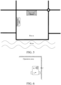
FIG. 5 , a plot m is an approximately rectangular plot divided by a plurality of roads, in which obstacles such as a house and a swimming pool are distributed, and a south side of the plot m is adjacent to a river. - It has been clarified above that the initial map of each plot in the plot database has limited precision. Therefore, in order to improve the map creating precision of the autonomous robot, it is necessary to perform boundary detection on the initial boundary to optimize the initial boundary according to the measured boundary. In some embodiments of this specification, based on data provided by a boundary detection apparatus (such as a white circle mark in
FIG. 6 ), a positioning apparatus (such as a black triangle mark inFIG. 6 ) configured for the autonomous robot, and the like, the measuredboundary acquisition module 22 may cause the autonomous robot to perform boundary detection along the initial boundary of the operation area (as shown inFIG. 6 ) to acquire the measured boundary. In some embodiments, the boundary detection apparatus may include, but is not limited to, one or more of a visual sensor, a multispectral sensor, a capacitive proximity sensor, or a radar sensor. In order to cause the autonomous robot to be applicable to the boundary detection in various operating conditions, the visual sensor (or a combination of the visual sensor and other boundary sensors) is a better choice. - For ease of understanding, the boundary detection process of the measured
boundary acquisition module 22 is described below by using the autonomous robot performing the boundary detection along the initial boundary as an example. It should be noted that, the expression "along the initial boundary" in this specification may mean that the autonomous robot moves close to the initial boundary in the operation area, and an overall trend of a movement trajectory of the autonomous robot is along the initial boundary. In addition, the autonomous robot may shut down a job actuator thereof during the boundary detection, to improve safety of the boundary detection. For example, an intelligent lawn mower is used as an example. A cutter head may be turned off during the boundary detection. - In some embodiments of this specification, the measured
boundary acquisition module 22 may determine, according to detection data collected by the boundary detection apparatus of the autonomous robot, whether a boundary point is detected. For example, an intelligent lawn mower is used as an example. The operation area of the intelligent lawn mower is usually grass, and a road, a river, a fence, a wall, or the like is generally at an edge of the grass. Therefore, it may be determined, by recognizing an image collected by the visual sensor of the intelligent lawn mower as the boundary detection apparatus, whether the boundary point is detected. - When the boundary point is detected, the measured
boundary acquisition module 22 may record a heading angle of the autonomous robot and first coordinates outputted by a positioning apparatus of the autonomous robot at this time, and may determine second coordinates of the boundary point according to the first coordinate, the heading angle, a distance between the positioning apparatus and the boundary detection apparatus, and the detection data. In this way, the measured boundary may be formed according to second coordinates of each detected boundary point. - For example, in the exemplary embodiment shown in
FIG. 7 , a point A is a position where the positioning apparatus of the autonomous robot is located, and a point B is a position where the boundary detection apparatus of the autonomous robot is located. The heading of the autonomous robot is shown by a direction of a dotted line with an arrow inFIG. 7 . At this time, the recorded heading angle of the autonomous robot is θ, and the recorded coordinates of the point A are ( x 0, y 0 ). Since both the positioning apparatus and the boundary detection apparatus are fixed to the autonomous robot in advance, a distance A-B (that is, a length of c inFIG. 7 ) is known. Therefore, coordinates of the point B ( x 1, y 1 ) may be calculated according to the heading angle θ and the coordinates ( x 0, y 0 ) of the point A. The boundary detection apparatus of the autonomous robot may measure a distance BC (that is a length of a inFIG. 7 ) between the boundary detection apparatus and the detected boundary point (that is a point C inFIG. 7 ). For example, when the boundary detection apparatus is a radar sensor, the distance BC may be measured by using the radar sensor. In another example, when the boundary detection apparatus is a single visual sensor, the distance BC may also be measured based on the principle of monocular vision positioning and ranging. Since ∠ABC is known as a right angle, a distance AC (that is, a length of b inFIG. 7 ) may be calculated based on ∠ABC, a side length a, and a side length c. In this way, coordinates ( x 2, y 2 ) of the point C may be calculated according to the following formulas: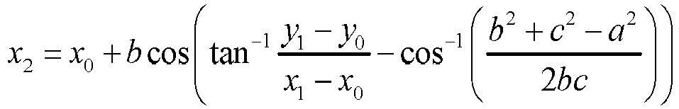
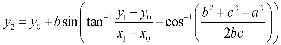
- In this way, the second coordinates of each detected boundary point may be obtained by using the above method, and then the measured boundary may be formed according to the second coordinates of these boundary points.
- In this way, the initial
boundary correction module 23 may correct the initial boundary according to the measured boundary. That is to say, the initialboundary correction module 23 may replace the initial boundary with the measured boundary. Therefore, optimization of the initial map of the operation area is realized, that is, a more precise operation map is obtained. For example, in the exemplary embodiment shown inFIG. 9 , the autonomous robot performs the boundary detection along the initial boundary (refer to a rectangle shown by a thick solid line inFIG. 9 ) of the operation area (that is, a plot m), so that the measured boundary defined by a dotted line inFIG. 9 is obtained. With reference toFIG. 10 , a more precise operation area boundary may be obtained by replacing the initial boundary with the measured boundary (refer to a closed boundary defined by a thick dotted line inFIG. 10 ). - In order to ensure the operation safety of the autonomous robot, in the process of causing the autonomous robot to perform the boundary detection along the initial boundary, the measured
boundary acquisition module 22 may further cause the autonomous robot to maintain a preset safe distance from the initial boundary. - In some cases, part or all of the boundaries of the operation area may be a dangerous area such as a road, a river channel, a swimming pool, a cliff, or the like. In order to prevent the autonomous robot from entering the dangerous area, in a process of causing the autonomous robot to perform the boundary detection along the initial boundary, the measured
boundary acquisition module 22 may cause the autonomous robot to maintain a slightly larger safe distance (for example, 30% larger than a default safe distance) from a dangerous boundary segment in the initial boundary, for example, as shown by d2 inFIG. 8 . The dangerous boundary segment may be defined as a boundary segment adjacent to the dangerous area in the initial boundary. - In some other cases, part or all of the boundaries of the operation area may also be a non-dangerous area such as a fence, a wall, and the like. Therefore, under the premise of ensuring the operation safety of the autonomous robot, in order to take into account the operation coverage of the autonomous robot, for the non-dangerous boundary segment in the initial boundary, in the process of causing the autonomous robot to perform the boundary detection along the initial boundary, the measured
boundary acquisition module 22 may cause the autonomous robot to maintain a slightly small safe distance (for example, smaller than a default safe distance) from the non-dangerous boundary segment, for example, as shown by d1 inFIG. 8 . The non-dangerous boundary segment may be defined as a boundary segment adjacent to the non-dangerous area in the initial boundary, or a boundary segment not adjacent to the dangerous area in the initial boundary. - In some embodiments of this specification, the dangerous area at the boundary of the operation area may be automatically determined by the measured
boundary acquisition module 22 through image recognition, or may be specified by the user, which may be specifically determined as required and is not limited in this specification. The measuredboundary acquisition module 22 may automatically set a safe distance for the dangerous area and the non-dangerous area after determining the dangerous area and the non-dangerous area. - In some embodiments of this specification, in order to further improve the safety of the boundary detection, in the process of causing the autonomous robot to perform the boundary detection along the initial boundary, the measured
boundary acquisition module 22 may further determine whether a to-be-detected boundary segment is the dangerous boundary segment, so as to facilitate on-site manual monitoring of the dangerous boundary segment. Since the dangerous boundary segment and the non-dangerous boundary segment in the initial boundary have been divided before the boundary detection is performed, based on the division result, the measuredboundary acquisition module 22 may determine whether the to-be-detected boundary segment is the dangerous boundary segment. - In some embodiments of this specification, when the to-be-detected boundary segment is the dangerous boundary segment, the measured
boundary acquisition module 22 may further determine whether a detection site is equipped with manual monitoring. When it is determined that the detection site is equipped with the manual monitoring, the measuredboundary acquisition module 22 may cause the autonomous robot to start or continue the boundary detection. When it is determined that the detection site is not equipped with the manual monitoring, the measuredboundary acquisition module 22 stops the autonomous robot, and may further give an alarm, so as to further improve the safety of the boundary detection of the autonomous robot. - In some embodiments of this specification, the measured
boundary acquisition module 22 may determine, in any suitable manner, whether the detection site is equipped with the manual monitoring, which is not limited in this specification and may be specifically selected as required. For example, in some embodiments, it may be determined, depending on whether a wireless communication module of the autonomous robot receives a wireless signal transmitted by a specified device, whether the detection site is equipped with the manual monitoring. The specified device is carried by on-site monitoring personnel, and may continuously transmit wireless signals to the outside. Therefore, when the wireless signal transmitted by the specified device is received, it may be inferred that the detection site is equipped with the manual monitoring. The wireless signal may be, for example, Bluetooth, Wi-Fi, or the like. In another example, it may further be determined, depending on whether an imaging detector of the autonomous robot detects a human body signal within a specified detection radius, whether the detection site is equipped with the manual monitoring. The imaging detector may be, for example, an infrared thermal imaging detector, an imaging radar, or the like. - The foregoing specified device may be any portable device having the foregoing function, for example, including but not limited to, a smart phone, a tablet computer, a notebook computer, a digital assistant, an intelligent wearable device, or the like.
- For the convenience of description, the above apparatus or module is divided into various units by function for description respectively. Certainly, functions of each unit may be implemented in one or more pieces of software and/or hardware during implementation of this specification.
- Corresponding to the foregoing map creating apparatus for an autonomous robot, this specification further provides a map creating method for an autonomous robot. Referring to
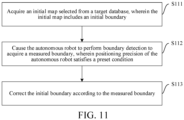
FIG. 11 , the map creating method for an autonomous robot according to some embodiments of this specification may include the following steps. - S111: Acquire an initial map selected from a target database, wherein the initial map includes an initial boundary.
- S112: Cause the autonomous robot to perform boundary detection to acquire a measured boundary, wherein positioning precision of the autonomous robot satisfies a preset condition.
- S113: Correct the initial boundary according to the measured boundary.
- In the map creating method for an autonomous robot according to some embodiments of this specification, the acquiring an initial map selected from a target database may include:
- sending, to a server, a plot selection request carrying plot identification information; and
- receiving a plot selection response carrying a plot map, and using the plot map as the initial map, wherein the plot map is obtained by matching from a plot database by the server according to the plot identification information.
- In the map creating method for an autonomous robot according to some embodiments of this specification, the plot identification information may include any of the following:
- an identifier of a plot; or
- a location address corresponding to the plot.
- In the map creating method for an autonomous robot according to some embodiments of this specification, the acquiring an initial map selected from a target database may include:
receiving an initial map sent by a third party, wherein the initial map is selected from the plot database by the third party. - In the map creating method for an autonomous robot according to some embodiments of this specification, the acquiring an initial map selected from a target database may further include:
receiving an initial map sent by a third party, wherein the initial map is selected from an electronic map by the third party. - In the map creating method for an autonomous robot according to some embodiments of this specification, the causing the autonomous robot to perform boundary detection may include:
- determining, according to detection data collected by a boundary detection apparatus of the autonomous robot, whether a boundary point is detected;
- recording a heading angle of the autonomous robot and first coordinates outputted by a positioning apparatus of the autonomous robot at this time when the boundary point is detected;
- determining second coordinates of the boundary point according to the first coordinates, the heading angle, a distance between the positioning apparatus and the boundary detection apparatus, and the detection data; and
- forming the measured boundary according to second coordinates of each detected boundary point.
- In the map creating method for an autonomous robot according to some embodiments of this specification, the boundary detection apparatus includes a visual sensor.
- The map creating method for an autonomous robot according to some embodiments of this specification may further include:
causing the autonomous robot to maintain a preset safe distance from the initial boundary in the process of causing the autonomous robot to perform the boundary detection. - In the map creating method for an autonomous robot according to some embodiments of this specification, the causing the autonomous robot to maintain a preset safe distance from the initial boundary may include:
causing the autonomous robot to maintain a first safe distance from a dangerous boundary segment in the initial boundary. - In the map creating method for an autonomous robot according to some embodiments of this specification, the causing the autonomous robot to maintain a preset safe distance from the initial boundary may further include:
causing the autonomous robot to maintain a second safe distance from a non-dangerous boundary segment in the initial boundary, where the second safe distance is less than the first safe distance. - The map creating method for an autonomous robot according to some embodiments of this specification may further include:
- determining, in the process of causing the autonomous robot to perform the boundary detection, whether a to-be-detected boundary segment is the dangerous boundary segment;
- determining whether a detection site is equipped with manual monitoring when the to-be-detected boundary segment is the dangerous boundary segment; and
- causing the autonomous robot to start or continue the boundary detection when it is determined that the detection site is equipped with the manual monitoring.
- The map creating method for an autonomous robot according to some embodiments of this specification may further include:
stopping the autonomous robot when it is determined that the detection site is not equipped with the manual monitoring. - The map creating method for an autonomous robot according to some embodiments of this specification may further include:
causing the autonomous robot to start or continue the boundary detection when the to-be-detected boundary segment is a non-dangerous boundary segment. - In the map creating method for an autonomous robot according to some embodiments of this specification, the determining whether a detection site is equipped with manual monitoring may include any one or more of the following:
- determining, depending on whether a wireless communication module of the autonomous robot receives a wireless signal transmitted by a specified device, whether the detection site is equipped with the manual monitoring, wherein the specified device is carried by on-site monitoring personnel; or
- determining, depending on whether an imaging detector of the autonomous robot detects a human body signal within a specified detection radius, whether the detection site is equipped with the manual monitoring.
- In the map creating method for an autonomous robot according to some embodiments of this specification, the correcting the initial boundary according to the measured boundary may include:
replacing the initial boundary with the measured boundary. - Although the process flow described above includes a plurality of operations in a particular order, it should be clearly understood that these processes may include more or fewer operations. These operations may be performed sequentially or in parallel (for example, using a parallel processor or a multi-threaded environment).
- This specification is described according to flowcharts and/or block diagrams of the method, the device (system), and the computer program product according to the embodiments of this specification. It should be understood that each process and/or block in the flowcharts and/or block diagrams, and a combination of the process and/or the block in the flowcharts and/or block diagrams can be realized by computer program instructions. These computer program instructions may be provided to a processor of a general-purpose computer, a special-purpose computer, an embedded processing machine, or other programmable data processing devices to generate a machine, so that execution of the instructions by the processor of the computer or other programmable data processing devices generates an apparatus for implementing functions specified in one or more processes of the flowcharts and/or one or more blocks of the block diagrams.
- These computer program instructions may also be stored in a computer-readable storage that can direct a computer or other programmable data processing devices to operate in a specific manner, so that the instructions stored in the computer-readable storage produce a product including an instruction apparatus. The instruction apparatus implements the functions specified in one or more processes of the flowchart and/or one or more blocks of the block diagram.
- These computer program instructions may also be loaded onto a computer or other programmable data processing devices, so that a series of operating steps are performed on the computer or other programmable devices to generate a computer-implemented process, and the instructions executed on the computer or other programmable devices provide steps for implementing the functions specified in one or more processes of the flowchart and/or one or more blocks of the block diagram.
- In a typical configuration, a computing device includes one or more processors (CPU), an input/output interface, a network interfaces, and a memory.
- The memory may include forms such as a volatile memory in a computer-readable medium, a random access memory (RAM), and/or a non-volatile memory, for example, a read only memory (ROM) or a flash memory (flash RAM). The memory is an example of the computer-readable medium.
- The computer-readable medium includes both permanent and non-permanent, removable and non-removable media, and information storage may be implemented by using any method or technology. The information may be computer-readable instructions, a data structure, a module of a program, or other data. An example of the computer storage medium includes, but is not limited to, a phase-change memory (PRAM), a static random access memory (SRAM), a dynamic random access memory (DRAM), other types of random access memory (RAM), a read-only memory (ROM), an electrically erasable programmable read-only memory (EEPROM), a flash memory or other memory technologies, a compact disc read-only memory (CD-ROM), a digital versatile disc (DVD) or other optical storage, a magnetic tape cassette, a magnetic disk storage or other magnetic storage devices, or any other non-transmission media that may be configured to store information accessible by a computing device. As defined herein, the computer-readable medium does not include transitory computer-readable media, such as a modulated data signal and a carrier.
- It should also be noted that the terms "include", "comprise", and any other variants mean to cover the non-exclusive inclusion. Thereby, the process, method, or device that includes a series of elements not only include those elements, but also include other elements not clearly listed, or include the inherent elements of the process, method, and device. Unless otherwise specified, an element limited by "include a/an ..." does not exclude other same elements existing in the process, the method, or the device that includes the element.
- Those skilled in the art should understand that the embodiments of this specification may be provided as a method, a system, or a computer program product. Therefore, this specification may take the form of a complete hardware embodiment, a complete software embodiment, or an embodiment combining software and hardware. Moreover, this specification may be in the form of a computer program product implemented on one or more computer-usable storage media (including, but not limited to, a disk storage, a CD-ROM, an optical storage, and the like) containing computer-usable program code therein.
- This specification may be described in a general context of computer-executable instructions executed by a computer, for example, a program module. Generally, the program module includes a routine, a program, an object, an assembly, a data structure, and the like that perform a particular task or implement a particular abstract data type. This specification may also be practiced in distributed computing environments. In these distributed computing environments, a task is performed by a remote processing device connected by a communication network. In the distributed computing environment, the program module may be located in local and remote computer storage media including a storage device.
- Each embodiment in this specification is described in a progressive manner, and same and similar parts between the various embodiments may be referred to each other. Each embodiment focuses on a difference from other embodiments. In particular, for a system embodiment, since the system embodiment is basically similar to the method embodiment, the description is relatively simple. For related parts, refer to the partial description of the method embodiment.
Claims (15)
- A map creating method for an autonomous robot (100), comprising:acquiring (S111) an initial map selected from a target database, wherein the initial map comprises an initial boundary;causing (S112) the autonomous robot to perform boundary detection to acquire a measured boundary, wherein positioning precision of the autonomous robot satisfies a preset condition; andcorrecting (S113) the initial boundary according to the measured boundary.
- The map creating method for an autonomous robot according to claim 1, wherein the acquiring an initial map selected from a target database comprises:sending, to a server, a plot selection request carrying plot identification information; andreceiving a plot selection response carrying a plot map, and using the plot map as the initial map, wherein the plot map is obtained by matching from a plot database by the server according to the plot identification information.
- The map creating method for an autonomous robot according to claim 1, wherein the acquiring an initial map selected from a target database comprises:
receiving an initial map sent by a third party, wherein the initial map is selected from the plot database or an electronic map by the third party. - The map creating method for an autonomous robot according to claim 1, wherein the causing the autonomous robot to perform boundary detection comprises:determining, according to detection data collected by a boundary detection apparatus of the autonomous robot, whether a boundary point is detected;recording a heading angle of the autonomous robot and first coordinates outputted by a positioning apparatus of the autonomous robot at this time when the boundary point is detected;determining second coordinates of the boundary point according to the first coordinates, the heading angle, a distance between the positioning apparatus and the boundary detection apparatus, and the detection data; andforming the measured boundary according to second coordinates of each detected boundary point.
- The map creating method for an autonomous robot according to claim 1, further comprising:causing the autonomous robot to maintain a preset safe distance from the initial boundary in the process of causing the autonomous robot to perform the boundary detection;wherein the causing the autonomous robot to maintain a preset safe distance from the initial boundary comprises: causing the autonomous robot to maintain a first safe distance from a dangerous boundary segment in the initial boundary; andcausing the autonomous robot to maintain a second safe distance from a non-dangerous boundary segment in the initial boundary, wherein the second safe distance is less than the first safe distance.
- The map creating method for an autonomous robot according to claim 5, further comprising:determining, in the process of causing the autonomous robot to perform the boundary detection, whether a to-be-detected boundary segment is the dangerous boundary segment;determining whether a detection site is equipped with manual monitoring when the to-be-detected boundary segment is the dangerous boundary segment; andcausing the autonomous robot to start or continue the boundary detection when it is determined that the detection site is equipped with the manual monitoring; andstopping the autonomous robot when it is determined that the detection site is not equipped with the manual monitoring.
- The map creating method for an autonomous robot according to claim 6, wherein the determining whether a detection site is equipped with manual monitoring comprises any one or more of the following:determining, depending on whether a wireless communication module of the autonomous robot receives a wireless signal transmitted by a specified device, whether the detection site is equipped with the manual monitoring, wherein the specified device is carried by on-site monitoring personnel; ordetermining, depending on whether an imaging detector of the autonomous robot detects a human body signal within a specified detection radius, whether the detection site is equipped with the manual monitoring.
- The map creating method for an autonomous robot according to claim 1, wherein the correcting the initial boundary according to the measured boundary comprises:
replacing the initial boundary with the measured boundary. - A map creating apparatus for an autonomous robot (100), comprising:an initial boundary acquisition module (21), configured to acquire an initial map selected from a target database, wherein the initial map comprises an initial boundary;a measured boundary acquisition module (22), configured to cause the autonomous robot to perform boundary detection to acquire a measured boundary, wherein positioning precision of the autonomous robot satisfies a preset condition; andan initial boundary correction module (23), configured to correct the initial boundary according to the measured boundary.
- The map creating apparatus for an autonomous robot according to claim 9, wherein the acquisition of the initial map selected from the target database comprises:sending, to a server, a plot selection request carrying plot identification information; andreceiving a plot selection response carrying a plot map, and using the plot map as the initial map, wherein the plot map is obtained by matching from a plot database by the server according to the plot identification information.
- The map creating apparatus for an autonomous robot according to claim 9, wherein the acquisition of the initial map selected from the target database comprises:
receiving an initial map sent by a third party, wherein the initial map is selected from the plot database or an electronic map by the third party. - The map creating apparatus for an autonomous robot according to claim 9, wherein the causing of the autonomous robot to perform boundary detection comprises:determining, according to detection data collected by a boundary detection apparatus of the autonomous robot, whether a boundary point is detected;recording a heading angle of the autonomous robot and first coordinates outputted by a positioning apparatus of the autonomous robot at this time when the boundary point is detected;determining second coordinates of the boundary point according to the first coordinates, the heading angle, a distance between the positioning apparatus and the boundary detection apparatus, and the detection data; andforming the measured boundary according to second coordinates of each detected boundary point.
- The map creating apparatus for an autonomous robot according to claim 9, wherein the measured boundary acquisition module is further configured to:cause the autonomous robot to maintain a preset safe distance from the initial boundary in the process of causing the autonomous robot to perform the boundary detection;wherein the causing the autonomous robot to maintain a preset safe distance from the initial boundary comprises: causing the autonomous robot to maintain a first safe distance from a dangerous boundary segment in the initial boundary; andcausing the autonomous robot to maintain a second safe distance from a non-dangerous boundary segment in the initial boundary, wherein the second safe distance is less than the first safe distance.
- The map creating apparatus for an autonomous robot according to claim 13, wherein the measured boundary acquisition module is further configured to:determine, in the process of causing the autonomous robot to perform the boundary detection, whether a to-be-detected boundary segment is the dangerous boundary segment;determine whether a detection site is equipped with manual monitoring when the to-be-detected boundary segment is the dangerous boundary segment; andcause the autonomous robot to start or continue the boundary detection when it is determined that the detection site is equipped with the manual monitoring; andstop the autonomous robot when it is determined that the detection site is not equipped with the manual monitoring.
- An autonomous robot (100), configured with the map creating apparatus according to any of claims 9 to 14.
Applications Claiming Priority (2)
| Application Number | Priority Date | Filing Date | Title |
|---|---|---|---|
| CN202010002699.0A CN113138593A (en) | 2020-01-02 | 2020-01-02 | Autonomous robot map creation method, device, equipment and storage medium |
| PCT/CN2020/128027 WO2021135658A1 (en) | 2020-01-02 | 2020-11-11 | Map creating method and apparatus for autonomous robot, device, and storage medium |
Publications (3)
| Publication Number | Publication Date |
|---|---|
| EP4086722A1 EP4086722A1 (en) | 2022-11-09 |
| EP4086722A4 EP4086722A4 (en) | 2023-09-13 |
| EP4086722B1 true EP4086722B1 (en) | 2024-12-04 |
Family
ID=76686418
Family Applications (1)
| Application Number | Title | Priority Date | Filing Date |
|---|---|---|---|
| EP20908702.2A Active EP4086722B1 (en) | 2020-01-02 | 2020-11-11 | Map creating method and apparatus for autonomous robot, device, and storage medium |
Country Status (4)
| Country | Link |
|---|---|
| US (1) | US12393206B2 (en) |
| EP (1) | EP4086722B1 (en) |
| CN (1) | CN113138593A (en) |
| WO (1) | WO2021135658A1 (en) |
Families Citing this family (5)
| Publication number | Priority date | Publication date | Assignee | Title |
|---|---|---|---|---|
| CN116071232A (en) * | 2022-12-20 | 2023-05-05 | 深圳市智目科技有限公司 | A method, device and related equipment for generating pet activity range |
| CN116869424A (en) * | 2023-04-28 | 2023-10-13 | 深圳银星智能集团股份有限公司 | Robot control method and device, computer readable storage medium and robot |
| DE102023208365A1 (en) * | 2023-08-31 | 2025-03-06 | Robert Bosch Gesellschaft mit beschränkter Haftung | Method for determining a boundary of a work area for a mobile device |
| CN121209486A (en) * | 2024-06-26 | 2025-12-26 | 浙江白马科技有限公司 | An autonomous operating device and its control method, apparatus and storage medium |
| CN120355814B (en) * | 2025-06-20 | 2025-09-12 | 深圳库犸科技有限公司 | Automatic drawing construction method and device |
Citations (6)
| Publication number | Priority date | Publication date | Assignee | Title |
|---|---|---|---|---|
| US8649930B2 (en) | 2009-09-17 | 2014-02-11 | Agjunction Llc | GNSS integrated multi-sensor control system and method |
| WO2016102141A1 (en) | 2014-12-24 | 2016-06-30 | Husqvarna Ab | Improved navigation for a robotic work tool |
| EP3167700A1 (en) | 2015-11-13 | 2017-05-17 | Robert Bosch Gmbh | Autonomous work device |
| CN107239074A (en) | 2016-03-29 | 2017-10-10 | 苏州宝时得电动工具有限公司 | Automatic working system and its map method for building up of working region |
| CN109491397A (en) | 2019-01-14 | 2019-03-19 | 深圳市傲基电子商务股份有限公司 | Mowing robot and mowing area defining method thereof |
| WO2021014117A1 (en) | 2019-07-22 | 2021-01-28 | Kingdom Technologies Ltd | Robotic lawn mower control |
Family Cites Families (40)
| Publication number | Priority date | Publication date | Assignee | Title |
|---|---|---|---|---|
| IL113913A (en) | 1995-05-30 | 2000-02-29 | Friendly Machines Ltd | Navigation method and system |
| JP2007256149A (en) * | 2006-03-24 | 2007-10-04 | Clarion Co Ltd | Navigation system and map display method |
| KR100843085B1 (en) * | 2006-06-20 | 2008-07-02 | 삼성전자주식회사 | Grid map preparation method and device of mobile robot and method and device for area separation |
| CA2854274C (en) * | 2011-11-09 | 2015-10-13 | Hitachi, Ltd. | Autonomous travel system |
| JP6132659B2 (en) * | 2013-02-27 | 2017-05-24 | シャープ株式会社 | Ambient environment recognition device, autonomous mobile system using the same, and ambient environment recognition method |
| CN104345734A (en) | 2013-08-07 | 2015-02-11 | 苏州宝时得电动工具有限公司 | Automatic working system, automatic walking equipment and control method thereof |
| EP2848892B1 (en) * | 2013-09-13 | 2017-12-27 | Elektrobit Automotive GmbH | Technique for correcting digitized map data |
| GB201419883D0 (en) | 2014-11-07 | 2014-12-24 | F Robotics Acquisitions Ltd | Domestic robotic system and method |
| CN105652864A (en) * | 2014-11-14 | 2016-06-08 | 科沃斯机器人有限公司 | Map construction method utilizing mobile robot and work method utilizing map |
| US10691958B1 (en) * | 2015-07-30 | 2020-06-23 | Ambarella International Lp | Per-lane traffic data collection and/or navigation |
| RU2702850C1 (en) * | 2015-09-30 | 2019-10-11 | Ниссан Мотор Ко., Лтд. | Method of motion control and movement control device |
| US10496262B1 (en) * | 2015-09-30 | 2019-12-03 | AI Incorporated | Robotic floor-cleaning system manager |
| US11449061B2 (en) * | 2016-02-29 | 2022-09-20 | AI Incorporated | Obstacle recognition method for autonomous robots |
| CN105843228B (en) * | 2016-04-13 | 2018-07-13 | 上海物景智能科技有限公司 | A map sharing method and system for a cleaning robot |
| CN106530946A (en) * | 2016-11-30 | 2017-03-22 | 北京贝虎机器人技术有限公司 | Indoor map editing method and device |
| WO2018226428A2 (en) * | 2017-06-09 | 2018-12-13 | MiLegacy, LLC | Management of a media archive representing personal modular memories |
| US10007269B1 (en) * | 2017-06-23 | 2018-06-26 | Uber Technologies, Inc. | Collision-avoidance system for autonomous-capable vehicle |
| US11274929B1 (en) * | 2017-10-17 | 2022-03-15 | AI Incorporated | Method for constructing a map while performing work |
| JP6929190B2 (en) | 2017-10-18 | 2021-09-01 | 株式会社クボタ | Work area determination system for autonomous traveling work machines |
| DE102017218917A1 (en) * | 2017-10-24 | 2019-04-25 | Robert Bosch Gmbh | Monitoring device, industrial plant, monitoring method and computer program |
| CN108106616B (en) * | 2017-12-13 | 2020-07-28 | 深圳市艾特智能科技有限公司 | Method and system for self-building navigation map and intelligent equipment |
| KR102024094B1 (en) * | 2017-12-21 | 2019-09-23 | 엘지전자 주식회사 | A moving-robot using artificial intelligence and a controlling method for the same |
| WO2019232803A1 (en) * | 2018-06-08 | 2019-12-12 | 珊口(深圳)智能科技有限公司 | Mobile control method, mobile robot and computer storage medium |
| CN116578068A (en) * | 2018-06-15 | 2023-08-11 | 科沃斯机器人股份有限公司 | Robot positioning method, robot and storage medium |
| CN108908331B (en) * | 2018-07-13 | 2022-04-22 | 哈尔滨工业大学(深圳) | Obstacle avoidance method and system for super-redundant flexible robot and computer storage medium |
| US20200050205A1 (en) * | 2018-08-07 | 2020-02-13 | Cnh Industrial America Llc | System and method for updating a mapped area |
| CN108873912A (en) * | 2018-08-21 | 2018-11-23 | 深圳乐动机器人有限公司 | Management map method, apparatus, computer equipment and storage medium |
| DE102018214962A1 (en) * | 2018-09-04 | 2020-03-05 | Robert Bosch Gmbh | Method and device for securing an overtaking process of a vehicle hitting a bicycle |
| CN109344214A (en) * | 2018-09-07 | 2019-02-15 | 北京云迹科技有限公司 | Management map method and robot |
| CN109682368B (en) * | 2018-11-30 | 2021-07-06 | 上海肇观电子科技有限公司 | Robot and map construction method, positioning method, electronic device, storage medium |
| CN109984684B (en) * | 2019-04-11 | 2021-04-27 | 云鲸智能科技(东莞)有限公司 | Cleaning control method, cleaning control device, cleaning robot and storage medium |
| KR102275300B1 (en) * | 2019-07-05 | 2021-07-08 | 엘지전자 주식회사 | Moving robot and control method thereof |
| KR102302575B1 (en) * | 2019-07-16 | 2021-09-14 | 엘지전자 주식회사 | Moving robot and control method thereof |
| US11383704B2 (en) * | 2019-08-16 | 2022-07-12 | Ford Global Technologies, Llc | Enhanced vehicle operation |
| CN110609550B (en) * | 2019-09-11 | 2021-02-23 | 珠海市一微半导体有限公司 | Method for preventing robot from colliding with charging seat |
| CN110567467A (en) * | 2019-09-11 | 2019-12-13 | 北京云迹科技有限公司 | map construction method and device based on multiple sensors and storage medium |
| CN110568860A (en) * | 2019-09-17 | 2019-12-13 | 深圳市道通智能航空技术有限公司 | Return-to-home method, device and unmanned aerial vehicle for an unmanned aerial vehicle |
| KR20210039869A (en) * | 2019-10-02 | 2021-04-12 | 삼성전자주식회사 | Moving robot and controlling method thereof |
| JP7358896B2 (en) * | 2019-10-09 | 2023-10-11 | 株式会社Jvcケンウッド | Vehicle electronic equipment and control method |
| US11327492B2 (en) * | 2019-12-03 | 2022-05-10 | Mitsubishi Electric Research Laboratories, Inc. | Adaptive control of autonomous or semi-autonomous vehicle |
-
2020
- 2020-01-02 CN CN202010002699.0A patent/CN113138593A/en active Pending
- 2020-11-11 WO PCT/CN2020/128027 patent/WO2021135658A1/en not_active Ceased
- 2020-11-11 EP EP20908702.2A patent/EP4086722B1/en active Active
- 2020-11-11 US US17/790,695 patent/US12393206B2/en active Active
Patent Citations (6)
| Publication number | Priority date | Publication date | Assignee | Title |
|---|---|---|---|---|
| US8649930B2 (en) | 2009-09-17 | 2014-02-11 | Agjunction Llc | GNSS integrated multi-sensor control system and method |
| WO2016102141A1 (en) | 2014-12-24 | 2016-06-30 | Husqvarna Ab | Improved navigation for a robotic work tool |
| EP3167700A1 (en) | 2015-11-13 | 2017-05-17 | Robert Bosch Gmbh | Autonomous work device |
| CN107239074A (en) | 2016-03-29 | 2017-10-10 | 苏州宝时得电动工具有限公司 | Automatic working system and its map method for building up of working region |
| CN109491397A (en) | 2019-01-14 | 2019-03-19 | 深圳市傲基电子商务股份有限公司 | Mowing robot and mowing area defining method thereof |
| WO2021014117A1 (en) | 2019-07-22 | 2021-01-28 | Kingdom Technologies Ltd | Robotic lawn mower control |
Non-Patent Citations (3)
| Title |
|---|
| DENNIS SPRUTE; ROBIN RASCH; KLAUS T\"ONNIES; MATTHIAS K\"ONIG: "A Framework for Interactive Teaching of Virtual Borders to Mobile Robots", ARXIV.ORG, CORNELL UNIVERSITY LIBRARY, 201 OLIN LIBRARY CORNELL UNIVERSITY ITHACA, NY 14853, 16 February 2017 (2017-02-16), 201 Olin Library Cornell University Ithaca, NY 14853 , XP081274078, DOI: 10.1109/ROMAN.2017.8172453 |
| MIELLE MALCOLM, MAGNUSSON MARTIN, LILIENTHAL ACHIM J.: "The Auto-Complete Graph: Merging and Mutual Correction of Sensor and Prior Maps for SLAM", ROBOTICS, vol. 8, no. 40, 29 May 2019 (2019-05-29), pages 1 - 21, XP055866920, DOI: 10.3390/robotics8020040 |
| PATTERSON ALBERT E., YUAN YANG, NORRIS WILLIAM R.: "Development of User-Integrated Semi-Autonomous Lawn Mowing Systems: A Systems Engineering Perspective and Proposed Architecture", CENTER FOR INTEGRATED BREEDING RESEARCH (CIBREED), GEORG-AUGUST UNIVERSITY, ALBRECHT-THAER-WEG 3, 37075 GÖTTINGEN, GERMANY, MDPI AG, vol. 1, no. 3, pages 453 - 474, XP093308797, ISSN: 2624-7402, DOI: 10.3390/agriengineering1030033 |
Also Published As
| Publication number | Publication date |
|---|---|
| US12393206B2 (en) | 2025-08-19 |
| EP4086722A4 (en) | 2023-09-13 |
| CN113138593A (en) | 2021-07-20 |
| WO2021135658A1 (en) | 2021-07-08 |
| US20240192704A1 (en) | 2024-06-13 |
| EP4086722A1 (en) | 2022-11-09 |
Similar Documents
| Publication | Publication Date | Title |
|---|---|---|
| EP4086722B1 (en) | Map creating method and apparatus for autonomous robot, device, and storage medium | |
| WO2021164738A1 (en) | Area division and path forming method and apparatus for self-moving device and automatic working system | |
| US20210255638A1 (en) | Area Division and Path Forming Method and Apparatus for Self-Moving Device and Automatic Working System | |
| Wang et al. | Intelligent vehicle self-localization based on double-layer features and multilayer LIDAR | |
| EP3698618B1 (en) | Smart lawn mowing system | |
| CN103472823B (en) | A kind of grating map creating method of intelligent robot | |
| US20220264793A1 (en) | Robotic lawn mower control | |
| CN111240322B (en) | Determination method and motion control method of working starting point of robot movement limit frame | |
| CN108445912A (en) | A kind of plant protection drone flight control system | |
| EP3761141B1 (en) | Method for mapping a working area of a mobile device | |
| CN112230256A (en) | Autonomous robot, positioning calibration method and device thereof, and storage medium | |
| WO2023217231A1 (en) | Operation boundary generation method, operation control method, equipment, and storage medium | |
| WO2024055855A1 (en) | Autonomous mobile device and method for controlling the same, and computer readable storage medium | |
| CN116700260A (en) | Returning method and device of mowing robot, system and medium of mowing robot | |
| US11951977B1 (en) | Autonomous vehicle panel and post detection | |
| US12245545B1 (en) | Autonomous vehicle site setup | |
| CN114415659A (en) | Robot safety obstacle avoidance method and device, robot and storage medium | |
| CN117570969B (en) | Mower visual positioning method, device, equipment and storage medium | |
| US12193358B1 (en) | Autonomous vehicle site setup | |
| US12240446B1 (en) | Autonomous vehicle panel and post detection | |
| CN109959935A (en) | A map building method, map building device and robot | |
| CN116360458A (en) | A robot behavior planning method, device, equipment and storage medium | |
| CN120836021A (en) | Method and device for controlling self-moving equipment, and self-moving equipment | |
| CN120370902A (en) | Method and system for identifying inside and outside of working area by garden robot | |
| CN120686701A (en) | Automatic orientation control method, device and storage medium of robot |
Legal Events
| Date | Code | Title | Description |
|---|---|---|---|
| STAA | Information on the status of an ep patent application or granted ep patent |
Free format text: STATUS: THE INTERNATIONAL PUBLICATION HAS BEEN MADE |
|
| PUAI | Public reference made under article 153(3) epc to a published international application that has entered the european phase |
Free format text: ORIGINAL CODE: 0009012 |
|
| STAA | Information on the status of an ep patent application or granted ep patent |
Free format text: STATUS: REQUEST FOR EXAMINATION WAS MADE |
|
| 17P | Request for examination filed |
Effective date: 20220728 |
|
| AK | Designated contracting states |
Kind code of ref document: A1 Designated state(s): AL AT BE BG CH CY CZ DE DK EE ES FI FR GB GR HR HU IE IS IT LI LT LU LV MC MK MT NL NO PL PT RO RS SE SI SK SM TR |
|
| DAV | Request for validation of the european patent (deleted) | ||
| DAX | Request for extension of the european patent (deleted) | ||
| A4 | Supplementary search report drawn up and despatched |
Effective date: 20230816 |
|
| RIC1 | Information provided on ipc code assigned before grant |
Ipc: G05D 1/02 20200101AFI20230809BHEP |
|
| TPAC | Observations filed by third parties |
Free format text: ORIGINAL CODE: EPIDOSNTIPA |
|
| P01 | Opt-out of the competence of the unified patent court (upc) registered |
Effective date: 20240312 |
|
| REG | Reference to a national code |
Free format text: PREVIOUS MAIN CLASS: G05D0001020000 Ref country code: DE Ref legal event code: R079 Ref document number: 602020042792 Country of ref document: DE Ipc: G05D0001000000 |
|
| GRAP | Despatch of communication of intention to grant a patent |
Free format text: ORIGINAL CODE: EPIDOSNIGR1 |
|
| STAA | Information on the status of an ep patent application or granted ep patent |
Free format text: STATUS: GRANT OF PATENT IS INTENDED |
|
| RIC1 | Information provided on ipc code assigned before grant |
Ipc: G05D 1/00 20060101AFI20240724BHEP |
|
| INTG | Intention to grant announced |
Effective date: 20240828 |
|
| GRAS | Grant fee paid |
Free format text: ORIGINAL CODE: EPIDOSNIGR3 |
|
| GRAA | (expected) grant |
Free format text: ORIGINAL CODE: 0009210 |
|
| STAA | Information on the status of an ep patent application or granted ep patent |
Free format text: STATUS: THE PATENT HAS BEEN GRANTED |
|
| AK | Designated contracting states |
Kind code of ref document: B1 Designated state(s): AL AT BE BG CH CY CZ DE DK EE ES FI FR GB GR HR HU IE IS IT LI LT LU LV MC MK MT NL NO PL PT RO RS SE SI SK SM TR |
|
| REG | Reference to a national code |
Ref country code: CH Ref legal event code: EP |
|
| REG | Reference to a national code |
Ref country code: DE Ref legal event code: R096 Ref document number: 602020042792 Country of ref document: DE |
|
| REG | Reference to a national code |
Ref country code: IE Ref legal event code: FG4D |
|
| REG | Reference to a national code |
Ref country code: SE Ref legal event code: TRGR |
|
| REG | Reference to a national code |
Ref country code: LT Ref legal event code: MG9D |
|
| REG | Reference to a national code |
Ref country code: NL Ref legal event code: MP Effective date: 20241204 |
|
| PG25 | Lapsed in a contracting state [announced via postgrant information from national office to epo] |
Ref country code: HR Free format text: LAPSE BECAUSE OF FAILURE TO SUBMIT A TRANSLATION OF THE DESCRIPTION OR TO PAY THE FEE WITHIN THE PRESCRIBED TIME-LIMIT Effective date: 20241204 |
|
| PG25 | Lapsed in a contracting state [announced via postgrant information from national office to epo] |
Ref country code: FI Free format text: LAPSE BECAUSE OF FAILURE TO SUBMIT A TRANSLATION OF THE DESCRIPTION OR TO PAY THE FEE WITHIN THE PRESCRIBED TIME-LIMIT Effective date: 20241204 |
|
| PG25 | Lapsed in a contracting state [announced via postgrant information from national office to epo] |
Ref country code: BG Free format text: LAPSE BECAUSE OF FAILURE TO SUBMIT A TRANSLATION OF THE DESCRIPTION OR TO PAY THE FEE WITHIN THE PRESCRIBED TIME-LIMIT Effective date: 20241204 |
|
| PG25 | Lapsed in a contracting state [announced via postgrant information from national office to epo] |
Ref country code: ES Free format text: LAPSE BECAUSE OF FAILURE TO SUBMIT A TRANSLATION OF THE DESCRIPTION OR TO PAY THE FEE WITHIN THE PRESCRIBED TIME-LIMIT Effective date: 20241204 |
|
| PG25 | Lapsed in a contracting state [announced via postgrant information from national office to epo] |
Ref country code: NO Free format text: LAPSE BECAUSE OF FAILURE TO SUBMIT A TRANSLATION OF THE DESCRIPTION OR TO PAY THE FEE WITHIN THE PRESCRIBED TIME-LIMIT Effective date: 20250304 |
|
| PG25 | Lapsed in a contracting state [announced via postgrant information from national office to epo] |
Ref country code: GR Free format text: LAPSE BECAUSE OF FAILURE TO SUBMIT A TRANSLATION OF THE DESCRIPTION OR TO PAY THE FEE WITHIN THE PRESCRIBED TIME-LIMIT Effective date: 20250305 Ref country code: LV Free format text: LAPSE BECAUSE OF FAILURE TO SUBMIT A TRANSLATION OF THE DESCRIPTION OR TO PAY THE FEE WITHIN THE PRESCRIBED TIME-LIMIT Effective date: 20241204 |
|
| PG25 | Lapsed in a contracting state [announced via postgrant information from national office to epo] |
Ref country code: RS Free format text: LAPSE BECAUSE OF FAILURE TO SUBMIT A TRANSLATION OF THE DESCRIPTION OR TO PAY THE FEE WITHIN THE PRESCRIBED TIME-LIMIT Effective date: 20250304 |
|
| PG25 | Lapsed in a contracting state [announced via postgrant information from national office to epo] |
Ref country code: NL Free format text: LAPSE BECAUSE OF FAILURE TO SUBMIT A TRANSLATION OF THE DESCRIPTION OR TO PAY THE FEE WITHIN THE PRESCRIBED TIME-LIMIT Effective date: 20241204 |
|
| REG | Reference to a national code |
Ref country code: AT Ref legal event code: MK05 Ref document number: 1748815 Country of ref document: AT Kind code of ref document: T Effective date: 20241204 |
|
| PG25 | Lapsed in a contracting state [announced via postgrant information from national office to epo] |
Ref country code: SM Free format text: LAPSE BECAUSE OF FAILURE TO SUBMIT A TRANSLATION OF THE DESCRIPTION OR TO PAY THE FEE WITHIN THE PRESCRIBED TIME-LIMIT Effective date: 20241204 |
|
| PG25 | Lapsed in a contracting state [announced via postgrant information from national office to epo] |
Ref country code: PL Free format text: LAPSE BECAUSE OF FAILURE TO SUBMIT A TRANSLATION OF THE DESCRIPTION OR TO PAY THE FEE WITHIN THE PRESCRIBED TIME-LIMIT Effective date: 20241204 |
|
| PG25 | Lapsed in a contracting state [announced via postgrant information from national office to epo] |
Ref country code: IS Free format text: LAPSE BECAUSE OF FAILURE TO SUBMIT A TRANSLATION OF THE DESCRIPTION OR TO PAY THE FEE WITHIN THE PRESCRIBED TIME-LIMIT Effective date: 20250404 |
|
| PG25 | Lapsed in a contracting state [announced via postgrant information from national office to epo] |
Ref country code: PT Free format text: LAPSE BECAUSE OF FAILURE TO SUBMIT A TRANSLATION OF THE DESCRIPTION OR TO PAY THE FEE WITHIN THE PRESCRIBED TIME-LIMIT Effective date: 20250404 |
|
| PG25 | Lapsed in a contracting state [announced via postgrant information from national office to epo] |
Ref country code: EE Free format text: LAPSE BECAUSE OF FAILURE TO SUBMIT A TRANSLATION OF THE DESCRIPTION OR TO PAY THE FEE WITHIN THE PRESCRIBED TIME-LIMIT Effective date: 20241204 |
|
| PG25 | Lapsed in a contracting state [announced via postgrant information from national office to epo] |
Ref country code: RO Free format text: LAPSE BECAUSE OF FAILURE TO SUBMIT A TRANSLATION OF THE DESCRIPTION OR TO PAY THE FEE WITHIN THE PRESCRIBED TIME-LIMIT Effective date: 20241204 Ref country code: AT Free format text: LAPSE BECAUSE OF FAILURE TO SUBMIT A TRANSLATION OF THE DESCRIPTION OR TO PAY THE FEE WITHIN THE PRESCRIBED TIME-LIMIT Effective date: 20241204 |
|
| PG25 | Lapsed in a contracting state [announced via postgrant information from national office to epo] |
Ref country code: SK Free format text: LAPSE BECAUSE OF FAILURE TO SUBMIT A TRANSLATION OF THE DESCRIPTION OR TO PAY THE FEE WITHIN THE PRESCRIBED TIME-LIMIT Effective date: 20241204 |
|
| PG25 | Lapsed in a contracting state [announced via postgrant information from national office to epo] |
Ref country code: CZ Free format text: LAPSE BECAUSE OF FAILURE TO SUBMIT A TRANSLATION OF THE DESCRIPTION OR TO PAY THE FEE WITHIN THE PRESCRIBED TIME-LIMIT Effective date: 20241204 |
|
| PG25 | Lapsed in a contracting state [announced via postgrant information from national office to epo] |
Ref country code: IT Free format text: LAPSE BECAUSE OF FAILURE TO SUBMIT A TRANSLATION OF THE DESCRIPTION OR TO PAY THE FEE WITHIN THE PRESCRIBED TIME-LIMIT Effective date: 20241204 |
|
| REG | Reference to a national code |
Ref country code: DE Ref legal event code: R026 Ref document number: 602020042792 Country of ref document: DE |
|
| PLBI | Opposition filed |
Free format text: ORIGINAL CODE: 0009260 |
|
| PLAX | Notice of opposition and request to file observation + time limit sent |
Free format text: ORIGINAL CODE: EPIDOSNOBS2 |
|
| 26 | Opposition filed |
Opponent name: HUSQVARNA AB Effective date: 20250820 |
|
| PG25 | Lapsed in a contracting state [announced via postgrant information from national office to epo] |
Ref country code: DK Free format text: LAPSE BECAUSE OF FAILURE TO SUBMIT A TRANSLATION OF THE DESCRIPTION OR TO PAY THE FEE WITHIN THE PRESCRIBED TIME-LIMIT Effective date: 20241204 |
|
| PGFP | Annual fee paid to national office [announced via postgrant information from national office to epo] |
Ref country code: GB Payment date: 20251219 Year of fee payment: 6 |
|
| PGFP | Annual fee paid to national office [announced via postgrant information from national office to epo] |
Ref country code: FR Payment date: 20251231 Year of fee payment: 6 |
|
| PLBB | Reply of patent proprietor to notice(s) of opposition received |
Free format text: ORIGINAL CODE: EPIDOSNOBS3 |