EP4086641A1 - Verfahren zur messung des stabilitätsgrades von generator und stromübertragungsleitung und elektrizitätsnetzsteuerungssystem - Google Patents
Verfahren zur messung des stabilitätsgrades von generator und stromübertragungsleitung und elektrizitätsnetzsteuerungssystem Download PDFInfo
- Publication number
- EP4086641A1 EP4086641A1 EP20910113.8A EP20910113A EP4086641A1 EP 4086641 A1 EP4086641 A1 EP 4086641A1 EP 20910113 A EP20910113 A EP 20910113A EP 4086641 A1 EP4086641 A1 EP 4086641A1
- Authority
- EP
- European Patent Office
- Prior art keywords
- stability
- power
- reactive power
- target value
- inductive
- Prior art date
- Legal status (The legal status is an assumption and is not a legal conclusion. Google has not performed a legal analysis and makes no representation as to the accuracy of the status listed.)
- Granted
Links
Images

Classifications
-
- G—PHYSICS
- G01—MEASURING; TESTING
- G01R—MEASURING ELECTRIC VARIABLES; MEASURING MAGNETIC VARIABLES
- G01R21/00—Arrangements for measuring electric power or power factor
- G01R21/133—Arrangements for measuring electric power or power factor by using digital technique
- G01R21/1331—Measuring real or reactive component, measuring apparent energy
-
- G—PHYSICS
- G01—MEASURING; TESTING
- G01R—MEASURING ELECTRIC VARIABLES; MEASURING MAGNETIC VARIABLES
- G01R31/00—Arrangements for testing electric properties; Arrangements for locating electric faults; Arrangements for electrical testing characterised by what is being tested not provided for elsewhere
- G01R31/34—Testing dynamo-electric machines
- G01R31/346—Testing of armature or field windings
-
- H—ELECTRICITY
- H02—GENERATION; CONVERSION OR DISTRIBUTION OF ELECTRIC POWER
- H02J—ELECTRIC POWER NETWORKS; CIRCUIT ARRANGEMENTS OR SYSTEMS FOR SUPPLYING OR DISTRIBUTING ELECTRIC POWER; SYSTEMS FOR STORING ELECTRIC ENERGY
- H02J13/00—Circuit arrangements for providing remote monitoring or remote control of equipment in a power distribution network
- H02J13/12—Monitoring network conditions, e.g. electrical magnitudes or operational status
-
- H—ELECTRICITY
- H02—GENERATION; CONVERSION OR DISTRIBUTION OF ELECTRIC POWER
- H02J—ELECTRIC POWER NETWORKS; CIRCUIT ARRANGEMENTS OR SYSTEMS FOR SUPPLYING OR DISTRIBUTING ELECTRIC POWER; SYSTEMS FOR STORING ELECTRIC ENERGY
- H02J3/00—Circuit arrangements for AC mains or AC distribution networks
- H02J3/001—Arrangements for handling faults or abnormalities, e.g. emergencies or contingencies
- H02J3/0012—Arrangements for handling faults or abnormalities, e.g. emergencies or contingencies characterised by the contingency detection means in AC networks, e.g. using phasor measurement units [PMU], synchrophasors or contingency analysis
-
- H—ELECTRICITY
- H02—GENERATION; CONVERSION OR DISTRIBUTION OF ELECTRIC POWER
- H02J—ELECTRIC POWER NETWORKS; CIRCUIT ARRANGEMENTS OR SYSTEMS FOR SUPPLYING OR DISTRIBUTING ELECTRIC POWER; SYSTEMS FOR STORING ELECTRIC ENERGY
- H02J3/00—Circuit arrangements for AC mains or AC distribution networks
- H02J3/001—Arrangements for handling faults or abnormalities, e.g. emergencies or contingencies
- H02J3/0014—Arrangements for handling faults or abnormalities, e.g. emergencies or contingencies for preventing or reducing power oscillations in networks
-
- H—ELECTRICITY
- H02—GENERATION; CONVERSION OR DISTRIBUTION OF ELECTRIC POWER
- H02J—ELECTRIC POWER NETWORKS; CIRCUIT ARRANGEMENTS OR SYSTEMS FOR SUPPLYING OR DISTRIBUTING ELECTRIC POWER; SYSTEMS FOR STORING ELECTRIC ENERGY
- H02J3/00—Circuit arrangements for AC mains or AC distribution networks
- H02J3/12—Arrangements for adjusting voltage in AC networks by changing a characteristic of the network load
- H02J3/16—Arrangements for adjusting voltage in AC networks by changing a characteristic of the network load by adjustment of reactive power
-
- H—ELECTRICITY
- H02—GENERATION; CONVERSION OR DISTRIBUTION OF ELECTRIC POWER
- H02J—ELECTRIC POWER NETWORKS; CIRCUIT ARRANGEMENTS OR SYSTEMS FOR SUPPLYING OR DISTRIBUTING ELECTRIC POWER; SYSTEMS FOR STORING ELECTRIC ENERGY
- H02J3/00—Circuit arrangements for AC mains or AC distribution networks
- H02J3/38—Arrangements for feeding a single network from two or more generators or sources in parallel; Arrangements for feeding already energised networks from additional generators or sources in parallel
- H02J3/46—Controlling the sharing of generated power between the generators, sources or networks
-
- G—PHYSICS
- G01—MEASURING; TESTING
- G01R—MEASURING ELECTRIC VARIABLES; MEASURING MAGNETIC VARIABLES
- G01R19/00—Arrangements for measuring currents or voltages or for indicating presence or sign thereof
- G01R19/25—Arrangements for measuring currents or voltages or for indicating presence or sign thereof using digital measurement techniques
- G01R19/2513—Arrangements for monitoring electric power systems, e.g. power lines or loads; Logging
-
- G—PHYSICS
- G01—MEASURING; TESTING
- G01R—MEASURING ELECTRIC VARIABLES; MEASURING MAGNETIC VARIABLES
- G01R21/00—Arrangements for measuring electric power or power factor
- G01R21/001—Measuring real or reactive component; Measuring apparent energy
- G01R21/003—Measuring reactive component
-
- G—PHYSICS
- G01—MEASURING; TESTING
- G01R—MEASURING ELECTRIC VARIABLES; MEASURING MAGNETIC VARIABLES
- G01R31/00—Arrangements for testing electric properties; Arrangements for locating electric faults; Arrangements for electrical testing characterised by what is being tested not provided for elsewhere
- G01R31/34—Testing dynamo-electric machines
- G01R31/343—Testing dynamo-electric machines in operation
-
- Y—GENERAL TAGGING OF NEW TECHNOLOGICAL DEVELOPMENTS; GENERAL TAGGING OF CROSS-SECTIONAL TECHNOLOGIES SPANNING OVER SEVERAL SECTIONS OF THE IPC; TECHNICAL SUBJECTS COVERED BY FORMER USPC CROSS-REFERENCE ART COLLECTIONS [XRACs] AND DIGESTS
- Y02—TECHNOLOGIES OR APPLICATIONS FOR MITIGATION OR ADAPTATION AGAINST CLIMATE CHANGE
- Y02E—REDUCTION OF GREENHOUSE GAS [GHG] EMISSIONS, RELATED TO ENERGY GENERATION, TRANSMISSION OR DISTRIBUTION
- Y02E40/00—Technologies for an efficient electrical power generation, transmission or distribution
- Y02E40/30—Reactive power compensation
-
- Y—GENERAL TAGGING OF NEW TECHNOLOGICAL DEVELOPMENTS; GENERAL TAGGING OF CROSS-SECTIONAL TECHNOLOGIES SPANNING OVER SEVERAL SECTIONS OF THE IPC; TECHNICAL SUBJECTS COVERED BY FORMER USPC CROSS-REFERENCE ART COLLECTIONS [XRACs] AND DIGESTS
- Y02—TECHNOLOGIES OR APPLICATIONS FOR MITIGATION OR ADAPTATION AGAINST CLIMATE CHANGE
- Y02E—REDUCTION OF GREENHOUSE GAS [GHG] EMISSIONS, RELATED TO ENERGY GENERATION, TRANSMISSION OR DISTRIBUTION
- Y02E60/00—Enabling technologies; Technologies with a potential or indirect contribution to GHG emissions mitigation
-
- Y—GENERAL TAGGING OF NEW TECHNOLOGICAL DEVELOPMENTS; GENERAL TAGGING OF CROSS-SECTIONAL TECHNOLOGIES SPANNING OVER SEVERAL SECTIONS OF THE IPC; TECHNICAL SUBJECTS COVERED BY FORMER USPC CROSS-REFERENCE ART COLLECTIONS [XRACs] AND DIGESTS
- Y04—INFORMATION OR COMMUNICATION TECHNOLOGIES HAVING AN IMPACT ON OTHER TECHNOLOGY AREAS
- Y04S—SYSTEMS INTEGRATING TECHNOLOGIES RELATED TO POWER NETWORK OPERATION, COMMUNICATION OR INFORMATION TECHNOLOGIES FOR IMPROVING THE ELECTRICAL POWER GENERATION, TRANSMISSION, DISTRIBUTION, MANAGEMENT OR USAGE, i.e. SMART GRIDS
- Y04S10/00—Systems supporting electrical power generation, transmission or distribution
- Y04S10/30—State monitoring, e.g. fault, temperature monitoring, insulator monitoring, corona discharge
Definitions
- the present disclosure relates to stability measuring and controlling methods and systems for a power plant, a transformer substation and a wide area power grid. Specifically, the present disclosure relates to accurate stability calculating and controlling methods for a power plant, a transformer substation and a wide area power grid and optimized controlling systems for stable operation of the power plant, the transformer substation and the wide area power grid, which provide a risk early warning to a power plant, a transformer substation and a wide area power grid with excessive low stability and disturbance risk.
- WAWS Wide area measurement systems
- subsynchronous oscillation monitoring devices shafting torsional vibration monitoring and protection devices and other systems or equipment are used on site to monitor the low-frequency, sub-synchronous or super-synchronous oscillation of the power grid and protect the power grid by tripping.
- the present disclosure proposes optimized stability measuring methods and stability controlling systems for a generator, an electric transmission line, a power plant grid, a transformer substation grid and a wide area power grid, which have the following technical advantages.
- the stability of the power plant grid and the transformer substation grid is improved by optimized control, which can reserve sufficient adjustment space for the automatic stability regulation device in the power plant or the transformer substation, and ensure the automatic stability regulation device in the power plant and the transformer substation to effectively damp the oscillation when the voltage or frequency of the grid changes suddenly, thereby preventing the occurrence of disturbance sources caused by generator overshoot in an accident state.
- Technical measures to improve the stability of the wide area power grid through optimized control can improve dynamic reactive power reserves of the power plant grid and the transformer substation grid, reduce the amplitude of voltage fluctuation in the power plant and the transformer substation during the voltage sudden change, enhance the mutual support of the dynamic reactive power reserves between the power plant and the transformer substation, restore the voltage stability to the greatest extent after the voltage sudden change, and reduce the probability of high and low voltage trips of auxiliary equipment in the power plant and the transformer substation and reduce the probability of high and low voltage off-grid of wind and solar generator sets.
- the present disclosure provides a stability measuring method for a generator, a stability measuring method for an electric transmission line, a power grid controlling system, and details are as follows.
- a stability measuring method for a synchronous generator includes the following steps sequentially:
- the electrical quantities collected in S1 include a stator current signal, a stator voltage signal, an exciting current signal and an exciting voltage signal of the synchronous generator, and a voltage signal of a bus of a power plant.
- a stability measuring method for an electric transmission line includes the following steps sequentially:
- a stability measuring method for a power plant grid includes the following steps sequentially:
- the electrical quantities collected in S51 include a stator current signal, a stator voltage signal, an exciting current signal and an exciting voltage signal of each synchronous generator in the power plant, and a voltage signal of a bus of the power plant.
- a stability measuring method for a transformer substation grid includes the following steps sequentially:
- the electrical quantities collected in S71 include a current signal and a voltage signal of each electric transmission line in the transformer substation, and a voltage signal of a bus of the transformer substation.
- a stability measuring method for a wide area power grid which includes:
- a stability controlling system of a power plant grid which includes: an electrical acquisition device; a monitoring device; a load regulating device; and a high-speed communication network.
- the high-speed communication network is configured to allow communicate a stability measuring and controlling system of the power plant grid with a calculating module of a stability measuring and controlling system of a wide area power grid.
- the load regulating device is configured to regulate a load of a generator.
- the electrical acquisition device and the monitoring device are configured to determine a dynamic reactive power reserve target value, a capacitive dynamic reactive power reserve target value, an inductive dynamic reactive power reserve target value, a capacitive stability, an inductive stability and a stability of a power plant according to the method as described in any embodiment above.
- the monitoring device is configured to select two pairs of synchronous generators for regulation based on operation conditions of all synchronous generators in the power plant if it is determined that the stability of the power plant grid is less than a preset minimum stability.
- the two pairs of synchronous generators are selected by:
- pair of synchronous generators which have the minimum active power deviation rate and the maximum active power deviation rate respectively and the pair of synchronous generators which have the minimum reactive power deviation rate and the maximum reactive power deviation rate respectively are regulated by:
- a total active power and a total reactive power of the power plant are compared with respective total power target values, and power balance regulation to the whole power plant is performed when the following conditions are met:
- the total active power and the total reactive power of the power plant are kept to follow the respective total power target values.
- the preset disclosure provides in embodiments a stability controlling system of a transformer substation grid, which includes: an electrical acquisition device; a monitoring device; a load regulating device; and a high-speed communication network.
- the high-speed communication network is configured to communicate a stability measuring and controlling system of the transformer substation grid with a calculating module of a stability measuring and controlling system of a wide area power grid.
- the load regulating device is configured to regulate a load of an electric transmission line.
- the electrical acquisition device and the monitoring device are configured to determine a dynamic reactive power reserve target value, a capacitive dynamic reactive power reserve target value, an inductive dynamic reactive power reserve target value, a capacitive stability, an inductive stability and a stability of the electric transmission line according to the method as described in any embodiment above.
- the monitoring device is configured to select a pair of electric transmission lines at a power source side which have a minimum active power deviation rate and a maximum active power deviation rate respectively and select a pair of electric transmission lines at the power source side which have a minimum reactive power deviation rate and a maximum reactive power deviation rate respectively for regulation, based on operation conditions of the electric transmission lines, and specifically, the two pairs of electric transmission lines are selected by:
- pair of electric transmission lines at the power source side which have the minimum active power deviation rate and the maximum active power deviation rate respectively and the pair of electric transmission lines at the power source side which have the minimum reactive power deviation rate and the maximum reactive power deviation rate respectively are regulated by:
- a total active power and a total reactive power of the transformer substation are compared with respective total power target values, and power balance regulation to the transformer substation is performed when the following conditions are met:
- the total active power and the total reactive power of the transformer substation are kept to follow the respective total power target values.
- a stability controlling system of a wide area power grid which includes: a stability controlling system of a power plant grid as described in any embodiment above and/or a stability controlling system of a transformer substation grid as described in any embodiment above; a stability calculating module of the wide area power grid; and a high-speed communication network.
- the high-speed communication network is configured to communicate with the stability controlling system of the power plant grid and/or the stability controlling system of the transformer substation grid.
- the stability calculating module of the wide area power grid is configured to calculate a stability of the wide area power grid using a stability measuring method for a wide area power grid as describe, and transmit total power target values of the power plant grid or the transformer substation grid and a regulating instruction of the wide area power grid to the stability controlling system of the power plant grid or the stability controlling system of the transformer substation grid through the high-speed communication network after the regulating instruction is determined.
- the stability calculating module of the wide area power grid determines the regulating instruction of the wide area power grid by:
- the regulation is optimized to equate dynamic reactive power reserve proportions of power plant grids and transformer substation grids in the wide area power grid.
- 1-pivotal transformer substation 2-stability measuring and controlling system for power plant and transformer substation grids; 3-wind power transformer substation; 4-power plant; 5-electric transmission line at a power source side of a transformer substation; 6-wind driven generator; 7-synchronous generator; 8-electric transmission line for a power plant or a transformer substation; 9-wide area power grid stability measuring and controlling module.
- FIG. 1 is schematic module diagram showing composition of an electrical power system.
- the electrical power system there is a wide area power grid, which be composed of several wind power transformer substation grids 3 and several power plant grids 4.
- the wind power transformer substation and the power plant are each installed with a grid stability measuring and controlling system cabinet, which are connected with a stability measuring and controlling module of the wide area power grid via a high-speed communication network.
- stability measuring methods for a generator, an electric transmission line, a transformer substation and a power plant provided in the present disclosure are used to measure the respective stabilities of the generator, the electric transmission line, the transformer substation and the power plant, and controlling systems of a transformer substation grid, a power plant grid and a wide area power grid provided in the present disclosure are used to control the respective grid stabilities.
- problems presented in existing systems such as excessive low stability of the power plant and the transformer substation and undetected disturbance risk, are overcame, and a risk early warning can be given to the abnormal stability of the wide area power grid.
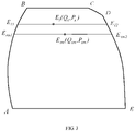
- a curve abcdea is an alarm PQ curve of a synchronous generator, in which a curve ab represents a low excitation limiting curve of the synchronous generator, a curve be represents an active power limiting curve of the synchronous generator, a curve cd represents an overexcitation limiting curve limited by a maximum current and a maximum flux of a generator stator, a curve de represents an overexcitation limiting curve limited by a maximum working voltage and a maximum working current of a working exciter or a standby exciter of the synchronous generator, a maximum excitation voltage and a maximum excitation current of a generator rotor and a maximum excitation flux of the generator together, a curve ea represents a zero active curve of the synchronous generator, which is horizontal.
- a point E 0 (Q, P) represents an operating PQ point of the synchronous generator, where Q represents a reactive power of the synchronous generator, and P represents an active power of the synchronous generator.
- a dynamic reactive power reserve of the synchronous generator is calculated as a length of a segment E 01 E 02 between a left intersection point E 01 of a horizontal line passing through the operating PQ point E 0 of the synchronous generator and the alarm PQ curve of the synchronous generator and a right intersection point E 02 of the horizontal line passing through the operating PQ point E 0 of the synchronous generator and the alarm PQ curve of the synchronous generator.
- a capacitive dynamic reactive power reserve of the synchronous generator is calculated as a length of a segment E 01 E 0 between the left intersection point E 01 of the horizontal line passing through the operating PQ point E 0 of the synchronous generator and the alarm PQ curve of the synchronous generator and the operating PQ point E 0 of the synchronous generator.
- an inductive dynamic reactive power reserve of the synchronous generator is calculated as a length of a segment E 0 E 02 between the right intersection point E 02 of the horizontal line passing through the operating PQ point E 0 of the synchronous generator and the alarm PQ curve of the synchronous generator and the operating PQ point E 0 of the synchronous generator.
- a coordinated PQ point is calculated for each generator based on a total active power and a total reactive power of a power plant, rated parameters of each generator in the power plant and the alarm PQ curve of the generator in accordance with a rule of uniform reserve.
- a point E m (Q m , P m ) represents the coordinated PQ point of the synchronous generator, where Q m represents a reactive power target value of the synchronous generator, and P m represents an active power target value of the synchronous generator.
- a dynamic reactive power reserve target value, a capacitive dynamic reactive power reserve target value, and an inductive dynamic reactive power reserve target value of the synchronous generator may be determined.
- the dynamic reactive power reserve target value of the synchronous generator is calculated as a length of a segment E m1 E m2 between a left intersection point E m1 of a horizontal line passing through the coordinated PQ point E m of the synchronous generator and the alarm PQ curve of the synchronous generator and a right intersection point E m2 of the horizontal line passing through the coordinated PQ point E m of the synchronous generator and the alarm PQ curve of the synchronous generator.
- the capacitive dynamic reactive power reserve target value of the synchronous generator is calculated as a length of a segment E m1 E m between the left intersection point E m1 of the horizontal line passing through the coordinated PQ point E m of the synchronous generator and the alarm PQ curve of the synchronous generator and the coordinated PQ point E m of the synchronous generator.
- the inductive dynamic reactive power reserve target value of the synchronous generator is calculated as a length of a segment E m E m2 between the right intersection point E m2 of the horizontal line passing through the coordinated PQ point E m of the synchronous generator and the alarm PQ curve of the synchronous generator and the coordinated PQ point E m of the synchronous generator.
- the dynamic reactive power reserve target value, the capacitive dynamic reactive power reserve target value and the inductive dynamic reactive power reserve target value of the synchronous generator have different definitions and calculation methods, embodiments of the present disclosure only adopt the above-described calculation methods. It will be appreciated that other calculation methods can also be used for measuring the stability of a generator, an electric transmission line, a transformer substation and a power plant.
- a curve ABCDEA is an alarm PQ curve of an electric transmission line.
- a range enclosed by the ABCDEA curve is a maximum adjustable PQ range allowed by stability automatic regulating devices, such as an automatic excitation regulator (AVR) of a generator of a power plant connected to the electric transmission line, a power system stabilizer (PSS), a sub-synchronous disturbance excitation suppression device, a generator primary frequency adjustment device and the like, comprehensively considering a transmission capacity of the electric transmission line, an output allowed by the power plant connected to the electric transmission line and other factors.
- AVR automatic excitation regulator
- PSS power system stabilizer
- a sub-synchronous disturbance excitation suppression device a generator primary frequency adjustment device and the like
- a point E 1 (Q x , P x ) represents an operating PQ point of the electric transmission line, where Q x represents a reactive power of the electric transmission line, and P x represents an active power of the electric transmission line.
- a dynamic reactive power reserve, a capacitive dynamic reactive power reserve and an inductive dynamic reactive power reserve of the electric transmission line may be calculated according to FIG. 3 .
- the dynamic reactive power reserve of the electric transmission line is calculated as a length of a segment E 11 E 12 between a left intersection point E 11 of a horizontal line passing through the operating PQ point E 1 of the electric transmission line and the alarm PQ curve of the electric transmission line and a right intersection point E 12 of the horizontal line passing through the operating PQ point E 1 of the electric transmission line and the alarm PQ curve of the electric transmission line.
- the capacitive dynamic reactive power reserve of the electric transmission line is calculated as a length of a segment E 11 E 1 between the left intersection point E 11 of the horizontal line passing through the operating PQ point E 1 of the electric transmission line and the alarm PQ curve of the electric transmission line and the operating PQ point E 1 of the electric transmission line.
- the inductive dynamic reactive power reserve of the electric transmission line is calculated as a length of a segment E 1 E 12 between the right intersection point E 12 of the horizontal line passing through the operating PQ point E 1 of the electric transmission line and the alarm PQ curve of the electric transmission line and the operating PQ point E 1 of the electric transmission line.
- a coordinated PQ point is calculated for each electric transmission line at a power source side based on a total active power, a total reactive power and the alarm PQ curve of the electric transmission lines at the power source side in a transformer substation, in accordance with a rule of uniform reserve.
- the inductive dynamic reactive power reserve and the capacitive dynamic reactive power reserve of the transformer substation are maximized.
- a point E xm (Q xm , P xm ) represents the coordinated PQ point of the electric transmission line, where Q xm represents a reactive power target value of the electric transmission line, and P xm represents an active power target value of the electric transmission line.
- a dynamic reactive power reserve target value, a capacitive dynamic reactive power reserve target value, and an inductive dynamic reactive power reserve target value of the electric transmission line may be determined.
- the dynamic reactive power reserve target value of the electric transmission line is calculated as a length of a segment E xm1 E xm2 between a left intersection point E xm1 of a horizontal line passing through the coordinated PQ point E xm of the electric transmission line and the alarm PQ curve of the electric transmission line and a right intersection point E xm2 of the horizontal line passing through the coordinated PQ point E xm of the electric transmission line and the alarm PQ curve of the electric transmission line.
- the capacitive dynamic reactive power reserve target value of the electric transmission line is calculated as a length of a segment E xm1 E xm between the left intersection point E xm1 of the horizontal line passing through the coordinated PQ point E xm of the electric transmission line and the alarm PQ curve of the electric transmission line and the coordinated PQ point E xm of the electric transmission line.
- the inductive dynamic reactive power reserve target value of the electric transmission line is calculated as a length of a segment E xm E xm2 between the right intersection point E xm2 of the horizontal line passing through the coordinated PQ point E xm of the electric transmission line and the alarm PQ curve of the electric transmission line and the coordinated PQ point E xm of the electric transmission line.
- a capacitive stability, an inductive stability and a stability of the electric transmission line may be calculated, and the calculated results obtained thereby are uploaded to a stability measuring and controlling module of a wide area power grid.
- a stability of a power plant grid and a stability of a transformer substation grid can be calculated and uploaded to the stability measuring and controlling module of the wide area power grid.
- a capacitive stability ⁇ R,min of the power plant grid is calculated by: comparing the capacitive stabilities ⁇ R of all synchronous generators in the power plant, and determining a minimum capacitive stability as the capacitive stability ⁇ R,min of the power plant grid.
- a inductive stability ⁇ G,min of the power plant grid is calculated by: comparing the inductive stabilities ⁇ G of all synchronous generators in the power plant, and determining a minimum inductive stability as the inductive stability ⁇ G, min of the power plant grid.
- a capacitive stability ⁇ xR,min of the transformer substation grid is calculated by: comparing the capacitive stabilities ⁇ xR of all electric transmission lines at the power source side in the transformer substation grid, and determining a minimum capacitive stability as the capacitive stability ⁇ xR,min of the transformer substation grid.
- a inductive stability ⁇ xG,min of the transformer substation grid is calculated by: comparing the inductive stabilities ⁇ xG of all electric transmission lines at the power source side in the transformer substation grid, and determining a minimum inductive stability as the inductive stability ⁇ xG,min of the transformer substation grid.
- the capacitive dynamic reactive power reserve target value is a sum ⁇ E m1 E m of the capacitive dynamic reactive power reserve target values of all synchronous generators in the power plant;
- the inductive dynamic reactive power reserve target value is a sum ⁇ E m1 E m2 of the inductive dynamic reactive power reserve target values of all synchronous generators in the power plant;
- the dynamic reactive power reserve target value is a sum ⁇ E m1 E m2 of the dynamic reactive power reserve target values of all synchronous generators in the power plant.
- the capacitive dynamic reactive power reserve target value is a sum ⁇ E xm1 E xm of the capacitive dynamic reactive power reserve target values of all electric transmission lines at the power source side of the transformer substation;
- the inductive dynamic reactive power reserve target value is a sum ⁇ E xm1 E xm2 of the inductive dynamic reactive power reserve target values of all electric transmission lines at the power source side of the transformer substation;
- the dynamic reactive power reserve target value is a sum ⁇ E xm1 E xm2 of the dynamic reactive power reserve target values of all electric transmission lines at a power source side of the transformer substation.
- a capacitive stability ⁇ wR of the wide area power grid is determined by: comparing the capacitive stability ⁇ R , min of the power plant grid in the wide area power grid with the capacitive stability ⁇ xR,min of the transformer substation grid in the wide area power grid; and determining a minimum capacitive stability as the capacitive stability of the wide area power grid.
- the inductive stability ⁇ wG of the wide area power grid is determined by: comparing the inductive stability ⁇ G,min of the power plant grid in the wide area power grid with the inductive stability ⁇ xG,min of the transformer substation grid in the wide area power grid; and determining a minimum inductive stability as the inductive stability of the wide area power grid.
- the present disclosure also provides a stability controlling system for the power plant grid, a stability controlling system for the transformer substation grid, and a stability controlling system for the wide area power grid.
- a minimum stability ⁇ s min is preset for the power plant grid and the transformer substation grid. If the stability of a measured grid is less than the preset minimum stability ⁇ s min , it is necessary to carry out risk early warning and stability regulation for the measured grid. On the contrary, if the stability of the measured grid is greater than or equal to the preset minimum stability ⁇ s min , it is unnecessary to regulate the stability of the measured grid.
- an active power deviation rate ⁇ P of each synchronous generator in the power plant is calculated first.
- a reactive power deviation rate ⁇ Q of each synchronous generator in the power plant is calculated.
- an active output and an inductive reactive output of the synchronous generator or the electric transmission line are regulated under the condition that a total active power and a total reactive power of the power plant are kept to follow respective total power target values.
- the specific regulations are as follows.
- a pair of synchronous generators which have a minimum active power deviation rate and a maximum active power deviation rate are selected from all synchronous generators in the power plant, and regulated by: decreasing an active output of the synchronous generator with the minimum active power deviation rate and increasing an active output of the synchronous generator with the maximum active power deviation rate.
- a pair of synchronous generators which have a minimum reactive power deviation rate and a maximum reactive power deviation rate are selected from all synchronous generators in the power plant, and regulated by: decreasing an inductive reactive output of the synchronous generator with the minimum reactive power deviation rate and increasing an inductive reactive output of the synchronous generator with the maximum reactive power deviation rate.
- the total active power of the power plant is compared with a total active power target value, when
- the active output of the synchronous generator with the minimum active power deviation rate ⁇ P is decreased.
- the total reactive power of the power plant is compared with a total reactive power target value, when
- the inductive reactive output of the synchronous generator with the minimum reactive power deviation rate ⁇ Q is decreased.
- the active powers (P) and the reactive powers (Q) of all synchronous generators operate near their respective coordinated PQ points, and both the inductive dynamic reactive power reserve and the capacitive dynamic reactive power reserve of the whole power plant are maximized.
- transformer substation grid For the transformer substation grid, a similar processing way to that of the power plant grid may be used. The difference lies in that a basic processing unit of the transformer substation grid is the electric transmission line.
- the stability of the wide area power grid may be determined and controlled in accordance with the above method, the specific steps are as follows.
- the total reactive power target value or the total active power target value are calculated for each power plant and each transformer substation in the wide area power grid according to a total active power and a total reactive power of the wide area power grid, rated parameters of the power plants and the transformer substations in the wide area power grid and the alarm PQ curve in accordance with a rule of uniform reserve.
- the total power target values ( ⁇ Q c , ⁇ P c ) are distributed to the power plants and the transformer substations. When all power plants and transformer substations operate at their respective total power target values, i.e., the PQ point, the inductive dynamic reactive power reserve and the capacitive dynamic reactive power reserve of the wide area power grid are maximized and the stability is maximized.
- a minimum stability ⁇ min is preset for the wide area power grid.
- the stability of the wide area power grid is regulated by: transmitting a regulating instruction to the power plant or the transformer substation with a minimum stability in the wide area power grid to increase the stability of the power plant or the transformer substation, and stopping regulation when the stability of the wide area power grid is greater than or equal to the preset minimum stability.
- An ultimate objective of the optimized regulation is to equate dynamic reactive power reserve proportions of the power plant grids and the transformer substation grids in the controlled wide area power grid, maximize the inductive dynamic reactive power reserve and the capacitive dynamic reactive power reserve of the wide area power grid, enable all synchronous generators of the power plant to operate at their respective coordinated PQ points, maximize the inductive dynamic reactive power reserve and the capacitive dynamic reactive power reserve of the whole power plant, enable all electric transmission lines of the transformer substation to operate at their respective coordinated PQ points, and maximize the inductive dynamic reactive power reserve and the capacitive dynamic reactive power reserve of the transformer substation.
- the stability measuring method for the generator, the stability measuring method for the electric transmission line, the stability measuring method for the transformer substation, the stability measuring method for the power plant, the controlling system of the transformer substation grid, the controlling system of the power plant grid and the controlling system of the wide area power grid provided in the present disclosure are described in detail above, and the principle and embodiments of the present disclosure are illustrated herein through specific examples. It should be noted that the descriptions and illustrations of the above embodiments are merely for better understanding of the method and core idea of the present disclosure, and shall not be construed to limit the present disclosure. It would be appreciated by those ordinarily skilled in the art that changes and modifications can be made in the specific embodiments and application scopes in accordance with the spirit of the present disclosure.
Landscapes
- Engineering & Computer Science (AREA)
- Power Engineering (AREA)
- Physics & Mathematics (AREA)
- General Physics & Mathematics (AREA)
- Supply And Distribution Of Alternating Current (AREA)
Applications Claiming Priority (2)
| Application Number | Priority Date | Filing Date | Title |
|---|---|---|---|
| CN201911411792.0A CN110954775B (zh) | 2019-12-31 | 2019-12-31 | 发电机、输电线路稳定程度测量方法及电网控制系统 |
| PCT/CN2020/121252 WO2021135507A1 (zh) | 2019-12-31 | 2020-10-15 | 发电机、输电线路稳定程度测量方法及电网控制系统 |
Publications (3)
| Publication Number | Publication Date |
|---|---|
| EP4086641A1 true EP4086641A1 (de) | 2022-11-09 |
| EP4086641A4 EP4086641A4 (de) | 2024-01-17 |
| EP4086641B1 EP4086641B1 (de) | 2026-02-11 |
Family
ID=69985201
Family Applications (1)
| Application Number | Title | Priority Date | Filing Date |
|---|---|---|---|
| EP20910113.8A Active EP4086641B1 (de) | 2019-12-31 | 2020-10-15 | Verfahren zur messung des stabilitätsgrades von generator und stromübertragungsleitung und elektrizitätsnetzsteuerungssystem |
Country Status (5)
| Country | Link |
|---|---|
| US (1) | US12306225B2 (de) |
| EP (1) | EP4086641B1 (de) |
| CN (1) | CN110954775B (de) |
| DE (1) | DE202020005667U1 (de) |
| WO (1) | WO2021135507A1 (de) |
Families Citing this family (5)
| Publication number | Priority date | Publication date | Assignee | Title |
|---|---|---|---|---|
| CN110954775B (zh) * | 2019-12-31 | 2021-08-27 | 中国华能集团清洁能源技术研究院有限公司 | 发电机、输电线路稳定程度测量方法及电网控制系统 |
| CN112366698B (zh) * | 2020-11-02 | 2023-11-28 | 中国华能集团清洁能源技术研究院有限公司 | 基于pq群测控广域电网稳定程度及预防、辨识振荡源的方法 |
| EP4009467A1 (de) * | 2020-12-02 | 2022-06-08 | General Electric Technology GmbH | Verbesserungen an oder im zusammenhang mit stromübertragungsnetzwerken |
| CN115420956B (zh) * | 2022-08-24 | 2026-01-20 | 深圳供电局有限公司 | 一种svg本体损耗测量方法和装置 |
| CN115512522B (zh) * | 2022-08-26 | 2025-06-27 | 南京南瑞继保工程技术有限公司 | 发电机功率运行极限的预警方法、装置及电子设备 |
Family Cites Families (14)
| Publication number | Priority date | Publication date | Assignee | Title |
|---|---|---|---|---|
| US5264778A (en) * | 1991-12-31 | 1993-11-23 | Westinghouse Electric Corp. | Apparatus protecting a synchronous machine from under excitation |
| CN101299050B (zh) * | 2008-06-17 | 2011-10-05 | 山东电力研究院 | 基于功率传输路径的电压稳定性检测方法 |
| CN101527536B (zh) * | 2009-04-14 | 2012-08-29 | 王照雷 | 监视控制发电机运行状态的方法和系统 |
| WO2016034178A1 (en) * | 2014-09-02 | 2016-03-10 | Vestas Wind Systems A/S | A control system for a wind turbine generator |
| KR101647826B1 (ko) * | 2015-05-27 | 2016-08-11 | 한국에너지기술연구원 | 전력시스템의 안정도를 판별하는 장치 및 그 전력시스템의 안정도를 관리하는 방법 |
| CN106549376B (zh) * | 2016-12-08 | 2019-02-05 | 东北大学 | 基于等效节点法的含dg配电网支路综合稳定评估方法 |
| CN106655932B (zh) * | 2016-12-27 | 2019-11-22 | 国网辽宁省电力有限公司电力科学研究院 | 海外小电网工程发电机深度进相双低励限制方法 |
| CN106972551B (zh) * | 2017-05-11 | 2020-08-07 | 王小雨 | 发电机、输电线路及机网预警预控方法和系统 |
| CN107508279B (zh) * | 2017-08-08 | 2020-02-18 | 国网山东省电力公司荣成市供电公司 | 一种电力网络的稳定性仿真方法 |
| JP6896601B2 (ja) * | 2017-12-26 | 2021-06-30 | 東芝エネルギーシステムズ株式会社 | 負荷力率推定方法及びその装置 |
| CN108321825B (zh) * | 2018-02-12 | 2020-08-21 | 南京讯汇科技发展有限公司 | 一种电力系统电力平衡控制方法 |
| CN108539753B (zh) * | 2018-03-23 | 2021-07-13 | 国电南瑞科技股份有限公司 | 网省协调新能源场站动态无功储备目标分配方法 |
| CN112952893B (zh) * | 2019-11-26 | 2022-09-23 | 北京金风科创风电设备有限公司 | 风电机组的无功功率控制方法、装置以及风电场 |
| CN110954775B (zh) * | 2019-12-31 | 2021-08-27 | 中国华能集团清洁能源技术研究院有限公司 | 发电机、输电线路稳定程度测量方法及电网控制系统 |
-
2019
- 2019-12-31 CN CN201911411792.0A patent/CN110954775B/zh active Active
-
2020
- 2020-10-15 WO PCT/CN2020/121252 patent/WO2021135507A1/zh not_active Ceased
- 2020-10-15 DE DE202020005667.7U patent/DE202020005667U1/de active Active
- 2020-10-15 EP EP20910113.8A patent/EP4086641B1/de active Active
-
2021
- 2021-10-14 US US17/501,880 patent/US12306225B2/en active Active
Also Published As
| Publication number | Publication date |
|---|---|
| CN110954775A (zh) | 2020-04-03 |
| US20220043041A1 (en) | 2022-02-10 |
| DE202020005667U1 (de) | 2022-01-05 |
| EP4086641A4 (de) | 2024-01-17 |
| CN110954775B (zh) | 2021-08-27 |
| US12306225B2 (en) | 2025-05-20 |
| EP4086641B1 (de) | 2026-02-11 |
| WO2021135507A1 (zh) | 2021-07-08 |
Similar Documents
| Publication | Publication Date | Title |
|---|---|---|
| US12306225B2 (en) | Method for measuring degree of stability of generator and power transmission line, and electrical grid control system | |
| EP3316433B1 (de) | Spannungsregelung in windparks | |
| AU2013292247B2 (en) | Method for controlling a wind farm | |
| Prasetijo et al. | A new load shedding scheme for limiting underfrequency | |
| EP1508951B1 (de) | Kontinuierliche Blindleistungsunterstützung für Windkraftanlagen | |
| CN102280879B (zh) | 风电场大规模储能电站功率调节方法及系统 | |
| US20150280629A1 (en) | Method and apparatus for feeding electric energy into an electric supply grid | |
| Keskes et al. | Transient stability enhancement and voltage regulation in SMIB power system using SVC with PI controller | |
| Jain et al. | Review of load frequency control methods, Part-I: Introduction and pre-deregulation scenario | |
| CN107171335B (zh) | 一种基于本地无功调节的风电场电压协调控制方法 | |
| Ospina et al. | Plausibility and implications of converter-driven oscillations induced by unstable long-term dynamics | |
| Li et al. | UHVDC islanded operation system ultralow-frequency oscillation and its countermeasures | |
| Fernandez et al. | Contribution of wind farms to the network stability | |
| US10985573B2 (en) | Power generation system | |
| CN112366698B (zh) | 基于pq群测控广域电网稳定程度及预防、辨识振荡源的方法 | |
| Kibet et al. | Improvement of Small Signal Stability by Tuning Power System Stabilizer Parameters for Geothermal Generation | |
| Yan et al. | Study on Distributed Generation to Improve Stability of Distribution Network Based on Virtual Synchronous Generator Technology | |
| Visakhan et al. | Analysis of power oscillation damping capability of STATCOM-POD and optimal placement of PMUs in IEEE-14 bus system | |
| CN111725821A (zh) | 一种电网系统次同步振荡防线建立方法 | |
| Magesh et al. | Assessment of Flicker Emission in a Grid Connected Wind Farms | |
| Ali et al. | A Review on Design and Control of AGC and AVR for Multi-Area Interconnected Power system | |
| Rezazadeh et al. | Enhancing Voltage Stability and Load Management in Power Systems: A Comprehensive Analysis and Simulation Study | |
| Melkior et al. | The reliability of the system with wind power generation | |
| Chintakindi et al. | WAMS Based Real-Time Voltage Stability Monitoring for Various Load Models in the Presence of a DFIG Integrated Wind Farm [J] | |
| Atanasov et al. | Assessment of the Contribution of Different Sources to Maintaining Inertia in the National Power System |
Legal Events
| Date | Code | Title | Description |
|---|---|---|---|
| STAA | Information on the status of an ep patent application or granted ep patent |
Free format text: STATUS: THE INTERNATIONAL PUBLICATION HAS BEEN MADE |
|
| PUAI | Public reference made under article 153(3) epc to a published international application that has entered the european phase |
Free format text: ORIGINAL CODE: 0009012 |
|
| STAA | Information on the status of an ep patent application or granted ep patent |
Free format text: STATUS: REQUEST FOR EXAMINATION WAS MADE |
|
| 17P | Request for examination filed |
Effective date: 20210927 |
|
| AK | Designated contracting states |
Kind code of ref document: A1 Designated state(s): AL AT BE BG CH CY CZ DE DK EE ES FI FR GB GR HR HU IE IS IT LI LT LU LV MC MK MT NL NO PL PT RO RS SE SI SK SM TR |
|
| DAV | Request for validation of the european patent (deleted) | ||
| DAX | Request for extension of the european patent (deleted) | ||
| A4 | Supplementary search report drawn up and despatched |
Effective date: 20231218 |
|
| RIC1 | Information provided on ipc code assigned before grant |
Ipc: H02J 13/00 20060101ALI20231212BHEP Ipc: H02J 3/38 20060101ALI20231212BHEP Ipc: G01R 19/25 20060101ALI20231212BHEP Ipc: G01R 21/00 20060101ALI20231212BHEP Ipc: H02J 3/24 20060101ALI20231212BHEP Ipc: H02J 3/46 20060101ALI20231212BHEP Ipc: H02J 3/16 20060101ALI20231212BHEP Ipc: H02J 3/00 20060101ALI20231212BHEP Ipc: G01R 31/34 20200101ALI20231212BHEP Ipc: G01R 31/00 20060101AFI20231212BHEP |
|
| GRAP | Despatch of communication of intention to grant a patent |
Free format text: ORIGINAL CODE: EPIDOSNIGR1 |
|
| STAA | Information on the status of an ep patent application or granted ep patent |
Free format text: STATUS: GRANT OF PATENT IS INTENDED |
|
| RIC1 | Information provided on ipc code assigned before grant |
Ipc: G01R 31/00 20060101AFI20250820BHEP Ipc: G01R 31/34 20200101ALI20250820BHEP Ipc: H02J 3/00 20060101ALI20250820BHEP Ipc: H02J 3/16 20060101ALI20250820BHEP Ipc: H02J 3/46 20060101ALI20250820BHEP Ipc: H02J 3/24 20060101ALI20250820BHEP Ipc: G01R 21/00 20060101ALI20250820BHEP Ipc: G01R 19/25 20060101ALI20250820BHEP Ipc: H02J 3/38 20060101ALI20250820BHEP Ipc: H02J 13/00 20060101ALI20250820BHEP |
|
| INTG | Intention to grant announced |
Effective date: 20250918 |
|
| GRAS | Grant fee paid |
Free format text: ORIGINAL CODE: EPIDOSNIGR3 |
|
| GRAA | (expected) grant |
Free format text: ORIGINAL CODE: 0009210 |
|
| STAA | Information on the status of an ep patent application or granted ep patent |
Free format text: STATUS: THE PATENT HAS BEEN GRANTED |
|
| AK | Designated contracting states |
Kind code of ref document: B1 Designated state(s): AL AT BE BG CH CY CZ DE DK EE ES FI FR GB GR HR HU IE IS IT LI LT LU LV MC MK MT NL NO PL PT RO RS SE SI SK SM TR |
|
| REG | Reference to a national code |
Ref country code: CH Ref legal event code: F10 Free format text: ST27 STATUS EVENT CODE: U-0-0-F10-F00 (AS PROVIDED BY THE NATIONAL OFFICE) Effective date: 20260211 Ref country code: GB Ref legal event code: FG4D |
|
| REG | Reference to a national code |
Ref country code: DE Ref legal event code: R096 Ref document number: 602020066885 Country of ref document: DE |
|
| REG | Reference to a national code |
Ref country code: IE Ref legal event code: FG4D |